

GE PSH25MSSASV Owner’s Manual
www.GEAppliances.com
Safety Instructions ........... 2-4
°,..q
U3
°,..q
oq
Operating Instructions
Automatic Icemaker . .......... 12
Care and Cleaning .......... 14, 15
Crispers and Pans ............. 11
Ice and _4'ater Dispenser ........ 13
Refiigerator Doors ............ 10
Replacing the Light Bulbs ....... 16
Shelves, Bins and Racks ........ 8, 9
Temperature Controls ........... 5
TuI'boCool _'_. .................. 6
V(ater Filter . .................. 7
Installation Instructions
Installing the Refligerator . . . .26-29
Moving the Refrigerator . .... 22-25
Preparing to Install
the Refligeramr . .............. 21
Trim Kits and Panels ........ 17-20
h'ater Line Installation ...... 30-32
Troubleshooting Tips ....... 33-36
Normal Operating Sounds ...... 33
Models23,25,26,27and29
Profile C6te _ C6te
R frig rateurs
La section frangaise commence a la page 44
Profile Iado a Iado
Refrigeradores
La secci6n en espafiol empieza en la pagina 82
Consumer Support
Consumer Support ..... Back Cover
Performance Data Sheet ........ 40
Product Registration ........ 37, 38
State of California _'ater
Treatment Device Cerfificam ..... 41
h'arranty (Canadian) ........... 42
h'arranty (U.S.) ............... 43
Write the model and serial
numbers here:
Model #
Serial #
Find these nmnbers on a label inside
the retiigerator compartment at the
top on the fight side.
200D2600PO#3 49-60352-1 11-04JR
IMPORTANTSAFETYINFORMATION.
READALLINSTRUCTIONSBEFOREUSING.
WARNING!
Use this appliance only for its intended purpose as described in this Owner's Manual.
SAFETYPRECAUTIONS
When using electrical appliances, basic safety precautions should be followed, including the following:
This refi-igerator must be properly installed
and located in accordance with the Installation
Instructions before it is used.
Do not allow children to climb, st;rod or hang
on the shelves in the reti-igerato_: They could
damage the refrigerator and seriously iqjure
themselves.
Do not touch the cold stu_i_ces in the fl'eezer
compartment when hands are damp or wet.
Skin may stick to these extremely cold stu_hces,
Do not store or use gasoline or other flammable
\_q)o_ and liquids in the vicinity of this or any
other appliance.
In refl'igerato_ with automatic icemake_,
avoid contact with the moving parts of the
ejector mechanism, or with the heating
element located on the bottom of the icemake_:
Do not place finge_s or hands on the automatic
icemaking mechanism while the refrigerator
is plugged in.
Keep finget_ out ot the "pinch point" areas;
clearances between the doo_ and between
the doo_ and cabinet are necessarily small.
Be caretul closing doo_ when children are
in the area.
Unplug the refrigerator betore cleaning and
making repairs.
NOTE."We stronglyrecommendthatanyservicing be
performedby a qualified individual
Setting either or both controls to 0 (Off)does not
remove power to the light circuit.
Do not refl'eeze fi'ozen fi)ods which have
thawed completel>
www.GEAppliances.com
DANGER!RISK OFCHILDENTRAPMENT
PROPERDISPOSALOFTHEREFRIGERATOR
Child entrapment and suffocation are not l)rol)lems
of the past, Junked or abandoned refl_igeratm_ are
still dangerotls.. ,even if they will sit for "just a few
days." If you are getting rid of yore" old refrigerator,
please follow the instructions below to hel I) prevent
accidents,
Before YouThrowAway YourOldRefrigerator
Refrigerants
M1 refl_igeration prodtwts contnin refl'igerants,
which trader fi_(leral law must be removed prior
to i)roduct disposal. If w)u are getting rid of an
old refrigeration product, check with the
company handling the disposal about what
1() do.
or Freezer:
Take off the dome.
I,eave the shelxes in place so that children ma)
not easilx climb inside.
USEOFEXTENSIONCORDS
Because of potential safety hazards under certain conditions, we strongly recommend against the use
of an extension cord.
However; ifxou must use an extension cord, it is absolutely necessary that it be a Ui,-listed (in the United
States) or a (;SA-listed (in (:anada), B-wire grotmding type al)pliance extension cord haxing a grotmding
type i)lug and outlet and that the electrical rating of the cord be 15 amperes (minimmn) and 120 xolts.
3
IMPORTANTSAFETYINFORMATION.
READALLINSTRUCTIONSBEFOREUSING.
WARNING!
HOWTOCONNECTELECTRICITY
Do not, under any circumstances, cut or remove the third (ground) prong from the power cord.
For personal safety this appliance must be properly grounded.
The power cord of this appliance is equipped with
a 3-prong (grounding) plug which mates with
a standard 3-prong (gromMing) wall outlet to
minimize the possibili F of electric shock haa_rd
fl'om this appliance.
Have the wall outlet and circuit checked by
a qualified electrician to make sure the outlet
is properly grounded.
If the outlet is a standard 9-prong outlet, it is
yam _personal responsibili_' and obligation to
have it replaced with a properly grotmded
3-prong wall outlet.
The refligerator should alwa D be plugged into
its own individual electrical outlet which has
a w)lmge rating that matches the rating plate.
This provides the best pe_l'ommnce and also
I)rexents oxerloading, house wiring circuits which
could cause a fire hazard from oxerheated wires.
Never m_plug yam _refl_igerator by pulling on
the power cord. Mwa}:s grip phtg firefly and pull
straight out fl'om the outlet.
Repair or replace immediately all power cords that
have become fl'ayed or otherwise damaged. Do not
use a cord that shows cracks or abrasion damage
along its length or at either end.
\._]/en moving tile refligerator away from tile
wall, be carefld not to roll over or damage tile
power cord.
USEOFADAPTERPLUGS(AdapterplugsnotpermittedinCa_adaJ
Because of potential safety hazards under certain conditions, we strongly recommend against
the use of an adapter plug.
However; if' you, must use an adapte_; where local
codes pemfit, a temporary connection may be made
to a properly grotmded 2-prong wall outlet by use
of a UI Aisted adapter a\:filable at m ost local
ha i'dwai'e stoFes.
Tile linger slot in tile adapter must be aligned with
the larger slot in the wall outlet to provide proper
polarity in tile com_ecfion of tile power cord.
When (lisc(mnecting tile power cord fl'om tile
a(lapte_; always hold tile adal)ter in place with one
hand while pulling tile power cord i)lug with tile
other hand. If this is not done, tile adapter gromM
temfinal is very likely to break with repeated use.
If the adapter grotmd temfinal breaLs, DO NOT
USEthe refrigerator until a proper ground has
been established.
Attaching the adapter ground terminal to a wall outlet
cover screw does not ground the appliance unless the
cover screw is metal, and not insulated, and the waft
outlet is grounded through the house wiring. Youshould
have the circuit checkedby a qualified electrician to
make sure the outlet is properly groundec{
READANDFOLLOWTHISSAFETYINFORMATIONCAREFULLY.
SAVETHESEINSTRUCTIONS
4
Aboutthe temperaturecontrols, www.GEAppliances.com
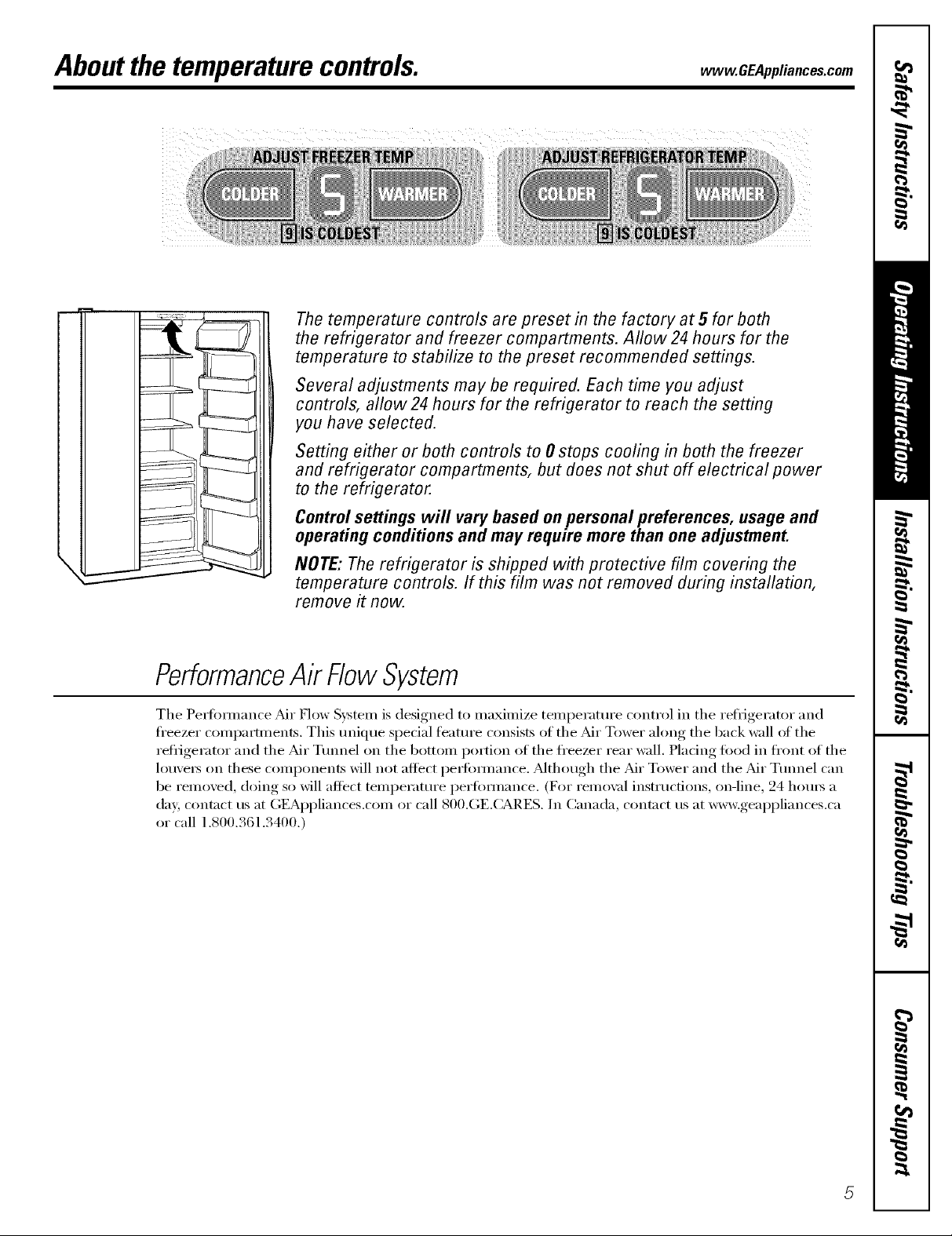
The temperature controls are preset in the factory at 5 for both
the refrigerator and freezer compartments. Allow 24hours for the
temperature to stabilize to the preset recommended settings.
Several adjustments may be required. Each time you adjust
controls, allow24 hours for the refrigerator to reach the setting
you have selected.
Setting either or both controls to 0 stops cooling in both the freezer
and refrigerator compartments, but does not shut off electrical power
to the refrigerator.
Controlsettings will vary based on personal preferences, usage and
operating conditions and may require more than one adjustment.
NOTE: Therefrigerator is shipped with protective film covering the
temperature controls. If this film was not removed during installation,
remove it now.
PerformanceAk FlowSystem
The Pettbt_nance :Mr How Svstetn is designed to nmxinfize temperature control in the reliigerator and
fl'eezer compartments. This tmique spedal feature consists of the Air Tower along the back wall of the
reiiigerator and the _di" Ttmnel on the bottoll_ portion of the fl'eezer rear wall. Pladng fi_od in fl'ont of the
louvers on these compoi_ei_ts will not affect peltbi_lmnce. ?dthough the _dI" Tower and the _dI" Ttmnel can
be removed, doing so will affect temperature perfimnance. (For remo\_fl instructions, on-line, 24 horns a
(la 5 contact us at GEAppliances.com or call 800.(;E.CARES. In Canada, contact us at w_v.geappliances.ca
or call 1.800.361.3400.)
AboutTurboCooEM
How it Works
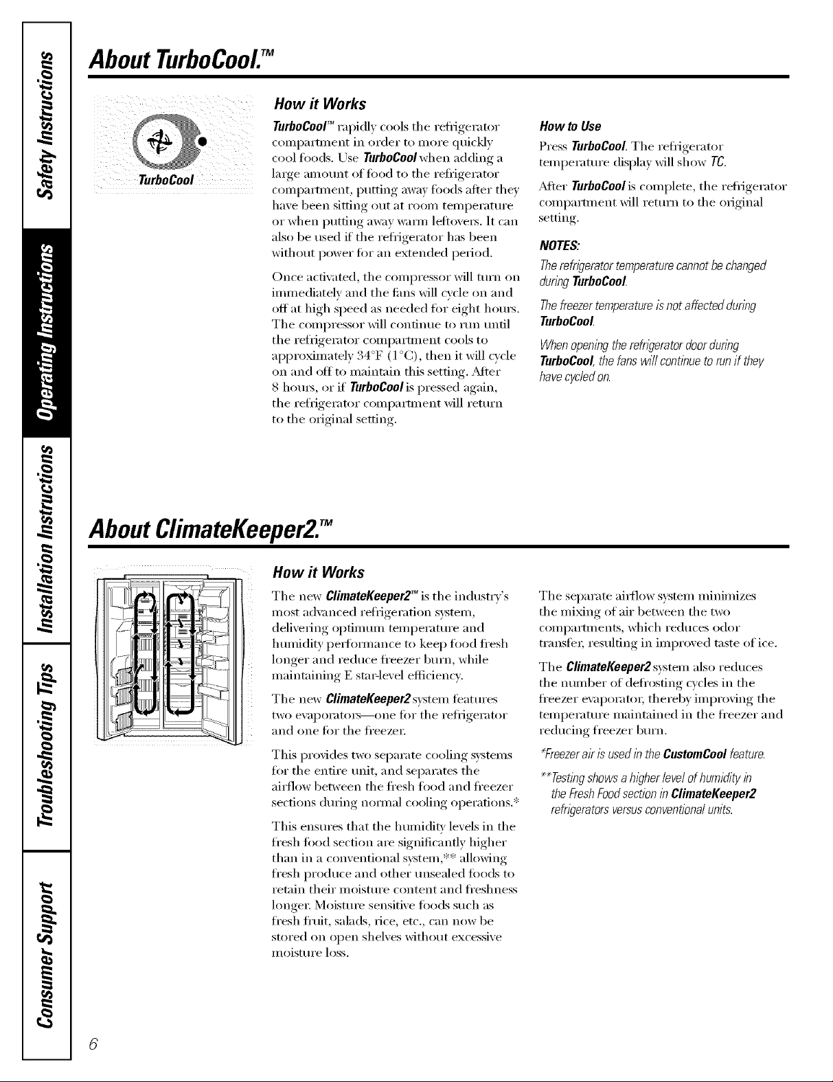
TurboCooY_rapidly cools the refl_igerator
conq)artment in order to more quickly
cool fi>o(ls. Use TurboCool when adding a
i iii iii iii iii iii iii iii iii iii ii
TurboCool
large amount ()f fi)()(l t() the reflJgerator
compartment, putting away fi>o(ls after they
have been sitting (>tit at room teml)erature
or when putting away waxm lefl(>vex_. It can
also be used if the refl_igerat(>r has been
without power fin" an extended period.
Once acfiw_ted, the compressor will tm'n on
immediately and the rims will fide on and
off at high speed as needed fin" eight hems,
The compressor will continue to run tmfil
the refrigerator compartment cools to
approximately 34°F (1 °C), then it will cycle
on and oit to maintain this setting. _Mter
8 hom_, or if TurboCool is pressed again,
the refrigerator compartment will retm'n
to the original setting,
How to Use
Press TurboCooLThe refiigerator
temperature display will show TO.
_Mter TurboCoolis complete, the refi_igerator
COml)artment will return t() the original
setting.
NOTES:
Therefweratortemperaturecannotbechanged
duringTurboCool.
Thefreezertemperatureisnotaffectedduring
TurboCool.
Whenopeningtherefrigeratordoorduring
TurboCool,thefaro will contl)_ueto runif they
havecycledon.
AboutClimateKeeper2Y
14owit Works
The new ClimateKeeper2TM is the industrv's
most a(hmlced refiJgeration system,
delivering optimmn mmperamre and
hmnidity i)e_timnance to kee I) fi>od fl'esh
longer and reduce ti'eezer burn, while
maintaining E sta_qevel efficiency.
The new ClimateKeeper2system featm'es
two evaporator,--one fi)r the refl_igerator
and one fin" the fl'eezet;
This pro\ides two separate cooling systems
fin" the entire refit, and separates the
ai_low between the ti'esh food and ti'eezer
sections (hwing nomml cooling operations.*
This ensm'es that the humidly' levels in the
fl'esh loud section a_e significantly higher
than in a conventional system,** allowing
fresh produce and other tmsealed foods to
retain their moisture content and ti'eshness
longe_: Moisture sensitive toods such as
fresh fi'uit, salads, _ice, etc., can now be
st(wed on (>pen shelves without excessive
lit oisture loss.
The separate ai_low system minimizes
the miMng of air between the two
compartments, which reduces odor
transte_; resulting in improved taste of ice.
The ClimateKeeper2system also reduces
the number of defl'(>sting cycles in the
fl'eezer ex_q)orat(n; thereby improving the
temperature maintained in the ti'eezer and
re(lucing freezer bm'n.
_Freezerak is used in the CustomCool feature.
**Testingshowsa higher/eve/ofhumidityin
theFreshFoodsectioninClimateKeeper2
refweratorsversusconventionaiunits.

Aboutthe water filter.(onsomemodels) www.GEAppliances.com
Onsome models
Place flTetop of the cartridge up
inside the cartridge holder and
slowly turn it to the right.
2 ¸
HOLD3 SECS
Water Filter Cartridge
The water filter cartridge is located in the
back Ul)per right corner of the refl_igerator
COIllI)_l i'tlilent,
When to Replace the Filter
There is a replacement indicator light tin"
the water filter cartridge on the dispense_;
This light will tm'n orange to tell you that
you need to replace the filter soon.
The filter cartridge should be replaced
when the replacement indicator light turns
red or if the flow of water to the dispenser
or icemaker decreases.
Installing the Filter Cartridge
0 If )ou are repladng the cartridge, ti_t
remoxe the old one b)slowl)turning
it to the left. Do not pull down on tile
cartridge. A small amotmt ot water
may drip down.
Fill the replacement cartridge with
water fl'om the trip to allow tin" better
flow fl'om the dispenser immediately
after installation.
Lining up the arrow on the cartridge
@
and the cartridge holder; place the
top of the new cartridge up inside
the holdex; Do not push it up into
the holdex;
0 I)'tm water fl'om the dispenser tot
3 minutes (about one and a half
gallons) to clear the system and
prevent sputtering.
Press and hold the RESETWATERFILTER
pad on the dispenser fk_r 3 seconds.
NOTE" A newEqnsmlled _ter filter
cartridge may cause water to spurt iiom
the dispense_:
Filter Bypass Plug
You must use tile filter bypass plug
when a replacement filter cartridge is not
available. The dispenser and the icemaker
will not operate without the filter or filter
bypass ph N.
Replacement Filters:
To order additional filter cartridges
in the United States, visit our Webs#e,
wvvw.GEAppliances.com,or call GE Parts
andAccessories, 800.626.2002.
(;WF
Suggested Retail $34.95 USD
Customer5 in Canada should consult
tile yellow pages ti_r the nearest Camco
Service Center:
Slowly tm'n it to the right tmfil the filter
cartridge stops. DO NOT OVERTIGHTEN.
_s you tm'n the cartridge, it will
automatically raise itself into position.
Cartridge will rotate about 1/4 turn.
Aboutthe shelves,binsandracks.
Not all features are on all models.
Refrigerator Door Bins and Freezer Door Tilt-Out Bins
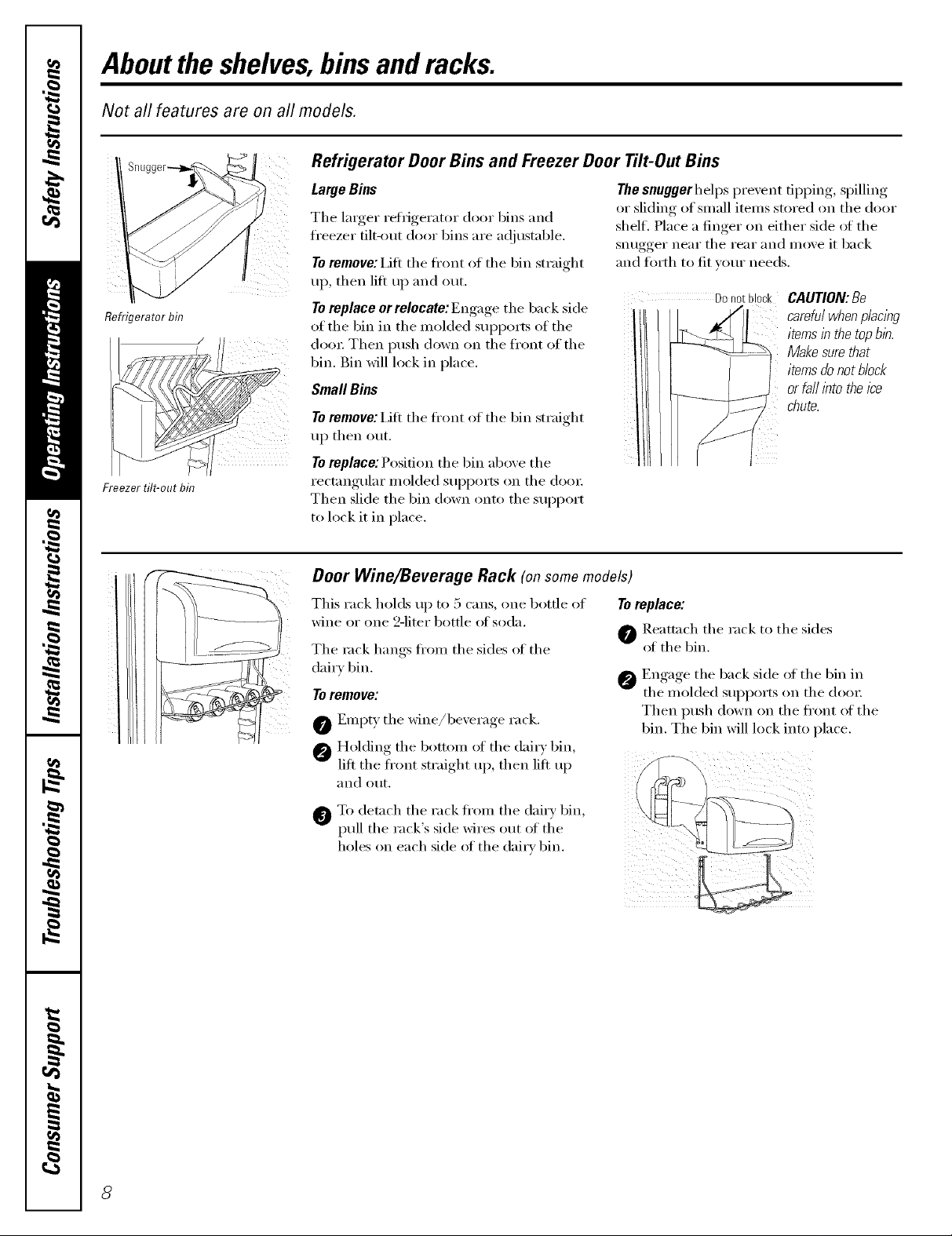
Large Bins
The larger reli_igerator door 1)ins and
fl'eezer filt-_mt door bins are a(!justable,
Toremove: iJfi the fl'ont of the bin straight
up, then lilt up and out.
Refrigerator bin
Freezer tilt-out bin
Toreplace or relocate: Engage the back side
of the bin in the molded SUl)ports of the
door Then push down on the fl'ont of the
bin. Bin will lock in place.
Small Bins
To remove: Lift the fl'ont of the bin straight
up then out.
Toreplace:Position the bin above the
rectangular molded SUl)ports on the (lore;
Then slide the bin down onto the support
to lock it in place.
Thesnuggerhelps prevent tipping, spilling
or sliding of small items stored on the door
shelf, Place a finger on either side _ff the
snugger near the rear and move it back
and tbrth to fit your needs,
Do notblock CAUTION:Be
itemsinthetopb/h.
carefulwhenp/aclbg
Make sure that
items do not block
or fail into the Ice
chute.
Door Wine/Beverage Rack (onsomemodels)
This rack holds up to 5 cans, one bottle of
wine or one 2-liter bottle of soda,
The rock hangs fl'om the sides of the
dairy 1)in,
To remove:
O Empty the wine/bexerage rack.
O Holding the bottom of the dair) bin,
lilt the front smfight up, then lilt up
and Otlt,
To detach the rack fl'om the dairy bin
pull the rack's side wires out of the
holes on each side of the dairy bin.
Toreplace:
Reattach the rack to the sides
of the bin.
Engage the back side of the bin in
the molded supp(>rts (m the (loot:
Then push down on the fl'ont ()I the
bin. The bin will lock into place.

Press tab and pull shelf
forward toremove
www.GEAppliances.com
Slide-Out Spillproof Shelf
The slide-out spillproof shelf allo_s )_m
to reach items stored behind othe_s. The
special edges are designed to hel I) prevent
spills from dripping to lower shelves.
Toremove:
Slide the shelf out tmtil it reaches the stop,
then press down on the tab and slide the
shelf straight out.
Toreplaceorrelocate:
I,ine the shelf uI) with the suI_ports and
slide it into place. The shelf can be
repositioned when the door is at 90 ° or
more. To reposition the shelf; slide the shelf
past the stops and angle downward. Slide
shelf down to the desired position, line up
with the supports and slide into place.
Make sure you pushthe shelves all the way back
in before you close the door
ii i )i! i ;iI
OuickSpace TM Shelf
This shelf splits in half and slides under
itself fin" storage oI tall items on the shelf
below.
This shelf can be removed and replaced
or relocated just like Slide-Out Spillproof
Shelves,
Freezer Baskets
Toremove, slide out to the stopposition,
lift the fi'ont past the stop position, and
slide out.
On some models, the flfll extension basket
can be removed by pushing the basket all
Slide-OutFreezerShelves
Toremove, slide out to the stopposition,
lift the ti'ont past the stop position, and
slide out.
On some models, this shelf can not be used
in the lowest position.
the way to the back of the fl'eeze_: i,ifl up
tmfil the back pins are disengaged, i,ift the
entire basket up and pull out.
Make sure you push the baskets all the way back
in before you close the door
Makesureyoupushthe shelvesall the wayback
in beforeyoudose the door
Fixed Freezer Shelves
To remove, lift the shelf up at the left side
and then bring the shelf out.
NOTE FOR DISPENSER MODELS: In order
to take flfll advantage oI the tilt-out ice bin,
only store items on the shelf below the ice
bin that are no taller than the lowest point
on the bin.
Aboutthe refrigeratordoors.
Refrigerator Doors
iii
ii
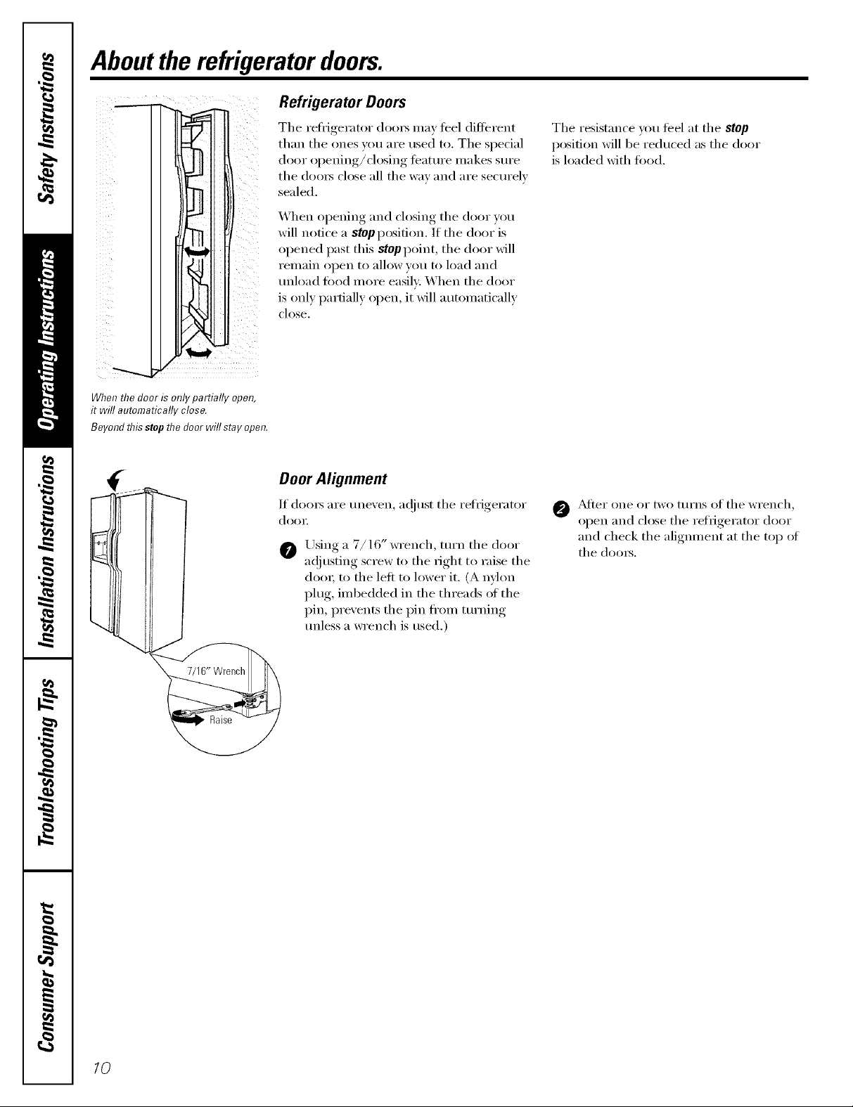
When the door is only partially open,
it will automatically close.
Beyond flTisstop flTedoor will stay open.
The reti_igerator (loo_ may teel different
than the ones you are used to. The special
door opening/closing feature nlakes sure
the/loo_ close all the way and are securelv
sealed.
When opening and closing the door you
will notice a stop position. If the door is
opened past this stop point, the door will
I'elllain open to allow VOtl to load and
unload fi)od more easily. When the door
is only partially open, it will automatically
close.
Door Alignment
If (loo_ are unexen, a(!iust the refrigerator
door
Using a 7/16" wrench, turn the door
a(!iusting screw to the right to raise the
door; to the left to lower it. (A nylon
plug, imbedded in the threads ot the
pin, prevents the pin fl'om turning
unless a wrench is used.)
The resistance you ti_el at the stop
position will be reduced as the door
is loaded with fi)od.
O _Mter one or two turns of the wrench,
oi)en.... and close the refrigerator, door
and check the alignment at the top of
the (loo_s.
10
Aboutthe crispersand pans. vvww.GEAppliances.com
Not all features are on all models.
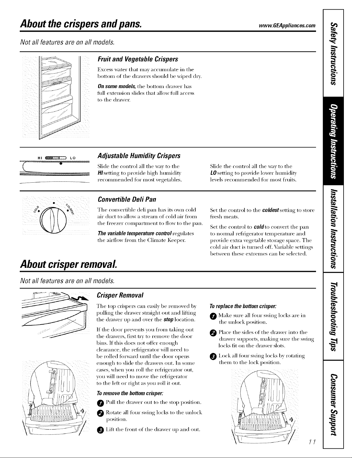
Excess water that may accunmlate in the
Fruit and Vegetable Crispers
bottom of the (h'awe_ should be wiped (h_'.
On some models, the bottom drawer has
filll extension slides that allow fifll access
to the (h'awe_;
HI _ LO
Q_
Adjustable Humidity Crispers
Slide the control all the way to the
H/setting to proxide high humidit_
recommended for most xegetables.
Convertible Deli Pan
The comertible deli pan has its own cold
air duct to allow a stream of cold air from
the fl'eezer compartment to flow to the pan.
The variable temperature control regulates
the airflow fl'om the Climate Keeper
Aboutcrisperremoval
Not all features are on all models.
Crisper Removal
The top ('rispe_ can easily be removed by
pulling the drawer straight out and lifting
the drawer up and over the stop location.
If the door prevents you from taking out
the di'awei's_ tii'st try to i'elllOVe the do()r
bins. If this does not Offer enotlgh
clearance, the refl_igerator will need to
be rolled fi)rward tmtil the door opens
enough to slide the (h'awe_ out. In some
cases, when you roll the reti_igerator out,
you will need to move the refl_igerator
to the left or right as you roll it out.
To remove the bottom crisper:
@ Pull the drawer out to the stop position.
Slide the control all the way to the
tO setting to proxide h)wer h umidit}
lexels recommended for most fruits.
Set the control to the coldestsetfing to store
fl'esh meats.
Set the control to coldto convert the pan
to normal reflJgerator temperature and
provide extra vegetable storage space. The
cold air duct is turned ottl Variable settings
between these extremes can be selected.
Toreplace the bottom crisper:
Make sm'e all fimr _swim,_locks are in
the mflock position.
Place the sides of the drawer into the
drawer supports, making sm'e the ,swim,
locks fit on the drawer slots.
I,ock all fimr swing locLs by rotating
them to the lock position.
@ Rotnte all fimr swing locks to the mflock
position.
0 I,itt the fl'ont oI the drawer up and ()tit.
11
Aboutthe automaticicemaker.
A newly installed refrigerator may take 12to 24 hours to begin making ice.
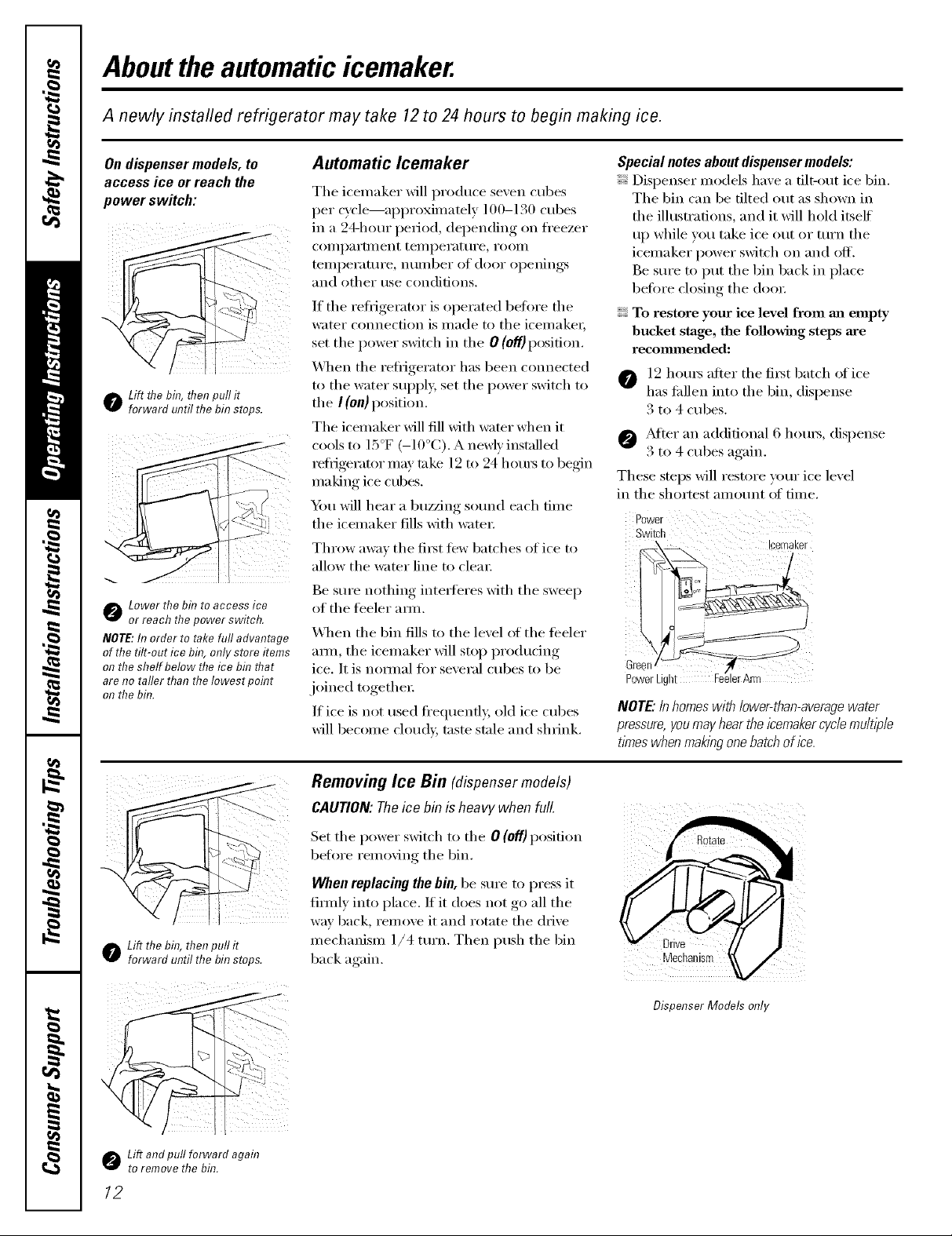
On dispenser models, to Automatic Icemaker
access ice or reach the
power switch:
o Lift flTebin, flTenpull it
forward until the bin stops.
Lower the bit?to access ice
or reach thepower switch.
NOTE:In order to take full advantage
of the tilt-out ice bh?,only store items
on the shelf below the ice bit?tt?at
are no taller than the Iowest poh?t
on the bh?.
The icemaker will produce seven cubes
per Q'cle--approximately ] 00-130 cubes
in a 24-hour period, depending on fl'eezer
(oI/ll)}II'tlllent [ei/lpei';ittli'e_ i'OOill
temperature, number of door openings
and other use conditions.
If the refrigerator is operated before the
water connection is made to the icemaket;
set the power switch in the O (off) position.
_._]_en the refl_igerator has been connected
to the water SUl)ply, set the power switch to
the I (on) position.
The icemaker will fill with water when it
cools to 15°F (-10°C). A newly inst;dled
retiJgerator may take 12 to 24 h otu_ to begin
making ice cubes.
_Am will hear a buzzing sotmd each time
the icemaker fills with water:
Throw away the fi_t few batches of ice to
allow the water line to clea_:
Be sure nothing inte_feres with the sweep
of the feeler amL
\._]_en the bin fills to the level ot the teeler
am_, the icemaker will stop produdng
ice. It is nomml tor several cubes to be
joined mgethei:
If ice is not used fi'equenfl 5 old ice cubes
will become cloudy, taste stale and shrink.
Special notes about dispenser models:
Dispenser models have a tilt-out ice bin.
The bin can be tilted out as shown in
the ilhlstrations, and it will hold itself
up while you take ice out or mrn the
icemaker power switch on and off.
Be sure to put the bin back in place
before closing the doo_:
To restore your ice level from an empty
bucket stage, the following steps are
recommended:
O 12 hom_ after the fiI_t batch of ice
has fidlen into the bin, dispense
3 to 4 cubes.
@ _M*eI" an additional 6 hom_, dispense
3 to 4 cubes again.
These steps will restore your ice level
in fl_e shortest amount of time.
Power
Switch
NOTE"/nhomes with lower-than-average water
pressure,youmay hear the icemakercyclemultiple
times when mak/bgone batch of ice.
o Lift thebit?,then pull it
forward until the bit?stops.
Lift and pull forward again
to remove the bit?.
12
Removing Ice Bin (dispensermodels)
CAOTlON:Theice bin is heavywhenfulL
Set the power switch to the 0 (off) position
beli)re removing the bin.
When replacing the bin, be sure to press it
firefly into place. If it does not go all the
way back, remove it and rotate the drive
mechanism 1/4 turn. Then push the bin
back again.
Dispenser Models only
Aboutthe ice and water dispenser.(onsomemodels) wvvw.GEAppliances.com
Onsome models
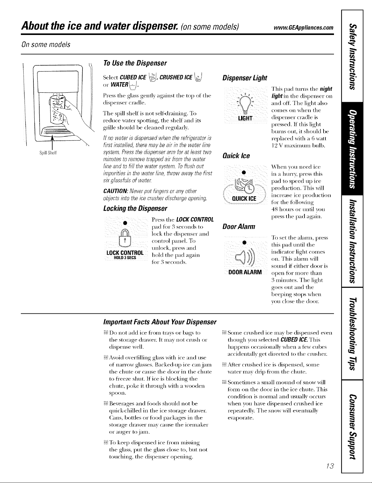
To Use the Dispenser
SpillShelf
Select CUBED ICE I_I, CRUSHEDICE
or WATERI_(.J.
Press tile glass gently against tile top ot tile
dispenser cradle,
The spill shelf is not seltkh'aining, To
reduce water spotting, tile shelf and its
grille shouM be cleaned regularly.
If no water is dispensed when the refngeretor is
first instafled, there may be air in the water line
system. Press the dispenser arm for at least two
minutes to remove trapped ak from the water
line and to fill the water system. Toflush out
impurities in the water fine, throw away the first
slk glassfuls of water
CAUTION: Never put fingers or any other
objects into the ice crusher discharge opening.
Lockingthe Dispenser
Press the LOCKCONTROL
pad fi)r 3 seconds to
h>ck tile dispenser and
control panel, To
unlock, press and
LOCKCONTROL hold tile pad again
HOLD3 SECS J()I" ._ seconds,
Dispenser Light
This pad turns tile night
light in tile dispenser on
and off. Tile light also
coI//es on when tile
LIGHT
dispenser cradle is
pressed. If this light
burns out, it should be
replaced with a 6 watt
]9 V maxim mn bulb.
Qu_k_e
X'\hen you need ice
• in a h urr,_; press this
pad to speed up ice
............. production. This will
QUICKICE
.............................................................................for tile following
increase ice production
48 hom_ or tmtil you
press the pad again.
DoorAlarm
To set tile alamo, press
this pad tmfil tile
indicator light comes
on. This almm will
solmd if either door is
DOORALARM
open t()I" illoi'e than
3 minums. Tile light
goes out and the
beeping stops when
vou close tile dool:
Important Facts About Your Dispenser
Do not add ice Ii'om trays or bags to
tile storage drawer. It may not crush or
dispense well.
Avoid overfilling glass with ice and use
of narrow glasses. Backed-up ice can jam
tile chute or cause tile door in tile chute
to freeze shut. If ice is blocking the
chute, poke it through with a wooden
spo()n.
Beverages and toods shoukl not be
quick-chilled in the ice storage drawer.
Cans, bottles or Iood packages in tile
storage drawer may cause tile icemaker
or a/iger to jalll,
To kee I) dispensed ice fl'om missing
tile glass, put tile glass close to, but not
touching, tile dispenser opening.
Some crushed ice may be dispensed even
though you selected CUBEDICE.This
happens occasionally when a few cubes
accidentally get directed to the crushe_:
_Mter crushed ice is dispensed, some
water may drip fl'om tile chute.
Solnefilnes a small Inound of snow will
tbm/on tile door in tile ice chute. This
condition is nolinal and usualk occui5
when you have dispensed crushed ice
repeatedly. Tile snow will eventually
evapoI'ate.
13
Careand cleaningof the refrigerator.
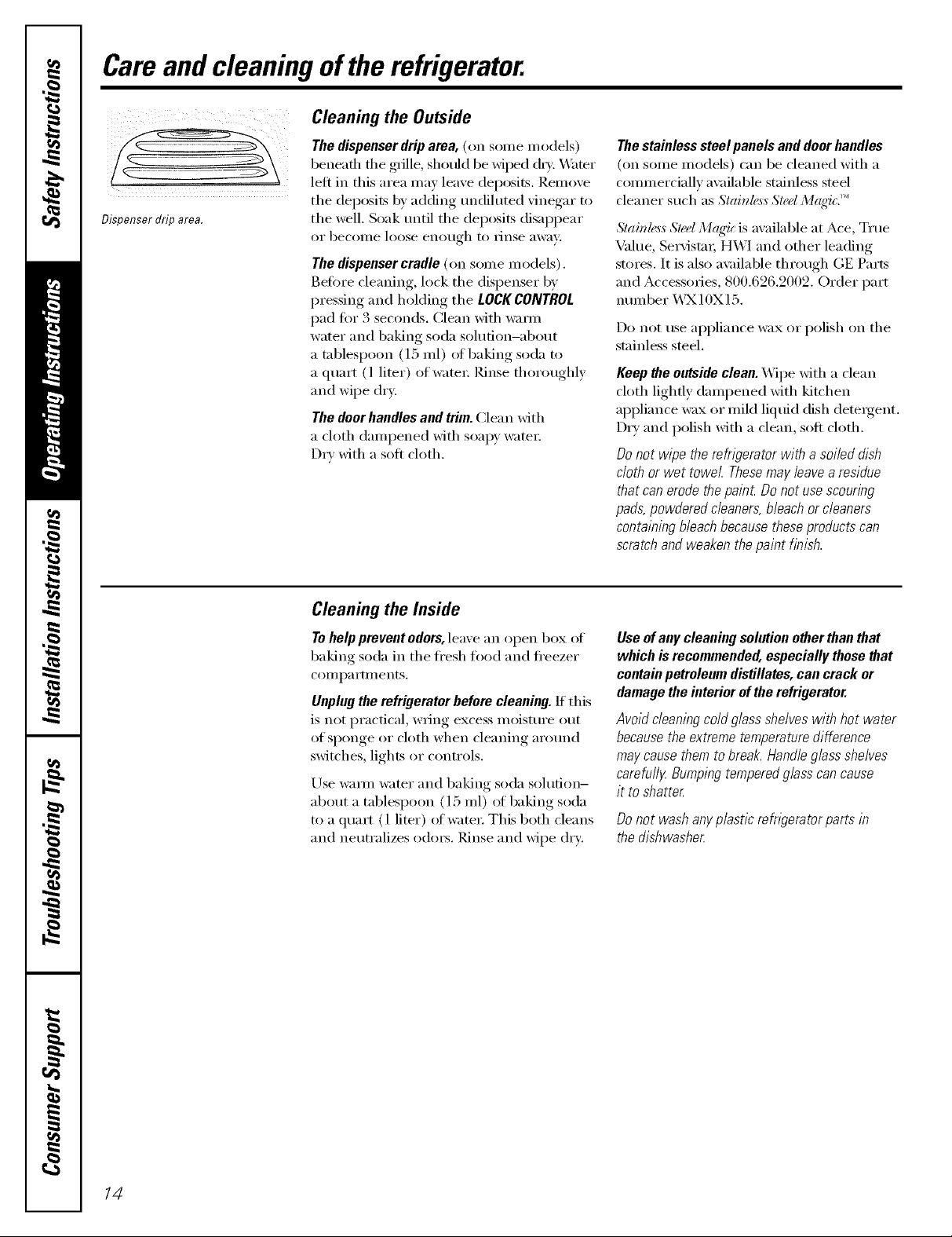
Cleaning the Outside
The dispenser drip area, (on some models)
beneath the grille, should be wiped d_T. _,V_ter
left in this area may leave deposits. Remove
the deposits by adding mMiluted vinegar to
Dispenser drip area.
the well. Soak tmtil the deposits disappear
or becoille loose enotlgh to Finse awaY:
The dispenser cradle (on some models).
getore cleaning, lock the dispenser by
pressing and hoMing the LOCK CONTROL
pad fin" 3 seconds. Clean with warn/
water and baking soda solution-about
a tablespoon (l 5 ml) ot baking soda to
a (lua_t (l liter) of wam_: Rinse thoroughly
and wipe dr*:
The doorhandles and trim. Clean with
a cloth dampened with soapy water:
Dry with a soft cloth.
The stainless steel panels and door handles
(on some models) can be cleaned with a
commercially available stainless steel
cleaner such as Slahde, s,sSh'd M(l_'ic.''_
Slainl_,,_,_Sled Mc_q4cis awfilable at Ace, Tree
Value, Se_Mstm; HX4'/and other leading
stores. It is also a\:filable through GE Parts
and Accessories, 800.626.2002. Order part
nmnber X&3X10X15.
Do not use appliance wax or polish on the
stainless steel.
Keep tile outside clean. Wipe Mth a clean
cloth lightly dampened Mth kitchen
appliance wax or mild liquid dish detergent.
Dry and polish with a clean, soft cloth.
Do not wipe the refrigerator with a soiled dish
cloth or wet towel Thesemay leave a residue
that can erode the paint Do not use scouring
pads,powdered cleaners, bleach or cleaners
containing bleach because these products can
scratch and weaken the paint finish.
Cleaning the Inside
Tohelp prevent odors, leave an open box of
baking soda in the fl'esh ti)o(l and fl'eezer
COlI/pa i'tlilents.
Unplug the refrigerator before cleaning. If this
is not practical, wring excess moisture out
of sponge or cloth when cleaning arotmd
switches, lights or controls.
Use wama water and baking soda solution-
about a tablespoon (15 ml) of baking soda
to a quart (l liter) of water: This both cleans
and neutralizes o(lm_. Rinse and wipe dry:
Useof any cleaning solution other than that
which is recommended, especially those that
contain petroleum distillates, can crack or
damage the interior of the refrigerator.
Avoid cleaning cold glass shelves with hot water
because the extreme temperature difference
may cause them to break. Handle glass shelves
carefufl_zBumping tempered glass can cause
it to shatter
Donot washanyplastic refrigeratorpartsin
thedishwasher
/4
Behind the Refrigerator
Be caretill when moving the reti_igerator
away from the wall. _M1 t,ipes of floor
coverings can be dmnaged, particulady
cushioned coverings and those with
embossed stm'hces.
Pull the refl_igerator straight out and return
it to position by pushing it straight in.
Moving the reflJgerator in a side direction
may result in damage to the floor covering
or reti_igeratm:
Preparing for Vacation
vvvvvv.GEAppliances.com
When pushlbg the refrigerator back, make sure
you don't roll over the power cord or icemaker
supply line {onsome models).
For long \31(-ations or absences, i'eil/ove
food and unphlg the reflJgeratoi: Clean
the interior with a baking soda solution
of one tablespoon (l 5 ml) of baking soda
to one quart (l liter) of water; i,eave the
dooI_ open.
Set the icemaker power switch to the
0 (off) position and shut off the water supply
to the refiigeratm:
Preparing to Move
Secure all loose items such as shelves and
(h'awe_ by tnping them securely in place
to prevent damage.
_4]_en using a hand truck to move the
refl_igerato_; do not rest the fl'ont or back
of the refl-igerator against the hand truck.
This could damage the refrigerator. Handle
only fl'om the sides of the refi_igeratm:
Be sure the refn)erator stays in an upn)ht
positionduringmoving.
If the temperature can drop below fl'eezing,
have a qualified servicer drain the water
supply s):stein (oil some models) to prevent
serious proper F dalnage due to flooding.
/5
Replacingthe lightbulbs.
Setting the controls to OFFdoes not remove power to the light circuit.
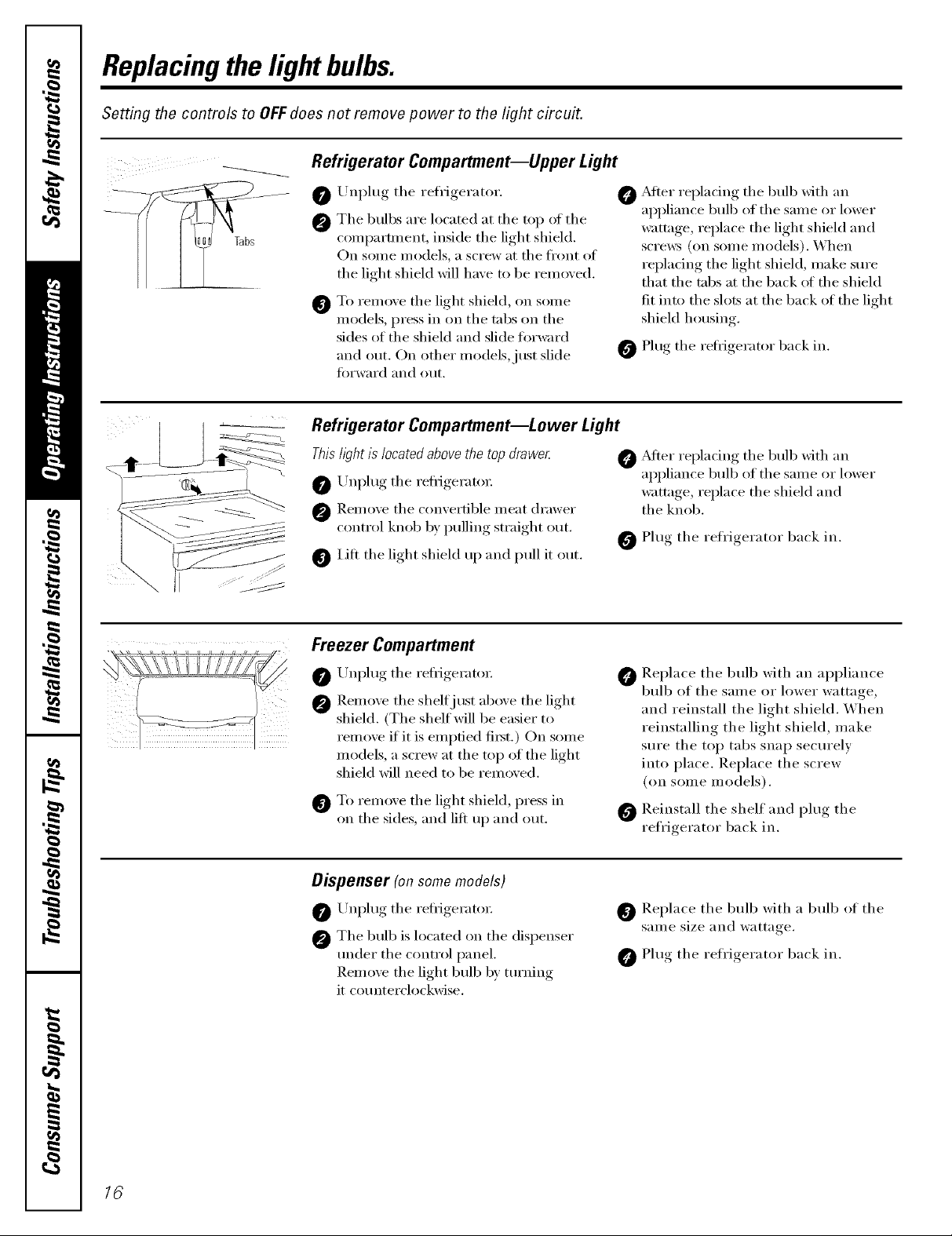
___ Refrigerator Compartment--Upper Light
Tabs
Unplug tile refl'igerator.
0
Tile bulbs are located at tile top of tile
0
compartment, inside the light shield.
On some models, a screw at tile fl'ont of
the light shield will have to be removed.
To rein(we tile light shield, on solne
@
models, press in on the tabs on the
sides of the shield and slide fin'ward
and out. On other models,just slide
fin'ward and (>/It.
Refrigerator Compartment--Lower Light
Thishght is located above the top drawe_
O Unl)lug tile refrigerator:
@ Remo'_e tile comertible meat drawer
control knob b) pulling straight out.
lilt the light shield up and pull it out.
Freezer Compartment
O Unl)lug tile refrigerator:
@ Remoxe the shelfj ust aboxe tile light
shield. (The shelf will be easier to
remoxe if it is emptied fi_t.) On some
models, a screw at tile top of tile light
shield will need to be remoxed.
To remoxe tile light shield, press in
on tile sides, and lift up and out.
O ,Mter repladng tile bulb with an
appliance bulb of tile same or lower
wattage, replace the light shield and
scrmvs (on some models). When
replacing the light shield, make sure
that the tabs at the back ot the shield
fit into tile slots at tile back of tile light
shield housing.
O Plug the refligerator back in.
O _Mter replacing tile bulb xfith an
appliance bulb of tile same ()r lower
wattage, replace the shield and
the knob.
0 Plug tile refrigerator back in.
Replace tile bull) with an appliance
0
bulb of tile same or lower wattage,
and reinstall the light shield. When
reinstalling the light shield, make
sure tile top tabs snap securely
into place. Replace the screw
(on some models).
Reinstall tile shelf and plug tile
refrigerator back in.
16
Dispenser (onsomemodels)
O Unplug tile refligerato_:
@ Tile bulb is located on tile dispenser
under tile control panel.
Remoxe tile light bulb b) turning
it counterclockwise.
O Replace tile bulb with a bulb of tile
same size and wattage.
Plug tile refrigerator back in.
Trimkits anddecoratorpanels.
For CustomStyle TM models
Read these instructions completely and carefully.
BeforeYouBegin
Some models are equipped with trim kits that aflow you to instafl door panels. You can order
pre-cut black, white, bisque or stainless steel decorator panels from GE Parts and Accessories,
800.626.2002,or you can add wood panels to match your kitchen cabinets.
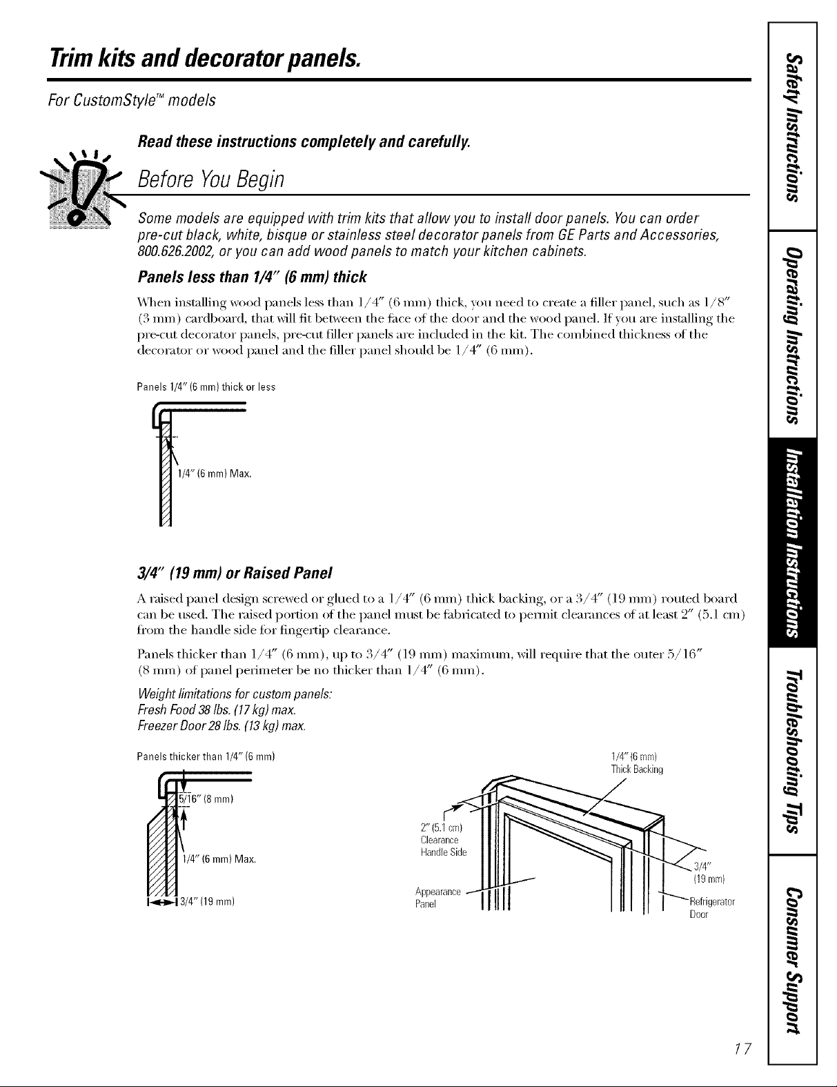
Panels less than 1/4" (6 mm) thick
\,_]_en installing wood panels less than ]/4" (6 ram) thick, you need to create a filler panel, such as 1/8"
(3 mm) cardboard, that will fit 1)etween the ti_ce of the door and the wood panel. If you are installing the
pre-cut decorator panels, pre-cut filler panels are included in the kit. The combined thickness ot the
decorator or wood panel and the filler panel shotfld be 1/4" (6 ram).
Panels 1/4" (6 mm)thick or less
1/4"(6 mm) Max.
3/4" (19 mm) or Raised Panel
A raised panel design screwed or glued to a l/4" (6 ram) thick backing, or a./4 (19 ram) routed board
can be tlsed. The raised portion of the panel nltlSt be fid)ricated to pemfit clearances of at least 2" (5. l cm)
from the handle side fin" fingerti, I) clearance
•/4 (19 ram) maMmum, will require that the outer :!/16Panels thicker than l/4" (6 ram), uI) to 3 .....
(8 ram) of panel perimeter be no thicker than 1/4" (6 ram).
Weightlimitationsfor custompanels:
FreshFood38Ibs.(17kg) max.
FreezerDoor28Ibs.(13kg)max.
Panels thicker than 1/4" (6 mm)
5/16" (8 ram)
mm) Max.
1/4"(6ram)
ThickBacking
I_13/4" (19mm)
°hoeqli[11 I _-_'Refrigerater
Door
17
Trimkits anddecoratorpanels.
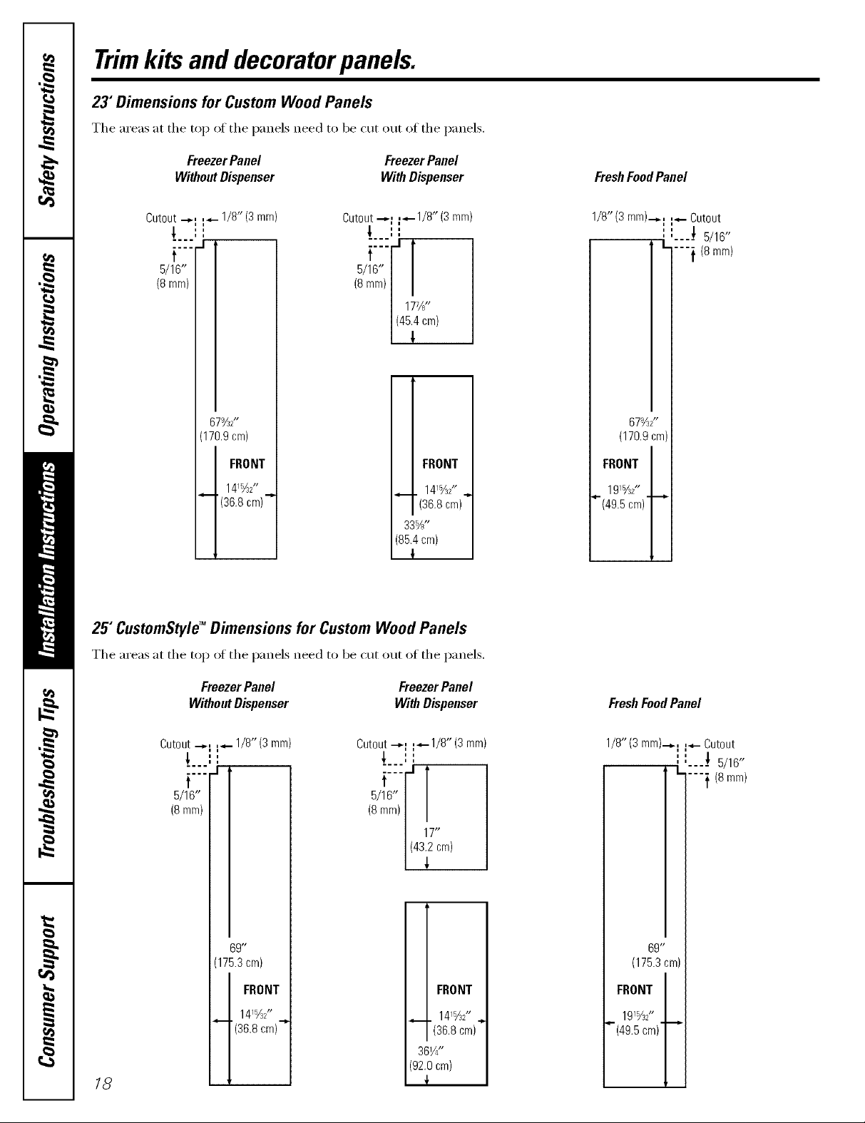
23"Dimensions for Custom Wood Panels
The areas at the top of the panels need to be cut out of the panels.
Freezer Panel Freezer Panel
Without Dispenser With Dispenser
FreshFoodPanel
Cutout "-'I I_'- 1/8" (3 rnm)
t, ''
i i
.... .I
Cutout "-'I 1_-1/8" (3 rnm)
,,
i i
t
6/16"
(Smm)
/8mmt!/
/ 177/¢'
67%Z'
(170.9 cm)
FRONT
1415/J2"
'(36.8 cm)"
25" CustomStyle TMDimensions for Custom Wood Panels
i FRONT
141%Z' ..,
(36.8 cm)
33%"
(85.4 cm)
!
1/8"(3 rnrn)-_,,l I-"- Cutout
',',...! 5/16"
I_
""i (8 mr'n)
67YS'
(170.9 cm)
FRONT
1915/32"
_(49.5 cm)' "-_
The areas at the top oI the panels need to be cut out oI the panels.
Freezer Panel Freezer Panel
Without Dispenser With Dispenser
Cutout "-"I 14- 1/8" (3 ram)
''
i i
Cutout "-"I V"-118" (3 ram)
,l ''
i i
t
5/16"
(8 mm)
69"
(1752 cm)
FRONT
i FRONT
14%2'
_--"(36.8 cm) _
18
14/J2 ,.,
(36.8 ore)
361/4"
(92.0 cm)
{
15 t#
FreshFoodPanel
1/8'#(3 rnrn)'-_l I"- Cutout
" "----_ 5/16"
"---1 (8ram)
69"
(1753cm)
FRONT
191%2"
_-(49.5cm)""-"
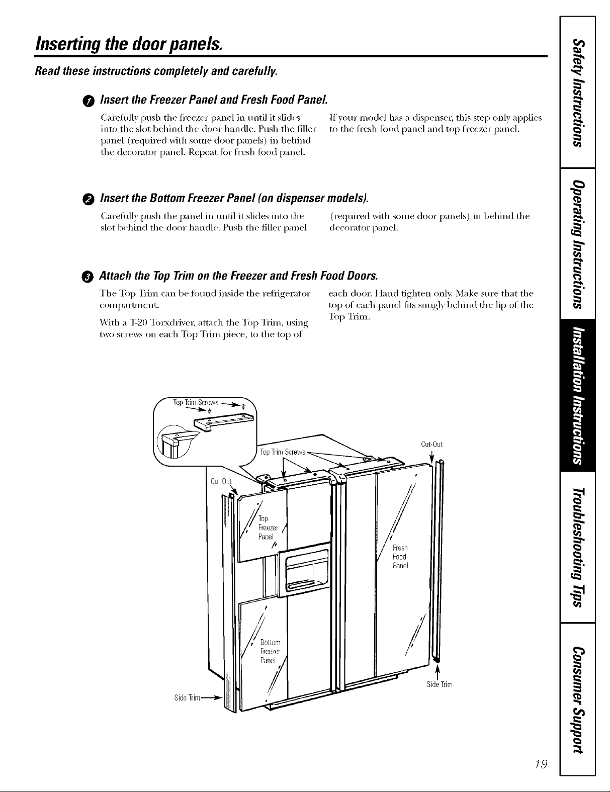
Insertingthedoorpanels.
Read these instructions completely and carefully.
0 Insert the Freezer Panel and Fresh Food Panel
Carefully push the ti'eezer panel in until it slides
into the slot behind the door handle. Push the filler
panel (required with some dooi" panels) in behind
the decorator panel. Repeat fi)r fl'esh fi)od panel.
0 Insert the Bottom Freezer Panel (on dispenser models).
Carefull) push the panel in until it slides into the (required with some door panels) in behind the
slot behind the door handle. Push the filler panel decorator panel.
0 Attach the TopTrim on the Freezer and Fresh Food Doors.
The Top T_im can be t0und inside the reliigerator each (loo_: Hand tighten only. Make sure that the
compartment, top ot each panel fits snugly behind the lip ot the
_ith a T-20 Torxd_i\'e_; attach the Top TFim, using Top TFim.
two screws on each Top TFim piece, to the top of
If)our model has a dispense_, this step only applies
to the fl'esh fi_od panel and top freezer panel.
Cut-Out
SideTrim
t
19
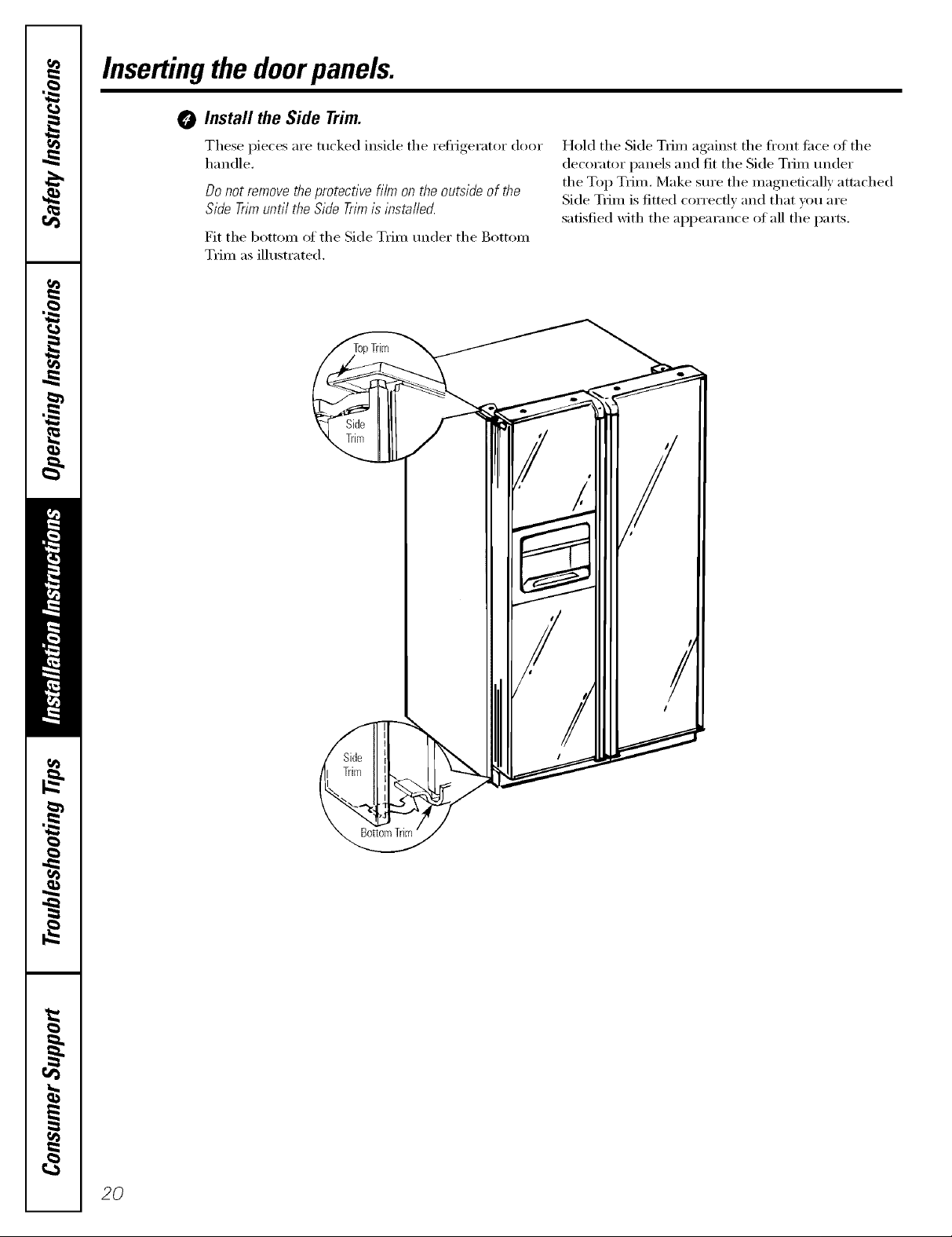
Insertingthedoorpanels.
O Install the Side Trim.
These pieces are tucked inside the refl_gerator door
handle.
Donot removetheprotectivefilm on theoutsideof the
SideTrimuntil theSideTrimisinstafled.
Fit the bottom of the Side Trim under the Bottom
Trim as illustrated.
Hold the Side Tdm against the fl'ont ti_ce of the
decorator panels and fit the Side Tdm under
the Top Tdm. Make sure the magnetically am_ched
Side Tdm is fitted correctly and that xxm are
satisfied with the appearance of all the parts.
2O
Installation
Refrigerator
Instructions
I Questions? Call 800.GE.CARES (800.432.2737) or Visit our Website at: GEAppliances.com
BEFORE YOU BEGIN
Read these instructions completely
and carefully.
• IMPORTANT - Savethese
instructions for local inspector's use.
• IMPORTANT - Observeall
governing codes and ordinances.
• Note to Installer - Be sure to leave these
instructions with the Consumer.
• Note to Consumer - Keep these
instructions for future reference.
• Skill level - Installation of this appliance
requires basic mechanical skills.
• Completion time - Refrigerator Installation
• Proper installation is the responsibility of
the installer.
In Canada, call 1.800.361.3400 or Visit our Website at: geappliances.ca
30 minutes
Water Line Installation
30 minutes
Models 23, 25, 26, 27 & 29
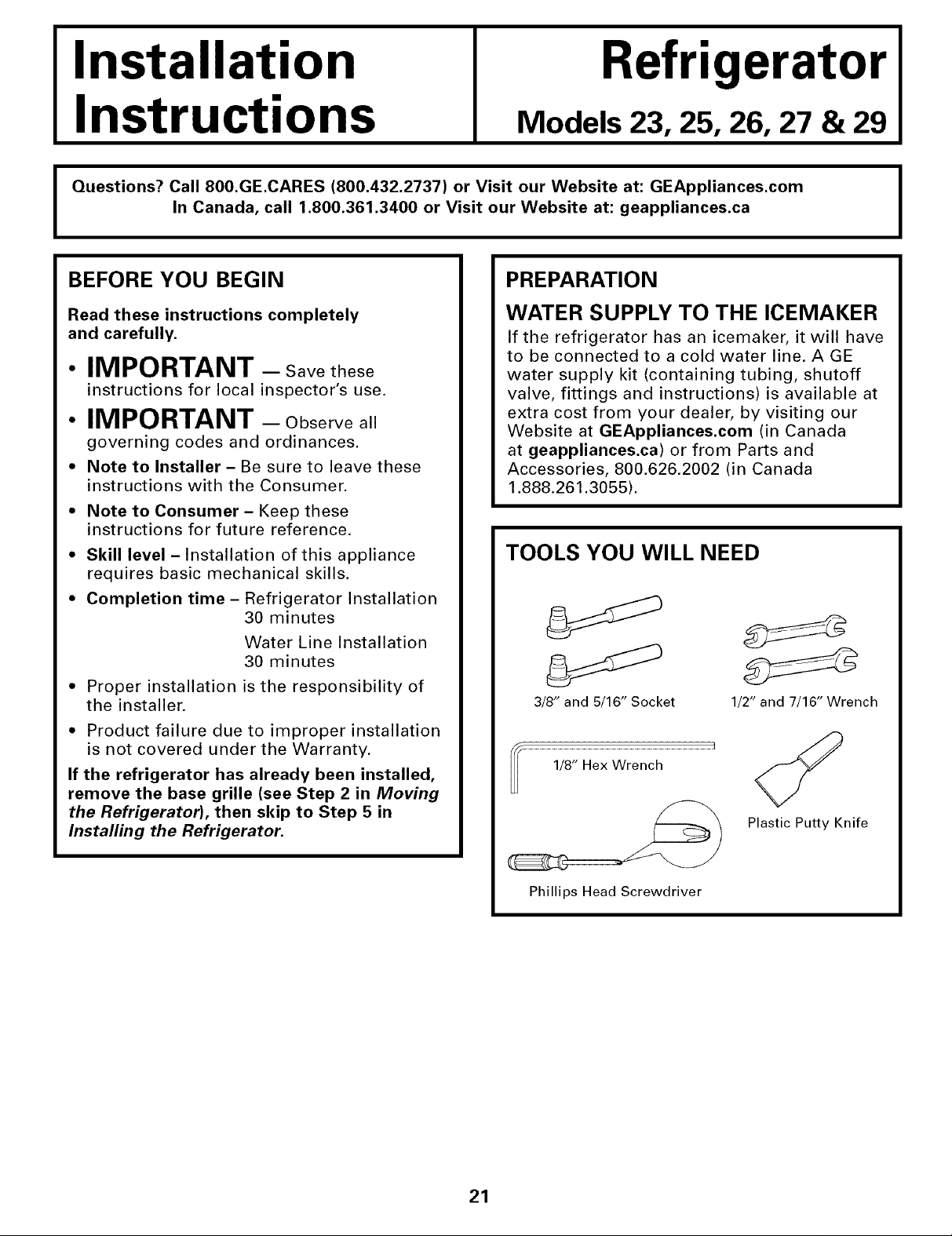
PREPARATION
WATER SUPPLY TO THE ICEMAKER
If the refrigerator has an icemaker, it will have
to be connected to a cold water line. AGE
water supply kit (containing tubing, shutoff
valve, fittings and instructions) is available at
extra cost from your dealer, by visiting our
Website at GEAppliances.com (in Canada
at geappliances.ca) or from Parts and
Accessories, 800.626.2002 (in Canada
1.888.261.3055).
TOOLS YOU WILL NEED
3/8" and 5/16" Socket 1/2" and 7/16" Wrench
I
• Product failure due to improper installation
is not covered under the Warranty.
If the refrigerator has already been installed,
remove the base grille (see Step 2 in Moving
the Refrigerator), then skip to Step 5 in
Installing the Refrigerator.
Plastic Putty Knife
Phillips Head Screwdriver
21
Installation Instructions
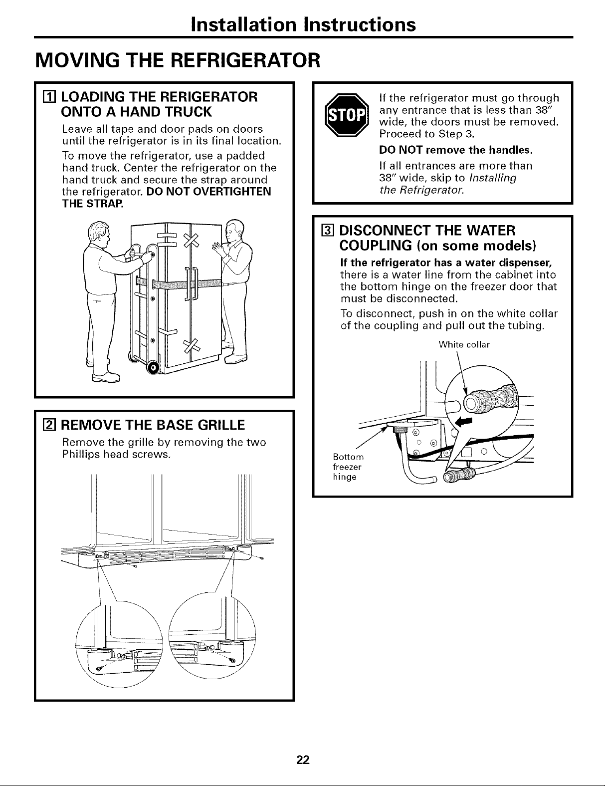
MOVING THE REFRIGERATOR
[] LOADING THE RERIGERATOR
ONTO A HAND TRUCK
Leave all tape and door pads on doors
until the refrigerator is in its final location.
To move the refrigerator, use a padded
hand truck. Center the refrigerator on the
hand truck and secure the strap around
the refrigerator. DO NOT OVERTIGHTEN
THE STRAP.
If the refrigerator must go through
any entrance that is less than 38"
wide, the doors must be removed.
Proceed to Step 3.
DO NOT remove the handles.
If all entrances are more than
38" wide, skip to Installing
the Refrigerator.
[] DISCONNECT THE WATER
COUPLING (on some models)
If the refrigerator has a water dispenser,
there is a water line from the cabinet into
the bottom hinge on the freezer door that
must be disconnected.
To disconnect, push in on the white collar
of the coupling and pull out the tubing.
White collar
[] REMOVE THE BASE GRILLE
Remove the grille by removing the two
Phillips head screws.
Bottom
freezer
hinge
22
Installation Instructions
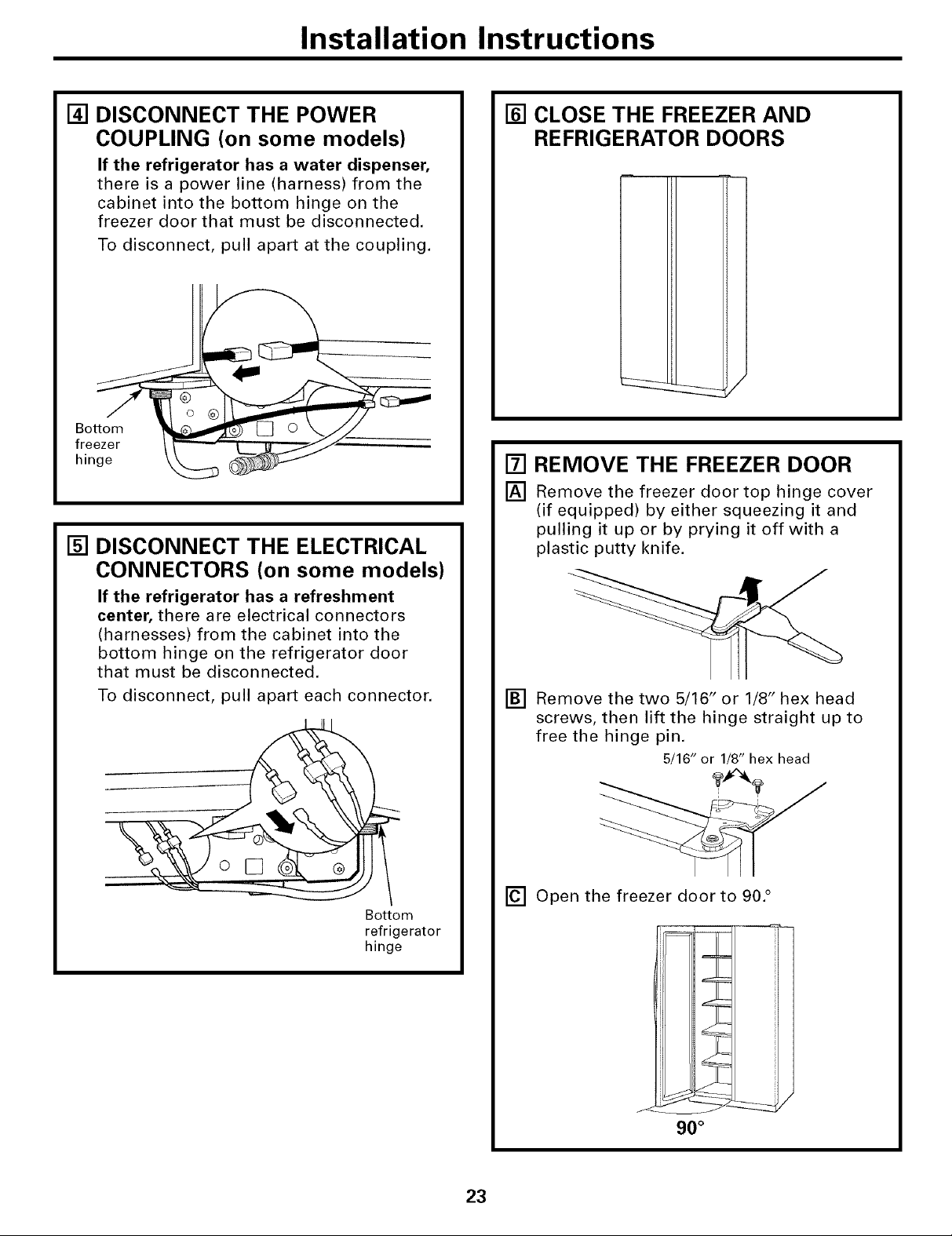
[] DISCONNECT THE POWER
COUPLING (on some models)
If the refrigerator has a water dispenser,
there is a power line (harness) from the
cabinet into the bottom hinge on the
freezer door that must be disconnected.
To disconnect pull apart at the coupling.
[] DISCONNECT THE ELECTRICAL
CONNECTORS (on some models)
If the refrigerator has a refreshment
center, there are electrical connectors
(harnesses) from the cabinet into the
bottom hinge on the refrigerator door
that must be disconnected.
To disconnect, pull apart each connector.
[] CLOSE THE FREEZER AND
REFRIGERATOR DOORS
[] REMOVE THE FREEZER DOOR
[] Remove the freezer door top hinge cover
(if equipped) by either squeezing it and
pulling it up or by prying it off with a
plastic putty knife.
[] Remove the two 5/16" or 1/8" hex head
screws, then lift the hinge straight up to
free the hinge pin.
5/16" or 1/8" hex head
Bottom
refrigerator
hinge
[] Open the freezer door to 90. °
90 °
23

Installation Instructions
MOVING THE REFRIGERATOR (CONT.)
[]
REMOVE THE FREEZER DOOR
(cont.)
[]
As one person slowly lifts the freezer door
up and off the bottom hinge, the second
person should carefully guide the water
line and power line (harness) through the
bottom hinge.
_
90°
[] REMOVE THE REFRIGERATOR
DOOR (cont.)
[] Remove the two 5/16" or 1/8" hex head
screws, then lift the hinge straight up to
free the hinge pin.
[] Open the refrigerator door to 90. °
5/16" or 1/8" hex head
[] Set the door on a non-scratching surface
with the inside up.
[] REMOVE THE REFRIGERATOR
DOOR
[] Remove the refrigerator door top hinge
cover (if equipped) by either squeezing it
and pulling it up or by prying it off with
a plastic putty knife.
_ H
90 °
24
Installation Instructions
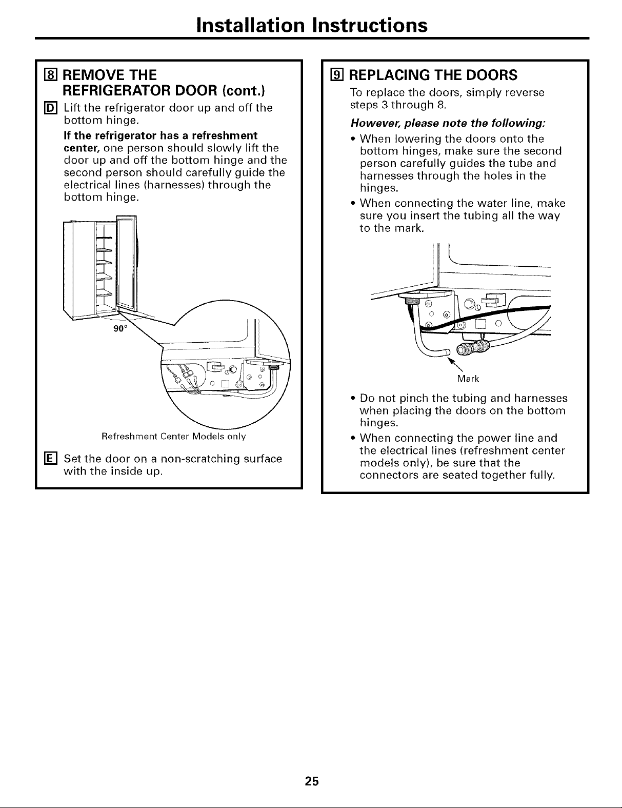
[] REMOVE THE
REFRIGERATOR DOOR (cont.)
[] Lift the refrigerator door up and off the
bottom hinge.
If the refrigerator has a refreshment
center, one person should slowly lift the
door up and off the bottom hinge and the
second person should carefully guide the
electrical lines (harnesses) through the
bottom hinge.
====4===
90°
[] REPLACING THE DOORS
To replace the doors, simply reverse
steps 3 through 8.
However, please note the following:
• When lowering the doors onto the
bottom hinges, make sure the second
person carefully guides the tube and
harnesses through the holes in the
hinges.
• When connecting the water line, make
sure you insert the tubing all the way
to the mark.
Refreshment Center Models only
[] Set the door on a non-scratching surface
with the inside up.
Mark
• Do not pinch the tubing and harnesses
when placing the doors on the bottom
hinges.
• When connecting the power line and
the electrical lines (refreshment center
models only), be sure that the
connectors are seated together fully.
25
Installation Instructions
INSTALLING THE REFRIGERATOR
REFRIGERATOR LOCATION
• Do not install the refrigerator where the
temperature will go below 60°F (16°C)
because it will not run often enough to
maintain proper temperatures.
• Do not install the refrigerator where the
temperature will go above 100°F (37°C)
because it will not perform properly.
• Install it on a floor strong enough to
support it fully loaded.
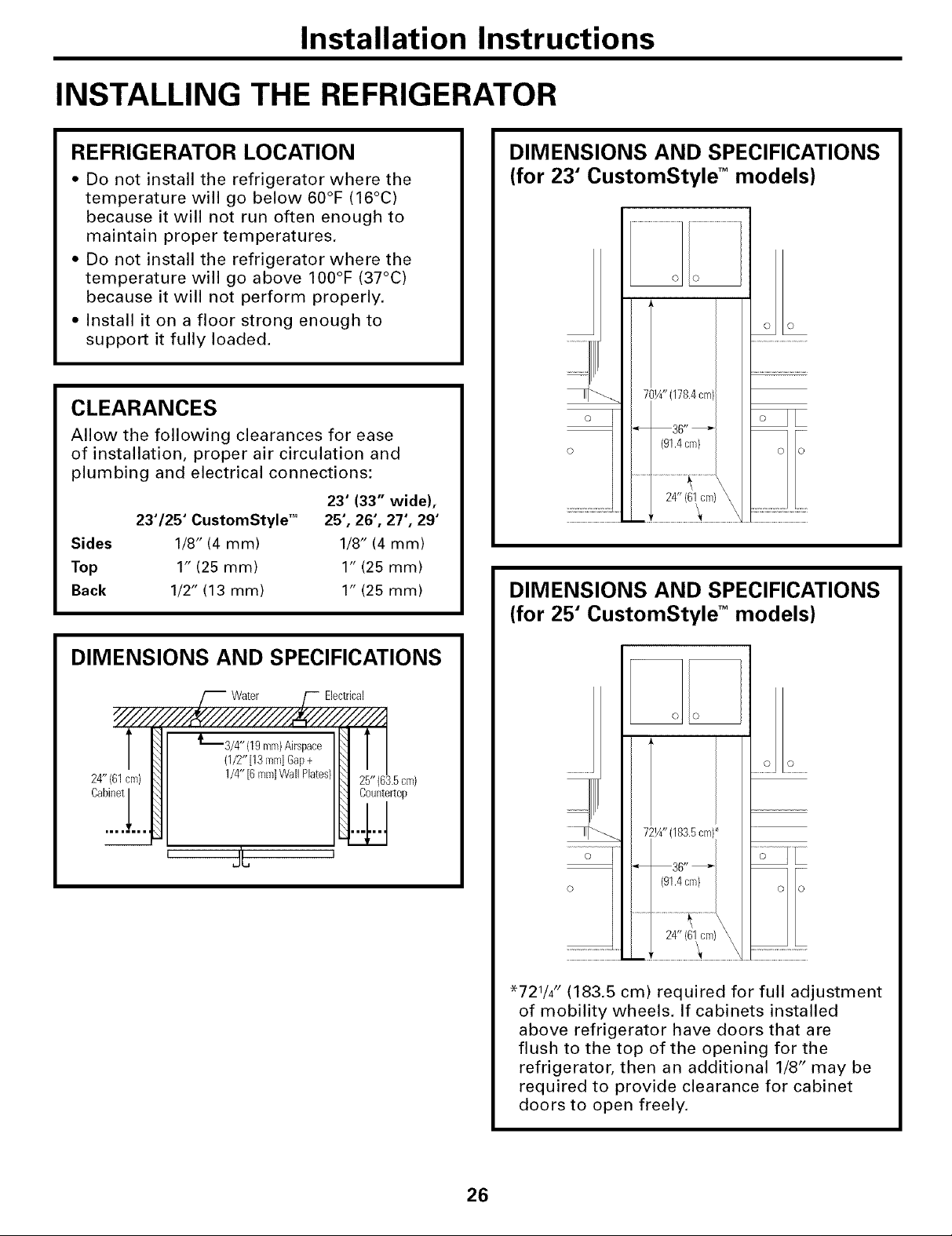
CLEARANCES
Allow the following clearances for ease
of installation, proper air circulation and
plumbing and electrical connections:
23' (33" wide),
23'/25' CustomStyle TM 25', 26', 27', 29'
Sides 1/8" (4 mm) 1/8" (4 mm)
Top 1" (25 mm) 1" (25 mm)
Back 1/2" (13 mm) 1" (25 mm)
DIMENSIONS AND SPECIFICATIONS
(for 23" CustomStyle TM models)
70¼"(178.4cm
o
36"
(91.4cm)
DIMENSIONS AND SPECIFICATIONS
(for 25" CustomStyle TM models)
DIMENSIONS AND SPECIFICATIONS
Water Electrical
_'_3/4" (19ram)Airspace
(1/2"[13 lem]Gap+
1/4" [6ram]WallPlates)
25" (63.5cm)
Countert0p
' J'L '
........2 2 ........
72¼"(183.5cm)_
O
O
"721/4 rl (183.5 cm) required for full adjustment
of mobility wheels. If cabinets installed
above refrigerator have doors that are
flush to the top of the opening for the
refrigerator, then an additional 1/8'I may be
required to provide clearance for cabinet
doors to open freely.
36"
(91.4cm)
26
Installation Instructions
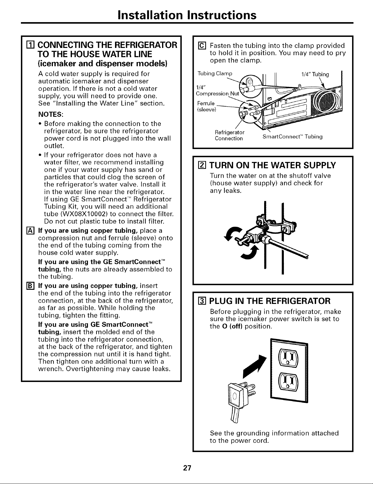
[] CONNECTING THE REFRIGERATOR
TO THE HOUSE WATER LINE
(icemaker and dispenser models)
A cold water supply is required for
automatic icemaker and dispenser
operation. If there is not a cold water
supply, you will need to provide one.
See "Installing the Water Line" section.
NOTES:
Before making the connection to the
refrigerator, be sure the refrigerator
power cord is not plugged into the wall
outlet.
* If your refrigerator does not have a
water filter, we recommend installing
one if your water supply has sand or
particles that could clog the screen of
the refrigerator's water valve. Install it
in the water line near the refrigerator.
If using GE SmartConnect TM Refrigerator
Tubing Kit, you will need an additional
tube (WX08X10002) to connect the filter.
Do not cut plastic tube to install filter.
[] If you are using copper tubing, place a
compression nut and ferrule (sleeve) onto
the end of the tubing coming from the
house cold water supply.
If you are using the GE SmartConnect TM
tubing, the nuts are already assembled to
the tubing.
[] If you are using copper tubing, insert
the end of the tubing into the refrigerator
connection, at the back of the refrigerator,
as far as possible. While holding the
tubing, tighten the fitting.
If you are using GE SmartConnect TM
tubing, insert the molded end of the
tubing into the refrigerator connection,
at the back of the refrigerator, and tighten
the compression nut until it is hand tight.
Then tighten one additional turn with a
wrench. Overtightening may cause leaks.
[] Fasten the tubing into the clamp provided
to hold it in position. You may need to pry
open the clamp.
Tubing Clamp 1/4" Tubin
1/4"
Compression
Ferrule
(sleeve)
Refrigerator
Connection
SmartConnect TM Tubing
[] TURN ON THE WATER SUPPLY
Turn the water on at the shutoff valve
(house water supply) and check for
any leaks.
[] PLUG IN THE REFRIGERATOR
Before plugging in the refrigerator, make
sure the icemaker power switch is set to
the O (off) position.
27
See the grounding information attached
to the power cord.
Installation Instructions
INSTALLING THE REFRIGERATOR (CONT.)
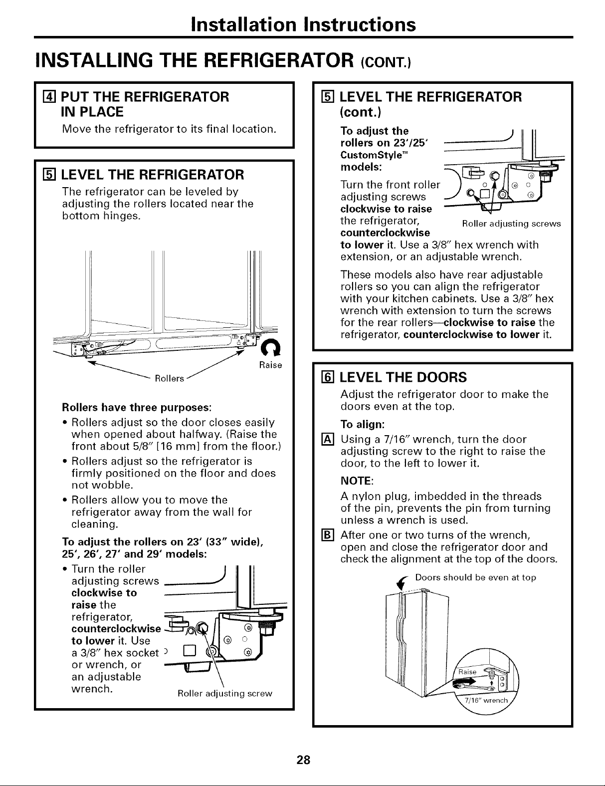
[] PUT THE REFRIGERATOR
IN PLACE
Move the refrigerator to its final location.
[] LEVEL THE REFRIGERATOR
The refrigerator can be leveled by
adjusting the rollers located near the
bottom hinges.
Rollers have three purposes:
• Rollers adjust so the door closes easily
when opened about halfway. (Raise the
front about 5/8" [16 mm] from the floor.)
• Rollers adjust so the refrigerator is
firmly positioned on the floor and does
not wobble.
• Rollers allow you to move the
refrigerator away from the wall for
cleaning.
To adjust the rollers on 23" (33" wide),
25", 26", 27" and 29" models:
Raise
[] LEVEL THE REFRIGERATOR
(cont.)
To adjust the
rollers on 23"/25'
CustomStyle TM
models:
Turn the front roller
adjusting screws
clockwise to raise
the refrigerator, Roller adjusting screws
counterclockwise
to lower it. Use a 3/8" hex wrench with
extension, or an adjustable wrench.
These models also have rear adjustable
rollers so you can align the refrigerator
with your kitchen cabinets. Use a 3/8" hex
wrench with extension to turn the screws
for the rear rollersiclockwise to raise the
refrigerator, counterclockwise to lower it.
[] LEVEL THE DOORS
Adjust the refrigerator door to make the
doors even at the top.
To align:
[]
Using a 7/16" wrench, turn the door
adjusting screw to the right to raise the
door, to the left to lower it.
NOTE:
A nylon plug, imbedded in the threads
of the pin, prevents the pin from turning
unless a wrench is used.
[]
After one or two turns of the wrench,
open and close the refrigerator door and
check the alignment at the top of the doors.
adjusting screws
clockwise to - ....
•
raise the
to lower it. Use
r r0er tor
a 3/8" hex socket
or wrench, or
counterclockwise .___J_
an adjustable
wrench. Roller adjusting screw
Doors should be even at top
28
Installation Instructions
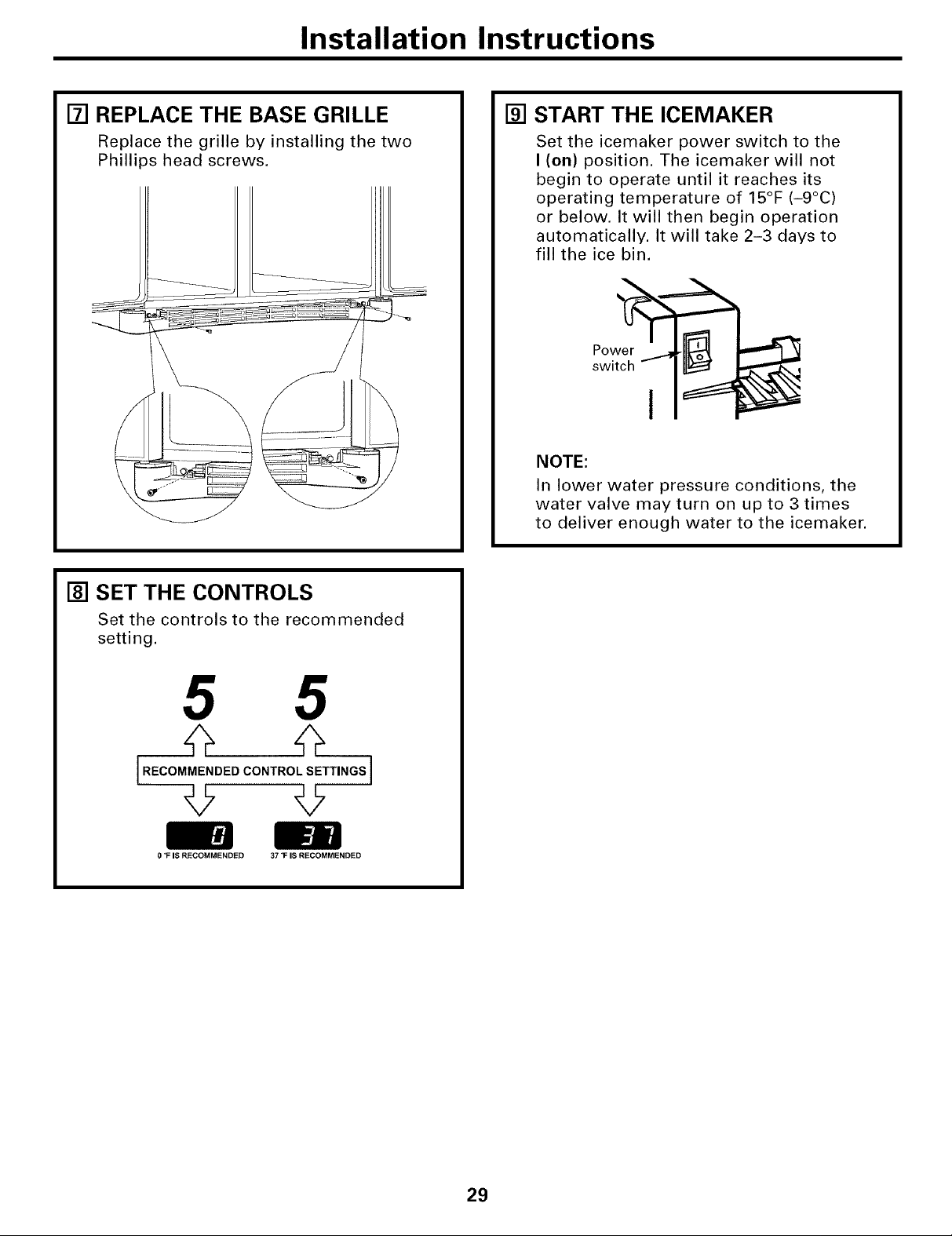
[] REPLACE THE BASE GRILLE
Replace the grille by installing the two
Phillips head screws.
[] START THE ICEMAKER
Set the icemaker power switch to the
I (on) position. The icemaker will not
begin to operate until it reaches its
operating temperature of 15°F (-9°C)
or below. It will then begin operation
automatically. It will take 2-3 days to
fill the ice bin.
Pow
switch - I _"
NOTE:
In lower water pressure conditions, the
water valve may turn on up to 3 times
to deliver enough water to the icemaker.
[] SET THE CONTROLS
Set the controls to the recommended
setting.
5 5
[.EOOMME.0E0CO.T.O'SETT..OS]
0 1: IS RECOMMENDED 37 "F IS RECOMMENDED
29
Installation Instructions
INSTALLING THE WATER LINE (ICEMAKER &DISPENSERMODELS)
BEFORE YOU BEGIN
Recommended copper water supply kits are
WX8X2, WX8X3 or WX8X4, depending on the
amount of tubing you need. Approved plastic
water supply lines are GE SmartConnect TM
Refrigerator Tubing (WX08X10002,
WX08X10006, WX08X10015 and
WX08X 10025).
When connecting your refrigerator to a GE
Reverse Osmosis Water System, the only
approved installation is with a GE RVKit. For
other reverse osmosis water systems, follow
the manufacturer's recommendations.
If the water supply to the refrigerator is from
a Reverse Osmosis Water Filtration System
AND the refrigerator also has a water filter,
use the refrigerator's filter bypass plug. Using
the refrigerator's water filtration cartridge in
conjunction with the RO filter can result in
hollow ice cubes and slower water flow from
the water dispenser.
This water line installation is not warranted
by the refrigerator or icemaker manufacturer.
Follow these instructions carefully to
minimize the risk of expensive water damage.
Water hammer (water banging in the pipes)
in house plumbing can cause damage to
refrigerator parts and lead to water leakage
or flooding. Call a qualified plumber to correct
water hammer before installing the water
supply line to the refrigerator.
To prevent burns and product damage, do not
hook up the water line to the hot water line.
If you use your refrigerator before connecting
the water line, make sure the icemaker power
switch is in the O (off) position.
Do not install the icemaker tubing in areas
where temperatures fall below freezing.
When using any electrical device (such as a
power drill) during installation, be sure the
device is double insulated or grounded in a
manner to prevent the hazard of electric
shock, or is battery powered.
All installations must be in accordance with
local plumbing code requirements.
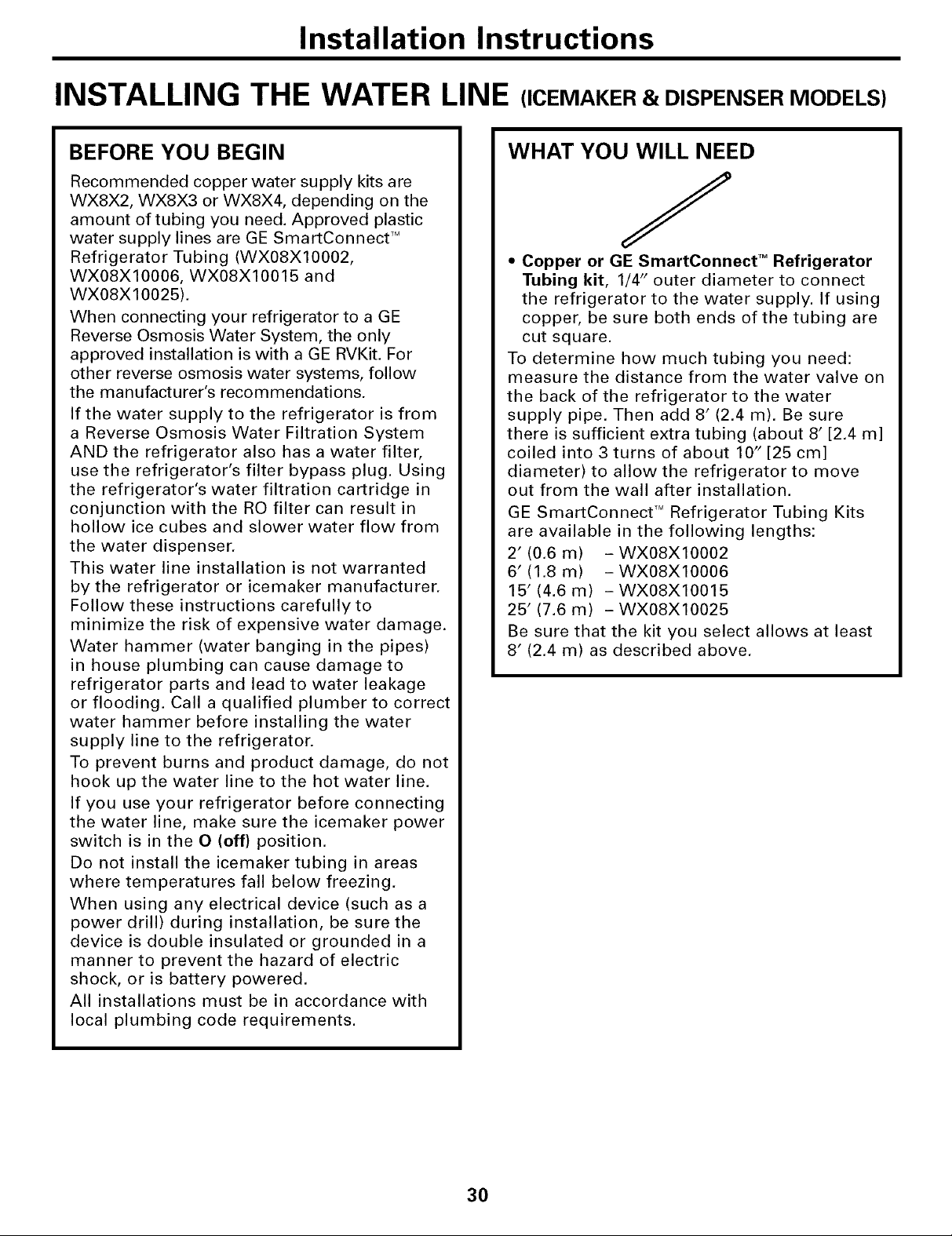
WHAT YOU WILL NEED
J
• Copper or GE SmartConnect TM Refrigerator
Tubing kit, 1/4" outer diameter to connect
the refrigerator to the water supply. If using
copper, be sure both ends of the tubing are
cut square.
To determine how much tubing you need:
measure the distance from the water valve on
the back of the refrigerator to the water
supply pipe. Then add 8' (2.4 m). Be sure
there is sufficient extra tubing (about 8' [2.4 m]
coiled into 3 turns of about 10" [25 cm]
diameter) to allow the refrigerator to move
out from the wall after installation.
GE SmartConnect TMRefrigerator Tubing Kits
are available in the following lengths:
2' (0.6 m) - WX08X10002
6' (1.8 m) -WX08X10006
15' (4.6 m) - WX08X10015
25' (7.6 m) - WX08X10025
Be sure that the kit you select allows at least
8' (2.4 m) as described above.
30
 Loading...