

GE PSC21MGM, PSI21MGM, PSC23MGM, PSI23MGM Technical Service Manual

!
IMPORTANT SAFETY NOTICE
The information in this service guide is intended for use by
individuals possessing adequate backgrounds of electrical,
electronic, and mechanical experience. Any attempt to repair a
major appliance may result in personal injury and property
damage. The manufacturer or seller cannot be responsible for the
interpretation of this information, nor can it assume any liability in
connection with its use.
WARNING
To avoid personal injury, disconnect power before servicing this
product. If electrical power is required for diagnosis or test
purposes, disconnect the power immediately after performing the
necessary checks.
RECONNECT ALL GROUNDING DEVICES
If grounding wires, screws, straps, clips, nuts, or washers used
to complete a path to ground are removed for service, they must
be returned to their original position and properly fastened.
GE Consumer Home Services Training
Technical Service Guide
Copyright © 2001
All rights reserved. This service guide may not be reproduced in whole or in part
in any form without written permission from the General Electric Company.

Table of Contents
Introduction . . . . . . . . . . . . . . . . . . . . . . . . . . . . . . . . . . . . . . . . . . . . . . . . . . . . . . 2
Installation . . . . . . . . . . . . . . . . . . . . . . . . . . . . . . . . . . . . . . . . . . . . . . . . . . . . . . . 3
Specifications . . . . . . . . . . . . . . . . . . . . . . . . . . . . . . . . . . . . . . . . . . . . . . . . . . . . 4
Nomenclature . . . . . . . . . . . . . . . . . . . . . . . . . . . . . 5
Warranty Information . . . . . . . . . . . . . . . . . . . . . . . . . . . . . 6
Operating Characteristics . . . . . . . . . . . . . . . . . . . . . . . . . . . . . . 7
General Locator Views . . . . . . . . . . . . . . . . . . . . . . . . . . . . . . . . . . . . . . . . . . . . . 14
Mechanical Disassembly . . . . . . . . . . . . . . . . . . . . . . . . . . . . . . . . . . . . . . . . . . . 16
Diagnostics . . . . . . . . . . . . . . . . . . . . . . . . . . . . . . . . . . . . . . . . . . . . . . . . . . . . . . 32
Component and Connector Locator Views . . . . . . . . . . . . . . . . . . . . . . . . . . . . 55
Schematics and Strip Circuits . . . . . . . . . . . . . . . . . . . . . . . . . . . . . . 61
Illustrated Parts Catalog . . . . . . . . . . . . . . . . . . . . . . . . . . . . . . 63
– 1 –
Introduction
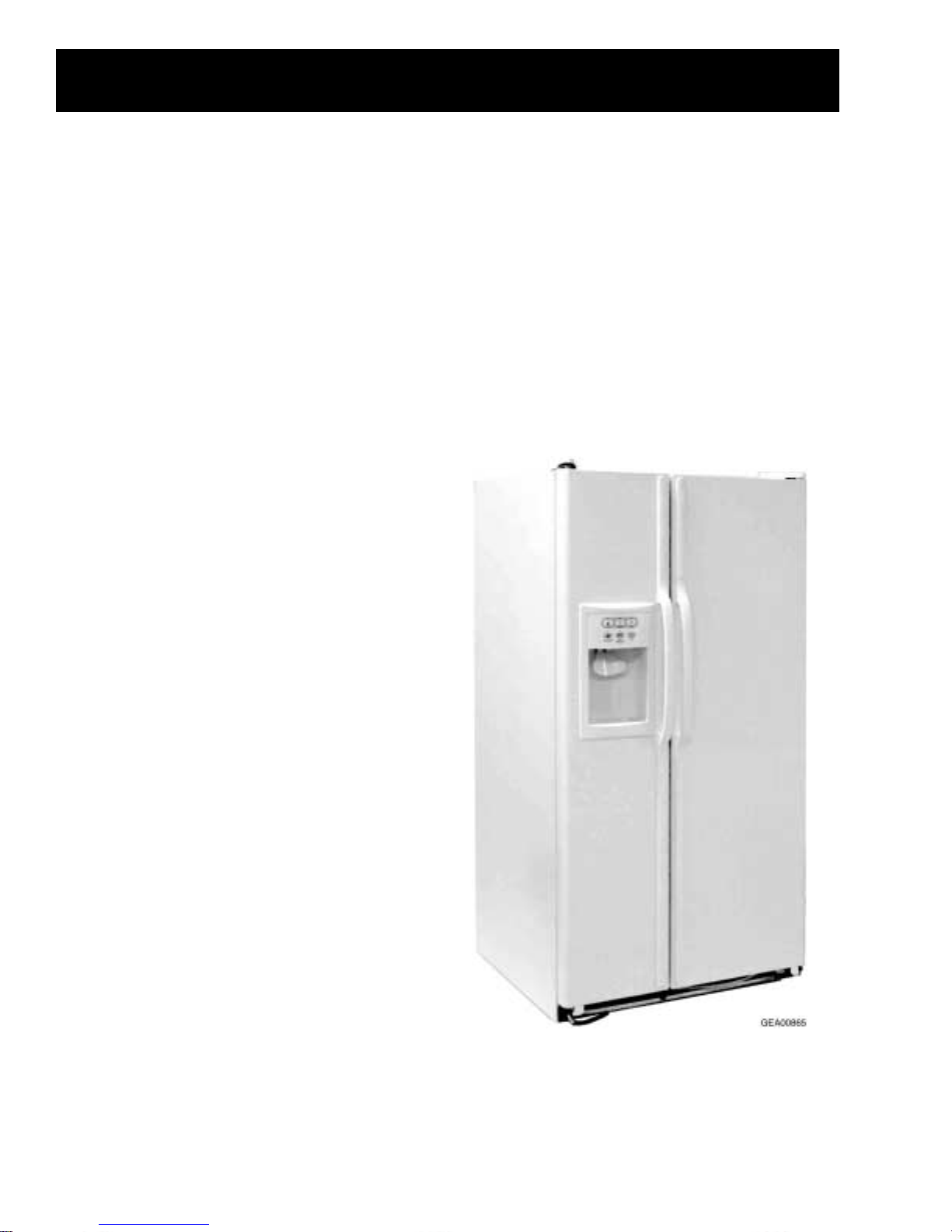
2001 Energy SxS models are being introduced in
response to the requirement for more energyefficient refrigerators by mid year 2001, along with
feature and operation enhancements. The primary
differences in this refrigeration system are the
adaptive defrost system (see Pub # 31-9062),
control board, software, and control systems that
operate independently in fresh food and freezer
sections. The new high-efficiency control system
has the ability to cycle components and adjust fan
speeds as required to maintain temperaturesetting ranges in fresh food and freezer sections.
Feedback systems are digital inputs and relay
outputs. Sensors (thermistors) are used to
measure temperature with communications to a
main PC board, which controls the unit
components.
The Refrigerator has touchpad controls to provide
inputs to a microprocessor. The fresh food and
freezer controls are temperature setpoint type and
have settings of 0-9 with 9 being the coldest
temperature possible. The new NO CLEAN
condenser is serviceable from the rear and is
designed to prevent the customer from having to
clean the condenser in normal usage conditions.
The freezer has adjustable shelves, a slide-out
Spillproof shelf, a QuickSpace shelf, and deep
door shelves, based on the model. The fresh food
section has a baking soda holder, a fruit and
vegetable drawer, drawer dividers, an adjustable
humidity drawer, and a convertible meat drawer.
The new high-efficiency refrigerator is a
combination of the most efficient refrigeration
system and the most desirable customer features
available.
Sealed system operation and compressor are
functionally the same as previous models, with
some minor changes.
The Profile Perfomance and Arctica side by side
models are the models affected. These models are
available with a through-the-door chilled water and
ice dispenser, and a built-in water filter feature. On
models requiring icemaker, the newest electronic
icemaker (see Pub. # 31-9063) has been or can
be installed.
– 2 –
Installation
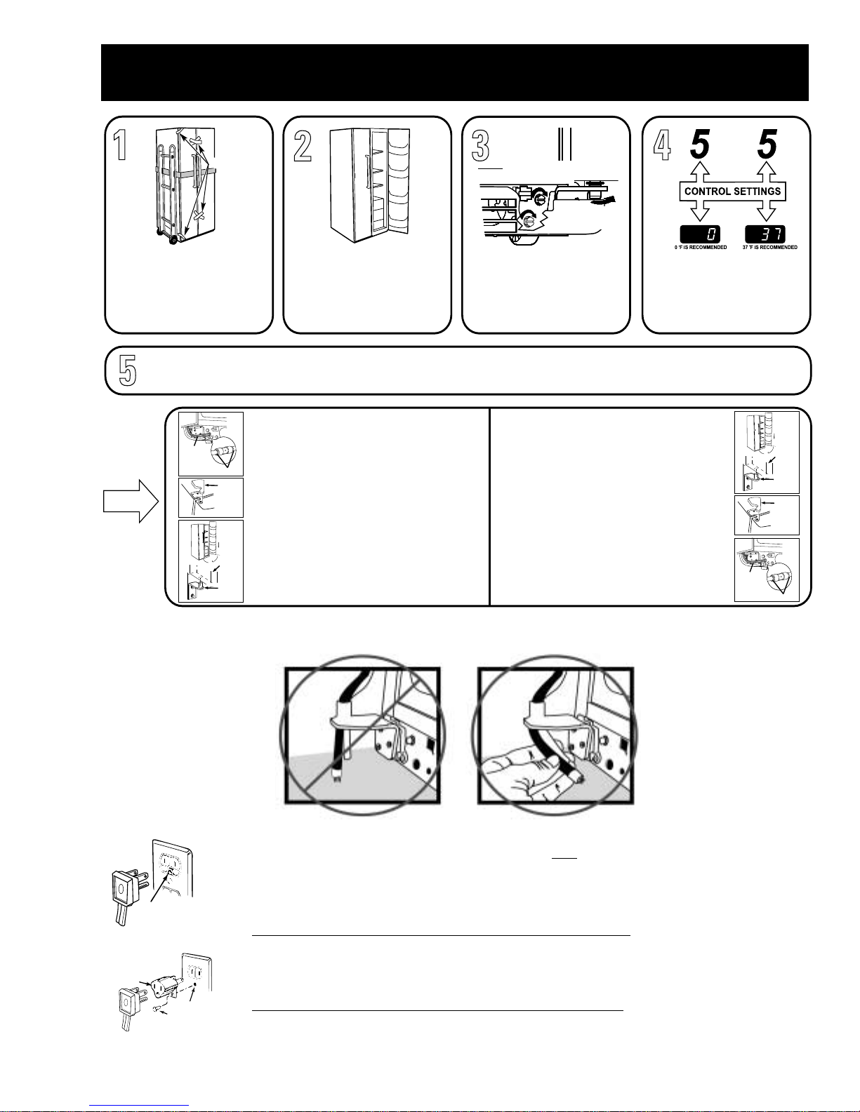
Use padded hand truck to protect
refrigerator finish. LEAVE TAPE
ON DOORS until refrigerator is in
its final location. TRUCK FROM
SIDE ONLY. Avoid overtightening
strap to prevent damaging doors.
REMOVE ALL CLEAR PROTECTIVE
TAPE FROM TRIMS, then move unit
into position. If entrance is less
than 38″ wide, remove doors prior
to installation and reinstall doors
according to procedure below.
Connect water lines and power cord.
ADJUST FRONT ROLLERS so the
refrigerator is solid on floor and
doors close easily. MAKE SURE
DOORS ARE EVEN AT TOP.
TEMPERATURE CONTROLS ARE
PRESET IN THE FACTORY FOR
RECOMMENDED SETTINGS.
• APPLIANCE POLISH WAX IS RECOMMENDED FOR REMOVING TAPE RESIDUE AND HAND PRINTS FROM REFRIGERATOREXTERIOR.
• REMOVE ALL TAPE ANDOTHER PACKAGING MATERIAL FROM REFRIGERATOR INTERIOR. DO NOT REMOVE SERIAL PLATE.
• REMOVE PROTECTIVE FILM ON TEMPERATURE CONTROL PANEL.
ROLLER HEIGHT
ADJUSTMENT
NOTICE
TAPE
DOOR HEIGHT
ADJUSTMENT
Doors should be in closed position. Near lower hinge
on freezer side, squeeze collar on water line and pull
tubing from coupling. Also, disconnect wiring harness.
Pull water line and harness through lower rail.
Remove top hinge covers to access hinges. Remove
hinges using a Torx T-20.
Carefully rotate door through 90°. Guiding water line
and wiring harness, lift door straight up. Avoid side
loading the bottom hinges. Place doors on a protective
surface. Avoid pinching the water tube and wire
harness at the bottom of the door.
Removing Doors
With Doors 90° open, place doors on bottom hinge.
Carefully rotate doors to closed position. Avoid side
loading the bottom hinges.
Reinstall top hinges and tighten screws firmly.
Reinstall hinge cover. If doors are not level, adjust
bottom right hinges with a
7
⁄16″ open ended wrench.
Insert water tubing back into coupling. It is completely
connected when the mark on the tubing is no longer
visible. Reconnect wire harness. Turn on water supply.
Re-installing Doors
90
HINGE
COVER
DOOR
HINGE
PIN
WIRE
HARNESS
COLLARS
90
HINGE
COVER
DOOR
HINGE
PIN
WIRE
HARNESS
COLLARS
IMPORTANT: PLEASE READ CAREFULLY
FOR PERSONAL SAFETY, THIS APPLIANCE MUST BE PROPERLY GROUNDED.
The power cord of this appliance is equipped with a three-prong (grounding) plug that mates with a standard three-prong (grounding) wall receptacle to minimize the
risk of electric shock hazard from this appliance. The customer should have the wall receptacle and circuit checked by a qualified electrician to make sure the receptacle
is properly grounded.
Where a standard two-prong wall receptacle is encountered, it is the personal responsibility and obligation of the customer to have it replaced with a properly grounded
three-prong wall receptacle.
DO NOT, UNDER ANY CIRCUMSTANCES, CUT OR REMOVE THE THIRD (GROUND) PRONG FROM THE POWER CORD.
USAGE
SITUATIONS WHERE THE APPLIANCE’S POWER CORD WILL BE DISCONNECTED INFREQUENTLY
Because of potential safety hazards under certain conditions, we strongly recommend against the use of an adapter plug. However, if you still elect to use an adapter,
where local codes permit, a TEMPORARY CONNECTION may be made to a properly grounded two-prong wall receptacle by the use of a UL listed adapter which is
available at most hardware stores. The larger slot of the adapter must be aligned to provide proper polarity in the connection of the power cord.
CAUTION: Attaching the adapter ground terminal to the wall receptacle cover screw does not ground the appliance unless the cover screw is metal, and not insulated,
and the wall receptacle is grounded through the house wiring. The customer should have the circuit checked by a qualified electrician to make sure the receptacle is
properly grounded. When disconnecting the power cord from the adapter, always hold the adapter with one hand. If this is not done, the adapter ground terminal is very
likely to break with repeated use. Should this happen, DO NOT USE the appliance until a proper ground has again been established.
USAGE
SITUATIONS WHERE THE APPLIANCE’S POWER CORD WILL BE DISCONNECTED FREQUENTLY
Do not use an adapter plug in these situations because frequent disconnecting of the power cord places undue strain on the adapter and leads to eventual failure of the
adapter ground terminal. The customer should have the two-prong wall receptacle replaced with a three-prong (grounding) receptacle by a qualified electrician before
using the appliance.
MAKE SURE PROPER
GROUND EXISTS
BEFORE USE
PREFERRED
METHOD
ENSURE PROPER
GROUND AND
FIRM CONNECTION
TEMPORARY METHOD
(Adapter plugs not
permitted in Canada)
CAUTION: Do NOT allow the connector to contact the floor. Hard contact can damage the connector.
– 3 –
Specifications
DISCONNECT POWER CORD BEFORE SERVICING
IMPORTANT-RECONNECT ALL GROUNDING DEVICES
All parts of this appliance capable of conducting electrical
current are grounded. If grounding wires, screws, straps,
clips, nuts or washers used to complete a path to ground
are removed for service, they must be returned to
their original position and properly fastened.
ELECTRICAL SPECIFICATIONS
Temperature Control {Position 5) ................. 7-(-11 )°F
Defrost Control ............................................. 60hrs @ 35 min
Overtemperature Thermostat....................... 140-110°F
w/ no door openings
Defrost Thermistor ....................................... 65°F
Electrical Rating: 115V. AC 60 Hz................ 11.6 Amp
Maximum Current Leakage.......................... 0.50 mA.
Maximum Ground Path Resistance ............. 0.14 Ohms
Energy Consumption ................................... KWH/mo.
NO LOAD PERFORMANCE
Control Position MID/MID
and Ambient of:
70°F 90°F
Fresh Food, °F ...........................................34-40 34-40
Frozen Food, °F .........................................(-3) 3 (-3) 3
Run Time, %...............................................<45% <70%
IMPORTANT SAFETY NOTICE
This information is intended for use by individuals
possessing adequate backgrounds of electrical,
electronic and mechanical experience. Any attempt
to repair a major appliance may result in personal
injury and property damage. The manufacturer or
seller cannot be responsible for the interpretation
of this information, nor can it assume any liability
in connection with its use.
INSTALLATION
Clearance must be provided for air circulation
A T TOP........................................................................1”
AT SIDES ....................................................................1/8”
A T REAR..................................................................... 1”
AIR FLOW
REFRIGERA TION SYSTEM
Refrigerant Charge (R134a) ....................... 4.75 ounces
Compressor ................................................. 690 BTU/hr
Minimum Compressor Capacity ................... 22 inches
Minimum Equalized Pressure
@ 70°F......................................................... 48 PSIG
@ 90°F......................................................... 60 PSIG
MODELS
PSC21MGM PSI21MGM
PSC23MGM PSI23MGM
REPLACEMENT PAR TS
T emperature Control ............................................... wr55x10023
Relay....................................................................... wr07x10031
Overload................................................................. wr08x10025
Run Capacitor (12
Overtemperature Thermostat ................................ wr50x10015
Defrost Heater Harness & Thermostat ................. wr23x10142
Defrost Heater & Bracket ........................................ wr51x10030
Condenser Fan Motor ............................................. wr60x10042
Evaporator Fan Motor ............................................. wr60x10043
Main Board.............................................................. wr55x10024
Dispenser Board ..................................................... wr55x10029
Thermistor (EV)....................................................... wr55x10025
Thermistor (FZ) ....................................................... wr55x10026
Thermistor (FF) ....................................................... wr55x10027
Thermistor (FF) ..................................................... wr55x10028
FF Fan Motor .......................................................... wr60x10051
Damper................................................................... wr60x10052
u
F)............................................ wr62x10079
– 4 –
Profile 2001 Models
Nomenclature
CONFIGURATION
S = SIDE-BY-SIDE REF.
VOLUME
23 / 25 / 27 / 29
MODEL YEAR
M = 2001
ENGINEERING
NOMENCLATURE
A = INITIAL DESIGN
B = 1ST REVISION
ETC.
P S S 2 5 I E M A F W W
BRAND/PRODUCT
G = GE
H = HOTPOINT
P = PROFILE (GE)
E = ETERNA (GE)
R = RCA
S = SELECT (GE)T
DEPTH/POWER
S = STANDARD
T = TROPICAL
G = GLOBALT
INTERIOR/SHELVES
D = DELUXE WIRE
I = DELUXE GLASS
J = PREMIUM GLASS
K = SPILLPROOF GLASS
M = SPILLPROOF/SLIDE-OUT
GLASS & QUICKSPACE
Q = SHOWCASE DERIVATIVE
S = STAINLESS STEEL DOORS
U = ABV DERIVATIVE
V = SEARS DERIVATIVE
W = HPS (CONTRACT )
DERIVATIVE
X = REGIONAL DERIVATIVE
ICEMAKER/EXTERIOR
B = NON-DISPENSER/ICEMAKER READY
D = CUBED ICE/WATER
E = CUBED & CRUSHED ICE/ WATER
F = 6 MO. FILTER/CUBED & CRUSHED ICE
G = 1 YR. FILTER/CUBED & CRUSHED ICE
I = IN-LINE FILTER/INDICATOR & C/C/W
DOOR TYPE
F = FLAT DOOR (G-LINE)
(SPACE = FLAT DOOR (S-
& T-LINE
K = RETRO-FIT DOOR
EXTERIOR COLOR
WW = WHITE/WHITE
AA = ALMOND/ALMOND
BB = BLACK/BLACK
CC = BISQUE/BISQUE
WH = WHITE/BLACK
BS = BLACK/STAINLESST
– 5 –
Warranty Information
Sales slip or cancelled check is required as proof of original purchase date to obtain service
under warranty.
All warranty service is provided by our Factory Service Centers or an authorized Customer Care®
technician.
:fOdoirePehTroF :ecalpeRlliWEG
raeYenO
ehtfoetadehtmorF
esahcruplanigiro
sraeYeviF
ehtfoetadehtmorF
esahcruplanigiro
emitefiL
ehtfoetadehtmorF
esahcruplanigiro
syaDytrihT
foetadehtmorF
eht
esahcruplanigiro
trapynA sliafhcihw)egdirtracretlifretawgnidulcxe(rotaregirferehtfo
,ytnarraw ,edivorposlalliwEG ,egrahcfoeerf emoh-nidnaroballla
,edivorposlalliw ,egrahcfoeerf ecalperotecivresemoh-nidnaroballla
.trapevitcefedeht
.dedulcni
trapynA nitcefedaoteudsliafhcihwegdirtracretlifretawehtfo
,edivorposla ,egrahcfoeerf ehtecalperotecivresemoh-nidnaroballla
.trapevitcefed
:revoCtoNlliWEGtahW
• Service trips to your home to teach you
how to use the product.
• Improper installation.
• Failure of the product if it is abused or
used for other than the intended purpose
or used commercially.
• Loss of food due to spoilage.
• Replacement of house fuses or resetting of
circuit breakers.
sihtgniruD.pihsnamkrowroslairetamnitcefedaoteud raey-enolluf
.trapevitcefedehtecalperotecivres
metsysgnitaregirferdelaesehtfotrapynA ,rosserpmoceht(
aoteudsliafhcihw)gnibutgnitcennoclladna,rotaropave,resnednoc
sihtgniruD.pihsnamkrowroslairetamnitcefed ,ytnarrawraey-evif EG
rewardronaphguorht-eesynA napehtfirotaregirferehthtiwdehsinruf
tonerasrevocrewarD.esudlohesuohlamrongnirudskaerbrewardro
sihtgniruD.pihsnamkrowroslairetam ,ytnarrawyad-ytrihtlluf lliwew
• Replacement of the water filter cartridge
due to water pressure that is outside the
specified operating range or due to excessive sediment in the water supply.
• Replacement of water filter cartridge after
its expected useful life, 30 days.
• Damage to the product caused by accident,
fire, floods, or acts of God.
• Incidental or consequential damage caused
by possible defects with this appliance.
This warranty is extended to the original purchaser and any succeeding owner for products purchased
for home use within the USA. In Alaska, the warranty excludes the cost of shipping or service calls to
your home.
Some states do not allow the exclusion or limitation of incidental or consequential damages. This warranty gives you specific legal rights, and you may also have other rights which vary from state to state.
To know what your legal rights are, consult your local or state consumer affairs office or your state’s
Attorney General.
Warrantor: General Electric Company. Louisville, KY 40225
– 6 –

Operating Characteristics
Table of Contents
Fresh Food/Freezer Independent Operation . . . . . . . . . . . . . . . . . . . . . . . . . . . . 8
Normal Operating Characteristics, but Different from Previous Models
Abnormal Operating Characteristics (Incorrect Operation) . . . . . . . . . . . . . . . . 8
Adaptive Defrost . . . . . . . . . . . . . . . . . . . . . . . . . . . . . . . . . . . . . . . . . . . . . . . . . . . 8
Cooling Operation (Adaptive Defrost) . . . . . . . . . . . . . . . . . . . . . . . . . . . . . . . . . 9
Pre-Chill Operation (Adaptive Defrost). . . . . . . . . . . . . . . . . . . . . . . . . . . . . . . . . 9
Defrost Heater Operation (Adaptive Defrost). . . . . . . . . . . . . . . . . . . . . . . . . . . . 9
Dwell Period (Adaptive Defrost) . . . . . . . . . . . . . . . . . . . . . . . . . . . . . . . . . . . . . . 9
Post Dwell (Adaptive Defrost) . . . . . . . . . . . . . . . . . . . . . . . . . . . . . . . . . . . . . . . . 9
Liner Protection Mode . . . . . . . . . . . . . . . . . . . . . . . . . . . . . . . . . . . . . . . . . . . . . . 9
Electronic Icemaker . . . . . . . . . . . . . . . . . . . . . . . . . . . . . . . . . . . . . . . . . . . . . . . . . . . . . . . . 10
Dispensing Functions . . . . . . . . . . . . . . . . . . . . . . . . . . . . . . . . . . . . . . . . . . . . . . 10
. . . . . . . 8
Quick Ice . . . . . . . . . . . . . . . . . . . . . . . . . . . . . . . . . . . . . . . . . . . . . . . . . . . . . . . . 10
Door Alarm . . . . . . . . . . . . . . . . . . . . . . . . . . . . . . . . . . . . . . . . . . . . . . . . . . . . . . 10
Dispenser Light . . . . . . . . . . . . . . . . . . . . . . . . . . . . . . . . . . . . . . . . . . . . . . . . . . . 10
Dispenser Lock . . . . . . . . . . . . . . . . . . . . . . . . . . . . . . . . . . . . . . . . . . . . . . . . . . . 10
Filters . . . . . . . . . . . . . . . . . . . . . . . . . . . . . . . . . . . . . . . . . . . . . . . . . . . . . . . . . . . 11
Hinge System and Door Closure . . . . . . . . . . . . . . . . . . . . . . . . . . . . . . . . . . . . . 11
Airflow (Cabinet Interior) . . . . . . . . . . . . . . . . . . . . . . . . . . . . . . . . . . . . . . . . . . . 11
“Jelly Roll” Condenser . . . . . . . . . . . . . . . . . . . . . . . . . . . . . . . . . . . . . . . . . . . . . 12
Main Control Board . . . . . . . . . . . . . . . . . . . . . . . . . . . . . . . . . . . . . . . . . . . . . . . . . . . . . . . .13
– 7 –

Fresh Food/Freezer Independent
Operation
Abnormal Operating Characteristics
(Incorrect Operation)
In previous models, the fresh food and freezer
compartment components worked at the same
time. When the fresh food compartment called for
cold air, the freezer compartment components
would work with the fresh food compartment
components. This is called nonindependent
operation.
In this model, the fresh food compartment
components can operate without the freezer
compartment components operating. This is called
independent operation.
Normal Operating Characteristics that May
Occur, but Different from Previous Models
• Icemaker auger rotates clockwise.
• Evaporator fan running, without compressor or
condenser fan. Fresh food fan is on.
• Post dwell (adaptive defrost), compressor and
condenser fan on with evaporator fan off after
defrost cycle.
• Liner Protection Mode, fans come on when the
doors are open for 3 minutes.
• When the doors open, the fans shut off.
• Fresh food fan on and evaporator fan off.
• Evaporator fan on, fresh food fan and
compressor off, and damper shut.
• Rapid fan speed changes, fan takes at least 1
minute to change speeds.
• Compressor running without the condenser fan.
The compressor and condenser fan should
always run at the same time.
• Condenser fan running without the
compressor. The compressor and condenser
fan should always run at the same time.
Adaptive Defrost
Adaptive defrost can be described as a defrost
system that adapts to a refrigerator’s surrounding
environment and household usage.
Unlike conventional defrost systems that use
electromechanical timers with a fixed defrost cycle
time, adaptive defrost utilizes an intelligent,
electronic control to determine when the defrost
cycle is necessary. In order to accomplish the
correct defrost cycle time, the main control board
monitors the following refrigerator operations:
• No airflow to the fresh food compartment when
the evaporator fan is on.
• Evaporator fan and compressor can run
continuously for 8 hours.
• Fans shift speeds, different sound levels can
be noticed when this happens.
• Quick Ice mode, the evaporator fan runs for 48
hours non-stop.
• Response time for drastic temperature change
is 2 to 10 minutes. The main control board will
only respond to 8 degrees of temperature
change per minute as determined by
resistance change of sensor.
• Length of time the refrigerator doors were open
since the last defrost cycle.
• Length of time the compressor has run since
the last defrost cycle.
• Amount of time the defrost heaters were on in
the last defrost.
Adaptive defrost is divided into 5 separate cycles.
Those operations are:
• Cooling Operation
• Pre-Chill Operation
• Defrost Heater Operation
• Dwell Period
• Post dwell
Refer to Pub # 31-9062 for more information about
Adaptive Defrost.
– 8 –
Cooling Operation (Adaptive Defrost)
During the cooling operation, the main control
board monitors door opening (fresh food and
freezer doors) and compressor run times. The
length of time between consecutive defrosts is
reduced by each door opening. If the doors are not
opened, the compressor will run up to 60 hours
between defrosts. If the doors are opened
frequently and/or for long periods of time, the
compressor run time between defrosts will be
reduced to as little as 8 hours.
Pre-Chill Operation (Adaptive Defrost)
When the main control board determines that
defrost is necessary, the main control board will
force the refrigerator into a continuous cool mode
(pre-chill). During pre-chill, the freezer temperature
may be driven below the temperature control panel
display setpoint. However, the fresh food
temperature will be regulated by the damper. Prechill will last for 2 hours if it is not interrupted by
any door openings. If, after 8 hours, the unit has
been unable to complete an uninterrupted pre-chill,
it will proceed to the defrost cycle.
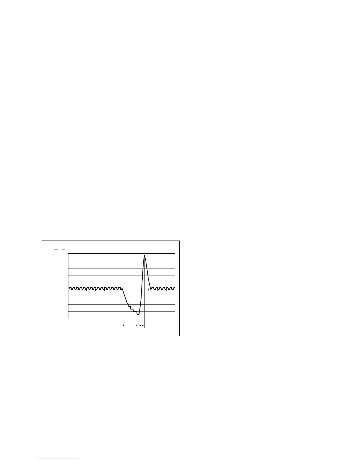
Defrost Heater Operation (Adaptive Defrost)
F
F˚ / C˚
R
E
25˚ / -4˚
E
Z
20˚ / -7˚
E
R
15˚ / -9˚
A
10˚ / -12˚
I
R
5˚ / -15˚
T
E
0˚ / -18˚
M
P
-5˚ / -21˚
E
R
-10˚ / -23˚
A
T
U
-15˚ / -26˚
R
E
-20˚ / -29˚
S
After 2 hours of pre-chill operation or 8 hours of
interrupted pre-chill attempts, the main control
board turns the compressor, condenser fan, and
evaporator fan off. The main control board then
energizes the defrost relay, which completes the
defrost circuit.
During defrost operation, the main control board
monitors the evaporator temperature using
evaporator thermistor inputs. The thermistor will
terminate defrost heater operation usually in less
PRE-CHILL MODE
09:00
08:00
10:00
11:00
12:00
13:00
14:00
15:00
16:00
17:00
18:00
DefrostPre-Chill
than 20 minutes. Typical defrost time is 20-30
minutes.
The defrost system is protected by a defrost
thermostat (switch). The thermostat opens when
the evaporator temperature raises to 140°
Fahrenheit and closes when the evaporator
temperature lowers to 110 degrees Fahrenheit.
Dwell Period (Adaptive Defrost)
After defrost heater operation has been terminated
by the main control board, a 5-minute dwell period
occurs. During this period, the compressor, the
condenser fan, and the evaporator fan remain off.
The remaining frost melting from the evaporator
will continue to drip and drain so the evaporator
will be totally clear of any moisture prior to the
cooling operation. After the 5 minute dwell period,
the unit goes into post dwell.
Post Dwell (Adaptive Defrost)
The post dwell period is designed to cool the
evaporator before circulating air within the
refrigerator. This prevents any residual heat on
the evaporator from being distributed in the
freezer. During this period, the compressor and
condenser fan are on, but all interior fans are off
and the damper is closed. Post dwell times vary
with different models. However, there is a 5minute maximum post dwell time.
Liner Protection Mode
The liner protection mode will activate if either of
the doors have been open for 3 minutes. This
mode will start the fans and close the damper.
This mode is controlled by 2 timers. Timer #1
monitors door-open time. A 3-minute door-open
count begins when the door is opened. If 3
minutes elapse before the door is closed, the liner
protection mode will become active. Once the
door is closed, timer #1 resets and liner protection
mode goes into standby.
In standby, normal fan and damper operations
resume and timer #2 begins a 3-minute doorclosed count. If 3 minutes elapse without a door
opening, liner protection mode will completely
deactivate. If a door is opened within the timer #2
door-closed count, the remaining time in the doorclosed count will be deducted from the timer #1
door-open count.
– 9 –

Electronic Icemaker
Door Alarm
This refrigerator is equipped with an Electronic
Icemaker. Refer to Pub # 31-9063 for more
information.
Dispensing Functions
The water, crushed ice, and cubed ice functions
are controlled by the main control board. To select
a function, press the appropriate pad on the
dispenser. The LED will light to identify the
selection.
To dispense the selected item, depress the
dispenser cradle located in the dispenser recess.
The solenoid and linkage assembly will open the
ice chute door to dispense the ice. If cubed ice is
selected, the crushed ice bypass solenoid will
allow cubed ice to bypass the ice crusher. The ice
chute door must remain open for 5 seconds after
dispensing ceases. After this 5-second delay, the
solenoid and linkage assembly will shut the ice
chute door.
The DOOR ALARM pad is used to turn on and
turn off the door alarm feature. If the feature is on,
the DOOR ALARM LED will flash when the door is
opened. If the door is open for more than 2
minutes, the door alarm will sound. The alarm can
be stopped by pressing the DOOR ALARM pad or
by shutting the door. If the DOOR ALARM pad is
pushed while the door is open, the alarm will stop
but the led will continue to flash until the door is
closed. When the door is closed it will reset the
audible alarm. This feature will be retained in the
event of a power failure.
Dispenser Light
The LIGHT pad turns the dispenser light on and
off. When the light is turned off, it will fade out. The
dispenser light will come on automatically when
the dispenser cradle is depressed and will fade out
5 seconds after it is released. The LIGHT pad will
not turn off the light during dispense.
The dispenser light will come on automatically
when the dispenser cradle is depressed and will
fade out 5 seconds after it is released.
The dispenser selection is recorded in the main
control board. In the event of a power failure, the
last selected function will be restored.
Quick Ice
The quick ice feature is available on some models.
This feature causes the evaporator fan to operate
non-stop for 48 hours (fan may operate in high or
low speed). This enables maximum icemaker
output.
The QUICK ICE pad initiates the quick ice mode
in the refrigerator. Pressing the QUICK ICE pad
lights the LED and sets the evaporator fan to run
at medium speed (unless the main control board
selects high speed) for a 48-hour period. The
evaporator fan is terminated during defrost, dwell,
post dwell, and door openings.
The quick ice selection is stored in the main
control board. The function will be restored in the
event of a power failure.
Dispenser Lock
When the dispenser system is locked, no
dispenser command will be accepted. This
includes the dispenser cradle and will prevent
accidental dispensing that may be caused by
children or pets. If a pad is pressed with the
system locked, it will be acknowledged with 3
pulses of the LOCK LED accompanied by an
audible tone.
To lock or unlock communication between the
dispenser and the main control board, press the
LOCK pad and hold it for 3 seconds. The LOCK
LED will flash while the LOCK pad is pressed.
When the communication is locked, the LOCK
LED will be illuminated.
The status of other functions, selected prior to the
initiation of the lock feature, will be displayed. If the
lock is engaged while a mode is active, the LED
will remain on until that mode times out.
If the lock is engaged when the filter timer expires,
the LED will come on but cannot be reset until the
lock is turned off.
The lock feature will be retained through a power
outage.
– 10 –
Filters
Airflow (Cabinet Interior)
The FreshSaver filter is located on the FRESH
PRODUCE drawer and will last for 1 year. Some
models are equipped with a FreshSaver FILTER
LED. After 1 year of refrigerator operating time,
the FreshSaver FILTER LED will illuminate as a
reminder to the owner to change the filter. The LED
can be reset by pressing and holding the HOLD 3
SECS pad for 3 seconds. The LED will flash while
the pad is pressed, remain illuminated for 3
seconds after the pad is released, and turn off.
Some models are equipped with a water filter that
is located in the upper right-hand corner of the
fresh food compartment. Filters are designed to be
used for up to 18 hours of open valve time or 1
year of clock time.
When 90% of filter time has elapsed (open valve
time or clock time, whichever comes first), the
main control board will illuminate the filter reminder
LED (amber). When 100% of the filter time has
elapsed, the main control board will illuminate the
filter reminder LED (red).
Hinge System and Door Closure
The hinge brackets are not adjustable on the
cabinet. The fresh food door can be adjusted up
and down by using the hinge adjustment pin
(located on the fresh food lower door hinge).
This refrigerator is equipped with a door opening/
closing feature. This feature consists of a springloaded arm located at the bottom of the cabinet for
each door. The arm provides a stop for the door
when the door is partially open and automatically
closes the door when the door is almost closed.
IMPORTANT: The refrigerator rollers must be
adjusted correctly for proper door closure. When
the rollers are adjusted correctly, the door should
close easily when open approximately 45 degrees
(halfway).
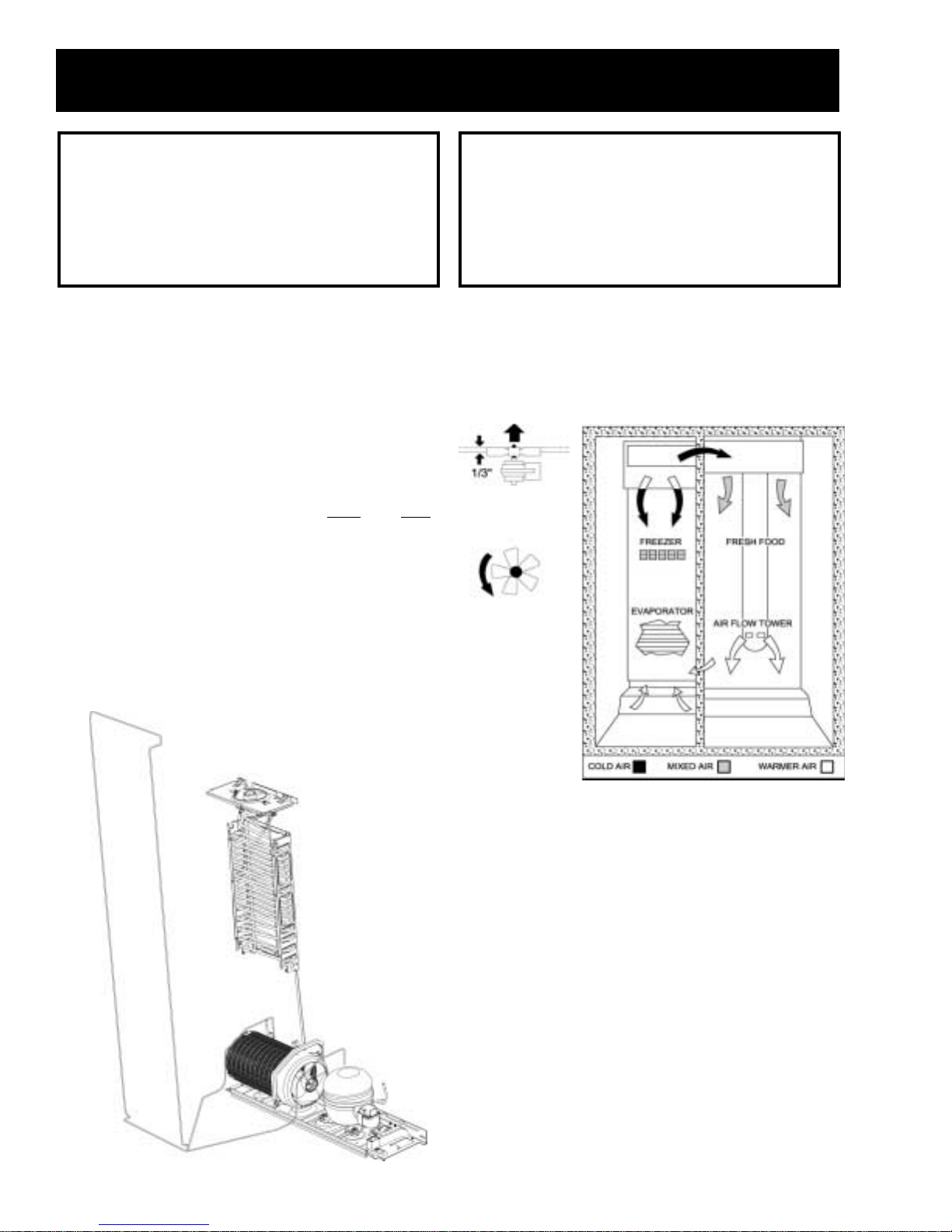
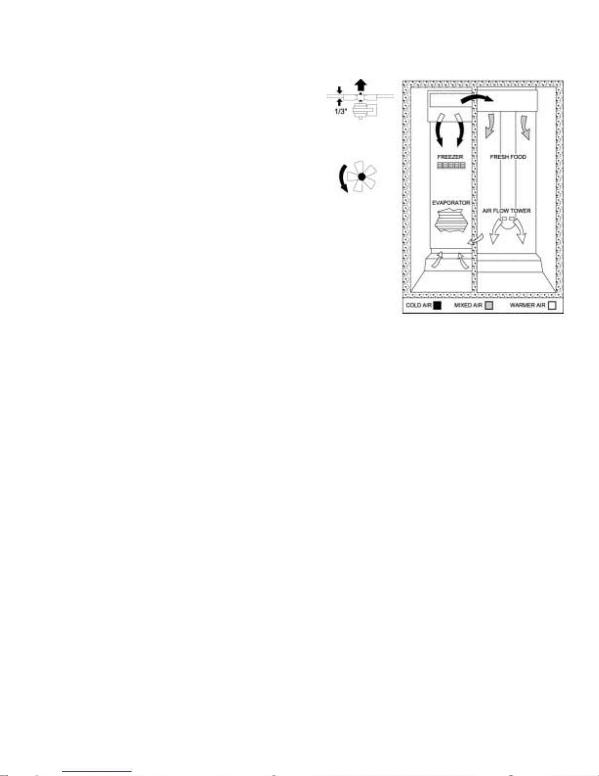
AIR FLOW
The freezer cabinet is designed so that air is
drawn into the bottom of the air tunnel and through
the evaporator when the evaporator fan is
operating. The chilled air is then pushed out into
the top of the freezer.
The fresh food compartment receives chilled air
via an electronic damper that is positioned at the
top rear of the refrigerator between the freezer
cabinet and the fresh food cabinet. The damper is
controlled by the main control board and when
open, allows chilled air from the freezer air tunnel
to move into the fresh food air tower. The fresh
food air tower contains a fresh food fan which
draws chilled air from the freezer (through the
damper) into the air tower. The air tower directs
chilled air across the top of the fresh food cabinet
to two outlets. The air tower also directs chilled air
down the back wall of the fresh food cabinet. The
chilled air exits the air tower through vents in the
tower.
Air returns from the fresh food cabinet to the
freezer cabinet via a mullion located to the left of
the FRESH PRODUCE drawer.
– 11 –
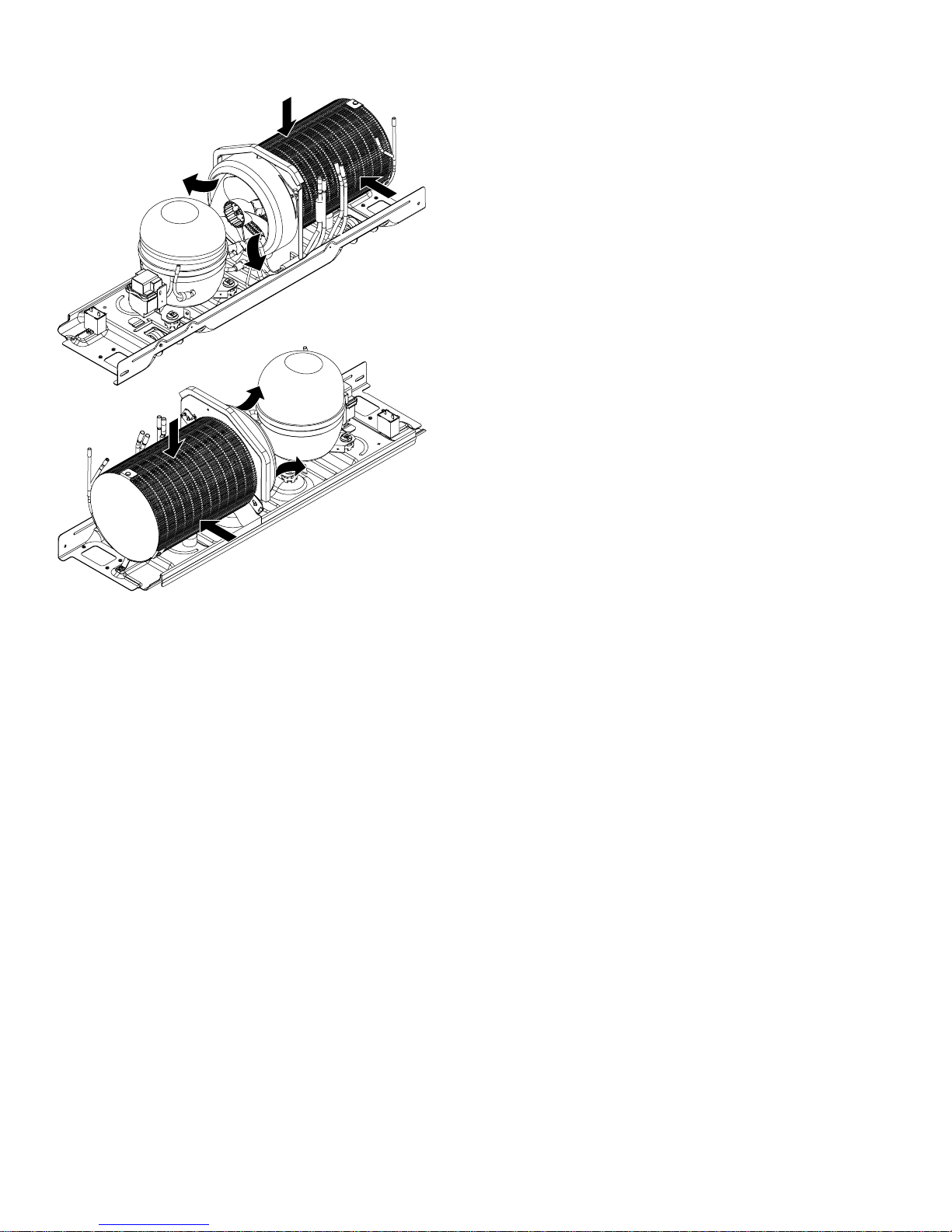
“Jelly Roll” Condenser
GEA00911
The “jelly roll” condenser is a new type of
condenser. The condenser fan is located at one
end of the “jelly roll” condenser and a solid plate is
located at the other end. Air is drawn in through
the outside diameter of the condenser and pulled
out by the condenser fan. The condenser is
located in the machine compartment which can be
accessed from the back of the unit at the bottom.
– 12 –
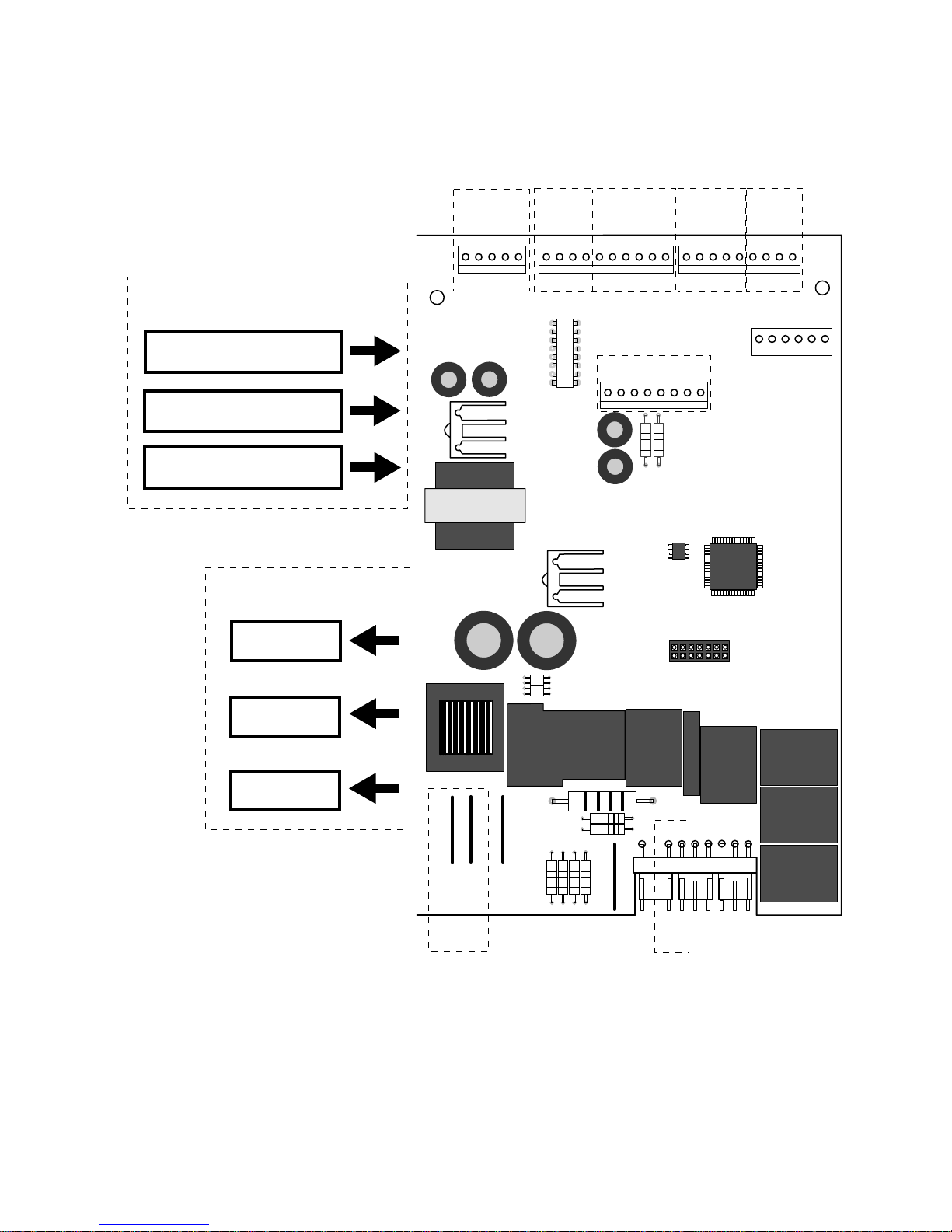
Main Control Board
INPUTS
ACCUMULATED FF AND FRZ
DOOR OPENINGS (MINUTES)
COMPRESSOR RUN TIME
(MINUTES)
DEFROST HEATER ON TIME
(MINUTES)
OUTPUTS
COOLING
2 +12V
1 COMM
3 -COM
4 DI
COMMUNICATION
INPUT/OUTPUT
5 DO
1
DAMPER
COILS
5
1
J4
ENCODER
INPUTS
J3
FAN OUTPUTS
1
THERMISTOR
10
INPUTS
1
8
J1
MODEL
SELECT
1
9
6
J5
J2
PROCESSING
UNIT
1
J6
2
PRE-CHILL
DEFROST
L1
DEFR
COMP
COMPRESSOR
AND
DEFROST
OUTPUTS
LINE
K4
COMP
K3
N
PAN_HTR
DEFROST
DFZ
DOOR
SWITCH
INPUTS
DFF
QC
K5
OCH
J7
K7
COMMON
WATER
PAN/HTR
CRUSHER
AUGER
K6
K2
K1
WATER
C/CR
AUGER
– 13 –
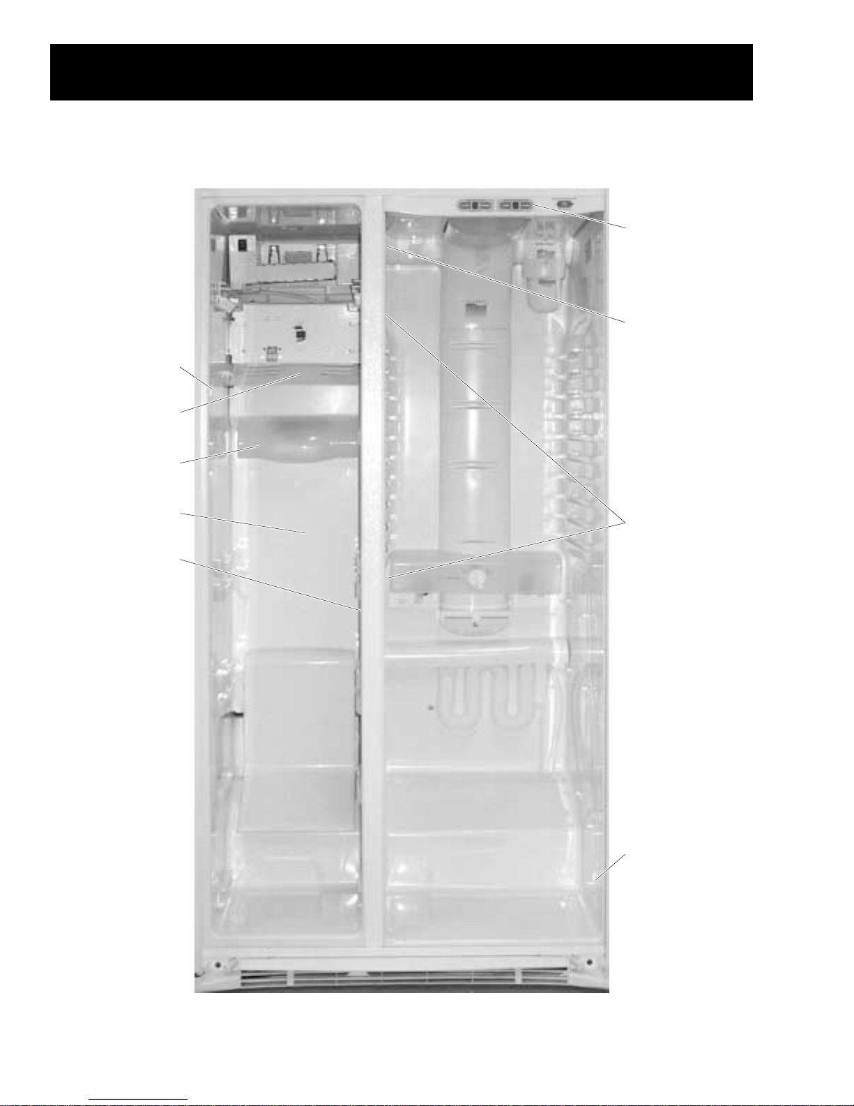
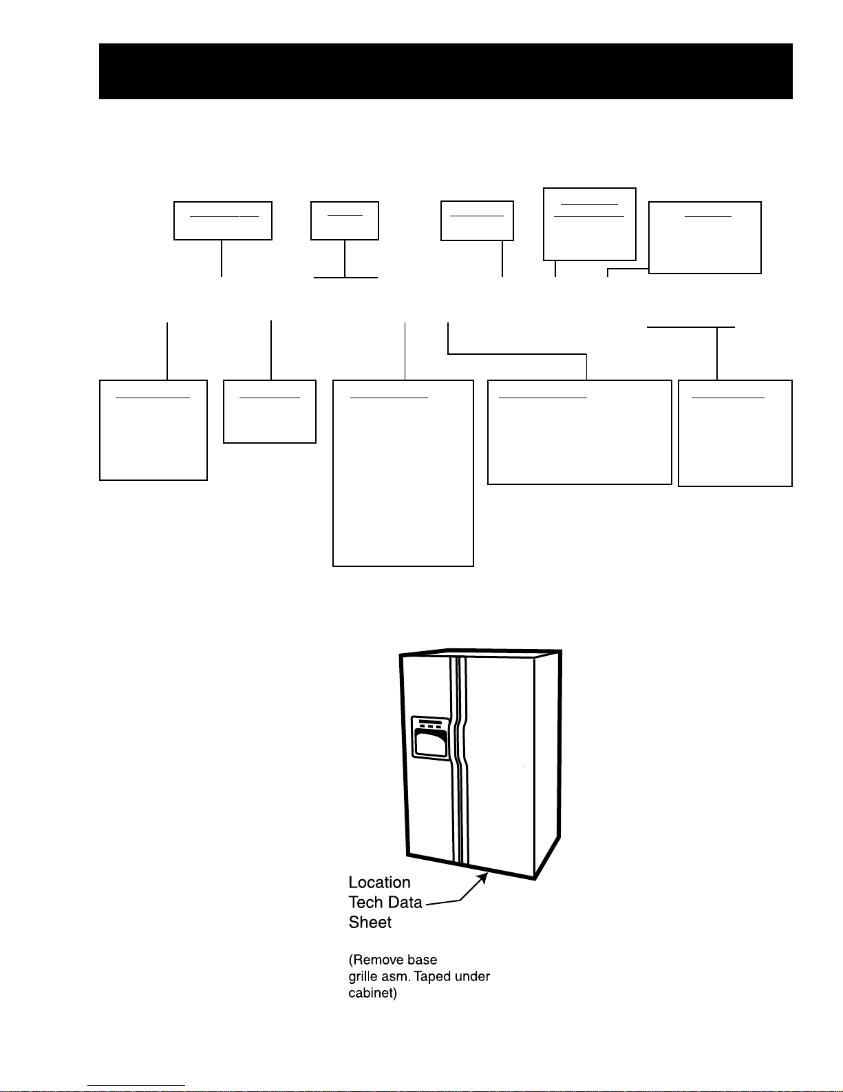
General Locator Views
Temperature
Thermistor
Thermistor
Thermistor
Temperature
Temperature
Controls
Controls
Freezer Light
Freezer Light
Switch
Switch
Evaporator
Evaporator
Fan
Fan
Evaporator
Evaporator
Thermistor
Thermistor
EvaporatorEvaporator
Freezer
Freezer
Thermistor
Thermistor
DamperDamper
Fresh Food
Fresh Food
Thermistor
Thermistor
– 14 –
GEA00979
Fresh Food
Fresh Food
Light Switch
Light Switch
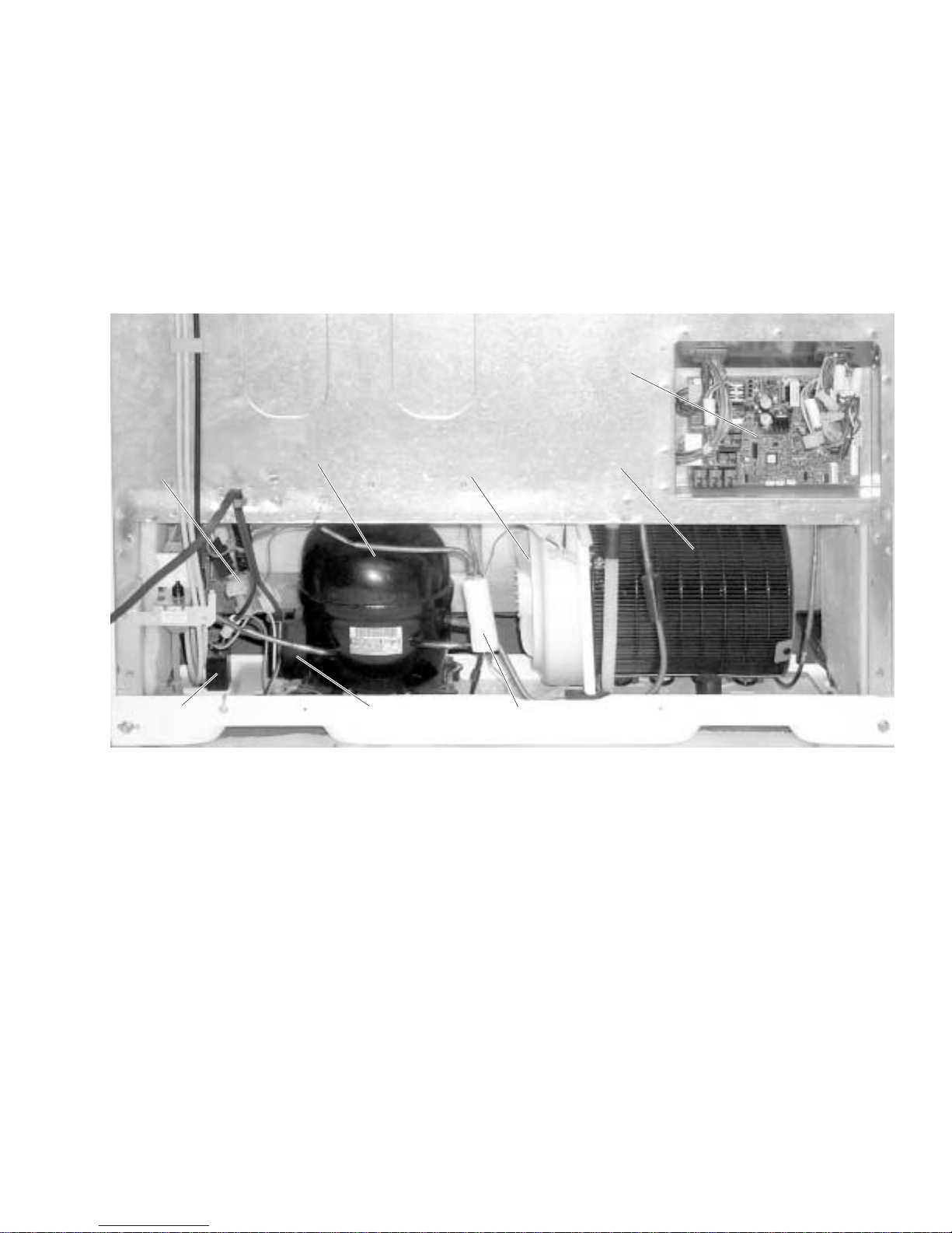
Water
Water
Solenoids
Solenoids
CompressorCompressor
Condenser
Condenser
Fan
Fan
Control
Control
Board
Board
Jelly Roll
Jelly Roll
Condenser
Condenser
Overload and Relay
Overload and Relay
(under cover)
(under cover)
DryerDryerCapacitorCapacitor
GEA00977
– 15 –

Mechanical Disassembly
Table of Contents
Door Handle. . . . . . . . . . . . . . . . . . . . . . . . . . . . . . . . . . . . . . . . . . . . . . . . . . . . . . 18
Door Gasket. . . . . . . . . . . . . . . . . . . . . . . . . . . . . . . . . . . . . . . . . . . . . . . . . . . . . . 18
Fresh Food Compartment Quick Access Door . . . . . . . . . . . . . . . . . . . . . . . . . 18
Fresh Food Door Light Switch
Fresh Food Compartment Door Shelves . . . . . . . . . . . . . . . . . . . . . . . . . . . . . . 19
Fresh Food Compartment Shelves . . . . . . . . . . . . . . . . . . . . . . . . . . . . . . . . . . . 19
Fresh Food Compartment Drawers . . . . . . . . . . . . . . . . . . . . . . . . . . . . . . . . . . . 19
Fresh Food Compartment Lights . . . . . . . . . . . . . . . . . . . . . . . . . . . . . . . . . . . . 19
Water Filter. . . . . . . . . . . . . . . . . . . . . . . . . . . . . . . . . . . . . . . . . . . . . . . . . . . . . . . 20
Fresh Food Fan and Mullion Damper . . . . . . . . . . . . . . . . . . . . . . . . . . . . . . . . . 20
Deli Fresh Damper . . . . . . . . . . . . . . . . . . . . . . . . . . . . . . . . . . . . . . . . . . . . . . . . 21
Fresh Food Thermistors . . . . . . . . . . . . . . . . . . . . . . . . . . . . . . . . . . . . . . . . . . . . 21
Temperature Control Panel . . . . . . . . . . . . . . . . . . . . . . . . . . . . . . . . . . . . . . . . . 22
Freezer Door Bins . . . . . . . . . . . . . . . . . . . . . . . . . . . . . . . . . . . . . . . . . . . . . . . . . 22
. . . . . . . . . . . . . . . . . . . . . . . . . . . . . . . . . . . . . . . 19
Doors and Door Hinges . . . . . . . . . . . . . . . . . . . . . . . . . . . . . . . . . . . . . . . . . . . . 22
Fresh Food Door Adjustment . . . . . . . . . . . . . . . . . . . . . . . . . . . . . . . . . . . . . . . 23
Rollers . . . . . . . . . . . . . . . . . . . . . . . . . . . . . . . . . . . . . . . . . . . . . . . . . . . . . . . . . . 23
Roller Adjustment . . . . . . . . . . . . . . . . . . . . . . . . . . . . . . . . . . . . . . . . . . . . . . . . . 24
Freezer Compartment Shelves and Bins . . . . . . . . . . . . . . . . . . . . . . . . . . . . . . 24
Freezer Door Light Switch . . . . . . . . . . . . . . . . . . . . . . . . . . . . . . . . . . . . . . . . . . 24
Ice Dispenser . . . . . . . . . . . . . . . . . . . . . . . . . . . . . . . . . . . . . . . . . . . . . . . . . . . . . 24
Ice Dispenser Auger Drive and Cube Solenoid . . . . . . . . . . . . . . . . . . . . . . . . . 25
Icemaker . . . . . . . . . . . . . . . . . . . . . . . . . . . . . . . . . . . . . . . . . . . . . . . . . . . . . . . . . 25
– 16 –

Freezer Light . . . . . . . . . . . . . . . . . . . . . . . . . . . . . . . . . . . . . . . . . . . . . . . . . . . . . 26
Evaporator Fan . . . . . . . . . . . . . . . . . . . . . . . . . . . . . . . . . . . . . . . . . . . . . . . . . . . 26
Evaporator Thermistor . . . . . . . . . . . . . . . . . . . . . . . . . . . . . . . . . . . . . . . . . . . . . 27
Defrost Thermostat . . . . . . . . . . . . . . . . . . . . . . . . . . . . . . . . . . . . . . . . . . . . . . . . 27
Defrost Heater . . . . . . . . . . . . . . . . . . . . . . . . . . . . . . . . . . . . . . . . . . . . . . . . . . . . 27
Evaporator Drip Pan . . . . . . . . . . . . . . . . . . . . . . . . . . . . . . . . . . . . . . . . . . . . . . . 28
Evaporator . . . . . . . . . . . . . . . . . . . . . . . . . . . . . . . . . . . . . . . . . . . . . . . . . . . . . . . 28
Freezer Thermistor . . . . . . . . . . . . . . . . . . . . . . . . . . . . . . . . . . . . . . . . . . . . . . . . 28
Condenser Fan . . . . . . . . . . . . . . . . . . . . . . . . . . . . . . . . . . . . . . . . . . . . . . . . . . . 29
Main Processor Card . . . . . . . . . . . . . . . . . . . . . . . . . . . . . . . . . . . . . . . . . . . . . . 29
Water Solenoids . . . . . . . . . . . . . . . . . . . . . . . . . . . . . . . . . . . . . . . . . . . . . . . . . . 29
– 17 –
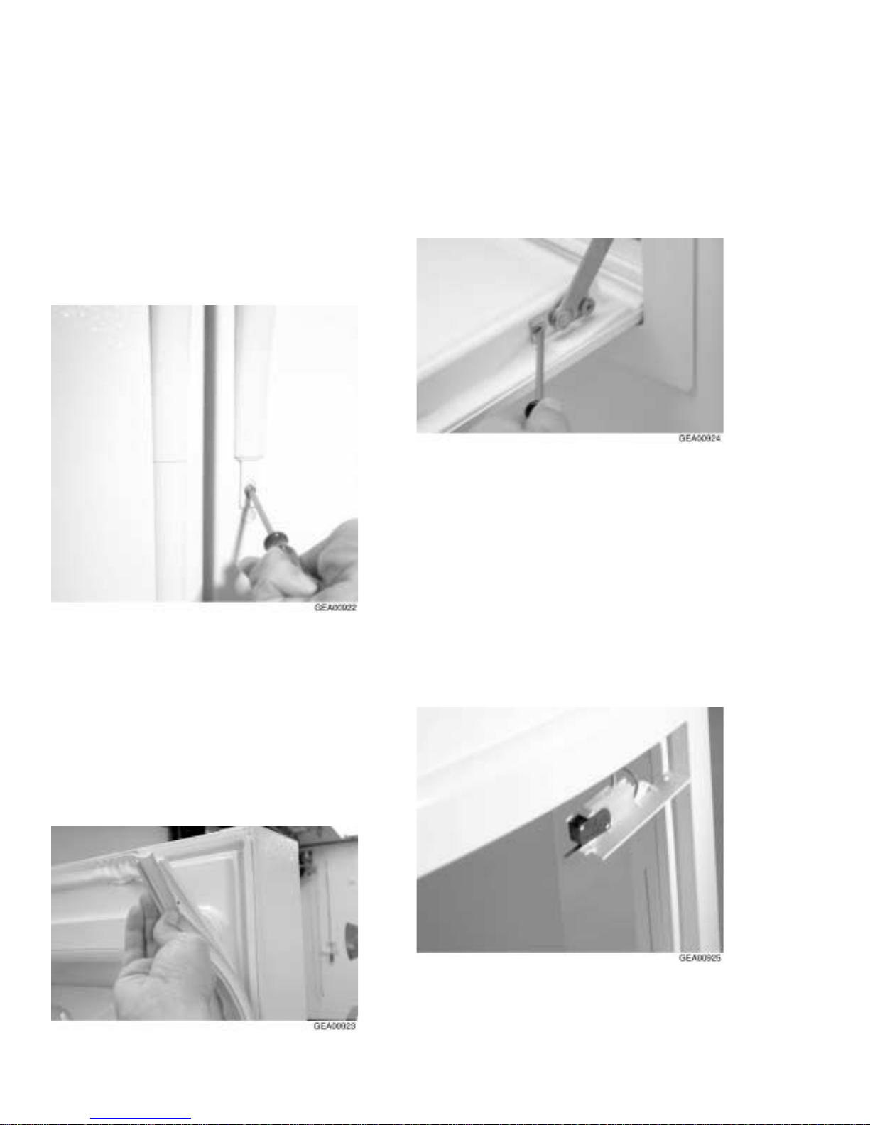
Door Handle
The door handles allow access into the fresh food
and freezer compartments. They are front
mounted with 1 Torx head screw.
1. With a small flat-blade screwdriver, slide the
handle trim down and pull it out.
2. Remove the lower Torx head screw.
3. Lift the handle in and upward motion until it
disengages the locking tabs. Pull the handle
outward to remove it.
Fresh Food Compartment Quick Access
Door
The fresh food compartment allows access to the
fresh food compartment without opening the fresh
food door.
1. Open the quick access door and remove the
hinge Torx head screws (2), located on each
side of the door.
Door Gasket
The door gasket is a molded gasket set into a
channel located in the door liner.
1. Open the door.
2. Grasp the gasket and pull in an outward
motion until the molded gasket separates from
the door liner.
2. With a small flat-blade screwdriver, remove the
door frame and door frame assembly.
3. Remove the gasket and slide the door out of
the frame.
4. The quick access door also has an interlock
switch located at the top right-hand side of the
interior frame. Remove the Phillips screw and
slide the switch assembly down and out.
5. Disconnect the wires to the switch and remove
it.
– 18 –

Fresh Food Door Light Switch
GEA00928
GEA00929
In addition to the quick access door light switch,
the fresh food compartment has a door light switch
located in the lower right corner for the
compartment.
1. Use a small flat-blade screwdriver to unlock
the locking tab tabs and pull the switch out until
the wire connector is visible.
2. Disconnect the connector and remove the
switch.
Fresh Food Compartment Drawers
Fresh food compartment drawers are designed for
storage of fruits, vegetables, and deli items. The
drawers are located in the lower portion of the
fresh food compartment.
1. Pull out the drawer until the rollers meet the
mechanical stop.
Fresh Food Compartment Door Shelves
The door shelves allow storage of perishable
items.
1. Tilt the shelf up and slide it out.
GEA00927
Fresh Food Compartment Shelves
These shelves allow the storage of larger items
and pull out for easy access.
1. Pull the shelf out until the shelf stop tab meets
the compartment stop.
2. Tilt the drawer up and pull it out until it is
removed.
Fresh Food Compartment Lights
The fresh food compartment lights are located in
the upper and lower portion of the fresh food
compartment.
1. To access the upper lights, remove the upper
opaque cover by unlocking the tabs and
pulling the cover down.
2. Push the shelf stop tab down and pull the
shelf out until it is removed.
– 19 –

GEA00930
2. To access the lower lights, pull the deli fresh
damper adjusting knob off.
3. Lift the opaque cover off the tabs.
GEA00931
Water Filter
The water filter is located in the upper right-hand
portion of the fresh food compartment. The water
filter, filters water for the ice maker and the water
dispenser. An LED on the temperature control
panel will illuminate when the filter needs to be
changed.
Fresh Food Fan and Mullion Damper
The fresh food compartment fan is located under
the upper ductwork in the fresh food compartment.
This fan distributes cold air from the freezer via the
mullion damper. The mullion damper is located in
the same assembly as the fan. Both are controlled
by the processor.
1. Remove the deli fresh adjusting knob and light
cover.
2. Unlock the upper and lower locking tabs for the
center ductwork and remove. The ductwork is
also fastened with double-sided tape at the
upper and lower portions.
1. Turn the water filter 1/2 turn counterclockwise
and pull it down.
2. To install the filter, push it up while turning 1/2
turn clockwise. Do not force the filter.
– 20 –
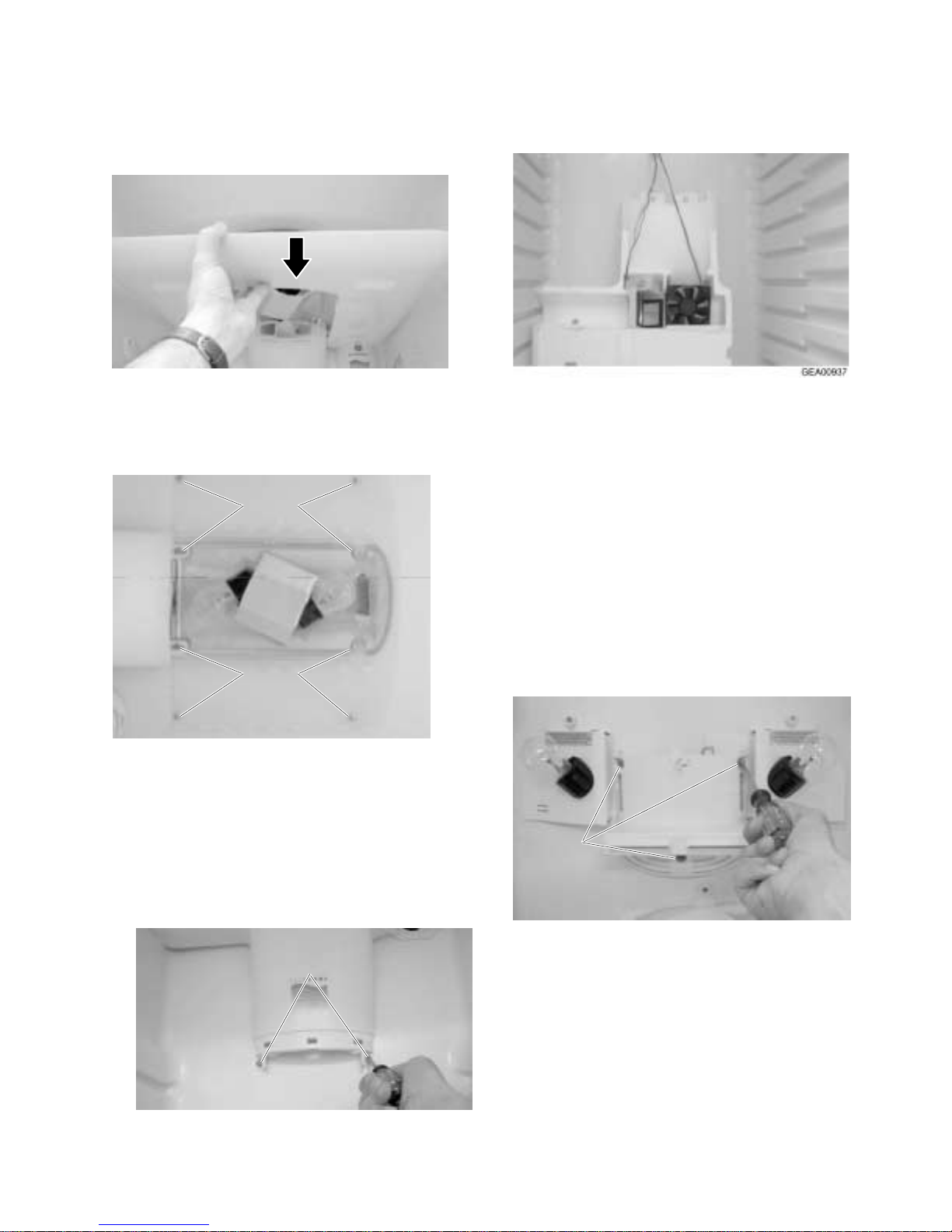
3. Remove the upper water filter cover.
Screws
4. Unlock the upper opaque light cover tabs and
remove the cover.
5. Unlock the upper ductwork tabs and remove it.
GEA00934
9. Lay the fan and damper assembly against the
compartment and open the back cover.
10. Disconnect the wire connections and remove
the damper or fan.
6. Remove the Phillips head screws (8) for the
upper light assembly plastic bracket.
ScrewsScrews
ScrewsScrews
GEA00935
7. Pull the stainless steel light bracket down until
the wires are exposed and disconnect them.
8. Remove the Phillips head screws (2) for the
fresh food fan and damper cover and remove
the cover.
Deli Fresh Damper
The deli fresh damper is located at the bottom of
the cold air ductwork. It allows the flow of cold air
to be adjusted to the deli fresh drawer.
1. Remove the deli fresh damper adjusting knob
and the lower light cover.
2. Remove the center ductwork by unlocking
upper and lower tabs. Double-sided tape is
applied to upper and lower areas.
3. Remove the damper Phillips head mounting
screws (3) and remove the damper.
Screws
Screws
ScrewsScrews
GEA00938
Fresh Food Thermistors
The fresh food thermistors are located at the
upper and lower portions of the fresh food
compartment. They send temperature signals to
the processor.
GEA00936
– 21 –
 Loading...