

Page 1

Installation
Instructions
Advantium® 120V Built-In
SpeedCook
& Convection 120V Built-In
Ovens
PSB9100DF
PSB9100SF
PWB7027EL
PWB7027SL
49-40775
MFL59060921
10-16 GEA
Español
For a Spanish version of this manual, visit
our Website at GEAppliances.com.
Para consultar una version en español de
este manual de instrucciones, visite nuestro
sitio de internet GEAppliances.com.
GE is a trademark of the General Electric Company. Manufactured under trademark license.
Page 2
Safety Information
BEFORE YOU BEGIN
Read these instructions completely and
carefully.
IMPORTANT — Save these
instructions for local inspector’s use.
IMPORTANT — Observe all governing
codes and ordinances.
• Note to Installer — Be sure to leave these
instructions with the Consumer.
• Note to Consumer — Keep these
instructions with your Owner’s Manual for
future reference.
• Skill Level — Installation of this appliance
requires basic mechanical and electrical skills.
• Completion Time — 1 Hour.
• Proper installation is the responsibility of the
installer.
• Product failure due to improper installation is
not covered under the warranty. See Owner’s
Manual for warranty information.
IMPORTANT — Use this oven only
for its intended purpose. Never use the oven
for warming or heating a room. Prolonged use
of the oven without proper ventilation can be
hazardous.
CAUTION
For personal safety, remove house fuse or
oven circuit breaker before beginning
installation to avoid severe or fatal shock injury.
CONTENTS
Design Information
Models Available .............................................. 2
Product Dimensions and Clearances ............... 4
Tools Required ................................................ 4
Parts Supplied ................................................. 4
Advance Planning ........................................... 4
Installation Preparation
Electrical Requirements ...................................4
Prepare the Opening .....................................5,6
Remove the Packaging .................................... 6
Installation Instructions
Step 1, Slide the Oven into the Cutout ............ 7
Step 2, Install Bottom Trim ................................7
Step 3, Install Mounting Screws ....................... 7
Step 4, Finalize Installation .............................. 7
MODELS AVAILABLE
Profile Models:
PSB9100DFWW – White
PSB9100DFBB – Black
PSB9100SFSS – Stainless Steel
PWB7027EL – Slate*
PWB7027SL – Stainless Steel*
* Convection model
CAUTION
For personal safety, the mounting surface must
be capable of supporting the cabinet load, in
addition to the added weight of the 80-pound
oven and 30-pound drawer, plus additional
oven loads of up to 50 pounds or a total weight
of up to 160 pounds.
CAUTION
For personal safety this product cannot be
installed in cabinet arrangements such as an
island, a peninsula or below a countertop.
2
Page 3
Design Information
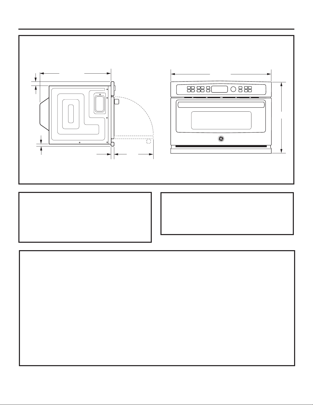
PRODUCT DIMENSIONS AND CLEARANCES
1-3/10”
1”
21-1/2”
TOOLS REQUIRED
• #2, Phillips screwdriver
• Handheld drill
• High-speed drill bit, 1/8” diameter
• 3/8”, slot-head screwdriver
26-3/4”
18-5/8”
13”
1-4/5”
NOTE: Appearance may vary slightly by model.
PARTS SUPPLIED
• 6 Brass screws (3 required, 3 extra)
• 5 Color-matched screws (4 required, 1 extra)
• Bottom trim
ADVANCE PLANNING
• These ovens may be installed directly into a 27”wide oven cabinet.
• The front surface of the oven will be nearly flush
with surrounding cabinetry doors.
• This oven can be installed over any GE
Appliances single electric built-in oven or a
warming drawer or both.
IMPORTANT: This oven is not approved for use
above another built-in SpeedCook oven, a side-byside installation or below a countertop.
• For personal safety, this oven cannot be installed
in a cabinet arrangement such as an island or
peninsula.
• The oven must be installed at least 36-3/4” above
the floor.
• Allow for clearance to adjacent corners, walls,
drawers, etc.
• Cabinets installed adjacent to wall ovens
must have an adhesion spec of at least 194ºF
temperature rating.
The oven must be securely installed in a cabinet
that is firmly attached to the house structure.
Weight on the oven door could cause the oven to
tip and result in injury. Never allow anyone to climb,
sit, stand or hang on the oven door.
3
Page 4
Installation Preparation
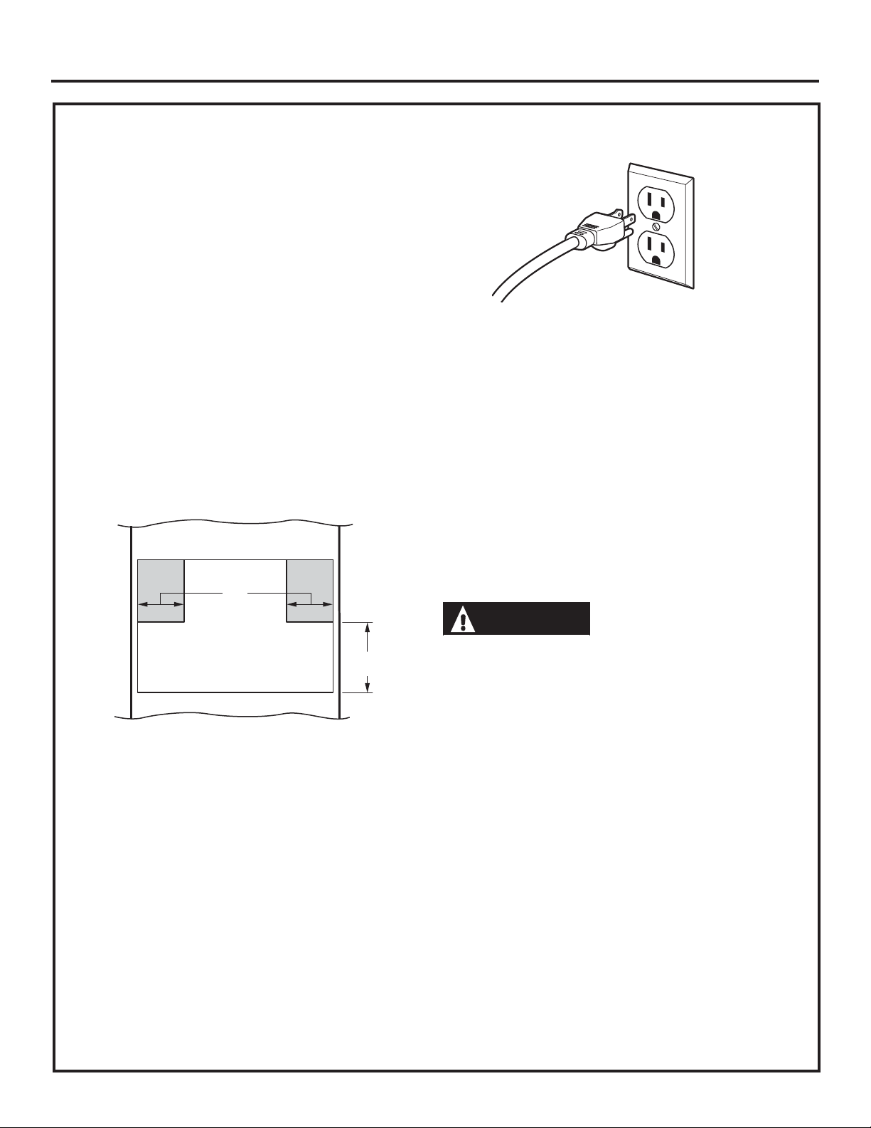
ELECTRICAL REQUIREMENTS
Single Advantium/Convection 120
Installation:
This product requires a 120-volt, 60 Hz, 15-amp
circuit and draws 1.8 kilowatts. This product must
be connected to a supply circuit of the proper
voltage and frequency.
• Wire size must conform to the requirements of
the National Electrical Code or the prevailing local
code for this kilowatt rating.
• The power supply cord and plug should be
brought to a separate 15- or 20-ampere branch
circuit single grounded receptacle. The outlet box
should be located within reach of the 48” power
cord.
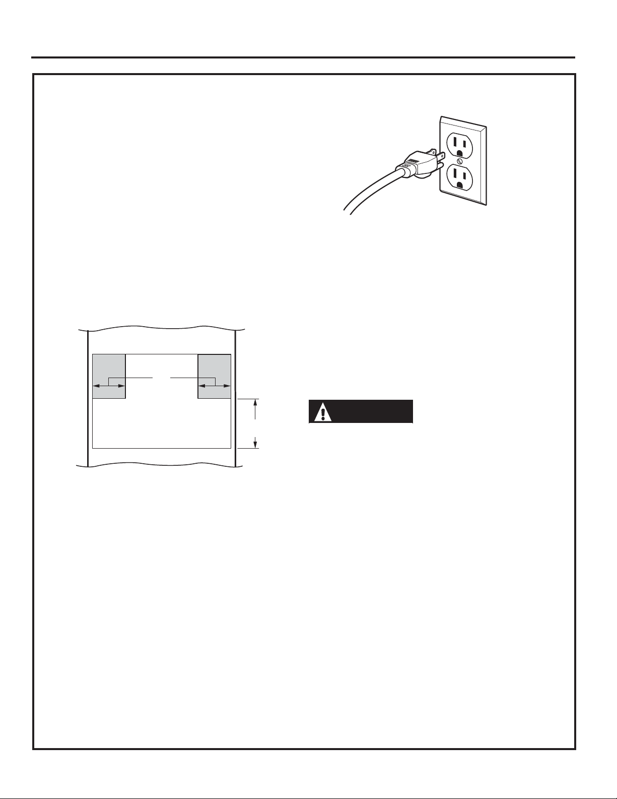
ELECTRICAL LOCATION
6”
GROUNDING
INSTRUCTIONS
This appliance must be grounded. In the event of
an electrical short circuit, grounding reduces the
risk of electric shock by providing an escape wire
for electric current. This appliance is equipped
with a cord having a grounding wire with a
grounding plug. The plug must be plugged into
an outlet that is properly installed and grounded.
9”
Locate outlet box in the shaded area
Install a recessed electrical outlet in the back
wall of the opening within 6” of either side and
at least 9” above the cutout floor.
WARNING
Improper use of the
grounding plug can result in a risk of
electric shock.
Important: (Please read carefully).
The power cord of this appliance is equipped with
a three-prong (grounding) plug that mates with a
standard three-prong grounding wall receptacle
to minimize the possibility of electric shock.
Consult a qualified electrician or serviceman if
the grounding instructions are not completely
understood, or if doubt exists as to whether the
appliance is properly grounded.
• Where a standard two-prong wall receptacle is
encountered, it is the personal responsibility and
obligation of the consumer to have it replaced with
a properly grounded three-prong wall receptacle.
Do not, under any circumstances, cut or remove
the third (ground) prong from the power cord.
DO NOT USE AN EXTENSION CORD. If the
power supply cord is too short, have a qualified
electrician or serviceman install an outlet near the
appliance.
4
Page 5
Installation Preparation
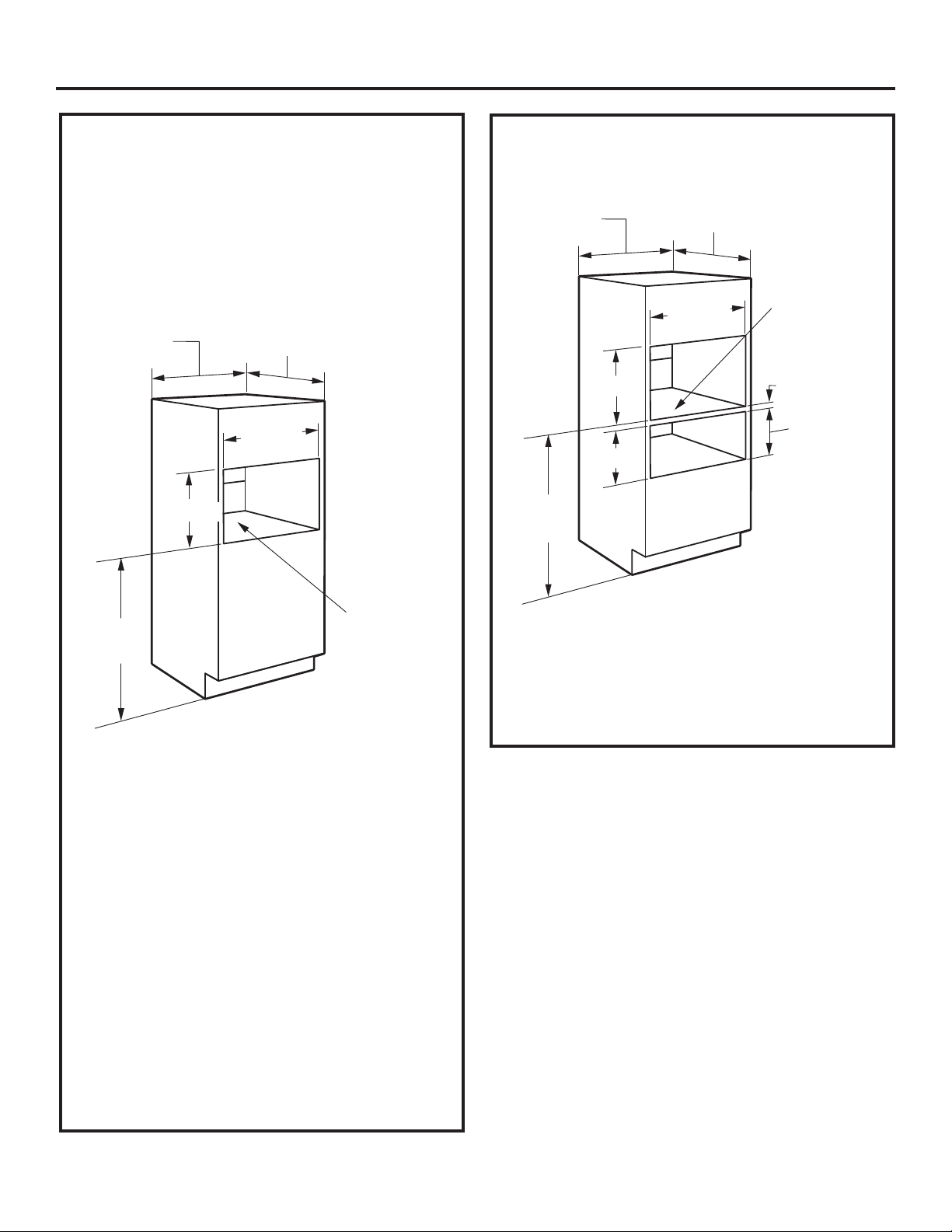
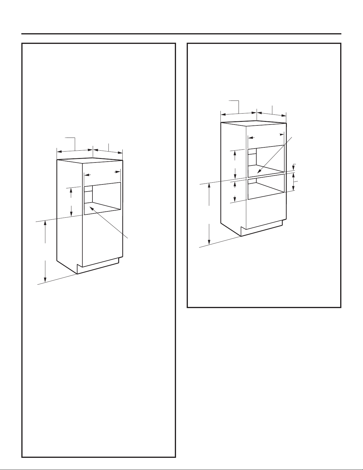
PREPARE THE OPENING
The Advantium/Convection 120 can be installed
in combination with other GE appliances. Always
follow each product’s Installation Instructions to
complete the installation.
Single Advantium/Convection 120
Installation:
Order a 27”-wide single oven cabinet or cut the
opening in a wall to the dimensions shown.
27”
17-1/2”
36-3/4”
Min.
• Always maintain 36-3/4” minimum height from
the floor to the cutout in any single or combined
installation.
• Allow 1-1/4” case trim overlap at the top and
7/8” overlap on the bottom and each side of the
opening.
• Oven overlaps will conceal cut edges on all
sides of the opening.
23-1/2”
25-1/8”
Construct
Base
Min. 3/8”
Plywood
Supported
by 2 x 4
or 1 x 2
Runners all
Four Sides
PREPARE THE OPENING (CONT.)
Installation over a GE Appliances Warming
Drawer:
27”
17-1/2”
9-1/4”
36-3/4”
Min.
NOTE: Additional clearances between the cutouts
may be required. Check to be sure the oven
supports above the Warming Drawer location do
not obstruct the required interior depth and height.
See Warming Drawer installation instructions for
details.
23-1/2”
25-1/8”
Construct
Solid Bottom
Min. 3/8”
Plywood
Supported
by 2 x 4 or
1 x 2
Runners
all Four Sides
2” Min.
Install 2 x 4 or
2 x 2
Runners or
Solid Bottom.
Must Support
100 lbs.
When installed over a single oven or a warming
drawer, allow at least 2” between the two
openings. This separation will provide clearance
for bottom overlap of the Advantium/Convection
120 and the other appliance overlaps.
Construct a solid oven floor of 3/8” min. thick
plywood supported by 2 x 4 runners on all sides.
• The support must be level and rigidly mounted,
flush with the bottom edge of the cutout.
5
Page 6
Installation Preparation
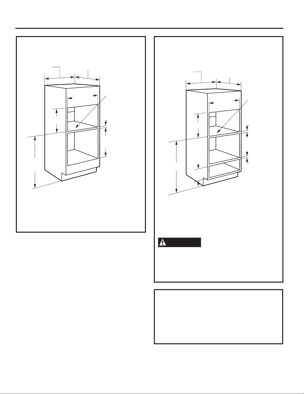
PREPARE THE OPENING (CONT.)
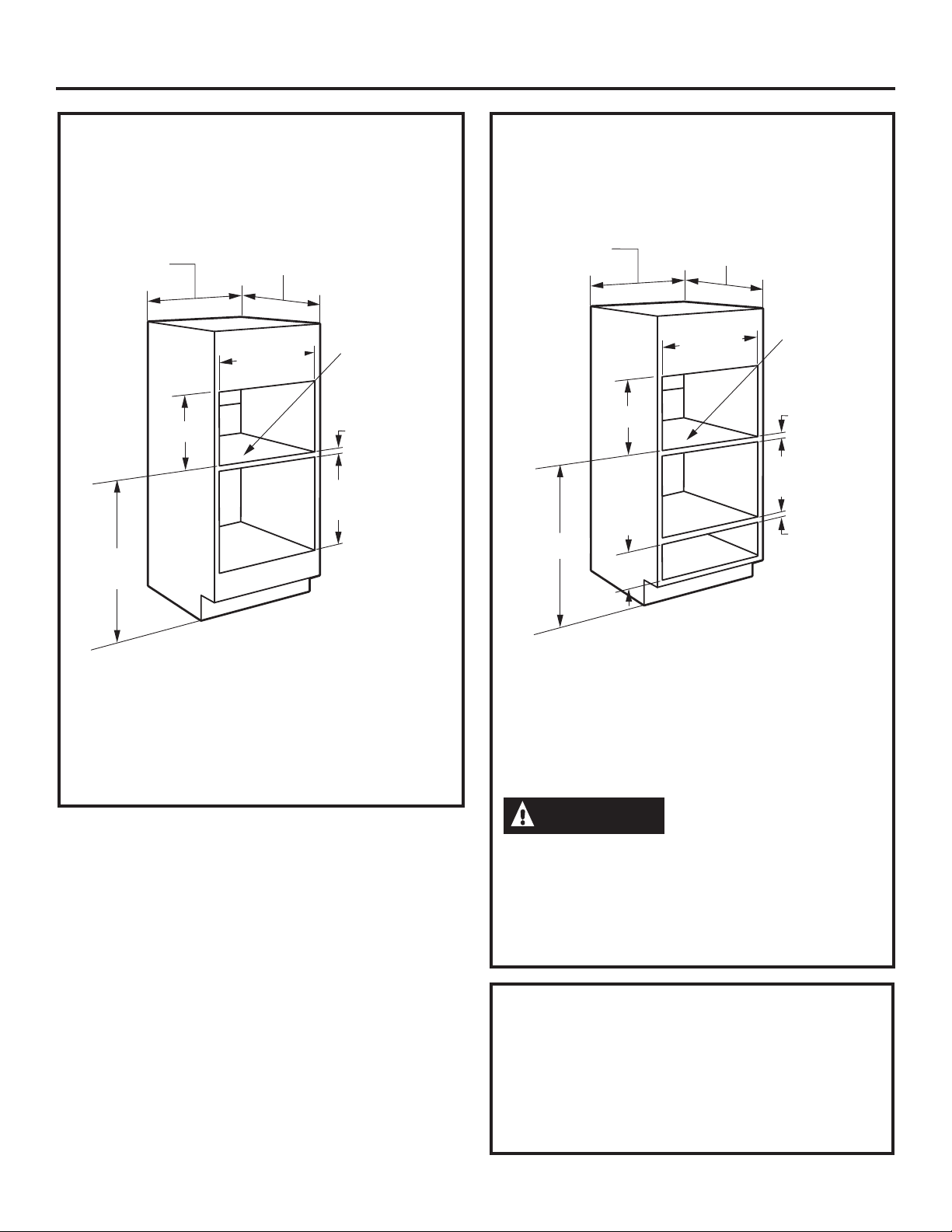
Installation over a GE Appliances Oven:
45-1/4”
Min.
27”
17-1/2”
23-1/2”
25-1/8”
Construct
Solid Bottom
Min. 3/8”
Plywood
Supported by
2 x 4 or 1 x 2
Runners all
Four Sides
2” Min.
Per Oven
Requirement
PREPARE THE OPENING (CONT.)
Installation over a GE Appliances Oven
and Warming Drawer:
Construct
Solid Bottom
Min. 3/8”
Plywood
Supported
by
2 x 4 or 1 x 2
Runners all
Four Sides
2” Min.
Per Oven
Requirement
2” Min.
45-1/4”
27”
17-1/2”
23-1/2”
25-1/8”
9-1/4”
* If you are replacing a GE Appliances electric
double oven with the combined installation of
an Advantium/Convection 120 and a single
oven, use the dimensions shown. The middle
rail separating the two openings may need to
be larger than the 2” minimum shown.
NOTE: Additional clearances between the
cutouts may be required. Check to be sure
the oven supports above the Warming Drawer
location do not obstruct the required interior
depth and height. See Warming Drawer
installation instructions for details.
CAUTION
mounting surface must be capable of supporting
the cabinet load, in addition to the added weight
of the 75-pound product, plus additional oven
loads of up to 50 pounds or a total weight of 125
pounds.
For personal safety, the
REMOVE THE PACKAGING
• Lift the oven out of the carton.
• Remove all packing material and tape.
• Open the door and remove parts box.
• Locate parts package containing mounting
screws.
6
Page 7
Installation
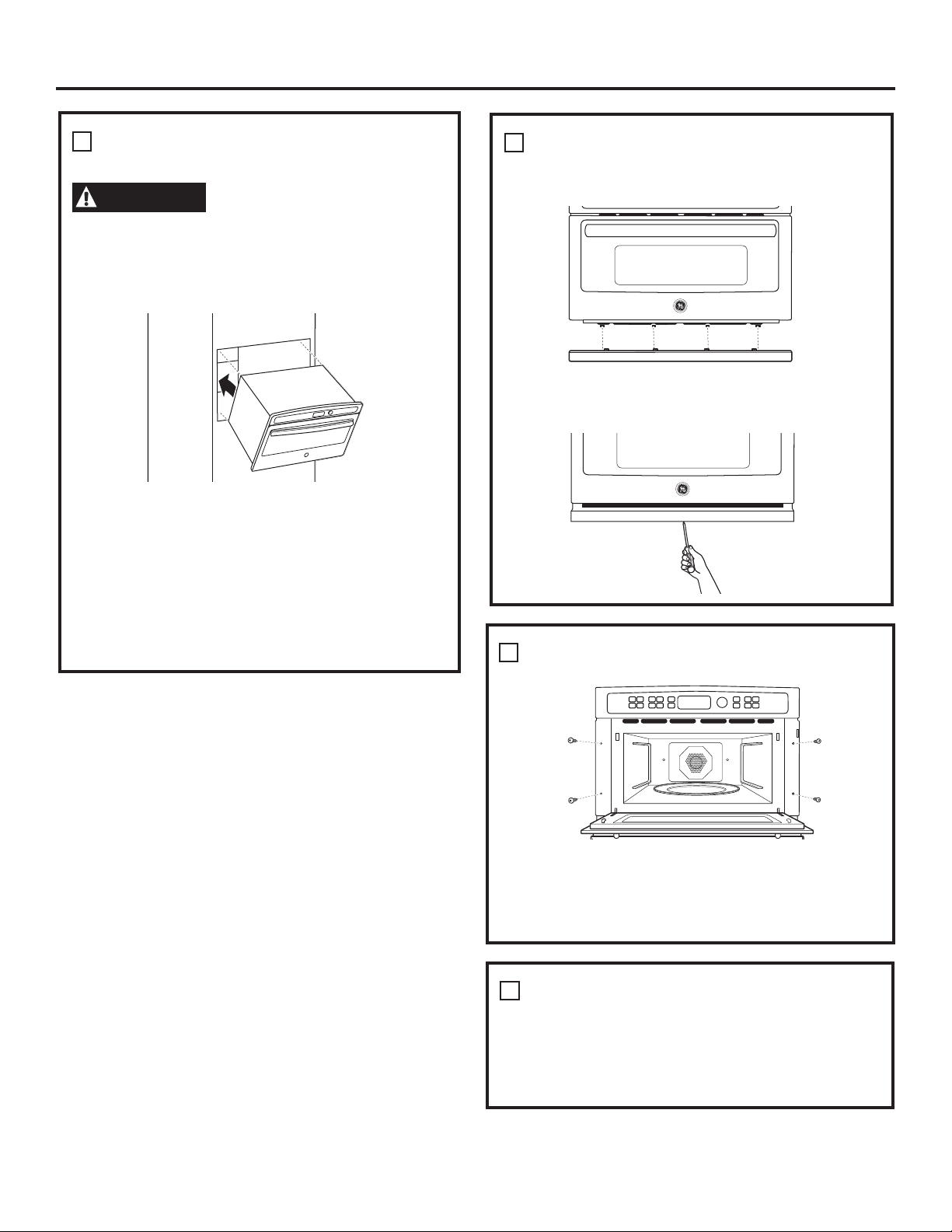
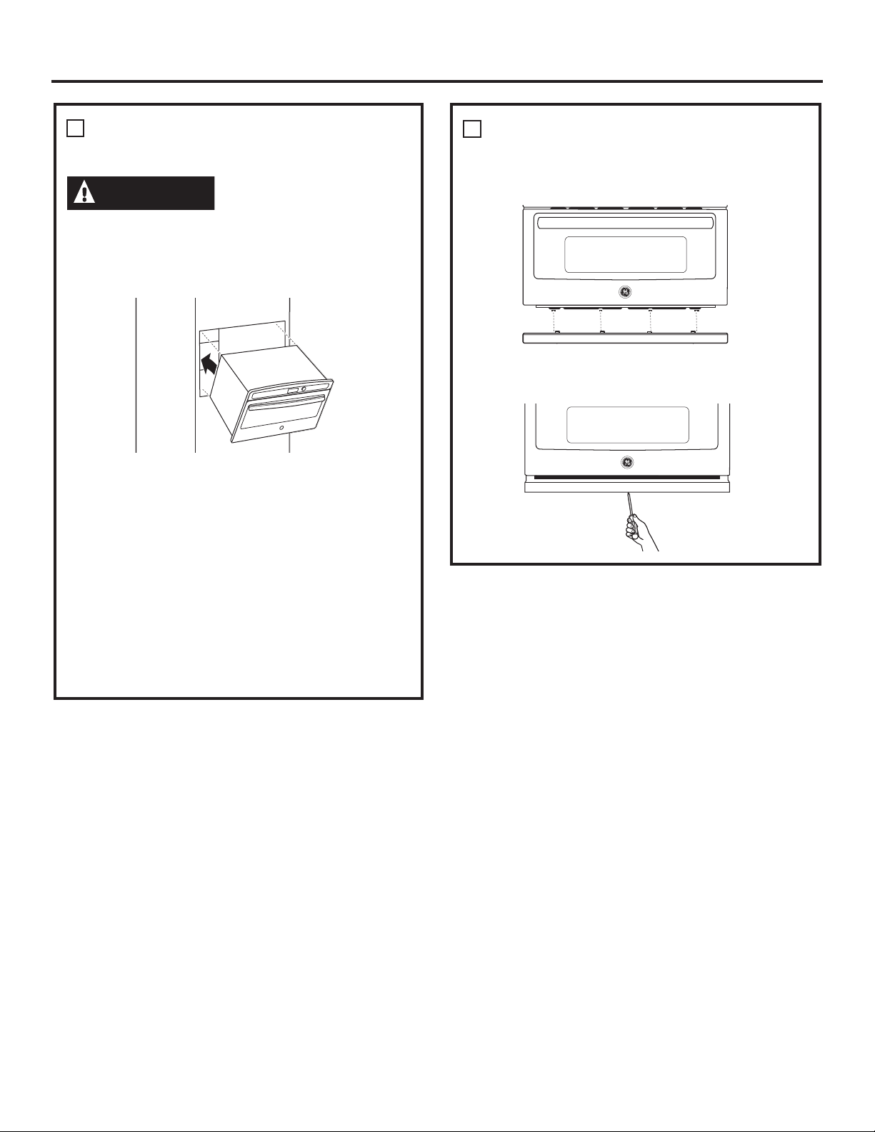
SLIDE THE OVEN INTO THE
1
CUTOUT
CAUTION
to lift the oven into the opening. Grasp the bottom
at the front and rear. DO NOT USE THE
HANDLE TO LIFT THE OVEN. DAMAGE WILL
OCCUR!
• Lift and hold the oven at the front of the
opening. Hold the oven at a 45º angle and plug
in the power cord.
• Carefully, slide the oven into the cabinet part
way. Leave the oven a few inches forward of
the cabinet frame.
Two people are required
INSTALL BOTTOM TRIM
2
• Align bottom trim tabs to slots in the bottom
of the oven.
• Secure the bottom trim to the bottom of the oven
using 3 brass screws provided.
• Check to be sure the power cord is not trapped
under the oven or along the sides of the oven.
INSTALL MOUNTING SCREWS
3
• Drill pilot holes through the side flanges, 2 on
each side.
• Drive the color-matched screws into the side
flange.
FINALIZE INSTALLATION
4
• Turn the power on at the source. The interior
light should come on when the door is opened.
• Refer to the Owner
instructions.
’
s Manual for operating
7
Page 8

Notes
8
Printed in Korea
Page 9

Instrucciones
de
instalación
Hornos de cocción rápida
empotrados de 120V
®/
Advantium
PSB9100DF
PSB9100SF
PWB7027EL
PWB7027SL
Convección
49-40775
MFL59060921
10-16 GEA
GE is a trademark of the General Electric Company. Manufactured under trademark license.
Page 10
Información de seguridad
ANTES DE COMENZAR
Lea estas instrucciones por completo y con
detenimiento.
IMPORTANTE — Guarde estas
instrucciones para el uso de inspectores locales.
IMPORTANTE — Cumpla con todos los
códigos y ordenanzas vigentes.
• Nota al instalador — Asegúrese de dejar estas
instrucciones con el Consumidor.
• Nota al consumidor — Mantenga estas
instrucciones con el Manual del Propietario para
referencia futura.
• Nivel de capacidad — La instalación de
este aparato requiere capacidades mecánicas y
eléctricas básicas.
• Tiempo de finalización — 1 hora.
• La instalación adecuada es responsabilidad
del instalador.
• La garantía no cubre fallas producidas
por la instalación inadecuada del producto.
Consulte el Manual del propietario para
obtener información sobre la garantía.
CONTENIDOS
Información sobre el diseño
Modelos disponibles ...................................... 2
Dimensiones del producto y espacio libre .... 3
Herramientas necesarias .............................. 3
Partes incluidas ............................................. 3
Planificación anticipada ................................. 3
Preparación para la instalación
Requisitos eléctricos ..................................... 4
Prepare la abertura ................................... 5, 6
Retire el embalaje ......................................... 6
Instalación
Paso 1, deslice el horno dentro del corte .... 7
Paso 2, instale el recorte inferior .................. 7
Paso 3, instale los tornillos de montaje ......... 8
Paso 4, finalice la instalación ........................ 8
MODELOS DISPONIBLES
IMPORTANTE — Utilice este horno
sólo con el objetivo para el que fue creado.
Nunca use el horno para entibiar o calentar una
habitación. El uso prolongado del horno sin una
ventilación adecuada puede resultar peligroso.
PRECAUCIÓN
Para seguridad personal, quite el fusible o el
interruptor de circuitos de la vivienda antes
de comenzar la instalación a fin de evitar una
lesión grave o fatal.
PRECAUCIÓN
Para seguridad personal, la superficie de
montaje debe poder soportar la carga del
gabinete, además de las 80 libras del horno
y las 30 libras del cajón, más las cargas
adicionales del horno de hasta 50 libras o un
peso total de hasta 160 libras.
PRECAUCIÓN
Para su seguridad personal, este producto no
puede ser instalado en arreglos de alacena,
como por ejemplo, islas, penínsulas o debajo de
superficies de trabajo.
Modelos Profile:
PSB9100DFWW– Blanco
PSB9100DFBB – Negro
PSB9100SFSS– Acero inoxidable
PWB7
PWB7027SL – Acero inoxidable*
* Convection model
027EL – Pizzarra*
2
Page 11
Información sobre el diseño
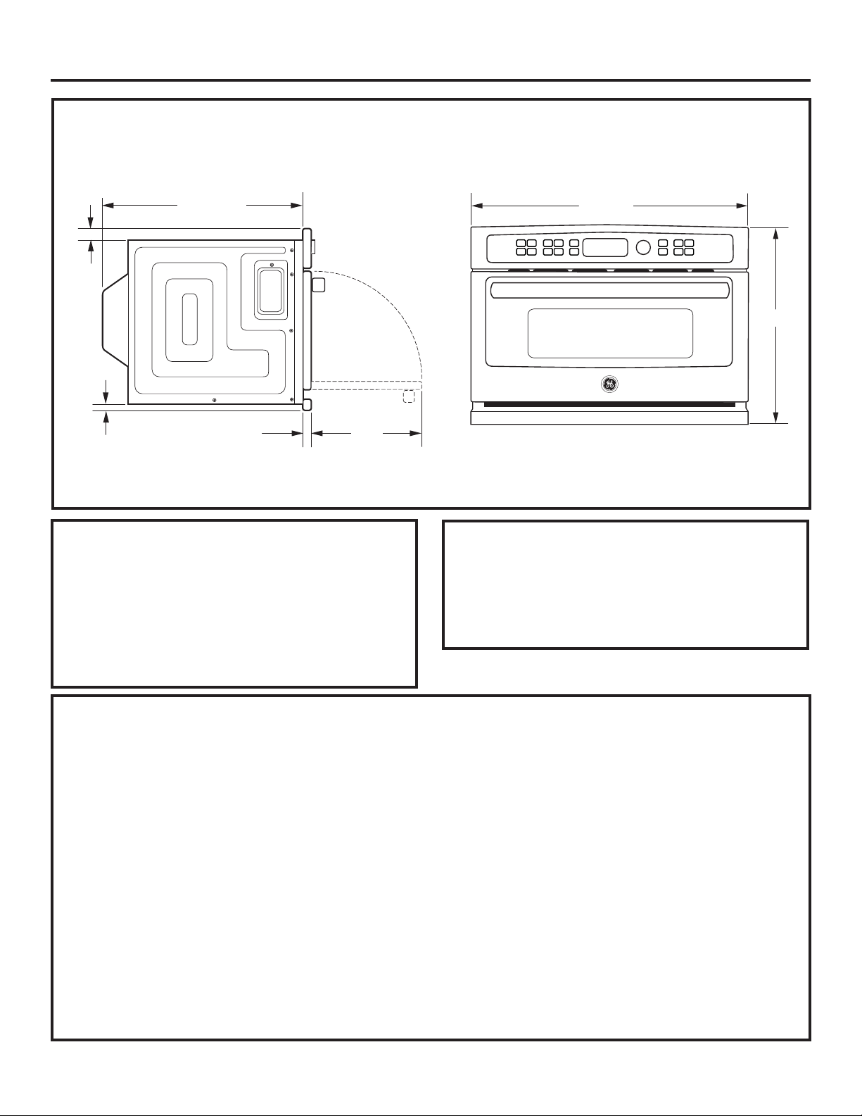
DIMENSIONES DEL PRODUCTO Y ESPACIO LIBRE
1-3/10”
21-1/2”
13”
1”
1-4/5”
HERRAMIENTAS NECESARIAS
• Destornillador Phillips N.°2
• Taladro manual
• Broca para taladro de alta velocidad de 1/8”
de diámetro
• Destornillador para tornillos de cabeza ranurada
de 3/8”
26-3/4”
18-5/8”
NOTA: La apariencia puede variar levemente
de modelo a modelo.
PARTES INCLUIDAS
• 6 tornillos de latón (3 necesarios, 3 adicionales)
• 5 tornillos de color combinado (4 necesarios,
1 adicional)
• Recorte inferior
PLANIFICACIÓN ANTICIPADA
• Estos hornos pueden instalarse directamente
en alacenas para horno de 27” de ancho.
• La superficie delantera del horno quedará casi
al mismo nivel que las puertas de las alacenas
circundantes.
• Este horno puede instalarse sobre cualquier
horno empotrado individual GE Appliances o
sobre un cajón calentador, o ambos.
IMPORTANTE: Este horno no está aprobado
para usarlo sobre otro horno SpeedCook
empotrado, una instalación pegada a otra o debajo
de una superficie de trabajo.
• Para su seguridad personal, este horno no puede
ser instalado en arreglos de alacenas, como por
ejemplo, una isla o una península.
• El horno debe instalarse por lo menos a 36-3/4”
del piso.
• Deje espacio libre para esquinas, paredes,
cajones adyacentes, etc.
• Las alacenas instaladas al lado de hornos
de pared deben tener una especificación de
adhesión de potencia de temperatura de por lo
menos 194°F.
El horno debe instalarse en forma segura en una
alacena sujeta firmemente a la estructura de la
casa. Si coloca peso sobre la puerta del horno,
éste podría volcarse y provocar lesiones. Nunca
permita que nadie se trepe, se siente o se cuelgue
de la puerta del horno, ni que se pare sobre ella.
3
Page 12
Preparación para la instalación
REQUISITOS ELÉCTRICOS
Instalación única del Advantium/
Convección 120:
Este producto requiere un circuito de 120 voltios,
60 Hz, 15 amp y toma 1.8 kilovatios. Este producto
debe conectarse a un circuito de alimentación del
voltaje y la frecuencia adecuados.
• El tamaño del cable debe respetar los requisitos
del Código Eléctrico Nacional (National Electrical
Code)
o el código local en vigencia para esta potencia
de kilowatios.
• El cable y el enchufe de suministro de energía
deben llevarse hacia un receptáculo individual
conectado
a tierra, en un circuito derivado de 15 ó 20
amperios. La caja de distribución debe estar
ubicada al alcance del cable de alimentación de
48”.
UBICACIÓN ELÉCTRICA
6”
INSTRUCCIONES DE
CONEXIÓN A TIERRA
Este electrodoméstico deberá estar conectado a
tierra. En caso de que se produzca un cortocircuito,
la conexión a tierra reduce el riesgo de descarga
eléctrica, brindando un cable de escape de la corriente
eléctrica. Este electrodoméstico está equipado con un
cable de corriente que posee un cable de conexión a
tierra con un enchufe a tierra. El enchufe se deberá
enchufar en un tomacorriente instalado y conectado a
tierra de forma adecuada.
9”
Coloque la caja del tomacorriente
en el área sombreada
Instale un tomacorriente eléctrico empotrado
en la pared posterior de la abertura a 6” de
cada lado y por lo menos a 9” sobre el piso del
corte.
ADVERTENCIA
El uso inadecuado del
enchufe de conexión a tierra puede provocar
un riesgo de descarga eléctrica.
Importante: (Se solicita leer
detenidamente).
electrodoméstico cuenta con un enchufe de 3
clavijas (con cable a tierra) que se conecta a un
tomacorriente de pared estándar de 3 clavijas
para minimizar la posibilidad de descargas
eléctricas. Consulte a un electricista calificado o al
personal del servicio técnico en caso de que las
instrucciones de conexión a tierra no se entiendan
completamente, o si tiene dudas sobre si el
electrodoméstico está conectado a tierra de forma
apropiada.
• Para el uso de este artefacto, es responsabilidad
y obligación del consumidor cambiar un
tomacorriente de pared estándar de dos patas
por uno de tres patas con adecuada conexión a
tierra.
Bajo ninguna circunstancia corte o quite la tercera
pata (a tierra) del cable eléctrico.
NO USE UN PROLONGADOR. Si el cable
de corriente es demasiado corto, solicite a un
electricista calificado o al personal del servicio
técnico que instale un tomacorriente cerca del
electrodoméstico.
El cable de corriente de este
4
Page 13
Preparación para la instalación
PREPARE LA ABERTURA
El Advantium/Convección 120 puede instalarse
en combinación con otros aparatos GE
Appliances. Siempre siga las indicaciones de
instalación de cada producto para realizar la
instalación.
Instalación única del Advantium/
Convección 120:
Pida una alacena para horno único de 27”
de ancho o corte la abertura en la pared
de acuerdo con las dimensiones indicadas.
27”
17-1/2”
Min.
36-3/4”
• Siempre mantenga una altura mínima
de 36-3/4” desde el suelo hasta el corte en
todas las instalaciones únicas o combinadas.
• Tenga en cuenta el espacio para la
superposición de un recorte de caja de 1-1/4”
en la parte superior, 7/8” en la parte inferior y a
cada lado de la abertura.
• La superposición de los recortes ocultará
los bordes cortados en todos los lados de la
abertura.
23-1/2”
25-1/8”
Base de
construcción
de madera
contrachapada
de mín. 3/8”
sostenida por
correderas
de 2 x 4 ó 1 x 2
en los cuatro
lados
PREPARE LA ABERTURA (CONT.)
Instalación sobre un cajón calentador GE
Appliances:
Construya una
base inferior
27”
17-1/2”
9-1/4”
Min.
36-3/4”
NOTA: Es posible que se requieran espacios
adicionales entre los cortes. Verifique para
asegurarse de que los soportes del horno sobre
el cajón calentador no obstruyan la profundidad
y la altura interior necesarias. Consulte
las instrucciones de instalación del cajón
calentador para obtener más detalles.
23-1/2”
25-1/8”
sólida
de madera
contrachapada
de mín. 3/8”
de espesor,
sostenida por
2 x 4 ó 1 x 2
en los cuatro
lados
Min. 2”
Instale
correderas
de 2 x 4
ó 2 x 2
o una base
inferior sólida.
Debe
sostener 100
lb.
Cuando se instale sobre un horno único o
un cajón calentador, deje un espacio de por
lo menos 2” entre las dos aberturas. Esta
separación proporcionará el espacio necesario
para la superposición del recorte inferior del
Advantium/Convección 120 y la superposición
de los demás elementos del aparato.
Construya un piso de horno sólido para el horno
de madera contrachapada de mín. 3/8” de
espesor sostenido por correderas de 2 x 4 en
todos los lados.
• El sostén debe estar nivelado y montado con
rigidez, empotrado en el borde inferior del
corte.
5
Page 14
Preparación para la instalación
PREPARE LA ABERTURA
Instalación sobre un horno
Appliances
27”
17-1/2”
Min.
45-1/4”
23-1/2”
25-1/8”
GE
(CONT.)
Construya
una base
inferior sólida
de mín.
3/8”,
sostenida por
correderas de
2 x 4 ó
1 x 2 en los
cuatro lados
Min. 2”
Requisito por
horno
PREPARE LA ABERTURA
(CONT.)
Instalación sobre un horno y un cajón
calentador GE Appliances:
Construya
una base
inferior sólida
de mín.
3/8”,
sostenida por
correderas de
2 x 4 ó
1 x 2 en los
cuatro lados
Min. 2”
Requisito
por horno
Min. 2”
45-1/4”
27”
17-1/2”
23-1/2”
25-1/8”
9-1/4”
* Si está reemplazando un horno eléctrico
doble GE Appliances por la instalación
combinada de un
un horno único, use las dimensiones indicadas.
Es posible que el riel del medio que separa las
dos aberturas deba ser mayor que el mínimo
de 2” indicado.
Advantium/Convección 120
y
NOTA: Es posible que se requieran espacios
adicionales entre los cortes. Verifique para
asegurarse de que los soportes del horno sobre
el cajón calentador no obstruyan la profundidad
y la altura interior necesarias. Consulte
las instrucciones de instalación del cajón
calentador para obtener más detalles.
PRECAUCIÓN
personal, la superficie de montaje debe poder
sostener la carga de la alacena, además del
peso adicional de este producto de 75 libras
aproximadamente, más las cargas adicionales
del horno de hasta 50 libras o un peso total
de 125 libras.
: Para su seguridad
RETIRE EL EMBALAJE
• Saque el horno de la caja.
• Retire todo el material y la cinta de embalaje.
• Abra la puerta y saque la caja con las piezas.
• Tome el paquete de repuestos que contiene
los tornillos de montaje.
6
Page 15
Instalación
1
DESLICE EL HORNO DENTRO
DEL CORTE
PRECAUCIÓN
para levantar el horno e introducirlo en la
abertura. Agarre la parte inferior por delante
y por detrás. NO USE LA MANIJA PARA
LEVANTAR EL HORNO. ¡PUEDE DA—ARSE!
Se requieren dos personas
INSTALE EL RECORTE
2
INFERIOR
• Alinee las lengüetas del recorte inferior
con las ranuras de la parte inferior del horno.
• Ajuste el recorte inferior del horno usando
los 3 tornillos de metal incluidos.
• Levante y sostenga el horno delante
de la abertura. Sostenga el horno en un ángulo
de 45° y enchufe el cable de alimentación.
• Con cuidado, deslice parcialmente el horno
dentro de la alacena. Deje que el horno
sobresalga algunas pulgadas de la estructura
de la alacena.
• Asegúrese de que el cable de alimentación
no quede atrapado debajo del horno ni
en los laterales.
7
Page 16
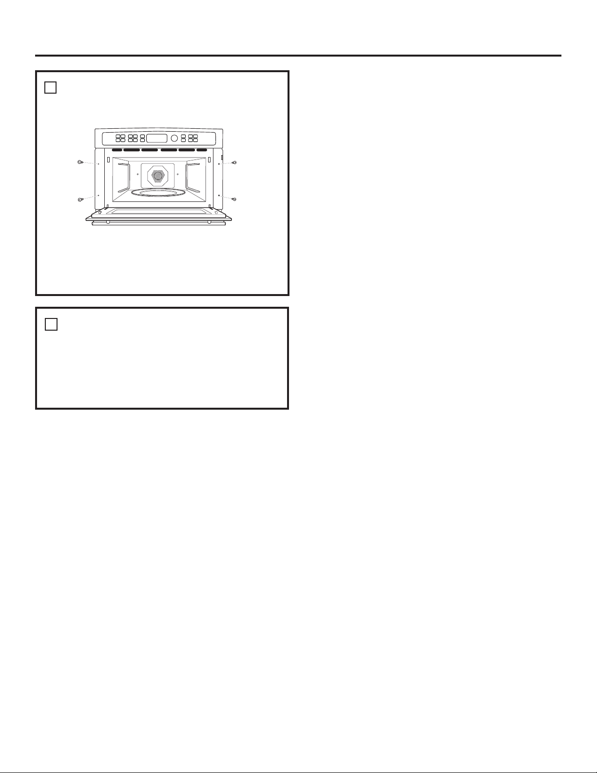
INSTALE LOS TORNILLOS DE
3
MONTAJE
• Realice orificios piloto con el taladro
en los salientes laterales, 2 de cada lado.
• Coloque los tornillos de color combinado
en el saliente lateral.
FINALICE LA INSTALACIÓN
4
Instalación
• Conecte la energía en la fuente. La luz interior
se encenderá al abrir la puerta.
• Consulte el Manual del propietario para
obtener instrucciones acerca de cómo operar
el horno.
Impreso en Corea
 Loading...