

GE PSB9100BL1TS, PSB9100BL2TS, PSB9100DF1BB, PSB9100DF1WW, PSB9100DF2BB Installation Guide
...Page 1
Installation
I structi n
Advantium ®120V
Built-In SpeedCook
Ovens
PSB9100DF
PSB9100SF
49-40689-1
[vlFL59060910
07-15 GE
Espaflol
For a Spanish version of this manual, visit
our Website at GEAppliances.com.
Para consultar una version en espaflol de
este manual de instrucciones, visite nuestro
sitio de internet GEAppliances.com.
Page 2
Safet Information
BEFORE YOU BEGIN
Read these instructions completely and carefully.
IMPORTANT- Sove these instructionsfor
locolinspector'suse.
IM PO RTANT -Observeollgoverning
codes ond ordinonces.
• Note to Installer - Be sure to leave these
instructions with the Consumer.
• Note to Consumer - Keep these instructions
with your Owner's Manual for future reference.
• Skill Level- Installation of this appliance
requires basic mechanical and electrical skills.
• Completion Time- 1 Hour.
• Proper installation is the responsibility of the
installer.
Product failure due to improper installation is
not covered under the warranty. See Owner's
Manual for warranty information.
IMPORTANT- Use thisoven onlyforits
intendedpurpose.Never use the oven forworming
or heotingo room. Prolongeduse of theoven
withoutproperventilotioncon be hozordous.
CAUTION:
For personolsofety,remove house fuse oroven
circuitbreokerbeforebeginninginstollotion
toovoid severeorfotolshock injury.
CONTENTS
Design Information
Models Available ....................................................................2
Product Dimensions and Clearances ..........................4
Tools Required .......................................................................4
Ports Supplied ........................................................................4
Advance Planning ................................................................4
Installation Preparation
Electrical Requirements ....................................................5
Prepare the Opening .....................................................6, 7
Remove the Packaging .......................................................7
Installation Instructions
Step 1, Slide the Oven into the Cutout ........................8
Step 2, Install Bottom Trim ................................................8
Step 3, Install Mounting Screws .....................................8
Step 4, Finalize Installation ...............................................8
MODELS AVAILABLE
Profile Models:
PSB9100DFWW - White
PSB9100DFBB - Block
PSB9100SFSS - Stainless Steel
ACAUTION:
For personolsofety,the mounting surfocemust
be copoble of supportingthe cobinetlood,in
odditiontothe odded weight ofthe 80-pound
oven ond 50-pound drower,plusodditionoloven
loodsofup to 50 pounds or o totolweightofup
to 160 pounds.
ACAUTION:
For personal safety this product cannot be
installed in cabinet arrangements such as on
island, o peninsula or below o countertop.
Page 3
Informaci6n de seguridad
ANTES DE COMENZAR
Lea estas instrucdones par completo y con
detenimiento.
IMPORTANTE - Guardeestasinstrucciones
para el usa de inspectores locales.
IMPORTANTE -Cumplacontodoslos
c6digos y ordenanzas vigentes.
• Nota al instalador- AsegOrese de dejar estas
instrucciones con el Consumidor.
,, Nota al consumidor- Mantenga estas
instrucciones con el Manual del Propietario para
referencia futura.
• Nivel de capacidad - Lainstalaci6n de este
aparato requiere capacidades mecanicas y el6ctricas
b_sicas.
• Tiempo de finaJizaci6n - 1 hora.
La instalaci6n adecuada es responsabilidad
del instalador.
,, La garantia no cubre fallas producidas
par la instalaci6n inadecuada del producto.
Consulte el Manual del propietario para
obtener informaci6n sabre la garantia.
IMPORTANTE - Utiliceestehomo s61ocon
elobjetivopara elque fue creado.Nunca use el
horno para entibiaro colentaruna habitaci6n.
Eluso prolongado delhomo sinuna ventilaci6n
adecuada puede resultarpeligroso.
APRECAUCI6N:
Para seguridad personal,quiteelfusibleo el
interruptor de circuitos de la vivienda antes de
comenzar la instalaci6n a fin de evitar una lesi6n
grave o fatal.
APRECAUCI6N:
Para seguridad personal, la superficie de montaje
debe poder soportar la carga del gabinete,
adem6s de las 80 libras del homo y las BO libras
del caj6n, rods las cargas adicionales del homo de
hasta 50 libras o un peso total de hasta 160 libras.
APRECAUCI6N:
Para su seguridad personal, este producto no
puede set instalado en arreglos de alacena,
coma par ejemplo, islas, peninsulas o debajo de
superficies de trabajo.
Page 4
Design Information
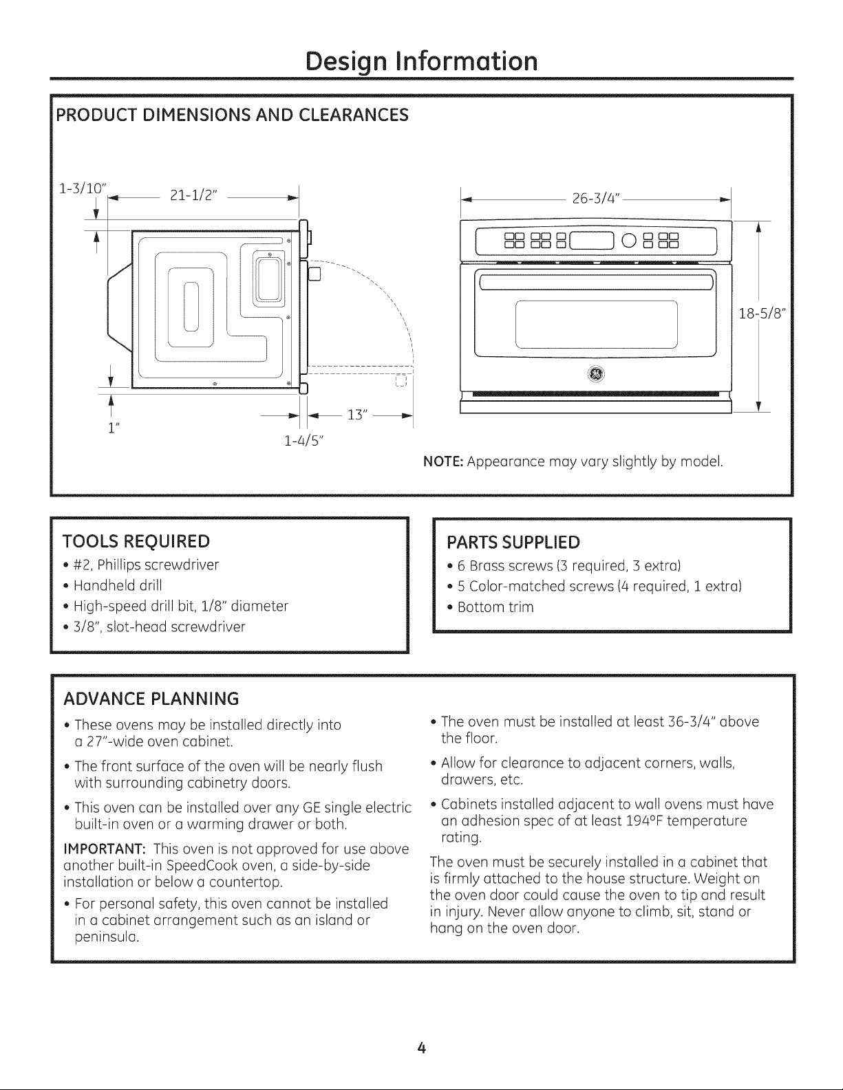
PRODUCT DIMENSIONS AND CLEARANCES
21-1/2"
\
\
1"
TOOLS REQUIRED
• #2, Phillips screwdriver
• Hondheld drill
• High-speed drill bit, 1/8" diameter
,, 3/8", slot-head screwdriver
-,_ 13" _
1-4/5"
26-3/4" _"
O0 O0 0 0 0 O0
I oo oo o_ moo ]
\\
\\
\
\
\\
\
E
L_J
NOTE: Appearance may vary slightly by model.
PARTSSUPPLIED
• 6 Brass screws (3 required, 3 extra)
• 5 Color-matched screws (4 required, 1 extra)
• Bottom trim
18-5/8"
ADVANCE PLANNING
• These ovens may be installed directly into
a 27"-wide oven cabinet.
• The front surface of the oven will be nearly flush
with surrounding cabinetry doors.
• This oven con be installed over any GE single electric
built-in oven or a warming drawer or both.
IMPORTANT: This oven is not approved for use above
another built-in SpeedCook oven, o side-by-side
installation or below o countertop.
• For personal safety, this oven cannot be installed
in o cabinet arrangement such us on island or
peninsula.
• The oven must be installed atleast 36-3/4" above
the floor.
• Allow for clearance to adjacent corners, walls,
drawers, etc.
• Cabinets installed adjacent to wall ovens must hove
on adhesion spec of atleast 194°F temperature
rating.
The oven must be securely installed in a cabinet that
is firmly attached to the house structure. Weight on
the oven door could cause the oven to tip and result
in injury. Never allow anyone to climb, sit, stand or
hang on the oven door.
4
Page 5
Installation Preparation
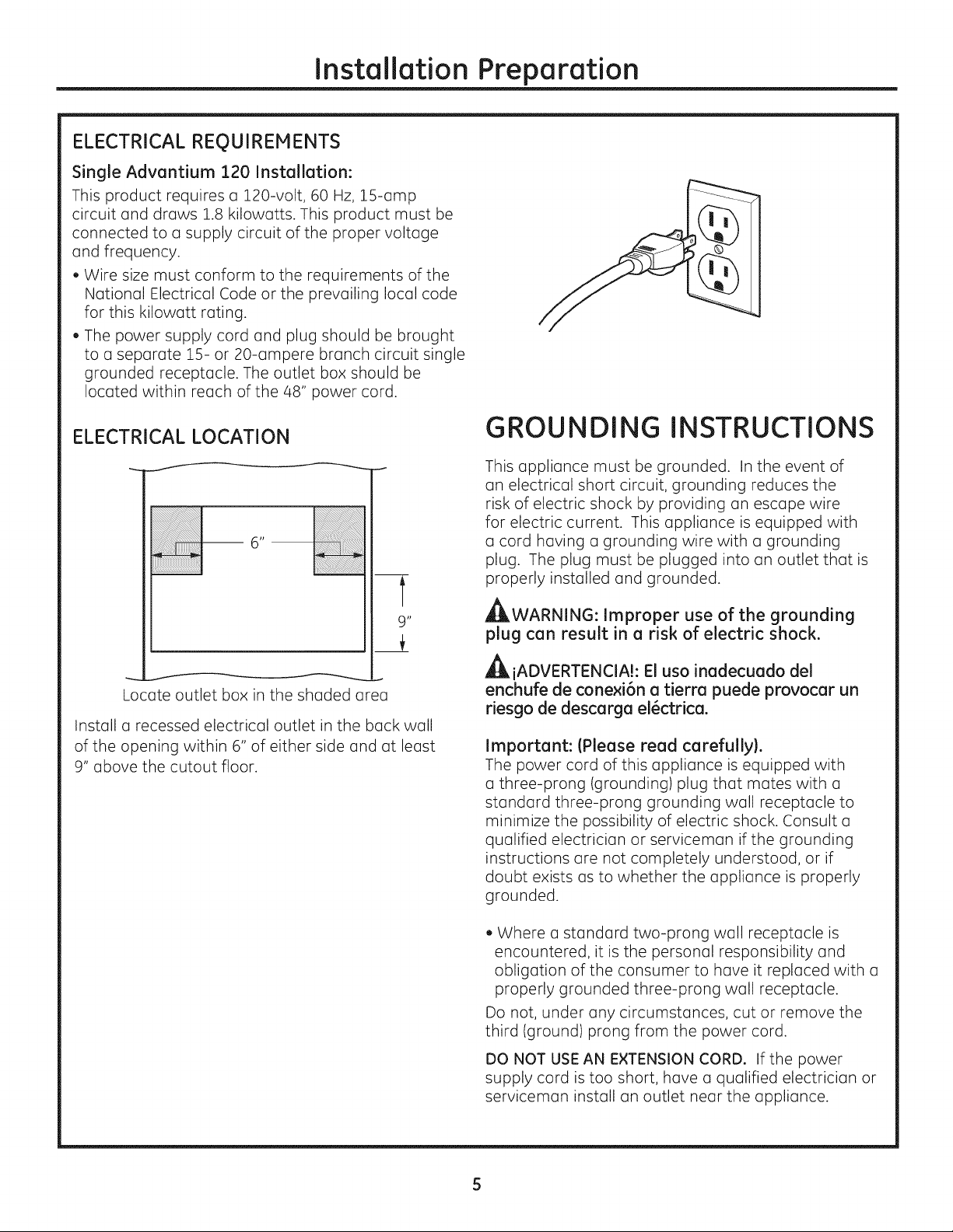
ELECTRICAL REQUIREMENTS
Single Advantium 120 Installation:
This product requires a 120-volt, 60 Hz, 1S-amp
circuit and draws 1.8 kilowatts. This product must be
connected to a supply circuit of the proper voltage
and frequency.
• Wire size must conform to the requirements of the
National Electrical Code or the prevailing local code
for this kilowatt rating.
• The power supply cord and plug should be brought
to a separate 15- or 20-ampere branch circuit single
grounded receptacle. The outlet box should be
located within reach of the 48" power cord.
ELECTRICAL LOCATION
--6"
t
9"
Locate outlet box in the shaded area
Install a recessed electrical outlet in the back wall
of the opening within 6" of either side and at least
9" above the cutout floor.
GROUNDING INSTRUCTIONS
This appliance must be grounded. In the event of
on electrical short circuit, grounding reduces the
risk of electric shock by providing on escape wire
for electric current. This appliance is equipped with
a cord having a grounding wire with a grounding
plug. The plug must be plugged into an outlet that is
properly installed and grounded.
_WARNING: Improper use of the grounding
plug can result in a risk of electric shock.
AiADVERTENCIA!: El usa inadecuado del
enchufe de conexi6n a tierra puede provocar un
riesgo de descarga el_ctrica.
Important: IPlease read carefully}.
The power cord of this appliance is equipped with
a three-prong (grounding) plug that mutes with a
standard three-prong grounding wall receptacle to
minimize the possibility of electric shock. Consult a
qualified electrician or serviceman if the grounding
instructions are not completely understood, or if
doubt exists as to whether the appliance is properly
grounded.
• Where a standard two-prong wall receptacle is
encountered, it is the personal responsibility and
obligation of the consumer to have it replaced with a
properly grounded three-prong wall receptacle.
Do not, under any circumstances, cut or remove the
third (ground) prong from the power cord.
DO NOT USE AN EXTENSION CORD. If the power
supply cord is too short, have a qualified electrician or
serviceman install an outlet near the appliance.
Page 6
Installation Preparation
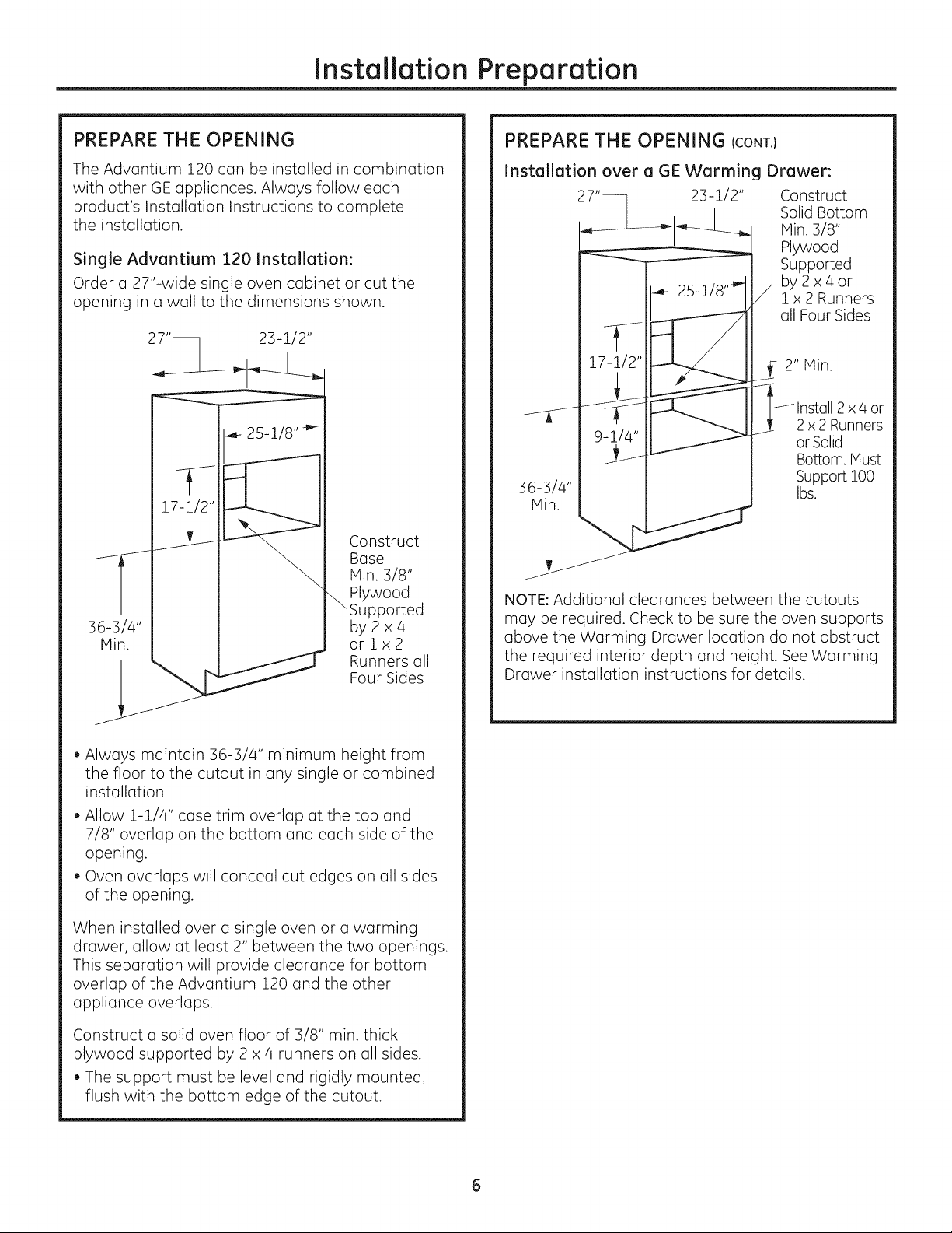
PREPARE THE OPENING
The Advantium 120 can be installed in combination
with other GE appliances. Always follow each
product's Installation Instructions to complete
the installation.
Single Advantium 120 Installation:
Order a 27"-wide single oven cabinet or cut the
opening in a wall to the dimensions shown.
2_ _ 23-1/2"
n
Construct
Base
Hin. 3/8"
Plywood
Supported
3
by2x4
orlx2
Runners all
Four Sides
PREPARE THE OPENING (CONT.}
Installation over a GE Warming Drawer:
23-1/2"
4- 25_1/8''_"
17-1/2"
W
9-1/4"
36-3/4"
Hin.
NOTE: Additional clearances between the cutouts
may be required. Check to be sure the oven supports
above the Warming Drawer location do not obstruct
the required interior depth and height. See Warming
Drawer installation instructions for details.
Construct
Solid Bottom
Hin. 3/8"
Plywood
Supported
by2x4or
lx 2 Runners
all Four Sides
7_ 2" lVlin
]Jlnstall x or
2 4
2 x 2 Runners
or Solid
Bottom. Hust
Support 100
bs.
• Always maintain 36-3/4" minimum height from
the floor to the cutout in any single or combined
installation.
Allow 111/4 '' case trim overlap at the top and
7/8" overlap on the bottom and each side of the
opening.
Oven overlaps will conceal cut edges on all sides
of the opening.
When installed over a single oven or a warming
drawer, allow at least 2" between the two openings.
This separation will provide clearance for bottom
overlap of the Advantium 220 and the other
appliance overlaps.
Construct a solid oven floor of 3/8" min. thick
plywood supported by 2 x 4 runners on all sides.
The support must be level and rigidly mounted,
flush with the bottom edge of the cutout.
Page 7
Installation Preparation
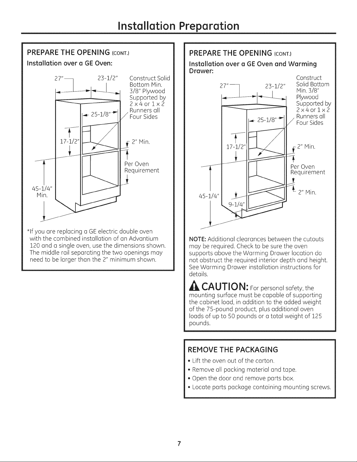
PREPARE THE OPENING CCONT.I
Installation over a GE Oven:
Construct Solid
Bottom Hin.
3/8" Plywood
Supported by
2x4orlx2
Runners oll
Four Sides
17-1/2"
2" Min.
Per Oven
Requirement
PREPARE THE OPENING ICONT.}
Installation over a GE Oven and Warming
Drawer:
Construct
27"-- 23-1/2" Solid Bottom
45-1/4"
Hin. 3/8"
Plywood
Supported by
2x4orlx2
Runners all
Four Sides
- 2" Min.
Per Oven
Requirement
2" Min.
*If you ore replacing u GE electric double oven
with the combined instollotion of on Advontium
120 undo single oven, use the dimensions shown.
The middle toil seporuting the two openings muy
need to be lurger thun the 2" minimum shown.
NOTE: Additionul cleurunces between the cutouts
muy be required. Check to be sure the oven
supports obove the Worming Drower locution do
not obstruct the required interior depth ond height.
See Worming Drawer installation instructions for
detuils.
CAUTION: Forpersonul sofety, the
mounting surfuce must be cupoble of supporting
the cabinet loud, in uddition to the udded weight
of the 75-pound product, plus udditionul oven
Ioods of up to 50 pounds or o totol weight of 125
pounds.
REMOVE THE PACKAGING
• Lift the oven out of the corton.
• Remove oil pocking moteriol und tope.
• Open the door und remove ports box.
• Locote ports pockoge contuining mounting screws.
7
Page 8

Installation
[] SLIDE THE OVEN INTO THE CUTOUT
CAUTION: Two people are required
to lift the oven into the opening. Grasp the bottom
at the front and rear. DO NOT USETHE HANDLE
TO LIFT THE OVEN. DAMAGE WILL OCCUR!
PRECAUCI6N: Serequieren
dos personas para levantar el homo e introducirlo
en la abertura. Agarre la parte inferior par delante
y par detr6s. NO USE LA IANIJA PARA LEVANTAR
EL HORNO. iPUEDE DA--ARSE!
• Lift and hold the oven at the front of the opening.
Hold the oven at a 45° angle and plug in the
power cord.
• Carefully, slide the oven into the cabinet part
way. Leave the oven a few inches forward of the
cabinet frame.
[_] INSTALL BOTTOM TRIM
• Align bottom trim tabs to slots in the bottom
of the oven.
_L
_ / ¸
T _ T T
i
I I
Secure the bottom trim to the bottom of the oven
using 3 brass screws provided.
INSTALL MOUNTING SCREWS
[][][][] [][] 0 _ O _ [][]
" DID [] [][] ]
• Check to be sure the power cord is not trapped
under the oven or along the sides of the oven.
;:":_t)j
r M }_3
• Drill pilot holes through the side flanges, 2 on each
side.
Drive the color-matched screws into the side
flange.
141FINALIZE INSTALLATION
• Turn the power on at the source. The interior light
should come on when the door is opened.
Refer to the Owner's Manual for operating
instructions.
8 Printed in Korea
Page 9
®
Instrucc
e
de instalaci6n
Hornos de cocci6n
r6pida empotrados
de 120V Advantium ®
PSB9100DF
PSB9100SF
49-40689-i
MFL59060910
07-13 GE
Page 10

Informaci6n de seguridad
ANTES DE COMENZAR
Lea estas instrucdones par completo y con
detenimiento.
IMPORTANTE - Guardeestasinstrucciones
para el usa de inspectores locales.
IMPORTANTE -Cumplacontodoslos
c6digos y ordenanzas vigentes.
• Nota al instalador- AsegGrese de dejar estas
instrucciones con el Consumidor.
• Nota al consumidor- Mantenga estas
instrucciones con el Manual del Propietario para
referencia futura.
• Nivel de capacidad - Lainstalaci6n de este
aparato requiere capacidades mecanicas y el6ctricas
b_sicas.
• Tiempo de finaJizaci6n - 1 hora.
• La instalaci6n adecuada es responsabilidad
del instalador.
• La garantia no cubre fallas producidas
par la instalaci6n inadecuada del producto.
Consulte el Manual del propietario para
obtener informaci6n sabre la garantia.
CONTENIDOS
Informaci6n sobre el dise_o
Modelos disponibles ........................................................2
Dimensiones del producto y espacio libre ............3
Herramientas necesarias ..............................................3
Partes incluidas ..................................................................B
Planificaci6n anticipada .................................................B
Preparaci6n para la instalaci6n
Requisitos el@ctricos ........................................................4
Prepare la abertura .....................................................5, 6
Retire el embalaje .............................................................6
Instalaci6n
Paso 1, deslice el horno dentro del carte .............7
Paso 2, instale el recorte inferior ...............................7
Paso 3, instale los tornillos de montaje ..................8
Paso 4, finalice la instalaci6n ......................................8
MODELOS DISPONIBLES
IMPORTANTE - Utiliceestehomo s61ocon
elobjetivopara elque fue creado.Nunca use el
horno para entibiaro colentaruna habitaci6n.
Eluso prolongado delhomo sinuna ventilaci6n
adecuada puede resultarpeligroso.
APRECAUCI6N:
Para seguridad personal,quiteelfusibleo el
interruptor de circuitos de la vivienda antes de
comenzar la instalaci6n a fin de evitar una lesi6n
grave o fatal.
APRECAUCI6N:
Para seguridad personal, la superficie de montaje
debe poder soportar la carga del gabinete,
adem6s de las 80 libras del homo y las B0 libras
del caj6n, rods las cargas adicionales del homo de
hasta 50 libras o un peso total de hasta 160 libras.
APRECAUCI6N:
Para su seguridad personal, este producto no
puede set instalado en arreglos de alacena,
coma par ejemplo, islas, peninsulas o debajo de
superficies de trabajo.
Modelos Profile:
PSB9100DFWW- Blanco
PSBg100DFBB- Negro
PSBg100SFSS- Acero inoxidable
Page 11
Informaci6n sobre el dise5o
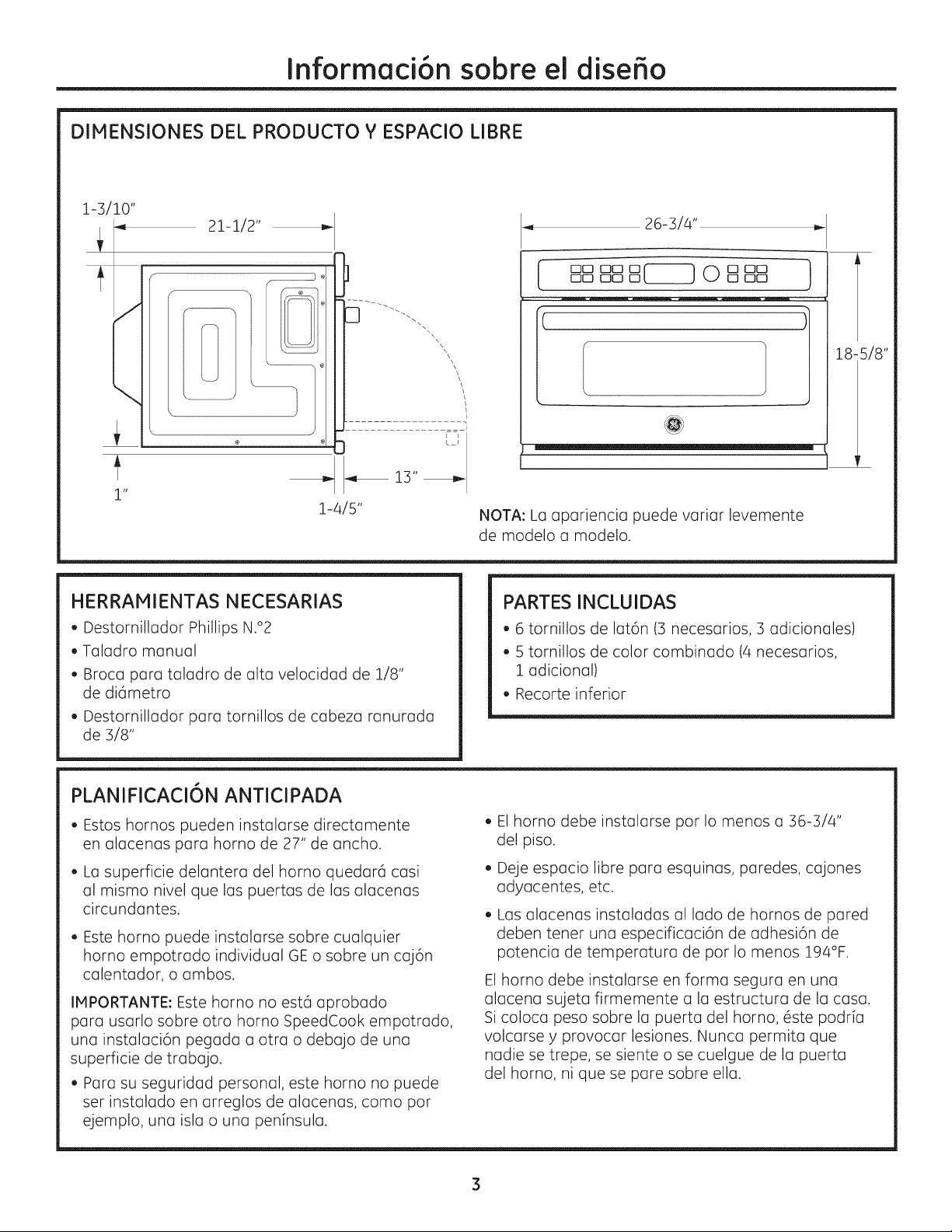
DIMENSIONES DEL PRODUCTO Y ESPACIO LIBRE
l-s/lo"
21-1/2"
I _ _ 13" _
1"
1-4/5"
HERRAMIENTAS NECESARIAS
• Destomillador Phillips N.°2
• Taladro manual
• Broca para taladro de alta velocidad de 1/8"
de die,metro
• Destomillador para tornillos de cabeza ranurada
de 3/8"
26-3/4"
O0 O0 0
[ oo oooo _ []ooooo ]
\
\
L
NOTA: La apariencia puede variar levemente
de modelo a modelo.
! :
PARTES INCLUIDAS
• 6 tornillos de lat6n (3 necesarios, 3 adicionales)
• 5 tomillos de color combinado (4 necesarios,
1 adicional)
• Recorte inferior
18-5/8"
PLANIFICACI6N ANTICIPADA
• Estos hornos pueden instalarse directamente
en alacenas para horno de 27" de ancho.
• Lasuperficie delantera del homo quedard casi
al mismo nivel que las puertas de las alacenas
circundantes.
• Este horno puede instalarse sabre cualquier
horno empotrado individual GE o sabre un caj6n
calentador, o ambos.
IMPORTANTE: Este homo no estd aprobado
para usarlo sabre otto horno SpeedCook empotrado,
una instalaci6n pegada a otra o debajo de una
superficie de trabajo.
• Para su seguridad personal, este homo no puede
ser instalado en arreglos de alacenas, coma par
ejemplo, una isla o una peninsula.
• El homo debe instalarse par Io menos a 36-3/4"
del piso.
• Dejeespacio libre para esquinas, paredes, cajones
adyacentes, etc.
• Losalacenas instaladas al lado de hornos de pared
deben tenet una especificaci6n de adhesi6n de
potencia de temperatura de par Io menos 194°F.
Elhorno debe instalarse en forma segura en una
alacena sujeta firmemente a la estructura de la casa.
Sicoloca peso sabre la puerta del homo, 6ste podria
volcarse y provocar lesiones. Nunca permita que
nadie se trepe, se siente o se cuelgue de la puerta
del homo, ni que se pare sabre ella.
Page 12

Preparaci6n para la instalaci6n
REQUISlTOS ELI_CTRICOS
Instalaci6n 6nica del Advantium 120:
Este producto requiere un circuito de 120 voltios,
60 Hz, 15 amp y toma 1.8 kilovatios. Este producto
debe conectarse a un circuito de alimentaci6n del
voltaje y la frecuencia adecuados.
• El tama_o del cable debe respetor los requisitos del
C6digo EI6ctrico Nacional INational Electrical Code}
o el c6digo local en vigencia para esta potencia de
kilowatios.
El cable y el enchufe de suministro de energTa deben
Ilevarse hacia un recept6culo individual conectado
a tierra, en un circuito derivado de 15 6 20
amperios. Lo caja de distribuci6n debe estar
ubicada al alcance del cable de alimentaci6n de 48".
UBICACION ELI_CTRICA
6n
1
9"
Coloque la caja del tomacorriente
en el c_reasombreada
Instale un tomacorriente el6ctrico empotrado
en la pared posterior de la obertura a 6" de coda
lado y par Io menos a 9" sabre el piso del carte.
INSTRUC CIONES DE
CONEXION A TIERRA
Este electrodom6stico deberc_ estar conectado a
tierra. En caso de que se produzca un cortocircuito,
la conexi6n a tierra reduce el riesgo de descarga
el6ctrica, brindando un cable de escape de la
corriente el6ctrica. Este electrodom6stico estc_
equipado con un cable de corriente que posee un
cable de conexi6n a tierra con un enchufe a tierra.
El enchufe se deberc_ enchufar en un tomacorriente
instalado y conectado a tierra de forma adecuada.
_iADVERTENCIA!: Eluso inadecuado del
enchufe de conexi6n a tierrapuede provocar un
riesgode descarga el(_ctrica.
Importante: (Se solicita leer detenidamente).
El cable de corriente de este electrodom6stico
cuenta con un enchufe de 5 clavijas (con cable a
tierra) que se conecta a un tomacorriente de pared
estdmdar de 3 clavijas para minimizar la posibilidad
de descargas el6ctricas. Consulte a un electricista
calificado o al personal del servicio t6cnico en caso
de que los instrucciones de conexi6n a tierra no se
entiendan completamente, o si tiene dudas sabre
si el electrodom6stico estdJconectado a tierra de
forma apropiada.
• Para el usa de este artefacto, es responsabilidad
y obligaci6n del consumidor cambiar un
tomacorriente de pared estc_ndar de dos patas par
uno de tres patas con adecuada conexi6n a tierra.
Bajo ninguna circunstancia carte o quite la tercera
pata (a tierra) del cable el6ctrico.
NO USE UN PROLONGADOR. Si el cable de corriente
es demasiado corto, solicite a un electricista calificado
o al personal del servicio t6cnico que instale un
tomacorriente cerca del electrodom6stico.
4
Page 13

Preparaci6n para la instalaci6n
PREPARE LA ABERTURA
ElAdvantium 120 puede instalarse
en combinaci6n con otros aparatos GE.Siempre
siga las indicaciones de instalaci6n de carla
producto para realizar la instalaci6n.
Instalaci6n 6nica del Advantium 120:
Pida una alacena para horno 0nico de 27"
de ancho o corte la abertura en la pared
de acuerdo con las dimensiones indicadas.
2_ 23-1/2"
25-1/8 ''_
17-1/2"
V
Plin.
36-3/4"
• Siempre mantenga uno alturo minima
de 36-3/4" desde el suelo hosto el corte en todas
las instalaciones 0nicas o combinadas.
• Tenga en cuenta el espacio para la superposici6n
de un recorte de caja de 1-1/4" en la parte
superior, 7/8" en la parte inferior y a cada lado
de la abertura.
• Lo superposici6n de los recortes ocultor6
los bordes cortados en todos los lados
de la abertura.
Basede
construcci6n
demadera
\contrachapada
demin.3/8"
sostenidapor
correderas
de2x46Zx2
enloscuatrolados
PREPARE LA ABERTURA (CONT,)
Instalaci6n sobre un caj6n calentador GE:
Construya una
baseinferior s61ida
de madera
23-1/2"
_- 25-1/8 ''_
A
Min.
s6-s/4"
NOTA: Es posible que se requieran espacios
adicionales entre los cortes. Verifique para
asegurarse de que los soportes del homo sobre
el caj6n calentador no obstruyan la profundidad
y la altura interior necesarias. Consulte
las instrucciones de instalaci6n del caj6n
calentador para obtener m6s detalles.
contrachapada
de min. S/8"
de espesor,
sostenidapor
2x461x2
/en loscuatro lados
Min. 2"
lnstale
correderas
de2x4
62x2
o una base
inferior s61ida.
Debe sostener
100 lb.
Cuando se instale sobre un homo 0nico o un
caj6n calentador, deje un espacio de por Io
menos 2" entre las dos aberturas. Esta separaci6n
proporcionar6 el espacio necesario para la
superposici6n del recorte inferior del Advantium
120 y la superposici6n de los dem6s elementos
del aparato.
Construya un piso de horno s61ido para el homo
de madera contrachapoda de min. 3/8" de espesor
sostenido por correderas de 2 x 4 en todos los
lados.
• El sost6n debe estor nivelado y montodo con
rigidez, empotrado en el borde inferior del corte.
Page 14

Preparaci6n para la instalaci6n
PREPARE LA ABERTURA (CONT.)
Instalaci6n sobre un homo GE:
17-1/2"
Requisito por
homo
Plin.
45-1/4"
Construya una
base inferior
s61ida de min.
3/8", sostenida
por correderas
de2x46
I x 2 en los
cuatro lados
Min. 2"
PREPARE LA ABERTURA (CONT.)
Instalaa6n sobre un horno y un caj6n
calentador GE:
Construya una
base inferior
s61idade rain.
3/8", sostenida
por correderas
de2x46
i x 2 en los
cuatro lados
Req,uisito
por norno
45-1/4"
*Si est6 reemplazando un horno el@ctrico
doble GE por la instalaci6n combinada de
un Advantium 120y un homo 0nico, use las
dimensiones indicadas. Es posible que el riel
del medio que separa las dos aberturas deba
set mayor que el minimo de 2" indicado.
NOTA: Es posible que se requieran espacios
adicionales entre los cortes. Verifique para
asegurarse de que los soportes del homo sobre
el caj6n calentador no obstruyan la profundidad
y la altura interior necesarias. Consulte
las instrucciones de instalaci6n del caj6n
calentador para obtener m6s detalles.
PRECAUCI6N: Parasu seguridad
personal, la superficie de montaje debe poder
sostener la carga de la alacena, adem6s del
peso adicional de este producto de 7S libras
aproximadamente, m6s las cargas adicionales
del homo de basra 50 libras o un peso total
de 125 libras.
RETIRE EL EMBALAJE
• Saque el homo de la caja.
• Retire todo el material y la cinta de embalaje.
• Abra la puerta y saque la caja con las piezas.
• Tome el paquete de repuestos que contiene
los tornillos de montaje.
6
Page 15

Instalaci6n
FTIDESLICE EL HORNO DENTRO
DEL CORTE
PRECAUCI6N: Serequieren
dos personas para levantarelhomo e introducirlo
en Ioabertura.Agarre Ioporteinferiorpar delante
y par detr6s.NO USE LA MANIJA PARA LEVANTAR
EL HORNO. iPUEDE DA--ARSE!
• Levonte y sostenga el homo delonte
de la abertura. Sostenga el homo en un 6ngulo
de 45 ° y enchufe el cable de alimentaci6n.
• Con cuidado, deslice porcialmente el horno dentro
de la alacena. Deje que el horno sobresalga
algunas pulgadas de la estructura de la alacena.
[Z] INSTALE EL RECORTE INFERIOR
Alinee las lengOetas del recorte inferior
con los ranuras de la porte inferior del horno.
I ...................._......................_..................................................._..........................................
Ajuste el recorte inferior del horno usando
los 3 tornillos de metal incluidos.
Aseg0rese de que el cable de alimentaci6n
no quede atrapado debajo del homo ni
en los laterales.
Page 16
Instalaci6n
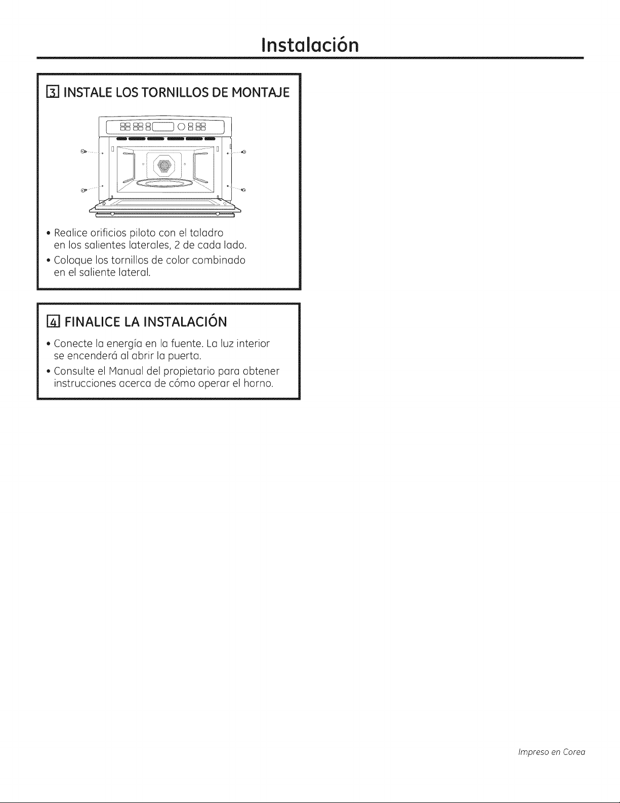
[3] INSTALE LOS TORNILLOS DE MONTAJE
• Realice orificios piloto con el taladro
en los salientes laterales, 2 de cada lado.
• Coloque los tornillos de color combinado
en el saliente lateral.
FINALICE LA INSTALACI6N
• Conecte la energia en la fuente. La luz interior
se encenderd al abrir la puerta.
• Consulte el Manual del propietario para obtener
instrucciones acerca de c6mo operar el horno.
lmpreso en Corea
 Loading...