

Page 1

GE Medical Systems
Technical
Publications
Direction 2259724-100
Revision 22
Proteus XR/a
Operator Manual
0459
Copyright © 2000~2009
By General Electric Company
Operating Documentation
Page 2

PROTEUS XR/a
ii
GE MEDICAL SYSTEMS Operator Manual
REV 22 DIRECTION 2259724-100
This page intentionally left blank
Page 3

PROTEUS XR/a
i
CAUTION
GE MEDICAL SYSTEMS Operator Manual
REV 22 DIRECTION 2259724-100
IMPORTANT!...X-RAY PROTECTION
X-ray equipment if not properly used may cause injury. Accordingly, the
instructions herein contained should be thoroughly read and understood by
everyone who will use the equipment before you attempt to place this equipment
in operation. The General Electric Company, Medical Systems Group, will be glad
to assist and cooperate in placing this equipment in use.
Although this apparatus incorporates a high degree of protection against x-radiation other
than the useful beam, no practical design of equipment can provide complete protection.
Nor can any practical design compel the operator to take adequate precautions to
prevent the possibility of any persons carelessly exposing themselves or others to
radiation.
It is important that everyone having anything to do with x-radiation be properly trained and
fully acquainted with the recommendations of the National Council on Radiation
Protection and Measurements as published in NCRP Reports available from NCRP
Publications, 7910 Woodmont Avenue, Room 1016, Bethesda, Maryland 20814, and of
the International Commission on Radiation Protection, and take adequate steps to protect
against injury.
The equipment is sold with the understanding that the General Electric Medical Systems,
its agents, and representatives have no responsibility for injury or damage which may
result from improper use of the equipment.
Various protective material and devices are available. It is urged that such materials or
devices be used.
Federal law restricts this device to sale by or on the order of a physician.
Page 4
PROTEUS XR/a
ii
CERTIFIED ELECTRICAL CONTRACTOR STATEMENT
If you have any comments, suggestions or corrections to the information in this document,
please write them down, include the document title and document number, and send them to:
GENERAL ELECTRIC MEDICAL SYSTEMS
MANAGER - INFORMATION INTEGRATION
AMERICAS, X-RAY W-622
P.O. BOX 414
MILWAUKEE, WI 53201-0414
GE MEDICAL SYSTEMS Operator Manual
REV 22 DIRECTION 2259724-100
All electrical installations that are preliminary to positioning of the equipment at the site prepared for the
equipment shall be performed by licensed electrical contractors. In addition, electrical feeds into the Power
Distribution Unit shall be performed by licensed electrical contractors. Other connections between pieces of
electrical equipment, calibrations, and testing shall be performed by qualified GE Medical personnel. The
products involved (and the accompanying electrical installations) are highly sophisticated, and special
engineering competence is required. In performing all electrical work on these products, GE will use its own
specially trained field engineers. All of GE’s electrical work on these products will comply with the requirements
of the applicable electrical codes.
The purchaser of GE equipment shall only utilize qualified personnel (i.e., GE’s field engineers, personnel of
third-party service companies with equivalent training, or licensed electricians) to perform electrical servicing on
the equipment.
Page 5

PROTEUS XR/a
iii
GE MEDICAL SYSTEMS Operator Manual
REV 22 DIRECTION 2259724-100
REGULATORY REQUIREMENTS
This product complies with the regulatory requirements of the
following:
Council Directive 93/42/EEC concerning medical devices: the CE label affixed to the
product testifies compliance to the Directive.
The location of the CE label on the product is described page 2-4.
EU Authorized Representative:
GE Medical Systems SCS
283 rue de la Minière
78530 BUC, FRANCE
Green QSD 1990 Standard issued by MDD (Medical Devices Directorate, Department
of Health, UK).
Quality System Regulation issued by the FDA (Food and Drug Administration,
Department of Health, USA).
Underwriter’s Laboratories, Inc. (UL), an independent testing laboratory.
Canadian Standards Association (CSA).
International Electrotechnical Commission (IEC).
The following equipment classifications are applicable to the
product:
Equipment classification with respect to protection from electric shock: Class 1
Degree of protection from electric shock: Type B
Degree of protection against ingress of liquids: not classified
Equipment not suitable for use in the presence of a flammable anaesthetic mixture with
air or with nitrous oxide; mode of operation: continuous
Mode of operation: continuous with intermittent loading
The Proteus XRa has only level 1 EMC susceptibility immunity responses.
UDI Label
Every Proteus XR/a system has an unique marking for identification. The Unique Device
Identification (UDI) marking appears on the product label which is located on system
cabinet.
Page 6

PROTEUS XR/a
iv
GE MEDICAL SYSTEMS Operator Manual
REV 22 DIRECTION 2259724-100
This page intentionally left blank
Page 7

PROTEUS XR/a
v
WARNING
GE MEDICAL SYSTEMS Operator Manual
REV 22 DIRECTION 2259724-100
ELECTROMAGNETIC COMPATIBILITY (EMC)
This product conforms with IEC 60601-1-2:2001+A1:2004 EMC standard for medical
devices.
Note: This equipment generates, uses, and can radiate radio frequency energy. The
equipment may cause or subject to radio frequency interference with other
medical and non–medical devices and radio communications. To provide
reasonable protection against such interference, the Proteus XR/a System (32,
50, 65, 80kW) complies with emissions limits for a Group 1, Class A Medical
Devices and has applicable immunity level as stated in EN IEC 60601-12:2001+A1:2004.
However, there is no guarantee that interference will not occur in a particular
installation. Special precautions and other information regarding EMC provided
in the accompanying documents of this equipment shall be observed during
installation and operation of this equipment.
Note: If this equipment is found to cause interference (which may be determined by
switching the equipment on and off), the user (or qualified service personnel)
should attempt to correct the problem by one or more of the following
measure(s):
Reorient or relocate the affected device(s).
Increase the separating space between the equipment and the affected
device.
Power the equipment from a source different from that of the affected
device.
Consult the point of purchase or service representative for further
suggestions.
Use of accessories, transducers, cables and other parts other than those
specified by the manufacturer of this equipment may result in increased
emissions or decreased immunity of the equipment. The manufacturer is not
responsible for any interference caused either by the use of interconnect
cables other than those recommended, or by unauthorized changes or
modifications to this equipment. Unauthorized changes or modifications could
void the user’s authority to operate the equipment.
Page 8
PROTEUS XR/a
vi
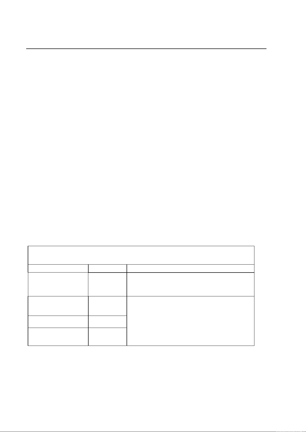
The Proteus XR/a system is suitable for use in the specified electromagnetic environment. The
purchaser or user of the Proteus XR/a system should assure that it is used in an
electromagnetic environment as described below:
Emissions Test
Compliance
Electromagnetic Environment
RF Emissions
CISPR11
Group1
The Proteus XR/a system uses RF energy only for
its internal function. Therefore, its RF emissions are
very low and are not likely to cause any interference
in nearby electronic equipment.
RF Emissions
CISPR11
Class A
The Proteus XR/a system is suitable for use in all
establishments other than domestic and those
directly connected to the public low-voltage power
supply network that supplies buildings used for
domestic purposes.
Harmonic emissions
IEC 61000-3-2
Not
applicable
Voltage fluctuations/
flicker emissions
IEC 61000-3-3
Not
applicable
GE MEDICAL SYSTEMS Operator Manual
REV 22 DIRECTION 2259724-100
ELECTROMAGNETIC COMPATIBILITY (EMC) (CONT.)
Note: To comply with the regulations applicable to an electromagnetic interface for a
Group 1, Class A Medical Device, and to minimize interference risks, the
following requirements shall apply:
All interconnect cables to peripheral devices must be shielded and
properly grounded. Use of cables not properly shielded and grounded
may result in the equipment causing radio frequency interference in
violation of the European Union Medical Device directive and FCC
regulations.
All of those recommended guidance regarding electromagnetic
environment should be followed.
Note: Do not use devices that intentionally transmit RF signals (Cellular Phones,
Transceivers, or Radio Controlled Products) in the vicinity of this equipment as
it may cause performance outside the published specifications. Keep the
power to these type devices turned off when near the equipment.
The medical staff in charge of this equipment is required to instruct technicians,
patients, and others.
Guidance and manufacturer’s declaration – Electromagnetic Emissions
ELECTROMAGNETIC COMPATIBILITY (EMC) (CONT.)
Page 9
PROTEUS XR/a
vii
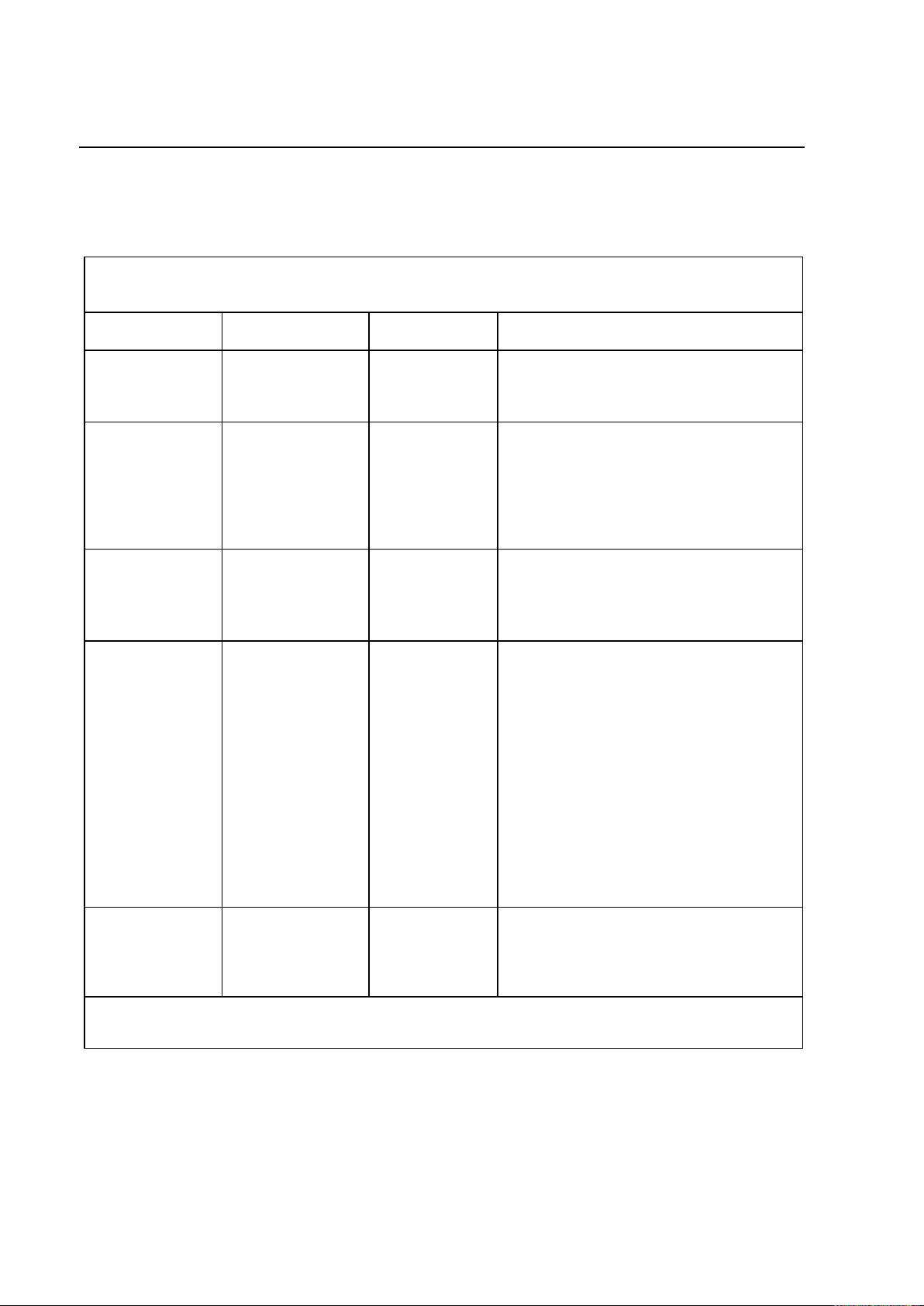
The Proteus XR/a system is suitable for use in the specified electromagnetic environment. The
purchaser or user of the Proteus XR/a system should assure that it is used in an electromagnetic
environment as described below:
Immunity Test
IEC 60601-1-2
Test Level
Compliance
Level
Electromagnetic Environment
Electrostatic
discharge (ESD)
IEC 61000-4-2
6 kV contact
8 kV air
6 kV contact
8 kV air
Floors are wood, concrete, or ceramic
tile, or floors are covered with synthetic
material and the relative humidity is at
least 30 %.
Electrical fast
transient/burst
IEC 61000-4-4
2 kV for power
supply lines
1 kV for
input/output
lines
2 kV for
power supply
lines
1 kV for
input/output
lines
Mains power quality is that of a typical
commercial and/or hospital environment
Surge
IEC 61000-4-5
1 kV differential
mode
2 kV common
mode
1 kV
differential
mode
2 kV common
mode
Mains power quality is that of a typical
commercial and/or hospital environment.
Voltage dips,
short
interruptions and
voltage
variations on
power supply
input lines
IEC 61000-4-11
< 5 % UT
(> 95 % dip in UT)
for 0.5 cycle
40 % UT
(60 % dip in UT)
for 5 cycles
70 % UT
(30 % dip in UT)
< 5 % UT
(> 95 % dip in UT)
for 5 s
0 % UT for 5
sec
Mains power quality is that of a typical
commercial and/or hospital environment.
If the user of the Proteus XR/a system
requires continued operation during
power mains interruptions, it is
recommended that the Proteus XR/a
system be powered from an
uninterruptible power supply or a battery.
Power
frequency
(50/60 Hz)
magnetic field
IEC 61000-4-8
3 A/m
3 A/m
Power frequency magnetic fields are at
levels characteristic of a typical location
in a typical commercial and/or hospital
environment.
Note: These are guidelines. Actual conditions may vary.
GE MEDICAL SYSTEMS Operator Manual
REV 22 DIRECTION 2259724-100
Guidance and manufacturer’s declaration - Electromagnetic Immunity (1)
ELECTROMAGNETIC COMPATIBILITY (EMC) (CONT.)
Page 10
PROTEUS XR/a
viii
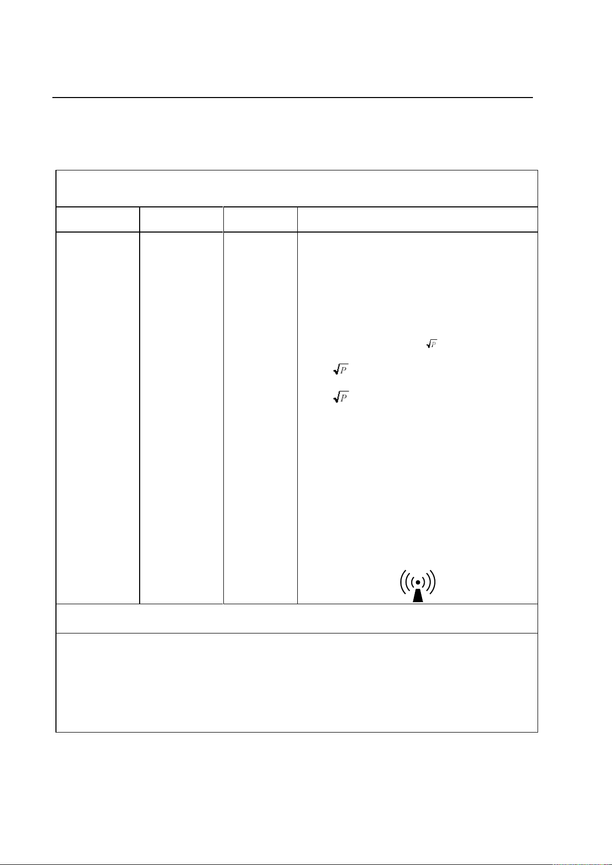
The Proteus XR/a system is suitable for use in the specified electromagnetic environment. The
purchaser or user of the Proteus XR/a system should assure that it is used in an electromagnetic
environment as described below:
Immunity
Test
IEC 60601-1-2
Test Level
Compliance
Level
Electromagnetic Environment
Conducted RF
IEC 61000-4-6
Radiated RF
IEC 61000-4-3
3 V
150 kHz to
80 MHz
3 V/m
80 kHz to
800 MHz
[V1 =] 3 V
[E1=] 3 V/m
Portable and mobile RF communications
equipment are used no closer to any part of the
[EQUIPMENT and/or SYSTEM], including cables,
than the recommended separation distance
calculated from the equation appropriate for the
frequency of the transmitter.
Recommended separation distance
d= 1.2
d= 1.2 80 MHz to 800 MHz
d= 2.3 800 MHz to 2,5 GHz
Note: P is the power rating of the transmitter in
watts (W) according to the transmitter
manufacturer and d is the recommended
separation distance in meters (m).
Field strengths from fixed RF transmitters, as
determined by an electromagnetic site survey,*
are less than the compliance level in each
frequency range.**
Interference may occur in the vicinity of
equipment marked with the following symbol:
NOTE 1 At 80 MHz and 800 MHz, the higher frequency range applies.
NOTE 2 These guidelines may not apply in all situations. Electromagnetic propagation is affected by absorption
and reflection from structures, objects and people.
*Field strengths from fixed transmitters, such as base stations for cellular telephones and land mobile radios,
amateur radio, AM and FM radio broadcast, and TV broadcast cannot be estimated accurately. To assess the
electromagnetic environment due to fixed RF transmitters, an electromagnetic site survey should be performed. If
the measured field strength exceeds the RF compliance level above, observe the Proteus XR/a system to
verify normal operation in each use location. If abnormal performance is observed, additional measures may be
necessary, such as re-orienting or relocating the [EQUIPMENT and/or SYSTEM].
**Over the frequency range 150 kHz to 80 MHz, field strengths are less than 3 V/m.
The Recommended Separation Distances are listed in the next table.
Note: These are guidelines. Actual conditions may vary.
GE MEDICAL SYSTEMS Operator Manual
REV 22 DIRECTION 2259724-100
Guidance and manufacturer’s declaration - Electromagnetic Immunity (2)
ELECTROMAGNETIC COMPATIBILITY (EMC) (CONT.)
Page 11
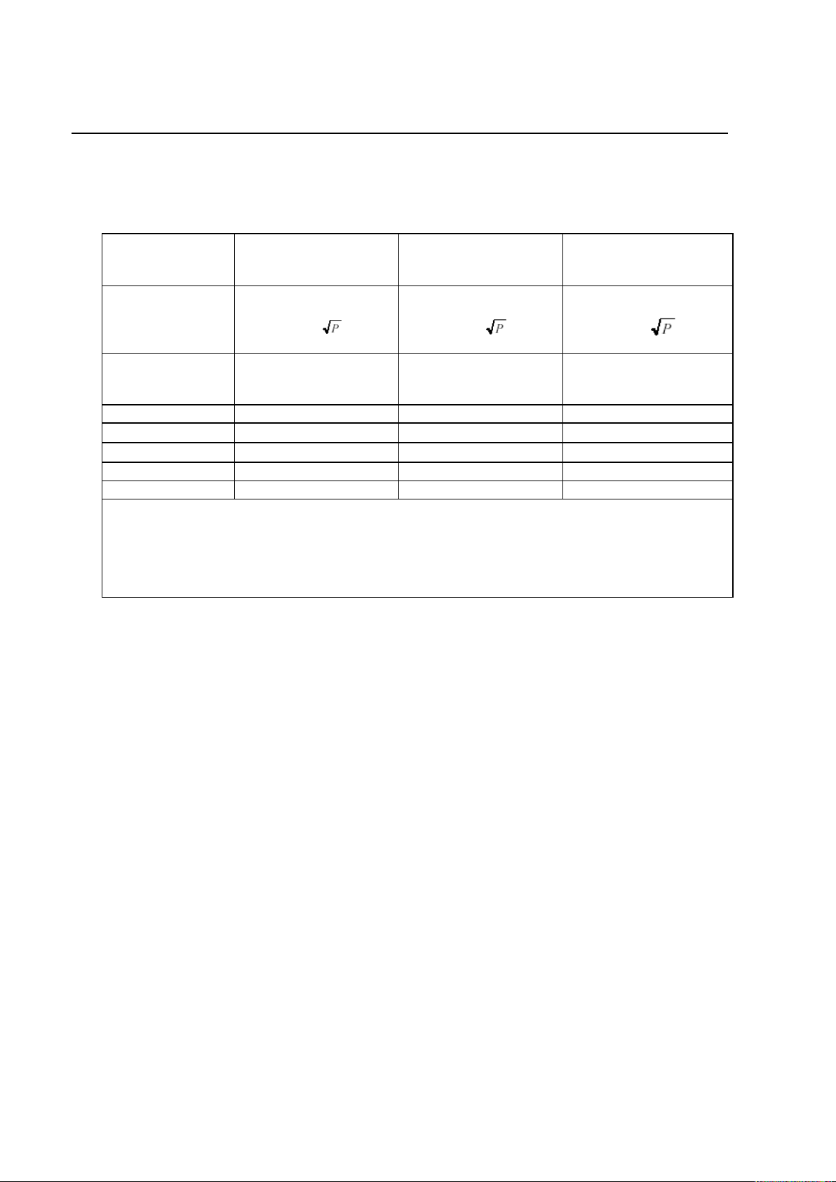
PROTEUS XR/a
ix
Frequency of
Transmitter
150KHz to 80 MHz
80 MHz to 800 MHz
800 MHz to 2,5 GHz
Equation
d= 1.2
d= 1.2
d= 2.3
Rated Power of
Transmitter
(W)
DISTANCE
(meters)
DISTANCE
(meters)
DISTANCE
(meters)
0.01
0.12
0.12
0.23
0.1
0.38
0.38
0.73
1
1.2
1.2
2.3
10
3.8
3.8
7.3
100
12
12
23
For transmitters rated at a power not listed above, the DISTANCE can be estimated using the
equation in the corresponding column, where P is the power rating of the transmitter in watts (W)
according to the transmitter manufacturer.
Note: These are guidelines. Actual conditions may vary.
GE MEDICAL SYSTEMS Operator Manual
REV 22 DIRECTION 2259724-100
Recommended Separation Distances for Portable and Mobile RF Communications
Equipment and the Proteus XR/a system
Page 12

PROTEUS XR/a
x
GE MEDICAL SYSTEMS Operator Manual
REV 22 DIRECTION 2259724-100
This page intentionally left blank
Page 13

PROTEUS XR/a
xi
WARNING
WARNING
WARNING
WARNING
WARNING
WARNING
WARNING
WARNING
WARNING
WARNING
WARNING
WARNING
WARNING
GE MEDICAL SYSTEMS Operator Manual
REV 22 DIRECTION 2259724-100
SAFETY
ELECTRIC SHOCK HAZARD! DO NOT REMOVE COVERS OR PANELS.
GENERATOR CABINET CONTAINS HIGH VOLTAGE CIRCUITS FOR GENERATING
AND CONTROLLING X-RAYS. PREVENT POSSIBLE ELECTRIC SHOCK BY
LEAVING COVERS AND PANELS ON THE EQUIPMENT. THERE ARE NO
OPERATOR SERVICEABLE PARTS OR ADJUSTMENTS INSIDE THE CABINETS
UNDER THE TABLE. ONLY TRAINED AND QUALIFIED PERSONNEL SHOULD BE
PERMITTED ACCESS TO THE INTERNAL PARTS OF THIS EQUIPMENT.
FOR CONTINUED SAFE USE OF THIS EQUIPMENT, FOLLOW THE INSTRUCTIONS
CONTAINED IN THIS OPERATING MANUAL. STUDY THIS MANUAL CAREFULLY
BEFORE USING THE EQUIPMENT AND KEEP IT AT HAND FOR QUICK
REFERENCE.
RADIOGRAPHIC EQUIPMENT MUST BE OPERATED BY QUALIFIED PERSONNEL
AND ONLY AFTER SUFFICIENT TRAINING.
UNITED STATES FEDERAL LAW RESTRICTS THIS DEVICE TO USE BY OR ON THE
ORDER OF A PHYSICIAN.
IT IS THE RESPONSIBILITY OF THE OPERATOR TO ENSURE THE SAFETY OF THE
PATIENT WHILE THE MACHINE IS IN OPERATION BY CHECKING PROPER
PATIENT POSITIONING AND USING THE EQUIPMENT PROTECTIVE DEVICES.
TO AVOID INJURY TO FINGERS AND HANDS OF PATIENT AND OPERATOR
CAUSED BY TABLE TOP MOVEMENT, HANDS MUST BE KEPT AWAY FROM
TABLE TOP EDGES AT ALL TIMES.
USE A SID AS LARGE AS POSSIBLE IN ORDER TO KEEP THE ABSORBED DOSE
TO THE PATIENT AS LOW AS REASONABLY ACHIEVABLE.
IT IS THE RESPONSIBILITY OF THE OPERATOR TO PROVIDE MEANS FOR AUDIO
AND VISUAL COMMUNICATION WITH THE PATIENT FROM THE CONTROL ROOM.
PERFORM PERIODIC MAINTENANCE TO ENSURE CONTINUED SAFE USE OF THE
EQUIPMENT. (See chapter 11 Planned Maintenance).
IF ANY SAFETY PROBLEM OCCURS, PLEASE STOP USING THIS DEVICE AND
CONTACT OUR SERVICE AT ONCE.
RESTRICT ACCESS TO THE EQUIPMENT IN ACCORDANCE WITH LOCAL
REGULATIONS FOR RADIATION PROTECTION.
TO AVOID THE RISK OF ELECTRIC SHOCK, THIS EQUIPMENT MUST ONLY BE
CONNECTED TO A SUPPLY MAINS WITH PROTECTIVE EARTH.
FOR DIAGNOSTIC X-RAY EQUIPMENT SPECIFIED TO BE USED IN COMBINATION
WITH ACCESSORIES OR OTHER ITEMS NOT FORMING PART OF THE SAME,
PLEAE PAY ATTENTION TO THE POSSIBLE ADVERSE EFFECT ARISING FROM
MATERIALS LOCATED IN THE X-RAY BEAM. REFER TO THE TABLE BELOW FOR
MAXIMUM ATTENUATION EQUIVALENT OF POSSIBLE MATERIALS LOCATED IN
THE X-RAY BEAM.
Page 14

PROTEUS XR/a
xii
CAUTION
CAUTION
GE MEDICAL SYSTEMS Operator Manual
REV 22 DIRECTION 2259724-100
Always be alert to safety when you operate this equipment. You must be familiar
enough with the equipment to recognize any malfunctions that can be a hazard. If
a malfunction occurs or a safety problem is known to exist, do not use this
equipment until qualified personnel correct the problem.
Apply necessary sterilization with 75% medical Alcohol to components which are
possible to be contacted with the patients, such as Table top, Wall Stand
(including SG120 Wall Stand) front panel, etc.
Page 15

PROTEUS XR/a
xiii
GE MEDICAL SYSTEMS Operator Manual
REV 22 DIRECTION 2259724-100
ENVIRONMENTAL PROTECTION
WITH THE DISPOSAL OF WASTE PRODUCTS, RESIDUES AND EQUIPMENT
ACCESSORIES THAT ARE OUT OF THEIR EXPECTED SERVICE LIFE, TO AVOID
THE IMPACT OF ENVIRONMENT, PLEASE COMPLY WITH LOCAL STATUTE OR
CALL GE SERVICE.
ESTABLISH EMERGENCY PROCEDURES
ESTABLISH PROCEDURES FOR HANDLING THE PATIENT IN CASE OF THE LOSS
OF RADIOGRAPHIC IMAGING OR OTHER SYSTEM FUNCTIONS DURING AN EXAM.
ESTABLISH PROCEDURES FOR HANDLING THE PATIENT IN CASE OF
THE LOSS OF RADIOGRAPHIC IMAGING OR OTHER SYSTEM FUNCTIONS
DURING AN EXAM.
POSSIBLE PATIENT INJURY!
TO AVOID POSSIBLE PATIENT INJURY, BE SURE THAT SYSTEM POWER IS
APPLIED BEFORE THE PATIENT ENTERS THE ROOM. THE OVER HEAD TUBE
SUSPENSION MOVEMENT EM LOCKS AND TABLE LONGITUDINAL TRAVEL
LOCKS FUNCTION ONLY WHEN SYSTEM AC POWER IS APPLIED.
IF POWER IS DISCONNECTED, THE OTS AND THE TABLE TOP (LONGITUDINAL)
WILL MOVE FREELY, POSSIBLE CAUSING THE PATIENT TO FALL.
DO NOT ALLOW THE PATIENT TO MOUNT OR DEMOUNT THE SYSTEM.
DO NOT ALLOW THE PATIENT TO USE THE OTS AS A SUPPORT.
OPERATIONAL CHECKS
Be sure the equipment is functioning properly and safely before each examination:
Verify that the following controls are operating correctly:
Motion controls, and Lock Releases
Audible and visual alarms
Visually inspect the equipment and make sure that:
Equipment is not damaged or missing parts
All cover panels are in place prior to turning on electrical power (hazardous electrical or
mechanical parts could be exposed).
APPROVED OPERATING PROCEDURES AND ACCESSORIES
Be sure to use the equipment and the approved accessories according to
approved operating procedures:
Perform X-ray tube warm up procedure prior to the exam. Failure to perform this
procedure could damage the X-ray Tube assembly.
Do not exceed tabletop rating of a 220 kg (484 lbs.) patient. Excessive loading could
damage the tabletop and/or cause the patient to fall.
Accessories should be properly attached to the table and positioned so as not to
interfere with system motions.
Avoid unnecessary exposure to radiation. Stay behind the lead glass radiation shield or
lead screen. When in unshielded areas, wear protective apparel such as goggles, lead
aprons, and gloves.
Page 16

PROTEUS XR/a
xiv
WARNING
GE MEDICAL SYSTEMS Operator Manual
REV 22 DIRECTION 2259724-100
PLANNED MAINTENANCE
POSSIBLE PATIENT OR OPERATOR INJURY!
TO AVOID POSSIBLE PATIENT OR OPERATOR INJURY, BE SURE TO PERFORM
THE PERIODIC INSPECTIONS AND MAINTENANCE PROVIDED IN THIS
DOCUMENT. FAILURE TO PERFORM THESE INSPECTIONS COULD ALLOW
DETERIORATING CONDITIONS TO DEVELOP WITHOUT BEING DETECTED. THIS
DETERIORATION COULD RESULT IN EQUIPMENT FAILURES WHICH COULD
CAUSE SERIOUS INJURY EQUIPMENT DAMAGE.
RADIATION SAFETY
Always use proper technique factors for each procedure to minimize x-ray exposure and
to produce the best diagnostic results. In particular, you must be thoroughly familiar with
safety precautions before operating this System.
It is not always possible to determine when some components, such as x-ray tubes, are
nearing the end of their operating lives. These components could stop operating during a
patient examination.
KNOW THE EQUIPMENT
Read and understand all the instructions in the operating manuals before attempting to
use the product and request training assistance from GE Medical System if needed.
Keep the operating manuals with the equipment at all times and periodically review the
procedures and safety precautions.
This system contains operating safeguards to provide maximum safety. Before calling for
service, be certain proper operating procedures are being used.
Satisfactory equipment performance requires the use of service personnel specially
trained on x-ray apparatus. GE Medical Systems is responsible for the effects on safety,
reliability, and performance only if the following conditions are met:
The electrical wiring of the relevant rooms complies with all national and local
codes as well as the Regulations for the electrical equipment of buildings
published by the Institution of Electrical Engineers.
All assembly operations, extensions, re-adjustments, and modifications or repairs are
carried out by GE Medical Systems’ authorized service representatives.
The equipment is used in accordance with the instructions for use.
Page 17

PROTEUS XR/a
xv
GE MEDICAL SYSTEMS Operator Manual
REV 22 DIRECTION 2259724-100
This page intentionally left blank
Page 18

PROTEUS XR/a
xvi
GE MEDICAL SYSTEMS Operator Manual
REV 22 DIRECTION 2259724-100
TABLE OF CONTENTS
CHAPTER TITLE PAGE NUMBER
1 QUICK START 1-1
1-1 Turn System On 1-1
1-2 Tube Warm-Up 1-1
1-3 Set Technique APR 1-2
1-4 Set Manual Technique 1-3
1-5 Set AEC Technique 1-4
2 SYMBOLS 2-1
2-1 Special Notices 2-1
2-2 X-ray Tube 2-1
2-3 Power ON and OFF 2-2
2-4 Electrical Type 2-2
2-5 Electrical Current 2-2
2-6 Ground 2-3
2-7 Proteus XR/a Collimator / Eclipse Proteus Collimator 2-3
2-8 Emergency Button 2-3
2-9 Warning Signs and Labels 2-3
2-10 System Labeling 2-5
3 SYSTEM DESCRIPTION 3-1
3-1 System Components/Features 3-1
3-2 HHS Compliance Compatibilities 3-3
4 PROTEUS XR/A SYSTEM START UP AND SHUT DOWN 4-1
4-1 Turn the power on 4-1
4-2 Turn Power off 4-1
4-3 Daily Warm Up Procedures 4-2
4-4 System Status Display 4-2
4-5 Radiography Control Key 4-3
5 PROTEUS XR/A SYSTEM CONSOLE 5-1
5-1 Introduction 5-1
5-2 Procedure Edit 5-9
5-3 Application 5-13
6 PROTEUS XR/A TABLE COMPONENTS 6-1
6-1 Safe Operation Precautions 6-1
6-2 Introduction 6-3
6-3 Table Operation 6-4
6-4 Cassette Tray Operation 6-6
7 PROTEUS XR/A OVERHEAD TUBE SUSPENSION (OTS) 7-1
7-1 Introduction 7-1
7-2 Overhead Rail System 7-1
7-3 Telescopic Column and Carriage 7-2
7-4 X-ray Tube Support 7-4
7-5 OverHead Tube Suspension User Interface 7-6
7-6 Proteus XR/a Automatic Collimator 7-8
7-7 Proteus XR/a Manual Collimator (Optional) 7-14
7-8 Eclipse Proteus Collimator 7-15
Page 19

PROTEUS XR/a
xvii
GE MEDICAL SYSTEMS Operator Manual
REV 22 DIRECTION 2259724-100
TABLE OF CONTENTS (CONT.)
CHAPTER TITLE PAGE NUMBER
8 PROTEUS XR/A WALL STAND (GPCP No.: 2260354) COMPONENT 8-1
8-1 Introduction 8-1
8-2 Operation 8-3
9 PROTEUS XR/A SG120 WALL STAND (GPCP No.: 2402562) COMPONENT 9-1
9-1 Safe Operation Precautions 9-1
9-2 Introduction 9-2
9-3 Applications 9-4
9-4 Operation 9-4
10 ACCESSORIES 10-1
10-1 Introduction 10-1
10-2 Accessories 10-1
11 PLANNED MAINTENANCE 11-1
11-1 General 11-1
11-2 HHS Testing 11-1
11-3 Qualified Service 11-2
11-4 Periodic Maintenance 11-2
11-5 Recycling 11-5
12 SYSTEM FAULTS 12-1
12-1 Introduction 12-1
12-2 General Trouble Shooting 12-1
12-3 Other Operator Fault Analysis 12-4
12-4 Resetting Faults 12-4
13 PHYSICAL REQUIREMENTS OF ROOM 13-1
13-1 Environmental Requirements/Limitations 13-1
13-2 Equipment Heat output 13-2
13-3 Radiation Protection 13-3
14 SPECIFICATION 14-1
14-1 General System Specifications 14-1
14-2 Table Specifications 14-2
14-3 Generator Specifications 14-3
14-4 System Console Specifications 14-10
14-5 OTS Specifications 14-10
14-6 Collimator Specifications 14-11
14-7 Wall Stand (GPCP No.: 2260354) Specifications 14-14
14-8 SG120 Wall Stand (GPCP No.: 2402562) Specifications 14-15
14-9 X-ray Tube Specifications 14-16
14-10 Printer Specifications 14-18
14-11 Dose/DAP Specifications 14-18
APPENDIX
Page 20

PROTEUS XR/a
xviii
GE MEDICAL SYSTEMS Operator Manual
REV 22 DIRECTION 2259724-100
REVISION HISTORY
REV DATE TYPE OF MODIFICATION
0 10/01/2000 Initial production Release
1 20/07/2000 Add system function description and system specification
2 05/12/2000 Update OTS user’s interface description
3 01/02/2001 Update the regulatory requirements.
3 01/02/2001 Add a warning to wall stand operators.
3 01/02/2001 Update system labeling.
3 01/02/2001 Add printer information.
3 01/02/2001 Update wall stand illustration.
3 15/02/2001 Add notes.
3 19/02/2001 Add new wall stand.
3 19/02/2001 Add a maintenance item.
3 01/03/2001 Add manufacturer’s name
3 07/03/2001 Add a warning.
4 27/09/2001 Add notes, change specs.
5 14/05/2003 Add description of MX100 X-ray tube and SG100 Wall Stand
6 12/04/2004 Add a caution about the shroud of the elevating table.
7 25/06/2005 Add EMC and WEEE Rules.
7 25/06/2005 Add description of SG120 Wall Stand.
8 05/12/2005 Add description of Eclipse Proteus collimator
8 05/12/2005 Add a warning
9 15/02/2006 Add description of Reciprocating Bucky and AID Ion Chamber.
10 20/06/2006 Update warning label to meet HHS requirements in Chapter 2.
11 08/10/2006 Add mA and mAs
12 12/09/2007 Add Dose and DAP calculation descriptions
12 12/09/2007 Add Hg label description
13 30/01/2008 Add collimator and tube leakage technique factors
13 30/01/2008 Add anti-toe pinch warning during table descending.
14 25/07/2008 Update the table top’s dimensions to 2250mm*880mm in Chapter 6
15 02/06/2009 Add warning label in Chapter 2; Update Table minimum height;
Remove ANTI-TOE-PINCH.
16 11/08/2009 Minor Update;
17 19/08/2011 Revise EMC standard version
18 24/03/2012 Update EU Authorized Representative Contact Information
19 28/05/2012 Update contents according to the 3rd edition IEC60601 standards
20 16/08/2012 Update contents due to the console redesign.
21 01/07/2015 Update “United States Federal law restricts this device to be used by or
on the order of a physician into “Federal law restricts this device to sale
by or on the order of a physician”
22 01/06/2016 Update the cleaning and disinfecting requirement
Update the UDI Requirement
Page 21
PROTEUS XR/a
GE MEDICAL SYSTEMS Operator Manual
REV 22 DIRECTION 2259724-100
CHAPTER 1 PROTEUS XR/A QUICK START
1-1 Turn System On
1-2 Tube Warm-Up
-Set Technique
-Set Parameters
-Take 2 Exposures 10 sec apart
1-1
Page 22
PROTEUS XR/a
GE MEDICAL SYSTEMS Operator Manual
REV 22 DIRECTION 2259724-100
1-3 Set Technique APR
-Select Category
-Select Procedure
-Take Exposure
1-2
Page 23
PROTEUS XR/a
-Set Technique
-Set Parameters
GE MEDICAL SYSTEMS Operator Manual
REV 22 DIRECTION 2259724-100
1-4 Set Manual Technique
-Take Exposure
1-3
Page 24
PROTEUS XR/a
-Set Parameters
-Set Technique
GE MEDICAL SYSTEMS Operator Manual
REV 22 DIRECTION 2259724-100
1-5 Set AEC Technique
-Take Exposure
1-4
Page 25
PROTEUS XR/a
CAUTION
WARNING
DANGER
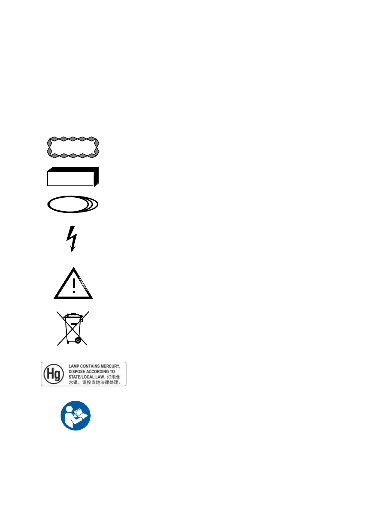
Caution advises of an avoidable condition that could cause minor
physical injury, or damage to equipment or data.
Warning advises of an avoidable condition that may allow or cause a
personal injury or the catastrophic destruction of equipment or data.
Danger advises of an avoidable condition that will cause serious or fatal
injury.
Dangerous Voltage. Indicates an avoidable dangerous high voltage
hazard.
This symbol on the equipment means that the operating instructions
should be consulted to assure safe operation.
This symbol indicates that waste electrical and electronic equipment
must not be disposed of as unsorted municipal waste and must be
collected separately. Please contact an authorized representative of the
manufacturer for information concerning the decommissioning of your
equipment
This product consists of devices that may contain mercury, which must
be recycled or disposed of in accordance with local, state, or country
laws. (Within this system, the backlight lamps in the monitor display
contain mercury.)
Follow instructions for use.
GE MEDICAL SYSTEMS Operator Manual
REV 22 DIRECTION 2259724-100
CHAPTER 2 SYMBOLS
Symbols used on this system and in its accompanying documents are
shown and explained in this section.
2-1 Special Notices
2-1
Page 26
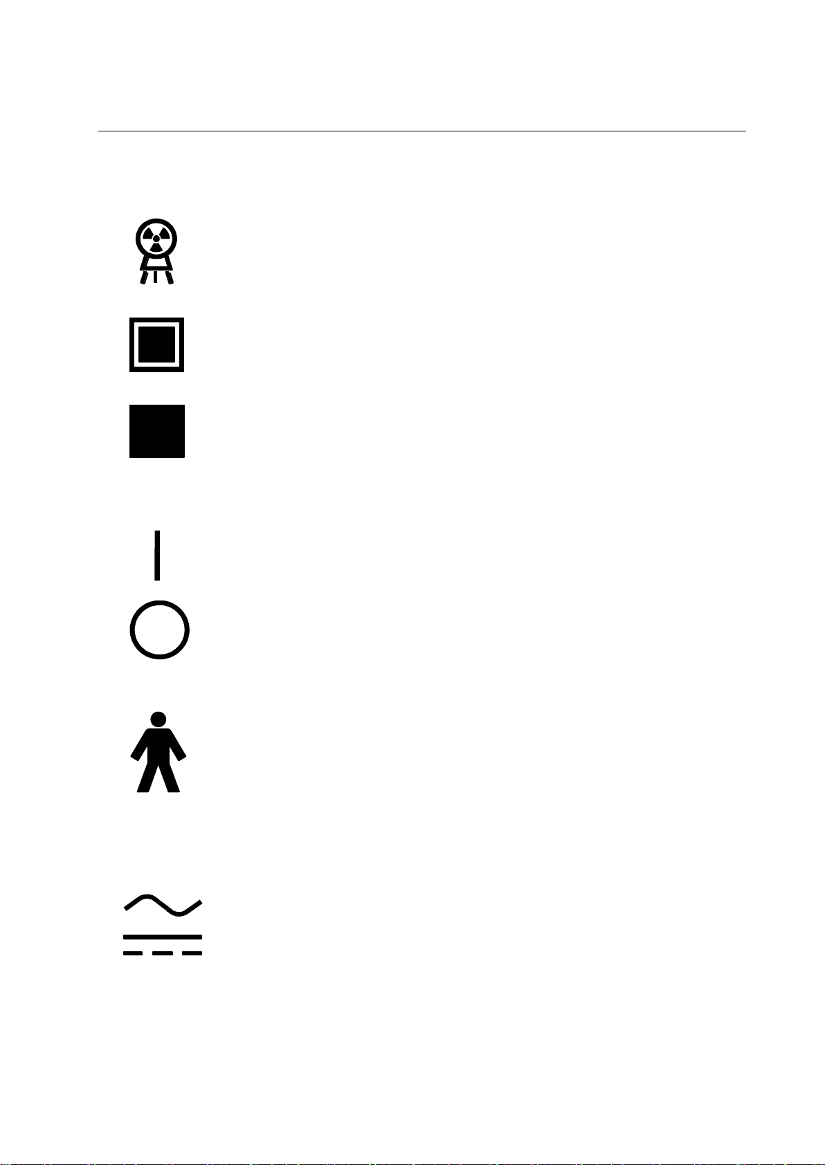
PROTEUS XR/a
Power ON switch or switch position that applies mains voltage. Indicated
connection to the mains for all mains switches or their positions. This
symbol is used in all cases where safety is involved.
Power OFF switch or switch positions that removes mains voltage.
Indicated disconnection from the mains for all mains switches or their
positions. This symbol is used in all cases where safety is involved.
Type B Equipment. Equipment providing a particular degree of protection
again electrical shock regarding leakage current and protective grounding
per IEC 601-1.
Alternating Current. Indicates equipment that is suitable for alternating
current only.
Direct Current. Indicates equipment that is suitable for direct current only.
X-ray emission. X-ray tube head is emitting X-rays. Take adequate
precautions to prevent the possibility of any persons carelessly,
unwisely, or unknowingly exposing themselves or others to radiation.
Identifies controls or indicators associated with the selection of a small
focal spot or the connection for the corresponding filament.
Identifies controls or indicators associated with the selection of a large
focal spot or the connection for the corresponding filament.
GE MEDICAL SYSTEMS Operator Manual
REV 22 DIRECTION 2259724-100
2-2 X-ray Tube
2-3 Power ON and OFF
2-4 Electrical Type
2-5 Electrical Current
2-2
Page 27
PROTEUS XR/a
Proteus XR/a Collimator
Eclipse Proteus Collimator
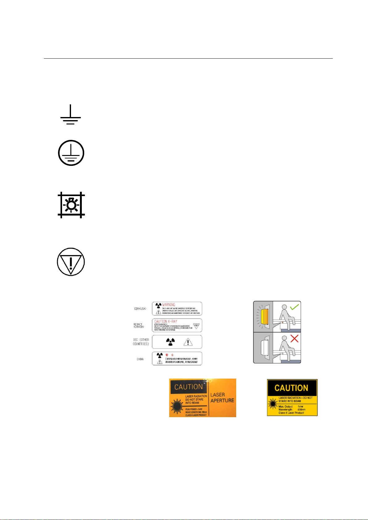
Functional Earth (ground) Terminal. Terminal directly connected to a point
of a measuring supply or control circuit or to a screening part which is
intended to be earthen for functional purposes.
Protective Earth (ground). Identifies any terminal that is intended for
connection of an external protective conductor to protect against
electrical shock in case of a fault.
Control for indicating radiation field by using light.
Immediately removes power from table.
Label for inhibition button
GE MEDICAL SYSTEMS Operator Manual
REV 22 DIRECTION 2259724-100
2-6 Ground
2-7 Proteus XR/a Collimator / Eclipse Proteus Collimator
2-8 Emergency Button
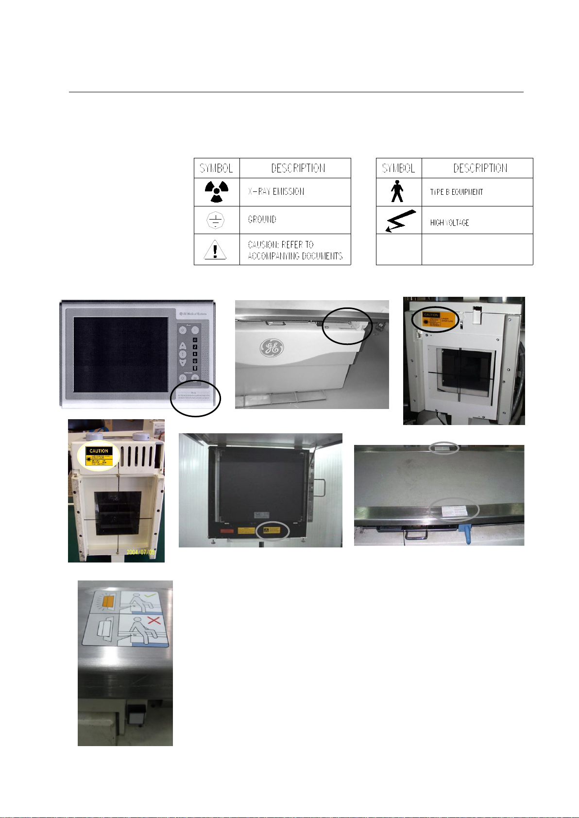
2-9 Warning Signs and Labels
Laser Warning
Note: If have, please confirm the collimator and wall stand you’ve chosen
by referring to the next chapter.
2-3
Page 28
PROTEUS XR/a
GE MEDICAL SYSTEMS Operator Manual
REV 22 DIRECTION 2259724-100
Table 2-1
MEANINGS OF PROTEUS XR/A SIGNS
Illustration 2-1
PROTEUS XR/A SYSTEM WARNING SIGNS LOCATION
2-4
Page 29
PROTEUS XR/a
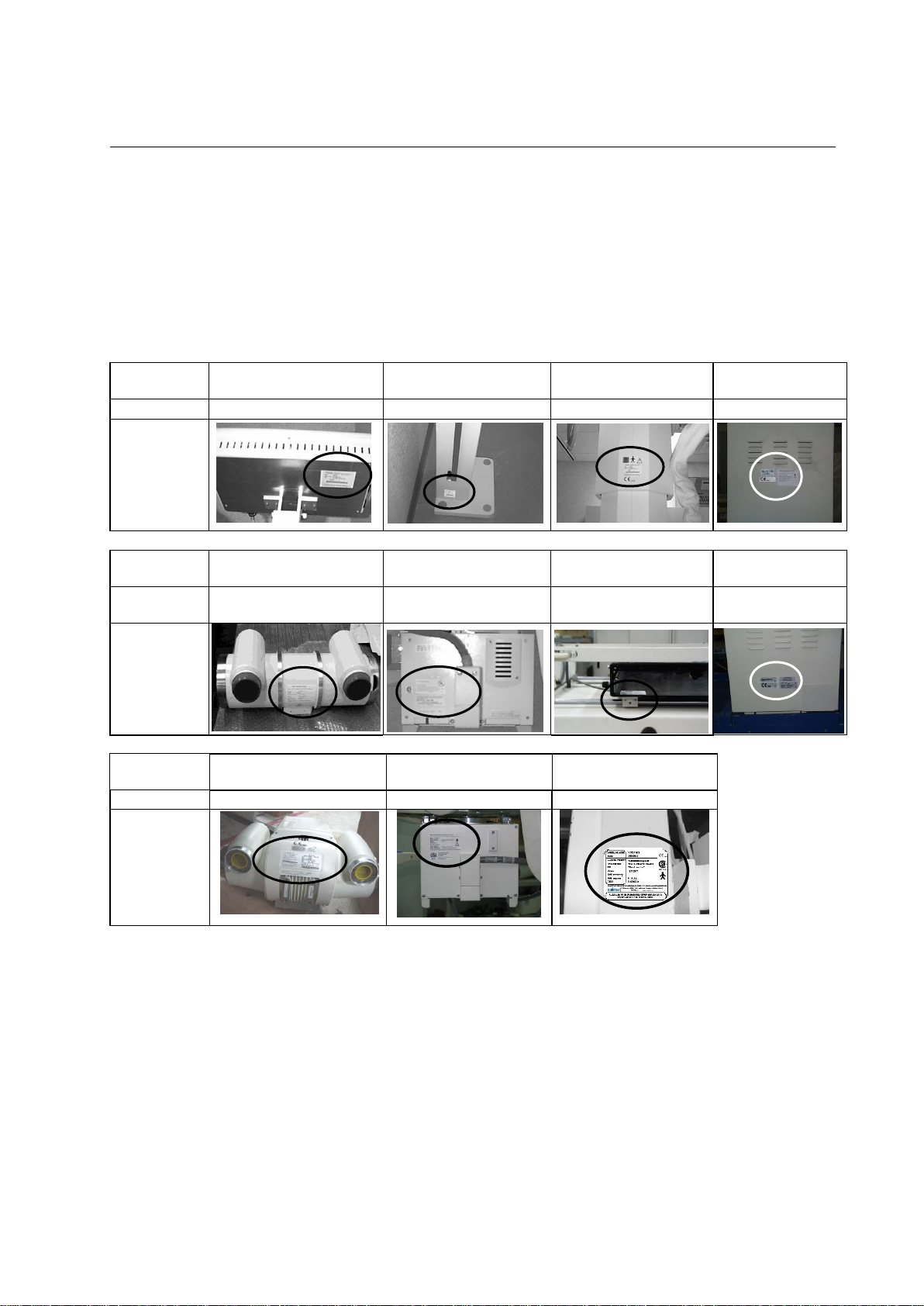
DESIGNATION
System console
Wall Stand
OTS radiographic
suspension (2/3 m)
Cabinet
PART NUMBER
2259976 or 5441870
600-0301
S3918MD/S3918K
2259973
LOCATION of
Name Plate
DESIGNATION
X-ray Tube (RAD-14)
Proteus XR/a
Automatic Collimator
Bucky (L/H)
Jedi Generator
PART NUMBER
2259981
2259298-54
2189553 or
5159516-1
2268970 or
2244165-2
LOCATION of
Name Plate
DESIGNATION
X-ray Tube (MX 100)
Eclipse Proteus
Collimator
SG120 Wall Stand
PART NUMBER
D2301R
2379827
2402562
LOCATION of
Name Plate
GE MEDICAL SYSTEMS Operator Manual
REV 22 DIRECTION 2259724-100
2-10 System Labelling
The labels for the Proteus XR/a system are found on the side panel of
the Proteus XR/a cabinet. This label includes the CE mark for the entire
system. See the following sketch.
For other name plate location, see table 2-2.
Table 2-2
PROTEUS XR/a SYSTEM IDENTIFICATION AND COMPLIANCE PLATES
2-5
Page 30

PROTEUS XR/a
GE MEDICAL SYSTEMS Operator Manual
REV 22 DIRECTION 2259724-100
This page intentionally left blank.
2-6
Page 31

PROTEUS XR/a
GE MEDICAL SYSTEMS Operator Manual
REV 22 DIRECTION 2259724-100
CHAPTER 3 SYSTEM DESCRIPTION
The Proteus XR/a X-ray System is a general radiographic system
designed for a wide ra-nge of table, wall stand, wheelchair, and stretcher
examinations. The system is especially suited for general-purpose
radiography in hospitals, clinics, and private practices.
Note: Please confirm the collimator you’ve chosen by referring to the
following contents.
Note: If have, please confirm the wall stand you’ve chosen by referring to
the following contents.
3-1 System Components/Features
The basic Proteus XR/a System consists of:
1 Generator Cabinet
32, 50 kW, 50 kHz High Frequency Generator
65, 80 kW, 50 kHz High Frequency Generator (optional)
2 System console
Color LCD Touch Screen
Floppy/USB disk support (only one option for default)
3 OverHead Tube Suspension (OTS)
Control Console
Receptor Selection
kV/mAs Adjustments
SID Display
Angle Display
4 Table (optional)
Elevating Table
Bucky
Fixed Grid Cassette Holder (optional)
Ion Chamber for AEC (optional)
5 Wall Stand (GPCP No.: 600-0301) (optional)
Bucky
Stationary Grid (optional)
Ion Chamber for AEC (optional)
6 SG120 Wall Stand (GPCP No.: 2402562) (optional)
Revolvable Bucky
Vibrating Grid (optional)
Ion Chamber for AEC (optional)
7 Proteus XR/a Collimator
Automatic
Manual (optional)
8 Eclipse Proteus Collimator
9 X-ray Tube
VARIAN Rad14 Tube, Part Number 2259981: High Speed -
0.6/1.2 Focal Spot (32, 50 kW systems)
GE MX100 Tube, Part Number D2301R: High Speed - 0.6/1.25
(1.3 IEC) Focal Spot (65, 80 kW systems)
3-1
Page 32

PROTEUS XR/a
1. System Console
7. X-ray Tube
2. Elevating Table
8. Proteus XR/a Collimator
3. Overhead Tube Suspension
9. Eclipse Proteus Collimator
4. Wall Stand (GPCP No.: 600-0301) (optional)
10. Tomography (optional)
5. SG120 Wall Stand (GPCP No.: 2402562) (optional)
11. Printer (optional)
1
2
3
4
6 7 8/9
WARNING
5
GE MEDICAL SYSTEMS Operator Manual
REV 22 DIRECTION 2259724-100
10 Tomolink (optional)
Tomolink System Console
Control Electronics Wall Box
Table/OTS Coupling Hardware
OTS Drive
11 Printer (optional)
ANY OPTIONAL AND REPLACED COMPONENTS SHOULD BE
COMPATIBLE WITH THE SYSTEM AND BE AUTHORIZED BY GE
COMPANY, OTHERWISE THEREOF THE LOSS OR DAMAGE IS
NOT THE RESPONSIBILITY OF GE COMPANY.
Note: Tabletop, PA bar, Lateral bar, Table Hand Grips, Compression Band
and Wall Stand receptor front panel are applied parts. These parts will
be handled by patients.
ILLUSTRATION 3-1
PROTEUS XR/A SYSTEM COMPONENTS
The Proteus XR/a System is divided into basic components:
3-2
Page 33

PROTEUS XR/a
6. Generator Cabinet
GE MEDICAL SYSTEMS Operator Manual
REV 22 DIRECTION 2259724-100
3-3
Page 34

PROTEUS XR/a
PRODUCT CATEGORY
PRODUCT DESCRIPTION
MODEL
NUMBER
RADIOGRAPHIC TABLE
PROTEUS TABLE
2259988
VERTICAL CASSETTE
HOLDER
WALL STAND
600-0301
SG120 TILTING / ROTATING
WALL STAND
2402562
BEAM LIMITING DEVICE
PROTEUS XR/A MANUAL
COLLIMATOR
2259989
PROTEUS XR/A AUTO
COLLIMATOR
2259298-54
ECLIPSE PROTEUS
COLLIMATOR
2379827
XRAY TUBE HOUSING
ASSEMBLY
RAD 14, 32/50KW
2259981
MX 100, 65/80KW
D2301R
XRAY CONTROL
SYSTEM CONSOLE
2259976 OR
5441870
HIGH VOLTAGE GENERATOR
JEDI 80R 1T
2268970
GE MEDICAL SYSTEMS Operator Manual
REV 22 DIRECTION 2259724-100
3-2 HHS Compliance Compatibilities
The purpose of this table is to provide users and installers, the ability to
verify that all the HHS Certified Components of this system are
compatible.
Purpose
Installers must indicate that the combination of installed HHS Certified
Components is compatible on Form F3382 provided in Direction 46013894, System Field-Test For HHS.
TABLE 3-1
PROTEUS XR/A SYSTEM HHS COMPLIANCE COMPATIBILITY LIST
3-4
Page 35

PROTEUS XR/a
CAUTION
WARNING
CAUTION
POWER
OFF
POWER
ON
POWER
ON/OFF
SYSTEM
INDICATOR
INCREASE
/DECREASE
EXPOSURE
CONTROL
GE MEDICAL SYSTEMS Operator Manual
REV 22 DIRECTION 2259724-100
CHAPTER 4 PROTEUS XR/A SYSTEM START UP AND SHUT
DOWN
Illustration 4-1
SYSTEM CONTROL PANEL
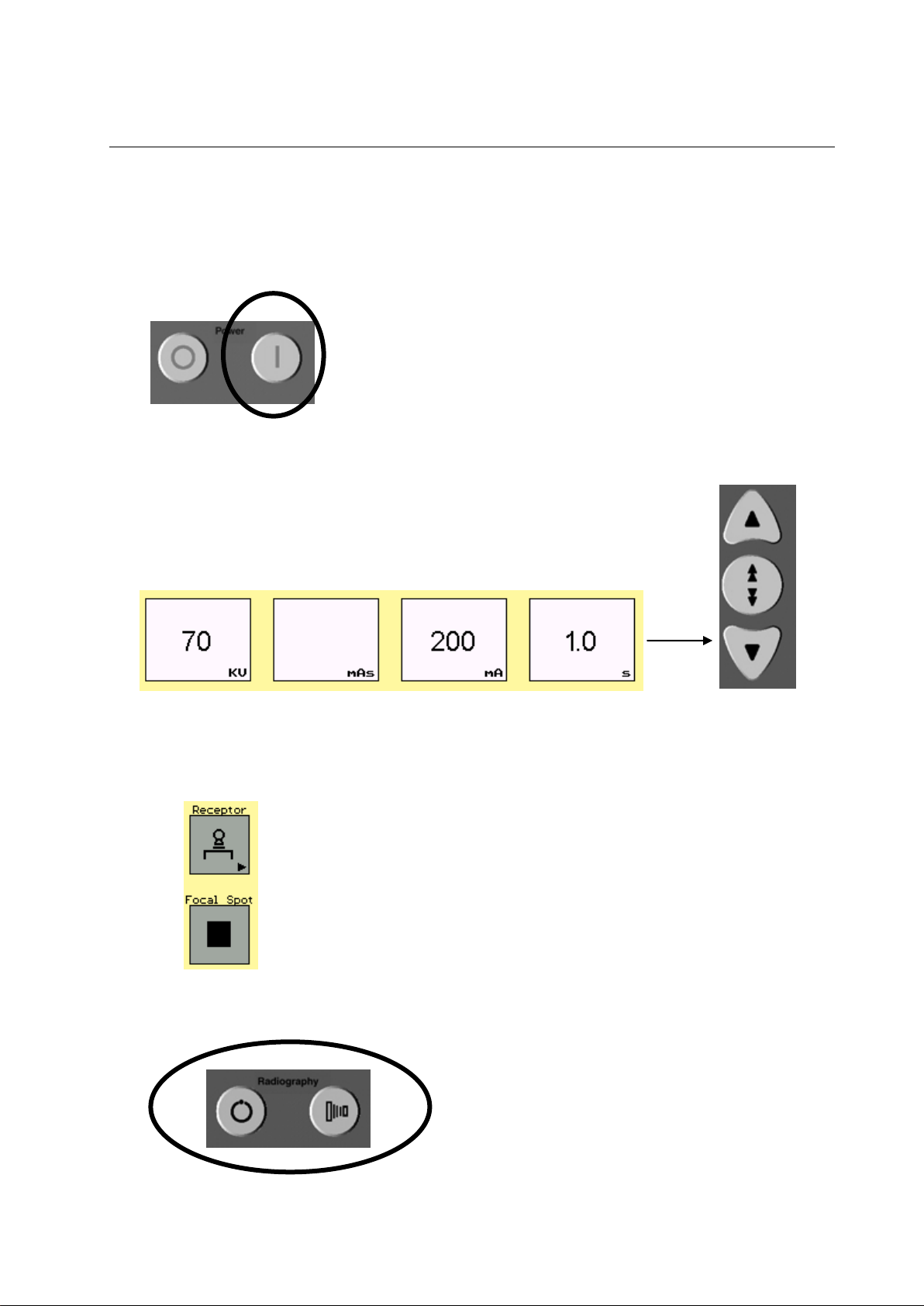
4-1 Turn the power on
Illustration 4-2
SYSTEM POWER ON/OFF
To turn ON the generator, press the “power on ” button located on the
right side of the control console.
4-2 Turn Power off
When the generator is on the color touch screen will appear.
Also on the status display area ( ) will light up indicating the system
power is on. All other equipment in the room will simultaneously turn
on.(Table, OTS, x-ray system equipment etc.)
To turn OFF the generator, press the “power off” located on the right side
of the control console. All other equipment in the room will turn off.
When the power is turned off, the color touch screen will disappear. Also
the indicator in the system display area will not be lit.
Do not turn the power ON and OFF quickly. Wait at least 30 seconds
between switching from ON / OFF and vice versa.
IN EMERGENCY, USE “EMERGENCY OFF” SWITCH LOCATED ON
THE WALL NEXT TO THE CONTROL CONSOLE.
Except in emergency, do not turn the generator off until the
“READY” indicator on the status display is extinguished. Turning off
the generator before this stage then will cause undue stress on the
X-ray tube.
4-1
Page 36

PROTEUS XR/a
TUBE OVER
HEAT
INDICATOR
SYSTEM
INHIBIT
INDICATOR
SYSTEM
POWER ON
INDICATOR
X-RAY ON
INDICATOR
GENERATOR
READY
INDICATOR
GE MEDICAL SYSTEMS Operator Manual
REV 22 DIRECTION 2259724-100
4-3 Daily Warm Up Procedures
A tube warm up is recommended every day before the system is used. A
tube warm-up should also be completed if the system is inactive for more
than 2 hours.
To maximize tube life, perform the following tube warm-up procedure:
1. The room should be free of a patient or personnel
2. Close collimator blades or block x-ray output.
3. Take 2 exposures (30 seconds apart) with the following technique
Parameters:
Table top receptor
Large focal spot
70 kV
200 mA at 1 sec
Illustration 4-3
System Status Display
4-4 System status display
Tube Over Heat Indicator: If the Tube Over Heat Indicator light appears, the system has
4. Once exposures are taken the system is ready for use.
The System Status Display is located on the control console under power
On/Off buttons. Refer to Illustration 4-1. Within this display, there are five
status indicators:
over heated. The system will not allow the user to take any exposures
until the tube is properly cooled down.
System Inhibit Indicator: If the System Inhibit Indicator light appears, the system is
indicating there is an error. This may indicate:
Examination room door is open (indicator will flash)
Various inhibition errors on the system (see Table 12-2)
Technique overload (the parameter which is over the limit will flash)
System Power On Indicator: This indicator light appears when the system is turned on
and stay on until the system is turned off.
Generator Ready Indicator: The Generator Ready Indicator appears during the prep for
X-ray exposure.
X-ray ON Indicator: The X-ray ON Indicator appears indicating the generator is
producing X-ray radiation.
4-2
Page 37

PROTEUS XR/a
TRIGGER
LEVEL I
LEVEL II
WARNING
EXPOSURE
PREP
WARNING
GE MEDICAL SYSTEMS Operator Manual
REV 22 DIRECTION 2259724-100
4-5 Radiography Control Key
ILLUSTRATION 4-4
HANDSWITCH
Make an Exposure (Handswitch)
Illustration 4-5
ANODE START UP/EXPOSE
Make an Exposure (System Console)
An exposure can be made using the handswitch that is connected to the
System Console, or by using the exposure keys on the System Console.
The handswitch is a three-position push button switch. Its three positions
are OFF, Prep and Expose. The handswitch is normally in the OFF
position. See Illustration 4-4.
Press the handswitch halfway to the Prep position for 1-1.5 seconds. This
prepares the X-ray tube for exposure. Then press the handswitch all the
way down to the Exposure position and hold until the exposure is
complete. A beep will sound notifying that the exposure is complete.
X-RAY EMISSION IS TERMINATED INSTANTLY WHEN YOU
RELEASE THE HANDSWITCH PUSHBUTTON.
On the lower right hand corner of the System Console under the system
status display is where the Prep and Exposure buttons are located. See
Illustration 4-1.
To make an exposure using the System Console, first press down and
hold the PREP button for 1-1.5 seconds. This prepares the X-ray tube for
exposure. Then press the EXPOSURE button down until the exposure is
complete. A buzzer will sound notifying that the exposure is complete.
Note: When select TOMO while make exposure, make sure to press ”PREP”
and “EXPOSURE” button during the whole exposure process, that
is, tube travel reverses at the sweep limit and returns to center in
the end.
IF THE SYSTEM IS EQUIPPED WITH A TUBE FAN, IT IS IMPORTANT
TO MAKE SURE THE FAN IS WORKING PROPERLY FOR HEAVY
LOAD. WHEN THE TUBE FAN STOPS, PLEASE CALL SERVICE AS
SOON AS POSSIBLE AND AVOID OVEREXPOSURE UNTIL THE
TUBE FAN IS WORKING NORMALLY. OTHERWISE THE TUBE MAY
BE OVERHEATED AND BROKEN.
4-3
Page 38

PROTEUS XR/a
GE MEDICAL SYSTEMS Operator Manual
REV 22 DIRECTION 2259724-100
This page intentionally left blank
4-4
Page 39

PROTEUS XR/a
WARNING
Group 1
Group 2
Group 3
Group 4
Group 5
GE MEDICAL SYSTEMS Operator Manual
REV 22 DIRECTION 2259724-100
CHAPTER 5 PROTEUS XR/A SYSTEM CONSOLE
5-1 Introduction
This section introduces you to the Operator Console Display. A standard
system screen is used as an example to acquaint you with the
arrangement of screen information.
Beside the ON/OFF, and status display buttons described in the previous
section, the console also has a prep/expose hand switch and prep
exposure buttons. The console also has an indicator lamp for x-ray
exposure. It is located on the status display bar.
When there is an x-ray exposure the yellow x-ray exposure indicator
lights and the console beeps. X-rays are produced when the x-ray
prep/exposure buttons or hand switch are pressed.
On the outside of the display screen are a set of up/down arrows. These
arrows are used to change the technique factors on the display screen.
These buttons will be explained in the technique section.
If the Operator Console System is designed with a USB port, one GE
qualified USB disk will be provided with the system for APR&AEC Backup
and Retrieve.
Note: Only the GE qualified USB disk is allowed to be used with the GE
Console System. It shall be ensured that this GE qualified USB disk
can only be used for its supposed purpose with the GE Console and
is not allowed for any other use.
NEVER LOAD NON-SYSTEM SOFTWARE ONTO THE SYSTEM
CONSOLE.
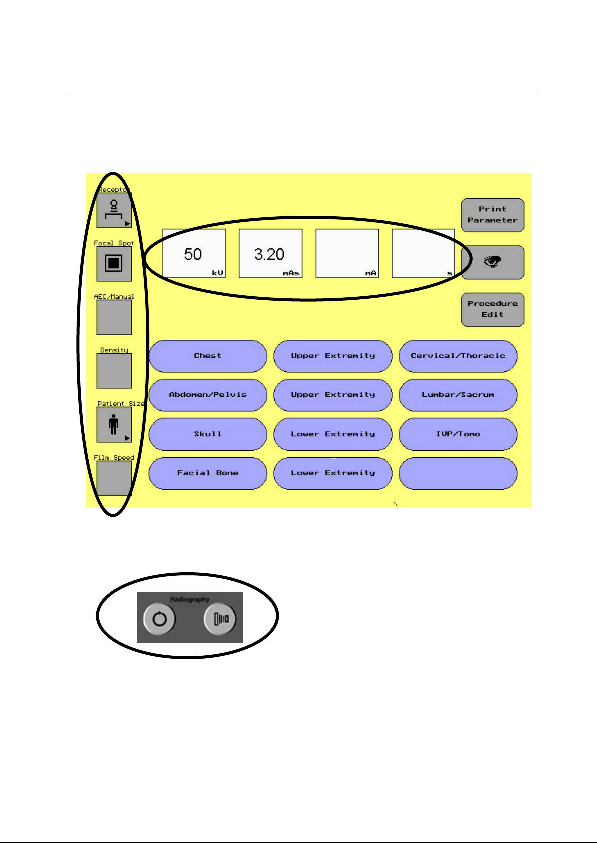
ILLUSTRATION 5-1
UNDERSTANDING THE DISPLAY
Group 1 Technique S
5-1
Page 40

PROTEUS XR/a
GE MEDICAL SYSTEMS Operator Manual
REV 22 DIRECTION 2259724-100
Group 1 Parameter selection Area, see 5-1-1
Group 2 Technique Selection Area, see 5-1-2
Group 3 Error Message Area, see 5-1-3
Group 4 Anatomical Programmer with Procedure Edit, see 5-2
Group 5 Print button and display button, see 5-3-3
This is the main Screen of the system console. This will appear when the
system is initially turned on.
5-2
Page 41

PROTEUS XR/a
1. Buttons with an arrow () in the lower right hand corner
symbolize there is a submenu to make other selections
from, e.g. change from Table Bucky, to Table top, Wall or
Tomography.
2. Toggle Button: The focal spot button is the only toggle
button on the display screen. When this button is selected
it will alternate between small and large focal spot.
GE MEDICAL SYSTEMS Operator Manual
REV 22 DIRECTION 2259724-100
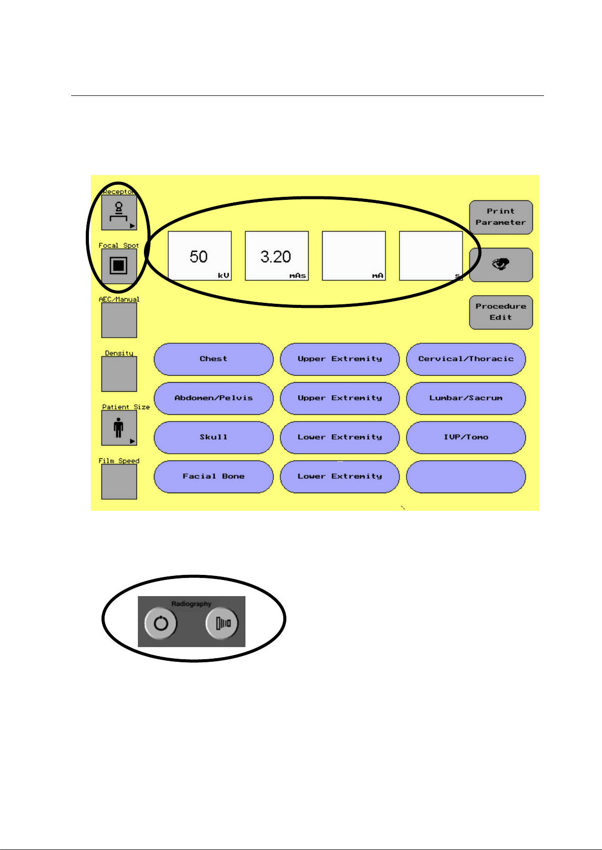
5-1-1 Group 1 Parameter Selection Area
ILLUSTRATION 5-2
PARAMETER SELECTION AREA
The parameter selection area of the display screen allows the
user to select different parameters depending on the
procedure being done.
In the parameter area of the display screen there are two
types of touch buttons:
Note: If collimation had been set on the collimator
first ,do not reset it by Receptor button, otherwise
the collimator would automatically close.
ILLUSTRATION 5-3
EXAMPLE OF PULL OUT SCREEN
To change a parameter that appears on the screen:
1. Touch the parameter of choice
A series of new selections will appear
2. Touch the new parameter
3. The new parameter will appear on the display
The following techniques are available with the order of how the
buttons will appear:
Receptor – Wall, Table, Table Top, Tomography
Focal Spot – Small Focal Spot, Large Focal Spot (Toggle Button)
AEC/Manual – Right - Left, Center, Right – Center – Left, Right,
Left, Right – Center, Left – Center, Manual (No AEC chambers
selected)
Density – + 2, +1, 0, -1, -2
Patient Size – Small, Medium, Large, Pediatric
Film Speed – 100/200, 400, 600/800
Note: If a site only uses one film screen combination, the field service
engineer can remove the button in the service software of the
console. Film screen combination is used for AEC only.
Selecting a button with an arrow ()
Note: If the system is purchased without the AEC option, the console will
not display AEC, Density or Film Screen.
5-3
Page 42

PROTEUS XR/a
Increase
Fast
Decrease
GE MEDICAL SYSTEMS Operator Manual
REV 22 DIRECTION 2259724-100
5-1-2 Group 2 Technique Selection
ILLUSTRATION 5-4
GROUP2 TECHNIQUE SELECTION
The technique selection area of the display screen allows the user to
select different technique factors depending on the procedures being
done.
There are four technique factors to choose from:
kV
mAs
mA
Sec
To change a technique use the up/down arrows on the right side of the
touch screen.
ILLUSTRATION 5-5
UP/DOWN ARROWS
Note: When the middle button is selected and you switch between
Note: In the technique area the user will always see a number displayed in
The up arrow allows the user to increase the technique factor selected by
a factor of 1 for kV or 1 renard step for mAs, mA or sec.
The down arrow allows the user to decrease the technique factor
selected by a factor of 1 kV or 1 renard step for mAs, mA or sec.
The middle button allows the user to change the function of the up/down
arrows from a 1 step increase/decrease for kV and sec. to a 10 step
increase/decrease.
technique factors (kV to mAs) the fast selection will deselect.
To set a technique
1. To set a technique touch the technique factor buttton of choice (kV,
mAs, mA, sec)
Once the button is selected, the button will turn black symbolizing
the button is active.
2. Use the up/down arrows to increase or decrease the technique factor
selected.
the kV button, but if the user selects mAs the numbers will
disappear in the mA and sec buttons. If the user selects mA or sec
the numbers will disappear in the mAs button.
5-4
Page 43

PROTEUS XR/a
GE MEDICAL SYSTEMS Operator Manual
REV 22 DIRECTION 2259724-100
5-1-3 Group 3 Error Message Screen
The Error message area of the display screen displays informational
messages to inform the user of system and subsystem operational
status. In this situation, all buttons will be inactive except the “OK”
button. The following messages will appear in the error message area.
Console Message: X-ray Room Door Open
Recommended Operator Action The door to the x-ray room is not
closed. The system will pro-hibit an
x-ray exposure until the door is
closed.
Console Message: Receptor Selection error
Recommended Operator Action This error will occur when the
selected receptor is not configured
on the Jedi generator configuration
menu.
Console Message: Error 30 Tube Spit error
Recommended Operator Action: The Proteus XR/a system has
detected a tube spit error. Press the
reset button and try the exposure
again. If error occurs again note the
error and call service.
Console Message: Error 40 Rotation error
Recommended Operator Action: The Proteus XR/a system has
detected a rotation error. Press the
reset button and try the exposure
again. If error occurs again note the
error and call service.
Console Message: Error 50 Heat (filament) error
Recommended Operator Action: The Proteus XR/a system has
detected a heat (filament) error.
Press the reset button and try the
exposure again. If error occurs
again note the error and call service.
Console Message: Error 60 Exposure error
Recommended Operator Action: The Proteus XR/a system has
detected a exposure error. Press the
reset button and try the exposure
again. If error occurs again note the
error and call service.
Console Message: Error 70 Power Supply error
Recommended Operator Action: The Proteus XR/a system has
detected a power supply error.
Press the reset button and try the
exposure again. If error occurs
again note the error and call service.
Console Message: Error 80 Hardware error
Recommended Operator Action: The Proteus XR/a system has
detected a hardware error. Press
5-5
Page 44

PROTEUS XR/a
GE MEDICAL SYSTEMS Operator Manual
REV 22 DIRECTION 2259724-100
the reset button and try the
exposure again. If error occurs
again note the error and call service.
Console Message: Error 90 Software error
Recommended Operator Action: The Proteus XR/a system has
detected a software error. Press the
reset button and try the exposure
again. If error occurs again note the
error and call service.
Console Message: Error 100 System Communication error
Recommended Operator Action: The Proteus XR/a system has
detected a system communi-cation
error. Press the reset button and try
the exposure again. If error occurs
again note the error and call service.
Console Message: Error 110 Tube/generator overheat error
Recommended Operator Action: The Proteus XR/a system has
detected a tube/generator overheat
error. Press the reset button and
wait until tube cooling down then try
the exposure again. If error occurs
again note the error and call service.
Console Message: Error 120 Application error
Recommended Operator Action: The Proteus XR/a system has
detected a application error. This
maybe due to a technique selection
error or when the exposure switch
was released before the exposure
was completed. Press the reset
button and change the technique or
make sure to hold down the
exposure switch untill the exopsure
is completed, then try the exposure
again. If error occurs again note the
error and call service.
5-6
Page 45

PROTEUS XR/a
GE MEDICAL SYSTEMS Operator Manual
REV 22 DIRECTION 2259724-100
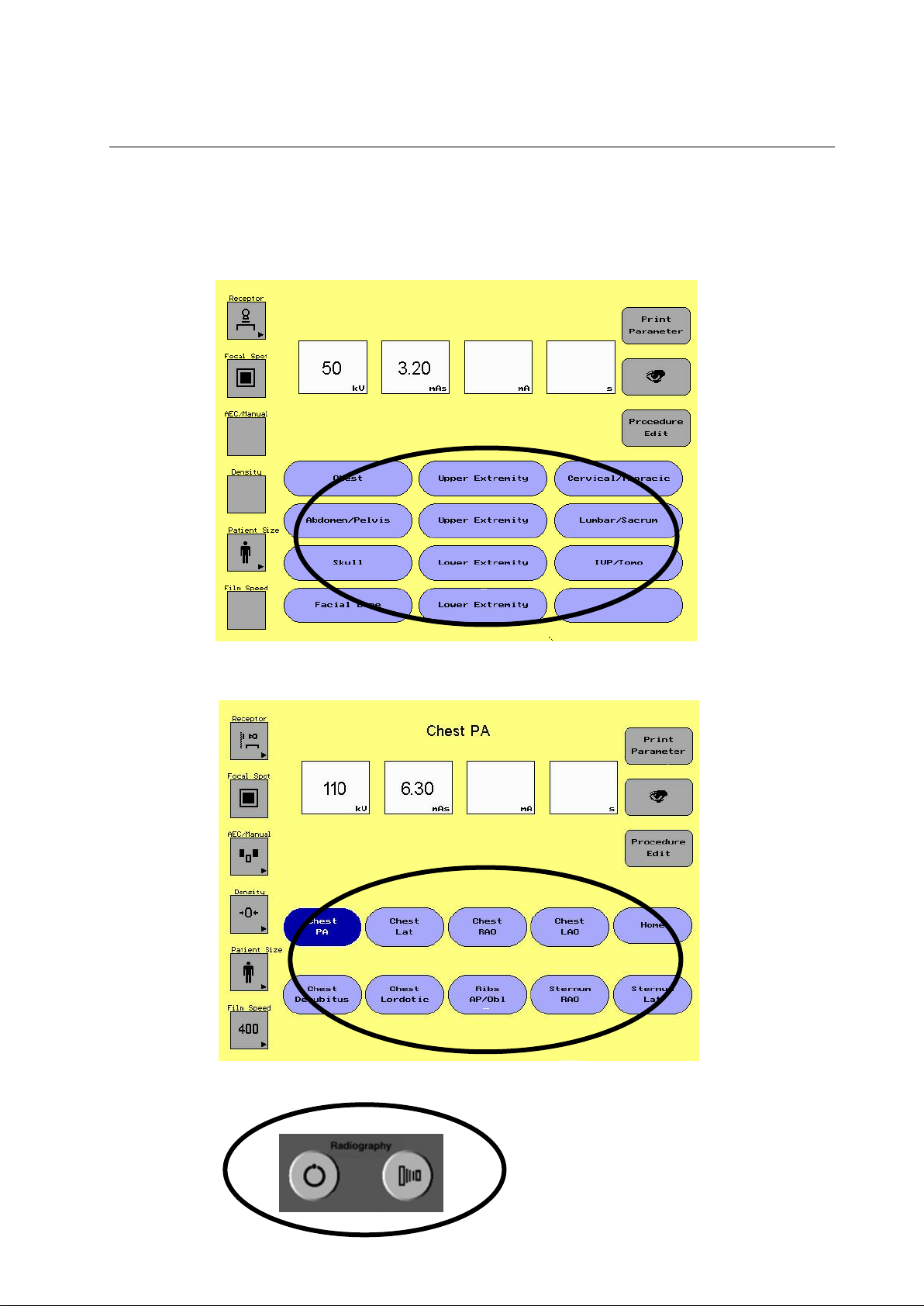
5-1-4 Group 4 Anatomical Programming (APR) with Procedure Edit
ILLUSTRATION 5-6
ANATOMICAL PROGRAMMING GROUP
The APR section of the display screen allows the user to select different
preset protocols depending on the procedure being done. There are 12
categories in which the user can select from. Under each of the 12
categories are 9 different procedure buttons and a home button. Each
button is a name of a procedure with preset parameters and techniques.
Once the user selects the category and procedure an exposure can be
taken
The 12 categories include:
Category Name Procedures in Category
1. Chest Chest, Ribs, Sternum
2. Upper Extremity Hand, Finger, Wrist, Forearm, Elbow
3. Cervical/Thoracic Cervical, Thoracic
4. Abdomen/Pelvis Abdomen, Pelvis, Hip
5. Upper Extremity Shoulder, Humerus, Sternoclavicular, AC
Joints, Clavicle, Scapula
6. Lumbar/Sacrum Lumbar, Sacrum, Coccyx
7. Skull Skull, Sinuses, TMJ
8. Lower Extremity Foot, Toes, Ankle, Tibia/Fibula, Oscalcis
9. IVP/Tomo KUB, IVP Tomo
10. Facial Bone Facial Bone, Nasal Bone, Zygomatic Arch,
Orbits
11. Lower Extremity Knee, Patella, Femur, Hip
12. Custom Area where user can put 9 procedures of choice.
To Use APR
1. Select a category
When the category is selected the procedure screen appears with
the first procedure in the category active. The active procedure will
be a darker shade of blue then the other procedures.
2. a. If this is the procedure, an display exposure may be taken.
b. If not select the procedure of choice, then take the exposure.
c. If a parameter or technique needs to be changed, change the
parameter or technique and then take the exposure.
Note: The protocols supplied with the system represent examples for
procedures commonly conducted in radiography. Based on the
needs of a particular practice, these protocols may be modified to
optimize factors such as image quality or dose reduction. Work
with your team of Radiologists, Medical Physicists and
Technologists to evaluate techniques that may reduce radiation
dose and provide adequate diagnostic information.
5-7
Page 46

PROTEUS XR/a
AREA(S)
SELECTED
APPLICATION
PATIENT
POSITIONING
None
AEC is off and the operator is
taking a manual exposure
No.2 Only
To control exposure for an area of
interest that is at center of the XRay field.
Position the area of
interest in the X-Ray
field center
No.1 Only
To control exposure for an area of
interest that is in the upper left
quadrant of the full sized
radiograph (Note 1)
Position the area of
interest in the upper
left quadrant of the XRay field
No.3 Only
To control exposure for an area of
interest that is in the upper right
quadrant of the full sized
radiograph (Note 1)
Position the area of
interest in the upper
right quadrant of the
X-Ray field
No.1 and No.3
together
To control exposure for two
symmetrical parts of the body
such as the lungs or kidneys
(Note 2)
Position the area of
interest to be aligned
with the No.1 and No.3
sensing areas.
To control exposure for two areas
of interest that are in the upper
left and center of the X-Ray field
Position the area of
interest to be aligned
with the No.1 and No.2
sensing areas.
To control exposure for two areas
of interest that are in the upper
right and center of the X-Ray field
Position the area of
interest to be aligned
with the No.2 and No.3
sensing areas.
All areas
together
To control exposure to allow the
average density of the whole
radiograph to approximate the
value of the preselected density.
Position the area of
interest within the
boundaries of the XRay field.
Note:
1. Areas No.1 and/or No.3 are to be used with a full size field
of 1012 (254mm305mm) or larger.
2. As area No.2 is not selected for this application, the
vertebral column should not affect the exposure,
providing that the patient is correctly positioned.
GE MEDICAL SYSTEMS Operator Manual
REV 22 DIRECTION 2259724-100
Note: An active procedure will be a dark shade of blue. Once a change is
made to a procedure the key will change back to the lighter shade
of blue. An exposure can be taken when a change is made, or any
procedure can be reselected.
5-1-5 AEC (Automatic Exposure Control) Operation – Optional Feature
The Proteus XR/a generator supports three field Ion Chambers in the
table or wall stand bucky/cassette tray for all radiographic applications.
AEC is an optional feature. The AEC function allows the operator to
select the automatic radiographic exposure control by corresponding field
area selection.
The following fields are supported by the system console:
TABLE 5-1
AEC AREA(S) SELECTED
AEC Density Compensations:
5-8
Page 47

PROTEUS XR/a
Scale
Density
Factor
Density correction
tolerance
2
59%more than A
A * 1.26 * 1.26
+/-10% * (A * 1.26* 1.26)
1
26%more than A
A * 1.26
+/-10% * (A * 1.26)
0
A 1 --
-1
20% less than A
A / 1.26
+/-10% * (A/1.26)
-2
37% less than A
A / 1.26 /1.26
+/-10% * (A/1.26/1.26)
GE MEDICAL SYSTEMS Operator Manual
REV 22 DIRECTION 2259724-100
The system console has five stations for density correction. Normal
density is automatically selected when AEC is on. The five stations of
density corrections are: +2, +1, 0, -1, -2.
See the table below for density change specifications.
5-9
Page 48

PROTEUS XR/a
GE MEDICAL SYSTEMS Operator Manual
REV 22 DIRECTION 2259724-100
5-2 Procedure Edit
Procedure Edit is a computer program with predefined x-ray procedure
parameters. This program is designed with pre-programmed protocols.
Each protocol loaded can be edited or new protocols may be stored.
5-2-1 Accessing Procedure Edit
1. From the main screen of the system console, select the Procedure
Edit button.
2. From any procedure menu screen on the system console, select the
Procedure Edit button.
Note: If the system console is configured with a floppy disk driver, to
make any changes to procedure edit, the procedure edit floppy disk
must be inserted into the disk drive.
Note: If the system console is configured with a USB Port, to make any
changes to procedure edit, please follow the below steps:
1. Turn the system off;
2. Plug in the APR&AEC USB disk into the USB port;
3. Follow the instructions to edit the procedure.
5-2-2 Getting Started
ILLUSTRATION 5-7
PROCEDURE EDIT SCREEN
It shall be ensured that the APR&AEC USB disk is not removed
when the system is on.
The procedure menu, shown in Illustration 5-7, is the Category screen of
procedure edit. This screen was selected from the main screen.
5-10
Page 49

PROTEUS XR/a
GE MEDICAL SYSTEMS Operator Manual
REV 22 DIRECTION 2259724-100
5-2-3 Category Screen
To Name or Change a name of a Category:
1. Touch the Name Cat button.
2. Touch the name of the category to be changed e.g. Chest
3. The screen will change to the keyboard screen.
4. Type in the new name of the procedure.
5. Touch the Done button to exit out of the keyboard.
6. Touch the Edit Done button to exit procedure edit.
Example of the keyboard screen:
ILLUSTRATION 5-8
EXAMPLE OF KEYBOARD SCREEN
Category Names can contain a combination of 18 characters or spaces.
The name appears between the brackets above the keyboard as it is
typed. The keyboard operation is similar to a typewriter.
Insert allows characters to be typed anywhere within the existing text.
Any characters to the right of the text will move over on character at a
time.
Delete Char removes the character to the left of the cursor.
Caps Lock switches text between small and capital letters.
Cancel lets you exit out of the keyboard screen without any changes.
This arrow button allows the user to skip down to the second
line of the text box.
Left, right, up and down arrows move the cursor in the direction of the
arrow.
Done saves the name and returns to the Procedure Edit screen.
Note: You can only input English characters.
If the user is in the typewriter screen and does not want to change the
name touch the cancel button. Touching the done button will erase the
name.
To go to a Procedure Screen from the Category Screen:
1. Touch the Category Button of the procedure.
2. The screen will change to the procedure screen.
3. Editing from the procedure screen can be done.
Note: To change any procedure, the procedure edit floppy disk or the
APR&AEC USB disk must be inserted. (Ensure that the system is off
when plug in the USB disk)
5-11
Page 50

PROTEUS XR/a
GE MEDICAL SYSTEMS Operator Manual
REV 22 DIRECTION 2259724-100
5-2-4 Procedure Screen
To Name or Change a name of a Procedure:
1. Touch the Name Proc button.
2. Touch the name of the procedure to be changed e.g. Chest PA
3. The screen will change to the keyboard screen.
4. Type in the new name of the procedure.
5. Touch the Done button to exit out of the keyboard.
6. Touch the Edit done button to exit procedure edit.
Illustration 5-9
PROCEDURE SCREEN
Procedure Names can contain a combination of 11 characters or spaces
per line. There are a total of 2 lines per procedure. The name appears
between the brackets above the keyboard as it is typed. The same
keyboard will appear as in the category screen.
To change parameters or technique in a procedure
1. Select procedure of choice (procedure button will be a darker shade
of blue).
2. Select the parameter/technique button to be changed.
3. Change the parameter/technique.
4. Select the save param button.
5. Touch the edit done button.
Note: If the changes to the procedure are the default parameters, touch
the default button then save param. The default parameters are the
protocol that appears on the screen when the user initially touches
a procedure.
5-12
Page 51

PROTEUS XR/a
GE MEDICAL SYSTEMS Operator Manual
REV 22 DIRECTION 2259724-100
5-2-5 Save/Retrieve
After entering procedures, it is a good practice to save them on the
diskette or the APR&AEC USB disk. The information may be transferred
in similar rooms to reduce the time spent making the next set of
procedures. A specially formatted disk is needed and supplied with each
system.
Save
Insert the specially formatted APR diskette into the floppy Disk Drive or
insert the APR&AEC USB disk into the USB port.
1. Touch SAVE BACKUP to copy all procedure editing information from
the current room onto the diskette or the APR&AEC USB disk. This
information will overwrite any data that was already on the diskette or
the APR&AEC USB disk.
Retrieve
Retrieve will read procedure editing information off the diskette or the
APR&AEC USB disk and store it in the system console computer
memory.
1. Insert the diskette containing a previously saved Procedure Edit
Database into the floppy disk drive, or, insert that APR&AEC USB
disk into the USB port (Ensure that the system is off when plug in the
USB disk).
2. Touch the RETRIEVE BACKUP to copy all procedure information to
the system.
3. Touch the EXIT button to exit this menu.
Note: Remove the APR disk after completing the APR revision.
5-13
Page 52

PROTEUS XR/a
1. 1
Select table top
AEC and density can’t be selected.
3 point & 2 point mode can be switched
2. 2
Select BUCKY & AEC (include
table and wall if BUCKY & AEC
is configured)
3 point without AEC, 3 point with AEC, 2
point without AEC, 2 point with AEC can
be switched
3. 3
Select TOMO
With AEC, without AEC can be switched
(only in 2 Point mode and displays value,
also it can be switch to 3 point mode)
4. 4
Receptor switch: from table top
to bucky, from bucky to table
top, from tomo to bucky, from
table top to tomo, from tomo to
table top
Table, Table Top, Wall (if have), Tomo (if
have) can be switched, and OTS receptor
also switch accordingly
Note: If select Table, Wall Stand or
Tomo, excluding Table top, as
the image receptor when taking
exposure either with or without
AEC, the cassette tray must be
inserted all the way into the Wall
Stand Bucky or Table Bucky. If
the cassette tray is not inserted
all the way into the Wall Stand
Bucky or Table Bucky, the
exposure will be prohibited
either with or without AEC.
When select Table top as the
image receptor, the cassette
should be placed on the table
top or the top of SG120 Wall
Stand Bucky (SG120 Wall Stand
Bucky is in Horizontal position,
Angulation is 90°, See
illustration 9-2) while not be
inserted into the Bucky when
taking exposure. And the
exposure will be made in Manual
mode.
Note: For SG120 Wall Stand, when
performing exposure operation
with the cassette placed on the
top of the Bucky (Bucky is in
horizontal position, Angulation
is 90°, see illustration 9-2), while
not be inserted into the Bucky,
the image receptor should be
selected to be “table top” on
System Console. And the
Exposure will be made in
Manual mode.
5. 5
Mode switch
2 point and 3 point can be switched
GE MEDICAL SYSTEMS Operator Manual
REV 22 DIRECTION 2259724-100
5-3 Application
Introduce the detailed operating on Proteus XR/a system.
5-3-1 Technique Selection
5-14
Page 53

PROTEUS XR/a
1.
Select kV, press quick
up/down key
kV button is selected and quick change
mark can be displayed.
2.
Select kV: press up or down
key
kV value can be changed between 40-150
quickly or slowly, if the kV is over
limitation, this button will blink , kV on
OTS also change accordingly
3.
Select mAs
If in 3 point mode, it will switch to 2 point
mode & mAs button is selected
4.
mAs: press up or down key
mAs value can be changed between 0.5630, if mAs is over limitation, this button
will blink , mAs on OTS also change
accordingly
5.
Select mA
If in 2 point mode, switch to 3 point mode
& mA button is selected( using tomo: it
can’t be selected)
6.
Select mA: press up or down
key
mA value can be changed between 101000(According to System Capacity), if
mA is over limitation, this button will blink ,
mAs on OTS also change accordingly
7.
Select s: press quick up/down
key
If in 2 point mode, switch to 3 point mode
and s button is selected and quick change
mark can be displayed (using tomo: it
can’t be selected)
8.
Select s: press up or down key
s value can be changed between 0.001-
6.3s quickly or slowly, if the value is over
limitation, this button will blink , mAs on
OTS also change accordingly
9.
Select Focal Spot
Focal Spot can be toggled
10.
Select density (if in AEC mode)
Density can be switched
11.
Select film speed (if configured
by FE)
Film speed can be switched
12.
Select patient size
Patient size can be switched
GE MEDICAL SYSTEMS Operator Manual
REV 22 DIRECTION 2259724-100
5-3-2 Parameter Change
5-15
Page 54

PROTEUS XR/a
1.
For AUTO collimator configuration, when collimator is in AUTOMATIC
mode, the impact from FOV, SID and tube angle is considered during Dose
and DAP calculation.
2.
For AUTO collimator configuration, when collimator is in MANUAL mode,
the impact from tube angle is ignored on DAP calculation.
3.
For MANUAL collimator configuration, only dose calculation is printed
and DAP calculation is not printed.
4.
For table top mode, only print Dose value @100cm SID.
1.
Prepare & exposure button
Press and hold prep button for 1-1.5s,
then press exposure button down until
the exposure is complete.
After exposure, the actual exposure
parameter will blink display several
seconds, then return to normal condition.
2.
Error
If there is some error, the error code will
be displayed and quit the exposure.
3.
If with a printer, press print
button
The printer will print patient ID, date and
last set parameter: kV, mAs (if in 2 point
GE MEDICAL SYSTEMS Operator Manual
REV 22 DIRECTION 2259724-100
5-3-3 Dose/DAP Indication
The Dose/DAP value is predicted by calculation. They are displayed on the image viewer for each
exposure. The Dose value is calculated at the position of patient entrance.
Block diagram for Dose/DAP calculation:
The nominal Dose is calculated at the calibrated distance, based on exposure techniques, such as mAs,
kVp and additional filtration. The final patient entrance dose is got by correcting with SID and tube angle
and the preset patient thickness.
DAP is got by multiplying Patient entrance dose and the image area at that distance.
Increase/decrease of the kVp, mAs, will lead to increase/decrease of Dose and DAP
Increase/decrease of the SID only, will lead to decrease/increase of Dose and DAP
Increase/decrease of the FOV only, will lead to increase/decrease of DAP, but Dose will not change.
Dose and DAP calculation:
5-3-4 Taking Exposure
5-16
Page 55

PROTEUS XR/a
mode) or kV, mA, s (in 3 point mode) and
exposure parameter: include: kV, mAs,
mA, s , filmsize and SID
4.
Press display button
The console will redisplay the last
exposure parameter: kV, mAs, mA, s for
15s, and press any button will return to
previous interface. If no exposure has
been done: it will display no exposure.
1.
System error Led
If there is any system error, this Led will
be on.
2.
Thermal error Led
If tube temperature is over limitation, this
Led will be on.
3.
Error message
When any error occurs, console will
display some error message and error
code: technique error, parameter error,
AEC error, rotor thermal error, inverter
thermal error, tank thermal error, Door
Open in exposure.
4.
PREP Led
Press and hold PREP button, the PREP
lamp will be on.
5.
Exposure Led
During X-ray emission, this lamp will be
on.
6.
Buzzer
During X-ray emission, it will be on.
7.
Turn auto/manual switch
Manual lamp on or off
8.
Table in PBL: when table in
center, SID in detent, Cassette
in place (if have tray selected)
Exposure ready is on, or exposure holder
is on
9.
WALL in PBL: when wall SID
in detent, Cassette in place
Exposure ready is on, or exposure holder
is on
10.
TOMO in PBL: when table in
center, SID in detent Cassette
in place (if have tray selected)
Exposure ready is on, or exposure holder
is on
11.
IN manual
Exposure ready is on, exposure holder is
off
1.
Press any APR button on main
screen
Enter the sub-APR interface and the
parameter display will not change
2.
Press home in any sub-APR
interface
Go back to the upper interface
3.
Press sub-APR button
The button will be selected and the
parameter displayed will change
accordingly.
4.
Insert the APR disk, then press
procedure edit button in main
screen.
Enter main screen edit interface, in this
screen, the parameter or technique can’t
be changed or selected.
5.
Press name cat button and
then press any APR button
Enter the name edit interface and edit the
APR name (only in English)
6.
Press Save/Retrieve button
Enter save & retrieve backup interface
7.
In save & retrieve interface:
press save button
Save the APR name to the floppy disk or
the APR&AEC USB disk
8.
In save & retrieve interface:
press retrieve button
If the floppy disk or the APR&AEC USB
disk has the relative file, it restores the file
GE MEDICAL SYSTEMS Operator Manual
REV 22 DIRECTION 2259724-100
5-3-5 Console Indicator
5-3-6 APR
5-17
Page 56

PROTEUS XR/a
to system or it displays error
9.
In save & retrieve interface:
press exit button
Return to the main screen edit interface
10.
In edit interface : Press edit
done button
Save the category name to the system
and return to the main screen interface
11.
In sub-APR interface: press
procedure edit button
Enter the sub-APR procedure edit
interface
12.
Press name proc and any subAPR name
Enter the name edit interface and edit the
name (only in English)
Press edit done button to save the
procedure name to the system and return
to the upper interface.
* Press home button will also return to
upper interface, but it will not save the
new procedure name.
13.
Insert the specific floppy disk
or the APR&AEC USB disk
and Press the save param
button
Save the parameter to the hard disk
14.
Press the default button
Save the receptor and patient size as the
default entrance of the relative sub-APR
15.
Press edit done button
Save the procedure name to the system
and return to the upper interface.
16.
If error occurrence
Display error message and reset button,
Only reset button is active in this state,
dispose the error and press reset button
to return.
GE MEDICAL SYSTEMS Operator Manual
REV 22 DIRECTION 2259724-100
5-18
Page 57

PROTEUS XR/a
WARNING
WARNING
WARNING
WARNING
WARNING
WARNING
WARNING
GE MEDICAL SYSTEMS Operator Manual
REV 22 DIRECTION 2259724-100
CHAPTER 6 PROTEUS XR/A TABLE COMPONENTS
6-1 Safe Operation Precautions
6-1-1 General
THE TABLE MUST BE USED ONLY BY QUALIFIED PERSONNEL
AND ONLY AFTER TRAINING IN THE SPECIFICS OF PROTEUS XR/A
TABLE OPERATIONS.
IT IS THE RESPONSIBILITY OF THE OPERATOR TO ENSURE THE
SAFETY OF THE PATIENT WHILE THE TABLE IS IN OPERATION BY
VISUAL OBSERVATION, PROPER PATIENT POSITIONING, AND USE
OF THE PROTECTIVE DEVICES PROVIDED.
THOROUGHLY CHECK THAT THERE IS NO INTERFERENCE OR
POSSIBILITY OF COLLISION BETWEEN THE PATIENT AND OTHER
EQUIPMENT.
6-1-2 Patient Positioning Precaution
ALWAYS BE ALERT TO PATIENT SAFETY CONCERNS:
NEVER LEAVE THE PATIENT UNATTENDED. AN UNATTENDED
PATIENT COULD FALL FROM THE TABLE, ACTIVATE A MOTION
CONTROL, OR CAUSE OTHER UNINTENDED PROBLEMS THAT
COULD BE HAZARDOUS.
CAREFULLY MONITOR ALL EQUIPMENT MOTIONS TO PREVENT
COLLISIONS.
ASSIST PATIENT ON AND OFF THE TABLE.
DURING TABLE TOP PROCEDURES ENSURE THAT THE PATIENT’S
HEAD, HANDS AND FEET ARE COMPLETELY WITHIN THE TABLE
TOP AREA. IF ANY PORTION OF THE PATIENT’S BODY EXTENDS
OVER THE EDGE OF THE TABLE TOP AREA SERIOUS INJURY MAY
RESULT.
THE MAXIMUM SUPPORTED WEIGHT WITH THE TABLE TOP
FULLY EXTENDED TOWARD THE HEAD OR FOOT END OF THE
TABLE IS 220 KG (484 LB), PROVIDED THE PATIENT IS FULLY
PROSTRATE. EXCEEDING THIS LIMIT MAY CAUSE EQUIPMENT
DAMAGE OR INJURY TO THE PATIENT.
MAKE SURE THAT PATIENT CONNECTED LINES, TUBES, ETC. ARE
LONG ENOUGH TO ALLOW FULL TRAVEL OF THE SYSTEM AND
WILL NOT BECOME PINCHED OR PULLED.
6-1
Page 58

PROTEUS XR/a
WARNING
WARNING
WARNING
WARNING
GE MEDICAL SYSTEMS Operator Manual
REV 22 DIRECTION 2259724-100
6-1-3 Table Top Motion
WHEN THE POWER TO THE TABLE IS CUT, THE TABLE TOP CAN
MOVE FREELY (LONGITUDINAL). TO AVOID INJURIES, MONITOR
THE TABLE TOP MOVEMENT.
PRIOR TO RAISING OR LOWERING THE TABLE TOP, ENSURE
THERE ARE NO OBSTRUCTIONS PRESENT ABOVE OR BELOW.
(SEE 6-1)
BEFORE THE PATIENT GETS UP ONTO OR DOWN OFF OF THE
TABLE TOP ALWAYS PRESS THE TABLE INHIBITION BUTTON TO
BLOCK THE CONTROL PEDAL FUNCTIONS MOMENTARILY, AND
THEREFORE AVOID INJURIES TO THE PATIENT OR DAMAGE TO
THE EQUIPMENT IF A CONTROL PEDAL IS ACCIDENTALLY
STEPPED ON.
6-1-4 HAND GRIPS
ALWAYS USE HAND GRIPS TO AVOID INJURY TO FINGERS AND
HANDS. THE PATIENT’S HANDS MUST BE KEPT AWAY FROM
TABLE TOP EDGES AT ALL TIMES.
6-2
Page 59

PROTEUS XR/a
GE MEDICAL SYSTEMS Operator Manual
REV 22 DIRECTION 2259724-100
6-2 Introduction
This section provides a general description for the Proteus XR/a table.
ILLUSTRATION 6-1
PROTEUS XR/A TABLE
1 Table Top
2 Table Base
3 Foot Pedals (on both side)
4 Cassette Tray
5 Bucky Film Cabinet Motion
6 Bucky Film Cabinet
7 Table Elevating Motion
8 Maximum Table Top Height (800mm)
9 Table top motion
10 Emergency stop
11 Table inhibition button
The Proteus XR/a Table is a radiographic positioner composed of:
- Table top.
The table top is made of foam. Its dimensions are 2250mm in length
and 880mm in width. Its filtration is less than 1.1 mm of aluminum at
100 KV.
The table top can be moved longitudinally and transversely for easy
patient positioning. Even when it is fully extended horizontally it can
support a prostrate patient weighing up to 220 kg (484 lbs.), in
accordance with Standard UL2601.
- Elevating Base.
The elevating base raises the table top to a maximum height of 800
mm (31.5”) and lowers it to a minimum height of 550 mm (21.6”).
The table power supply and electronics are located in the table base.
6-3
Page 60

PROTEUS XR/a
The Proteus XR/a Table is equipped with an emergency stop switches
located on the left and right side of the table. (See Illustration 6-1)
In the event of an emergency, press the emergency stop in with force.
When normal conditions are confirmed, turn the button clockwise so the
table can be powered up.
GE MEDICAL SYSTEMS Operator Manual
REV 22 DIRECTION 2259724-100
- Foot Pedals.
The control pedals are used to raise and lower the table top and to
free the table top for longitudinal and transverse positioning.
- Bucky Assembly.
The Bucky assembly is mounted on a carriage beneath the table top. It
contains a Manual Cassette Tray which accepts all standard sizes of
cassette ranging from130 x 180 mm to 350 x 430 mm (5 x 7”to 14 x
17”).
An ionization chamber can be located beneath the Bucky grid to
implement automatic exposure control. This is a optional component.
- Telescopic Covers.
These covers are assembled in two levels. Their purpose is to cover
the table power supply, and the electronic and mechanical
components located in the table base. This is essential when the table
top is raised or lowered.
- Hand Grips.
Two hand grips are included with the Proteus XR/a. These serve to
maintain the patients’ hands away from the table top edges and to give
patients a feeling of security. The grips are not intended to support the
weight of patients. For safety reasons the patient handgrips must be
used during all examinations. The grips slide onto the side rails of the
table top. They can be locked in place in any position along the side
rails with the thumbscrews.
- Table Inhibition Buttons.
Two Table Inhibition buttons are located on both front and back table
base. They are used to inhibit the table up-down and table top
movement.
- Emergency Buttons.
Two emergency buttons are located on both left and right side of the
table. These buttons are used to remove power from the table in an
emergency.
6-3 TABLE OPERATION
6-3-1Emergency Stop
6-3-2 Raising and Lowering the Table Top
To raise and lower the table, press the foot pedal two consecutive times.
This will activate the foot pedal switches. (See Illustration 6-1.)
Raising the Table top
To raise the table, press the control pedal two consecutive times and
hold down until the desired height is reached.
6-4
Page 61

PROTEUS XR/a
WARNING
CAUTION
CAUTION
WARNING
GE MEDICAL SYSTEMS Operator Manual
REV 22 DIRECTION 2259724-100
Lowering the Table top
To lower the table, press the control pedal two consecutive times and
hold down until the desired height is reached.
THE TABLETOP STOPS AUTOMATICALLY WHEN IT REACHES
MAXIMUM HEIGHT (800 MM), MINIMUM HEIGHT (550 MM). THE
TABLETOP WILL STOP WHEN THE OPERATOR TAKES HIS/HER
FOOT OFF THE PEDAL.
The Proteus XR/a Table is equipped with a collision detection system. If
contact is made between the tabletop and a foreign object such as a
stool while lowering the tabletop, the requested motion will automatically
stop until the collision condition is removed. This is accomplished by
either clearing the foreign object from the tabletop movement path or by
requesting the reverse movement of the tabletop.
To avoid jamming, do not put your foot right under the table outer
cover when table is driven down to the lower limit.
DO NOT TRY TO RAISE OR LOWER THE TABLE BY MEANS OF
THE CONTROL PEDAL WHILE THE TABLE AND XT SUSPENSION
ARE CONNECTED BY A TOMO-LINK UNLESS XT LOCKS ARE
RELEASED, OTHERWISE, THE TOMO-LINK MAY BE DAMAGED.
REFER TO DIRECTION 2122884-100.
6-3-3 Inhibition Button for Table Elevation or Table Top movement
To prevent the table elevation or Table top movement, presses down the
inhibition button. This button will simultaneously light symbolizing and the
table functions are locked.
When patients are getting on and off the table, to prevent possible
falling of the patients from the Table, press down the inhibition
button to prohibit the Table Elevation and Tabletop movement.
6-3-4 Positioning the Table top Longitudinally and Transversely
To position longitudinally and transversely with respect to the X-ray tube,
press either outer control pedal two consecutive times. Then you can
move the Tabletop to the desired position manually.
To lock the Tabletop, release the control pedal.
6-5
Page 62

PROTEUS XR/a
WARNING
10
11
9 4 1
2
3
8
7
5
6
WARNING
GE MEDICAL SYSTEMS Operator Manual
REV 22 DIRECTION 2259724-100
WHEN MOVING THE TABLE TOP, CARE SHOULD BE TAKEN
WHERE THE OPERATOR’S AND PATIENT’S FINGERS ARE
PLACED. DO NOT ATTEMPT TO MOVE THE TABLETOP WITHOUT
USING THE CONTROL PEDALS TO RELEASE THE LONGITUDINAL
AND TRANSVERSE MOVEMENT LOCKS.
TO AVOID INJURY TO FINGERS AND HANDS OF PATIENT AND
OPERATOR CAUSED BY TABLE TOP MOVEMENT, HANDS MUST
BE KEPT AWAY FROM TABLE TOP EDGES AT ALL TIMES.
6-4 Cassette Tray Operation
The Bucky is equipped with a cassette tray which is located in the Bucky
tray slot. It accepts cassette sizes ranging from 12.70cmx17.78cm (5”x7”)
through 14”x17” (35.56cmx43.18cm).
6-4-1 Introduction
See Illustration 6-2 and Table 6-1.
ILLUSTRATION 6-2
CASSETTE TRAY (TABLE OR VERTICAL WALL STAND) OPERATOR CONTROLS
6-6
Page 63

PROTEUS XR/a
Item
Title
Type
Description
1
Cassette Grips
Control
Grips the cassette in transverse position.
Front grip controls rear grip.
2
Tray Handle
Control
Provides ability to remove or insert tray
into Film Cabinet.
3
Alignment Notch
Indicator
Indicates the center of film for alignment
with collimator centering light.
4
Grip Lock
Control
Locks cassette into transverse grips.
5
Carrier frames
Control
Aid in centering the cassette in a vertical
Bucky.
6
Stopper
Control
Push the stopper to move the Carrier
frame
7
Centering Scale
Indicator
Centers the cassette right or left through
visual alignment.
8
Tray Stop Release
Control
Release tray stop so that you can remove
the tray from the Bucky
9
Cassette In Place
Switch
Control
Provides access for cassette removal.
10
Amphenol
Connector
Commu
nicator
Deliver message from cassette size
sensor.
11
Cassette Size
Sensor
General
Auto detect cassette size.
A
BCD
GE MEDICAL SYSTEMS Operator Manual
REV 22 DIRECTION 2259724-100
TABLE 6-1
CASSETTE TRAY OPERATOR CONTROLS AND INDICATORS
6-4-2 Cassette Loading
ILLUSTRATION 6-3
LOADING CASSETTES INTO CASSETTE TRAY
6-7
Page 64

PROTEUS XR/a
GE MEDICAL SYSTEMS Operator Manual
REV 22 DIRECTION 2259724-100
For Table cassette loading, move Table top fully backwards.
1. To insert a cassette, pull the tray out of the Bucky to the tray stop.
2. Lift the clamping lock handle to unlock it (A).
3. Slide the clamping lock apart to insert a cassette between the clamps
(B).
4. Place the cassette in the tray and center the cassette with either the
centring scale or the centering notches in the clamp (C).
5. Push the clamping lock against the cassette(C).
6. Press down on the clamping lock handle (D). Push tray into receptor.
Note: To prevent damage to the cassette clamps locking assembly always
close it prior to inserting (pushing) the cassette tray into the Bucky.
Note: Normally the cassette tray does not have to be completely removed
from the Bucky in order to load a cassette. Cassette may be
inserted in the tray by pulling the tray until movement is stopped by
the catch on the lower rear of the tray.
However, if it is desired to remove the tray from the Bucky, pull the
tray out until it is stopped by the catch, then press the catch against
the tray bottom and hold it while sliding the tray out.
Note: If select Table, not Table top, as the image receptor on the System
6-4-3 Cassette Removal
6-4-4 Alignment
Console (refer to section “5-3-1 Technique Selection” in Chapter 5)
when taking exposure either with or without AEC, the cassette tray
must be inserted all the way into the Table Bucky. If the cassette
tray is not inserted all the way into the Table Bucky, the exposure
will be prohibited either with or without AEC.
To remove a cassette from the manual cassette tray, pull the tray out fully
by its handle. Pull up on the tightening lever and pull it back away from
the cassette. The cassette is now free to be removed.
It is important that the X-ray tube unit be transversely centered accurately
with the center of the Bucky. Density cut off at the edges of the film and
appearances of grid patterns indicate inaccurate transverse alignment.
With an anti-diffusion grid vertical alignment is not critical, and tilted tube
techniques may be used without undue cut-off.
The center of the cassette tray handle is marked to indicate the
longitudinal center of the Bucky to the X-ray beam. Depending on the
position of the tabletop, the Bucky handle may need to be pulled out to
allow the collimator light to shine on it.
6-8
Page 65

PROTEUS XR/a
7-1
Stationary
Rail
OTS Console
Bridge
Telescopic
Column
GE MEDICAL SYSTEMS Operator Manual
REV 22 DIRECTION 2259724-100
CHAPTER 7 PROTEUS XR/A OVERHEAD TUBE SUSPENSION
7-1 Introduction
The Overhead Tube Suspension (OTS) is the positioning device that supports the
X-ray tube and OTS Console.
Each suspension provides convenient movement and accurate positioning of the
equipment.
The X-ray Tube Overhead Suspension consists of four major elements
-The Overhead Rail System,
-The Telescopic Column and Carriage,
-Tube Support and User Interface.
-Multileaf Collimator \ Eclipse Proteus Collimator .
ILLUSTRATION 7-1
OTS Components
7-2 Overhead Rail System
The overhead rail system consists of the stationary rails (ceiling or wall mounted)
and a bridge that travels longitudinally (LONG) along the rails. Guide bearings
maintain alignment of the bridge with the rails and the X-ray table.
An electric lock controls motion of the bridge along the rails. A switch marked
“LONG” on the user interface activates this longitudinal lock. Press down the
switch will releases the lock. Releasing the switch reapplies the lock.
Page 66

PROTEUS XR/a
7-2
CAUTION
Telescopic
Column
User
Interface
Tube
Support
GE MEDICAL SYSTEMS Operator Manual
REV 22 DIRECTION 2259724-100
7-3 Telescopic Column and Carriage
The carriage rides laterally (LAT) within the bridge. The lateral lock controls its
motion. The switch marked LAT on the front of the collimator operates the lock.
This switch functions in the same manner as the one for the longitudinal lock.
The telescopic column permits vertical (VERT) travel of the tube unit. The vertical
lock controls its motion. The switch marked VERT on the user interface operates
the lock. The switch must be held down while moving the tube unit.
The vertical load is balanced by a spring counterpoise system within the carriage.
The counterpoise system is equipped with a safety-locking feature to prevent the
tube unit from falling in the event of spring or main cable failure. Adding an
accessory such as a collimator extension cylinder may cause the suspension to
be slightly out of balance.
Proteus XR/a Collimator accessory weight may not exceed 4.5 kg (10
pounds), and Eclipse Proteus Collimator accessory weight may not
exceed 7.0 kg (15.4 pounds).Use special care when using such an
accessory since the tube unit will tend to descend when the vertical
lock is released.
ILLUSTRATION 7-2
TELESCOPIC COLUMN AND CARRIAGE
Page 67

PROTEUS XR/a
7-3
Magnetically
Coded Brackets
SID Detent
Sensors
GE MEDICAL SYSTEMS Operator Manual
REV 22 DIRECTION 2259724-100
ILLUSTRATION 7-3
SID SENSOR AND BRACKET LOCATIONS
Use of Longitudinal and Transverse Detents
The suspension is equipped with Longitudinal and Lateral detents to automatically
apply the locks and signal the collimator when the tube is positioned at specific
SID’s, for vertical table or wall stand procedures. The locks are actuated through
SID detent sensors that ride along the bridge and stationary rails, and detect
coded brackets set at pre-determined locations. For table, lateral detent is set at
the table lateral centerline. For wall stand, lateral detent is set at the wall stand
panel lateral centerline, and the longitudinal detent is set at SID 180cm(72
inches) and 100cm(40 inches). Selection is made at the time of installation and is
usually with the focal spot over the longitudinal table and wall stand centreline.
The locks are actuated through electrical detents and the switch marked
DETENT. Depress the “DETENT” switch and the “LAT” switch to index the focal
spot over the longitudinal table centerline. Depress and momentarily hold the
“LONG” switch (with the “DETENT” switch still depressed) to index the focal spot
at one of the pre-selected SID’s. When reaching the approximate position, motion
should be slow to avoid passing over the detent bracket. To move out of the
indexed positions, depress the “DETENT” switch a second time.
Use of Vertical Detent
Note: The longitudinal and lateral locks are the electromagnet type and are “off”
when the power is off. They are applied when the power is on and their
switches are in the upper position (not depressed). To release the locks,
depress the switches.
There is a vertical detent switch in the Overhead Tube Suspension column that
will set the locks when the tube reach the pre-set distance, such as 100cm (40
inches) above the film. Depress the “DETENT” switch and the “VERT” switch to
index the focal spot at the 100cm (40 inches) SID.
Note: This function doesn’t apply to tube angulation radiography.
Page 68

PROTEUS XR/a
7-4
GE MEDICAL SYSTEMS Operator Manual
REV 22 DIRECTION 2259724-100
Note: The vertical lock are the Electro Magnetic, spring applied, type. They remain
“on” when the system power is off. They can be released only when the
power is on and their respective switches are depressed. In emergencies,
the tube unit can be moved against the force of the locks.
7-4 X-ray Tube Support
7-4-1 Tube Support Rotation
ILLUSTRATION 7-4
TUBE SUPPORT DETENT RELEASE LEVER
The tube unit can be pivoted about
the vertical axis of the telescopic
column (tube support rotation) 180
in each direction from the table
“NORMAL” position. It automatically
locks in each 30 position. To
release it, depress the tube support
rotation lock lever on the right side
of the tube support. Then pivot the
tube unit and release the lever. The
tube support will lock in the next 30
position.
7-4-2 X-ray Tube Trunion Rotation
ILLUSTRATION 7-5
X-RAY TUBE TILT
X-ray tube can be tilt forward along
X-ray tube axis (32, 50kW system).
Grasp the handle above the tube and
move backwards. The tube is now
free to be moved. Position the tube to
the desired location and move the
handle forward to lock the tube in
place. To replace the tube to the
normal position, move the bar
backwards and position the tube.
Move the bar forward and lock the
arm. On the side of the tube, there is
a red line and an arrow to align the
tube into correct position.
Note: For 65, 80kW system, tube trunion rotation function is not available.
Page 69

PROTEUS XR/a
7-5
CAUTION
A B D
C
GE MEDICAL SYSTEMS Operator Manual
REV 22 DIRECTION 2259724-100
7-4-3 X-ray Tube Angulation
ILLUSTRATION 7-6
X-RAY TUBE ANGULATION
The other rotational feature of the tube
support permits TUBE ANGULATION
about the short axis (front to back). The
amount of angulation is indicated on the
user interface. Limits of angulation are
180° in either direction from the X-ray
beam down position. The angulation
lock that is controlled by the switch
marked ANG maintains angular
positions. while angulating the tube.
Angular positions will detent every 90°
automatically starting with the X-ray
beam down position. To move out of a
detent position, depress the ANG button
and hold this switch down, rotating the
tube assembly. Release the button to
lock the tube in place.
Note: Angulation lock is the Electro Magnetic, spring applied, type. They remain
“on” when the system power is off. They can be released only when the
power is on and their respective switches are depressed. In emergencies,
the tube unit can be moved against the force of the locks.
The gravity center of the angulating parts (including tube, OTS console,
collimator, etc.) is lower than the angulating axis. So when tube angulation
is 90 degree, if release the angulation lock, there will be a trend of tube to
angulate downward.
When tube angulation is 90 degree, please pay attention to hold the OTS
console with both arms as release the angulation lock.
Note: When taking exposure with the Wall Stand (GPCP No. 600-0301) or SG120
Wall Stand (GPCP No. 2402562), if the Wall Stand or SG120 Wall Stand is
mounted to the side of the Table (C or D in the illustration below), the X-ray
tube should only be angulated anticlockwise and not be angulated
clockwise.
When angulated anticlockwise, the position of the X-ray tube Anode is lower
than angulated clockwise, so the heat dissipation performance of the tube is
distinctively better than angulated clockwise.
Page 70

PROTEUS XR/a
7-6
3
489
10
131412
17
16
151920
18
2112
5
6
7
11
22
GE MEDICAL SYSTEMS Operator Manual
REV 22 DIRECTION 2259724-100
7-5 Over Head Tube Suspension User Interface
The in-room user interface allows the operator to make receptor type, kV and
mAs selections without returning to the System Console. Positioning of the X-ray
tube can be performed with one or two-hands. The locks and lock releases on the
user interface make positioning the X-ray tube easy.
Note: Changing exposure parameters or receptors on either system console or
OTS console will result in a same change to both consoles.
ILLUSTRATION 7-7
OTS CONSOLE
Page 71

PROTEUS XR/a
7-7
Item
Title
Type
Description
1
kV Display
Indicator
Display exposure kV.
2
mAs Display
Indicator
Display exposure mAs.
3
kV Increment and
Decrement Keys
Control
Increase or Decrease exposure kV between 40-150. If kV is
over limitation, up or down key will blink.
4
mAs Increment and
Decrement Keys
Control
Increase or Decrease exposure mAs between 0.5-630. If
mAs is over limitation, up or down key will blink.
5
Unit Display
Indicator
Display SID scale (It is set in factory).
6
SID Display
Indicator
Display SID scale.
7
Angulation Display
Indicator
Display tube rotation angle.
8
Tube Angulation
Lock Release
Control
Releases magnetic lock to allow tube angulation. Normally
open momentary type button, without indicator.
9
Vertical Lock
Release
Control
Releases magnetic lock to allow vertical tube motion.
Normally open self-lock type button, with green indicator.
10
All Lock Release
Control
Releases all OTS magnetic locks to allow vertical,
transverse, longitudinal. Normally open momentary type
button, without indicator.
11
All Lock Release
Control
Releases all OTS magnetic locks to allow vertical,
transverse, longitudinal. Normally open momentary type
button, without indicator.
12
MANU. COLI
Indicator
Indicates that the collimator is working in manual mode.
In table Bucky mode: when 75> |tube angle| >10,
auto collimator switch to manual collimator.
When |tube angle| >75, manual collimator switch to auto
collimator and exposure holder lamp is on. SID displays 0.
In Wall Foot mode: when 75 > | tube angle+90 | >10,
auto collimator switch to manual collimator.
In Wall Head mode: when 75 > | tube angle+90 | >10,
auto collimator switch to manual collimator. When |tube
angle+90|>75, manual collimator switch to auto collimator
and exposure holder lamp is on. SID displays 0.
13
Exposure Hold
Exposure
Indicates for some reason an exposure is not permitted.
(Lateral and longitudinal detent, vertical SID, tube angle, or
cassette)
14
READY
Exposure
This button is lit when the system is ready for exposure.
15
DETENT
Control
Lock or Release the Detent magnetic lock. Normally open
self-lock type button.
16
Lateral Lock
Release
Control
Release magnetic lock to allow lateral motion. Normally
closed self-lock type button, with green indicator.
17
Longitudinal Lock
Release
Control
Release magnetic lock to allow longitudinal motion.
Normally closed self-lock type button, with green indicator.
18
Table Top
Receptor
Selects the Table Top as the image receptor.
19
TABLE
Receptor
Selects the table Bucky/cassette tray as the image receptor
20
WALL
Receptor
Selects the Wall Stand Film Cabinet as the image receptor.
21
TOMO-LINK
Receptor
Selects the Tomo-link as the image receptor.
22
Switch Key
Control
Key for X-ray Field Limitation System Failure.
GE MEDICAL SYSTEMS Operator Manual
REV 22 DIRECTION 2259724-100
TABLE 7-1
OTS OPERATOR CONTROLS AND INDICATORS
Page 72

PROTEUS XR/a
7-8
Lamp housing of
light localizer
8 6 1
7 7 2
3
4
5
9
GE MEDICAL SYSTEMS Operator Manual
REV 22 DIRECTION 2259724-100
7-6 Proteus XR/a Automatic Collimator
7-6-1 Operational Controls on the ACSS Multileaf Collimator
ILLUSTRATION 7-8
AUTOMATIC COLLIMATOR
(1) Locking lever for 90° rotation of the collimator about vertical axis
The collimator stops only in 0°position.
(2) Adjusting knob for format height collimation
(Turning to the left closes the collimator, turning to the right opens the
collimator)
(3) Adjusting knob for format width collimation
(Turning to the left closes the collimator, turning to the right opens the
collimator)
(4) X-ray field illumination and linear light localizer on/off
Cutout also performed automatically via a time switch.
(5) Measuring tape grip for SID measurement
- Take reading at bottom edge of multileaf collimator.
- The measuring tape has both a cm and an inch graduation
(6) In manual or auto collimator mode, MEMORY button for resetting last
exposure format used when current blade width and height are larger than
last setting.
(7) Two accessory rails
(8) +,-key: I SID adjusting
- Press + key in manual collimator mode,
Collimator SID is set to 100cm, 150cm, and 180cm.
- Press - key in manual collimator mode,
Collimator SID is set to 180cm, 150cm, and 100cm.
(9) No use
Note: The light field of the collimator shouldn’t beyond 17inch × 14inch (43cm
×36cm) or 14inch × 17inch (36cm ×43cm).
Page 73

PROTEUS XR/a
7-9
PBLe c t d
9 . 4 i n x 9 . i n4 4 5 .
eSe l
i n0
R e a d y
WARNING
CAUTION
GE MEDICAL SYSTEMS Operator Manual
REV 22 DIRECTION 2259724-100
Locking lever
The locking lever locks the compensating filters, templates, etc. inserted in
the accessory rails of the multileaf collimator in place to prevent them from
falling out
To remove an accessory from the collimator, the locking lever must be
pressed in until the compensating filter, templates etc., can be removed.
- See register on Accessories (accessories for multileaf collimator)
When applying the accessories such as compensating filters, templates and
cone, please pay attention to ensure the accessories to be supported
securely and reliably by the accessory rails.
Otherwise, the incorrect and unsafe insertion of the accessories may result
in the falling down and lead to possible injure to the human body or
instruments.
7-6-2 Display on the ACSS Multileaf Collimator
ILLUSTRATION 7-9
AUTOMATIC COLLIMATOR DISPLAY
1
2 3 4
Selected = Bucky workstation on Bucky Table or Bucky Wall Stand selected
(1) Operating mode:
PBL = with automatic format collimation system
Manual = Without automatic format collimation system
(2) Free usable field
(3) Display of width and height of collimated x-ray field
(4) Display of film-focus distance (SID)
ELECTROSTATIC DISCHARGE MAY CAUSE THE DISPLAY ON THE FRONT OF
THE COLLIMATOR TO GO BLANK. THE SYSTEM POWER MUST BE CYCLED VIA
THE CONSOLE ON/OFF SWITCH TO RECOVER.
Page 74

PROTEUS XR/a
7-10
On/Off switch (4) for illumination of
full-field and linear light localizer
Linear LASER light localizer and
switch
Centering cross for positioning
Locking lever for accessories
The linear LASER light localizer for projection of the
centering cross is switched on and off with push button (4)
on the control panel.
- Automatic cutout of this function is affected via an
internal time switch.
The centering cross is used to display the longitudinal and
transverse axies of the exposure field on the cassette or
directly on the patient.
The full-field light localizer for projecting the centering
cross is switched on and off with push button (4) on the
control panel.
- Automatic cutout is performed via an internal time
switch.
The linear and full-field light localizers can not be switched
separately.
WARNING
LASER warning label
GE MEDICAL SYSTEMS Operator Manual
REV 22 DIRECTION 2259724-100
7-6-3 Bottom View of the Multileaf Collimator
ILLUSTRATION 7-10
AUTOMATIC COLLIMATOR BOTTOM VIEW
Linear LASER Light Localizer
The linear LASER light localizer provides the axis mark for longitudinal centering
which is lined up with the centering mark on the handle of the cassette loading
device. The Laser light will disappear if the switch is shut off.
LASER Warning Label
The operator should pay his attention to the LASER WARNING as follows.
LASER RADIATION
PEAK POWER 1MW / WAVE LENGHT 540-700 NM / CLASS II LASER
PRODUCT
DO NOT STARE INTO BEAM!
WHEN YOU SWITCH ON THE LINEAR LASER LIGHT LOCALIZER, TAKE
CARE THAT NO PERSON LOOKS DIRECTLY INTO THE LASER TO AVOID
EYE INJURIES OR IMPAIRED VISION.
Centering Cross
Page 75

PROTEUS XR/a
7-11
Identification
labels
1
Locking lever for
45° rotation of
collimator around
vertical axis
Lamp housing
of light localizer
GE MEDICAL SYSTEMS Operator Manual
REV 22 DIRECTION 2259724-100
7-6-4 Rear View of Multileaf Collimator
(1) Locking lever for 90° rotation of collimator around vertical axis
ILLUSTRATION 7-11
AUTOMATIC COLLIMATOR REAR VIEW
Page 76

PROTEUS XR/a
7-12
Lamp housing
Two Allen screws
WARNING
WARNING
GE MEDICAL SYSTEMS Operator Manual
REV 22 DIRECTION 2259724-100
7-6-5 Changing lamps on the multileaf collimator
The lamp of the multileaf collimator may be changed by the user if occasion
demands
ILLUSTRATION 7-12
AUTOMATIC COLLIMATOR LAMP LOCATION
Switch off the system.
Undo both Allen screws on lamp housing.
Remove lamp housing.
Undo the two Allen contact screws on the lamp.
Replace defective lamp.
Do not touch new lamp with your bare fingers.
Screw the two Allen contact screws tight.
Mount lamp housing and fasten it by retightening both screws.
IF THE HALOGEN LAMP OF THE LIGHT LOCALIZER REMAINS
ILLUMINATED FOR A LONGER PERIOD OF TIME, THE HOUSING MAY
HEAT UP.
PLEASE AVOID TOUCHING THE LAMP HOUSING TO PREVENT BURNS.
ALWAYS USE OEM REPLACEMENT LAMPS FOR THE LIGHT LOCALIZER.
HALOGEN LAMPS, WHICH ARE NOT SHORT-CIRCUIT-PROOF, MAY BREAK
AND RESULT IN INJURIES CAUSED BY BROKEN GLASS. LAMP TYPE
DESCRIPTION: LOOK AT THE LABEL AT THE BACKSIDE OF COLLIMATOR.
Page 77

PROTEUS XR/a
7-13
Locking lever (1)
Max rotation of multileaf
collimator up to CW or
CCW 90°
WARNING
GE MEDICAL SYSTEMS Operator Manual
REV 22 DIRECTION 2259724-100
7-6-6 Rotating the Collimator 90° around the Vertical Axis
Move locking lever (1) on multileaf collimator toward front panel, i.e. toward
the operator
ILLUSTRATION 7-13
AUTOMATIC COLLIMATOR ROTATION
Multileaf collimator in 0° lock-in position
The 0° lock-in position of the multileaf collimator is released by actuating the
locking lever.
Grasp multileaf collimator with both hands and rotate it by the desired angle
to the required direction.
Rotating the Collimator to the 0° Lock-in Position
Grasp collimator with both hands and turn it to the 0° lock-in position
ALWAYS GRASP MULTILEAF COLLIMATOR IN SUCH A WAY THAT
NEITHER HAND CAN BE PINCHED OR CRUSHED BETWEEN THE HANDLES
AND THE COLLIMATOR.
Page 78

PROTEUS XR/a
7-14
2. Lateral
Opening Lever
1. Longitudinal
Opening Lever
GE MEDICAL SYSTEMS Operator Manual
REV 22 DIRECTION 2259724-100
7-7 Proteus XR/a Manual Collimator (Optional)
7-7-1 Operational Controls on the Manual Collimator
ILLUSTRATION 7-14
MANUAL COLLIMATOR
(1) Longitudinal opening lever for longitudinal light field adjusting.
(2) Lateral opening lever for lateral light field adjusting.
Adjust the lever according to the SID you used.
Note: The light field of the collimator shouldn’t beyond 17inch × 14inch (43cm
×36cm) or 14inch × 17inch (36cm ×43cm).
Page 79

PROTEUS XR/a
7-15
1
2
3
4 5 7
7
8
9
Lamp housing
of light localizer
6
GE MEDICAL SYSTEMS Operator Manual
REV 22 DIRECTION 2259724-100
7-8 Eclipse Proteus Collimator
During operation of Eclipse Proteus Collimator, ensure that it is not damaged due
to collision, and adhere to the temperature range according to the Eclipse Proteus
Collimator Specifications.
7-8-1 Control Panel
ILLUSTRATION 7-15
ECLIPSE PROTEUS COLLIMATOR
(1) Locking screw for ±90º of the collimator around the center beam axis. The
collimator stops only in 0° and ±90º position.
(2) Adjusting knob for format height collimation (Turning to the left closes the
collimator, turning to the right opens the collimator)
(3) Adjusting knob for format width collimation (Turning to the left closes the
collimator, turning to the right opens the collimator)
(4) X-ray field illumination (light localizer) and bucky centering light on/off. Cutoff
also performed automatically via a time switch.
(5) Measuring tape grip for SID measurement
- Take reading at bottom edge of collimator.
- The measuring tape has both a cm and an inch
graduation
(6) In manual or auto collimator mode, M button for resetting last exposure
format used when current blade width and height are larger than last setting
(7) Two accessory rails
(8) +, - key: I SID adjusting
- Press “+” key in manual collimator mode,
Collimator SID is set to 100cm, 150cm, and 180cm.
- Press “- “key in manual collimator mode,
Collimator SID is set to 180cm, 150cm, and 100cm.
(9) No use
Page 80

PROTEUS XR/a
7-16
WARNING
1
2
3
WARNING
GE MEDICAL SYSTEMS Operator Manual
REV 22 DIRECTION 2259724-100
Note: The light field of the collimator shouldn’t be larger than 17inch × 17inch @
SID=1m (43cm × 43cm).
IF THE LAMP OF THE LIGHT LOCALIZER REMAINS ILLUMINATED FOR A
LONGER PERIOD OF TIME, THE HOLDER MAY HEAT UP. THE MAXIMUM
ACCEPTABLE LIGHT ON/OFF RATIO IS 1 TO 1 (ONE MINUTE ON TO ONE
MINUTE OFF).
7-8-2 Display
ILLUSTRATION 7-16
ECLIPSE PROTEUS COLLIMATOR DISPLAY
(1) Operating mode:
PBL = with automatic format collimation system
Manual = Without automatic format collimation system
(2) Display of width and height of collimated x-ray field
(3) Display of Source-Image Distance (SID)
ELECTROSTATIC DISCHARGE MAY CAUSE THE DISPLAY ON THE FRONT OF
THE COLLIMATOR TO GO BLANK. THE SYSTEM POWER MUST BE CYCLED VIA
THE CONSOLE ON/OFF SWITCH TO RECOVER.
Page 81

PROTEUS XR/a
7-17
On/Off switch (4 / Illustration7-15)
for light localizer and Bucky
centering light
Bucky centering light
Centering cross for positioning
Locking spring for accessories
The centering cross is used to indicate the longitudinal
and transverse center of the exposure field on the
cassette or directly on the patient.
The light localizer for projecting the centering cross is
switched on and off by pushing button (4 / Illustration7-15)
on the control panel.
- Automatic cutout is also performed via an internal time
switch.
The light localizer and Bucky centering light cannot be
switched separately.
Light field dimension check:
Power on lamp by pushing the button (4 / Illustration7-15)
on the control panel to make the light field visible. Use a
ruler or tape to measure the height and width of light field.
The bucky centering light provides the axis mark for
longitudinal centering which is lined up with the centering
mark on the handle of the cassette loading device.
- Automatic cutout is also performed via an internal time
switch.
The bucky centering light, which is a laser beam, is
switched on or off together with light localizer by pushing
button (4/Illustratoin7-15) on the control panel.
LASER warning label
GE MEDICAL SYSTEMS Operator Manual
REV 22 DIRECTION 2259724-100
7-8-3 Bottom View of Eclipse Proteus Collimator
ILLUSTRATION 7-17
ECLIPSE PROTEUS COLLIMATOR BOTTOM VIEW
Centering Cross
Bucky centering light
Page 82

PROTEUS XR/a
7-18
WARNING
WARNING
CAUTION
CAUTION
GE MEDICAL SYSTEMS Operator Manual
REV 22 DIRECTION 2259724-100
LASER Warning Label
Please pay attention to the LASER WARNING as follows.
LASER RADIATION
PEAK POWER < 1MW / WAVE LENGHT 635NM / CLASS II LASER
PRODUCT.
DO NOT STARE INTO BEAM!
WHEN YOU SWITCH ON THE LINEAR LASER LIGHT LOCALIZER, TAKE
CARE THAT NO PERSON LOOKS DIRECTLY INTO THE LASER TO AVOID
EYE INJURIES OR IMPAIRED VISION.
Accessory rails and Locking spring
The Accessory rails provide a way to insert the compensating filters, template
and cone, etc.
To ensure product safety use only accessories with the following
specifications:
Maximum weight: 7 kg
Plug-in metrics: width 177,5
depth 177,5
-0,5
-0,5
mm
mm
The locking spring locks the inserted accessory in place to prevent them from
falling out.
To remove an accessory from the collimator, the locking spring must be
pressed in before the compensating filter, templates etc., can be removed.
When applying the accessories such as compensating filters, templates and
cone, please pay attention to ensure the accessories to be supported
securely and reliably by the accessory rails.
Otherwise, the incorrect and unsafe insertion of the accessories may result
in the falling down and lead to possible injure to the human body or
instruments.
7-8-4 Rotating the Collimator 90° around the Vertical Axis
Loosen the locking screw (1 / Illustration7-15) on the collimator to release the
0° lock-in position of the collimator.
The max. rotated angle of collimator is 90°
Grasp the collimator with both hands and rotate it by the desired angle to the
required direction.
Rotating the collimator to the 0° lock-in position
Grasp collimator with both hands and turn it to the 0° lock-in position.
Tighten the locking screw (1 / Illustration7-15) on the collimator
ALWAYS GRASP THE COLLIMATOR IN SUCH A WAY THAT HAND CAN BE
NEITHER PINCHED NOR CRUSHED BETWEEN THE COLLIMATOR AND
OTHER PARTS OF THE SYSTEM.
Page 83

PROTEUS XR/a
7-19
WARNING
2
1
WARNING
Lamp exchange Hole
GE MEDICAL SYSTEMS Operator Manual
REV 22 DIRECTION 2259724-100
7-8-5 Replace Collimator Lamps Assembly
ONLY THE LAMP OFFERED BY GEHL WITH THE HOLDER CAN BE USED
AS REPLACED PART. OTHERWISE IT MAY CAUSE ISSUE OF LIGHT
ILLUMINANCE, EDGE CONTRAST OR LIGHT/X-RAY FIELD ALIGNMENT.
Removing the defective lamp assembly
- Move the collimator right cover (1) and the shielding for lamp mounting
hole (2).
- Unplug the connector of the lamp.
IF THE LAMP OF THE LIGHT LOCALIZER REMAINS ILLUMINATED FOR A
LONGER PERIOD OF TIME, THE HOLDER MAY HEAT UP. PLEASE AVOID
TOUCHING THE LAMP HOUSING UNTIL IT COOLS DOWN.
- Loosen 2 mounting screws of the lamp assembly from the hole on rear
side of the collimator and remove the defective lamp assembly from the
right side of the collimator
Mounting the new lamp assembly
- Mount the new lamp assembly
- Reconnect the connector of the lamp
- Mount the right cover of the collimator and the shielding for lamp
mounting hole
Page 84

PROTEUS XR/a
7-20
GE MEDICAL SYSTEMS Operator Manual
REV 22 DIRECTION 2259724-100
This page intentionally left blank.
Page 85

PROTEUS XR/a
8-1
1
2
345
6
GE MEDICAL SYSTEMS Operator Manual
REV 22 DIRECTION 2259724-100
CHAPTER 8 PROTEUS XR/A WALL STAND COMPONENTS
8-1 Introduction
The wall stand (GPCP No.: 600-0301) is defined as a Vertical Bucky/Stationary
grid cabinet stand suitable for providing common off--table radiographic
examinations. See Illustration 8-1.
The wall stand enables radiographic operation to be performed from different
vertical positions within the range of the cassette movement.
- The height of vertical column is 2150mm.
- Bucky/Stationary grid cabinet travel distance is from 460-1710mm.
ILLUSTRATION 8-1
WALL STAND
Page 86

PROTEUS XR/a
8-2
1 3 8 4 7
5
9
ILLUSTRATION 8-2
*WALL STAND
GE MEDICAL SYSTEMS Operator Manual
REV 22 DIRECTION 2259724-100
1 Vertical Column
2 AEC Detector Areas
3 Bucky Film Cabinet
4 Vertical Lock Release
5 Cassette Tray
6 Vertical Motion
*7 LAT Grab Bar
*8 PA Grab Bar
*9 Knee Spacer
Note: The content with a star is only for the wall stand with a knee spacer.
Page 87

PROTEUS XR/a
8-3
WARNING
GE MEDICAL SYSTEMS Operator Manual
REV 22 DIRECTION 2259724-100
8-2 Operation
8-2-1 Vertical Positioning
The Bucky/Stationary grid cabinet is held in vertical position by Electromechanical locks.
By operating the vertical lock handle (located on both left and right side of the
Bucky carriage) the Electro-mechanical locks can be released and the carriage
can be moved up and down, for infinite vertical positioning within its travel range.
Note: The Electro-mechanical lock of wall stand is a Power Off Protection Lock.
The lock is negative without power on.
8-2-2 Cassette Loading
This wall stand is equipped with cassette tray which is inserted into the Bucky tray
slot.
1. To insert a cassette, pull the tray out of the Bucky to the tray stop.
2. Insert the shelf (See Illustration 5-2) in the centering scale slots that
correspond to the cassette size selected.
3. Lift the clamping lock handle to unlock it.
4. Slide the clamping apart to insert a cassette on the shelf. Clamp and center
the cassette transversely on the tray.
5. Push the clamping lock against the cassette and lock it by pressing down the
lock handle.
6. Push the cassette tray all the way into the Bucky.
Note: If select “Wall Stand” as the image receptor on System Console (refer to
section “5-3-1 Technique Selection” in Chapter 5) when taking exposure
either with or without AEC, the cassette tray must be inserted all the way
into the Wall Stand Bucky. If the cassette tray is not inserted all the way
into the Bucky, the exposure will be prohibited either with or without AEC.
Note: To prevent damage to the cassette clamps locking assembly always close it
prior to inserting (pushing) the cassette tray into the Bucky.
Note: Normally the cassette tray does not have to be completely removed from the
Bucky in order to load a cassette. Cassette may be inserted in the tray by
pulling the tray until movement is stopped by the catch on the lower rear of
the tray.
However, if it is desired to remove the tray from the Bucky, pull the tray out
until it is stopped by the catch, then press the catch against the tray bottom
and hold it while sliding the tray out.
IT’S A TWO-HAND OPERATION BUCKY. PLEASE BE CAREFUL WHEN YOU
LOADING / UNLOADING THE CASSETTE. YOU HAVE TO USE ONE HAND
FOR LOADING, AND THE OTHER HAND TO LIFT THE CLAMPING LOCK
HANDLE TO UNLOCK IT.
Page 88

PROTEUS XR/a
8-4
2
AREA
THE POSITION OF THE SENSING AREAS
AREA
(51mm)
(23mm)
3.6
(92mm)
2.2
(56mm)
2
(51mm)
X-RAY FIELD
CENTER LINE
X-RAY FIELD
CENTER LINE
1
3
AREA
205mm (8 in.)
WARNING
GE MEDICAL SYSTEMS Operator Manual
REV 22 DIRECTION 2259724-100
8-2-3 LAT Bar Angulation
Release the handle, then, turn the LAT bar to the position in which the keys on the
flange insert the slots on the spacer. Then, lock the handle.
THE LAT BAR IS NOT USED FOR HOLDING WHOLE PATIENT’S WEIGHT.
THE MAXIMUM FORCE ON THE LAT BAR SHALL NOT EXCEED 20 KG.
8-2-4 AEC Detector Areas-Optional Feature
The optional ion chamber in the wall stand contains three sensing areas. The
square areas in Illustration show the location of the three ion chamber areas.
ILLUSTRATION 8-3
POSITIONING OF ION CHAMBER DETECTORS
Sensing area Number 2 is at the center of the x-ray beam.
Area Number 1 and Area Number 3 can be selected to cover an exposure of
two symmetrical parts of the body at a time, such as the lungs or the kidneys.
If this is the case, care should be taken to center the patient and detector
areas accordingly.
Page 89

PROTEUS XR/a
8-5
GE MEDICAL SYSTEMS Operator Manual
REV 22 DIRECTION 2259724-100
8-2-5 Applications for Detector Areas
Applications for the detector areas are given in Table 5-1
For example, one application for the ion chamber detector is chest radiography.
In this application area 1 and area 3 must be located in line with radiation
transmitted through the left and right lung fields, so that areas 1 and 3 are not
influenced by variations in tissue opacity caused by the heart or vertebrae.
If the patient is improperly positioned and the sensing areas are exposed to
direct radiation, the phototimed exposures will be too short and the films
underexposed.
The opposite will be true if the patient’s thoracic spine or sternum is
positioned over the sensing areas.
The basic positioning requirements are also important when using area 2.
Misalignment may result in unusable film. Therefore, care should be taken
when positioning the area of interest over area 2.
1. Before positioning the patient, align the x-ray tube to the center of area 2.
2. Collimate the light field to an area of 205mm-230mm. This light field is
now cen-tered on area 2 and encompasses two sides of areas 1 and 3.
See Illustration 8-3.
3. Position the patient’s area of interest within the light field. Readjust the
light field to the desired size. The detector sensing area is now aligned
with the patient area of interest.
When using area 2 only, a light field (51mm-102mm), if properly centered,
will define that area and can be used to align a particular body portion with it.
Page 90

PROTEUS XR/a
8-6
GE MEDICAL SYSTEMS Operator Manual
REV 22 DIRECTION 2259724-100
This page intentionally left blank.
Page 91

PROTEUS XR/a
9-1
WARNING
WARNING
WARNING
GE MEDICAL SYSTEMS Operator Manual
REV 22 DIRECTION 2259724-100
CHAPTER 9 PROTEUS XR/A SG120 WALL STAND
COMPONENTS
9-1 Safe Operation Precautions
THIS EQUIPMENT SHOULD ONLY BE USED BY QUALIFIED PERSONNEL
AND ONLY AFTER A COURSE IN THE SPECIFIC OPERATION AND
FUNCTIONALITIES OF IT.
IT IS THE RESPONSIBILITY OF THE OPERATOR TO ENSURE THE SAFETY
OF THE PATIENT WHILE THE MACHINE IS IN OPERATION BY CHECKING
PROPER PATIENT POSITIONING AND USING THE EQUIPMENT
PROTECTIVE DEVICES.
CHECK CAREFULLY THAT THERE ARE NOT INTERFERENCES NEITHER
COLLISION POSSIBILITY BETWEEN THE PATIENT AND OTHER DEVICES.
Page 92

PROTEUS XR/a
9-2
Lateral bar (optional)
Front panel
Patient support (optional)
Bucky assembly
Column assembly
GE MEDICAL SYSTEMS Operator Manual
REV 22 DIRECTION 2259724-100
9-2 Introduction
The SG120 (GPCP No.: 2402562) is defined as a Vertical Bucky Stand suitable
for providing common radiographic examinations, including chest films and
oblique angle radiography. With the right choice of x-ray tube supports, tubes and
generators, the SG120 is able to provide vertical and horizontal off-table
radiography.
The tilting/rotating functionality is available.
Lateral bar and patient support are optional.
Illustration 9-1
SG120 WALL STAND
Page 93

PROTEUS XR/a
9-3
GE MEDICAL SYSTEMS Operator Manual
REV 22 DIRECTION 2259724-100
9-2-1 Column Assembly
The column assembly includes the next main parts:
- Bucky support assembly: joins the column assembly to the bucky
assembly means of the vertical carriage that moves along the guide on
the column. Includes the vertical lock handle to control the vertical
movement of the bucky assembly.
- Covers: give the final appearance to the equipment.
- Counterweights: permit to counterbalance the bucky assembly to enable
it can be moved smoothly along the vertical direction.
- Column Stand: it is the main part of the column assembly, and it is fixed
to the floor and is in charge to hold all the elements.
- Main cabling and electronic devices: in the column assembly are
located the equipment cables and electronic boards.
9-2-2 Bucky Assembly
9-2-3 Front Panel
9-2-4 Vertical Lock handle
Includes the bucky, which is mounted to the bucky support behind the front panel.
Includes a cassette tray, suitable for all standard cassette sizes.
In the bucky assembly are also located other parts, such as the grid (optional)
and the ion chamber, used for AEC exposures.
Includes a carbon fiber manufactured barrier of dimensions 562×510×3, with an
absorption of maximum 0.9mm AI measured at 100KVp.
The vertical lock handle enables to displace the bucky carriage holding the bucky
assembly along the column stand.
The vertical lock handle is left-right field configurable.
Page 94

PROTEUS XR/a
9-4
GE MEDICAL SYSTEMS Operator Manual
REV 22 DIRECTION 2259724-100
9-3 Applications
The SG120 vertical Bucky stands are designed specifically to handle a full range
of applications, from emergency procedures to routine radiographic studies. Their
smooth vertical travel enables a wide range of examinations with the patient
standing or sitting.
The SG120 offers great versatility with a tilting panel, controlled with
electromagnetic brakes, for angulation examinations.
The next accessories are available for use with SG120:
- Patient Support Kit (Lateral Bar and Patient Grip) to provide user
support during exposures.
- Manual Hanging Cassette Holder to allow table-top exposures on
vertical bucky stand.
- SG120 vertical bucky stands comply with all standard medical
regulations (UL, 21CFR, CSA, NRTL/C, CE, IEC)
9-4 Operation
9-4-1 Vertical Positioning
The SG120 remains locked in its vertical position when the equipment is switched
ON thanks to the electromagnetic vertical brakes.
Note: The vertical lock handle is located on the LEFT side behind the bucky
9-4-2 Cassette Loading
Procedure:
1. Press the key on the vertical lock handle.
2. Check that the brakes are released and the bucky assembly can be displaced
smoothly along the vertical direction.
3. Set the bucky assembly at the desired height, depending on the study to be
performed.
4. Release the key on the vertical lock handle and check the bucky assembly
remains locked in the desired position.
assembly, but this configuration can be easily field configured if needed.
See Service Manual for details on LEFT to RIGHT configuration change.
Functionalities:
Min. height from floor:
- Horizontal position: 63.5 cm (25 in)
- Vertical position: 33 cm (13.1 in.) centre of the bucky
Max. height from floor:
- Horizontal position: 213 cm (83.9 in.)
- Vertical position: 190.5 cm (75 in.) bucky centre
The SG120 is equipped with a cassette tray, suitable for all standard cassette
sizes, that is manually inserted in the bucky assembly.
Note: It’s a two-hand operation cassette tray.
Page 95

PROTEUS XR/a
9-5
Cassette Support Bracket
GE MEDICAL SYSTEMS Operator Manual
REV 22 DIRECTION 2259724-100
Note: The SG120 is LEFT configured for cassette loading but his configuration
can be changed if needed. See Service Manual for details on LEFT to RIGHT
configuration change.
Procedure
1. Extract the cassette tray pulling by its handle.
2. Open cassette-clamp locking assembly. Spread out and separate the clamps.
3. Insert the cassette support bracket into the appropriate holes.
4. Insert the cassette between the cassette clamps, resting it on the cassette
support bracket, Reposition the clamps against the cassette and close the
cassette-clamp locking assembly.
Page 96

PROTEUS XR/a
9-6
WARNING
WARNING
GE MEDICAL SYSTEMS Operator Manual
REV 22 DIRECTION 2259724-100
5. Insert the cassette tray into the bucky tray slot.
TO AVOID THE CASSETTE-CLAMP LOCKING ASSEMBLY CAN BE
DAMAGED, ALWAYS CLOSE IT BEFORE INSERTING THE CASSETTE TRAY
INTO THE BUCKY TRAY SLOT.
USE CAUTION TO AVOID CASSETTE SENSING ARM DEFORMATION. ITS
SHAPE IS IMPORTANT TO OBTAIN ACCURATE FIELD PLACEMENT. IF THE
ARM IS DAMAGED, IT HAS TO BE REPLACED. DO NOT TRY TO REPAIR
THE ARM IN CASE IT BECOMES DEFORMED.
Note: Normally, it is not needed to remove completely the cassette tray from the
Note: Even if it is not needed, if it is wanted to remove totally the cassette tray
9-4-3 Cassette Removal
Note: It’s a two-hand operation cassette tray.
9-4-4 AEC Detector Areas
bucky in order to load a cassette.
Cassettes may be inserted in the tray by pulling the tray until movement is
stopped by the catch on the lower rear of the tray.
from the bucky, just pull the tray out until it is stopped by the catch (located
on the upper or lower side of the tray depending if the SG120 is left or right
tray insertion configured), then press the catch to the bottom of the tray and
keep it pressed while you slide carefully the tray out of the bucky assembly.
Procedure
1. Extract the cassette tray pulling by its handle.
2. Pull up the tightening lever and remove it from the cassette, which remains
free.
3. Remove the cassette.
The SG120 may operate with an Ion Chamber Detector. The three field pattern
on the front panel of the SG120 corresponds to the three detection areas for the
Ion Chamber Detector.
9-4-5 Alignment
It is important that the X-ray tube is accurately centered with the Bucky
transversely. If the alignment is not accurate, density cut-off at the edges of the
film and appearance of grid patterns may be found.
Page 97

PROTEUS XR/a
9-7
Lock Lever
GE MEDICAL SYSTEMS Operator Manual
REV 22 DIRECTION 2259724-100
The alignment is not critical when an anti-diffusion grid is used. In this case, tilted
tube techniques may be used without undue cut-off.
Note: The cassette tray handle is marked to indicate the vertical center of the
bucky. To assure the bucky is vertically aligned with the X-ray beam, move
the bucky or the tube in order the collimator light is aligned with this center
mark.
9-4-6 Frontal Panel
The bucky assembly mechanism and grid can be easily accessed by removing
the front panel of the SG120. Loosen the screws that hold the front panel to the
bucky support and remove it with care.
9-4-7 Bucky Rotation
It is possible to rotate the SG120 bucky assembly SG120 from 0º to 180º. The
rotation movement is permitted means of the lock lever located on the back side
of the bucky assembly.
Procedure
1. Release the lock lever.
2. Rotate the bucky to position.
Page 98

PROTEUS XR/a
9-8
Angulation pushbuttons
(one on each side)
GE MEDICAL SYSTEMS Operator Manual
REV 22 DIRECTION 2259724-100
Rotation Movement
3. Put the lock lever back into locked position.
Note: The bucky can be rotated CW (clockwise) or CCW (counter-clockwise).
Note: To avoid degradation of image quality and loss of bucky functionality, it is
recommended not to perform exposures with the bucky in other position
than 0º or 180º.
9-4-8 Bucky Angulation
The bucky is designed to operate only at 0º or 180º positions, but will
function in a range within 30º of these positions. The image quality may be
degraded, however.
The SG120 bucky assembly can be angulated in a range that varies from –20º to
90º. The bucky in locked means of the electro-mechanical detents located in the
bucky support assembly. The angulation movement is left free when activating
one of the pushbuttons located behind the bucky support.
Procedure
1. Press one of pushbuttons located behind the bucky support.
2. Keeping the pushbutton pressed, angulate the bucky to the desired position.
Page 99

PROTEUS XR/a
9-9
Angulation Lock Pushbutton
GE MEDICAL SYSTEMS Operator Manual
REV 22 DIRECTION 2259724-100
Angulated Bucky (90o position)
3. Release the pushbutton in order the bucky to remain locked.
Illustration 9-2
9-4-9 Auto Exposure Control Requirements
Page 100

PROTEUS XR/a
9-10
GE MEDICAL SYSTEMS Operator Manual
REV 22 DIRECTION 2259724-100
Note: For SG120 Wall Stand Auto Exposure Control (AEC), please check the form
below to ensure the fulfillment of each item of AEC requirements.
Otherwise, the exposure operation will cannot be made under AEC.
For SG120 Wall Stand, there are two circumstances (Bucky is in vertical
position and Bucky is in horizontal position, refer to Illustration 9-2) under
which the AEC exposure can be made. And in the form below, The AEC
exposure requirements under these two circumstances are specified
respectively. Pay attention to distinguish these two sets of requirements.
Note: For SG120 Wall Stand, to take exposure under AEC, the Cassette must be
loaded in the tray, and the Cassette tray must be inserted all the way into
the Bucky. And the image receptor must be selected to be “Wall Stand” on
System Console (refer to section “5-3-1 Technique Selection” in Chapter 5).
For SG120 Wall Stand, if the cassette is placed on the top of the Bucky
(Bucky is in horizontal position, Angulation is 90°, see illustration 9-2) while
not be loaded in the tray and inserted into the Bucky together with the tray,
the exposure only can be taken without AEC. And the image receptor
should be selected to be “Table top” on System Console (refer to section
“5-3-1 Technique Selection” in Chapter 5).
For SG120 Wall Stand, if the tray is not inserted all the way into the Bucky,
the exposure will be prohibited either with or without AEC.
Note: For the vertical position, rotation and angulation of SG120 Bucky, please see
contents 9-4-1, 9-4-7 and 9-4-8 for references. For OTS Console position
and Collimator override switch on OTS Console, please see 7-3, 7-4-3 and 75 in Chapter 7. For Image Receptor Mode chosen on System
Console, refer to 5-3-1 in Chapter 5.
 Loading...