

Page 1

49-50276 03-11 GE
PROGRAMMABLE
THERMOSTAT
Operating Instructions
and Limited Warranty
Page 2

2
CONTENTS
Safety Instructions .............................................................................. 3
Thermostat Overview ........................................................................ 4
Home Screen ......................................................................................... 5
Set Heat/Cool Mode ....................................................................... 5
Set Fan Mode .................................................................................... 5
Main Menu Settings ............................................................................ 6
Override Menu .................................................................................. 6
Program Menu ................................................................................. 8
Setup Menu ........................................................................................ 9
Networking Menu .........................................................................10
Query Menu .....................................................................................11
Info Screen ............................................................................................12
Indicators ..............................................................................................14
Reset ........................................................................................................14
FCC Declaration .................................................................................15
ETL ............................................................................................................16
Specications ......................................................................................17
Warranty ...............................................................................................18
Appendix ................................................................................................20
Terminal denitions .....................................................................20
Wiring Diagram for Heat Pump .............................................21
Wiring Diagram for Conventional .........................................22
Page 3

3
RISK OF ELECTRICAL SHOCK OR FIRE. MAY CAUSE INJURY AND/OR
DEATH.
· Only an authorized, qualied installer should install this unit. All
manual / safety instructions and electricity supplier’s regulations
must be adhered to.
· DO NOT connect any of the thermostat terminals to a 110V/220V AC
supply.
· This is a Class 3 device and must be operated by an approved 1830VAC power source.
· This device must be connected to the HVAC power supply (18-30VAC)
or a UL, cUL, CSA, or ETL approved transformer.
· This device is not intended for use in bathrooms, laundry areas, or
similar indoor high humidity locations.
· Keep this device away from all liquids.
· Clean the device with a dry, soft cloth. Do not use solvents or
aggressive cleaning agents.
NOTICE:
· This device shall only be used for its intended purpose as described in
this Owner’s Manual.
· If this is a new installation, locate the thermostat 4 to 5 feet above the
oor in accordance with applicable building codes.
· Install the device in a location that provides good airow
characteristics and avoid areas behind doors, near corners, air vents,
direct sunlight, or heat generating devices. Installation in these areas
could impact thermostat performance.
· Do not select COOL mode if the outside temperature is below 50° F
(10° C). This could damage the controlled cooling system and cause
personal injury.
· The disconnection means for this device is Type 1B.
· This device is classied as a pollution degree 2.
· The rated impulse voltage of this device is 330V.
INSTALLATION:
Please refer to the installation instructions included with this thermostat.
Wiring diagrams and terminal information are located in the Appendix
of this document.
WARNING:
SAVE THESE INSTRUCTIONS
IMPORTANT SAFETY INSTRUCTIONS
Page 4
4
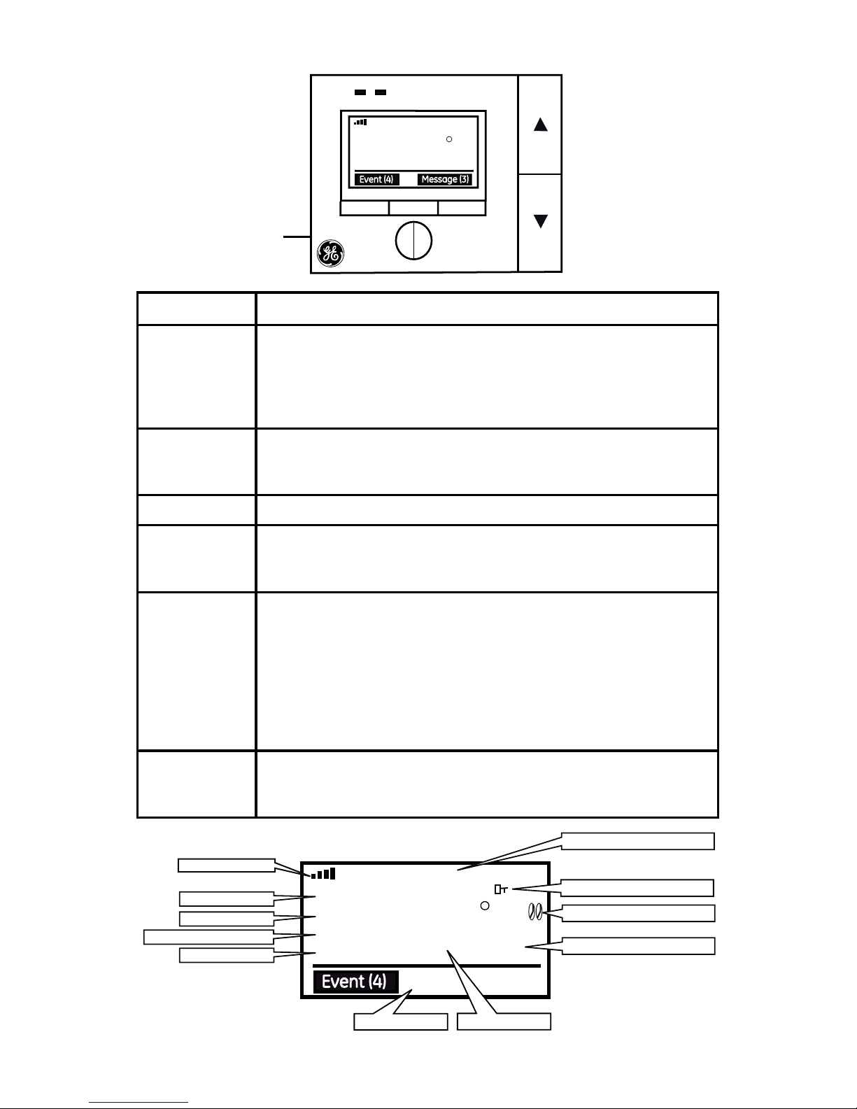
Thermostat Overview
PREV NEXT
THU APR 15 4:30A
HEAT
FAN AUTO
NIGHT
F
62
80
Event (4)
Message (3)
MENU
SELECT
INFO
Key Function
Up/Down • Increase/Decrease a parameter in program mode
• Increase/Decrease temperature setting
• Change system/fan mode setting
• Temporary override
• Lock/Un-lock the keys by pressing both up and down.
Prev/Next • Enters system/fan mode (COOL, OFF, HEAT)
• All menu navigation
• Toggle between fan settings and mode settings
Reset • Power cycles the thermostat
Menu • Enters Navigation menu
• Save current menu settings and return previous menu
screen
Select • Enter sub-menu
• Conrm current menu setting which include, but not limited
to below functions:
• Temporary or permanent override of Demand
Response events.
• Scan/Join/exit Zigbee network
• Get current utilty price and message
• Conrm message or conrm cancel message
Info • Provides information which includes but is not limited to:
• Demand response events list, price list, message list,
device info
Reset
Button
THU APR 15 4:30A
HEAT
FAN AUTO
NIGHT
F
62
70
Event (4)
FILTER
Date and Time
Button Lock Icon
Heat and Cool Output Icon
Set Point Temperature
Room Temperature
Message Area
Filter Warning
Program/Manual/Vacation
Fan Mode
System Mode
Network Icon
Page 5
5
HOME SCREEN
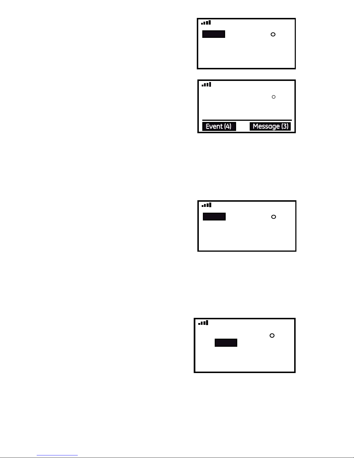
The Home screen is the main display
screen. If you do not press any buttons for
30 seconds, the thermostat will return to
the Home screen.
The large temperature reading on the
Home screen is the current temperature.
The small temperature reading is your
setpoint temperature.
To quickly change the setpoint
temperature: Press UP or DOWN.
Note: The utility company will override
your manually input setpoint when the
unit is set to accept events.
When you receive an event or message from the utility company, ‘Event’
or ‘Message’ appears on the bottom of the Home screen and advises how
many events or messages you have received, and the event’s level of
importance.
THU APR 15 4:30A
HEAT
FAN AUTO
NIGHT
F
62
80
Event (4)
Message (3)
SET HEAT/COOL MODE
1. When you are in the HOME SCREEN,
press PREV and the screen opposite
appears.
2. Press UP or DOWN to select one of the
following options:
• “Heat”, “Cool” or “O” (Conventional HAVC)
• “Heat”, “Emer” (Emergency Heating), “Cool” or “O” (Heat Pump HVAC)
3. Press MENU or wait 5 seconds to conrm your selection and return to
the Home Screen.
THU APR 15 4:30A
HEAT
FAN AUTO
NIGHT
F
62
70
THU APR 15 4:30A
HEAT
FAN AUTO
NIGHT
F
62
70
SET FAN MODE
1. When you are in the HOME SCREEN,
press NEXT and the screen opposite
appears.
2. Press UP or DOWN to select “Fan On” or
“Fan Auto”.
3. Press MENU or wait 5 seconds to conrm your selection and return to
the HOME SCREEN.
NOTE: When the fan is set to AUTO it only runs when the heating/cooling
system is running.
THU APR 15 4:30A
HEAT
FAN
NIGHT
F
62
70
AUTO
Page 6
6
Override Menu
When you receive an event or message from the utility company, “Event”
or “Message” appears on the bottom of the Home Screen and advises
how many events or messages you have received, and the event’s level
of importance. You can view the details by repeatedly pressing INFO (see
the Viewing Events and Messages section for more information.)
In the Override menu, you can choose to accept or reject events, and set
the thermostat to VACATION to override the programmed settings.
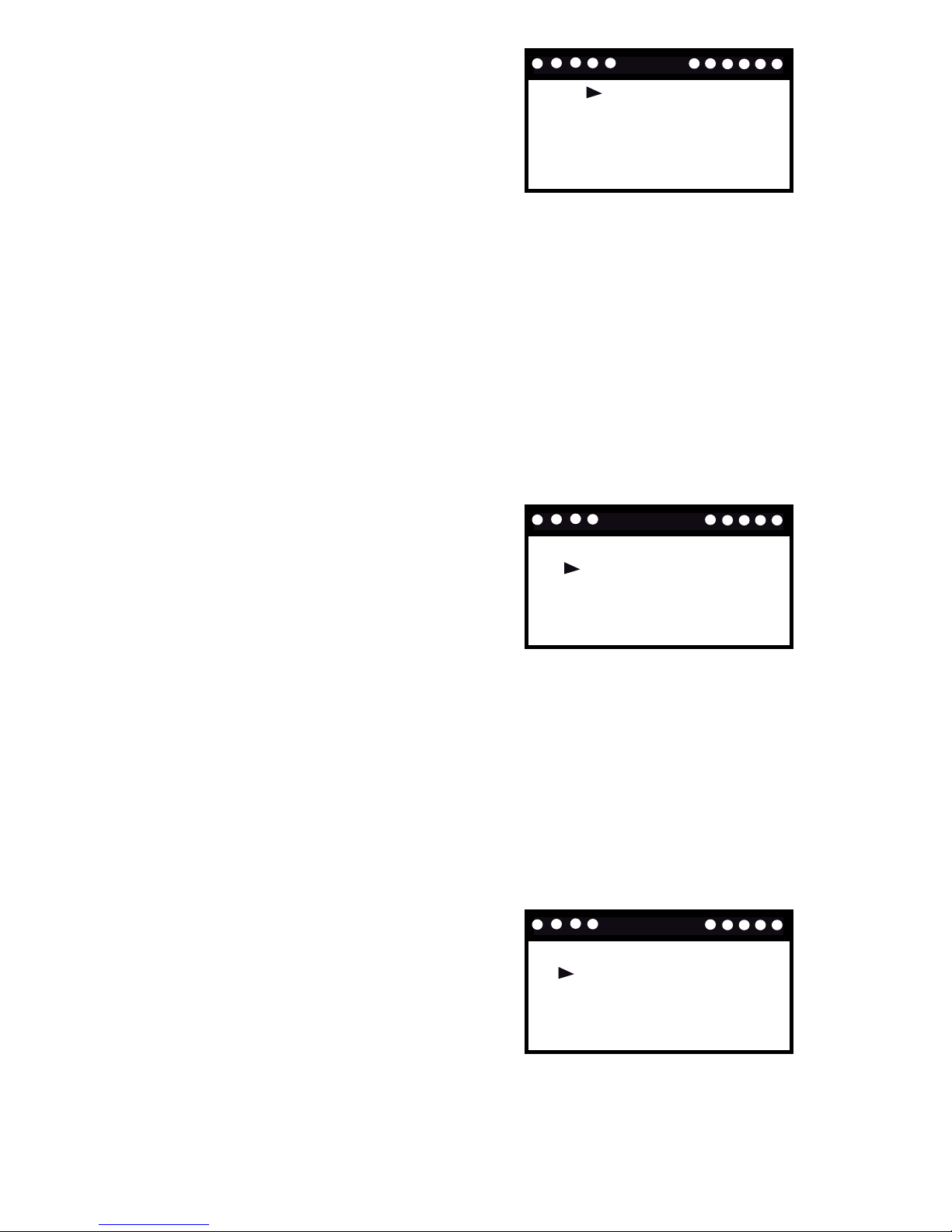
MAIN MENU SETTINGS
1. When you are in the HOME SCREEN,
press MENU and the screen opposite
appears.
2. Press PREV or NEXT to scroll through
the main menu.
3. Press SELECT to enter a menu.
OVERRIDE
PROGRAM
SETUP
NETWORKING
QUERY
AUTO
ACCEPT CURRENT EVENT
ACCEPT ALL EVENTS
VACATION
OVERRIDE
To accept events:
1. Select and enter the Override Menu.
2. Press PREV or NEXT to select “Accept
Current Event” or “Accept All Events”.
3. Press SELECT to conrm.
NOTE: The unit will automatically accept
events unless you have set it to reject events and vice-versa.
REJECT CURRENT EVENT
REJECT ALL EVENTS
VACATION
OVERRIDE
To reject events:
1. Select and enter the Override Menu.
2. Press PREV or NEXT to select “Reject
Current Event” or “Reject All Events”.
3. Press SELECT to conrm. If you reject
an event, a message appears to ask
if you are sure you want to reject it.
Press SELECT to conrm the rejection
or MENU to return to the previous screen.
NOTE: If you have rejected a current event, the unit will continue to
accept all new events. If you have rejected all events, the unit will reject
all events stored on the system and any new events that may occur. To
enable the unit to accept events once again, you must select ‘Accept All
Events’ as shown below.
Page 7

7
VACATION MODE
SETTING DAYS
TEMPERATURE
OFF
:
:
:
30
70F
To set your vacation time:
This setting will override your selected
program settings in the Program Menu
while you are on vacation.
1. Select and enter the Override Menu.
2. Press PREV or NEXT to select “Vacation”
and the opposite screen appears.
3. Press SELECT to conrm.
4. Use PREV or NEXT to scroll through the settings and press SYS or FAN to
change a setting. You must set the ‘Vacation Mode’ to ‘On’ to activate
this function.
5. Press MENU to conrm and return to the previous screen.
When the vacation mode is activated, your utility company can override
your temperature setting when the new event setting saves energy, for
example:
a) In wintertime when the outdoor temperature is cold, you may set your
vacation temperature to 50°F to prevent pipes from freezing. However,
if the utility company sends an event to reduce the temperature to 45°F
to save energy, it will override your vacation temperature and make the
new ‘Heat Set Point’ 45°F.
b) In summertime, if you have set your vacation temperature to 68°F and
the utility sends an event to increase the temperature to 77°F in order
to save energy, it will override your vacation temperature and make the
new ‘Cool Set Point’ 77°F.
Note: The utility company cannot override your vacation temperature if
you have set the unit to ‘Reject All Events’.
Page 8
8
Program Menu
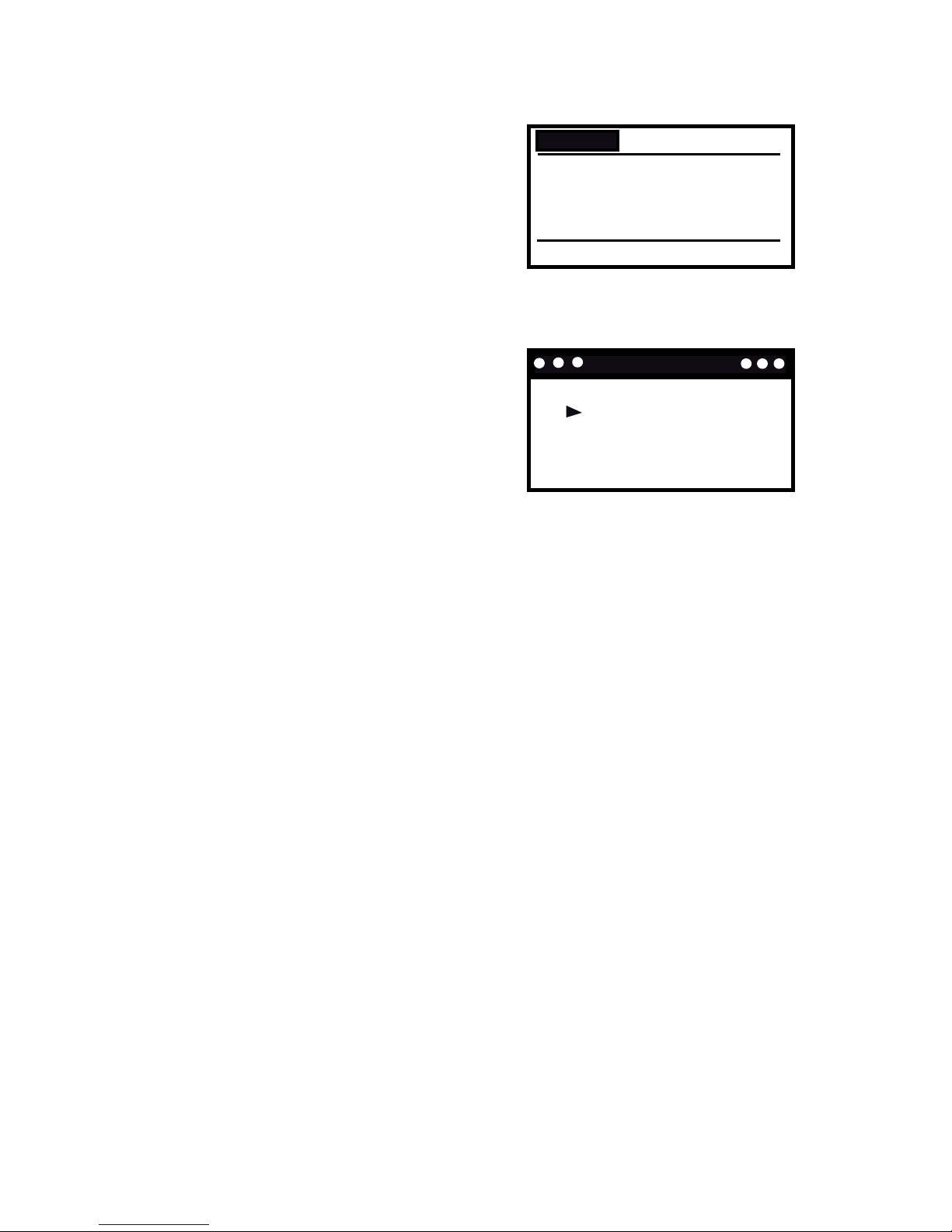
To edit the time and temperature settings for any day of the week:
1. Select and enter the Program Menu
and the screen to the right will appear.
2. Press PREV or NEXT to scroll through
the settings and press UP or DOWN to
change a setting.
3. Press MENU to conrm and return to
the previous screen.
MORN
FVF
NIGHT
TUESDAY
:
:
:
10:00P
HEATCOOL
DAY
:
INFO - - > Copy Or Reset
6:00P
8:00A
6:00A
70
70
65
65
85
75
75
78
To copy or reset a program:
1. Select and enter the Program Menu.
2. Press INFO while displaying the screen
you wish to copy and the screen to the
right appears.
3. Use PREV or NEXT to select ‘Copy
Program’ or ‘Reset program’ and press
SELECT to conrm.
If you selected ‘Copy Program’, you will see a square next to the day
you wish to copy. Use the UP and DOWN buttons to select a the day
that you wish to copy the program to and want the program settings
to be copied to and press SYS until the ‘N’ changes to a ‘Y’. This can be
done for multiple days. Then press SELECT and ‘Successfully Copied’
displays.
If you selected ‘Reset program’, ‘Are you sure you want to RESET the
program?’ appears. Press SELECT to conrm or MENU to exit and return
to the previous screen. When you reset the program, all the Program
menu settings return to the factory default settings.
Copy Program
Reset Program
Copy & Reset
Page 9
9
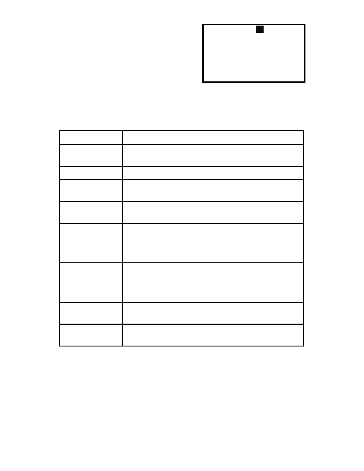
Screen Message
Description
Unit
Changes the display measurement from Celsius to
Fahrenheit or vise-versa.
Span
Changes the temperature span to 0.5°, 1.0°, or 2.0°F.
Fan
The fan will continue to run for 0, 30, 60 or 90 seconds after cooling is turned off.
Filter
Sets a time (up to 500 hours) for the system to
remind you to change or clear the fan’s lter.
Default
If you select this option, ‘Are you sure to RESTORE
all settings to factory default’ displays. Press
SELECT to conrm or MENU to exit and return to the
previous screen.
Time Source
Changes the time source to either user setting or utility setting. If the Network setting is selected, press
Info to obtain the network time. It will be reected on
the Home Screen.
Time
Changes the time. Only visible if Time Source is set
to Setting.
Date
Changes the time. Only visible if Time Source is set
to Setting.
Setup Menu
To edit the Setup menu:
1. Select and enter the Setup Menu and
the screen to the right will appear.
2. Press PREV or NEXT to scroll through
the settings and press UP or DOWN to
change a setting.
3. Press MENU to conrm. Here is a list of
what the Setup menu settings mean:
UNIT
SPAN
FAN
FILTER
DEFAULT
TIME
DATE
F
:
:
:
:
:
:
:
1.0 F
60 SECONDS
001/500 HOURS
NO
5:56A
APR 15 2010
TIME SOURCE
:
Setting
Page 10
10
STATE
CHANNEL
16
:
:
Not Connected
Networking Menu
The networking menu advises if the thermostat is communicating with
your utility network or if you are disconnected from the network.
To connect to your utility network:
1. Select and enter the Network Menu.
2. If you are not connected to your utility
network, the “Not Connected” screen
appears.
3. Press UP or DOWN to select one of the
following:
• Auto – enables an automatic scan and join for all the channels (starting
from channel 11).
• All – searches all channels and returns a list of all available networks.
• Channel – Searches the selected network channel and returns a list of
available networks on that particular channel.
4. Press SELECT to conrm the selection.
5. If ‘Auto’ was selected, the thermostat will automatically scan the
available network channels and join the allowed network. Upon a
successful network join, the ‘Joined’ screen appears. It may take up to
a minute for the connection process to complete.
6. If ‘All’ was selected, the thermostat will scan all available networks and
return a list. Use UP or DOWN to select a network. Press SELECT to join.
Upon a successful network join, the ‘Joined’ screen appears. It may
take up to a minute for the connection process to complete.
7. If ‘Channel’ was selected, use UP or DOWN to select the particular
channel of your network. Press SELECT to initiate the scan. Use UP or
DOWN to select the network from the returned list. Press SELECT to
join the selected network. Upon a successful network join, the ‘Joined’
screen appears. It may take up to a minute for the connection process
to complete.
To disconnect from your utility network:
1. Select and enter the Networking menu.
You should see the ‘Joined’ screen
opposite.
2. Press SELECT to disconnect and the
message ‘Are you sure?’ appears.
3. Press SELECT again to conrm. Press UP or DOWN to move the cursor
between YES and NO.
STATE
SELECT To Disconnect
CHANNEL
PAN
ID
:
:
:
:
Joined
16
0x3333
0100000000000000
Page 11

11
GET EVENT
GET CURRENT PRICE
GET SCHEDULE PRICE
GET LAST MESSAGE
QUERY
Query Menu
The query menu allows you to retrieve and
view recent events, prices or messages
from your utility company.
To connect to your utility network:
1. Select and enter the Query Menu and
the screen to the right appears.
2. Press UP or DOWN to scroll through the on screen queries and press
SELECT to enter the menu option.
• Get current price – When you select this option your request to be
notied of the current price options will automatically be sent out.
• Get schedule price – Follow the same steps as ‘Get event’ to
automatically send out your request for the schedule price.
• Get last message – When you select this option your request to be
notied of your last message received will automatically be sent out.
Note:
• If ‘Please join network rst!’ appears on the display, you need to connect
your thermostat to the utility network (see the Networking menu section
for details). Press MENU to return to the previous screen.
• A reply to your query should be received within 15 seconds.
Page 12
12
Screen Message
Description
An Event
A Price
Your current energy usage is
priced at Level 1, which is currently
$2.2 per kilowatt-hour.
INFO
VIEWING EVENTS AND MESSAGES
1. When you are in the HOME SCREEN, press INFO repeatedly to view the
following notications from your utility company:
EVENT:
• Pending - An event will happen at
the START TIME.
• Active - This event is currently in
progress.
• Rejected - You have rejected this
event.
LEVEL: There are 9 different event
levels:
• Green - Energy Saving
• Levels 1-5 - Level of message
importance; 1 is low and 5 is high.
• Emergency
• Planned Outage
• Service Disconnect
START TIME: The event will start at
this time (i.e., 8am)
DURATION: This event will last for
this amount of time (i,e., 2 hours)
EVENT
LEVEL
START TIME
DURATION
:
:
:
:
Pending 1/4
Green
8:00A
02:00
CURRENTPRICE
LEVEL 2
LEVEL 1
LEVEL 1
2.2/kWh
3.4/kWh
:
:
:
Page 13
13
Screen Message
Description
A message
Network Information
Your utility company will send you a
wide range of messages.
If the utility company asks you to
conrm a message or conrm your
cancellation command from a previous message, press SELECT to
conrm.
MESSAGE
Hello,
:
1/4
SUPPORT
CHANNEL: 16
SHORT: 0X05D9
PAN: 0x3333
:
1/2
MESSAGE
Your request has been
rejected.
:
2/4
Confirm
CHANNEL - Write down your
channel number and put it in a
safe place. It may be useful if you
need to reconnect to the network.
SHORT/PAN/EPAN/EUI64/FIRM/
HVAC - if you phone for support
you may be asked to provide
these codes.
2. When viewing any of these screens look in the top right hand corner
to see how many pages there are, i.e., 1/2. Use the PREV and NEXT
buttons to scroll through all the pages.
Page 14
14
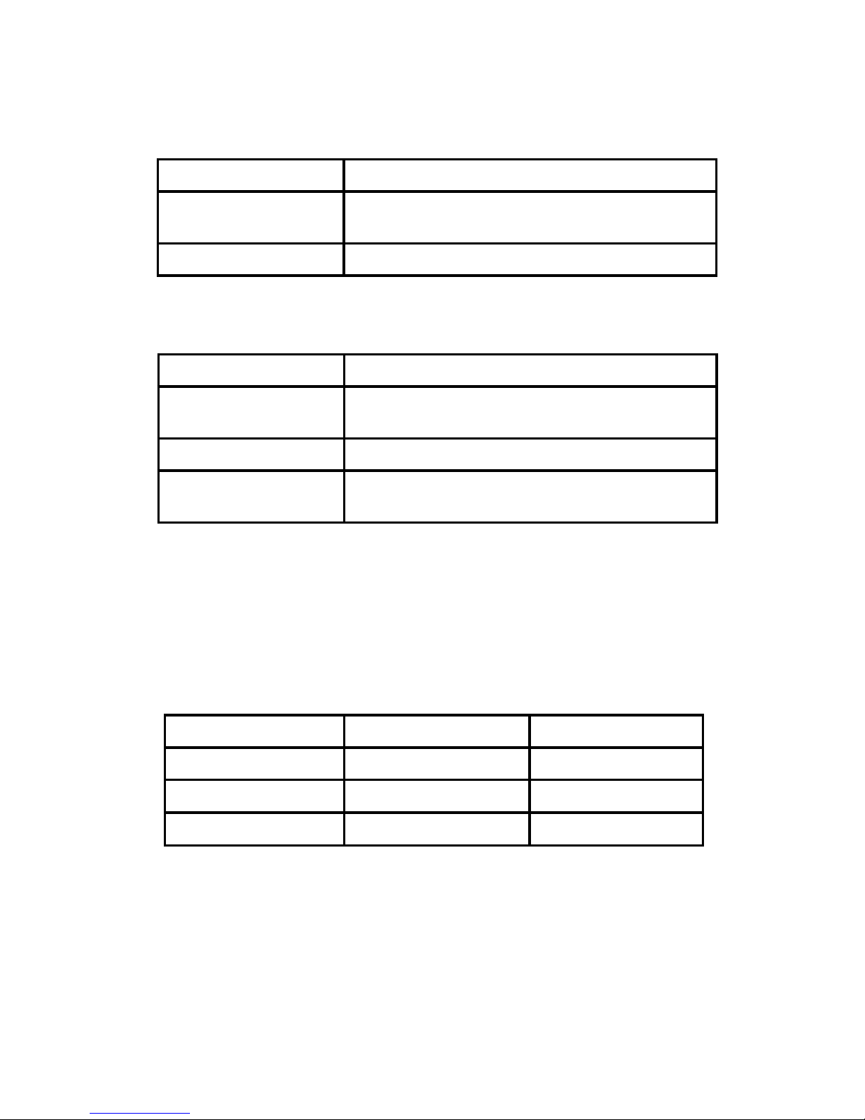
PRICE TEMPERATURE OFFSET
There are two LEDs located in the top left corner of the front of the
thermostat. See the table below for a description of what the lights mean:
Energy Level
LED Indicator
Offset (in °F)
Medium
Green 2
High
Orange
3
Critical
Red
4
For example, if the current programmed temperature is 75°F and the
current price level from the utility company is High (orange), the actual
setpoint for the home will be 79°F.
RESET
To reset the unit, insert a thin, blunt instrument into the RESET hole on
the side of the unit. Please note that resetting the unit will return it to the
factory default settings.
INDICATORS
There are two LEDs located in the top left corner of the front of the
thermostat. See the table below for a description of what the lights mean:
Yellow LED indicates the status of the HVAC system
Tri-color (red, green and orange) LED indicates the status of the
information from your utility company.
Off
HVAC system is working normally
Flashing
HVAC system is working normally and is communicating to the server or utility company.
On
HVAC system error/warning
Green LED on
Current energy price is at a Low level.
Orange LED on
Current energy price is at a Medium or High
level.
Red LED on
Current energy price is at a Critical level.
Flashing
If the current LED color is ashing it means
the thermostat has received a new message.
Page 15

15
FCC DECLARATION
WARNING: Changes or modications to this unit not expressly approved
by the party responsible for compliance could void the user’s authority to
operate the equipment.
This device complies with Part 15 of the FCC Rules. Operation is subject
to the following two conditions: (1) this device may not cause harmful
interference, and (2) this device must accept any interference received,
including interference that may cause undesired operation.
NOTE: This equipment has been tested and found to comply with the limits
for a Class B digital device, pursuant to Part 15 of the FCC Rules. These
limits are designed to provide reasonable protection against harmful
interference in a residential installation. This equipment generates, uses
and can radiate radio frequency energy and, if not installed and used in
accordance with the instructions, may cause harmful interference to radio
communications. However, there is no guarantee that interference will
not occur in a particular installation. If this equipment does cause harmful
interference to radio or television reception, which can be determined by
turning the equipment o and on, the user is encouraged to try to correct
the interference by one or more of the following measures:
· Reorient or relocate the receiving antenna.
· Increase the separation between the equipment and receiver.
· Connect the equipment into an outlet on a circuit dierent from that to
which the receiver is connected.
· Consult the dealer or an experienced radio/TV technician for help.
FCC RF Radiation Exposure statement:
This equipment complies with FCC RF radiation exposure limits set forth
for an uncontrolled environment. This equipment should be installed
and operated with a minimum distance of 20 centimetres between the
radiator and your body.
Page 16
16
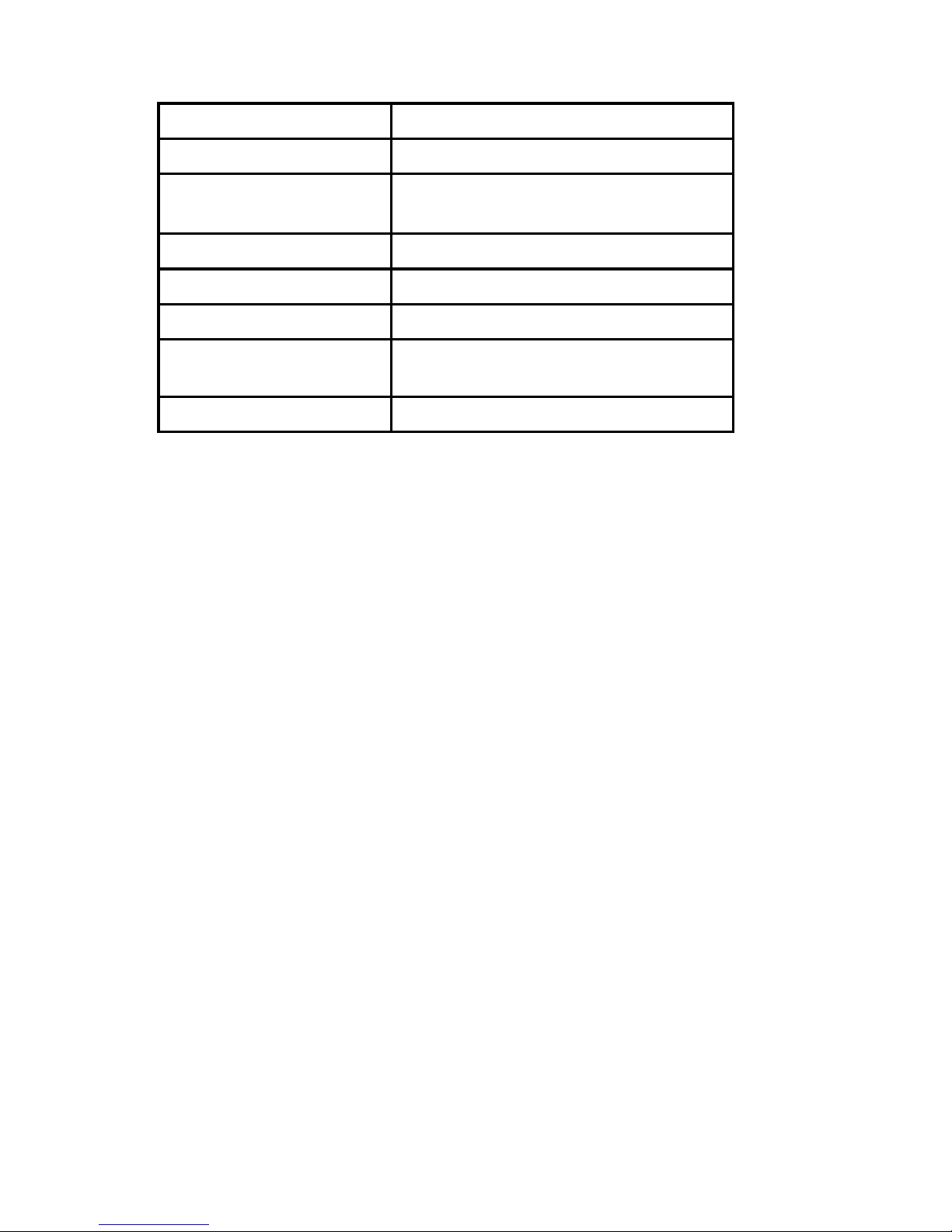
Specications
Temperature Unit
°C/°F
Operating Temperature
32-113°F (0-45°C)
Indoor Temperature
Measurement Range
40-99°F (5-37°C)
RF Frequency
2.40-2.48 GHz
RF Range
Up to 1300 ft (400 m) line of sight
A/C Adapter Input
18-30 V AC at R and C terminals
Size
5.4” (L) x 4.2” (W) x 1” (H)
13.6 (L) x 10.6 (W) x 2.6 (H) cm
Weight
0.76 lb (345 g)
Page 17

17
Notes
Page 18

18
Limited Warranty for GE Programmable Thermostat
WARRANTY
Your use of the GE Programmable Thermostat (“Hardware”), online product
registration of the Hardware, or your return of the enclosed Registration Card
acknowledges that you have read and agree to the terms of this warranty
agreement. GE’s warranty obligations for this Hardware product are limited to
the terms set forth herein.
GE warrants that this Hardware product shall be free of defects in materials
and workmanship under normal use for a period of one (1) year from the date
of original retail purchase (“Warranty Period”). If a hardware defect arises and
a valid claim is received within the Warranty Period, your sole and exclusive
remedy will be for GE, in its sole discretion and to the extent permitted by law,
to (1) repair the hardware defect at no charge, using new parts or refurbished
parts, (2) exchange the Hardware product with new or refurbished Hardware
product that is functionally equivalent to the original Hardware product,
or (3) refund the purchase price of the Hardware product. Any repaired or
replacement Hardware product will be warranted for the remainder of the
original warranty period or thirty (30) days, whichever is longer. In order to
receive the remedy set forth above, you must contact GE during the Warranty
Period at 800-220-6899 and provide the model number, serial number, date
of purchase and MAC ID number of your unit. Upon GE’s determination that
the Hardware product should be returned to GE, return the Hardware product
and include with each returned Hardware product (i) a copy of your original
purchase invoice or receipt to verify your warranty; (ii) your name, address, and
telephone number; (iii) the Return Materials Authorization (RMA) number. You
are responsible for properly packaging and shipping the Hardware product at
your cost and risk.
In addition to the foregoing Hardware product warranty, for a period of ninety
(90) days from the date of original retail purchase, GE shall also provide telephone (800-220-6899) and web chat (www.gebrillion.com) technical support
assistance.
Please note that the above warranty obligations of GE do not include any
in-home installation or service.
Important: Do not open the Hardware product. Opening the Hardware
product may cause damage that is not covered by this warranty. Only GE or
a GE authorized service provider should perform service on this Hardware
product.
TO THE EXTENT PERMITTED BY LAW, THIS WARRANTY AND THE REMEDIES
SET FORTH ABOVE ARE EXCLUSIVE AND IN LIEU OF ALL OTHER WARRANTIES, REMEDIES AND CONDITIONS, WHETHER ORAL, WRITTEN, STATUTORY,
EXPRESS OR IMPLIED, AS PERMITTED BY APPLICABLE LAW, GE SPECIFICALLY
DISCLAIMS ANY AND ALL STATUTORY OR IMPLIED WARRANTIES, INCLUDING, WITHOUT LIMITATION, WARRANTIES OF MERCHANTABILITY AND
FITNESS FOR A PARTICULAR PURPOSE AND WARRANTIES AGAINST HIDDEN
OR LATENT DEFECTS. IF GE CANNOT LAWFULLY DISCLAIM STATUTORY OR
IMPLIED WARRANTIES THEN TO THE EXTENT PERMITTED BY LAW, ALL SUCH
WARRANTIES SHALL BE LIMITED IN DURATION TO THE DURATION OF THE
EXPRESS WARRANTY AND TO THE REPAIR OR REPLACEMENT SERVICE AS
DETERMINED BY GE. No oral or written information or advice given by GE or
a GE-authorized representative shall modify or extend this warranty. If any
term is held to be illegal or unenforceable, the legality or enforceability of
the remaining terms shall not be affected or impaired.
Page 19

19
EXCLUSIONS AND LIMITATIONS—This warranty applies only to the
Hardware product manufactured by or for GE that can be identified by
the “GE” trademark, trade name, or logo affixed to it. This warranty
does not apply to any non-GE hardware product or any software, even
if packaged or sold with the Hardware. Software distributed by GE
with or without the GE brand name (including, but not limited to system
software) is not covered under this warranty. Refer to the End User
Licensing Agreement accompanying the software for details of your
rights with respect to its use.
GE does not warrant that the operation of the product will be
uninterrupted or error-free. GE is not responsible for damage arising
from failure to follow instructions relating to the product’s use.
This warranty does not apply to: (a) consumable parts, such as batteries,
or protective coatings designed to diminish over time unless failure
has occurred due to a defect in materials or workmanship; (b) cosmetic
damage; (c) damage caused by use with non-GE products; (d) damage
caused by accident, abuse, misuse, liquid contact, fire, earthquake or
other external causes; (e) damage caused by operating the Hardware
product outside the permitted or intended uses described by GE; (f)
damage caused by service (including upgrades and expansions) not
performed by GE, a GE-authorized service provider, or an authorized
representative of GE; (g) a product or part that has been modified to
alter functionality or capability without the written permission of GE; (h)
defects caused by normal wear and tear or otherwise due to the normal
aging of the product; (i) removed or defaced GE serial numbers; or (j)
damage caused by or via the network on which the Hardware product is
used including, but not limited to, any online intrusion or attack.
EXCEPT AS PROVIDED IN THIS WARRANTY AND TO THE MAXIMUM EXTENT
PERMITTED BY LAW, GE IS NOT RESPONSIBLE FOR DIRECT, SPECIAL, INCIDENTAL OR CONSEQUENTIAL DAMAGES RESULTING FROM ANY BREACH OF
WARRANTY OR CONDITION, OR UNDER ANY OTHER LEGAL THEORY, INCLUDING BUT NOT LIMITED TO LOSS OF USE; LOSS OF REVENUE OR ACTUAL OR
ANTICIPATED PROFITS OR SAVINGS; LOSS OF, DAMAGE TO, COMPROMISE
OR CORRUPTION OF DATA; OR ANY INDIRECT OR CONSEQUENTIAL LOSS OR
DAMAGE HOWSOEVER CAUSED INCLUDING THE REPLACEMENT OF EQUIPMENT AND PROPERTY AND ANY COSTS OF RECOVERING, PROGRAMMING
OR REPRODUCING ANY PROGRAM OR DATA STORED IN OR USED WITH THE
GE PRODUCT. THE FOREGOING LIMITATION SHALL NOT APPLY TO DEATH OR
PERSONAL INJURY CLAIMS, OR ANY STATUTORY LIABILITY FOR INTENTIONAL
AND GROSS NEGLIGENT ACTS AND/OR OMISSION.
Warrantor: General Electric Company. Louisville, KY 40225
Page 20
20
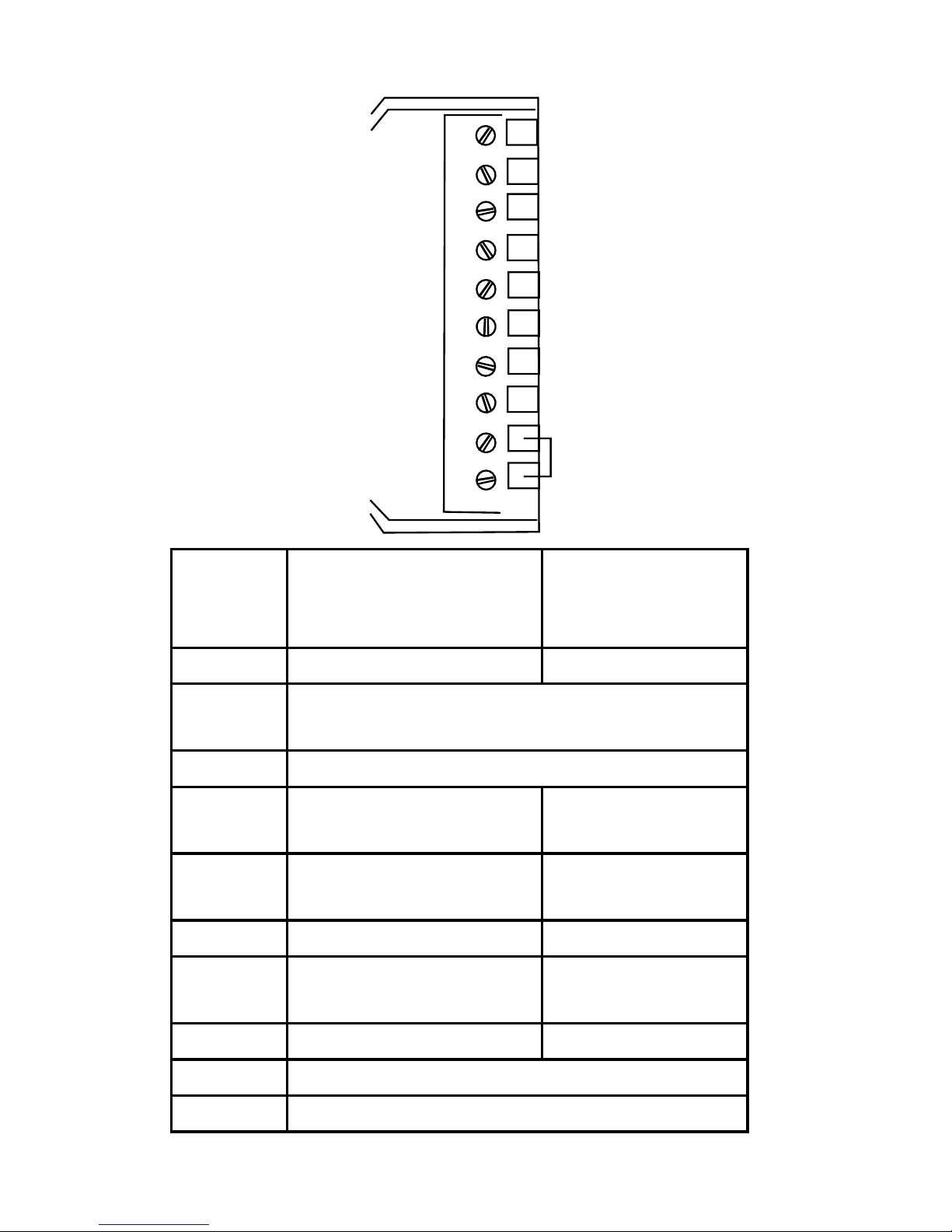
Terminal Denition
L
C
G
Y
Y2
W
W2/E
W3/O/B
RH
RC
Terminal Convectional Heat
Cool
System
Heat Pump
System
L No Use System Monitor
C 24VAC Common for control ciruit and thermo-
stat power input
G FAN
Y 1st stage cooling 1st stage
compressor
Y2 2nd stage cooling 2nd stage
compressor
W 1st stage heating Auxiliary heating
W2/E 2nd stage heating Emergency
heating
W3/O/B 3rd stage heating Changeover Valve
RH 24VAC Power supply for Heating side
RC 24VAC Power supply for Cooling side
Page 21
21
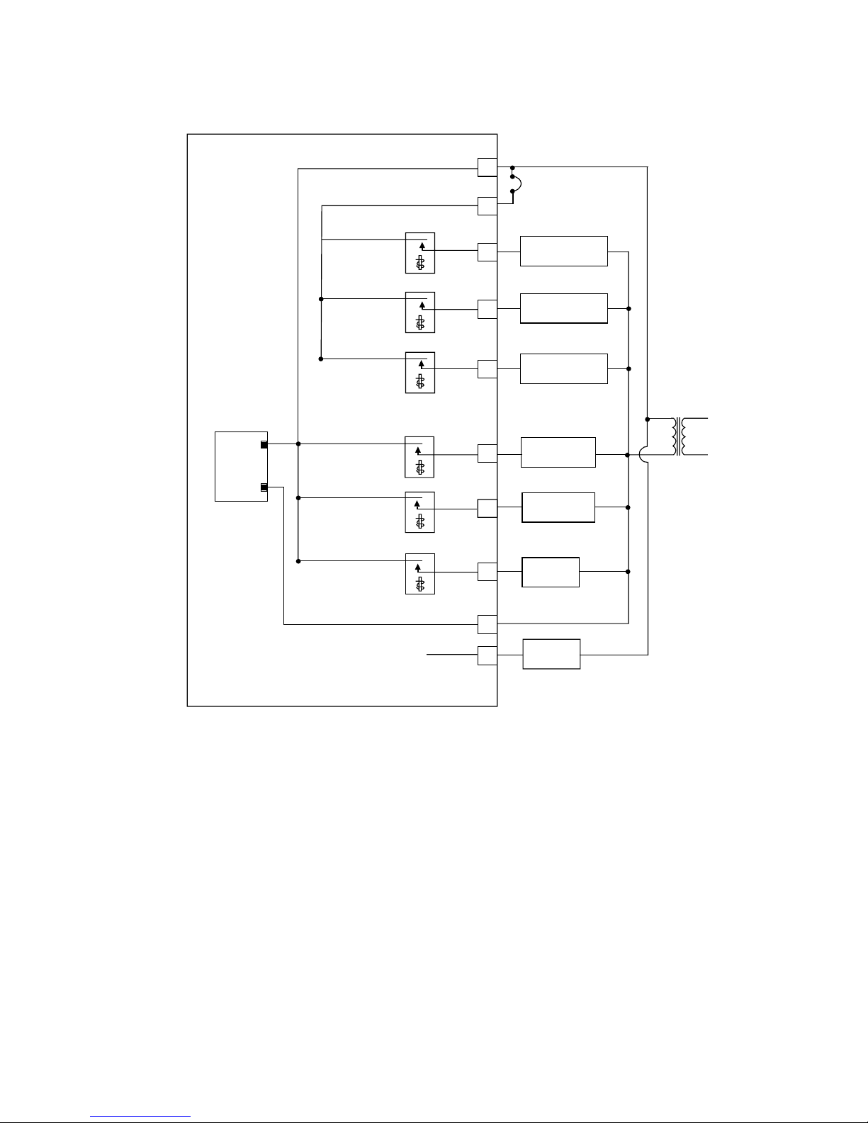
Transformer
O/B relay
O/B
E
W
Rc
RH
Y
Y2
G
L
C
Changeover Valve
Aux Heang
Emergency
Emergency relay
Auxiliary heang relay
1st Compressor Relay
2nd Compressor Relay
Fan relay
AC_ IN
Power Supply
AC_ IN
MCU
1st Compressor
2nd Compressor
Jum
per W ire
FAN
FAULT DETECT
Heat Pump
24VAC
Wiring Diagram for Heat Pump System
Page 22
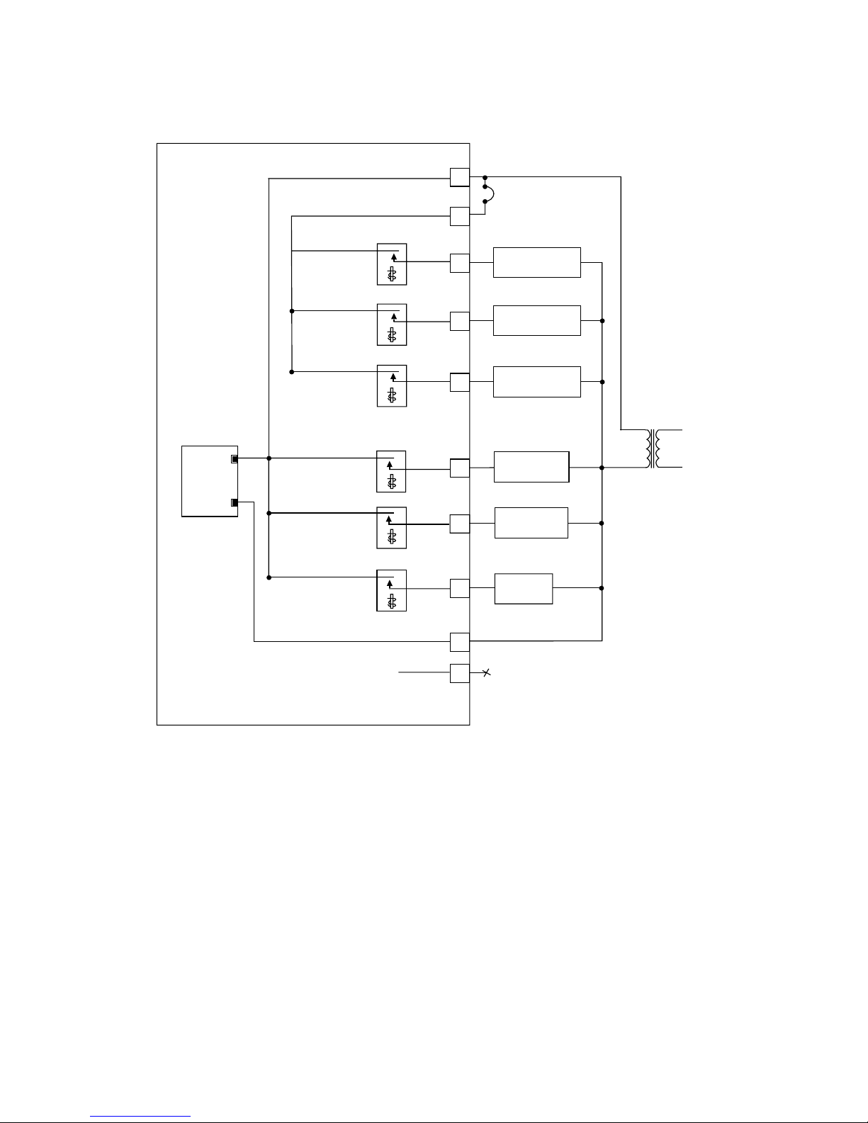
22
1st heang relay
W3
W2
W
Rc
RH
Y
Y2
G
L
C
3rd HEATING
1st HEATING
2nd HEATING
Transformer
2nd heang relay
3rd heang relay
1st cooling relay
Fan relay
AC_ IN
Power Supply
AC_ IN
1st Cooling
2nd Cooling
Jumper Wire
FAN
24VAC
Heat
Cool
2nd cooling relay
Wiring Diagram for Conventional Heat/Cool
System
Page 23

23
Notes
Page 24

24
Notes
 Loading...