

Page 1
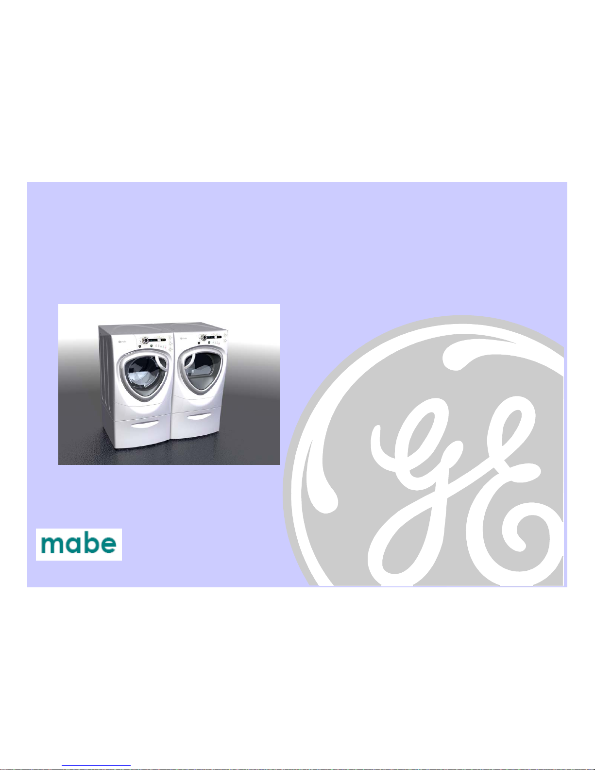
New GE Profile Front Load Washer
WPDH8800J
Pub # 08-MAN-AW-04Robert Gauthier, Training & Technical Support (31-9168)
Page 2
2
IMPORTANT SAFETY NOTICE
Warning: This information is intended for use by individuals possessing
adequate backgrounds of electrical, electronic and mechanical experience.
Any attempt to repair a major appliance may result in personal injury and
property damage. The manufacturer or seller cannot be responsible for the
interpretation of this information, nor can it assume any liability in connection
with its use.
CAUTION
To avoid personal injury while servicing this unit, disconnect power before
servicing. If grounding wires, screws, straps, clips, nuts, or washers used to
complete a path to ground are removed for service, they must be returned to
their original position and properly fastened.
CONFIDENTIAL AND PROPRIETARY INFORMATION-NOT FOR PUBLIC DISCLOSURE. September 2008
Page 3
3
Table of Contents
Circuit Board Connections
9
Clean Pump Filter
6
Component Locator Views
7, 8
Control Board
15, 16, 17
Control Panel 13, 14
Dampers 48, 49
Diagnostic Test s 55, 56, 57, 58, 59, 60
Dispenser Assembly 23, 24, 25, 26, 27
Door 43, 44, 45, 46, 47
Door Lock 20, 21
Error Codes 61, 62, 63, 64, 65, 66 67
Front Panel 22
GE Prof
ile Washer – New Features
5
GE Profile Washer Warrant
y
4
Heater Ass embly 36
Inverter 37, 38, 39
Inverter Boar
d
10
Line Filter 18, 19
Motor Assembly 40, 41, 42
Power Board Assembly 28, 29
Power Supply Board (rear cover of
f
)
12
Power Supply Board (rear cover on
)
11
Pump 35
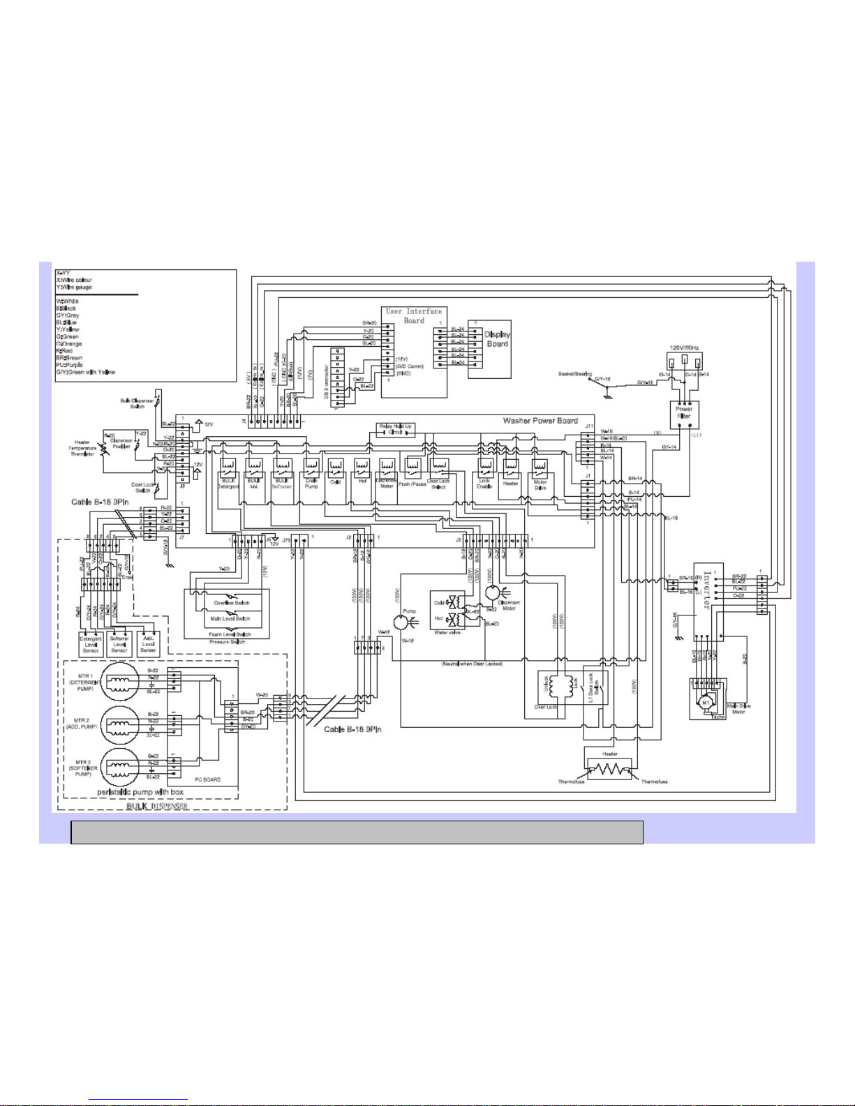
Schematic 68
Service Test Mode 50, 51, 52, 53, 54
Water Level Control 30, 31, 32, 33
Water Valve 34
CONFIDENTIAL AND PROPRIETARY INFORMATION-NOT FOR PUBLIC DISCLOSURE. September 2008
Page 4
4
GE Profile Washer Warranty
For The Period Of:
One Year Any part From the date of original purchase
.
Any part of the washer which fails due to a defect in materials or workmanship. During this
limited one-year warranty, GE will also provide, free of charge, all labor and related service
costs to replace the defective part.
Second through Fifth Year From the date of the original purchase
The suspension strut assembly, motor and motor controller if any of these parts should fail due
to a defect in materials or workmanship. GE will also replace the washer top panel, front panel
or service panel if they should rust under operating conditions. During this additional three-year
limited warranty, you will be responsible for any labor or related service costs.
Second through Tenth Year From the date of the original purchase
The outer tub and driven pulley if any of these parts should fail due to a defect in materials
or workmanship. During this additional eight-year limited warranty, you will be responsible
for any labor or related service costs.
Lifetime of Product From the date of the original purchase
The washer basket if it should fail due to a defect in materials or workmanship. During this
product lifetime limited warranty, you will be responsible for any labor or related service costs.
CONFIDENTIAL AND PROPRIETARY INFORMATION-NOT FOR PUBLIC DISCLOSURE. September 2008
Page 5
5
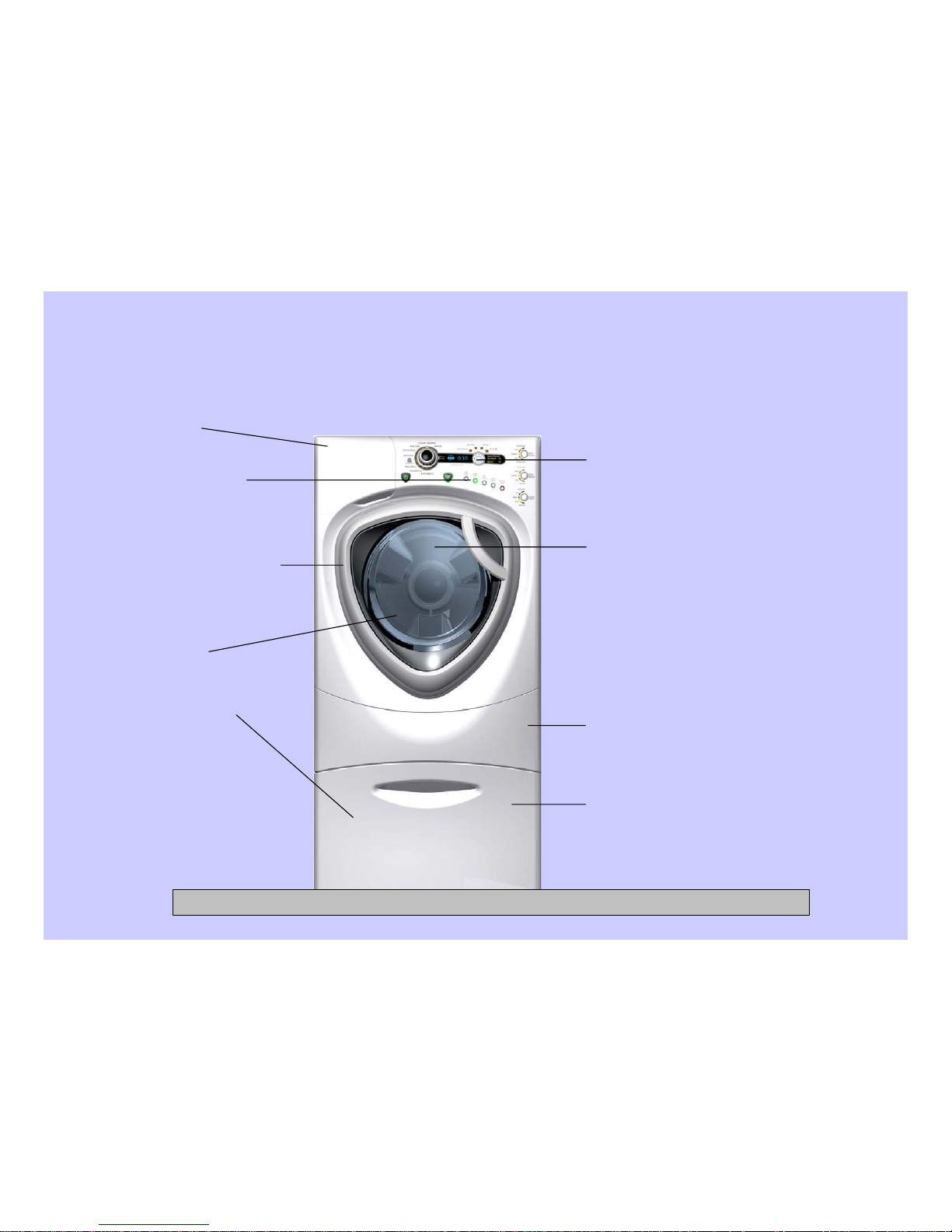
Increased Basket Capacity:
Minimum 3.35 DOE [3.9 IEC]
Modern Control Interface:
GE designed controls with VFD,
Radial Knob, and Keypad
New Front Panels & Door:
New panels and door
assembly to mount on
Magellan cabinet chassis
Quiet Pack:
Sound insulation added for lower
noise
Communication with
Dryer:
Internal harness and
connector for sending
cycle information to Dryer
Higher Spin Speed:
Minimum 1300 RPM
Bulk Dispense Ready:
All units with built in
tubing and wiring
connection located on rear
of unit, ready for future
Bulk Dispenser Module
program
Tall Pedestal Option:
14” Tall Pedestal with Drawer for
more storage space
Improved Dispenser:
GE Profile Washer – New Features
CONFIDENTIAL AND PROPRIETARY INFORMATION-NOT FOR PUBLIC DISCLOSURE. September 2008
Page 6
6
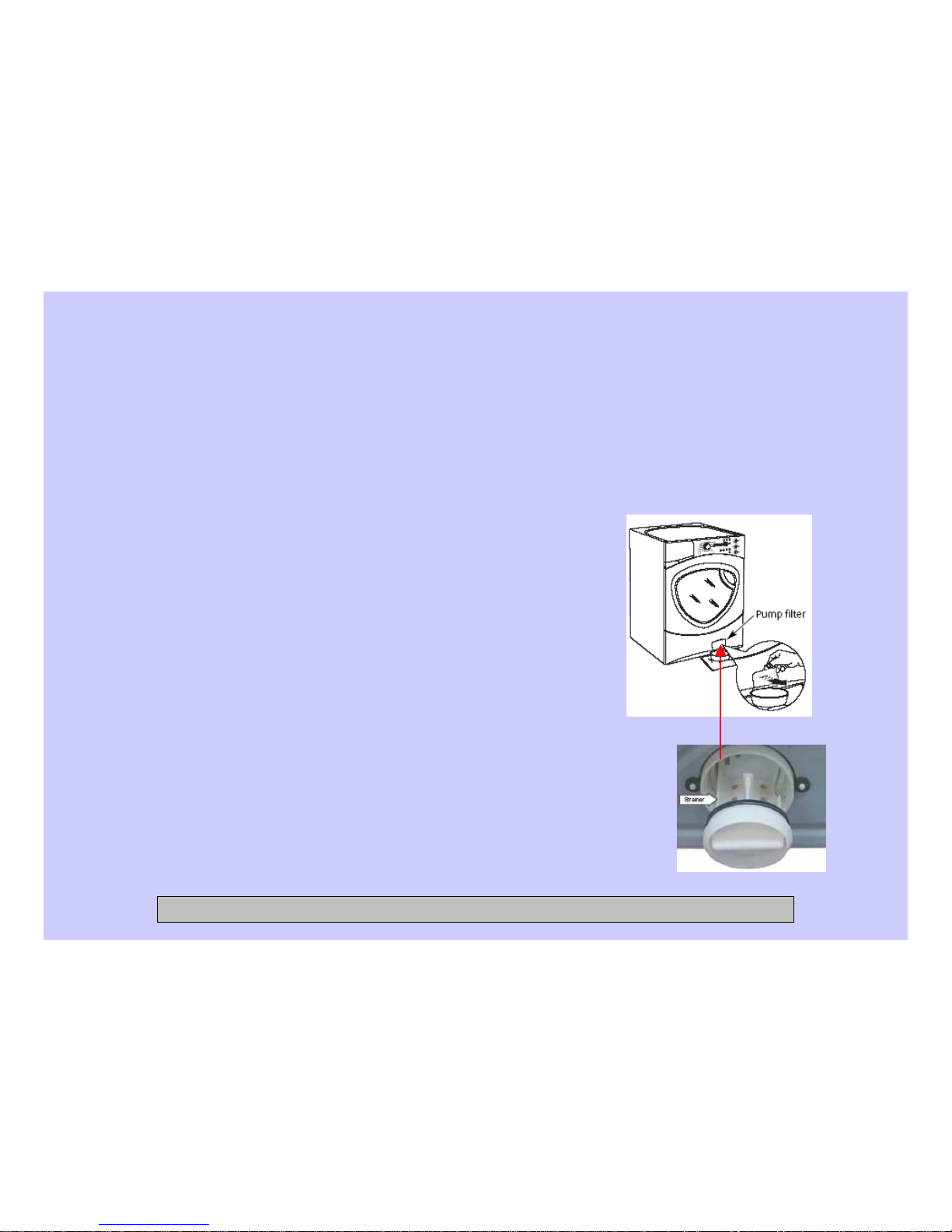
Clean Pump Filter
Due to the nature of the front-load washer, it is sometimes possible for small
articles to pass to the pump. The washer has a filter to capture lost items so they
are not dumped to the drain.
To retrieve lost items, clean out the pump filter.
1) Using a coin in the notch on the door, open the
access door.
2) Place a shallow pan or dish under the pump
access door and towels on the floor in front of
the washer to protect the floor. It is normal to
catch about a cup of water when the filter is
removed.
3) Turn the pump filter counterclockwise and
remove the filter.
4) Clean the debris from the filter.
5) Replace the filter and turn clockwise to the
marked position.
6) Close the access door.
CONFIDENTIAL AND PROPRIETARY INFORMATION-NOT FOR PUBLIC DISCLOSURE. September 2008
Page 7
7
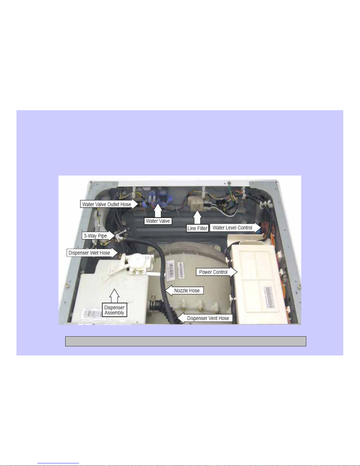
Component Locator Views
Top View
CONFIDENTIAL AND PROPRIETARY INFORMATION-NOT FOR PUBLIC DISCLOSURE. September 2008
Page 8
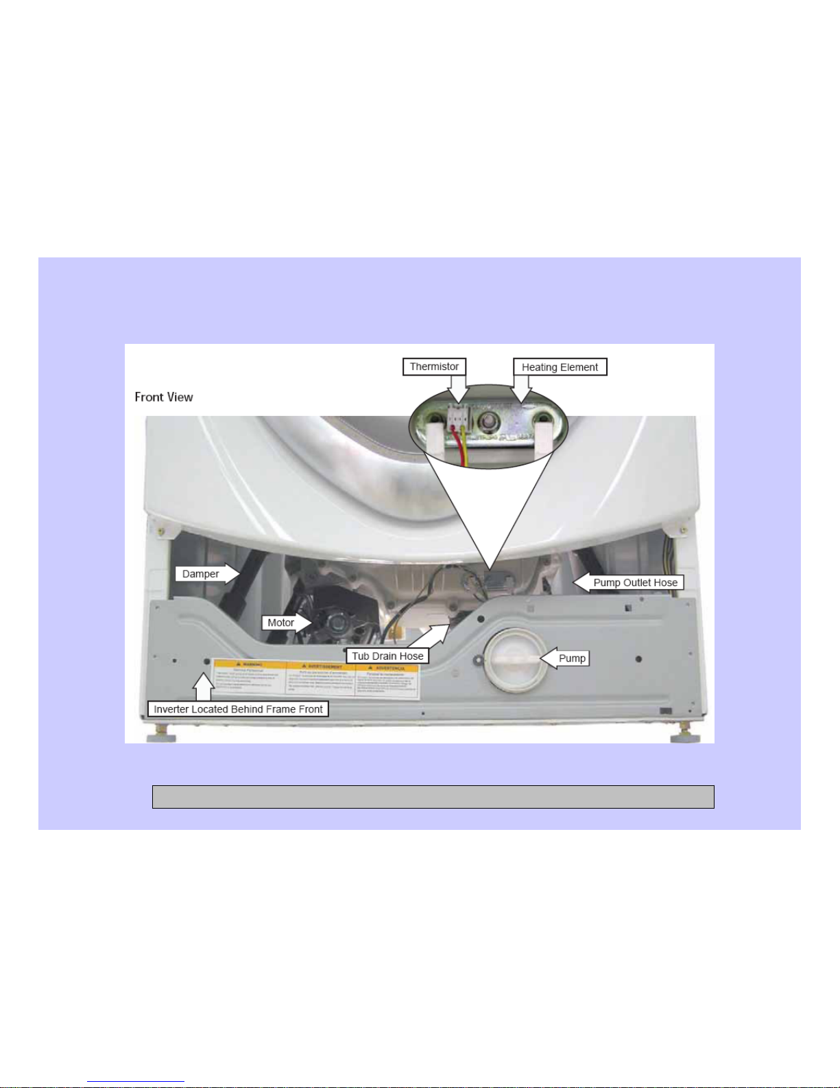
8
Front View
CONFIDENTIAL AND PROPRIETARY INFORMATION-NOT FOR PUBLIC DISCLOSURE. September 2008
Page 9
9
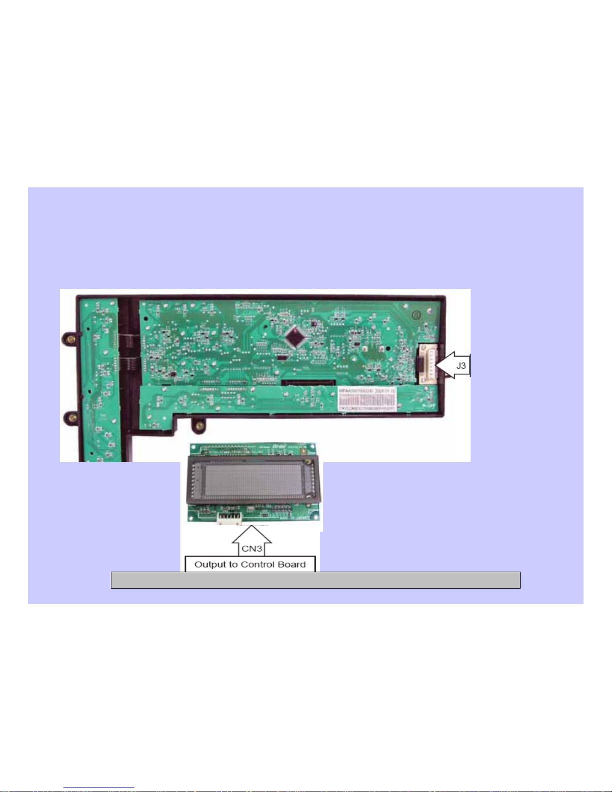
Circuit Board Connections
Control Board
Input from
Power Board
VFD (Vacuum Fluorescent Display)
CONFIDENTIAL AND PROPRIETARY INFORMATION-NOT FOR PUBLIC DISCLOSURE. September 2008
Page 10
10
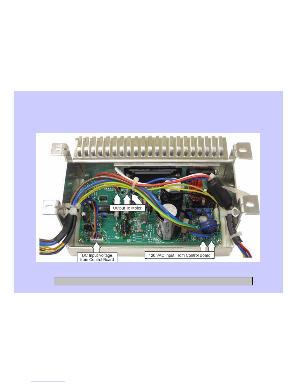
Inverter Board
CONFIDENTIAL AND PROPRIETARY INFORMATION-NOT FOR PUBLIC DISCLOSURE. September 2008
Page 11
11
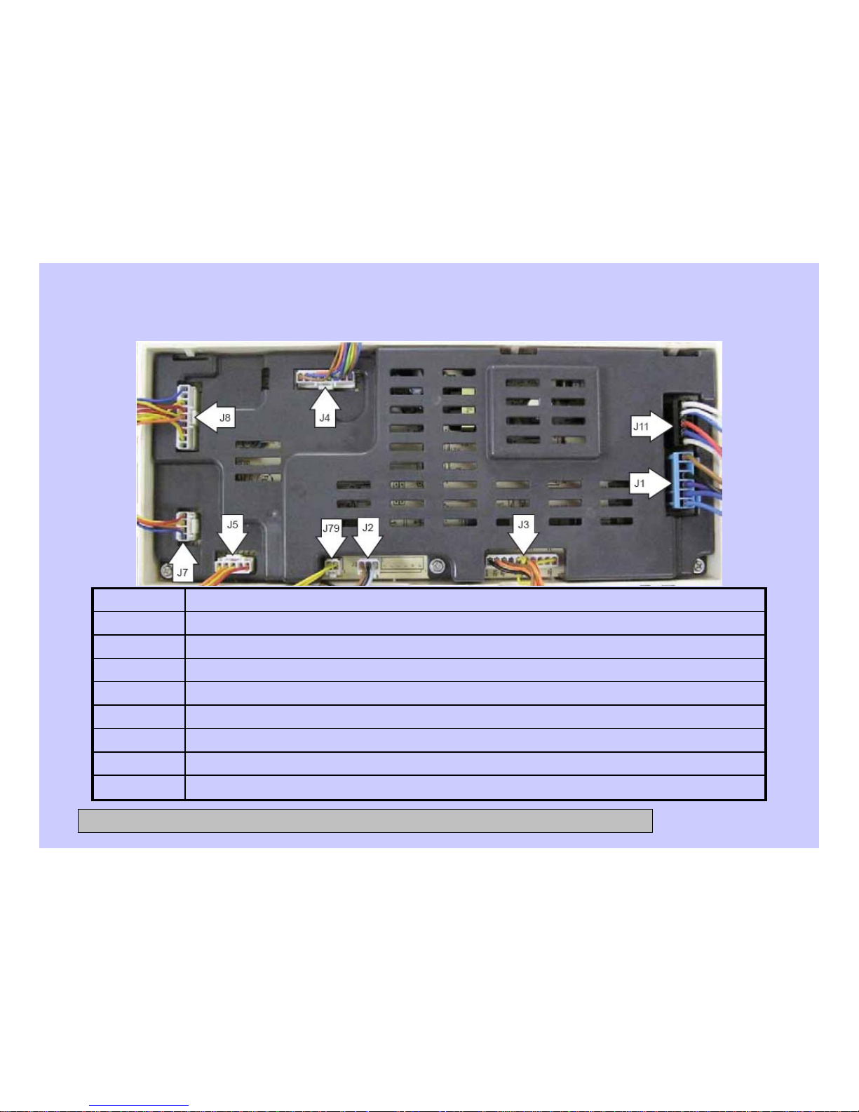
Power Supply Board (rear cover on)
Motor tachometer
J79
L1 door lock switch, heater, N to inverter, N to bulk dispenser board, N to power filter
J11
Bulk dispenser switch, dispense position switch, heater temperature thermistor, door lock switch
J6
Detergent and softener level sensors
J7
Pressure switch: foam, main, and overflow switches
J5
7V and 12V to UI, LIN bus, ground to UI and inverter, Ezlink tx, tx, and 5V to inverter
J4
Door lock and unlock solenoids, dispenser motor, hot and cold water valves, water pump
J3
Softener pump, detergent pump motors
J2
L1 output to inverter, door lock switch, heater, and power filter
J1
CONFIDENTIAL AND PROPRIETARY INFORMATION-NOT FOR PUBLIC DISCLOSURE. September 2008
Page 12
12
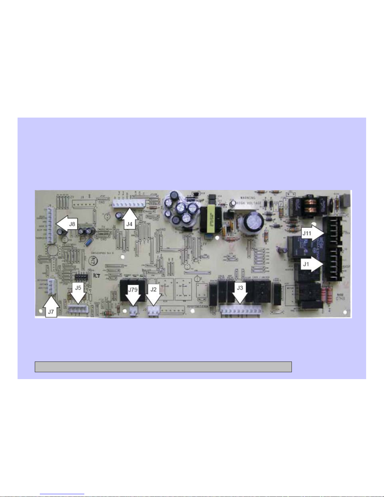
Power Supply Board (rear cover off)
CONFIDENTIAL AND PROPRIETARY INFORMATION-NOT FOR PUBLIC DISCLOSURE. September 2008
Page 13
13
Control Panel
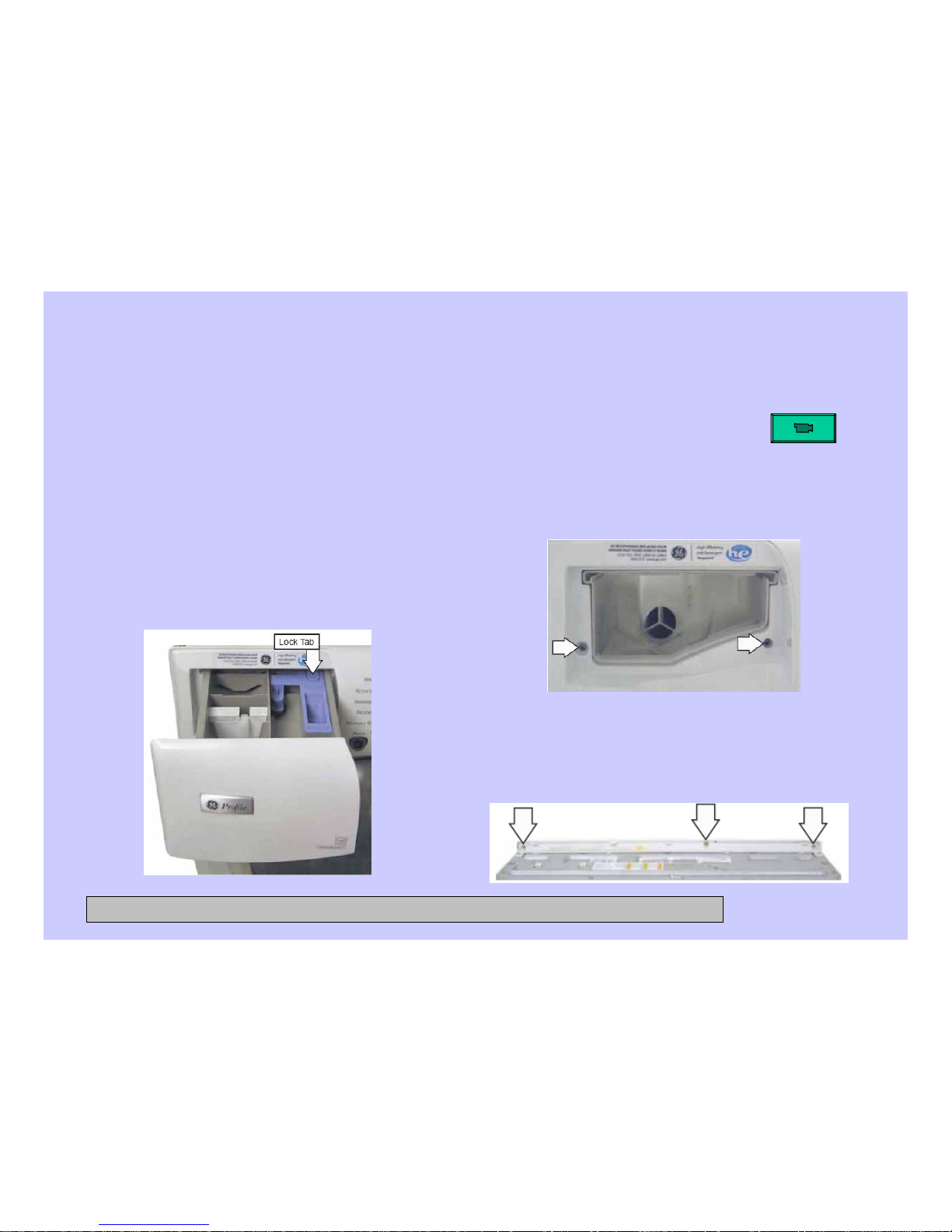
The control panel is held in place with 5 Phillips head screws and 1 tab.
To remove the control panel assembly:
1. Remove the top panel.
2. Pull the dispenser out to the stop
position. Press down on the lock tab.
Pull the dispenser out.
3. Remove the 2 Phillips-head
screws from the control panel
dispenser recess.
4. Remove the 3 (7-mm) hex-head
screws that attach the top of the
control panel to the control panel
brace.
CONFIDENTIAL AND PROPRIETARY INFORMATION-NOT FOR PUBLIC DISCLOSURE. September 2008
Page 14
14
Control Panel (cont.)
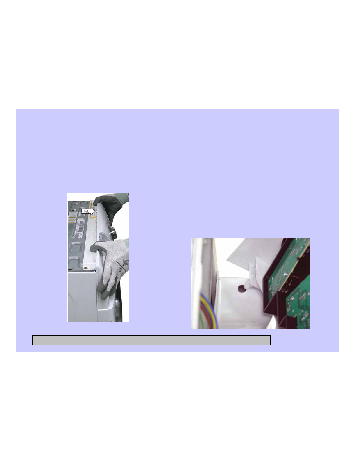
5. Lift the top edge of the panel to
disengage the tab that holds the top
of the panel in place.
6. Lift the panel from the cabinet.
7. Disconnect the wire harness from the
control panel.
Note: When installing the control panel,
place the panel pin in the locator hole
in the top right-side of the front panel
before engaging the tab.
CONFIDENTIAL AND PROPRIETARY INFORMATION-NOT FOR PUBLIC DISCLOSURE. September 2008
Page 15
15
Control Board
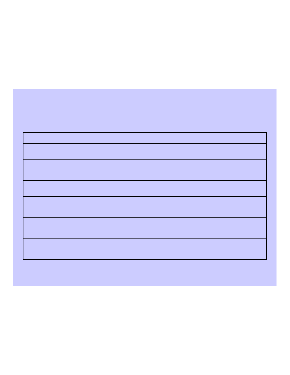
The control board detected a critical failure condition. Certain functions of the washer
will not operate. The VFD will show the fault code in the service test mode. The fault
code can only be removed in the service test mode. (See Service Test Mode.)
Fault
A cycle is completed. LEDs and VFD on the front panel stay on, all loads are turned
off. The door is unlocked. The control board remains in this mode until the door is
opened or after 2 hours have passed.
End of Cycle
The control is stopped by the user during the execution of a cycle. LEDs and VFD on
the front panel stay on. All loads are turned off. The door is unlocked. The control
board is ready to take user input to either modify, resume, or cancel the cycle.
Pause
The control board is executing the currently selected cycle. The door is locked.Run
A cycle is selected with the appropriate load selections and options. LEDs and VFD on
the front panel are on. The door is unlocked. The control board is ready to take user
input to either modify cycle selections or start a selected cycle.
Standby
No cycle is selected. All LEDs, VFD on front panel, load selections, and options are
off. The door is unlocked. The control board is ready to take input from user.
Idle
DescriptionMode Name
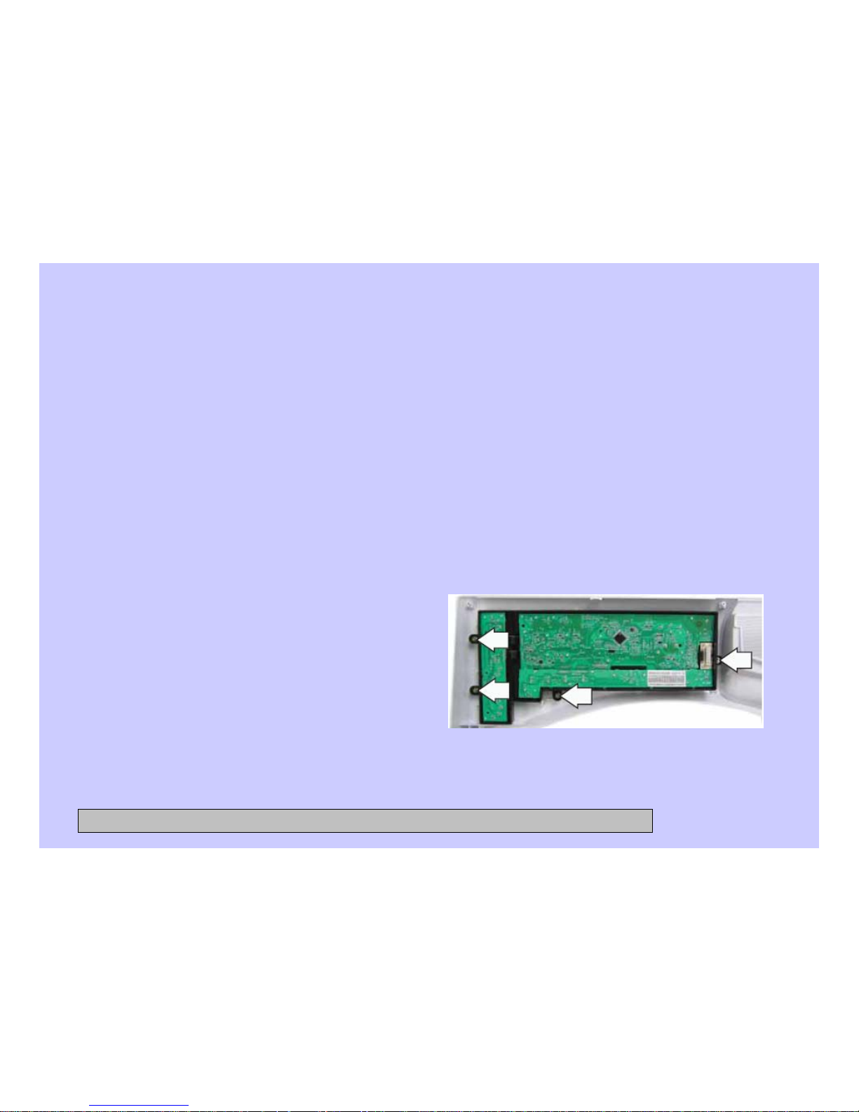
The control board is mounted in a housing that is attached to the inside of the control panel. The
control board and housing are replaced as an assembly. The control board assembly is held in
place by 4 (6-mm) hex-head screws. The control board is programmed to recognize 6 modes of
operation.
Operation of the control board can be checked by using the service test mode. (See Service Test
Mode.)Specific failures associated with the control board can initiate error codes E1, E2, E10, and E26.
(See Service Test Mode.)
Page 16
16
Remove the control board assembly:
1. Remove the control panel. (See 1. Control Panel.)
Note: In the following step, the knob is held in place by 4 plastic clips and may require
some effort to remove.
2. Remove the knob by pulling it straight out.
3. Remove the 4 (6-mm) hex-head screws that hold the control board assembly to
the control panel.
4. Remove the control board assembly
from the control panel.
5. Remove the cycle selection buttons.
CONFIDENTIAL AND PROPRIETARY INFORMATION-NOT FOR PUBLIC DISCLOSURE. September 2008
Page 17
17
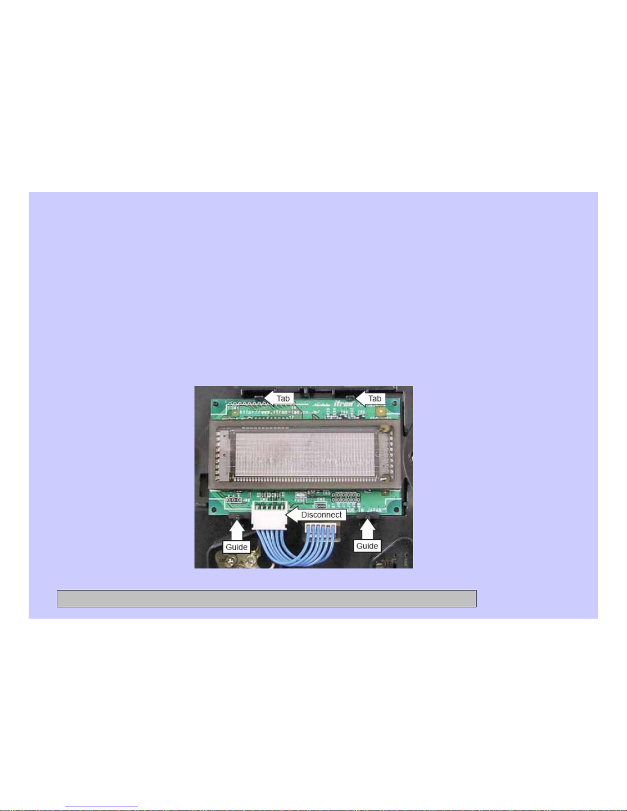
VFD (Vacuum Fluorescent Display)
To remove the VFD:
1. Remove the control panel. (See 1. Control Panel.)
2. Disconnect the wire harness from the VFD.
3. Press the 2 tabs that hold the VFD to the control panel, lift the VFD and remove
it from the 2 guides at the bottom.
CONFIDENTIAL AND PROPRIETARY INFORMATION-NOT FOR PUBLIC DISCLOSURE. September 2008
Page 18
18
Line Filter
The line filter helps to smooth out any fluctuations in voltage, protecting the control board
and providing more reliable operation. The line filter is installed on the interior side of the
rear panel, and is located left of the water valve.
To check the line filter, look for the outer surface to be burnt by heat or a power surge.
The filter resistance should be approximately 0 Ω between the black (top) wire terminals
and 0 Ω between the white (bottom) wire terminals.
To remove the line filter:
1. Remove the single black (top) and single white (bottom) wires.
2. Disconnect the wire harness by pressing the tab and pulling outward.
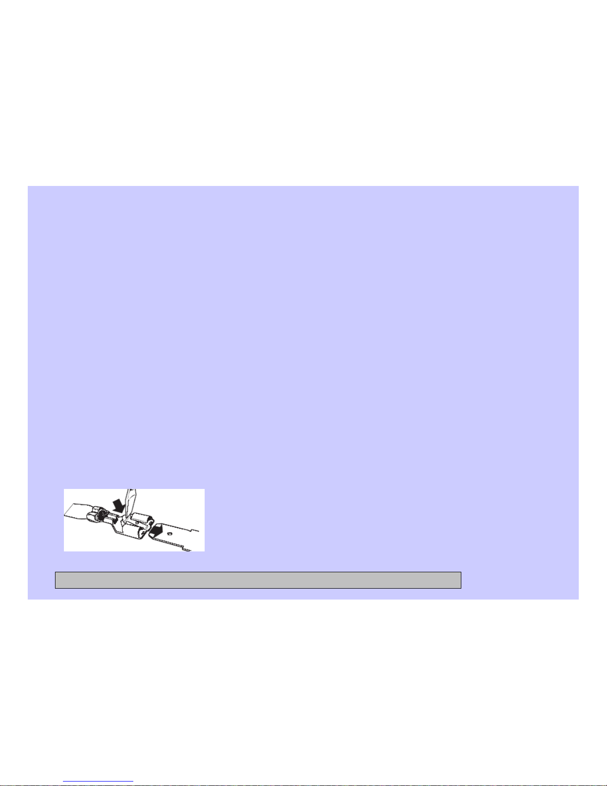
Note: The ground wires attached to the line filter use releasing locking tabs.
ELECTRICAL TERMINAL RELEASE/LOCKING TAB
CONFIDENTIAL AND PROPRIETARY INFORMATION-NOT FOR PUBLIC DISCLOSURE. September 2008
Page 19
19
Line Filter (cont.)
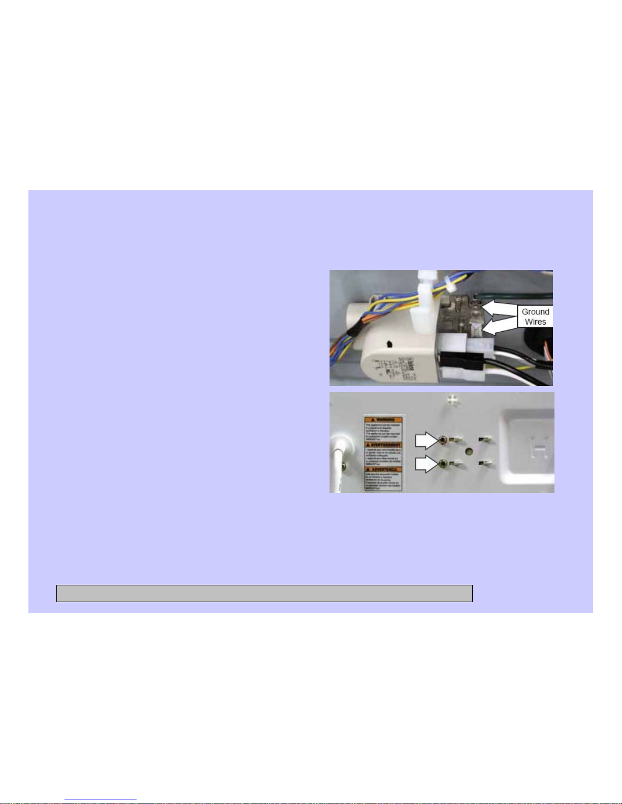
3. Press the locking tab on each
terminal and remove the 2
ground wires.
4. Remove the 2 (7-mm) hexhead screws that hold the filter
to the frame.
5. Move the filter to the right.
CONFIDENTIAL AND PROPRIETARY INFORMATION-NOT FOR PUBLIC DISCLOSURE. September 2008
Page 20

20
Door Lock
The door lock contains a door switch and solenoid operated locking and unlocking
mechanism.
The door locks when a cycle is entered (wake-up routine) and during every cycle. The
door unlocks at the completion of a cycle. The door will not open when:
The foam switch is open
Water temperature is above 130°F (54°C)
Wash basket is rotating
Specific failures associated with the door lock can initiate error codes E11 thru E13, and
E28. (See Service Test Mode.)
The door lock is held to the front panel with 3 Phillips-head screws. The door lock is
accessed from the front of the washer when the right side of the gasket is partially pulled
back.
CONFIDENTIAL AND PROPRIETARY INFORMATION-NOT FOR PUBLIC DISCLOSURE. September 2008
Page 21
21
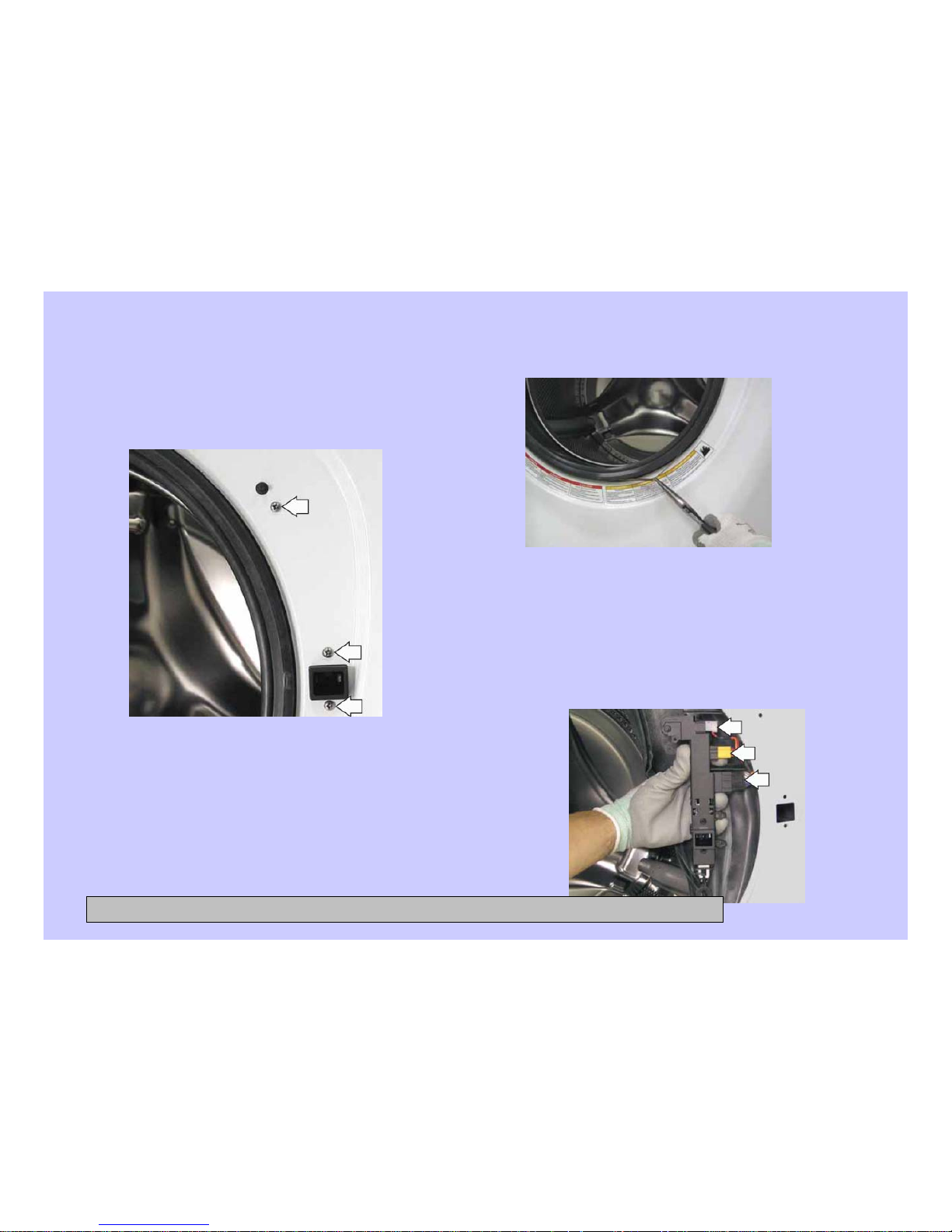
Remove the door lock
1. Open the door and remove the 3
Phillips-head screws that hold the door
lock to the front panel.
2. Use a long-nose pliers to grasp the
wire loop at the spring location and
expand it to clear the gasket.
3. Remove the spring and wire from the
gasket.
4. Pull the right side of the gasket away from
the front panel.
5. Pull the door lock to the opening and
remove the 3 wire harnesses.
Note: The door latch is solenoid-activated. It can remain
locked after power is removed.
CONFIDENTIAL AND PROPRIETARY INFORMATION-NOT FOR PUBLIC DISCLOSURE. September 2008
Page 22
22
Front Panel
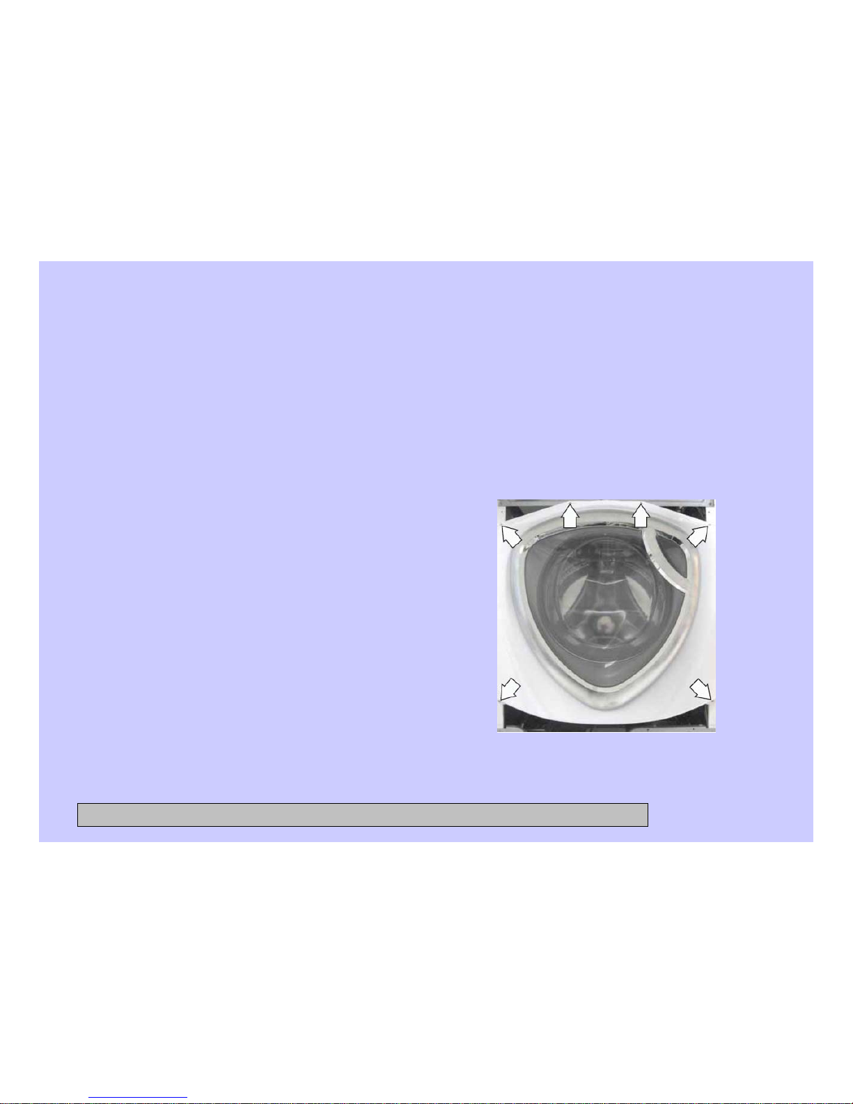
The front panel is hung on 2 hooks attached to the cabinet and held in place with four
1/4-in. hex-head and 2 Phillips-head screws. A gasket provides a watertight seal between
the front panel and outer tub. The front of the gasket is secured to the front panel flange
by a spring and wire located in the fold of the gasket. The door lock and wiring is
attached to the front panel.
To remove the front panel:
1. Remove the control panel. (See
Control Panel.)
2. Remove the service panel. (See
Service Panel.)
3. Open the door. Remove the 3 Phillipshead screws that hold the door lock to
the front panel. (See Door Lock.)
4. Remove the spring and wire from the
gasket. (See Door Lock.)
5. Position the gasket behind the front
panel door opening. Close the door.
6. Remove the four 7-mm hex-head and 2
Phillips-head screws that attach the
front panel to the cabinet.
7. Lift up then remove the front panel
from the 2 hooks.
CONFIDENTIAL AND PROPRIETARY INFORMATION-NOT FOR PUBLIC DISCLOSURE. September 2008
Page 23
23
Dispenser Assembly
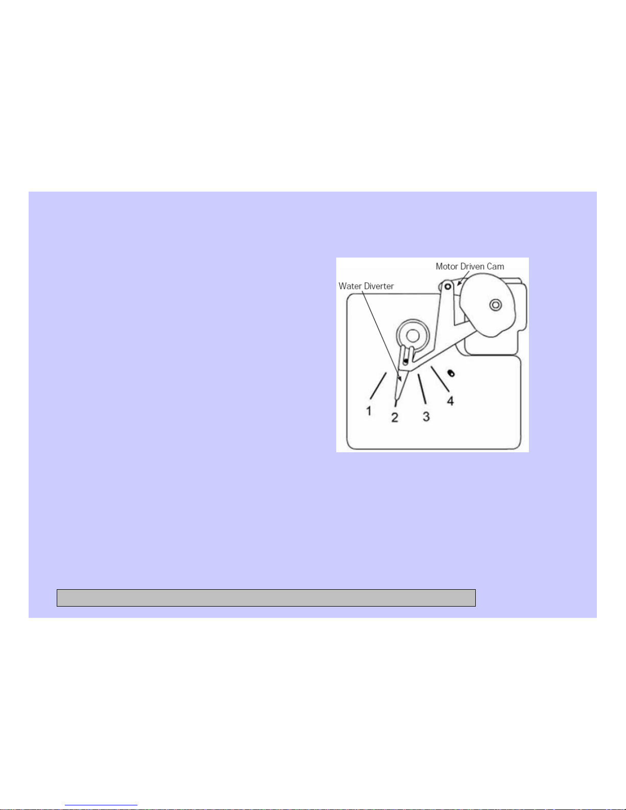
The dispenser assembly provides automatic
dispensing of detergent, bleach, and fabric
softener as long as the user fills the
compartments prior to starting the washer.
The products added to the dispenser are
diluted with water before they are dispensed
into the wash tub. This is accomplished by a
water diverter that sprays a controlled jet of
water into the proper compartment at the
correct time. The water diverter movement is
provided by a motor-driven cam located on
the dispenser tank. The diverter motor and
water valve are operated by the control
board.
At the start of a cycle, after the wake-up
routine is completed, the dispenser always
moves into position before fill takes place.
Dispenser Tank
Position Dispenser Function
1Pre Wash
2 Wash
3 Fabric Softener
4 Bleach
CONFIDENTIAL AND PROPRIETARY INFORMATION-NOT FOR PUBLIC DISCLOSURE. September 2008
Page 24

24
Dispenser Assembly (cont.)
Operation of the dispenser can be checked by using service test mode t15. (See
Service Test Mode.)
Specific failures associated with the dispenser can initiate error code E9. (See
Service Test Mode.)
Caution: When testing the diverter motor, DO NOT remove the wiring harness from
the diverter motor unless replacing the motor assembly. The motor assembly
has a special locking connector and the wiring harness will not stay reconnected
if removed and reinstalled on the same motor.
To remove the dispenser assembly:
1. Remove the top and control panels. (See 1. Top and Control Panels.)
2. Remove the gasket inlet hose from the clip attached to the dispenser.
CONFIDENTIAL AND PROPRIETARY INFORMATION-NOT FOR PUBLIC DISCLOSURE. September 2008
Page 25
25
Dispenser Assembly (cont.)
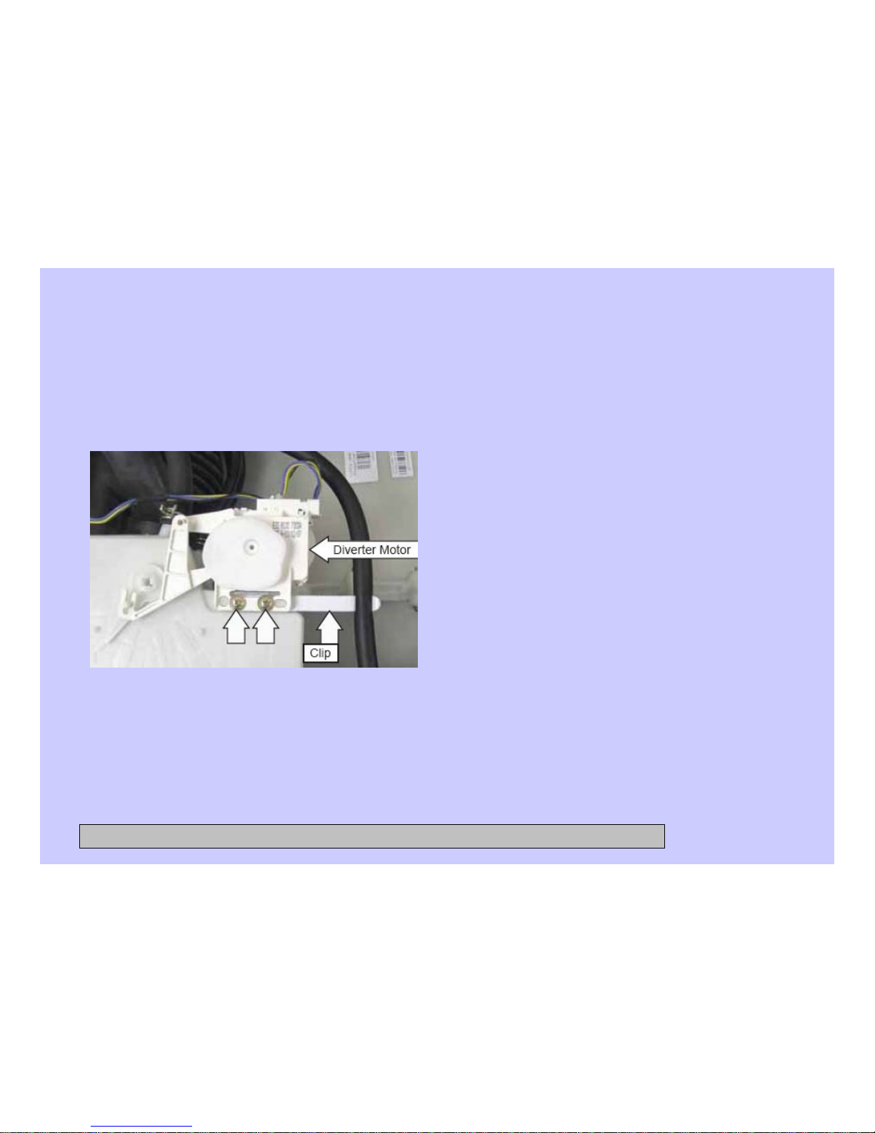
3. Remove the 2 Phillips-head screws
that attach the diverter motor and clip
to the dispenser tank. Place the
motor and clip aside.
4. Mark the positions of the 3 bulk
dispenser hoses connected to the
dispenser.
5. Remove the water inlet, tub vent,
and bulk dispenser inlet hoses from
the dispenser:
Note: The water inlet, tub vent, and bulk
dispenser inlet hoses are difficult to
remove.
a) Squeeze each clamp and slide it back.
b) Carefully break each hose loose by
inserting a small fl at blade screwdriver
under the hose to break the seal.
c) Remove the hoses.
CONFIDENTIAL AND PROPRIETARY INFORMATION-NOT FOR PUBLIC DISCLOSURE. September 2008
Page 26

26
Dispenser Motor
The dispenser is operated by a 120-VAC, 60-Hz motor. The dispenser motor receives
commands from the control board and controls dispenser operation.
Operation of the dispenser motor can be checked by using the Service Test Mode t12.
(See Service Test Mode.)
Specific failures associated with the dispenser motor can initiate error codes E38, E39,
and E62. (See Service Test Mode.)
To remove the dispenser motor:
Access the dispenser assembly. (See Dispenser Assembly.)
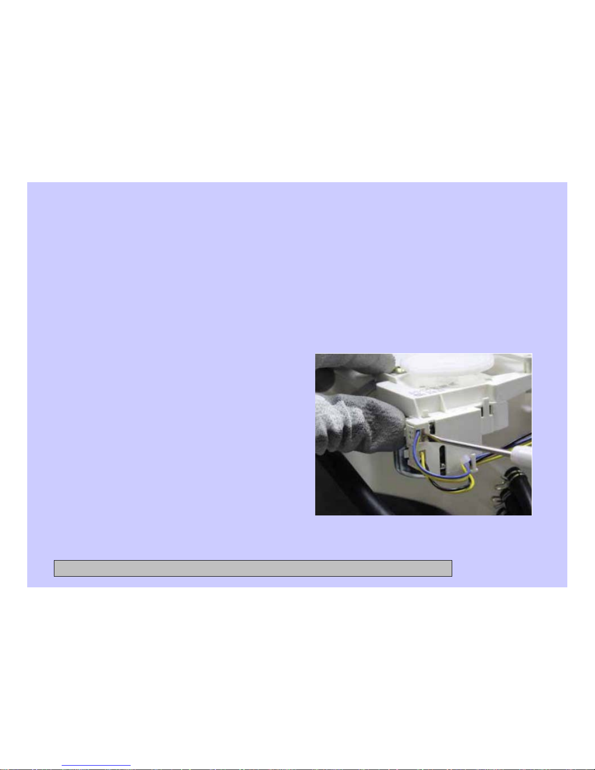
Caution: Lock tabs on the dispenser motor wiring harnesses are fragile. Tab breakage
can occur if excessive release pressure is applied.
Note: In the following step, it can be helpful to insert a small flat blade screwdriver (as
shown) to remove the wire harnesses.
CONFIDENTIAL AND PROPRIETARY INFORMATION-NOT FOR PUBLIC DISCLOSURE. September 2008
Page 27
27
Dispenser Motor (cont.)
1. Carefully press the lock tab and disconnect the 2 wire harnesses from the
dispenser motor.
Harness Removal
2. Remove the 2 Phillips-head screws
that attach the motor and gasket inlet
hose clip to the dispenser tank. (See
Dispenser Assembly.)
3. Lift the dispenser motor vertically
from the dispenser tank.
CONFIDENTIAL AND PROPRIETARY INFORMATION-NOT FOR PUBLIC DISCLOSURE. September 2008
Page 28
28
Power Board Assembly
To remove the power board assembly:
The power board and its cover are
replaced as an assembly.
1. Remove the top panel.
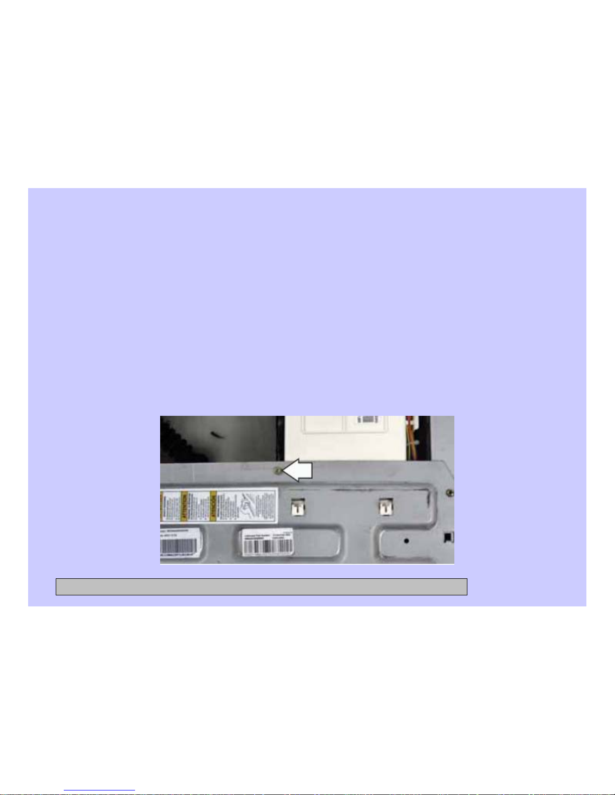
Note: The power supply assembly is attached to the control bracket with a 6-mm hex-
head screw and 2 tabs, and attached to the right side top brace with 1 locking tab.
2. Remove the 6-mm hex-head screw that attaches the power supply to the control
bracket.
CONFIDENTIAL AND PROPRIETARY INFORMATION-NOT FOR PUBLIC DISCLOSURE. September 2008
Page 29
29
Power Board Assembly (cont.)
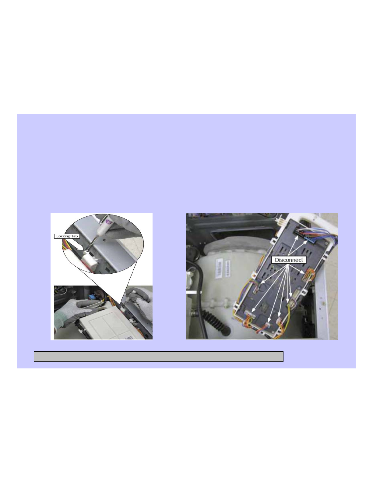
3. Using a small fl at blade
screwdriver, carefully pry the
locking tab away from the right side
top brace while pulling the power
supply up and towards the rear of
the washer.
4. Invert the power board.
5. Disconnect the wire harnesses from the
power board assembly.
CONFIDENTIAL AND PROPRIETARY INFORMATION-NOT FOR PUBLIC DISCLOSURE. September 2008
Page 30

30
Water Level Control
The water level control is installed on the cabinet right side top brace. The water level
control is connected by a hose to an air chamber attached to the bottom of the outer
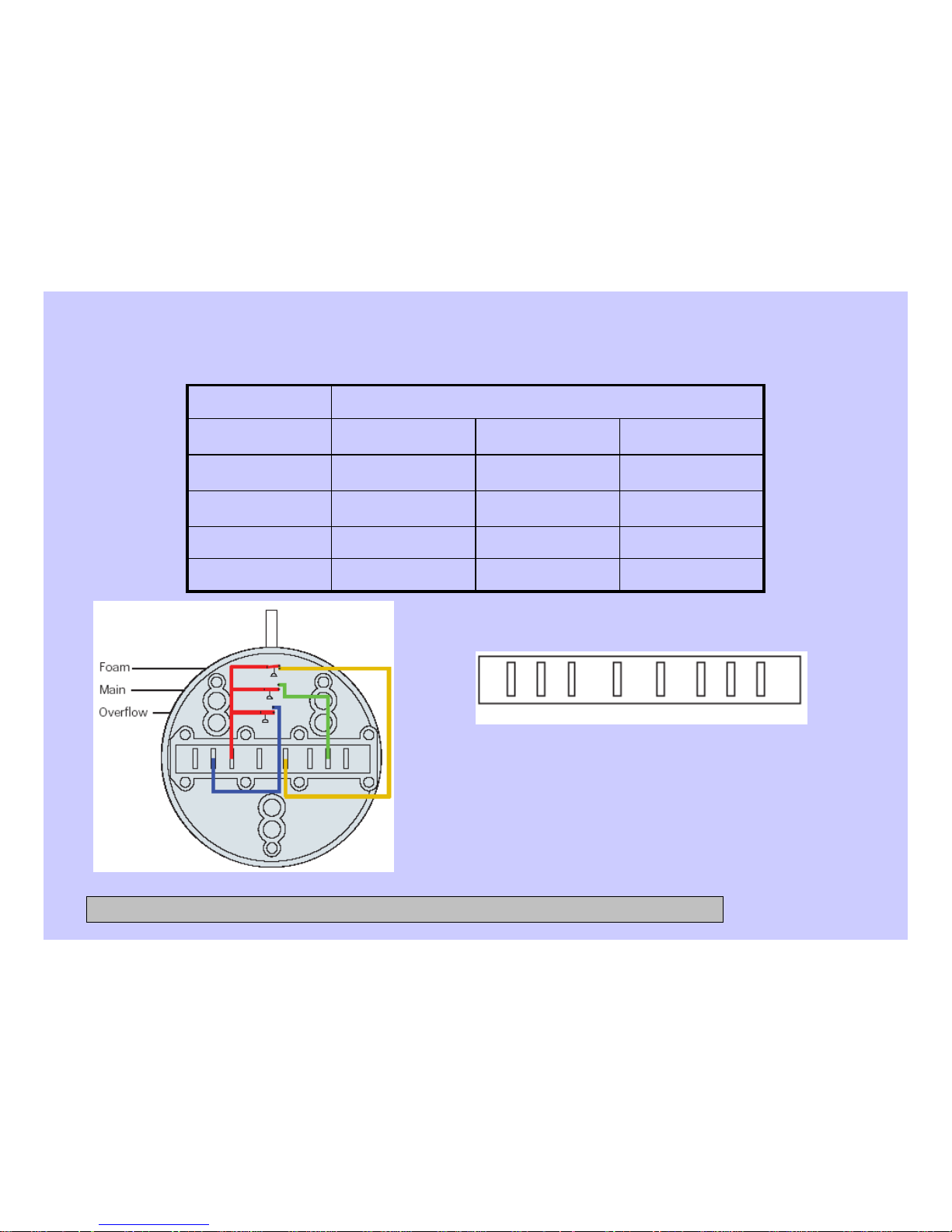
tub. The water level control consists of 3 internal switches that monitor 4 water level
conditions.
When the water level rises in the outer tub, air is trapped in the air chamber.
As the water level rises, the air pressure in the air chamber increases.
The increased pressure operates the 3 internal switches.
The washer has overflow protection and will automatically pump out regardless of
whether the washer is on or off, as long as the unit is plugged in. This action
supersedes all other commands.
The 3 internal switches are identified as foam, main, and overflow. The 4 water level
conditions monitored are empty, foam, main, and overflow.
CONFIDENTIAL AND PROPRIETARY INFORMATION-NOT FOR PUBLIC DISCLOSURE. September 2008
Page 31
31
Water Level Control (cont.)
ClosedClosed
OpenOverflow
OpenClosedOpenMain
OpenOpenOpenFoam
OpenOpenClosedEmpty
OverflowMainFoam
Switch PositionLevel
32 34 31 11 12 22 24 21
CONFIDENTIAL AND PROPRIETARY INFORMATION-NOT FOR PUBLIC DISCLOSURE. September 2008
Page 32
32
Water Level Control (cont.)
Water Level Control Operation
When the machine is empty, the foam
switch is closed and the motor circuit is
disabled. When the main wash cycle is
activated, the fill valve begins operating.
The machine fills to the foam water level,
the foam switch opens, and tumble begins.
Water temperature is read by the thermistor
and fill valve percentage of operation (water
tempering) is calculated for the main wash.
When calculated, and/or when the load
absorbs water, the tumbling will pause. Fill
will continue until the main water level is
reached (Adaptive fill), the main switch
closes, and main wash tumbling begins.
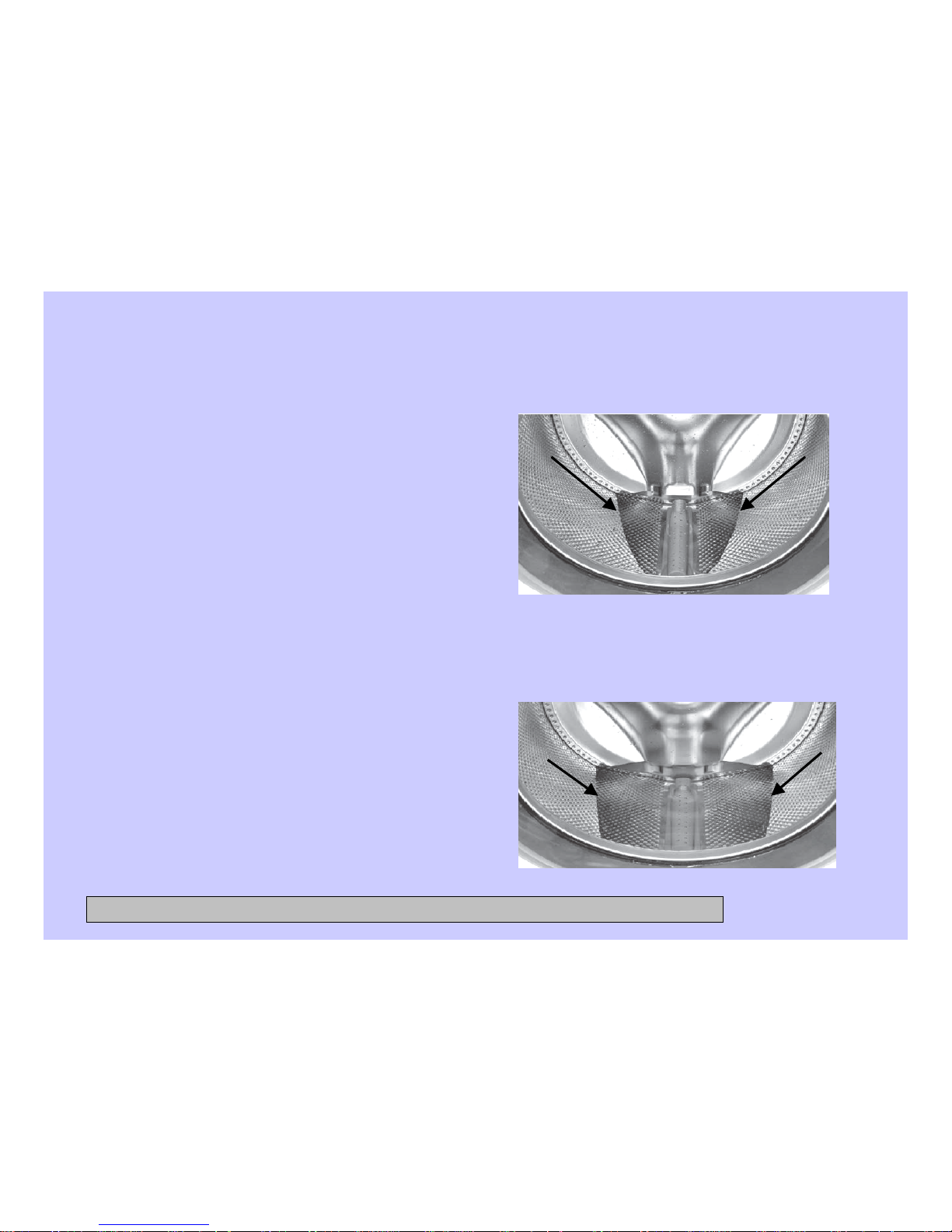
Water Levels
The foam water level, measured behind the
baffle, is approximately 1 3/4 -inches deep,
and approximately 1-inch deep measured at
the bottom center of the wash basket.
Foam Water Level
The main water level, measured behind the
baffle, is approximately 2 3/4 -inches deep,
and approximately 2- inches deep measured
at the bottom center of the wash basket.
Main Water Level
CONFIDENTIAL AND PROPRIETARY INFORMATION-NOT FOR PUBLIC DISCLOSURE. September 2008
Page 33
33
Water Level Control (cont.)
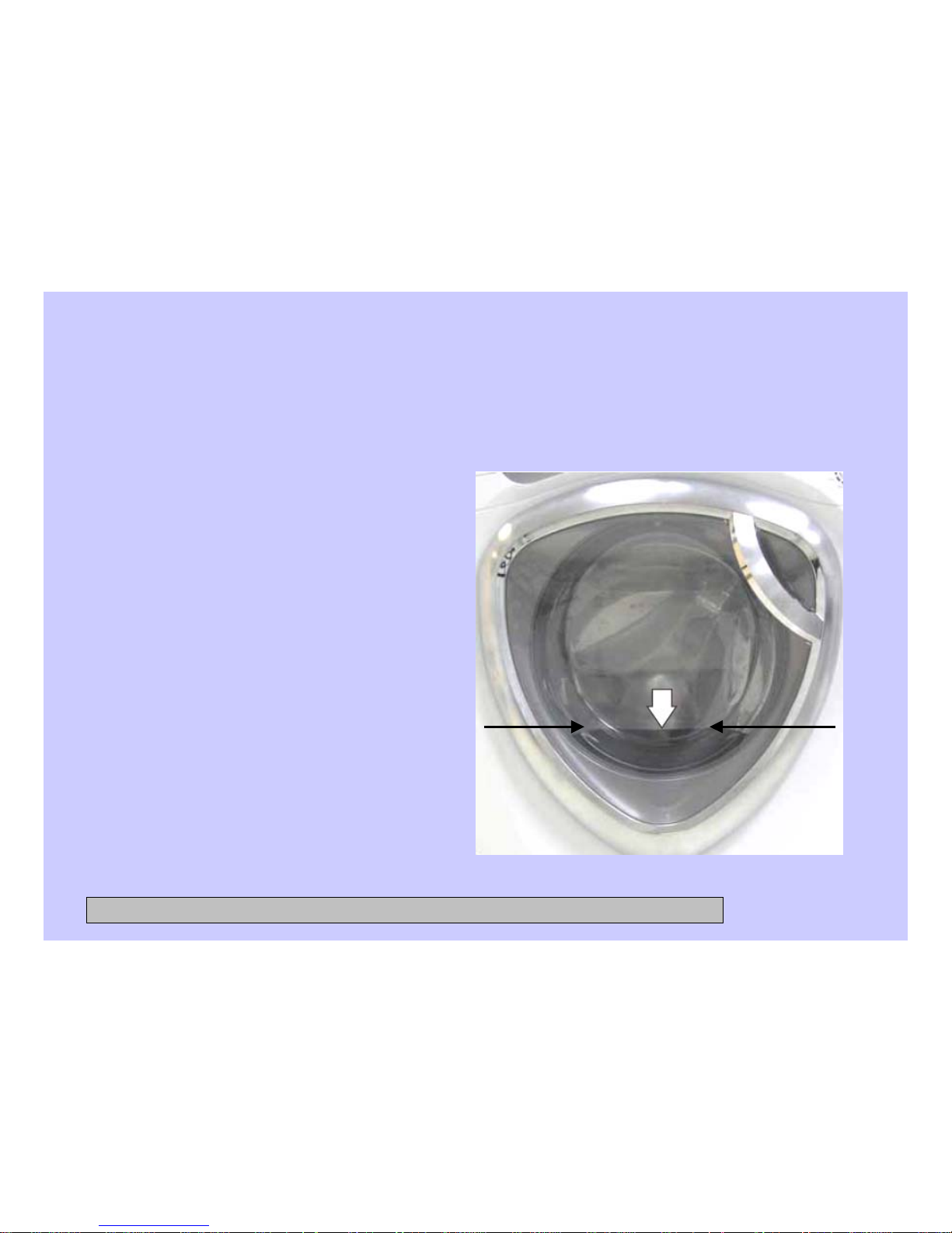
The overflow water level, measured at the
bottom center of the wash basket, is
approximately 7 ½ inches deep. Overflow
protection will occur at this water level.
Operation of the water level control can
be checked by using service test mode
t09. (See Service Test Mode.)
Specific failures associated with the water
level control can initiate error codes E6
and E14. (See Service Test Mode.)
Overflow Water Level
CONFIDENTIAL AND PROPRIETARY INFORMATION-NOT FOR PUBLIC DISCLOSURE. September 2008
Page 34
34
Water Valve
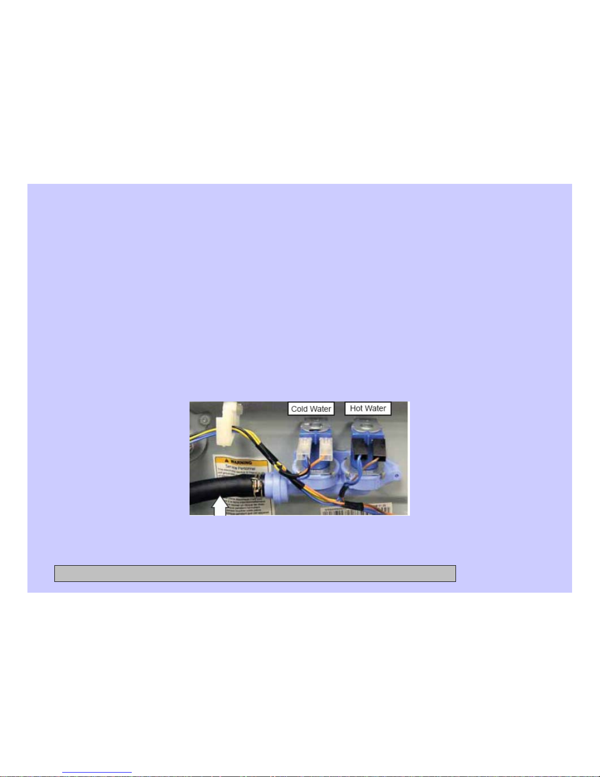
The water valve assembly consists of a valve body and two solenoid coils. The water
valve has a flow rate of 2.1 gallons (8 liters) per minute. It is inserted and retained in a
cutout in the rear of the cabinet and held in place by a single 6-mm hex-head screw. It
is only available as a complete assembly.
Each solenoid coil has an approximate resistance value of 1.1K Ω.
Operation of the water valve can be checked by using service test modes t11 and t12.
(See Service Test Mode.)
Specific failures associated with the water valve can initiate error code E7. (See Service
Test Mode.)
Outlet Hose
CONFIDENTIAL AND PROPRIETARY INFORMATION-NOT FOR PUBLIC DISCLOSURE. September 2008
Page 35

35
Pump
The pump consists of a 120-VAC, 60-Hz motor, impeller, impeller housing, and a
removable strainer that helps prevent foreign objects from entering the pump impeller
and drain outlet.
The pump runs whenever the washer is in the spin function of a cycle.
The pump runs if the water level control overflow switch is closed and the washer is
plugged in. (Overflow protection)
The pump is capable of eliminating 17 gallons (64 liters) per minute.
Recommended minimum standpipe diameter is 1 1/4 inches.
Standpipe maximum height is 96 inches, measured from the floor at the washer
location.
The pump motor has an approximate resistance value of 10.6 Ω.
Operation of the pump can be checked by using service test mode t08. (See Service
Test Mode.)
Specific failures associated with the pump can initiate error code E8. (See Service
Test Mode.)
CONFIDENTIAL AND PROPRIETARY INFORMATION-NOT FOR PUBLIC DISCLOSURE. September 2008
Page 36
36
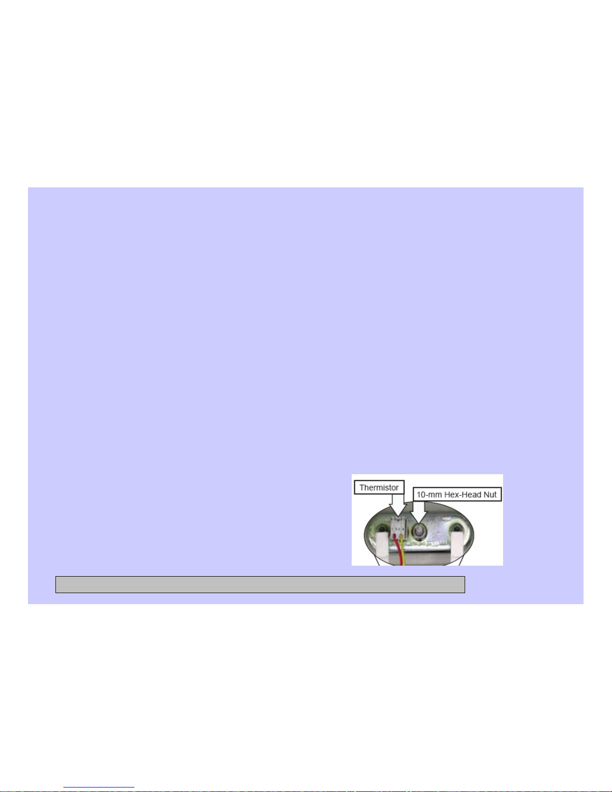
Heater Assembly
• The heater assembly consists of a heating
element and a water temperature thermistor.
• The heater can operate in • WHITES/HEAVY
DUTY, or STAIN INSPECTOR wash cycles,
and when the sanitize wash temperature is
selected.
• The heater assembly is held in place by a
bracket attached to the inside of the outer
tub and a 10-mm nut which compresses a
rubber gasket to the tub opening.
• When the 10-mm hex nut is tightened, it
squeezes the rubber gasket between 2
mounting plates to seal the heater assembly
to the opening of the tub.
• The hex nut is set from the factory at 31 in.
lbs of torque.
Operation of the heater assembly can be
checked by using service test mode t10.
(See Service Test Mode.)
Specific failures associated with the heater
assembly can initiate error codes E4 and E5.
(See Service Test Mode.)
Heating Element Specifications:
•120 VAC
•970 Watts
•Approximately 8 Amps
•Approximately 15 Ω
Thermistor Specifications:
•12 K • Ω at 75°F (24°C).
•Resistance goes down as temperature goes
up.
CONFIDENTIAL AND PROPRIETARY INFORMATION-NOT FOR PUBLIC DISCLOSURE. September 2008
Page 37

37
Inverter
The inverter receives commands from the control board and controls motor operation.
The inverter is enclosed in a protective housing and is located on the chassis,
under the left side of the outer tub. It is inserted in 2 guides at the rear and held in
place by a single Phillips-head screw at the front.
For the inverter to operate the motor correctly requires a supply voltage of 120 VAC, DC
input from the control board, and the three motor windings intact.
To check the inverter:
1. Remove the service panel. (See 1. Service Panel.)
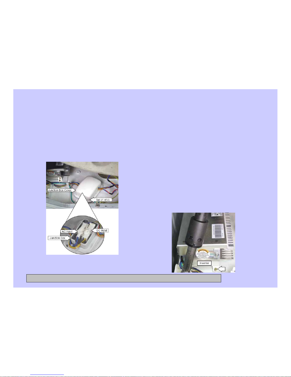
2. Press the 4 tabs inward and remove the junction box cover.
3. Enter test mode t04, t13, or t14.
4. Check for 120 VAC between the blue and red wires at the AC input harness.
Note: The 120 VAC inverter supply voltage is present only when the motor is supposed
to be operating.
CONFIDENTIAL AND PROPRIETARY INFORMATION-NOT FOR PUBLIC DISCLOSURE. September 2008
Page 38
38
Inverter (cont.)
5. Unplug washer, then check motor
resistance.
(See Motor Assembly.)
6. If 120 VAC is present at the AC
input harness and motor
resistance is correct, replace the
inverter.
Note: If the inverter overheats, the
washer will stop for 5 minutes.
Note
• The motor wire harness is soldered to the
inverter. Any fault in the inverter or motor
wire harness requires inverter
replacement.
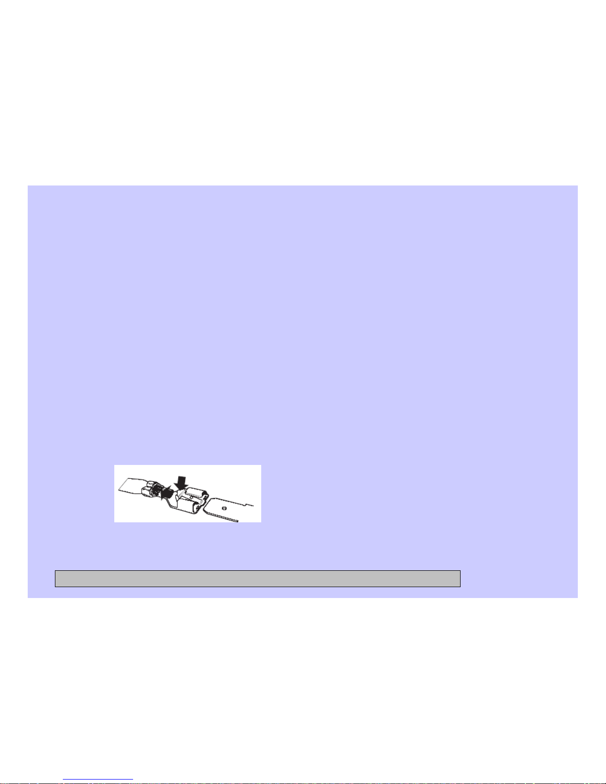
• The motor ground wire connector utilizes a
releasing locking tab.
ELECTRICAL TERMINAL
RELEASE/LOCKING TAB
CONFIDENTIAL AND PROPRIETARY INFORMATION-NOT FOR PUBLIC DISCLOSURE. September 2008
Page 39
39
Remove the inverter
1. Remove the service panel. (See
Service Panel.)
2. Press the 4 tabs inward and remove the
junction box cover.
3. Disconnect the AC and DC input wire
harnesses contained in the junction box.
5. Press the lock tab and remove the
motor ground wire.
6. Remove the plastic wire tie that holds
the motor wiring in place.
7. Remove the single Phillips-head screw
that holds the right front leg of the
inverter to the base pan.
8. Slide the inverter rearward to clear the
guides that hold the rear of the inverter
to the chassis.
9. Remove the inverter through the
enlarged opening on the left side of the
front frame.
4. Disconnect the motor wire harness
CONFIDENTIAL AND PROPRIETARY INFORMATION-NOT FOR PUBLIC DISCLOSURE. September 2008
Page 40

40
Motor Assembly
The motor assembly consists of a reversible, variable speed, 3-phase induction DC
motor, and sensor. The motor drives the tub drive pulley with a 7-rib belt.
The sensor monitors motor rpm and is connected to the control board. The motor
assembly is checked from the front of the washer and removed from the rear.
There are 2 methods to check the motor assembly.
Method A:
1. Remove the service panel. (See Service Panel.)
2. Disconnect the motor wire harness.
On the motor plug, check for an approximate resistance value of 6 ohms between
any two of the three wires:
Blue to white - 6 Ω
, Blue to red - 6 Ω, White to red - 6 Ω
The sensor has a resistance value of approximately 118 Ω between the two orange
wires.
Operation of the motor assembly can be checked by using service test modes t04,
t13, and t14. (See Service Test Mode.)
CONFIDENTIAL AND PROPRIETARY INFORMATION-NOT FOR PUBLIC DISCLOSURE. September 2008
Page 41
41
Motor Assembly (cont.)
Specific failures associated with the motor assembly can initiate error codes E3, and
E15 through E25. (See Service Test Mode.)
Method B:
1. Remove the service panel. (See Service Panel.)
2. Remove the single Phillips-head screw that holds the right front leg of the inverter to
the base pan.
3. Slide the inverter rearward to clear the guides that hold the rear of the inverter to the
base pan.
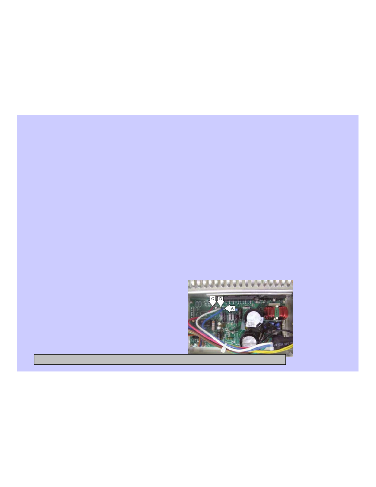
4. Position the inverter to access the inverter board.
5. On the inverter board, check for an approximate resistance value of 6 ohms between
any two of the three terminals:
• A to B (Blue to white) – 6 Ω
• A to C (Blue to red) - 6 Ω
• B to C (White to red) - 6 Ω
CONFIDENTIAL AND PROPRIETARY INFORMATION-NOT FOR PUBLIC DISCLOSURE. September 2008
Page 42
42
Motor Assembly (cont.)
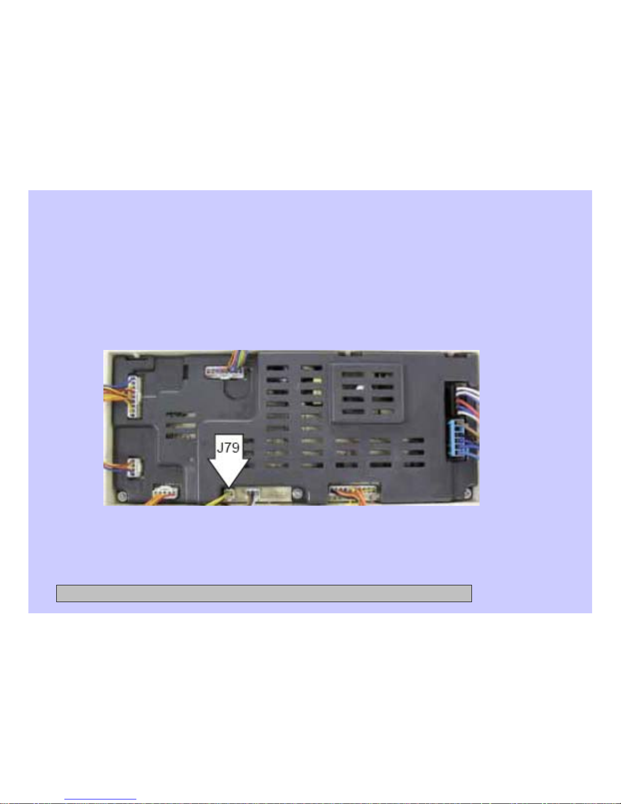
Note: The sensor and sensor wiring can be checked at the power board
assembly. Check for a resistance value of approximately 118 Ω resistance
between the 2 yellow wires located on the wire harness located at J79.
CONFIDENTIAL AND PROPRIETARY INFORMATION-NOT FOR PUBLIC DISCLOSURE. September 2008
Page 43
43
Door
To remove the door components:
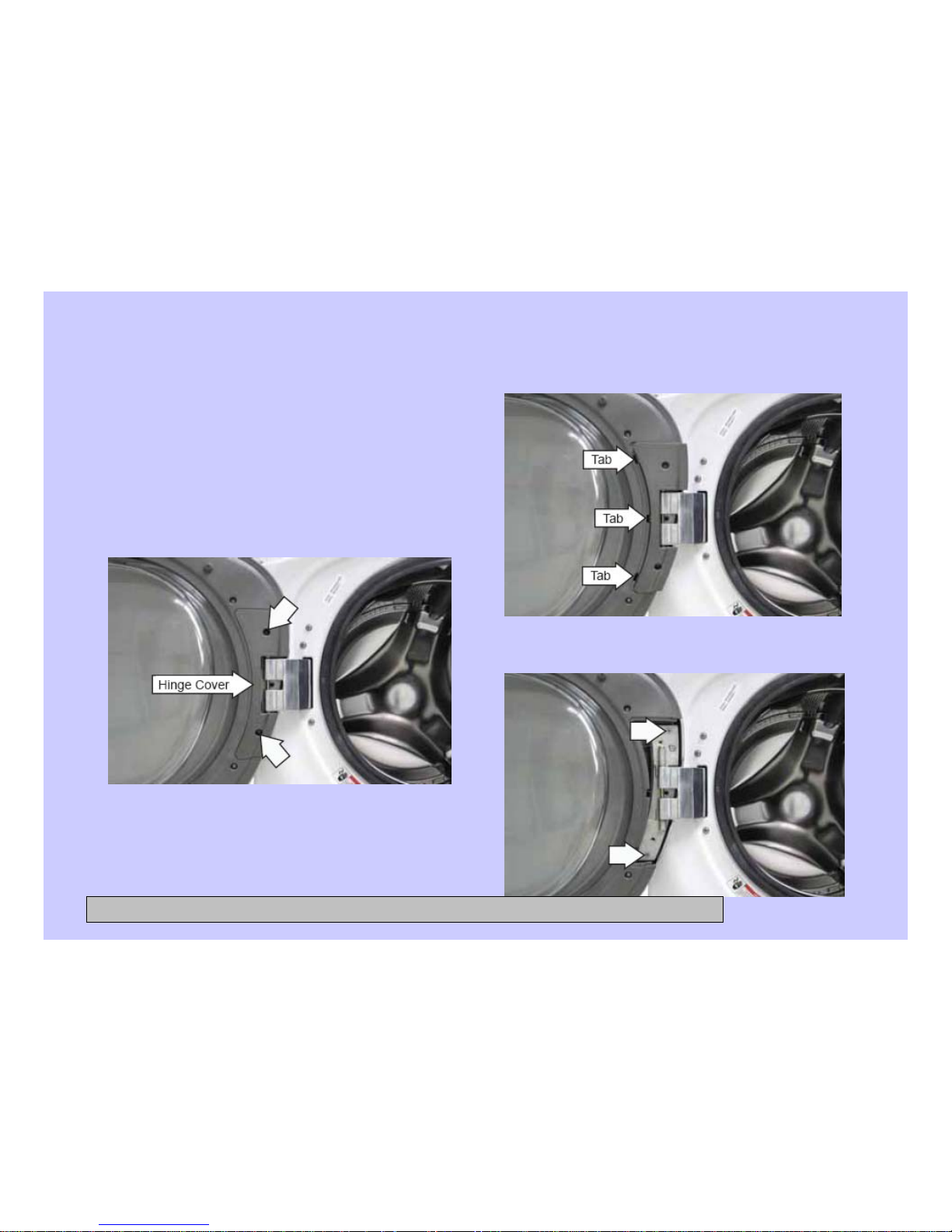
Note: The hinge cover is attached to the
door with 2 Phillips-head screws and
3 tabs located on the inside.
1. Remove the 2 Phillips-head screws.
2. Lift the right-side of the hinge
cover and slide it to the right.
3. Remove the 2 Phillips-head screws that
hold the door to the hinge door plate.
CONFIDENTIAL AND PROPRIETARY INFORMATION-NOT FOR PUBLIC DISCLOSURE. September 2008
Page 44
44
Door (cont.)
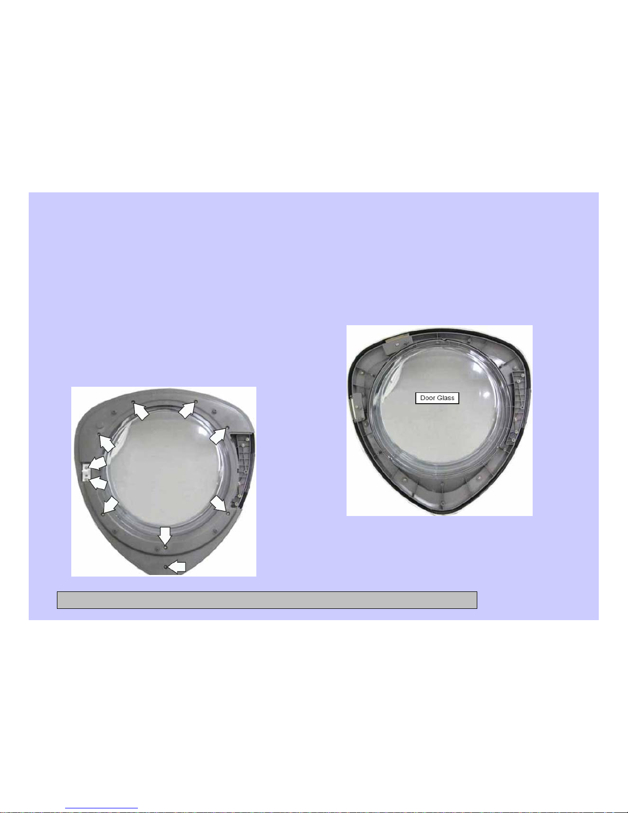
Note: Place the door on a soft, protected
flat surface so that the door glass
faces up. (The door should rest on the
handle side.)
4. Remove the 10 Phillips-head screws
that hold the door cover and door
strike to the door frame.
5. Lift and unsnap the door cover from the door
frame.
6. Lift the door glass out of the door frame.
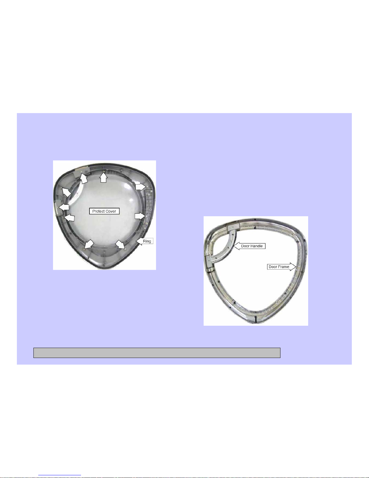
7. Remove the 9 Phillips-head screws
that attach the protect cover and ring to
the door frame.
CONFIDENTIAL AND PROPRIETARY INFORMATION-NOT FOR PUBLIC DISCLOSURE. September 2008
Page 45
45
Door (cont.)
8. Lift and remove the protect cover
and ring.
Note:
The door handle and door frame are
replaced as an assembly. (Part #
WH46X10210)
CONFIDENTIAL AND PROPRIETARY INFORMATION-NOT FOR PUBLIC DISCLOSURE. September 2008
Page 46
46
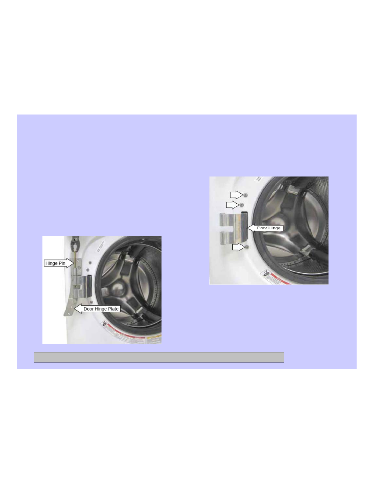
Door Hinge
To remove the door hinge:
1. Remove the door. (See Door.)
2. Grasp the hinge pin with a pair of
pliers and pull the pin out of the hinge.
Remove the door hinge plate.
Note: It may be helpful to drive the hinge
pin upward using a punch.
3. Remove the 3 Phillips-head screws that
hold the door hinge to the front panel.
4. Remove the gasket from the front panel.
5. Push and fold the left side of the gasket
inside the wash basket.
CONFIDENTIAL AND PROPRIETARY INFORMATION-NOT FOR PUBLIC DISCLOSURE. September 2008
Page 47
47
Door Hinge (cont.)
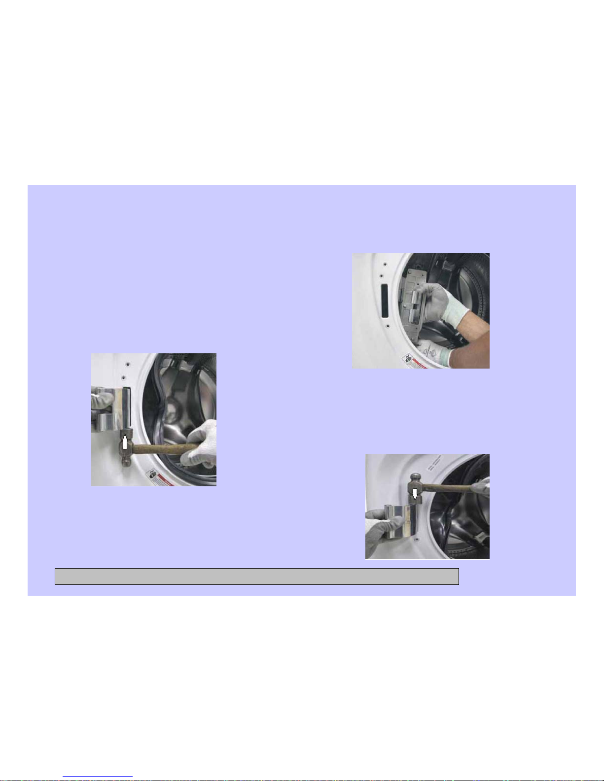
Note: The door hinge is attached to the
front panel with 3 Phillips-head screws in
front and 3 tabs on the back. After
removing the screws, it may be
necessary to strike the bottom of the
hinge (as shown) to free it from the front
panel.
6. Push the tub assembly back while
pressing the hinge arm inward and
carefully remove the door hinge
through the opening.
Note: When installing the hinge, it may be
necessary to strike the top of the hinge (as
shown) to fully engage the 3 tabs on the
rear of the front cover and to align the 3
screw holes in front.
CONFIDENTIAL AND PROPRIETARY INFORMATION-NOT FOR PUBLIC DISCLOSURE. September 2008
Page 48
48
Dampers
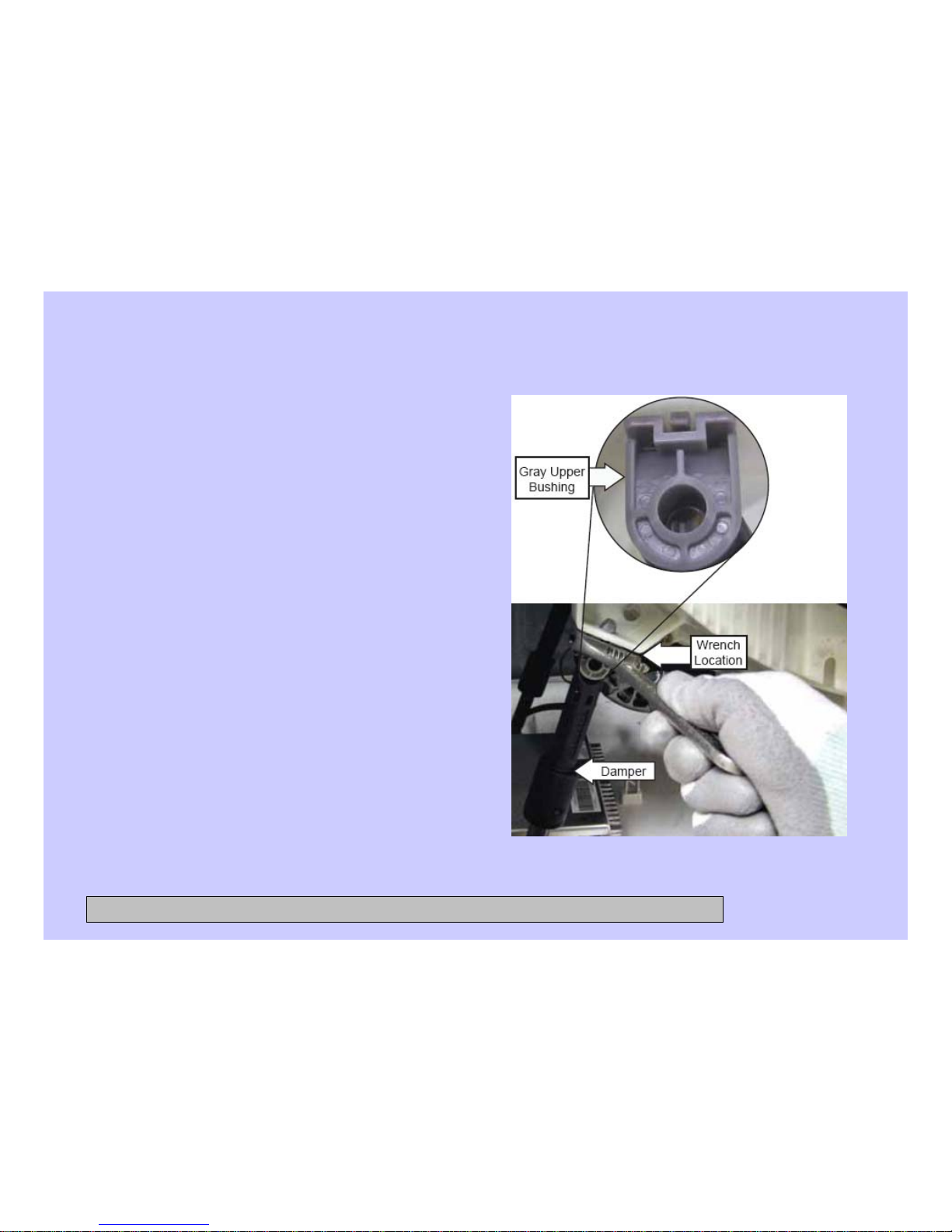
Each of the 4 dampers are secured to the
outer tub by a gray upper bushing
that locks in a slot in the outer tub.
Each damper is held to the chassis
with a plastic pin.
To remove the dampers:
Caution: Do not twist the damper
cylinder by hand to remove. Stress
may result in the damper developing
noise at a later date.
1. Remove the service panel.
2. Rotate the gray upper bushing a
quarter-turn clockwise (as viewed
from the top) using a 6-in. adjustable
crescent wrench with a jaw opening
of approximately 7/8 inch.
3. Compress and remove the damper
from the slot in the outer tub.
CONFIDENTIAL AND PROPRIETARY INFORMATION-NOT FOR PUBLIC DISCLOSURE. September 2008
Page 49
49
Dampers (cont.)
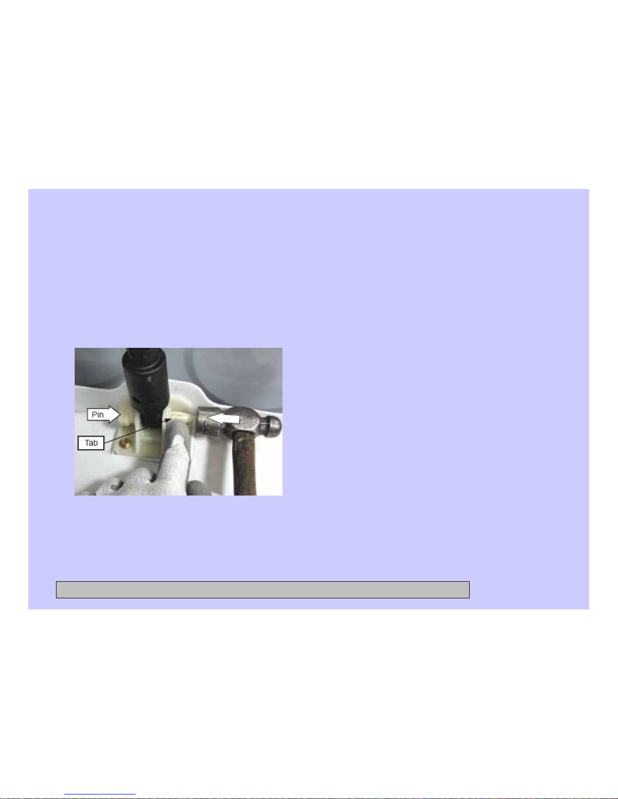
4. Remove the pin that secures each
damper to the chassis by pressing the
lock tab while pulling the pin out.
Note: It may be helpful to tap the pins out
with a small hammer while pressing on
the lock tabs.
To replace the dampers:
Note: The pin will be damaged when
removed from the chassis. Be sure to
install the new pin supplied with the
replacement damper.
1. Insert and fully seat the pin that secures
each damper to the chassis.
Note: It may be helpful to tap the pins into the
chassis with a small hammer.
2. Extend and fully insert the damper into
the slot in the outer tub.
3. Rotate the gray upper bushing a quarterturn counterclockwise (as viewed from
the top), using a 6-in. adjustable crescent
wrench with a jaw opening of
approximately 7/8 inch.
Note: Ensure the 2 lock tabs on the gray
upper bushing are in the square holes in the
outer tub.
CONFIDENTIAL AND PROPRIETARY INFORMATION-NOT FOR PUBLIC DISCLOSURE. September 2008
Page 50

50
Service Test Mode
The washer control has a service test mode that can be utilized by the service technician
in order to test critical components and to access error codes. This test mode will help the
service technician to quickly identify failed or improper operation of washer components.
Caution: Testing is accomplished through built-in test procedures. Unplugging
components for testing can damage component connections.
The washer must be in idle mode (blue screen is blank), before entering the test mode.
Idle mode occurs when the washer has completed a cycle. If the cycle is interrupted, the
washer will drain water when the power is re-applied. The water level switch must reset
BEFORE the test mode can be entered. If water remains in the washer, manually drain
the washer to reset the water level switch. A failed water level switch can cause an
inability to enter the test mode.
CONFIDENTIAL AND PROPRIETARY INFORMATION-NOT FOR PUBLIC DISCLOSURE. September 2008
Page 51
51
Service Test Mode (cont.)
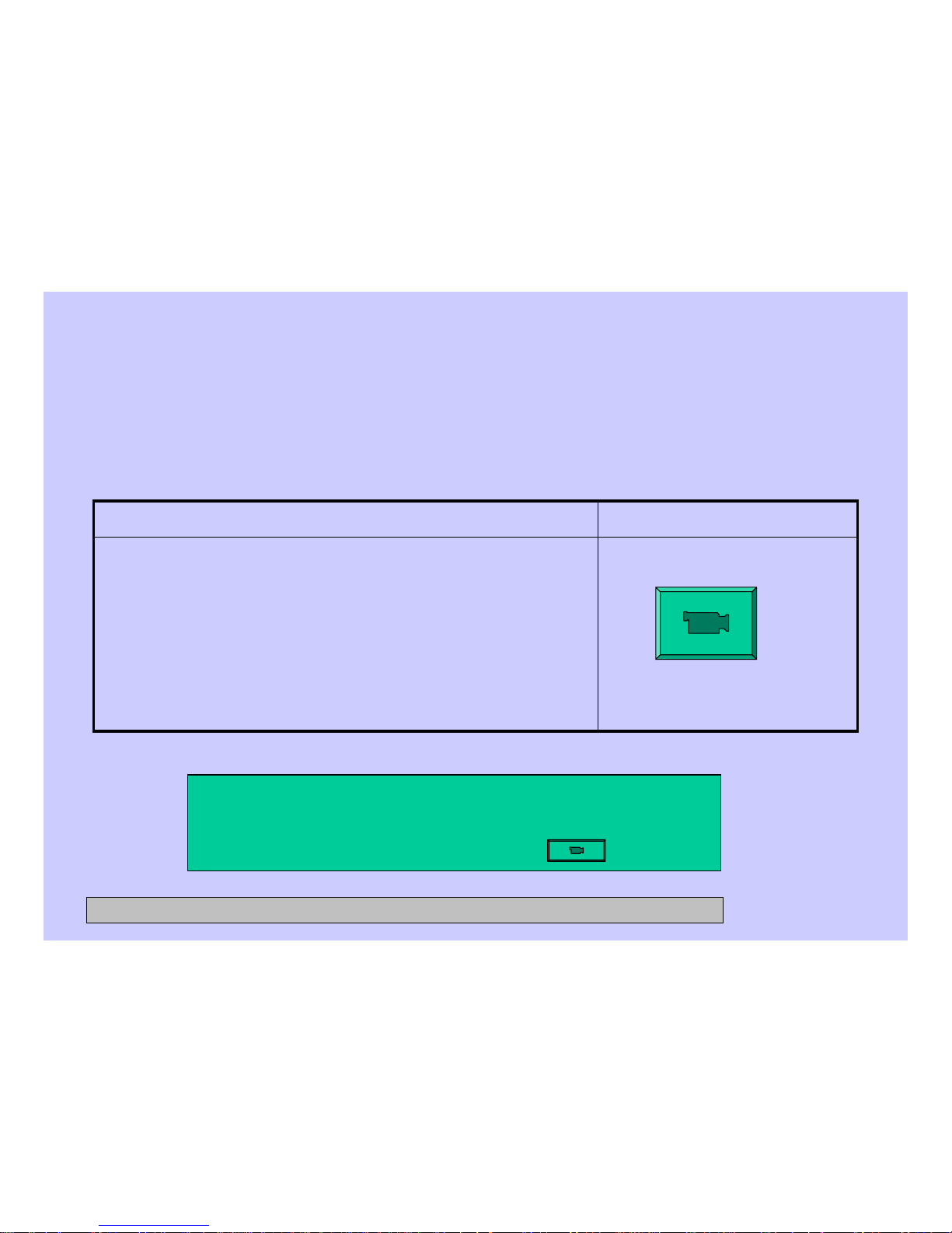
Press POWER button.1. Press POWER button to clear any current cycles.
Note: The display must be blank to proceed.
2. Press EXTRA RINSE-DELAY START-EXTRA RINSE-
DELAY START
A washer left in the test mode will exit the test mode
and unlock the door after approximately 30 minutes
To exit the test mode:To enter the test mode:
CONFIDENTIAL AND PROPRIETARY INFORMATION-NOT FOR PUBLIC DISCLOSURE. September 2008
Service Test Mode for Magellan Washer
Click here
Page 52
52
Service Test Mode (cont.)
Verifi es that each key operates correctly.t07 Key Continuity
Verifies all LEDs operate correctly.t06 UI Test
Checks the memory on the user interface control
board, then the memory on the Power Board.
t05 EEPROM Test
Tests the washer vibration by spinning to the extra
high spin speed as fast as possible. Note: No out
of balance detection will be performed here, so the
washer will spin up regardless of the out of balance
that is placed in the drum.
t04 Vibration Test
Checks the software version.t03 Version Information
Checks for any error codes reported by the controls.t02 Error Codes
Allows changing the configuration of the control for
different models.
t01 Configure UI (User
Interface)
DescriptionTest Mode
CONFIDENTIAL AND PROPRIETARY INFORMATION-NOT FOR PUBLIC DISCLOSURE. September 2008
Page 53
53
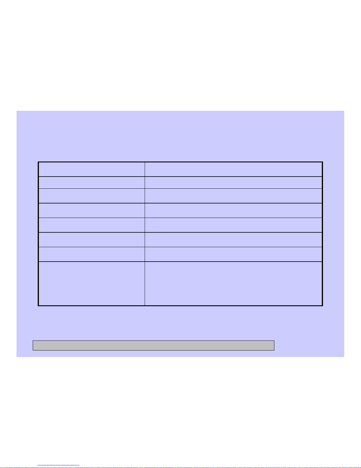
Service Test Mode (cont.)
Verifies washer spins. Note: No out-of-balance
detection will be performed here, so the washer will
spin up regardless of any out-of-balance condition
in the drum.
t14 Spin Test
Verifies washer tumbles (i.e., Wash Cycle).t13 Tumble Test
Verifies cold water valve turns on/off.t12 Cold Water Test
Verifies hot water valve turns on/off. t11 Hot Water Test
Verifies that both the Thermistor and Heater work.t10 Temp & Heater
Fills to all 3 levels; then pumps out water.t09 Water Level Sensor
Test drain pump.
t08 Pump Test
DescriptionTest Mode
CONFIDENTIAL AND PROPRIETARY INFORMATION-NOT FOR PUBLIC DISCLOSURE. September 2008
Page 54
54
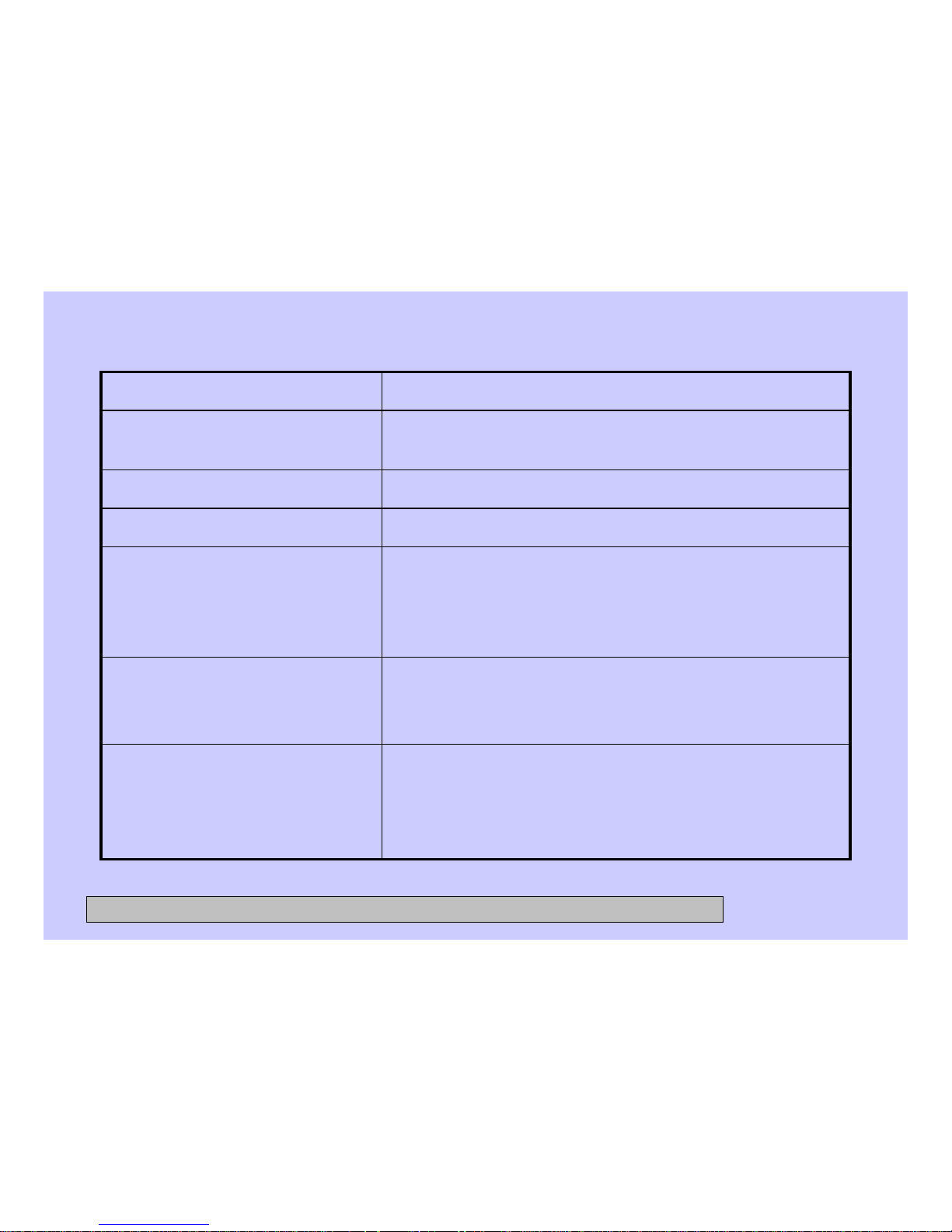
Service Test Mode (cont.)
Checks the control status of the prime status of the
pumps and allows the user to change/reset the
prime status.
t20 Bulk Primed Status
Manually initiates the priming of the Smart
Dispenser pumps.
t19 Bulk Manual Priming
Tests each spin speed of the washer. Note: No
out-of-balance detection will be performed here,
so the washer will spin up regardless of any out-of
balance condition in the drum.
t18 AutoSpin Profile
Verifies all the Smart Dispenser Sensors work.t17 Bulk Sensors Test
Verifies all the Smart Dispenser Pumps work.t16 Bulk Pumps Test
Verifies the dispenser motor works and can locate
all 4 dispenser positions.
t15 Dispenser Test
DescriptionTest Mode
CONFIDENTIAL AND PROPRIETARY INFORMATION-NOT FOR PUBLIC DISCLOSURE. September 2008
Page 55
55
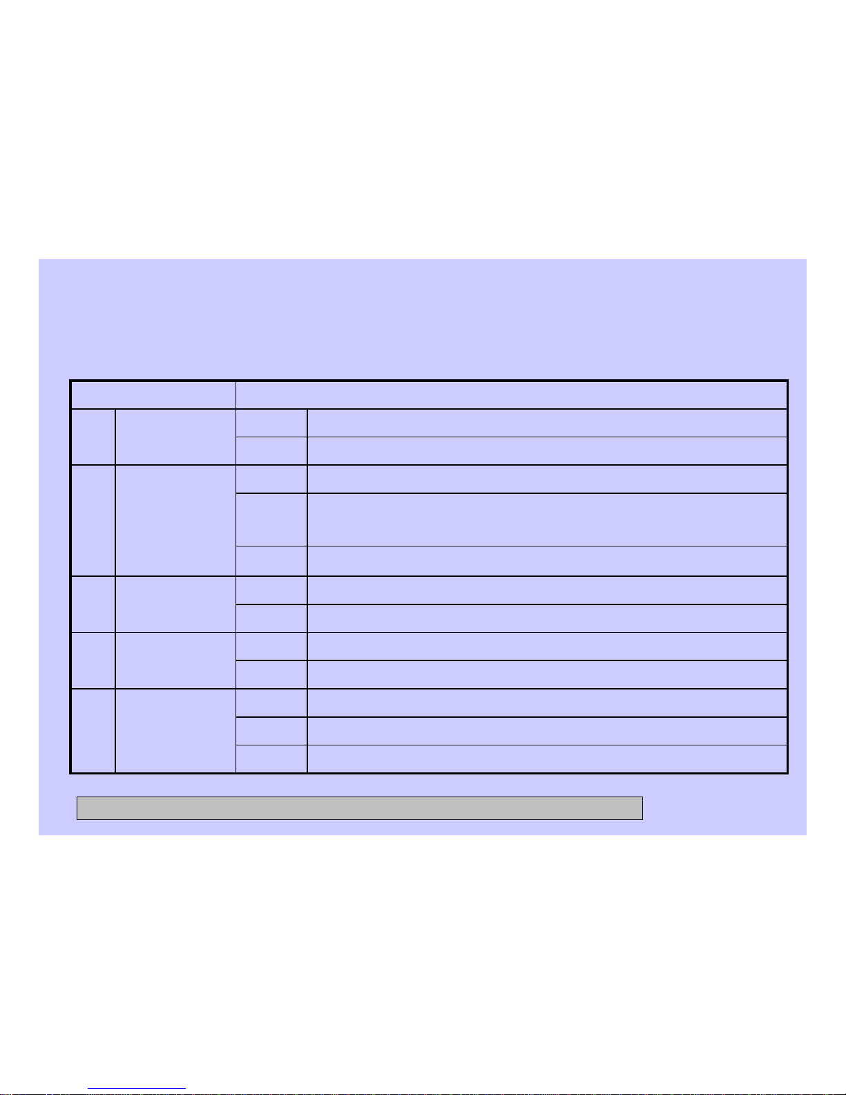
Diagnostic Tests
The following tables show the diagnostic tests and the button sequence that is required to perform them.
Returns to service mode screen
Displays PB status
Displays “test in progress” for a while; then displays UI Memory status
EEProm Test
t05
Interrupts and returns to service mode
Power
Spins up to 1300 rpm; then goes back to service mode screen
Enter
Vibration
Test
t04
Returns to service mode screen
Power
Displays the current version of software
Enter
Version Info
t03
Returns to service mode screenPower
Clears highlighted error code from machineStart/
Pause
Displays error codesEntert02
Returns to service mode screen
Power
Displays “configure UI”
EnterConfigure UIt01
SequenceService Mode Test
CONFIDENTIAL AND PROPRIETARY INFORMATION-NOT FOR PUBLIC DISCLOSURE. September 2008
Page 56
56
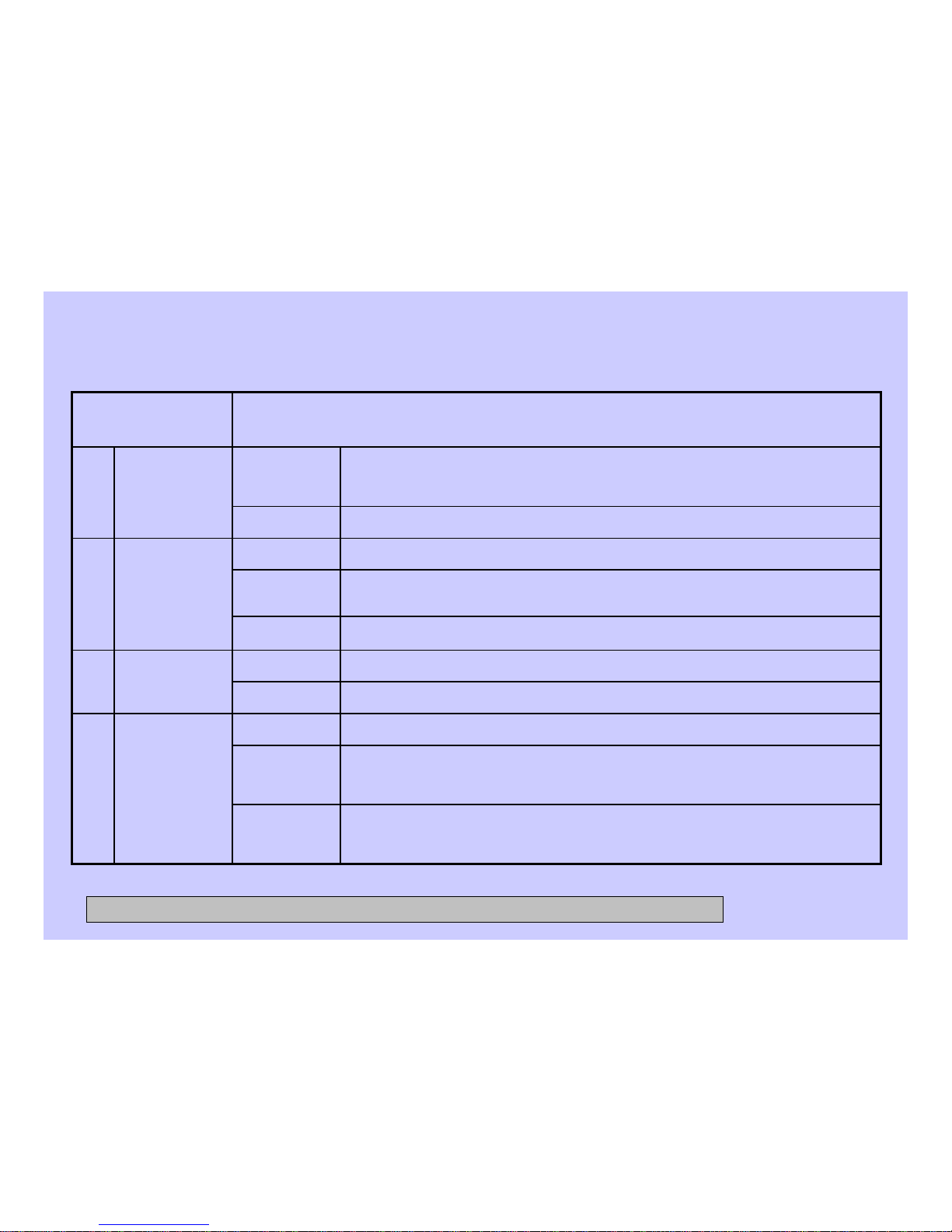
Diagnostic Tests (cont.)
Fills to normal level. Displays “Foam Level” until fi ll is complete, then
shows “Normal Wash Level”
Start
Fills to foam level. Displays “Tub Empty” until fi ll is complete;
then shows “Foam Level”
Start
Unit begins to drain. When draining is complete, displays “Tub Empty”
Enter
Water
Level
Sensor
t09
Interrupts draining and returns to service mode
Power
Begins running the drain pump
Enter
Pump Test
t08
Returns to service mode screenPower
Beep sounds as button is pressed
Any Button
but Power
Begins testingEnter
Key
Continuity
t07
Returns to service mode screen
Power
Lights up LEDs on the left side of UI and VFD; then lights up
the right side LEDs
EnterUI Test
t06
Sequence
Service Mode
Test
CONFIDENTIAL AND PROPRIETARY INFORMATION-NOT FOR PUBLIC DISCLOSURE. September 2008
Page 57
57
Diagnostic Tests (cont.)
Fills with cold water. Display shows “Cold Water On”
Enter
Cold Water
Valve Test
t12
Drains and returns to service mode screen
Start
t11
Hot Water
Valve Test
Returns to service mode screenPower
Unit tumbles
Enter
Tumble Test
t13
Drains and returns to service mode screen
Power
Fills with hot water. Display shows “Hot Water On”Enter
Drains and returns to service mode screenPower
Displays “baseline” and “current” temperature. Unit fi lls with
water and gets heated
Enter
Temp Sensor
and Heater
t10
Drains and returns to service mode
Power
Fills to overflow level. Display shows “Normal Wash Level”
until fill is complete. When overflow level is reached, the
pump begins to drain out the water.
Start
(cont.)t09
SequenceService Mode Test
CONFIDENTIAL AND PROPRIETARY INFORMATION-NOT FOR PUBLIC DISCLOSURE. September 2008
Page 58
58
Diagnostic Tests (cont.)
Repeats above sequence, starting with “pre-wash”Start
Dispenser
Test
t15
Displays “main detergent” and dispenser moves to position 2
Start
Displays “bleach” and dispenser moves to position 4
Start
Drains and returns to service mode screen
Power
Displays “fabric softener” and dispenser moves to position 3
Start
Displays “pre-wash” and dispenser moves to position 1
Enter
Ramps down and returns to service mode screen
Power
Ramps up to 1300 rpmStart
Ramps up to 1150 rpmStart
Ramps up to 1050 rpm
Start
Displays “estimated” and “current” rpm. Unit begins spinning at 410 rpmEnter
Spin Test
t14
Sequence
Service Mode Test
CONFIDENTIAL AND PROPRIETARY INFORMATION-NOT FOR PUBLIC DISCLOSURE. September 2008
Page 59
59
Diagnostic Tests (cont.)
Drains; then returns to service mode screen
Power
Begins priming selected, with water on to rinse it from dispenser
drawer
Enter
Displays “prime left detergent,” “prime softener,” prime right detergent”
with one highlighted
Enter
Bulk
Manual
Priming
t19
Interrupts and returns to service mode screen
Power
Slowly ramps up to 90, then 120, then 410
Enter
Auto Spin
Profile
t18
Returns to service mode screen
Power
Displays the status of Left Detergent, Softener and Right Detergent
Enter
Bulk Sensors
Test
t17
Drains and returns to service mode screen
Power
Continues cycling through the bulk pumpsStart
Displays “right det pump” and begins primingStart
Displays “softener pump” and begins priming
Start
Displays “left detergent pump”; water fills and primes left detergent
Enter
Bulk Pumps
Test
t16
Sequence
Service Mode Test
CONFIDENTIAL AND PROPRIETARY INFORMATION-NOT FOR PUBLIC DISCLOSURE. September 2008
Page 60
60
Diagnostic Tests (cont.)
Returns to service mode screen
Power
Returns back to “Bulk Primed Status”Enter
Displays “left det primed status”; choose status “yes” (lines
primed) or “no” (lines not primed)
Enter
Displays “left detergent pump,” “softener pump,” "right detergent
pump” with one highlighted
Enter
Bulk Primed
Status
t20
Sequence
Service Mode Test
CONFIDENTIAL AND PROPRIETARY INFORMATION-NOT FOR PUBLIC DISCLOSURE. September 2008
Page 61
61
Error Codes
NOTE: It’s important to note error codes should only be used to help identify components
which require testing. Never replace a part based solely on an error code. The control
can generate a false error if the right conditions exist. Use the code only as a reference
and always check the component before replacing.
•Check integrity of wiring and connections
between main control and Thermistor
Assembly.
•Using ohmmeter, measure Thermistor
resistance. If outside expected range, replace
Thermistor Assembly.
IF ABOVE STEPS DO NOT CLEAR THE
PROBLEM:
•Replace the main control.
Water Temperature
Sensor Problem
E4 Thermistor
Short
E5 Thermistor
Open
• Replace board as necessary.Internal problem
with UI or MC board
E1 UI EEPROM
E2 Power EEPROM
ActionDescriptionError Code
CONFIDENTIAL AND PROPRIETARY INFORMATION-NOT FOR PUBLIC DISCLOSURE. September 2008
Page 62
62
Error Codes (cont.)
•Ensure manual water valves are fully open.
•Check if water strainers on solenoid valve assembly
are clogged.
•Check for obstructions inside inlet water hoses.
•Ensure solenoid valves do not leak when the valves are
de-energized and the washer is powered down.
•Measure coil resistance for both valves. If outside
range (1000–1250 ohms at room temp.), replace
solenoid valve assembly.
IF ABOVE STEPS DO NOT CLEAR THE PROBLEM:
•Replace solenoid valve assembly.
Fill ProblemE7 Slow Fill
•Check integrity of wiring and connections between
main control and Water Level Sensor.
•Check integrity of Water Level Sensor; replace if
necessary.
•Check drain system.
IF ABOVE STEPS DO NOT CLEAR THE PROBLEM:
•Replace the main control.
Water Level Sensor
Problem
E6 Pressure
Switch
ActionDescriptionError Code
CONFIDENTIAL AND PROPRIETARY INFORMATION-NOT FOR PUBLIC DISCLOSURE. September 2008
Page 63
63
Error Codes (cont.)
•. Check for obstruction in dispenser mechanism and linkages.
•Check the electrical connections at the motor feedback switch
and in the harness.
•Check the electrical connections of water valves in the
harness.
IF ABOVE STEPS DO NOT CLEAR THE PROBLEM:
•Replace dispenser motor assembly.
Dispenser
Problem
E9
Dispenser
Motor
•Ensure pump strainer is clean and free of debris.
•Check for obstruction inside the drain hose.
•Check pump impeller blades and bearing; if evidence of blade
damage or seized bearings are present, replace the pump.
•Check the electrical connections at the pump motor and
harness.
•Measure pump motor resistance. If outside range (9–14 ohms
at room temp.), replace the pump.
Drain ProblemE8 Drain
System
ActionDescriptionError Code
CONFIDENTIAL AND PROPRIETARY INFORMATION-NOT FOR PUBLIC DISCLOSURE. September 2008
Page 64
64
Error Codes (cont.)
•Check integrity of wiring and connections between main
control and Door Lock mechanism.
•Investigate Door Lock mechanism; check door microswitch
operation, lock and unlock solenoid continuity and contact
integrity; replace Door Lock mechanism if necessary.
•IF ABOVE STEPS DO NOT CLEAR THE PROBLEM:
•Replace the main control.
Door Lock Assembly
Problems
E11 Door Lock
E12 Door Unlock
E13 Door Open
E28 Unexpected
Door Unlock
Detected
•Check integrity of wiring and connections between main
control and motor drive.
•Clear error code and run a cycle.
•If fault persists and reappears, replace the Machine Control.
Communication
Problem Between
Machine Control and
Motor Drive
E10 Motor
Communication
Interface
ActionDescriptionError Code
CONFIDENTIAL AND PROPRIETARY INFORMATION-NOT FOR PUBLIC DISCLOSURE. September 2008
Page 65
65
Error Codes (cont.)
Check integrity of wire connections between the Motor Drive
Control and the motor.
Clear fault and run cycle. If fault persists and reappears,
replace the motor drive.
Open circuit in
any of three
motor phases
detected
No speed info
present and
bridge will be
turned off
immediately
Motor will coast
down
Drive will
preserve nonzero speed info
during the stop
check stage
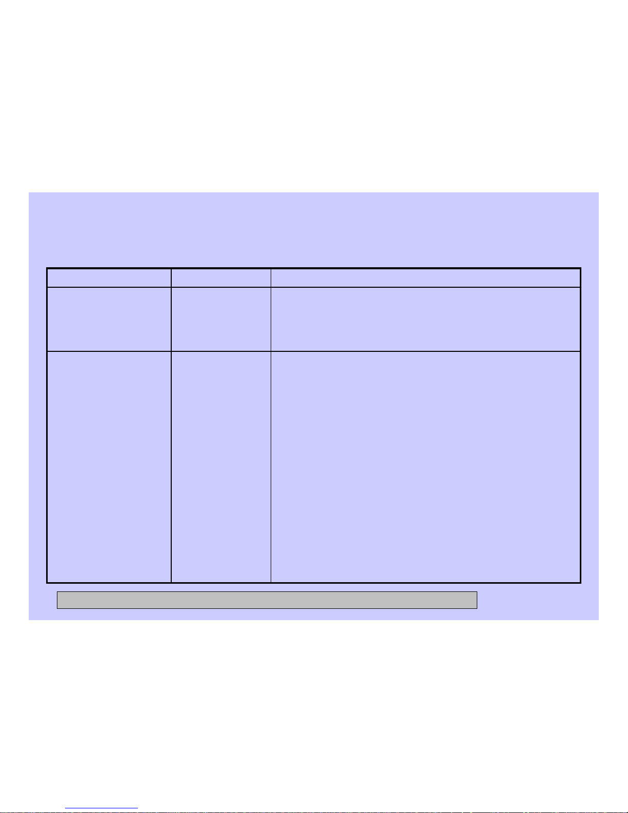
E15 Open Circuit
•Check valve for any signs of leaks.
•Check integrity of Water Level Sensor. Replace if
necessary.
Overflow level
was reached
E14 Overflow Error
ActionDescriptionError Code
CONFIDENTIAL AND PROPRIETARY INFORMATION-NOT FOR PUBLIC DISCLOSURE. September 2008
Page 66
66
Error Codes (cont.)
•Measure AC outlet voltage; ensure correct range (120V
to 132V AC).
•Check electrical connections at the motor drive.
•Check harness integrity between main control and motor
drive.
•Unplug the unit, wait 30 seconds and restart the unit.
•If the fault persists and reappears, replace the motor
drive.
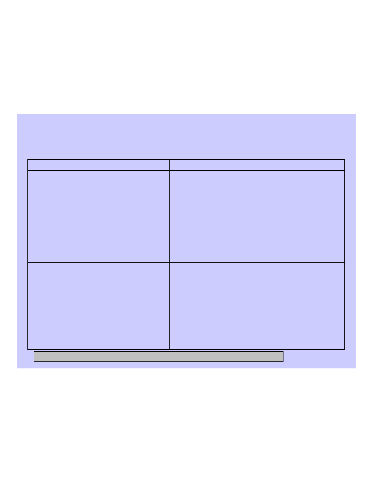
Motor Drive
Internal
Problems
E22 Over Volts
E23 Under Volts
E24 Under Volts
After Start
E25 Power Up
E3 Inverter EEPROM
Fault Event
E17 ADC Fault Event
•Ensure all 4 shipping bolts have been properly removed.
•Remove all foreign objects that may be lodged between
inner and outer baskets.
•Look for signs of seized bearing(s) on basket and drum
motor. Replace components as necessary.
•Inspect condition and mounting of door gasket. Replace
and re-mount as necessary.
•Ensure inner basket (drum) can rotate freely.
IF ABOVE STEPS DO NOT CLEAR THE PROBLEM:
•Replace motor drive or drum motor.
Motor Drive
operation above
design limits
E16 Over Trip
E18 Heatsink Over Temp
E19 Motor Over Temp
E20 Overload Current
E21 Overload Power
ActionDescriptionError Code
CONFIDENTIAL AND PROPRIETARY INFORMATION-NOT FOR PUBLIC DISCLOSURE. September 2008
Page 67
67
Error Codes (cont.)
•Check the integrity of the wiring between the Machine
Control Board and the User Interface.
•Clear the fault and run the cycle. If fault persists and
reappears, replace the Machine Control.
There is a
problem with the
Communication
between the
Machine Control
and the User
Interface Control
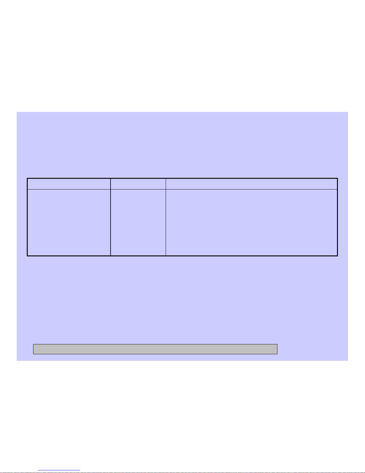
E26 LIN Comm Fail
ActionDescriptionError Code
CONFIDENTIAL AND PROPRIETARY INFORMATION-NOT FOR PUBLIC DISCLOSURE. September 2008
Page 68
68
CONFIDENTIAL AND PROPRIETARY INFORMATION-NOT FOR PUBLIC DISCLOSURE. September 2008
 Loading...