

GE Pro Elite 268-716-150-1248, Pro Elite 268-716-200-1248, Pro Elite 268-716-100-1044 Operation Manual
Pro Elite™ Professional Series
Water Treatment System by GE
Operation Manual
Pro Elite Analyzer

Table of Contents
Performance Data Sheet .............................................................................................................................................................3
How To Use This Manual .............................................................................................................................................................4
Safety Information ........................................................................................................................................................................4
Valve Layout ....................................................................................................................................................................................5
Analyzer Control Layout .............................................................................................................................................................5
System Specications 716 ..........................................................................................................................................................5
Location Selection ........................................................................................................................................................................6
Outdoor Locations ........................................................................................................................................................................6
System Features .............................................................................................................................................................................7
Equipment Installation ................................................................................................................................................................8
Water Line and Bypass Connections ................................................................................................................................... 11
Drain Line Connection .............................................................................................................................................................. 12
Regenerant Line Connections ............................................................................................................................................... 12
Overow Line Connection ...................................................................................................................................................... 13
Electrical Connection ................................................................................................................................................................ 13
System Operation ....................................................................................................................................................................... 14
Cycle Water Flows ....................................................................................................................................................................... 14
Camshaft Cycle Positions .........................................................................................................................................................15
Valve Disc Location/Function ................................................................................................................................................ 15
Disinfection of Water Conditioning Systems .................................................................................................................... 16
Displays, Icons and Cursors .....................................................................................................................................................17
Button Functions ........................................................................................................................................................................ 17
Programming Overview .......................................................................................................................................................... 18
Analyzer Control Operation ....................................................................................................................................................18
Level I Programming ................................................................................................................................................................. 18
Level l Programming - Analyzer Conditioner .................................................................................................................. 19
Level II Programming – P Values .......................................................................................................................................... 20
Programming the Lockout Feature ...................................................................................................................................... 20
Level lll Cycle Programming – C Values .............................................................................................................................. 21
Level IV Viewing History - H Values ...................................................................................................................................... 22
Program Reset ............................................................................................................................................................................. 22
Placing 268 Water Conditioning System Into Operation (Fill Brine Tank Last) ..................................................... 23
Placing 268r Water Conditioning System Into Operation (Fill Brine Tank First) ................................................... 24
The Water Conditioning System is Now Fully Operational. ......................................................................................... 25
Manual Regeneration Options .............................................................................................................................................. 26
Pro Elite Valve - Exploded View and Parts List .................................................................................................................. 27
Conditioner Tank and Regenerant Tank Assembly - Exploded View and Parts List ............................................ 29
Brine Well Assembly - Exploded View and Parts List ..................................................................................................... 31
Troubleshooting ......................................................................................................................................................................... 32
2
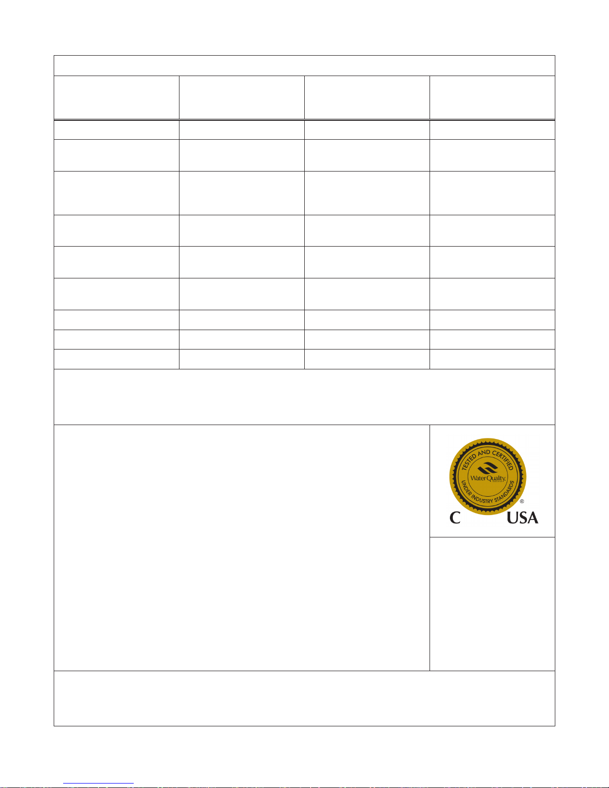
Performance Data Sheet
Pro Elite Analyzer Water Softener System Performance Data Sheet
Model Pro Elite
268-716-100-1044
Analyzer
Pro Elite
268-716-150-1248
Analyzer
Pro Elite
268-716-200-1248
Analyzer
Rated Service Flow (gpm) 8.0 13.0 15.0
Pressure Drop at Rated
Service Flow Rate (psi)
Rated Capacity
(grains @ lb of salt)
Rated Eciency
(grains/lb Salt @ lb of salt)
Maximum FLow Rate
During Regeneration (gpm)
10% Cross Linked Ion
Exchange Resin (cu ft)
4,033 grains/lb @ 3.3 lbs 4,045 grains/lb @ 4.95 lbs. 4,325 grains/lb @ 6.6 lbs
5.5 9.5 14.4
13,309 @ 3.3 lbs
26,327 @ 9.0 lbs
31,682 @ 15.0 lbs
20,023 @4.95 lbs
39,609 @ 13.5 lbs
47,665 @ 22.5 lbs
5.5 5.5 5.5
1.0 1.5 2.0
28, 548 @ 6.6 lbs
56,472 @ 18.0 lbs
67,958 @ 30.0 lbs
Tank Size 10" x 44" 12" x 48" 12" x 48"
Backwash - GPM 2.7 3.9 3.9
Rapid Rinse/Purge - GPM 5.5 5.5 5.5
Operating Pressure: 20-125 psi or 1.4-8.8 kg/cm2, Operating Temperature: 34-110°F or 1.1-43.3°C
Acceptable Salt Type: Sodium Chloride - Pellet salt
All Systems above tested at 35 psi ±5 psi, pH of 7.5 ±0.5, Capacity Testing Flow Rate = 50% of the rated service ow
rate for the various size systems.
These water softener systems have been tested by WQA and conform to NSF/ANSI 44 for specic
performance claims as veried and substantiated by test data. The rated salt eciencies above were also
determined in accordance with NSF/ANSI 44 and are only valid at the salt dosage referenced above. An
eciency rated water softener is a demand initiated regeneration (DIR) softener which also complies with
specic performance specications intended to minimize the amount of regenerant brine and water used
in its operation. Eciency rated water softeners shall have a rated salt eciency of not less that 3350
grains of total hardness exchanged per pound of salt (based on NaCl equivalency) (477 grams of total
hardness exchanged per kilogram of salt), and shall not deliver more salt than its listed rating. The rated
eciency of the water softener, the salt dosage at that eciency, the capacity at that salt dosage and
that of the eciency is only valid at the stated salt dosage. Eciency is measured by a laboratory test
described in NSF/ANSI 44. The test represents the maximum possible eciency the system can achieve.
Operational eciency is the actual eciency achieved after the system has been installed. It is typically
less than the eciency due to individual application factors including water hardness, water usage, and
other contaminants that reduce the water softener’s capacity. These systems are not intended to be used
for treating water that is microbiologically unsafe or of unknown quality without adequate disinfection
before or after the system. Refer to the system Installation and Service Manals for set-up and programming
instructions.
Contact your local dealer for parts and service. See your owner’s manual for warranty information.
Iowa Requirement:
Seller: _________________________________________ Date: ______________________
Buyer: _________________________________________ Date: ______________________
12/4/13
Tested and Certied by
the WQA to NSF/ANSI
Standard 44 & 372 for
softener performance &
lead free compliance and
CSA B483.1.
PENTAIR Residential Filtration, LLC
5730 North Glen Park Road
Milwaukee, Wisconsin 53209
PHONE: (262) 238-4400
3
How To Use This Manual
This installation manual is designed to guide the installer
through the process of installing and starting water
conditioning systems featuring Pro Elite equipment.
This manual is a reference and will not include every
system installation situation. The person installing this
equipment should have:
• Training in the Pro Elite Demand systems.
• Knowledge of water conditioning and how to
determine proper control settings.
• Adequate plumbing skills and qualications per local
and state laws, codes, and ordinances.
Icons That Appear In This Manual
not use an O-ring seal. Do not use pipe dope type
sealants on the valve body. Do not use pliers or
pipe wrenches.
• Do not use petroleum-based lubricants such as
Vaseline, oils, or hydrocarbon-based lubricants. Use
only 100% silicone lubricants.
• Use only the power transformer supplied with this
water conditioning system.
• All electrical connections must be completed
according to local codes.
• The power outlet must be grounded.
Install an appropriate grounding strap across the inlet and
outlet piping of the water conditioning system to ensure
that a proper ground is maintained.
WARNING: Failure to follow this
instruction can result in personal injury or
Note: Helpful hint to simplify procedure.
damage to the equipment.
Safety Information
• Observe all warnings that appear in this manual.
• Please review the entire Installation and Operation
Manual before installing the water conditioning
system.
• As with all plumbing projects, it is recommended
that a trained professional water treatment dealer
install the water conditioning system. Please follow
all local plumbing codes for installing this water
conditioning system.
WARNING: Excessive Weight Hazard. Use
two or more people to move and install
• System is not intended to be used for treating water
that is microbiologically unsafe or of unknown
quality without adequate disinfection before or after
the system.
• This water conditioning system is to be used only for
potable water.
• Inspect the water conditioning system for carrier
shortage or shipping damage before beginning
installation.
• Use only lead-free solder and ux, as required by
federal and state codes, when installing soldered
copper plumbing.
• Use caution when installing soldered metal piping near
the water conditioning system. Heat can adversely
aect the plastic control valve and bypass valve.
• All plastic connections should be hand tightened.
plumber tape may be used on connections that do
the conditioner. Failure to do so can result
in injury (including back injury).
WARNING: Dry location use only, unless
used with a Listed Class 2 Power Supply
• To disconnect power, unplug the AC adapter from its
power source.
• Observe drain line requirements. The drain line must
be a minimum of 1/2-inch diameter. Use 3/4-inch
pipe if the backwash ow rate is greater than 5 gpm
(19 Lpm) or the pipe length is greater than 20 feet (6
m).
• Do not support the weight of the system on the
control valve ttings, plumbing, or the bypass.
• Do not allow this water conditioning system to
freeze. Damage from freezing will void this water
conditioning system’s warranty.
• Operating ambient temperature: 34° to 120°F
(1° to 49°C).
• Operating water temperature: 35° to 100°F
(1.7° to 38°C).
• Operating water pressure range : 20 to 125 psi
(1.38 to 8.62 bar). In Canada the acceptable
operating water pressure range is 20 to 100 psi
(1.38 to 6.89 bar).
• Keep the media tank in the upright position. Do not
turn upside down or drop. Turning the tank upside
down or laying the tank on its side can cause media
to enter the valve.
• Ensure that all wiring and plumbing connections on
the mineral and brine tanks are installed correctly.
Use only regenerants designed for water conditioning. Do
not use ice melting salt, block salt or rock salt.
suitable for outdoor use.
WARNING: The valve and tank
components of this Pro Elite unit have
been assembled and tightened to the
proper factory torque specications. Over
tightening may result in improper valve,
probe and tank alingnment and may
damage the tank O-ring (PN1010154).
4
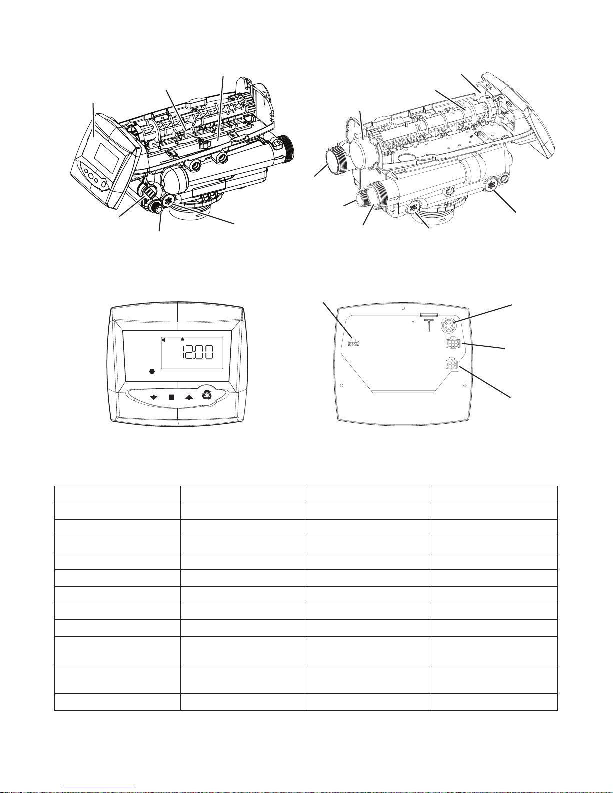
Valve Layout
Valve Discs
Analyzer Control
Rell Controller
Regenerant Tube Connection
Analyzer Control Layout
SU MO TU WE TH FR SA DAYS
Time/Day
Regeneration Time/Day
Salt Amount
Capacity
Check Salt
One Piece Valve Disc Spring
Injector and Cap
Status Light Connection
PM
Outlet
Drain
Motor
Inlet
Optical Sensor
Camshaft
Injector Screen Filter
Backwash Drain Control
AC Adapter Connection
(12 Volt Input)
Motor & Optical
Sensor Connection
Analyzer Probe
Connection
Front Back
System Specications 716
Model Number 268-716-100-1044 268-716-150-1248 268-716-200-1248
Recharge Style Analyzer Analyzer Analyzer
Media Tank Size 10" x 44" (25 x 112 cm) 12" x 48" (30.5 x 122 cm) 12" x 48" (30.5 x 122 cm)
Resin Volume
Recharge (Salt) Tank Size 19" x 36" (48.3 x 91.5 cm) 19" x 36" (48.3 x 91.5 cm) 19" x 36" (48.3 x 91.5 cm)
Salt Storage 240 lbs (109 kg) 240 lbs (109 kg) 240 lbs (109 kg)
Drain Water Rate 2.7 gpm (10.2 L/m) 3.9 gpm (14.7 L/m) 3.9 gpm (14.7 L/m)
Service Connection Size 1" NPT 1" NPT 1" NPT
Drain Connection Size 3/4" NPT 3/4" NPT 3/4" NPT
Recharge (Brine)
Connection Size
Installation Space
Requirements
Shipping Weight 140 lbs (63.5 kg) 165 lbs (74.8 kg) 200 lbs (90.7 kg)
1 ft3 (0.03 m3) 1.5 ft3 (0.04 m3) 2 ft3 (0.056 m3)
3/8" NPT 3/8" NPT 3/8" NPT
21" x 42" x 72"
(53.3 x 106.6 x 182.8 cm)
21" x 42" x 72"
(53.3 x 106.6 x 182.8 cm)
21" x 42" x 72"
(53.3 x 106.6 x 182.8 cm)
5

Location Selection
Location of a water conditioning system is important. The
following conditions are required:
• Level platform or oor.
Note: The Pro Elite System can be provided with optional
leveling feet that may be used on the two tanks. Order
part number 4000409.
• Room to access equipment for maintenance and
adding regenerant (salt) to tank.
• Ambient temperatures over 34°F (1°C and below
120°F (49°C).
• Water pressure below 125 psi (8.62 bar) and above
20 psi (1.38 bar).
• In Canada the water pressure must be below 100 psi
(6.89 bar).
• Constant electrical supply to operate the control.
• Total minimum pipe run to water heater of ten feet
(three meters) to prevent backup of hot water into
system.
• Local drain for discharge as close as possible.
• Water line connections with shuto or bypass
valves.
• Must meet any local and state codes for site of
installation.
• Valve is designed for minor plumbing misalignments.
Do not support weight of system on the plumbing.
• Be sure all soldered pipes are fully cooled before
attaching plastic valve to the plumbing.
WARNING: Dry location use only, unless
used with a Listed Class 2 Power Supply
suitable for outdoor use.
Outdoor Locations
It is recommended that the Pro Elite conditioner be
installed in a protected environment.
When installing the water conditioning system outdoors,
several items must be considered:
• Moisture – The valve and control are rated for
NEMA 3 locations. Falling water should not aect
performance. The system is not designed to
withstand extreme humidity or water spray from
below. Examples are: constant heavy mist, near
corrosive environment, or upwards spray from
sprinkler. Ensure that the Analyzer probe access
panel is installed on the unit.
• Direct Sunlight – The materials used will fade or
discolor over time in direct sunlight. The integrity
of the materials will not degrade to cause system
failures.
• Temperature – Extreme hot or cold temperatures
will cause damage to the valve or control. Freezing
temperatures will freeze the water in the valve. This
will cause physical damage to the internal parts as
well as the plumbing and conditioning resin. High
temperatures will aect the control. The display may
become unreadable but the control should continue
to function. When the temperature returns to
normal operating limits, the display will re-appear. A
protective cover should assist with high temperature
applications.
• Insects – The control and valve have been designed
to keep all but the smallest insects out of the critical
areas. Any holes in the top plate can be covered with
duct tape. The top cover should be installed securely
in place.
6
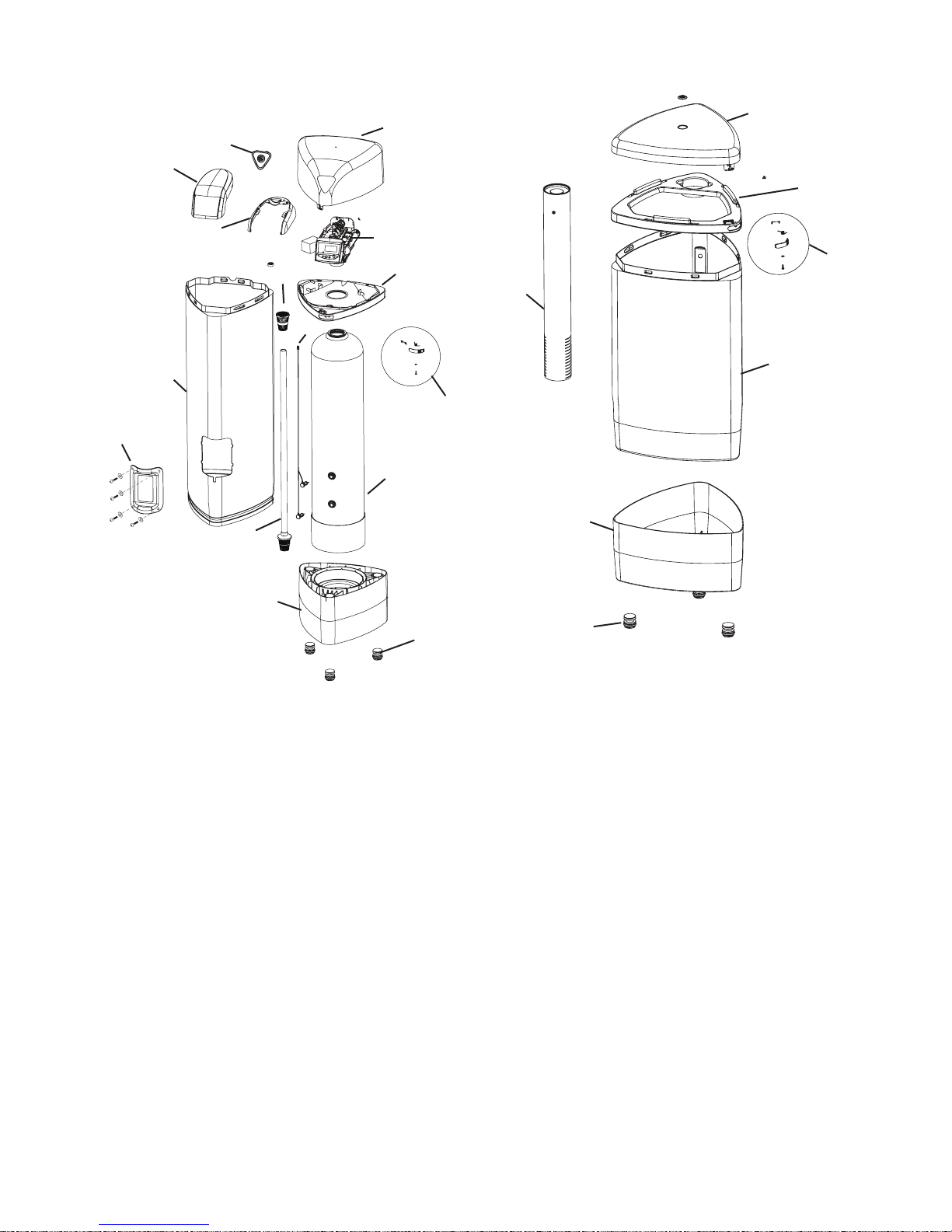
System Features
Brine Tank
Resin Tank
7
14
1
2
15
13
8
3
12
1
2
5
7
11
5
3
10
6
4
1 Cover
2 Cap, Cover
3 Jacket,Resin Tank
4 Base
5 268 Logix PE Valve
w/716 Control
6 Resin Tank
7 Door, Access,
Sensor
Sensors Wired
8
Probes
4
9 Foot, Leveling
10 Latch Mechanism
11 Tank Collar
12 Riser Tube
13 Upper Basket
14 Cover
15 Shield
9
1 Cover 5 Brine Tube
2 Collar, Tank 6 Foot, Leveling
3 Tank, Brine 7 Latch Mechanism
4 Base, Tank
6
Assembly
7
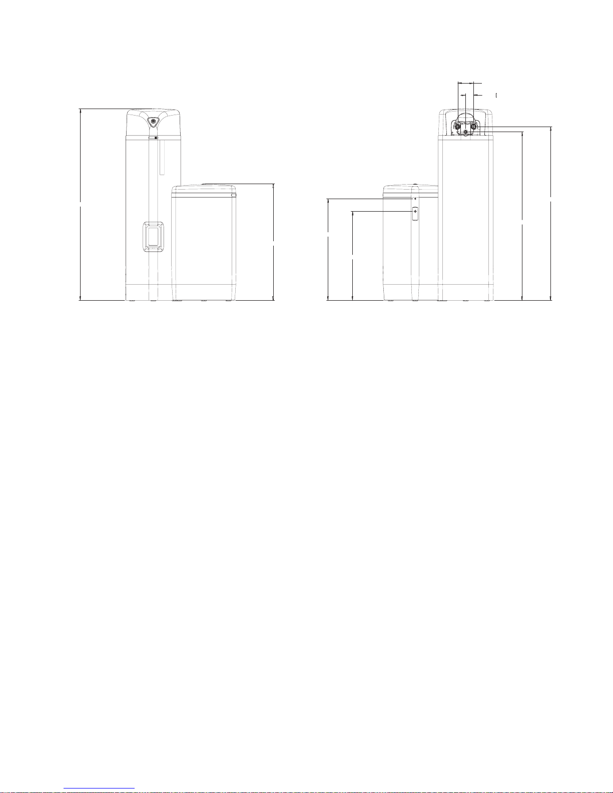
Equipment Installation
60.7 (1541.6)
55 (1398.1)
5.0 (127)
Dimensions
2.5 (63.5)
53.4 (1356.6)
32.2 (817.5)
36.9 (938.1)
28.2 (715.9)
8
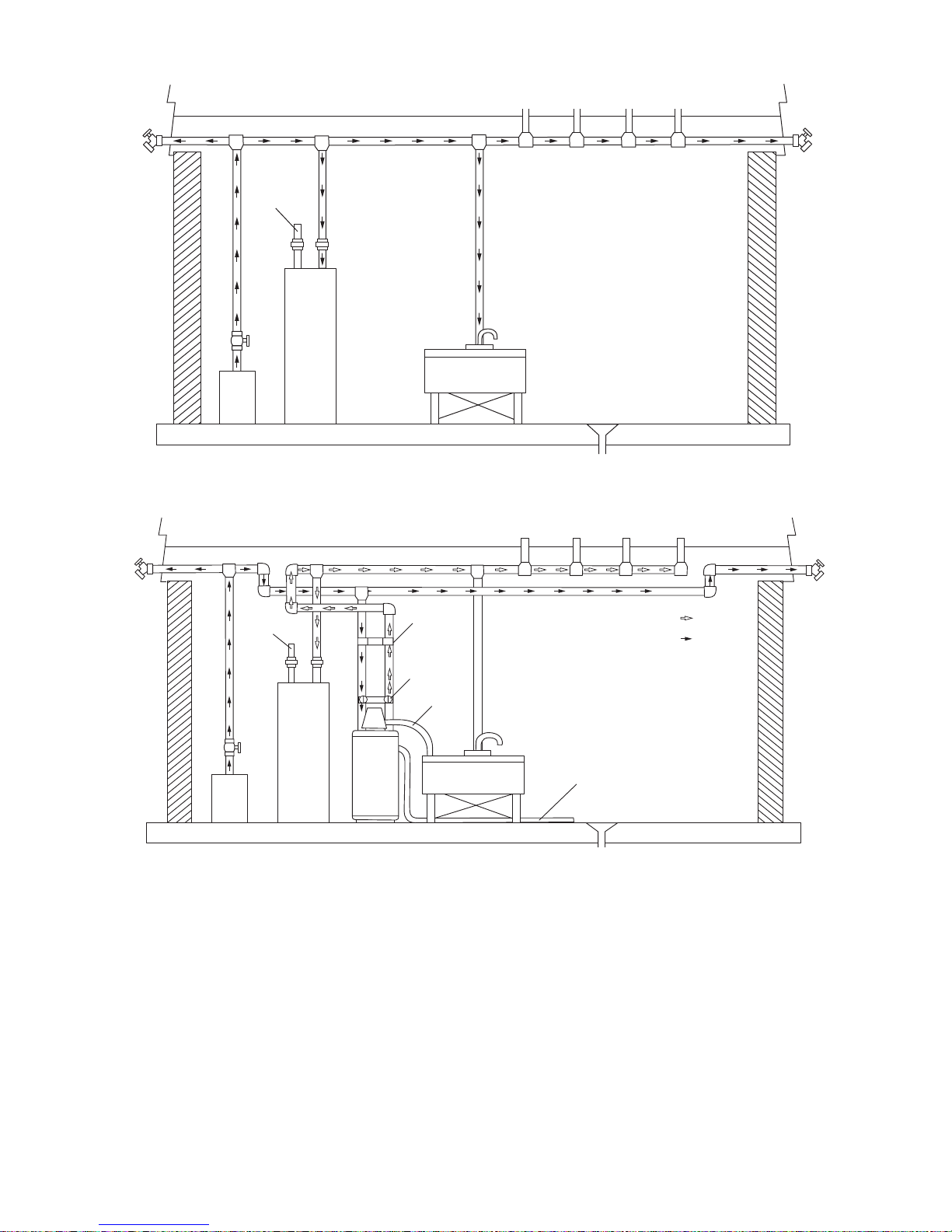
Typical System Layout
Bath TubLavatoryToilet Kitchen
Outside
Faucet
Outside
Faucet
Hot Water
Outlet
Water
Heater
Pump
Laundry Tubs
or
Meter
Floor Drain
Figure 1 Standard Basement Before Installation. Cold water lines shown.
Bath TubLavatoryToilet Kitchen
Hot Water
Outlet
Grounding
Strap
Outside
Faucet
Outside
Faucet
Soft Water
Hard Water
Pump
or
Meter
Water
Heater
Bypass
Drain Line
Softener
Laundry Tubs
Brine Tank Overow Drain
Figure 2 Softened Water Flow Diagram.
Floor Drain
9
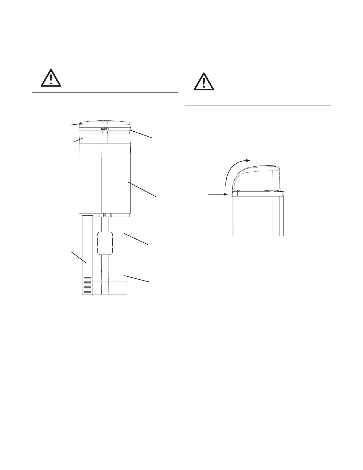
Inspection
The Pro Elite system is shipped with several parts
unassembled. When parts are removed from the packing,
they should be inspected for damage. If any parts are
damaged or missing, contact your supplier.
WARNING: When handling the media
tank do not turn it upside down or drop
When the carton is rst opened, the softener will be
standing upright. The salt tank will be turned over and
covering the softener (Figure 3).
Salt Tank Cover
Salt Tank Base
on its side.
Salt Tank Collar
Salt Tank
(Upside Down)
To Assemble the Media Tank:
1. If the oor under the media tank is uneven, the
leveling feet may be installed. Slowly lay the tank on its
side. Press or tap the feet into the pockets.
WARNING: The media tank contains
loose particles that will shift. If the tank is
turned upside down or laid back quickly,
the particles may enter the valve. If
this happens, the valve may need to be
disassembled and cleaned.
2. Stand the tank up and in position. Level as needed.
3. Remove cover by pressing in on the latch and lifting
cover (Figure 4). When the cover is removed, the valve
is visible. Remove the power adapter. They should
be secured to the tank collar near the inlet/outlet
connections.
Lift
Press in
Brine Tube
Assembly
Media Tank
(Softener)
Media Tank Base
Figure 3
To assemble the system, remove the salt tank
components (cover, collar, base and brine tube assembly)
from the shipping container. The media tank can now be
removed. Locate the miscellaneous parts bag.
To assemble the Salt Tank:
1. If the oor under the salt tank is uneven, the leveling
feet may be installed. Lay the empty salt tank on its
side. Press or tap the feet into the pockets.
2. Stand the salt tank up and in position. Level as needed.
The tank has two ports that will be connected. One to
a drain and one to the valve.
3. Place the brine tube in position inside the pocket at
the bottom of the tank. Install the overow tting.
4. Place the tank collar over the top of the brine tube.
Position the collar and push it down into the tank. Lay
the cover aside for now.
Figure 4
Tank and Probe Assembly
The probes are preinstalled to the media tank. The probes
are located behind an access panel on the jacket of the
media tank. To remove the access panel, remove the four
screws and washers.
Use only 100% silicone lubricant on the probe O-rings
(Figure 5). Do not allow the lubricant to come into contact
with the probe pins. Install the probe assemblies into the
tank and secure with the locking clasp (Figure 6).
Important: The pins on the probes will only t into the
bulkhead ttings one way. The pins must go into the
matching holes at the bottom of the tting. The probe with
the shortest length of wire must be on top.
Install the protective shield (Figure 6 ).
Note: Do not attempt to tighten or loosen the Bulkhead
ttings, as they are secured with a locking adhesive.
10
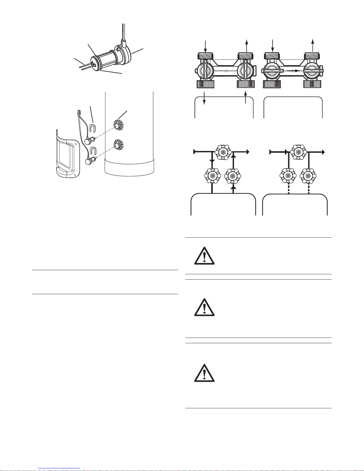
Normal Operation
In Bypass
O-ring
Probe
Probe Pins
Lubricate
Figure 5
Locking Clasp
Bulkhead
Fitting
Figure 6
Water Line and Bypass Connections
A bypass valve system should be installed on all water
conditioning systems. A model 1265 bypass is included
with this system. The bypass valve isolates the conditioner
from the water system and provides unconditioned water
to service during routine maintenance and servicing
procedures. See Figure 7 Model 1265 Bypass (Included)
and Figure 8 Typical Three Valve Bypass Conguration
(Not provided by manufacturer).
Note: Before turning on the water to the valve, rotate
the two handles on the bypass valve 2-3 times. This will
help seat the O-rings and prevent leaking.
In
B
Y
P
A
S
S
Out
B
Y
P
A
S
S
In
A
P
S
Y
S
B
Water Conditioner Water Conditioner
Figure 7 Model 1265 Bypass (Included)
Normal Operation
Water Conditioner Water Conditioner
In Bypass
Figure 8 Typical Three Valve Bypass Conguration
(Not provided by manufacturer)
WARNING: Do not use tools to tighten
plastic ttings. Over time, stress may
break the connections. Hand tighten the
nuts.
WARNING: Do not use petroleum grease
on gaskets when connecting bypass
plumbing. Use only 100% silicone grease
products when installing any Pro Elite
brand valve. Non-silicone grease may
cause plastic components to fail over
time.
Out
A
S
S
P
Y
B
11
WARNING: The inlet water must be
connected to the inlet port of the valve.
When replacing non-Pro Elite valves,
it is possible that the inlet and outlet
plumbing is installed in a reversed
position. Ensure that the plumbing is
not installed in the opposite order. Tank
media may be pushed into the valve.
 Loading...