

Page 1

PRODIGY
Part Number: LUN7396
Revision: C
Service Manual
Page 2

This page left blank intentionally.
ii Prodigy Service Manual
Page 3

This document contains confidential or proprietary information of GE-Lunar Corp. neither the
document nor the information is to be reproduced, distributed, used or disclosed, either in whole or
in part, except as specifically authorized by GE-Lunar Corp.
GE-LUNAR Corporation makes no warranty of any kind with regard to this material, and shall not be
held liable for errors contained herein or for incidental or consequential damages in connection
with the furnishings or use of this manual.
Read through this manual thoroughly before attempting to service any components. Unauthorized
service may void system warranties or service contracts. Consult the GE-LUNAR Customer
Support Department prior to attempting any servicing:
608-828--2663
608-826-7107 (Fax)
is a registered trademark of General Electric Company.
g
PRODIGY® is a trademark of GE-LUNAR Corporation.
Windows NT® is a trademark of Microsoft Corporation
Copyright© 2000 by GE-LUNAR Corporation.
Madison, Wisconsin. All rights reserved.
Prodigy Service Manual iii
Page 4

This page left blank intentionally.
iv Prodigy Service Manual
Page 5

READ THIS FIRST
Using This Manual:
A person who will be performing service work on the PRODIGY should use this manual in the
following manner:
Read the Safety and Overview Chapters to familiarize yourself with the scanner as a whole and
with the general function of the circuit boards.
Chapter 3 should be understood completely as it explains the Diagnostics Software (built in –
requires a password for access).
The Chapter 4 and Chapter 5 contain common procedures and troubleshooting information and
can be read as needed, but are good sources of information.
When a problem arises, Chapter 4 should be referenced. Check the table of contents for Chapter 4
to see if the problem being experienced is described. If so, refer to the appropriate page. If not, try
to generalize the problem (e.g. the Detector is repeatedly running into the front of the scanner and
reversing and then running back into the front of the scanner. This is a mechanical problem in
general, specifically with Transverse Mechanics, check that subsection of Chapter 4 for the
subsystem experiencing the fault.
This manual commonly references other Sections and pages of the manual as needed, so often
procedures in the Chapter 5 Appendix are referred to as ways to solve problems described in
Chapter 4.
Information Requested By GE-LUNAR:
When requesting assistance from GE-LUNAR, please provide the following information:
System Number (DF+xxxxx)
Institution or Doctor's name
Location
Complete list of symptoms
Names and part numbers of parts needed for service
Prodigy Service Manual v
Page 6

In addition to the information above, an Error Log printout and QA’s and QA history or other failing
diagnostic test printout (Alignment Test etc.) will also help to improve the accuracy of our
diagnosis:
For problems with specific patient scans, it is recommended that you copy the scan files to
diskette, and send it, with a description of the problem, to the Applications Department at GE LUNAR.
vi Prodigy Service Manual
Page 7

1 1112
Safety
Chapter 1:Safety
This chapter highlights safety devices and features a Service
Engineer should know before servicing a PRODIGY system.
Chapter Contents:
1.0 General Safety . . . . . . . . . . . . . . . . . . . . . . . . . . . . . . . . . . . . . . . . . 1-15
1.1 Symbols and labels found on the PRODIGY . . . . . . . . . . . . . . . . . . 1-15
1.1.1 External Symbols. . . . . . . . . . . . . . . . . . . . . . . . . . . . . . . . . . . 1-15
1.1.2 Internal Symbols . . . . . . . . . . . . . . . . . . . . . . . . . . . . . . . . . . . 1-16
1.1.3 Labels . . . . . . . . . . . . . . . . . . . . . . . . . . . . . . . . . . . . . . . . . . . 1-16
1.2 Emergency Stop Button . . . . . . . . . . . . . . . . . . . . . . . . . . . . . . . . . . 1-19
1.3 Laser Exposure . . . . . . . . . . . . . . . . . . . . . . . . . . . . . . . . . . . . . . . . 1-20
1.4 Shutter Indicator . . . . . . . . . . . . . . . . . . . . . . . . . . . . . . . . . . . . . . . . 1-21
1.5 Cautions, Warnings, and Notes . . . . . . . . . . . . . . . . . . . . . . . . . . . . 1-21
1.5.1 Caution Statements. . . . . . . . . . . . . . . . . . . . . . . . . . . . . . . . . 1-21
1.5.2 Warning Statements . . . . . . . . . . . . . . . . . . . . . . . . . . . . . . . . 1-22
1.5.3 Note Statements . . . . . . . . . . . . . . . . . . . . . . . . . . . . . . . . . . . 1-22
1.6 Safety Concerns. . . . . . . . . . . . . . . . . . . . . . . . . . . . . . . . . . . . . . . . 1-22
1.6.1 Pinch points. . . . . . . . . . . . . . . . . . . . . . . . . . . . . . . . . . . . . . . 1-22
1.6.2 Laser safety. . . . . . . . . . . . . . . . . . . . . . . . . . . . . . . . . . . . . . . 1-23
1.6.3 Radiation safety. . . . . . . . . . . . . . . . . . . . . . . . . . . . . . . . . . . . 1-24
1.6.4 Scatter Radiation. . . . . . . . . . . . . . . . . . . . . . . . . . . . . . . . . . . 1-24
1.7 Controlling Computer and Accessories . . . . . . . . . . . . . . . . . . . . . . 1-26
1.7.1 Electrical Safety. . . . . . . . . . . . . . . . . . . . . . . . . . . . . . . . . . . . 1-26
1.7.3 Peripheral Configurations . . . . . . . . . . . . . . . . . . . . . . . . . . . . 1-26
1.7.4 Standard r oom configuration (system no. DF+12000 and greater)126
1.7.5 Small room configuration (system no. DF+12000 and higher) 1-27
1.7.6 Scanner power output configuration (system no. DF+11999 and
lower) . . . . . . . . . . . . . . . . . . . . . . . . . . . . . . . . . . . . . . . 1-27
1.7.7 W all outlet configurat ion (system no. DF+11999 and lower) . . 1-27
Figure 1-1. The PRODIGY Display Panel . . . . . . . . . . . . . . . . . . . . . . . 1-19
Figure 1-2. Laser Warning Label (U.S. systems only) . . . . . . . . . . . . . . 1-20
Figure 1-4. Laser Warning Label (International systems only). . . . . . . .1-20
Figure 1-5. Source (x-rays) off - Shutter closed (green). . . . . . . . . . . . . 1-21
PRODIGY Service Manual (Rev C - 2000) Safety113
Page 8

Figure 1-6. Source (x-rays) on - Shutter open (yellow). . . . . . . . . . . . . . 1-21
Figure 1-7. Potential Pinch Points on the PRODIGY . . . . . . . . . . . . . . .1-23
Figure 1-8. PRODIGY Iso-Dose Diagram. . . . . . . . . . . . . . . . . . . . . . . .1-25
This document contains confidential or proprietary information of GE-Lunar Corp. Neither the document nor the information therein is
to be reproduced, distributed, used or disclosed, either in whole or in part, except as specifically authorized by GE-Lunar Corp.
1-14 Safety PRODIGY Service Manual (Rev C - 2000)
Page 9

1.0 General Safety
• DO NOT attempt to service the PRODIGY without first reading this
manual.
• DO NOT attempt any repairs without prior instructions from authorized
LUNAR personnel.
• In order to maint ain electrical safety and electromagnetic compatibility,
the Lunar PRODIGY is only to be connected to a computer, printer, and
peripherals that are certified to be compliant with IEC 950/EN 60950
Safety of inf ormation technol ogy equip ment, i ncludin g electri cal busi ness
equipment and IEC 601-1-2 Medical electrical equipment, Part 1:
General requiremen ts for safet y, 2. Collateral Standard : El ec trom agn et ic
compatibility - Requirements and tests. Emergency Stop Button
1.1 Symbols and labels fou nd on the PRODIGY
1.1.1 External Symbols
• The following symbols are found on the PRODIGY, in the Operators
manual, and in the Service Manual.
Attention: contains important safety information such as the
location of a pinch point.
Emergency Stop Button: shows the location of the
emergency stop butt on.
Power On: shows the location of th e Pow er O n in di c at or an d the
switch position for Power On.
Power Off: shows the switch position for Power Off.
Laser On: shows t he locati on of the Las er On indi cator. It is found
only on systems delivered internationall y.
This document contains confidential or proprietary information of GE-Lunar Corp. Neither the document nor the information therein is
to be reproduced, distributed, used or disclosed, either in whole or in part, except as specifically authorized by GE-Lunar Corp.
PRODIGY Service Manual (Rev C - 2000) Safety1-15
Page 10
Shutter Open: shows the location of the Shutter Open indicator.
X-ray On: shows the locati o n of th e X-Ra y On ind ic a to r.
Type B Equipment: shows that the scanner has Type B
protection against electrical shock.
1.1.2 Intern al Symbols
• The followin g symbo ls are found insi de th e PRODIGY, and in the Ser vice
Manual.
Protective Earth: shows the locati on of a Protective Earth
Terminal.
Functional Earth: shows the location of a Functional Earth
Terminal.
1.1.3 Labels
• The following labels are found on the PRODIGY Scanner.
Laser Caution Label: Shows that the scanner u ses
a Class II laser. This label is not found on systems
shipped to Canada.
Laser Caution Label: Canada only
This document contains confidential or proprietary information of GE-Lunar Corp. Neither the document nor the information therein is
to be reproduced, distributed, used or disclosed, either in whole or in part, except as specifically authorized by GE-Lunar Corp.
1-16 Safety PRODIGY Service Manual (Rev C - 2000)
Page 11
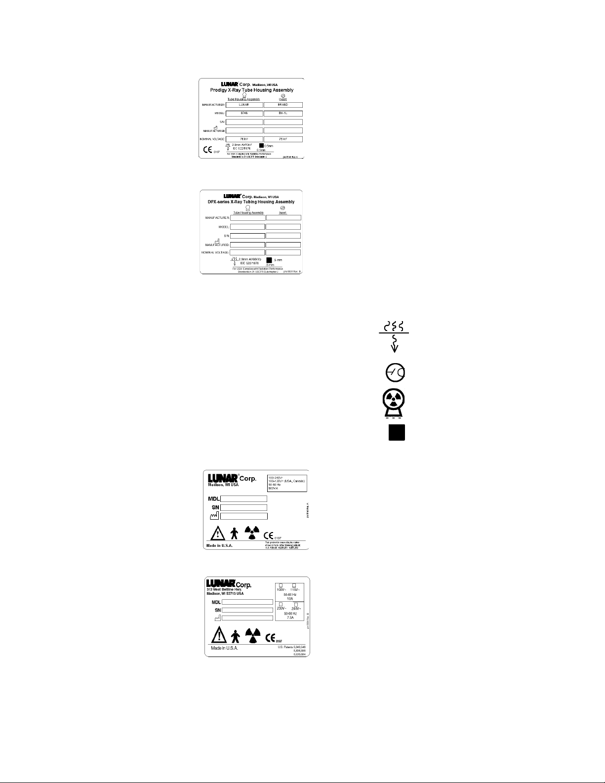
Tube Head Assembly La bel (system number
DF+12000 and gr eater ): This label gives tube head
assembly and x-ray source characteristics
information. I t is lo cat ed on the t ub e hea d ass embly
and the foot panel of the scanner.
Tube Head Assembly La bel (system number
DF+11999 and lower): This label gives tube he a d
assembly and x-ray source characteristics
information. I t is lo cat ed on the t ub e hea d ass embly
and the foot panel of the scanner.
A definition of each symbol on this label follows:
Inherent Filtration
Tube Insert
X-ray Source
Focal Point
System Label (system number DF+12000 and
greater): This label gives system input power
requirements and compliance information. It is
located on the foot panel of scanners. The CE
mark shows compliance with UL/CSA and the
Medical Device Directive 93/42/EEC.
System Label (system number DF+11999 and
lower): This label gives system input power
requirements and compliance information. It is
located on the foot panel of scanners. The CE
mark shows compliance with UL/CSA and the
Medical Device Directive 93/42/EEC.
This document contains confidential or proprietary information of GE-Lunar Corp. Neither the document nor the information therein is
to be reproduced, distributed, used or disclosed, either in whole or in part, except as specifically authorized by GE-Lunar Corp.
PRODIGY Service Manual (Rev C - 2000) Safety1-17
Page 12
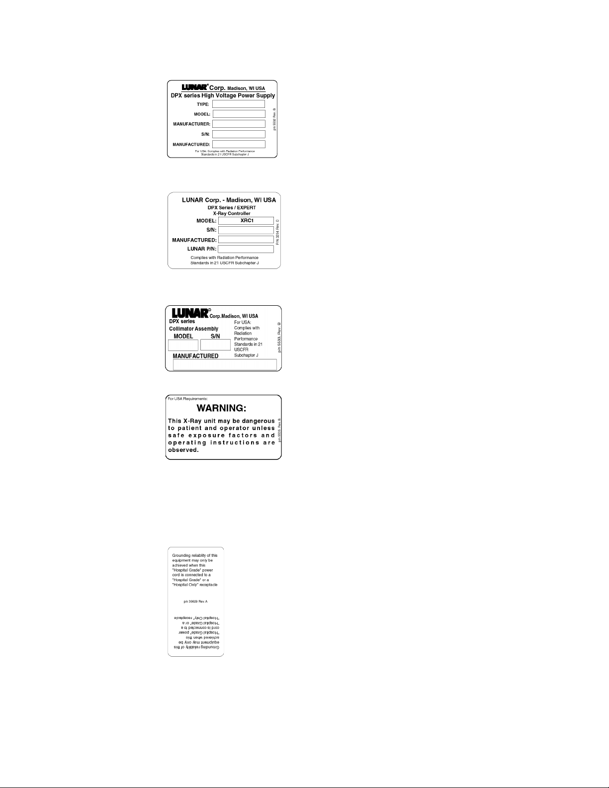
High Voltage Power Supply: This label gives
high voltage power supply (x-ray generator)
information. It is located on the positive and
negative power supplies, and foot panel of t he
scanner.
X-ray Controller: This label shows x-ray
controller compliance. It is located on the foot
panel of the scanner.
Collimator Assembly: This label gives
collimator assembly information. It is located on
the collimator and foot panel of the scanner.
Warning Label and Radiation Symbol: The
Warning label shows that the system uses
ionizing radiation. It is found only on systems
delivered in the United States. Always obey
instructions for safe operation.
Radiation Label: This label shows that the system uses
ionizing radiat ion.
Grounding Reliability Label: This label states that
grounding reliability can only be maintained when using a
“Hospital Gra de” or “Hospi tal Only” r eceptacle. I t is only f ound
on systems delivered in the United States.
This document contains confidential or proprietary information of GE-Lunar Corp. Neither the document nor the information therein is
to be reproduced, distributed, used or disclosed, either in whole or in part, except as specifically authorized by GE-Lunar Corp.
1-18 Safety PRODIGY Service Manual (Rev C - 2000)
Page 13

1.2 Emergency Stop Button
• The Emergency S top Bu tton is a round red butt on locat ed on t he scanne r
display panel (see Figure 1-1). When pressed, power is removed from
the X-ray tube head, the laser, and the shutter is closed. Power is also
removed from the scan ar m motors, al lowing the operator /patie nt to push
the scan arm out of the way.
Figure 1-1. The PRO DIGY Display Panel
This document contains confidential or proprietary information of GE-Lunar Corp. Neither the document nor the information therein is
to be reproduced, distributed, used or disclosed, either in whole or in part, except as specifically authorized by GE-Lunar Corp.
PRODIGY Service Manual (Rev C - 2000) Safety1-19
Page 14

1.3 Laser Exposure
• The PRODIGY is equipped with a Class II Laser device. This laser is
used for patient posi tioning. A Class II rati ng indicates a low power vis ible
laser that is not normally hazardous to eyesight but has the potential t o
be hazardous if viewed directly for an extended period of time. Because
of this potential hazard, DO NOT stare directly into the beam while the
laser is in operation, and DO NOT allow the beam to shine directly into
the patients' e y es. No specific eye protection is required with a Class II
laser.
• A amber laser-on indicator, located on the front of th e scan arm, is lit
when the laser is on. The program activates the laser during positioning
for an image acquisition. The program then turns off the laser when you
begin the scan. The emergency stop button will turn off the laser.
• There is a caution label (Figure 1.2) on the sc an arm near the Display
Panel.
Figure 1-2. Laser Warning Label (U.S. systems only)
Figure 1-3. Laser Warning Label (Canadian Systems only)
Figure 1-4. Laser Warning Label (International systems only)
Note: DO NOT STARE INTO THE BEAM while the laser is
operating.
This document contains confidential or proprietary information of GE-Lunar Corp. Neither the document nor the information therein is
to be reproduced, distributed, used or disclosed, either in whole or in part, except as specifically authorized by GE-Lunar Corp.
1-20 Safety PRODIGY Service Manual (Rev C - 2000)
Page 15
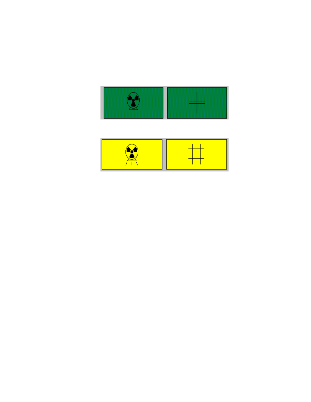
1.4 Shutter Indicator
• This symbol is used to indicate an open-shutter condition in acco rdance
with the safety standards established by the International
Electrotechnical Commission (IEC).
Figure 1-5. Source (x-rays) off - Shutter closed (green)
Figure 1-6. Source (x-rays) on - Shutter open (yellow)
• This symbol appears near the yellow X-ray s hutter-open indicator light.
The X-ray shutter-open indicator light is located on the Display Panel on
the scan arm near the fr ont.
Note: When the x-ray on / shutter open symbol appears in literature
associated with the PRODIGY scanner, it will be used to
indicate that the pr ocedur e being descr ibed resul ts in an openshutter condition. During these times personnel should
exercise cautio n to avoid excessive exposure to the X-rays.
1.5 Cautions, Warnings, and Notes
• This manual contains warning and caution statements wherever
appropriate for your safety. The warnings and cautions used throughout
the manual are based on the safety standards established by the
Internationa l Electrotechnical Commission (IEC). In addition, the manual
uses notes to attract the reader's attention to important information.
1.5.1 Caution Statements
A caution statement reflects a condition
that, if not avoided, could cause
equipment or property damage.
This document contains confidential or proprietary information of GE-Lunar Corp. Neither the document nor the information therein is
to be reproduced, distributed, used or disclosed, either in whole or in part, except as specifically authorized by GE-Lunar Corp.
PRODIGY Service Manual (Rev C - 2000) Safety1-21
Page 16

1.5.2 Warning Statements
1.5.3 Note Statements
Note: This symbol turns the reader's attent ion to important
information whi ch may otherwise be overlooked.
1.6 Safety Concerns
1.6.1 Pinch points
The Warning label below identifies the location of possible pinch points
A warning statement reflects a potentially
hazardous condition that, if not avoided, could
result in serious injury.
Because the PRODIGY Densitometer
contains moving parts, there are places
on the scanner where there is a danger
of pinching. Operat ors should be aware
of these pinch points to avoid injury to
the patient or themselves. When the scanner arm is in
motion, make sure possible pinch point locat ions are
clear at all ti mes. L abels appli ed at the LU NAR fac tory
indicate the location of the pinch points. The pinch
points and the ir labels are shown in the fi gure 1-7.
This document contains confidential or proprietary information of GE-Lunar Corp. Neither the document nor the information therein is
to be reproduced, distributed, used or disclosed, either in whole or in part, except as specifically authorized by GE-Lunar Corp.
1-22 Safety PRODIGY Service Manual (Rev C - 2000)
Page 17

Figure 1-7. Potential Pinch Points o n the PRODIGY
1.6.2 Laser safety
Do not touch the AC Surge Suppressor
(located on the AC terminal block) it
may be hot.
Do not electrically connect the isolation
transformer bolt head to ground, doing
this will short out the transformer
Scan table isolated outlet strip must be
appropriately connected.
DO NOT STARE INTO THE LASER BEAM
during patient positioning and Quality
Assurance procedures.
The label that foll ows i s located on the sc anner ar m and shows the loca tion of
the laser aperture.
This document contains confidential or proprietary information of GE-Lunar Corp. Neither the document nor the information therein is
to be reproduced, distributed, used or disclosed, either in whole or in part, except as specifically authorized by GE-Lunar Corp.
PRODIGY Service Manual (Rev C - 2000) Safety1-23
Page 18

1.6.3 Radiatio n safety
X-ray exposure: The system makes radiation when el ectric voltage is
supplied to, a nd cur rent f lows t hrough , the x-ray tube. D uring a measu remen t,
the shutter opens to let a beam of radiation pass through the scanner table
and patient. The radiation field at the table top is 19.2 mm x 3.3 mm. Lead
oxide shielding surrounds the x-ray tube in sert inside the tube housing
assembly and reduces radiation levels around the scanner table.
Skin entrance dose: Table 1 of the PRODIGY Operators Safety and
Specifications manual shows irradiation times and skin entrance doses.
1.6.4 Scatter Radiation
• There is some scatter radiation from the PRODIGY when it is running.
Figure 1-8 shows the radiation dosages while the scanner is running at
3.00 mA at certain distances.
• These dosages ar e relatively insignificant as the allowed yearly dosage
for a person working with radiation emitting equipment is 5000 mRem.
Radiation however should be avoided when possible.
This document contains confidential or proprietary information of GE-Lunar Corp. Neither the document nor the information therein is
to be reproduced, distributed, used or disclosed, either in whole or in part, except as specifically authorized by GE-Lunar Corp.
1-24 Safety PRODIGY Service Manual (Rev C - 2000)
Page 19
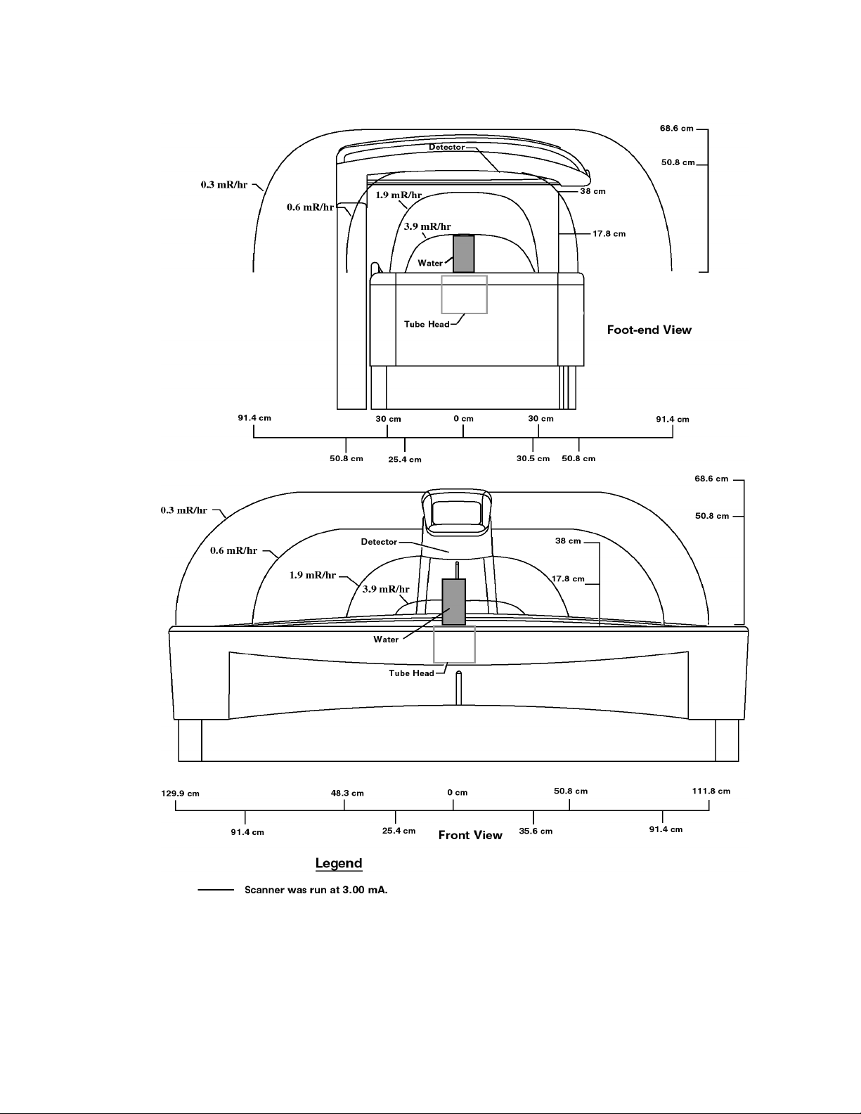
Figure 1-8. PRODIGY Iso-Dose Diagram
This document contains confidential or proprietary information of GE-Lunar Corp. Neither the document nor the information therein is
to be reproduced, distributed, used or disclosed, either in whole or in part, except as specifically authorized by GE-Lunar Corp.
PRODIGY Service Manual (Rev C - 2000) Safety1-25
Page 20

1.7 Controlling Computer and Accessories
1.7.1 Electrical Safety IEC and UL/CSA certification
IEC: To maintain elect ric al sa fe ty, all computer equi p me nt and accessorie s
connected to the scanner must meet all IEC require m ents for safety, such as
IEC 950, "Safety of information technology equipment, including electrical
business equipment," and IEC 801-5, "EMC Surge Immunity Requirements."
The computer and all accessories must have the CE label.
UL/CSA: To maintain elec trical safety, all computer equipment and
accessories conn ected to th e sc ann er mu st h ave safet y a gen cy appr o val s for
UL/CSA.
1.7.2 Electromagnetic interference
Although the sca nner meets safety standards regarding electromagnet ic
interference (EN60601-1-2), you may still e x perience a loss of performance
under extreme el ectromagnetic conditions. Maximize the distance betwee n
the scanner and ot her equipment, and use a dedicated power line, to avoid
interference to and from the scanner.
1.7.3 Peripheral Configurations
The correct connection of the computer and all
peripherals is necessary to maintain electrical
safety. The signal cable of the scanner is
intended only for connection to an approved
computer. Call LUNAR Support or your LUNAR
distributor before adding periph erals .
Note: The scanner's output power strip can be used to supply the
Host PC with isolated power. If it is to be used the foll owing
conditions must be met. If the conditions cannot be met, the
scanner's output power strip cannot be used.
Note: See also Peripheral Block Diagrams - Section 2.2.3
1.7.4 Standard room configuration (system no. DF+12000 and greater)
The computer, peripherals, and all other equipment must be located more
than 1.83 m from the scanner. Use an outlet strip to power the computer and
all peripherals. The outlet strip must be mounted off the floor so that it does
not touch other equipment. If your outlet strip was provided by LUNAR, it has
a maximum output of 15A, 120VAC. Only system-related equipment should
be powered by the outlet strip.
This document contains confidential or proprietary information of GE-Lunar Corp. Neither the document nor the information therein is
to be reproduced, distributed, used or disclosed, either in whole or in part, except as specifically authorized by GE-Lunar Corp.
1-26 Safety PRODIGY Service Manual (Rev C - 2000)
Page 21

A modem and/or netwo rk connecti on can be mad e at any t ime if you ar e using
the standard room configuration.
1.7.5 Small room configuration (system no. DF+12000 and higher)
You must power the computer, peripherals, and all othe r equipment with an
isolating trans for m er if th e roo m is to o sm a ll to ma in ta in at le as t 1. 83 m of
separation between the scanner and all other equipment.
The isolation transformer supplied by LUNAR has a maximum output of 400/
500VA. Only system-related equipment should be powered by the isolation
transformer. Failure to use an isolation transformer can cause leakag e
currents in excess of 100 microamperes.
A modem and/or net work connection can only be made in the small room
configuration if all exposed metal surfaces of the computer and peripherals
are out of the patien t en v iro n me n t.
1.7.6 Scanner power output configuration (system no. DF+11999 and lower)
LUNAR recommends that you use scanner power output to provide isolated
power to the computer and all peripherals. The power strip must be mounted
off the floor such that it does not touch other equipment. The computer and
ALL peripherals must be powered by the scanner. All other equipment must
not be powered by the scanner and must be located more than 1.83 m from
the scanner. Failure to u se sc ann er po we r out pu t ca n ca use le aka ge cu r rent s
in excess of 100 micr oamperes.
If a network and/or modem connection is needed, refer to the wall outlet
configuration.
1.7.7 Wall outlet configuration (system no. DF+11999 and lower)
As an option to scanner power output, a wall out let can be used to power the
computer and peripherals. Isolated power from the scanner must not be used
to power any equipment if a wall outlet is used. All exposed metal surfaces of
the computer, peripherals, and other equipment must be located more than
1.83 m from the scanner.
A network and/or mod em conne ction can be made to the comp uter if power is
supplied from a wall outlet as described abov e.
This document contains confidential or proprietary information of GE-Lunar Corp. Neither the document nor the information therein is
to be reproduced, distributed, used or disclosed, either in whole or in part, except as specifically authorized by GE-Lunar Corp.
PRODIGY Service Manual (Rev C - 2000) Safety1-27
Page 22

This page left blank intentionally.
This document contains confidential or proprietary information of GE-Lunar Corp. Neither the document nor the information therein is
to be reproduced, distributed, used or disclosed, either in whole or in part, except as specifically authorized by GE-Lunar Corp.
1-28 Safety PRODIGY Service Manual (Rev C - 2000)
Page 23

2 1112
System Overview
Chapter 1:System Overview
This chapter provides an overview of the PRODIGY system.
• In addition the chapter contains a brief discussion of majo r subsystems and illustrations of the PRODIGY power system.
• This Chapter contains the PRODIGY Block Diagrams
2.0 PRODIGY System . . . . . . . . . . . . . . . . . . . . . . . . . . . . . . . . . . . . . . 1-33
2.0.1 PRODIGY Electronics . . . . . . . . . . . . . . . . . . . . . . . . . . . . 1-33
2.1 Electronics . . . . . . . . . . . . . . . . . . . . . . . . . . . . . . . . . . . . . . . . . . . . 1-35
2.1.1 Cautions . . . . . . . . . . . . . . . . . . . . . . . . . . . . . . . . . . . . . . 1-35
2.1.2 Electronics Pan . . . . . . . . . . . . . . . . . . . . . . . . . . . . . . . . . 1-35
2.1.3 Scan Arm. . . . . . . . . . . . . . . . . . . . . . . . . . . . . . . . . . . . . . 1-36
2.1.4 Power specifications . . . . . . . . . . . . . . . . . . . . . . . . . . . . . 1-36
2.2 PRODIGY Block Diagrams. . . . . . . . . . . . . . . . . . . . . . . . . . . . . . . . 1-38
2.2.1 PRODIGY I (System numbers DF+11999 and lower) Power
Distribution Block Diagram (AC entrance) . . . . . . . . . . . . . . . . . 1-38
2.2.2 PRODIGY System Blo c k Diag ram PRODI GY I Sys tem Block
Diagram . . . . . . . . . . . . . . . . . . . . . . . . . . . . . . . . . . . . . . . . . . . 1-39
2.2.3 PRODIGY I Peripheral Configuration Block Diagrams . . . 1-40
2.2.4 PRODIGY II System / Power Block Diagram . . . . . . . . . . 1-41
2.3 PRODIGY Fusing . . . . . . . . . . . . . . . . . . . . . . . . . . . . . . . . . . . . . . . 1-42
2.4 PRODIGY I (system number s DF +11999 and lower) Single Board
Controller . . . . . . . . . . . . . . . . . . . . . . . . . . . . . . . . . . . . . . . . . . . . . . . . 1-43
2.4.1 SBC Functions . . . . . . . . . . . . . . . . . . . . . . . . . . . . . . . . . 1-43
2.4.2 SBC Reset. . . . . . . . . . . . . . . . . . . . . . . . . . . . . . . . . . . . . 1-43
2.4.3 SBC / Host PC Interface . . . . . . . . . . . . . . . . . . . . . . . . . . 1-44
2.5 PRODIGY II Combined Single Board Controller (cSBC) (systems
DF+12000 and greater) . . . . . . . . . . . . . . . . . . . . . . . . . . . . . . . . . . . . . 1-45
2.5.1 cSBC System Architecture . . . . . . . . . . . . . . . . . . . . . . . . . . . 1-45
2.5.2 cSBC Functions. . . . . . . . . . . . . . . . . . . . . . . . . . . . . . . . . . . . 1-46
2.5.3 TRANS / LONG MOTOR Control and Status . . . . . . . . . . . . . 1-50
2.5.4 AGS ROLL . . . . . . . . . . . . . . . . . . . . . . . . . . . . . . . . . . . . . . . 1-51
2.5.5 AGS DAC . . . . . . . . . . . . . . . . . . . . . . . . . . . . . . . . . . . . . . . . 1-51
2.5.6 SCANNER RESET . . . . . . . . . . . . . . . . . . . . . . . . . . . . . . . . . 1-52
2.5.7 GE-LUNAR Model 7861 X-ray Generator Errors. . . . . . . . . . . 1-53
2.5.8 DC FAIL. . . . . . . . . . . . . . . . . . . . . . . . . . . . . . . . . . . . . . . . . . 1-54
PRODIGY Service Manual (Rev C - 2000) System Overview229
Page 24

2.5.9 DCA / AGS / BIAS DAC's . . . . . . . . . . . . . . . . . . . . . . . . . . . . 1-54
2.5.10 KV/mA DAC. . . . . . . . . . . . . . . . . . . . . . . . . . . . . . . . . . . . . . 1-55
2.5.11 ARC/FIL DAC. . . . . . . . . . . . . . . . . . . . . . . . . . . . . . . . . . . . .1-55
2.5.12 PEAK DAC. . . . . . . . . . . . . . . . . . . . . . . . . . . . . . . . . . . . . . .1-55
2.5.13 MAX PLD Peripherals . . . . . . . . . . . . . . . . . . . . . . . . . . . . . .1-55
2.5.14 Interrupts . . . . . . . . . . . . . . . . . . . . . . . . . . . . . . . . . . . . . . . . 1-56
2.5.15 MASTER RESET. . . . . . . . . . . . . . . . . . . . . . . . . . . . . . . . . .1-56
2.5.16 SUICIDE RESET . . . . . . . . . . . . . . . . . . . . . . . . . . . . . . . . . .1-57
2.5.17 MISC OUT. . . . . . . . . . . . . . . . . . . . . . . . . . . . . . . . . . . . . . .1-57
2.5.18 MISC IN. . . . . . . . . . . . . . . . . . . . . . . . . . . . . . . . . . . . . . . . .1-57
2.5.19 Stepper Motor Control . . . . . . . . . . . . . . . . . . . . . . . . . . . . . .1-58
2.5.20 OMI Input. . . . . . . . . . . . . . . . . . . . . . . . . . . . . . . . . . . . . . . .1-59
2.5.21 Patient Positioners. . . . . . . . . . . . . . . . . . . . . . . . . . . . . . . . . 1-59
2.5.22 Limit Switches . . . . . . . . . . . . . . . . . . . . . . . . . . . . . . . . . . . .1-59
2.5.23 X-ray Source Control / Mechanical Interlocks . . . . . . . . . . . .1-59
2.5.24 Shutter / Collimator Drive. . . . . . . . . . . . . . . . . . . . . . . . . . . . 1-60
2.5.25 End of Exposure Alarm . . . . . . . . . . . . . . . . . . . . . . . . . . . . . 1-60
2.5.26 Panel LED's. . . . . . . . . . . . . . . . . . . . . . . . . . . . . . . . . . . . . .1-60
2.5.27 HVPS Control . . . . . . . . . . . . . . . . . . . . . . . . . . . . . . . . . . . . 1-60
2.5.28 ADC . . . . . . . . . . . . . . . . . . . . . . . . . . . . . . . . . . . . . . . . . . . .1-61
2.5.29 mA Low Range . . . . . . . . . . . . . . . . . . . . . . . . . . . . . . . . . . .1-61
2.5.30 Detector Interface . . . . . . . . . . . . . . . . . . . . . . . . . . . . . . . . .1-61
2.5.31 Communications Ports. . . . . . . . . . . . . . . . . . . . . . . . . . . . . .1-62
2.5.32 Debug RS-232 Port . . . . . . . . . . . . . . . . . . . . . . . . . . . . . . . . 1-62
2.5.33 Diagnostic LED's . . . . . . . . . . . . . . . . . . . . . . . . . . . . . . . . . .1-62
2.6 Power Distri bution (PRODIGY II Systems DF+1200 and greater) . .1-64
2.7 Tube Head and X-ray Insert . . . . . . . . . . . . . . . . . . . . . . . . . . . . . . .1-65
2.7.1 X-ray generation and Spectrum. . . . . . . . . . . . . . . . . . . . .1-65
2.8 X-ray Generator (High Voltage Power Supply(ies)) . . . . . . . . . . . . . 1-66
2.9 MAX Board (PRODIGY I systems DF+11999 and lower only) . . . . .1-67
2.9.1 MAX Board Function . . . . . . . . . . . . . . . . . . . . . . . . . . . . .1-67
2.9.2 Dedicated +28VDC power supply . . . . . . . . . . . . . . . . . . .1-67
2.10 XORB Board (PROD IGY I Systems DF+11999 and lower only). . .1-68
2.11 Detector Sub System . . . . . . . . . . . . . . . . . . . . . . . . . . . . . . . . . . .1-69
2.11.1 Detector Overview . . . . . . . . . . . . . . . . . . . . . . . . . . . . . .1-69
2.11.2 Detector Operation. . . . . . . . . . . . . . . . . . . . . . . . . . . . . . 1-69
2.11.3 Detector Daughter Board Overview. . . . . . . . . . . . . . . . .1-70
2.11.4 Detector Daughter Board Operation . . . . . . . . . . . . . . . .1-71
2.11.5 Detector Mother Board Overview. . . . . . . . . . . . . . . . . . .1-72
2.11.6 Detector Mother Board Operation . . . . . . . . . . . . . . . . . .1-72
2.12 FOINK (PRODIGY I Systems DF+11999 and lower only) . . . . . . . 1-74
2.12.1 FOINK Functions. . . . . . . . . . . . . . . . . . . . . . . . . . . . . . .1-74
2.12.2 Motion Control and Detection . . . . . . . . . . . . . . . . . . . . .1-74
2.13 Display Panel . . . . . . . . . . . . . . . . . . . . . . . . . . . . . . . . . . . . . . . . .1-75
2.14 Audible X-RAY OFF Signal. . . . . . . . . . . . . . . . . . . . . . . . . . . . . . . 1-77
This document contains confidential or proprietary information of GE-Lunar Corp. Neither the document nor the information therein is
to be reproduced, distributed, used or disclosed, either in whole or in part, except as specifically authorized by GE-Lunar Corp.
2-30 System Overview PRODIGY Service Manual (Rev C - 2000)
Page 25

2.15 X-Ray Collimator Subsystem . . . . . . . . . . . . . . . . . . . . . . . . . . . . .1-78
2.16 PRODIGY Specifications . . . . . . . . . . . . . . . . . . . . . . . . . . . . . . . . 1-79
2.16.1 Component specifications. . . . . . . . . . . . . . . . . . . . . . . . 1-79
2.16.2 Functional specifications. . . . . . . . . . . . . . . . . . . . . . . . . 1-79
2.16.3 Maximum scan area (long x transverse). . . . . . . . . . . . . 1-79
2.16.4 Programs. . . . . . . . . . . . . . . . . . . . . . . . . . . . . . . . . . . . . 1-80
2.16.5 Environmental specifications. . . . . . . . . . . . . . . . . . . . . . 1-80
2.16.6 Storage and transport environment. . . . . . . . . . . . . . . . . 1-81
2.16.7 X-ray gene rator (system no. DF+12000 and higher). . . . 1-81
2.16.8 X-ray gene rator (system no. DF+11999 and lower) . . . . 1-83
2.16.9 GE-LUNAR 8022 x-ray tube . . . . . . . . . . . . . . . . . . . . . . 1-85
2.16.10 GE-LUNAR 8743 x-ray tube head assembly (system no.
DF+12000 and higher) . . . . . . . . . . . . . . . . . . . . . . . . . . . . . . . . 1-86
2.16.11 LUNAR 6838 x-ray tube head assembly (system no.
DF+11999 and lower). . . . . . . . . . . . . . . . . . . . . . . . . . . . . . . . . 1-87
2.16.12 Laser specifications. . . . . . . . . . . . . . . . . . . . . . . . . . . . 1-88
2.16.13 Compatible components . . . . . . . . . . . . . . . . . . . . . . . . 1-89
2.16.14 FDA Certified Components (USA Only) . . . . . . . . . . . . 1-89
2.17 Secondary Calibration / Daily QA. . . . . . . . . . . . . . . . . . . . . . . . . . 1-91
2.17.1 Secondary Calibration overview . . . . . . . . . . . . . . . . . . . 1-91
2.17.2 Starti ng the Dail y Q A (se c on d ary calibration) . . . . . . . . . 1-91
Peak Test. . . . . . . . . . . . . . . . . . . . . . . . . . . . . . . . . . . . . . . . . . 1-92
2.17.3 Tests Performed in the Secondary Calibration . . . . . . . . 1-92
2.17.4 QA Database. . . . . . . . . . . . . . . . . . . . . . . . . . . . . . . . . . 1-94
Figure 2-9. PRODIGY System Exploded View of External Covers and
associated hardware . . . . . . . . . . . . . . . . . . . . . . . . . . . . . . . . . . . . . . . 1-33
Figure 2-10. PRODIGY I NTC thermistor on the Primary Terminal Block1-35
Figure 2-11. PRODIGY I Power Distribution Block Diagram . . . . . . . . . 1-38
Figure 2-12. PRODIGY I (system s DF+11999 and lower) Block Diagram1-39
Figure 2-13. PRODIGY I (Systems DF+11999 and lower) Peripher al
Configuration Block Diagrams . . . . . . . . . . . . . . . . . . . . . . . . . . . . . . . . 1-40
Figure 2-14. PRODIGY II Sy st em / Powe r Blo c k Dia g ram . . . . . . . . . . . 1-41
Figure 2-15. Detector Block Diagram . . . . . . . . . . . . . . . . . . . . . . . . . . . 1-69
Figure 2-16. Detector Daughter Board Operation . . . . . . . . . . . . . . . . . 1-71
Figure 2-17. PRODIGY Detector Module . . . . . . . . . . . . . . . . . . . . . . . . 1-73
Figure 2-18. PRODIGY display panel. . . . . . . . . . . . . . . . . . . . . . . . . . . 1-75
Figure 2-19. Reference axis and target angles for tube head assembly 1-85
Figure 2-20. Anode heating/cooling curves . . . . . . . . . . . . . . . . . . . . . . 1-86
Figure 2-21. Cathode emission characteristics . . . . . . . . . . . . . . . . . . . 1-88
Figure 2-22. X-ray tube assembly heating/cooling curves . . . . . . . . . . . 1-88
Figure 2-23. PRODIGY Daily QA printout with expected values . . . . . . 1-95
Table 2-1. PRODIGY I (Systems DF+11999 and lower) Fuses . . . . . . . 1-42
Table 2-2. PRODIGY II (systems DF+12000 and greater) Fuses. . . . . . 1-42
Table 2-3. PRODIGY Component Specifications . . . . . . . . . . . . . . . . . . 1-79
This document contains confidential or proprietary information of GE-Lunar Corp. Neither the document nor the information therein is
to be reproduced, distributed, used or disclosed, either in whole or in part, except as specifically authorized by GE-Lunar Corp.
PRODIGY Service Manual (Rev C - 2000) System Overview 2-31
Page 26

Table 2-4. X-ray generator technical information. . . . . . . . . . . . . . . . . . .1-81
Table 2-5. Table 4. X-ray generator technical information. . . . . . . . . . . .1-83
Table 2-6. LUNAR 8022 X-ray tube technical information.. . . . . . . . . . .1-85
Table 2-7. LUNAR 8743 x-ray tube assembly technical information. . . .1-86
Table 2-8. LUNAR 6838 x-ray tube assembly technical information. . . .1-87
Table 2-9. Laser specifications.. . . . . . . . . . . . . . . . . . . . . . . . . . . . . . . .1-88
Table 2-10. FDA certified componen ts (system no. DF+12000 and higher).189
Table 2-11. FDA certified components (system no. DF+11999 and lower).1-90
This document contains confidential or proprietary information of GE-Lunar Corp. Neither the document nor the information therein is
to be reproduced, distributed, used or disclosed, either in whole or in part, except as specifically authorized by GE-Lunar Corp.
2-32 System Overview PRODIGY Service Manual (Rev C - 2000)
Page 27
2.0 PRODIGY System
The PRODIGY includes the patient table and frame, X-ray tube, X-ray
generator, detector, and arm. Its physical specifications are summarized in
section 2.15.
The PRODIGY has a mechanical design with two separate motion systems
that are capable of simultaneous operation. These are transverse, and
longitudinal. Both motion systems are dri v en by stepper motors.
2.0.1 PRODIGY Electronics
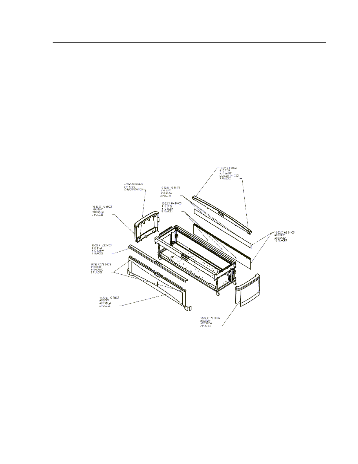
The internal components of the scanner are safely secured by a number of
panels, including the scanner's tabletop.
Figure 2-9. PRODIGY System Exploded View of External Covers and
associated hardware
• The front and side panels are secured by screws from the inside.
• The rear panel is se cured by screws from the outside.
• The table top is screwed down from the top.
Note: Prima ry Service access to the electronics of the scanner is
through the table to p.
This document contains confidential or proprietary information of GE-Lunar Corp. Neither the document nor the information therein is
to be reproduced, distributed, used or disclosed, either in whole or in part, except as specifically authorized by GE-Lunar Corp.
PRODIGY Service Manual (Rev C - 2000) System Overview 2-33
Page 28

• The Detector electronics (in the scan arm) are secured by an upper and
lower shroud, held in pl ac e by scre w s.
• Each metal panel is grounded to the electronics pan.
It is not usually necessary to remove the front and back panels for most
service needs. However, if access is needed to the Front and Rear
Longitudinal Car riages, these can be removed.
The back panel is secured by hex socket head -head screws and must be slid
out of the way, for it is between the Arm Column and the frame.
If access is needed to the detector, Transverse Limit Switches or the other
components mounted above in the arm, the covers of the arm must be
removed.
• The upper scan arm shroud can be removed by loosening the two
screws holding it in place (on the back of the arm column) and tipping it
forward.
• The lower cover is held in place by four screws, two in the front and two
in the back, be sur e to remove the ground wire for the metal portion of
the lower cover as well
This document contains confidential or proprietary information of GE-Lunar Corp. Neither the document nor the information therein is
to be reproduced, distributed, used or disclosed, either in whole or in part, except as specifically authorized by GE-Lunar Corp.
2-34 System Overview PRODIGY Service Manual (Rev C - 2000)
Page 29

2.1 Electronics
2.1.1 Cautions
PRODIGY I electronics use Negative Temperature Coefficient (NTC)
thermistors to limit the in rush current of the AC isolation transformer and the
Detector Mother Board. These devices have a high resistance when cold and
decrease in resist ance when warm.
PRODIGY electronics are static sensitive,
take static control precautions before
servicing scanner circuitry.
Figure 2-10. PRODIGY I NTC thermistor on the Primary Terminal Bl ock
• A cool down period of 30 seconds is required before power is turned on
on the system.
PRODIGY I ONLY: Failure to allow the
system to “cool down” may cause the
circuit breaker for the AC line to tri p and /
or the + 12VDC for the Detector Mother
Board (DMB) will not come up to +12 VDC.
Note: The error log entry "DMB Power Cycle observed" is an
indicator tha t the DC power to the Detector Mother Board has
been interrupted and the system should be powered down for
30 seconds to restore power to the Detector Mother Board.
PRODIGY I ONLY: The NTC’s can get hot - they
are located on the AC terminal block and on the
DC terminal bl ock be ca r eful w h en s ervi cin g t hes e
areas of the scanner.
2.1.2 Electronics Pan
This document contains confidential or proprietary information of GE-Lunar Corp. Neither the document nor the information therein is
to be reproduced, distributed, used or disclosed, either in whole or in part, except as specifically authorized by GE-Lunar Corp.
PRODIGY Service Manual (Rev C - 2000) System Overview 2-35
Page 30

The electronic c omponents of the PRODIGY are mount ed on the grounded
Electronics Pan which is horizontally fastened inside the frame.
Note: Append ix 2 A contains a la yout drawi ng of the Electr onics Pan
for PRODIGY I and PRODIGY II systems.
PRODIGY I Systems (System numbers DF+11999 and lower):
• There are four l ow-volt age linear DC power sup plies ( under 30V DC), and
two high-voltag e DC power s upplies (t o supply 7 6kV to the x -ray tube ) on
the pan.
• In addition to t he pow er su pp li es, t he e lec tro ni cs mou nt ing ch ass is h ol ds
four printed circuit boards, a stepper motor controller, the audible a larm,
an AC entrance/line filter/fuse holder, an isolation transformer and a
terminal strip for AC power distribution to the Host PC and peripherals.
PRODIGY II Systems (System numbers DF+12000 and greater):
• There is one low- voltage DC s witching power su pply (unde r 30VDC), and
one high-voltage D C power supply (x-ray generat or - supplies 76kV to
the x-ray tube) on t he pan.
• In addition to t he pow er su pp li es, t he e lec tro ni cs mou nt ing ch ass is h ol ds
one printed cir cui t bo ar d, a st ep per mot or c ont rol le r, and an A C en tran ce/
line filter/fuse holder.
2.1.3 Scan Arm
• The scan arm contains one high-voltage power supply (1000VDC / +12
VDC input) is located in the upper arm near the X- ray detector and
provides power to t he Detector Array.
• The scan arm also houses the detector and 5 associated printed circuit
boards, and a stepper motor contoller.
2.1.4 Power specifications
Leakage current
• Total System with Isolation Transformer: <100 microamperes.
• Scanner Table alone: <100 microamperes.
Scanner input power
• PRODIGY I ONLY: The scanner has 12 d ifferent nominal in puts: 100,
110, 115, 120, 125, 127, 200, 220, 230, 240, 250, and 254 VAC. During
installation, the scanner is configured for the nominal input which best
matches the voltage on site.
This document contains confidential or proprietary information of GE-Lunar Corp. Neither the document nor the information therein is
to be reproduced, distributed, used or disclosed, either in whole or in part, except as specifically authorized by GE-Lunar Corp.
2-36 System Overview PRODIGY Service Manual (Rev C - 2000)
Page 31

• PRODIGY II ONLY: The scanner can accept any AC input be tween 100
and 254 VAC.
• Voltage may fluctuate ±10% from the nominal value without a loss of
scanner performance.
• The nominal input (range of inputs) can be found on the system label.
• The rated power input is 1500 VA.
• The input power must meet IEEE 519-1992 for pow er quality and total
harmonic distortion (THD <5%).
Scanner output power (PRODIGY I system numbers DF+11999 and lower
only)
• The scanner has 3 different nominal out puts: 100, 120, 240 VAC.
• The nominal volt ag e outp ut of t he s cann er is show n o n the sys te m lab el .
• The computer and all peripherals which use the scanner output power
must be rated for this voltage.
• The maximum power output is 400 VA.
This document contains confidential or proprietary information of GE-Lunar Corp. Neither the document nor the information therein is
to be reproduced, distributed, used or disclosed, either in whole or in part, except as specifically authorized by GE-Lunar Corp.
PRODIGY Service Manual (Rev C - 2000) System Overview 2-37
Page 32

2.2 PRODIGY Block Diagrams
The block diagrams for the PRODIGY system follow:
2.2.1 PRODIGY I (System numbers DF+11999 and lower) Power Distribution Block Diagra m (AC ent ranc e)
Figure 2-11. PRODIGY I Power Distribution Block Diagram
This document contains confidential or proprietary information of GE-Lunar Corp. Neither the document nor the information therein is
to be reproduced, distributed, used or disclosed, either in whole or in part, except as specifically authorized by GE-Lunar Corp.
2-38 System Overview PRODIGY Service Manual (Rev C - 2000)
Page 33

2.2.2 PRODIGY System Block Diagram PRODIGY I System Block Diagram
Figure 2-12. PRODIGY I (systems DF+11999 and lower) Block Diagram
This document contains confidential or proprietary information of GE-Lunar Corp. Neither the document nor the information therein is
to be reproduced, distributed, used or disclosed, either in whole or in part, except as specifically authorized by GE-Lunar Corp.
PRODIGY Service Manual (Rev C - 2000) System Overview 2-39
Page 34

2.2.3 PRODIGY I Peripheral Configuration Block Diagrams
Figure 2-13. PRODI GY I (Systems DF+11999 and lower) Peripheral
Configuration Block Diagrams
This document contains confidential or proprietary information of GE-Lunar Corp. Neither the document nor the information therein is
to be reproduced, distributed, used or disclosed, either in whole or in part, except as specifically authorized by GE-Lunar Corp.
2-40 System Overview PRODIGY Service Manual (Rev C - 2000)
Page 35

2.2.4 PRODIGY II System / Power Block Diagram
Figure 2-14. PRODIGY II System / Power Block Diagram
This document contains confidential or proprietary information of GE-Lunar Corp. Neither the document nor the information therein is
to be reproduced, distributed, used or disclosed, either in whole or in part, except as specifically authorized by GE-Lunar Corp.
PRODIGY Service Manual (Rev C - 2000) System Overview 2-41
Page 36

2.3 PRODIGY Fusing
PRODIGY I (system numbers DF+11 999 and lower) Fuses
Fuse Rating Type*
F1 (Computer AC) T 2.0 AL 5x20MM
F2 (Computer AC) T 2.0 AL 5x20MM
F3 (+5, +/-12 VDC
PS (1))
F4 (+5, +/-12 VDC
PS (2))
F5 (+26VDC PS) T 2.5 AL 5x20MM
F6 (+28VDC PS) T 0.63 AL 5x20MM
F7 (+5, +/-12VDC
PS (1))
F8 (+5, +/-12VDC
PS (2))
F9 (+26 VDC PS) T 2.5 AL 5x20MM
F10 (+28 VDC PS) T 0.63 AL 5x20MM
MAX PCB F1 F 0.5 AL 1/4x1 1/4 in.
All fuses are 250V , low breaking capacity ( 25A minimum)
Table 2-1. PRODIGY I (Systems DF+11999 and lower) Fuses
T 1.25 AL 5x20MM
T 1.25 AL 5x20MM
T 1.25 AL 5x20MM
T 1.25 AL 5x20MM
PRODIGY II (systems DF+12000 and greater) Fuses
Fuse Rating Type
Condor PS
F1
Condor PS
F2
COndor PS
F3
All fuses are 250V , low breaking capacity ( 25A minimum)
Table 2-2. PRODIGY II (systems DF+12000 and greater) Fuses
This document contains confidential or proprietary information of GE-Lunar Corp. Neither the document nor the information therein is
to be reproduced, distributed, used or disclosed, either in whole or in part, except as specifically authorized by GE-Lunar Corp.
2-42 System Overview PRODIGY Service Manual (Rev C - 2000)
F3.15 AH 5x20 mm
F3.15 AH 5x20 mm
F3.15 AH 5x20 mm
Page 37

2.4 PRODIGY I (system numbers DF+11999 and lower) Single Board Controller
2.4.1 SBC Functions
The microprocessor-based Single Board Controller (SBC) provides overall
operation and con trol of the scan table.
Control Functions
• Control of x-ray source power supplies, and shutter / collimator in a fail
safe manner.
• Provides control signals for two external stepper motor drives (Centent)
to scan patient in a fail safe manner and senses limit switch actuation at
the limits of travel (via FOINK see 2.11).
• Controls the detector array (communicates with the Detector Mother
Board, section 2.10.2).
• Responds to exter nal scanner failure signals ( interrupts generated by
SBC, FOINK see 2.11, and Detector Mother Board see 2.10).
Communication
• Communicates with PC host via an optically isolated RS-422 interface.
• Collects data from the detector array.
2.4.2 SBC Reset
All SBC circuitry resets when the microprocessor resets. This is done during
power up, and can also be done over the communication port (via the host),
through connections to other circuit boards (especially the Detector Mother
Board, as a fail -safe shutdown), the by pressing the reset button on the SBC,
by pressing the Emergency Stop Button on the arm, or when a fault is
detected by the SBC or the FOINK (section 2.11.1).
Error Conditions Sensed by the SBC:
• Loss of Communications with the Detector Mother Board (DMB).
• Loss of Communications with the Host PC.
• Limit Switch tripped when shutter is open.
• Limit Switch depressed when commands are being sent.
• Failure in x-ray source kV programming
This document contains confidential or proprietary information of GE-Lunar Corp. Neither the document nor the information therein is
to be reproduced, distributed, used or disclosed, either in whole or in part, except as specifically authorized by GE-Lunar Corp.
PRODIGY Service Manual (Rev C - 2000) System Overview 2-43
Page 38

• Interrupt sent by FOINK
The DMB will reset the SBC if it detects an error.
Error Conditions of the DMB sensed by the SBC:
• PLD programming failure
• Loss of +5 or +12 VDC
• Loss of Communications with SBC
• Corrupt FIRMWARE
•FLASH RAM Failure
• DTR Reset button on the DMB is pressed
2.4.3 SBC / Host PC Interface
The SBC communicates with the Host PC via an RS-422 interface. This is a
serial connection capable of transmitting more data than a standard RS-232
port. As it is not a standard serial port a R S-485 card must be installed into
one of the Host P Cs expansi on slots an d the po rt must be configu red correct ly
for the PRODIGY t o opera te corr ectl y (see D XPC20 00 chapter 5 appen dices ).
This document contains confidential or proprietary information of GE-Lunar Corp. Neither the document nor the information therein is
to be reproduced, distributed, used or disclosed, either in whole or in part, except as specifically authorized by GE-Lunar Corp.
2-44 System Overview PRODIGY Service Manual (Rev C - 2000)
Page 39

2.5 PRODIGY II Combined Single Board Controller (cSBC) (systems DF+12000 an d greater)
The cSBC printed wiring board (PWB) is an eight layer rectangular board
measuring 7.400" x 8.100". The PWB is mounted in the via four mounting
holes located 1/4" from each corner and 2 additional interior mounting holes.
The components are p rimari ly s urface mount , wi th boar d co nnector s, headers
and a few single-style ICs being the only exceptions.
Four layers we re dedicated for routing layers. Sensitive s ignals were noted
and routed manu ally and isola ted f rom mor e power ful signals to r educe s ignal
interference and crosstalk on the same routing layer. The main power and
ground planes wer e s tacke d a dj ace ntly on th e c ent ral i nn er l aye rs t o inc re ase
inter-planar c apacitance thus reducing ground bounce and power suppl y
noise. Traces on the top and bottom layers were kept as short as reasonably
possible and tapped down to an internal trace layer through vias.
Component placem ent is arranged to separate analog from digital circuitry.
Further isolat ion was achieved by segmenting the power and ground planes
into analog and d igital secti ons an d denyi ng anal og/d igital plane over lap, th us
preventing digital noise from couplin g into the analog section. All scanner
control I/O is run via conn ectors locat ed on the +24V plane section. The +24 V
plane is fully optically isolated from both the analog and digital plane areas to
prevent motor noise from coupling int o the analog section, to prevent DC
switching noise from radiating on scanner cables, and to prevent ESD
presented at cable inputs from reaching the digital IC's.
2.5.1 cSBC System Architecture
The cSBC employs an Intel 80C251 micro-controller as its processor. This
processor provides 1K of on-board RAM and no on-board ROM. The
controller is clocked at 16 MHz using a crystal.
cSBC Memory Space
The cSBC is designed to support a JEDEC-standard, non-volatile FLASH
memory device up to 512K x 8 bits in size for code and f ixed data. The board
supports either 128K or 512K SRAM memory device as needed for program
volatile memory. Complete address decodi ng is provided via the MAX PLD,
the CBSC bus master, allowing the address space to be arbitrary an d
changed via the PLD code. The 80251 can address four 64K segments,
referred to as 0x00, 0x01, 0xFE and 0xFF as per Intel literature. The firmware
has the ability to map any FLAS H or SRAM seg ment t o any CPU segme nt via
SFR’s in the MAX PLD.
FLASH RAM
This document contains confidential or proprietary information of GE-Lunar Corp. Neither the document nor the information therein is
to be reproduced, distributed, used or disclosed, either in whole or in part, except as specifically authorized by GE-Lunar Corp.
PRODIGY Service Manual (Rev C - 2000) System Overview 2-45
Page 40

At startup the CPU executes the boots code which programs the FLEX PLD
and then maps in eithe r NT or Pro digy ru ntim e firmw are as appr opriat e based
on the most signif icant bit of the CCA REV register. To switch from boot code
to run code the firmware jumps to SRAM and executes a code snippet which
pages the boot code out of 0xFF and the desired f irmware into 0xFF. The
snippet then jumps from SRAM back to 0xFF to execute the firmware. A boot
jumper, JP4 is provided to optionally force the CPU to remain in the boot
code. When the boot jumper is installed the b oot code runs the host port at
115.2KB.
SRAM
The cSBC contains a single 128K x 8 bit SRAM which provides read/write
memory. The SRAM's segments are arbitrarily mapped to any CPU segment
by the CPU mapping registers.
2.5.2 cSBC Functions
The microprocessor -based Single Board Controller (cSBC) provides overall
operation and co ntrol of the scan table.
FLEX PLD Peripherals
The majority of s c anner related programmable logic functionality is contained
in the FLEX PLD, an Alt era EP F6024 AQC 20 8-3 de vic e. De vic e prog r ammi ng
is handled exclusively by the CPU. On each cold boot the CPU reprograms
the FLEX devices from an image stored in it's FLASH. As such a firmware
download of a new FLE X image is required to permanently upgrade the PLD
code.
The functional c omponents of the programmabl e logic are discussed in the
following subs ections. Polarity of operation can be inferred from bit names
and use of preceding slash for inverted logic bits.
Note that ports A-F are reloaded with default values at time of CPU reset and
remain in the default state until SCANNER_RESET has been cleared and
new values are wr it ten by the firm w a re. Defa ults for port F and all othe r
registers are invoked at power up only.
PORT A
Bit Name R/
W
0 trans_enable R/W 0 Transverse motor enable – low blocks trans motor pulses and
1 /trans_fwd R/W 0 Transverse motor direction control.
2 /shutter_open_ctrl R/W 1 Shutter solenoid control.
3 trans_lsw_override R/W 0 Transverse limit switch override – prevent limit switch contact
This document contains confidential or proprietary information of GE-Lunar Corp. Neither the document nor the information therein is
to be reproduced, distributed, used or disclosed, either in whole or in part, except as specifically authorized by GE-Lunar Corp.
Def. Description
forces Centent drive to standby current level.
from blocking step pulses at hardware level.
2-46 System Overview PRODIGY Service Manual (Rev C - 2000)
Page 41

4 long_enable R/W 0 Longitudinal motor enable – low blocks trans motor pulses and
forces Centent drive to standby current level.
5 /long_fwd R/W 0 Longitudinal motor direction control.
6 long_lsw_override R/W 0 Longitudinal limit switch override – prevent limit switch contact
from blocking step pulses at hardware level
7 /collimator_open_ctrl R/W 1 Collimator solenoid control.
This document contains confidential or proprietary information of GE-Lunar Corp. Neither the document nor the information therein is
to be reproduced, distributed, used or disclosed, either in whole or in part, except as specifically authorized by GE-Lunar Corp.
PRODIGY Service Manual (Rev C - 2000) System Overview 2-47
Page 42

PORT B
Bit Name R/
W
0 /trans_front_lsw R N/A Transverse front limit switch position.
1 /trans_back_lsw R N/A Transverse back limit switch position.
2 /long_foot_lsw R N/A Longitudinal foot limit switch position.
3 /long_head_lsw R N/A Longitudinal head limit switch position.
4 trans_count_eq[0] R N/A Set when transverse step counter equals zero.
5 long_count_eq[0] R N/A Set when longitudinal step counter equals zero.
6 /shutter_open_sense R N/A Shutter limit switch position.
7 /collimator_open_sense R N/A Collimator limit switch position.
Def. Description
PORT C
Bit Name R/
W
/long_rev_pos
0
R N/A Patient positioner (joystick) input.
Def. Description
/long_fwd_pos
1
/trans_rev_pos
2
/trans_fwd_pos
3
/hvps_ac_relay
4
/motor_fail_enable
5
ags_enable
6
/motor_power
7
R N/A Patient positioner (joystick) input.
R N/A Patient positioner (joystick) input.
R N/A Patient positioner (joystick) input.
R/W 1 Enable AC power to X-ray HVPS.
R/W 1 Arm logic to shutdown scanner if OMI inputs not sensed.
R/W 0 Enable detector automatic gain control feedback circuit.
R/W 1 Enable 24VDC to the stepper motor drives (a.k.a. Centents).
This document contains confidential or proprietary information of GE-Lunar Corp. Neither the document nor the information therein is
to be reproduced, distributed, used or disclosed, either in whole or in part, except as specifically authorized by GE-Lunar Corp.
2-48 System Overview PRODIGY Service Manual (Rev C - 2000)
Page 43

PORT D
Bit Name R/
W
flex_max_i/o_[0]
0
flex_max_i/o_[1]
1
flex_max_i/o_[2]
2
flex_max_i/o_[3]
3
flex_diag_3
4
pit_enable
5
flex_diag_1
6
/laser_on
7
R/W 0 Output signal to MAX PLD (diagnos tic use only).
R/W 0 Output signal to MAX PLD (diagnos tic use only).
R/W 0 Output signal to MAX PLD (diagnos tic use only).
R/W 0 Output signal to MAX PLD (diagnos tic use only).
R/W 0 Firmware controlled diagnostic LED.
R/W 0 Enable Programmable Interval Timer output pulses.
R/W 1 Firmware controlled diagnostic LED.
R/W 1 Patient locator laser control.
PORT E
Bit Name R/
W
low_range_dac
0
R/W 0 Switches mA DAC from 2.048V to 0.500V reference.
Def. Description
Def. Description
trans_motor_accel
1
low_range_adc
2
long_motor_accel
3
hvps_vendor_id
4
iq_hvps
5
/hvps_enable_status
6
/power_up
7
R/W 0 Enables motor interrupt on every micro step.
R/W 0 Switches ADC from 5.000V to 0.500V reference.
R/W 0 Enables motor interrupt on every micro step.
R N/A For 7681 supply, 0 = Spellman, 1 = Bertan.
R N/A Set by resistor placement to indicate 0311/0312 supplies.
R N/A Enable status monitor from 7681 supply.
R N/A Set to indicate cold boot.
This document contains confidential or proprietary information of GE-Lunar Corp. Neither the document nor the information therein is
to be reproduced, distributed, used or disclosed, either in whole or in part, except as specifically authorized by GE-Lunar Corp.
PRODIGY Service Manual (Rev C - 2000) System Overview 2-49
Page 44

PORT F
Bit Name R/
W
/motion_fail_enable
0
long_motor_fail_axis
1
/hvps_enable
2
flex_diag_2
3
/arm_estop_sense
4
spare_jmp_[1]
5
spare_jmp_[0]
6
cpu_p1_2
7
R/W 1 Arm scanner shutdown if OMI pulses w/o step pulses.
R/W 0 Motor fail circuitry axis control, clear for transverse.
R/W 1 Enable output to 7681 supply.
R/W 0 Firmware controlled diagnostic LED.
R N/A Emergency stop sense bit.
R N/A Unused input, resistor or jumper selectable on CCA.
R N/A Unused input, resistor or jumper selectable on CCA.
R N/A Firmware controlled diagnostic LED.
PORT G
Bit Name R/
W
adc_mux_[0]
0
R/W 0 ADC analog MUX input selection control bit.
Def. Description
Def. Description
adc_mux_[1]
1
adc_mux_[2]
2
adc_mux_[3]
3
adc_mux_enable
4
8ms_clock
5
unused
6
unused
7
R/W 0 ADC analog MUX input selection control bit.
R/W 0 ADC analog MUX input selection control bit.
R/W 0 ADC analog MUX input selection control bit.
R/W 0 ADC MUX output enable control.
R/W 0 Clock output provided to MAX PLD.
N/A N/A For expansion.
N/A N/A For expansion.
2.5.3 TRANS / LONG MOTOR Control and Status
Dual axis stepper motor control is provided entirely by the FLEX PLD . To
make a typical move the firmware loads a starting velocity into the 16 bit
VELOCITY register, the total number of steps for the move into the 16 bit
TARGET register, and step at which to next interrupt the CPU into the 16 bit
STEP register. Velocity is in ter ms of per iods of th e 2.0MHz fundamen tal clock
per micro step pulse to the stepper drive. The drives provide 10 micro steps
per full step. The firmware can track move status by reading the 16 bit READ
register.
This document contains confidential or proprietary information of GE-Lunar Corp. Neither the document nor the information therein is
to be reproduced, distributed, used or disclosed, either in whole or in part, except as specifically authorized by GE-Lunar Corp.
2-50 System Overview PRODIGY Service Manual (Rev C - 2000)
Page 45

As part of the setup for a move the host and/or fi rmware must enable the
motors via the /motor_power, trans_enable, and long_enable outputs and
setup the trans_lsw_override, long_lsw_override, /motion_fail_enable, /
motor_fail_ena ble, and l ong_m otor_f ail_ axis outputs as desire d. I f the syste m
is in scanner reset for any reason the FLEX PLD will over-ride the /
motor_power output and prevent 24V power from reaching the motor drives.
Addressing for t he motor control interface is provided below.
2.5.4 AGS ROLL
This is a read only 8 bit register which returns the count of AGS roll-over
events since the previous read of the regis ter. The AGS roll counter is reset
on read only - it is not tied to the PIT's sample clock.
2.5.5 AGS DAC
This port provides R/W access to the AGS circu it's 8 bit U/D counter. The
counter is tied via a dedicated 8 bit bus to the AGS DAC. The DAC's analog
voltage is tied t o the gain control input of the variable gain amplifier (VGA)
used to control gain of the detector input signal. As such the firmware can
read this counter to determine the current DAC voltage level and hence gain
level. If ags_enable is low this port gives t he firmware direct contr ol of the
AGS DAC as a parallel R/W device. If ags_ena ble is high, the firmwar e can
write to the port but the DAC will continue to respond to UP/DOWN requests
from the AGS DCA circuitry and hence quickly return to the AGS current
operating voltage.
HE/LE COUNTERS
These read only ports provide access to the 16 bit e vent counters which are
incremented ea ch time the DCA circuitry detects an input pulse within the HE
or LE windows (as defined by the LEL, LEH, HEL, and HE H DAC settings).
These counters are read in two 8 bit bus cycles, MSB then LSB. The event
counters themsel ves cons ist of a count ing eleme nt and a bus el ement. On the
rising edge on the PIT output pulse the counting elements are latched to the
bus element. The PIT output is also tied to CPU external INT 1 and as such
the firmware interrupt handler then has until the next rising PIT edge to read
the counters before the bus elements are la tched over with the next sample
count and data is lost.
PIT MSB/LSB
This document contains confidential or proprietary information of GE-Lunar Corp. Neither the document nor the information therein is
to be reproduced, distributed, used or disclosed, either in whole or in part, except as specifically authorized by GE-Lunar Corp.
PRODIGY Service Manual (Rev C - 2000) System Overview 2-51
Page 46

The PLD provides a programmable interval tim er (PIT) to the CPU. The PLD
prescales it's i nput clock to generate a PIT base clock of 100KHz. The CPU
writes a 2 by te word to the PIT rel oad regi ster MSB /LSB. T he CPU the n raise s
the pit_enable bit to start the timer. In response to the rising edge on the
pit_enable, the PIT loads the reload word in to it's counting element and
begins counting down. When the count rolls und er the PIT asserts /
SAMPLE_INT, reloads the counting element, and begins another count down
sequence. The /SAMPLE_INT line is tied internally to the HE and LE event
counters and causes a synchronous latch of both counting elements. The /
SAMPLE_INT line is also tied to the processor's 2nd external interrupt line, /
INT1. The CPU interrupt handler reads the latched event counters and ships
the data to the host.
2.5.6 SCANNER RESET
The scanner reset register is used to provid e failsafe shutdown operation of
the scanner. A falling edge on any of the inputs to this register will latch the
current value of th e re gister and drop t he / SCAN_FAIL_ANY output. The MAX
PLD latches the mast er res et regi st er a nd rai ses C PU_RE SET i n r e sponse to
the falling edge on /SCAN_FAIL_ANY. The MAX PLD also provides
SCANNER_RESET as the logical OR of CPU_RESET and!/
SCAN_FAIL_ANY. The FLEX PLD uses it's SCANNER_RESET input as the
enable bit to the tri-state buffer s used to drive all safety c ritical output lines
including shutter control, HVPS relay control, motor relay control, etc. As such
the scanner is locked into a fail-safe mode whenever SCANNER_RESET is
asserted.
The MAX's master reset register will remain latched until the nex t rising edge
on the HOST_RTS input. When the cSBC is latched into reset by a scanner
error it will remain in CPU reset until the host drops the RTS line and reasserts it. It will rema in in sc anner re set unti l t he CPU r eads th e scann er r eset
register following the next raising edge of the RTS line at which the condition
causing the /SCAN _ FAIL_ANY has bee n cl ea re d. The firm w a re pa s ses the
value of the reset registers to the host to allowing the host to display
appropriate error messages to the operator. The host will be unable to
perform any scanner related operations until the SCANNER_RESET has
been cleared. Red diagnostic LED's (see 2.5.33) are provided for both
scanner and CPU reset lines. The CPU reset lin e is tied to the host CTS
output such that the host se es a CTS e vent when t he cSBC en ters C PU reset.
The host code provides a CTS event handler which reads the reset registers
and prompts the use r accordingly.
This document contains confidential or proprietary information of GE-Lunar Corp. Neither the document nor the information therein is
to be reproduced, distributed, used or disclosed, either in whole or in part, except as specifically authorized by GE-Lunar Corp.
2-52 System Overview PRODIGY Service Manual (Rev C - 2000)
Page 47

The firmware can also initiate a reset sequence in response to fatal error
conditions by writing a 'death code' to the suicide reset register. Resets can
also be initiated by the manual push button on the cSBC and by a low 5VDC
power conditio n as sens ed by th e MAX70 5 superv isor. The scanner regis ter is
also latched at the end of read cycles such that curr ent status can be
ascertained by a double read. A bit map of the scanner reset register is
provided belo w
Bit Name R/
W
0/
thermostat_open_sense
1 /external_estop_sense R N/A Emergency stop input from external options block.
2 /dc_power_fail R N/A Loss of one or more of +5VDC,+12VDC,-12VDC, or +24VDC.
3 /long_motor_fail R N/A Motor failure detected on longitudinal axis.
4 /trans_motor_fail R N/A Motor failure detected on transverse axis.
5 /dmb_error R N/A DMB dropped it’s CTS indicating a DMB reset event.
6 /motion_fail R N/A OMI pulses detected without step pulse (manual arm motion).
7 /watchdog_reset R N/A Watchdog time-ou t indicates firmware crash.
R N/A Tube head thermostat over temperature.
Def. Description
2.5.7 GE-LUNAR Model 7861 X-ray Generator Errors
The HVPS error re gister is used to monitor the status of the 7681 X-ray
source HVPS. If the register value is not equal to 0xF when /hvps_enabl e is
low, the FLEX will raise the HVPS_ERROR_INT output to the MAX PLD. The
MAX PLD latches t hi s i nt o t he II R regi st er an d is sue s an inte rr u pt to the C PU.
As such status of the HVPS is monitored when the unit is enabled. The
handler for HVPS interrupt reads this register to determin e the cause of the
interrupt. The HVPS register is also latched at the end of read cycles such
that current status can be ascertained by a double read. A bit map of the
register is provided below.
Bit Name R/
W
0 /hvps_error_0 R N/A Error code bit from 7681 supply.
1 /hvps_error_1 R N/A Error code bit from 7681 supply.
2 /hvps_error_2 R N/A Error code bit from 7681 supply.
3 hvps_enable_status R N/A Set when /hvps_enable == /hvps_eanble_status
4 Unused N/A N/A Expansion room.
5 Unused N/A N/A Expansion room.
This document contains confidential or proprietary information of GE-Lunar Corp. Neither the document nor the information therein is
to be reproduced, distributed, used or disclosed, either in whole or in part, except as specifically authorized by GE-Lunar Corp.
Def. Description
PRODIGY Service Manual (Rev C - 2000) System Overview 2-53
Page 48

6 Unused N/A N/A Expansion room.
7 Unused N/A N/A Expansion room.
2.5.8 DC FAIL
The DC fail error register latches the status of the DC power monitors at the
time of reset. If sc anner reset code indicates /dc_power_fail the firmware can
read this register to iden tify the specifi c DC source fa ilur e. The reg iste r is also
latched at the end of read cycles such that current status can be ascertained
by a double read.
Bit Name R/
W
0 /plus_scanner_fail R N/A Loss of +24V power input.
1 /plus_analog_fail R N/A Loss of +12V power input.
2 /minus_analog_fail R N/A Loss of -12V power input.
3 Unused N/A N/A Expansion room.
4 Unused N/A N/A Expansion room.
5 Unused N/A N/A Expansion room.
6 Unused N/A N/A Expansion room.
7 Unused N/A N/A Expansion room.
Def. Description
2.5.9 DCA / AGS / BIAS DAC's
The cSBC uses a sing le 10 b it oc ta l DA C, t he Lin ear Technology LTC1660, to
generate the A GS a nd DA C wi nd ow r ef eren ce vo lt ag es an d the bia s pr og ram
voltage. The DAC u tilize s a serial interfa ce and as suc h is not ac cessed with a
traditional CPU write cycle. To load the device the firmware writes to the DAC
address listed a bove, in response to which the MAX drops the /CS line to the
device. The firmware then manipulates the local serial bus clock and data
lines to load the DAC setting. The desired DAC channel address in encoded
into the first 4 bits of the output data word. A read is then made to the DAC
address, in response to which the MAX raises the /CS line. See device data
sheet and analog section below for further DAC details.
This document contains confidential or proprietary information of GE-Lunar Corp. Neither the document nor the information therein is
to be reproduced, distributed, used or disclosed, either in whole or in part, except as specifically authorized by GE-Lunar Corp.
2-54 System Overview PRODIGY Service Manual (Rev C - 2000)
Page 49

2.5.10 KV/mA DAC
The cSBC uses a single 12 bit dual DAC, the Linear Technology LTC1454, to
generate the HVPS kV and mA program voltages. The DAC utilizes a serial
interface and as such is not accessed with a traditional CPU write cycle. To
load the device the firmware writes to the DAC address listed above, in
response to which the MAX drops the /CS line to the device. The firmware
then manipulates the local serial bus clock and data lines to load the DAC
setting. Both DAC channels must be written together, CHA (kV) first followed
by CHB (mA) in a 24 bit stream pa c ke t. A read is then ma de to th e DA C
address, in response to which the MAX raises the /CS line. See device data
sheet and analog section below for further DAC details.
2.5.11 ARC/FIL DAC
The cSBC uses a single 10 bit dual DAC, the Linear Technology LTC1661, to
generate the HVPS filament limit and arc detect threshold voltages. The DAC
utilizes a serial interface and as such is no t accessed with a traditional CPU
write cycle. To load the device the firmware writes to the DAC address listed
above, in response to which the MAX drops the /CS line to the device. The
firmware the n m ani pula te s t he l ocal ser i al bu s c lo ck and da ta l ines to l oad t he
DAC setting. T he de sir ed DAC c hanne l add ress in e ncoded into the f ir st 4 bits
of the output data w ord. A read is then made t o the DAC addr ess, in resp onse
to which the MAX raises the /CS line. See dev ice data sheet and analog
section below for further DAC details.
2.5.12 PEAK DAC
The cSBC uses a 12 bit DAC, the Linear Technology L TC8043, to generate
the detector peak gain voltage. The DAC utilizes a serial interface and as
such is not accesse d with a trad itiona l CPU wr ite cyc le. To load the device the
firmware manipulates the local serial bus clock and data lines to output load
the DAC setting and then perf orms a write/read cycle to the DAC address
listed above to pulse the DAC's load line low. See device data sheet and
analog section below for further DAC details.
2.5.13 MAX PLD Peripherals
The programmable logic section is based on an Al tera MAX
EPM7128STC100-15 device. The configuration pins for this device are t aken
to a JTAG style 10 pin hea der to al low fo r in-ci rcui t progr ammin g of the de vice
from the Altera By te-Blaster. The MAX device is FLASH based (non-volatile)
and is programmed at the time of CCA assembly. The functional components
of the programmabl e logic are discussed in the following subsections.
This document contains confidential or proprietary information of GE-Lunar Corp. Neither the document nor the information therein is
to be reproduced, distributed, used or disclosed, either in whole or in part, except as specifically authorized by GE-Lunar Corp.
PRODIGY Service Manual (Rev C - 2000) System Overview 2-55
Page 50

2.5.14 Interrupts
The CPU's interrupt capacity is effectively increased by running several
interrupt signals to a register in the MA X PLD and tying the register output to
the CPU external INT 0 input. Th e firm war e in te rrup t ha n dl er for INT 0 then
reads this regi ster to identify the sour ce of the interrupt and handles it
accordingly. The firmware then writes a bit masked '1' back to the IIR to clear
the bit of the interrupt it has serviced (the R/C in the table stands for READ/
CLEAR).
Bit Name R/
W
0 HOST_UART_INT R/C N/A Host UART interrupt.
1 DEBUG_UART_INT R/C N/A Debug UART interrupt.
2 DMB_UART_INT R/C N/A DMB UART interrupt.
3 HVPS_ERROR_INT R/C N/A HVPS error interrupt.
4 8mS_CLOCK R/C N/A 8ms clock tick interrupt from FLEX PLD.
5 POWER_FAIL_INT R/C N/A Power down pending in 5ms interrupt from DC supply.
6 Unused N/A N/A Expansion room.
7 Unused N/A N/A Expansion room.
Def. Description
2.5.15 MASTER RESET
The master reset regi st er w il l for ce a CPU and sc ann er r ese t condi t ion on the
falling edge of any of its listed inputs. The contents of the register wil l be
latched at the ti me of reset such that when the CPU n ext comes out of reset
the firmware can read the register to determi ne what caused the preceding
reset and report the ap p rop ri ate co de to th e ho s t. If th e res e t was ca use by
the CPU_RST_WR inpu t, th e sui cid e r ese t regi st er con ta in s the s pec ific err or
code. If the reset was cause by the /SCAN_FAIL_ANY input, th e scanner
reset register contains the specific error code.
The CPU and scanner resets will remain latched until the next rising edge of
the RTS input. At this time the CPU reset wil l be cleare d if /PO WE R _ RES ET
bit is not asserted and the scanner reset will be cleared if /SCAN_FAIL_ANY
is high.
This document contains confidential or proprietary information of GE-Lunar Corp. Neither the document nor the information therein is
to be reproduced, distributed, used or disclosed, either in whole or in part, except as specifically authorized by GE-Lunar Corp.
2-56 System Overview PRODIGY Service Manual (Rev C - 2000)
Page 51

Bit Name R/
W
0 /POWER_RESET R N/A MAX705 supervisor detects VCC < 4.65V.
1 /HOST_RTS R N/A RTS reset request from host via comm line.
2 /MANUAL_RESET R N/A Push button pressed.
3 Unused R N/A Expansion room, reads as ‘1’.
4 Unused R N/A Expansion room, reads as ‘1’.
5 Unused R N/A Expansion room, reads as ‘1’.
6 CPU_RST_WR R N/A Write to the suicide register, read suicide reg for error code.
7 /SCAN_FAIL_ANY R N/A Scanner reset register latched, read scanner reg for error code.
Def. Description
2.5.16 SUICIDE RESET
The CPU Reset SFR is a byte register into which th e CP U can write a failure
code. In response to the wri te th e M AX PL D will store th e fa ilu re co de and
assert the CPU_RE SET line. The CPU_RESET line will be released on the
next rising edge of the host RTS, at whi c h time the CPU will be able to read
the bit code from this SFR to determine the cause of the previous reset.
2.5.17 MISC OUT
The misc. output register is used to control the misc. output functions listed in
the following table.
Bit Name R/
W
0 Unused N/A N/A Expansion room.
1 MAX DIAG_2 R/W 0 Firmware controlled diagnostic LED.
2 DMB HWPT R/W 0 Enable direct connect of host and DMB XCVR’s, bypassing
3 RESET OVERRIDE R/W 1 Enable override of CPU_RESET sign al. Set to 1 on po wer-up such
4 Unused N/A N/A Expansion room.
5 Unused N/A N/A Expansion room.
6 Unused N/A N/A Expansion room.
7 Unused N/A N/A Expansion room.
Def. Description
UART’s, for maximized scan data bandwidth DMB to host.
that firmware can load the FLEX PLD at power-up regardless of
the host RTS state.
This document contains confidential or proprietary information of GE-Lunar Corp. Neither the document nor the information therein is
to be reproduced, distributed, used or disclosed, either in whole or in part, except as specifically authorized by GE-Lunar Corp.
PRODIGY Service Manual (Rev C - 2000) System Overview 2-57
Page 52

2.5.18 MISC IN
The misc. output register is used to control the misc input functions listed in
the following table
Bit Name R/
W
0 BOOT JUMPER R N/A JP4, placed to force firmware to remain in boot code.
1 CPU_P1_2 R N/A Input from CPU port 1, pin 2 (diagnostic use only).
2 Unused N/A N/A Expansion room.
3 Unused N/A N/A Expansion room.
4 Unused N/A N/A Expansion room.
5 Unused N/A N/A Expansion room.
6 Unused N/A N/A Expansion room.
7 Unused N/A N/A Expansion room.
Def. Description
2.5.19 Stepper Motor Control
The stepper motors use the same interface desi gn as used on IQ and Prodigy.
The FET exhibits a lower voltage drop and hence provides more available
power at the drives for a given source voltage - e ssentially recovering the
voltage lost in drop ping the D C supp ly fr om t he 26V u sed on IQ /Prod igy t o the
24V which is readil y available in commercial switchers. Diodes are placed in
series on the Centent power lines to prevent back EMF generated when the
arm is moved manu ally from reachin g th e 24 V pl anes and damagi ng the
cSBC. A dual FET circuit is used to minimize the voltage drop on the 24V
plane due to in-rush current when the motors are enabled. A circuit in the
FLEX implements a 2 st ag e tur n on when t he fi r mwar e lo wers /mot o r_ena bl e.
Q15 is enabled firs t to provide 24V to the Centents through R381 and R384,
thus limiting the in-rush current. After the current pulse has stabilized Q14 is
enabled to bypass the inrush limiting resistors. Q15 is then disabled and the
motors are at full power. An PTC is provided on the source of Q15 such that
the current limiting resistors will not be smoked if Q15 is inadvertently left
enabled.
This document contains confidential or proprietary information of GE-Lunar Corp. Neither the document nor the information therein is
to be reproduced, distributed, used or disclosed, either in whole or in part, except as specifically authorized by GE-Lunar Corp.
2-58 System Overview PRODIGY Service Manual (Rev C - 2000)
Page 53

2.5.20 OMI Input
The optical mot ion inte rru pt (OMI) sub-sys tem con nects to the transve rse an d
longitudinal OMI CCA's. The OMI CCA's are located on the far end (the gear
end farthest from the motor) of each drive axis. When the axis is in motion a
small toothed wheel spins through the OMI opto's beam and pulses are
sensed back on the cSBC. In this manner the system can sense a drive
circuit, motor, or belt failure which might otherwise result is a concentrated
exposure point during a patient scan. The OMI in puts are similar to those
used on the DPX-IQ. 74LS14's are added for hysteresis which provides a
clean direct int erface to the PLD. As on Prodigy, logic in the FLEX PLD is
used to qualify the CH A and CH B inputs into a single 'valid motion' output.
Based on the phases of the square wave inputs on CH's A&B , the FLEX is
able to sense a change in direction. The circuit provides hysteresis to reject
false motion inputs r esu lti ng fr o m scan ner vib r atio n wh en a whee l edg e st ops
in the center of the opto beam at the end of a move.
2.5.21 Pati ent Positioners
Four optically isolated inputs are provided for patient positioning. These are
used by the firmware to implement a joystick mode which is used in
conjunction with the laser to position the X-ray beam as desired over the
patient immediately prior to a scan. 74LS14 inverters are used to provide
hysteresis and isolate the FLEX PLD inputs from the slow rise times of the
opto output signals.
2.5.22 Limit Switches
Four optically isolated inputs are provided for limit switches. These are used
by the firmware t o define the transverse and longitudinal table limits. 74LS14
inverters are use d to provid e hysteres is and isol ate the FL EX PLD inpu ts from
the slow rise times of the opto output signal s.
2.5.23 X-ray Source Control / Mechanical Interlocks
The cSBC is designed such that a high on the scanner reset net disables all
scanner functi onality and assures a know, fail safe, s tate. All scanner control
outputs are driven by the FLEX PLD. The FLEX outputs drive the low side of a
PS2501 opto coupl er emitter. The far side of all these opto circuits are
configured such that the opto has to be energized for the scanner function to
be active. As such the FLEX has to sink current to energize the opto and
activate the desired scanner functi on. Internally the FLEX code defines these
outputs as tri-st ate buffers, each of which has their enable line tied to the
scanner reset net. As such a scanner reset wil l force all these FLEX scanner
outputs to a high impedance state, de-energizing the opto's and di sabling the
scanner.
The FLEX device is SRAM based and hence must be reprogr ammed by the
CPU at power up. When the device is not programmed all I/O pins default to
the high impedance state. As such the scanner will also be in a fail safe state
when the FLEX is not progra mmed. The CPU po rt 1, pin 2 al so runs di rectly to
the FLEX's ENABLE pin.
This document contains confidential or proprietary information of GE-Lunar Corp. Neither the document nor the information therein is
to be reproduced, distributed, used or disclosed, either in whole or in part, except as specifically authorized by GE-Lunar Corp.
PRODIGY Service Manual (Rev C - 2000) System Overview 2-59
Page 54

The cSBC provide a failsafe mechanism independent of the programmable
logic via the +5V_IO circuit. If one or more of either the E-stop, external Estop, or tube thermostat is open, the FET driving the +5V_IO net from the
+5VDC plane will be disabled. The +5V_IO net prov ides power to the emitter
anode of all opto's w hic h dri ve c r itic al scan ne r fun ctio ns. As suc h t he s can ner
will enter a failsafe state in response to these mechanical interlocks, even in
the event of a PLD device failure. The +5V_IO FET will also be disabled by
either a HOST_RTS or CPU_RESET.
2.5.24 Shutter / Collimator Drive
The shutter and colli mator solenoi d drive circuit s are the same as that used on
Prodigy I. The FLEX dr ives an isolation opto which in turn switches a pair of
FET's to control solenoid current. The f irst FET is used for an ini tial 'hard hit'
on open commands. It p resents 24V directly to the solenoid for several
hundred msec's, resulting in a large initial current pulse to the sol enoid. The
second FET provi des t he 'ho ld' cu rrent throu gh a p air of curre nt l imit ing pow er
resistors. The hold FET is tied directly to the /shutter_open_ctrl bit. Note that
the collimator dr ive i s popul ated o nly for NT -A an d IQ upgrad es whic h use the
old style IQ coll imator assembly. The nominal values of the power resistors is
changed betwee n the NT and Prodigy II BOM's to support both t he traditional
linear solenoi d of IQ, and the rotary solenoid of Prodigy. A jumper or DNP'd
resistor is used to drive the IQ_SHUTTER line to the FLEX such that both
mechanical an d op ti c al shut t er li mi t sw i tc h es are sup p ort ed .
2.5.25 End of Exposure Alarm
An on-board end of exposure alarm is provided. The alarm chosen is the
board mount equiv alent of that used on Prodigy I.
2.5.26 Panel LED's
The 4 panel LED's, power on, X-ray on, source exposed, and laser on, are all
driven PS2501-2 opto's through 750R0 / 1W current limiting resistors.
2.5.27 HVPS Cont rol
The HVPS analog control interface is designed to provide maximum
performance at min imum cost. A single, 16 channel multiplexed, 16 bit, high
accuracy, ADC is used in conjunction with several lower cost, lower bit
resolution DA C's. Abso lute acc uracy of DAC's is poor but erro rs are ca librated
out by the f i rmw are w hi ch mon ito rs t he ac tu al D AC ou tp ut v ia t he A DC. I n th is
scenario DAC integral non-linearity (INL) specs are not important, sufficient
differential non-linearity (DNL) is all that is required. Serial DAC's and ADC's
are chosen to conserve board space and simplify routing. Serial parts are
typically also lower cost as their maximum band width is limited by the serial
baud rate.
The HVPS AC is enab led via a relay controlled by the cSBC. The line is
primarially us ed to di sa ble the H VPS by r emov in g the A C to t he HVPS vi a the
relay. AC Power to th e HVPS can be left on for up to one hour after
generation of x-r ays to prevent AC cycling between concurrent scans.
This document contains confidential or proprietary information of GE-Lunar Corp. Neither the document nor the information therein is
to be reproduced, distributed, used or disclosed, either in whole or in part, except as specifically authorized by GE-Lunar Corp.
2-60 System Overview PRODIGY Service Manual (Rev C - 2000)
Page 55

A jumper and/or DNP'd resistor pad is provide to drive the IQ_HVPS line,
which the firmware reads to determine which HVPS it is intended to operate.
The PWB provides lem o styl e conne ctor pa ds for us e with t he tra diti onal 0311/
0312 HVPS and MAX CCA. For the 7681 HVPS the lemos are DNP'd and a
single DB-25 connector is used to control the HVPS. Tranzorb pa ds are
provide on the PWB and are expected to be populated only if deemed
necessary by EMC t esting. A n opto bank is also provide d to suppor t the dig ital
interface to the 7681. See Lunar dwg 7681-SP C for details.
2.5.28 ADC
The Burr Brown ADS8320 16 bit, serial, single channel ADC was chosen for
the cSBC for its high resolution, and excellent accuracy.
An Analog devices AD 586 +5V voltage reference is used. The part was
selected for it low noise and high accuracy
Overall the ADC and reference give the cSBC +/-5mV analog accuracy 11.2
DAC's
A single LTC1454 12 bit, serial, dual channel, DAC is used to provide the kV
and mA program voltages. The part was chosen for it low cost, ready
availability at nati onal distr ibutor s, and e xcell ent DNL speci fica tions. The DAC
is used in the x2 configuration such that the full scale output is twice the
reference voltag e . Voltage output s feed ba ck to th e ADC M UX su c h that
firmware can calibrate out DAC INL errors.
A single LTC1661 10 bit, serial, dual channel, DAC is used to provide the arc
threshold and f ilame nt cur rent l imit input volta ges t o the ne w 7681 HVPS. T he
part was chosen for it low cost, ready availability at national distributors, and
reasonable DNL specifications. Voltage outputs are not fed back to the ADC
MUX as high accuracy is not required on these threshold inputs.
2.5.29 mA Low Range
To support future scan modes , an mA l ow r an ge ci rcui t is p rovi ded . Th e FLE X
PLD provides a contr ol bit by which the firmware can switch the mA DAC
reference volta ge from 2.048 V to 0.5V, hence decreasing the LSB si ze, hence
allowing the firmware to take smaller voltage steps when ramping to low uA
settings. A second control bit is provided to switch the ADC from 5.0 to 0.5V
reference.
2.5.30 Detector Interface
The cSBC provides a RS-422 communications post to the Detector Mother
Board. The CSBC does not participate in any Detector data manipulation, all
analysis and Detector control is performed at the DMB.
This document contains confidential or proprietary information of GE-Lunar Corp. Neither the document nor the information therein is
to be reproduced, distributed, used or disclosed, either in whole or in part, except as specifically authorized by GE-Lunar Corp.
PRODIGY Service Manual (Rev C - 2000) System Overview 2-61
Page 56

2.5.31 Communications Ports Host RS-422 Port
The host I/O port provides optical isolation per medical leakage requirements
of EN 60601-1-1, Annex BBB, section 7. QT's 6N136 opto's are used to
provide the required 115.2KB operational band width and the required 2500
Vrms standoff at a reasonable price. Opto inputs and outputs are routed
through the MAX PLD to suppor t th e hardwa re pass though mode to the DMB .
A DB-9 female connector is provided on the host side of the isolation barrier.
RS-232 is support ed by populating the XCVR U26. RS-422 is supported by
U21 and U37, the RS-422 XCVR's. A simple charge pump circuit is used to
generate +5V_ ISO on the host side of the barrier. Prodigy II will populate the
RS-422 section and run at 115.2KB.
2.5.32 Debug RS-232 Port
The debug port is provided such that the firmware can echo status messages
and other informat ion to a dumb ter minal to support debuggi ng, de velopm ent,
testing, and servicing. The port is fu lly driven by a 16550 compatible UART is
fully connected to a DB-9 header using the standard PC comm port pinout.
The firmware can be configured to accept input from the debug port if
required. The port is expected to be depopulated in the final product ion BOM
to minimize cost.
2.5.33 Diagnostic LED's
16 diagnostic LED's are provided by the cSBC. Functionality is liste d below
LEDColor Function Description (status indicated when lit)
D13 Green +24V +24V DC input from supply present.
D14 Green +12V +12V DC input from supply present.
D15 Green -12V -12V DC input from supply present.
D7 Gre en +5V +5V DC input from supply present.
D16 Red FLEX CONFIG FLEX PLD not programmed.
D20 Red CPU RESET CPU in reset mode.
D19 Red SCANNER RESET Scanner in reset (failsafe) mode.
D27 Red AGS ROLL AGS roll over or under detected.
D29 Amber FLEX DIAG 1 Diagnostic LED for misc use by firmware, control reg in FLEX.
D31 Amber FLEX DIAG 2 Diagnostic LED for misc use by firmware, control reg in FLEX.
D22 Amber MAX DIAG 2 Diagnostic LED for misc use by firmware, control reg in MAX.
D28 Amber TRANS OMI Valid transverse motion sensed by OMI circuitry.
This document contains confidential or proprietary information of GE-Lunar Corp. Neither the document nor the information therein is
to be reproduced, distributed, used or disclosed, either in whole or in part, except as specifically authorized by GE-Lunar Corp.
2-62 System Overview PRODIGY Service Manual (Rev C - 2000)
Page 57

D22 Amber LONG OMI Valid longitudinal motion sensed by OMI circuitry.
D25 Amber HE COUNT Valid high energy photon event sensed by DCA circuitry.
D23 Amber LE COUNT Valid low energy photon event sensed by DCA circuitry.
D21 Amber HVPS ENABLE 7681 HVPS enabled.
This document contains confidential or proprietary information of GE-Lunar Corp. Neither the document nor the information therein is
to be reproduced, distributed, used or disclosed, either in whole or in part, except as specifically authorized by GE-Lunar Corp.
PRODIGY Service Manual (Rev C - 2000) System Overview 2-63
Page 58

2.6 Power Distribution (PRODIGY II Systems DF+1200 and grea te r)
The PRODIGY II system r educes scann er cost by using a sin gle switc hing DC
power supply which provide s +5,+/-12, and +24VDC. T he suppl y is connec ted
directly to the cSBC via J14. J13 is provided as a power out connector to run
power to the DMB for Prodigy II. 0R0 bypass resistor are provided to allow
flexibility in grounding and filtering schemes. The PWB is divided into 4
ground plane regio ns - DGND fo r +5V digita l returns , AGND for +/-12 V analog
returns, SCNGND for +24V returns, and ISO_GND for the host I/O island.
Large zeners and rectifiers are provided for over-voltage and reverse-voltage
protection. Standard capacitor filter banks are provided. For EMC all cable
exits other tha n host and DMB I/O are located over the 24V planes. The 24V
plane is separated from the 5V plane via optical isolation to prevent 5V noise
from reaching cables (radiated EMC) and to pre v ent motor noise and ESD
pulses from reaching the digital and analog IC's. The 24V plane contains
primarily power FET switches and power resistors used to control scanner
motors, X-ray source, LED, et c. The +/-12 V planes con tain analog ele ctroni cs
used for detector and HVPS control. A +12V r egulator is used to produce
12VDC for the Centent drives of off +24VDC, maintaining isolation from the
+12V plane. An addi tional +5V regulator is us ed to make 5V for the OMI's of
off +12V mo tor s. 4 opto cha nne ls are use d t o sens e the pr e sen ce of th e 4 DC
input voltages. The opto outputs are used to drive 4 gree n power on indicator
LED's and to allow t he CPU to detect power outs.
This document contains confidential or proprietary information of GE-Lunar Corp. Neither the document nor the information therein is
to be reproduced, distributed, used or disclosed, either in whole or in part, except as specifically authorized by GE-Lunar Corp.
2-64 System Overview PRODIGY Service Manual (Rev C - 2000)
Page 59

2.7 Tube Head and X-ray Insert
The Tub e Head consists of an oil-filled metal housing which contains a fixedanode X-ray Insert (essentially a vacuum tube diode), lead-type shielding,
collimating devices, a filament transformer, electrical connectors, and a
Cerium (K-edge) filter.
THe X-ray genera tor provides a constant 76kV potential. mA control circuit
regulates the fialment current via filament temperature to amintain the
programmed current emission. The X-ray generator only provides mA
monitor and mA limiting. PRODIGY I systems (DF+11999 and lower) have
MAX CCA, PRODIGY II systems (DF+12000 and greater have mA c ontrol
internal to the x-ray generator.
2.7.1 X-ray generation and Spectrum
• The X-ray Insert converts current into x-rays by accelerating the
electrons acros s a l ar ge pot en ti al fr om t he ca th od e int o a t un gst en tar ge t
on the anode.
• The x-rays produced by the x-ray insert are filtered by the cerium filter to
produce a dual energy spectrum. The x-ray spectrum has peaks at 62
and 38 kV.
• Insert potential is provided by a/the High Voltage Power Supply(ies).
• The tube current is set by the (c)SBC at 0.15 mA or 3.00 mA depending
on the acquisition type.
• Tube Current is set by the (c)SBC and regulated by the MAX Board
(PRODIGY I) or the Power Supply (PRODIGY II systems).
This document contains confidential or proprietary information of GE-Lunar Corp. Neither the document nor the information therein is
to be reproduced, distributed, used or disclosed, either in whole or in part, except as specifically authorized by GE-Lunar Corp.
PRODIGY Service Manual (Rev C - 2000) System Overview 2-65
Page 60

2.8 X-ray Generator (High V oltage Power Supply(ies))
The PRODIGY X-ray production system combines a constant potential x-ray
generator (cons isting of either one or two high vo ltage po wer suppli es) and an
X-ray tube. The x-rya generator provides a continuous output of 38 kV each
and up to 5 mA (PRODIGY I) or 3.5 mA (PRODIGY II) to the X-ra y tube. The
x-ray insert anod e is composed of a tungsten alloy. The specifications of the
X-ray generation subsystem is outlined in sect ion 2.16.7.
• The High Voltage Powe r Supp ly(ies) provide the an ode/cat hode pot ential
to the X-ray insert.
• PRODIGY I scanners use two high-voltage power supplies (±40kVDC).
During normal op eration, 76kVp is applied (+38kV at the anode and 38kV at the cathode).
• PRODIGY II scanner s use a single high-voltage power supply
(±40kVDC). During normal operation, 76kVp is applied (+38kV at the
anode and -38kV at the cathode).
• The High Voltage Power Supplies are controlled by the (c)SBC.
• These power suppli es are powered by t he AC li ne vol tage and h ave the ir
own built in fusing.
• The AC power is routed thru the isolation transformer (PRODIGY I Only)
and the supply(ies) are enabled via a relay (see sect ion 2.1.1).
This document contains confidential or proprietary information of GE-Lunar Corp. Neither the document nor the information therein is
to be reproduced, distributed, used or disclosed, either in whole or in part, except as specifically authorized by GE-Lunar Corp.
2-66 System Overview PRODIGY Service Manual (Rev C - 2000)
Page 61

2.9 MAX Board (PRODIGY I systems DF+11999 and lower only)
2.9.1 MAX Board Function
• The Tube Head and MAX Board work with the dedicated +28VDC power
supply to supply tube head current.
• The current is set by the SBC (see section 2.4).
• MAX board actuall y regulates current to the f ilament transformer in the
Tube Head.
2.9.2 Dedicated +28VDC power supply
• The +28 VDC dedicated power supply is switched on (for fail-safe
purposes) by a solid-s tate relay.
• When errors are detected by the SBC, (for example, loss of arm motion)
the relay will switch off and prevent production of x-rays.
This document contains confidential or proprietary information of GE-Lunar Corp. Neither the document nor the information therein is
to be reproduced, distributed, used or disclosed, either in whole or in part, except as specifically authorized by GE-Lunar Corp.
PRODIGY Service Manual (Rev C - 2000) System Overview 2-67
Page 62

2.10 XORB Board (PRODIGY I Systems DF+11999 and lower only)
The XORB printed cir c uit board provides protect ion to various circuits (low
voltage) from tr ansients within the HVPS and tube head (see 2.1.1 for
location).
• There may be occasional static discharges within the Tube Head. The
transients caused by these static discharg es (arcs) are shunted to
ground through the array of transorbs present on the XORB board.
• There is no safety ha zard to pers onnel, howeve r , the elect ronics coul d be
damaged were no protection provided.
This document contains confidential or proprietary information of GE-Lunar Corp. Neither the document nor the information therein is
to be reproduced, distributed, used or disclosed, either in whole or in part, except as specifically authorized by GE-Lunar Corp.
2-68 System Overview PRODIGY Service Manual (Rev C - 2000)
Page 63

2.11 Detector Sub System
2.11.1 Detector Overview
• 16 individual CZT (cadmium zinc telluride) crystals which convert X-ray
energy directly to electrical charge
• The charge pulse generated by the individ ual detectors is directl y
proportional to the photon energy that generated the charge pulse (see
2.16.9 for spect rum information).
• The array of 16 CZT crystals each act as pixel detectors, from which the
data is combined to f orm the densitometry data se t.
• The Detector elec tronics amp lify , discrimin ate and counts x- rays for all 16
detector eleme n t s.
• The detector communicates with the SBC.
• The Detector has 5 PCB associated with it, the Detector Mother Board
(DMB) and 4 identic al Detector Daughter Boards (DDB’s).
• The detector h as its o wn dedi cate d H igh Voltage Powe r Supp ly, used for
supplying detector bias.
2.11.2 Detector Operation
Figure 2-15. Detector Block Diagram
This document contains confidential or proprietary information of GE-Lunar Corp. Neither the document nor the information therein is
to be reproduced, distributed, used or disclosed, either in whole or in part, except as specifically authorized by GE-Lunar Corp.
PRODIGY Service Manual (Rev C - 2000) System Overview 2-69
Page 64

The Detector is held at 450 VDC bias. When a X-ray strikes the detector an
electron pair is cr eated (sm all bl ack arrows i n the blo ck diagra m). Th is charge
pair induces a small amount of current in th e CZ T crystal.
A charge sensitive pre-amp then converts the current to voltage and passes
the signal along to the Detector Daughter Board for processing and analysis.
The signal out of the pre-amp i s a +5 to +10 mil livolt DC sign al, each ev ent on
each channel creates a small “blip”.
2.11.3 Detector Daughter Board Overview
• Each DDB processes the data from 4 of the 16 detector elements
simultaneously.
• Each detector element is handled as a separate channel.
• Each DDB is respo nsible for:
• Pulse Shaping
• Gain Adjust
• Energy discrimination (high or low energy)
• Event counting
• Each DDB is electronically identical
This document contains confidential or proprietary information of GE-Lunar Corp. Neither the document nor the information therein is
to be reproduced, distributed, used or disclosed, either in whole or in part, except as specifically authorized by GE-Lunar Corp.
2-70 System Overview PRODIGY Service Manual (Rev C - 2000)
Page 65

Figure 2-16. Detector Daughter Board Operation
2.11.4 Detector Daughter Board Operation
Gain Stage / Pulse Shaping
The Detector Daughter Board takes the +5 to 10 millivolt signal, strips off the
DC offset and shapes the pulse into a bi-p olar pulse. This signal is further
amplified to 2.4 VDC and is then fed to a bank of 4 pair s of comparators.
This document contains confidential or proprietary information of GE-Lunar Corp. Neither the document nor the information therein is
to be reproduced, distributed, used or disclosed, either in whole or in part, except as specifically authorized by GE-Lunar Corp.
PRODIGY Service Manual (Rev C - 2000) System Overview 2-71
Page 66

The four fine gain co ntrol comparators are set up in two windows around the
High Energy signal. If the signal falls into the lower window a signal is sent to
the programmable logic (PLD). The PLD then sends an amplify signal to a
DAC which in turn increases gain slightly at the pulse shaping amplifier, so
that the High Energy Signal is +2.4 VDC. If the High Energy signal fall s into
the upper window, the fine gain is adjusted down slightly by the same
mechanism at the pulse shaping amplifier, again so that the High Energy
Signal is + 2.4 VDC.
The fine gain adju st is applied to the entire signal on a particular channel at
the pulse shaping amplifier, therefore the Low Energy Signal’s gain is
adjusted along with the High Energy Signal.
The 4 comparators of the Gain Stage are set by digital to analog converters
(DAC’s) which use reference values stored in the Flash RAM of the Detector
Mother Board.
Energy Discrimination an d Pulse Counting
The amplifie d and g ain a djust ed p ul se is simul t ane ously f ed t o a sec ond b ank
of 4 comparators wh ich are divided again into two sets of windows. The
windows of the Discrimination stage are centered around the High and Low
Energy pulses. These com parators are also se t by DAC’ s whic h are set by the
DMB Flash RAM.
Each time a pulse falls into the High Energy window, a counter in the
programmable logic (PLD) is ticked, the same h appens for the Low Energy
window. These two data si gnal s ar e then pa ssed t o the D MB, w hi ch tra nsmi ts
the data to the SBC.
2.11.5 Detector Mother Board Overview
• Contains 4 slot s for the DDB’s (see figure 2-9)
• Contains a slo t for the Test Point Board (part of the PRODI GY tool ki t see
figure 2-9)
• The Detector Mother Board provides +5 V, ±12 V plus digital and analog
grounds to the Detector Daughter Boards.
• The Detector Mother Board communicate s with the SBC via RS-422 link.
• The patient positioning laser is controlled by the SBC via the DMB (See
figure 2-9).
2.11.6 Detector Mother Board Operation
The Detector Mother Board (DMB) contains a processor and Flash RAM,
which supplies programming data to the detector subsystem. The data for all
comparator settings is stored here (set values), detector Bias programming
data, firmware to prog ram th e PL D’s of the 4 DDB’s, the Peak va lu e
calculation operation for the detec tor (see section 2.17 for a discussion of the
Secondary Calibration (QA)).
This document contains confidential or proprietary information of GE-Lunar Corp. Neither the document nor the information therein is
to be reproduced, distributed, used or disclosed, either in whole or in part, except as specifically authorized by GE-Lunar Corp.
2-72 System Overview PRODIGY Service Manual (Rev C - 2000)
Page 67

If the Flash RAM i s c orr upt , t he DMB w i ll r ea d f rom t he Fi rmw are on th e S BC.
The Flash RAM can be reprogrammed from the Host / SBC.
The DMB has a processor, which is responsible for performi ng the Peak
calculation dur ing a Secondary Calibration (QA), programming the 4 DDB
PLD’s and handles all communications wit h the SBC. The DMB processor
sends the SBC stat us rep or ts an d e cho es b ack all co mman ds tha t are se nt to
it.
The DMB will reset the SBC if it detects an error.
Error Conditions of the DMB sensed by the SBC:
• PLD programming failure
• Loss of +5 or +12 VDC
• Loss of Communications with SBC
• Corrupt FIRMWARE
•FLASH RAM Failure
• DTR Reset button on the DMB is pressed
Figure 2-17. PRODIGY Detector Module
1 = Test Point Board, 2 = Detector Daughter Boards (4), 3 = Patient Positioning laser and
Detector Mother B oa rd I nt erf ace, T he De te ct or Mot he r Bo ar d i s t he hor i zon tal ci r cui t boa r d
that the DMB’s and Test Point Board are plug ged into.
This document contains confidential or proprietary information of GE-Lunar Corp. Neither the document nor the information therein is
to be reproduced, distributed, used or disclosed, either in whole or in part, except as specifically authorized by GE-Lunar Corp.
PRODIGY Service Manual (Rev C - 2000) System Overview 2-73
Page 68

2.12 FOINK (PRODIGY I Systems DF+11999 and lower only)
2.12.1 FOINK Functions
• The FOINK Board optically isolates contr ol circuitry (SBC) from the rest
of the scanners electronics (see pan layout Appendix 2B).
• Shutter solenoid
• Scanner Motor Controllers
• Display Panel indicators and controls
• Monitors 5 different interrupts, all of which are capable of resetting the
SBC (shutting down x-ray production)
• Emergency Stop Switch - open circuit - (loss of signal - failsafe)
• Tube Head Thermocouple - circuit open (loss of signal - failsafe)
• Longitudinal Motion Interrupt - source open no movement (OMI)
• Transverse Motion Interrupt - source open no movement (OMI)
• Failure of the +28 VDC Power Supply
2.12.2 Motion Control and Detection
• Motor pulses, RUN/HOLD signals and direction are generated by the
SBC.
• The RUN/HOLD signals are optically isolated on the FOINK board before
being sent to the Centent motor drivers. Th e Centents supply current to
the stepper motor windings.
• Both the transverse and longitudinal drive systems have slotted disks
attached which pass through optical interrupters (OMI) for motion
detection. Sho uld mo ti on st op d uri ng p atie nt sca nni ng , the FOI NK s end s
an interrupt to the SBC, which is reset and x-ray production is halted.
• Limit switch es at e ach e nd of the s canner and each end of the arm si gnal
the SBC whenever motion reaches either end or side of the scanner. If a
limit switch is tri pped during a patient scan, the mot or associ ated with the
tripped limit switch is halted, the SBC is reset and the shutter is closed.
• There is a dedicated DC power supply for the motion control circuitry ,
supplying +26VDC. The +26VDC ground is isolated from the logic
ground to reduce noise (see section 2.1.1 for location)
This document contains confidential or proprietary information of GE-Lunar Corp. Neither the document nor the information therein is
to be reproduced, distributed, used or disclosed, either in whole or in part, except as specifically authorized by GE-Lunar Corp.
2-74 System Overview PRODIGY Service Manual (Rev C - 2000)
Page 69

2.13 Display Panel
• The Display Panel of the PRODIGY, located on the front face of the
upper arm, is the main operator interface outside the host computer.
• Four indicator s display system status.
• A green Light E mitt in g Diod e ( L ED) i nd ic at es a power- o n c ond iti on; i t
lights when the +26VDC power supply comes on.
Figure 2-18. PRODIGY display panel
Power on LED is lit whenever scan table power is on.
• A yellow LED indicates if the laser is on
The laser on LED is lit when the SBC signals the DM B to turn
the laser on, the LED is swi tc h ed on by the DMB.
• An amber X-ray On LED indicat es that x-rays are being produced
(current is flowing through the X-ray Insert), though exposure is not
necessarily taking place.
The X-ray on LED is lit when more than X current is flowing
through the X-ray insert.
• The yellow Shutter Open LED comes on is the Shutter open and
exposure possibl e.
The Shutter open LED is controlled by the SBC, the SBC will
allow the shutter to open even if the lamp is no t lit (shutter
open indicator is also on the PC controller screen).
Note: It is not recommended that scanner operation be continued if
These LED's signal the operator of exposure to x-rays and
must be replaced as soon as possible.
This document contains confidential or proprietary information of GE-Lunar Corp. Neither the document nor the information therein is
to be reproduced, distributed, used or disclosed, either in whole or in part, except as specifically authorized by GE-Lunar Corp.
PRODIGY Service Manual (Rev C - 2000) System Overview 2-75
Page 70

• Rocker switches on the panel allow operator control of the beam
position.
The Rocker switches are enabled by the SBC via the FOI NK.
Note: The rocker switches are also referred to as the joystick in the
PRODIGY Service Manual and the PRODIGY Service
Software.
• The Emergency stop button (red), is to be used on ly in emergency
situations; it resets the (c)SBC and halts x-ray production.
The FOINK or cSBC detects if this normally closed circuit is
opened (fail-safe operation).
This document contains confidential or proprietary information of GE-Lunar Corp. Neither the document nor the information therein is
to be reproduced, distributed, used or disclosed, either in whole or in part, except as specifically authorized by GE-Lunar Corp.
2-76 System Overview PRODIGY Service Manual (Rev C - 2000)
Page 71

2.14 Audible X-RAY OFF Signal
• An audible signal notifies the operator that there is a “safe” condition
when the Shutter is cl os e d.
• The FOINK or cSBC board senses the closure of t he Shutter or the
cessation of current through the X-ray Insert (+28VDC Power Supply or
Model 7861 HVPS) and switches on the audible signal if either of these
occur during an expo sure.
This document contains confidential or proprietary information of GE-Lunar Corp. Neither the document nor the information therein is
to be reproduced, distributed, used or disclosed, either in whole or in part, except as specifically authorized by GE-Lunar Corp.
PRODIGY Service Manual (Rev C - 2000) System Overview 2-77
Page 72

2.15 X-Ray Collimator Subsystem
• The Shutter i s actuated by a rotary solenoid using +26 VDC, the voltage
is reduced to a holdi ng voltage of 12VDC after the shutter is opened.
• This solenoid i s controlled by signals generated on the SBC, and
optically isolated through the FOINK bo ard on PRODIGY I systems.
• An optical interrupter (OMI) detects the shutter open condition and
reports shutter position information back to the (c)SBC.
• This assembly is located on top of the X-ray Tube Head.
This document contains confidential or proprietary information of GE-Lunar Corp. Neither the document nor the information therein is
to be reproduced, distributed, used or disclosed, either in whole or in part, except as specifically authorized by GE-Lunar Corp.
2-78 System Overview PRODIGY Service Manual (Rev C - 2000)
Page 73

2.16 PRODIGY Specifications
2.16.1 Component specifications
Table 2-3 give s specifications for standard components shipped with the
PRODIGY system.
Table 2-3. PRODIG Y Component Specifications
Component Specifications
Dimensions: 262.3 cm x 109.3 cm x 128.3 cm
Scanner table*
Console table 78.5 cm x 63.3 cm x 48.1 cm
Computer
Windows
Internet Explorer version 4.01 with service pack 2
Fast Serial I/O board (L U NAR pa rt nu mb er 71 5 1)
Weight: ap proximately 272.16 kg
Maximum patient weight supported: 136 kg
Greater than 266 Mhz Pentium
128 MB RAM
Greater than 1GB hard disk
17” SVGA monitor (800x600x16-bit color)
LS-120 Super drive
CD ROM
Modem
®
NT version 4.0 operating system with servi c e
pack 6
Printer
W x D x H—44.0 x 40.0 x 19.6 cm
*Depth is measured from the front edge of the scanner table to the back edge of the
scanner arm. Height is measured from the top of the scanner arm to the bottom of the
scanner arm.
*Width is measured from the front edge of the scanner table to the back edge of the
scanner arm. Height is measured from the top of the scanner arm to the bottom of the
scanner arm.
#Some languages may require 1024x768x16-bit color to fit the translated software text
on the screen
@GE-LUNAR Recommends Diskeeper Lite (Executive Software - http://
www.execsoft.com - Glendale, California, USA)
HP DeskJet 930C
2.16.2 Functional specifications
General specifications
Focal spot to image receptor distance is 67 cm. Attenuation equivalence of
patient suppor t table is 0.7 mm Al.
2.16.3 Maximum scan area (long x transverse)
This document contains confidential or proprietary information of GE-Lunar Corp. Neither the document nor the information therein is
to be reproduced, distributed, used or disclosed, either in whole or in part, except as specifically authorized by GE-Lunar Corp.
PRODIGY Service Manual (Rev C - 2000) System Overview 2-79
Page 74

• AP Spine Measurements
40.3 cm x 18 cm
• Femur Measurements
20.2 cm x 18 cm
• Dual Femur Measurements
20.2 cm x 18 cm (each femur - two scan areas)
• Total Body Measurements
197.5 cm x 60 cm measurement field
2.16.4 Programs
Note: Depending on the number of options purchased, not all of the
options listed below may be included with the PRODIGY
system software:
• AP spine measurement and analysis
• Femur measurement and analysis
• Total Body measurement and analysis.
• Forearm measurement and analysis
• Lateral spine measurement and analysis
• Quality Assurance
2.16.5 Environmental specifications
Operational envir onment
Adhere to the spec ifications that follow during scanner operation:
••Ambient Space (Interior Subcomponents)–For scanner operation
and servicing, do no t block t he area ar ound the scan ner tab le. Make sur e
there is a minimum cle arance of 30. 5 cm at the hea d and foot ends of the
scanner table, at le ast 15.2 cm for the arm side, and 45. 7 cm for the
operator side.
• Ambient Space (Ventilation)–Do not block the cooling vents on the
computer and scanne r table. Make sure there is 15.2 cm from the
console table to the wall for cable clearance and computer plugs.
• Dust, Fumes and Debris–Install the system in a clean, ventilated area.
Dust and other airborne debris can cause the di skette drive heads and
other sensitive mechanical components to malfu nction. GE-LUNAR
recommends that smoking is not permitted in the scanner room.
This document contains confidential or proprietary information of GE-Lunar Corp. Neither the document nor the information therein is
to be reproduced, distributed, used or disclosed, either in whole or in part, except as specifically authorized by GE-Lunar Corp.
2-80 System Overview PRODIGY Service Manual (Rev C - 2000)
Page 75

• Humidity–Make sure the humidity for the scanner area is 20%–80%,
non-condensing.
• Static Electricity–Install and operate the system in a static-free area.
Adhere to minimum hu midity requirements to pr event malfunctions
caused by static electricity.
• Shock and Vibration–Make sure the scanner table does not receive
shock greater than 1 G for more than 1 millisecond. Make sure the
scanner table does not receive vibrations greater than 0.25 G at 5 Hz.
• Temperature–Make sure t he temperature during system operation is
65°F–81°F (18°C–27°C).
Note: When the system is turned off, or there is a power failure,
allow the system to be on and let it warm for one hour. After
one hour, complete a Quality Assurance procedure.
2.16.6 Storage and transport environment
Adhere to the spec ifications that follow for scanner storage and
transportation:
• Humidity, 0% to 95% non-condensing.
• Atmospheric pressure, 500 to 1060 hPa.
• Temperature, -40° to 70° C.
2.16.7 X-ray generator (system no. DF+12000 and higher)
Table 2-4. X-ray generator technical information.
Classification Class I Equipment IEC 601-2-7 5.1
Degree of protection against electrical
shock
Protection agai nst ingress of liquids
Connection to s upply mains Power supply cord IEC 601-2-7 6.1g)
Mode of operation Continuous IEC 601-2-7 6.1m)
Maximum X-ray tube voltage 76 kV IEC 601-2-7 6.1m)
Maximum X-ray tube current 3 mA IEC 601-2-7 6.1m)
Rated mains voltage 100-240 VAC IEC 601-2-7 6.1j)1
Type B equipment IEC 601-2-7 5.2
Ordinary medical electrical equip-
ment
IEC 601-2-7 5.3
Number of phases in mains 1 IEC 601-2-7 6.1j)2
Mains frequency 50/60 Hertz IEC 601-2-7 6.1j)3
This document contains confidential or proprietary information of GE-Lunar Corp. Neither the document nor the information therein is
to be reproduced, distributed, used or disclosed, either in whole or in part, except as specifically authorized by GE-Lunar Corp.
PRODIGY Service Manual (Rev C - 2000) System Overview 2-81
Page 76

Required over-current releases 15 Amp dedicated service IEC 601-2-7 6.1j)5
X-ray tube dissipates 243W max.
into surrounding air through forced
Heat dissipative components
air convection. Flow rate: 36 m
3
/h
IEC 601-2-7 6.1 t)
(approx.) Temp. rise of air stream
25° C (approx.)
Allowable high vo lta ge supplies
Spellman SBD40PN280X2890 or
Bertan 2907.
Allowable tube head assemblies LUNAR model 8743 or equivalent
Original language of accompanying docu-
ments
Maximum continuous kV, mA at nominal
rated kV
Maximum intermittent kV, mA at nominal
rated kV
Maximum continuous kV, mA at maximum
mA
Maximum intermitten t kV , mA at maximum
mA
Continuous kV, mA for maximum electric
output power
Intermittent kV, mA for maximum electr ic
output power
English IEC 601-2-7 6.8.1
76 kV, 3 mA
76 kV, 3 mA
76 kV, 3 mA
76 kV, 3 mA
76 kV, 3 mA
76 kV, 3 mA
IEC 601-2-7 6. 8.1
and 50.2.101-102
IEC 601-2-7 6. 8.1
and 50.2.101-102
IEC 601-2-7 6. 8.2
1)
IEC 601-2-7 6. 8.2
1)
IEC 601-2-7 6. 8.2
2)
IEC 601-2-7 6. 8.2
2)
IEC 601-2-7 6. 8.2
3)
IEC 601-2-7 6. 8.2
3)
Nominal electric power 0.243 kW
0.20 mAs. Parameters: 76 kV, 0.10
Lowest curren t tim e pr od uc t
mA,
2 seconds.
Nominal shortest irradiation times 2 seconds.
Method of x-ray tube voltage measure-
ment
Method of x-ray tube current measure-
ment
V oltage divider in high voltage
power
supply.
Shunt resistor in hi gh voltage suppl y
return line.
Line normal to the tube port, cen-
X-ray tube assembly reference axis
tered
on tube port as shown in Figure 4.
This document contains confidential or proprietary information of GE-Lunar Corp. Neither the document nor the information therein is
to be reproduced, distributed, used or disclosed, either in whole or in part, except as specifically authorized by GE-Lunar Corp.
IEC 601-2-7 6. 8.2
4)
IEC 601-2-7 6. 8.2
5)
IEC 601-2-7 6. 8.2
6)
IEC 601-2-7
50.106.1
IEC 601-2-7
50.106.2
IEC 601-2-7
6.1j)5) 50.107.1
2-82 System Overview PRODIGY Service Manual (Rev C - 2000)
Page 77

Reference loading conditions
8.21 x 10
5
Joules, 3 mA, 76 kV for 1
hour.
IEC 601-1-3
29.204.2
Focal spot to Image Receptor distance 67 cm
Attenuation equivalence of patient support
table.
0.7 mm Al
2.16.8 X-ray generator (system no. DF+11999 and lower)
Table 2-5. Table 4. X-ray generator technical information.
Classification Class I Equipment IEC 601-2-7 5.1
Degree of protection against electrical
shock
Protection agai nst ingress of liquids
Ordinary medical electrical equip-
Connection to s upply mains Power supply cord IEC 601-2-7 6.1g )
Mode of operation Continuous IEC 601-2-7 6.1m)
Maximum X-ray tube voltage 76 kV IEC 601-2-7 6.1m)
Type B equipment IEC 601-2-7 5.2
ment
IEC 601-1-3
29.203.2
IEC 601-1-3
29.206.2
IEC 601-2-7 5.3
Maximum X-ray tube current 5 mA IEC 601-2-7 6.1m)
Rated mains voltage
100, 110, 115, 120, 125, 127, 200,
220, 230, 240, 250, and 254 volts
IEC 601-2-7 6.1j)1
Number of phases in mains 1 IEC 601-2-7 6.1j)2
Mains frequency 50/60 Hertz IEC 601-2-7 6.1j)3
Required over-current releases 20 Amp dedicated service IEC 601-2-7 6.1j)5
X-ray tube dissipates 305W max.
into surrounding air through forced
Heat dissipative components
air convection. Flow rate: 36 m
3
/h
IEC 601-2-7 6.1t)
(approx.) Temp. rise of air stream
25° C (approx.)
Spellman X2112/X2113/ rev. K and
Allowable high vo lta ge supplies
higher. Bertan 2411P and 2411N
rev. A and
higher. LUNAR p/n 0311 and 0312.
Allowable tube head assemblies LUNAR model 6838 or equivalent
Original language of accompanying docu-
ments
English IEC 601-2-7 6.8.1
IEC 601-2-7 6.8.1
and 50.2.101-102
IEC 601-2-7 6.8.1
and 50.2.101-102
This document contains confidential or proprietary information of GE-Lunar Corp. Neither the document nor the information therein is
to be reproduced, distributed, used or disclosed, either in whole or in part, except as specifically authorized by GE-Lunar Corp.
PRODIGY Service Manual (Rev C - 2000) System Overview 2-83
Page 78

Maximum continuous kV, mA at nominal
rated kV
76 kV, 4 mA
IEC 601-2-7 6. 8.2
1)
Maximum intermitten t kV , mA at maximum
kV
Maximum continuous kV, mA at maximum
mA
Maximum intermitten t kV , mA at maximum
mA
Continuous kV, mA for maximum electric
output power
Intermittent kV, mA for maximum electr ic
output power
76 kV, 5 mA
61 kV, 5 mA
76 kV, 5 mA
76 kV, 4 mA
76 kV, 5 mA
Nominal elec tri c power 0.4 kW
7.89 mAs. Parameters: 76 kV, 2.63
Reference current time product
3 seconds.
Nominal shortest irradiation times 3 seconds.
No specific wait period was
Repetition rate for loading during tests
Time between tests was approxi-
20 seconds.
mA,
imposed.
mately
IEC 601-2-7 6. 8.2
1)
IEC 601-2-7 6. 8.2
2)
IEC 601-2-7 6. 8.2
2)
IEC 601-2-7 6. 8.2
3)
IEC 601-2-7 6. 8.2
3)
IEC 601-2-7 6. 8.2
4)
IEC 601-2-7 6. 8.2
5)
IEC 601-2-7 6. 8.2
8)
IEC 601-2-7
50.104.4
Method of x-ray tube voltage measure-
ment
Method of x-ray tube current measure-
ment
X-ray tube assembly reference axis
Reference loading conditions
Leakage radiation was measured at the
following load ing factors.
V oltage divider in high voltage
power supply.
Shunt resistor in hi gh voltage suppl y
return line.
Line normal to the tube port, cen-
tered
on tube port as shown in Figure 4.
1.09 x 10
6
Joules, 4 mA, 76 kV for 1
hour.
3mA, 76 kV IEC 601-1-3
IEC 601-2-7
50.106.1
IEC 601-2-7
50.106.2
IEC 601-2-7
6.1j)5) 50.107.1
IEC 601-1-3
Focal spot to Image Recepto r distance 67 cm IEC 601-1- 3
Attenuation equivalence of patient
support table.
This document contains confidential or proprietary information of GE-Lunar Corp. Neither the document nor the information therein is
to be reproduced, distributed, used or disclosed, either in whole or in part, except as specifically authorized by GE-Lunar Corp.
0.7 mm Al IEC 601-1-3
2-84 System Overview PRODIGY Service Manual (Rev C - 2000)
Page 79

Figure 2-19. Ref e rence axis and target angles for tube head assembly
2.16.9 GE-LUNAR 8022 x-ray tube
Table 2-6. LUNAR 8022 X-ray tube technical information.
Nominal anode input power 361 Watts IEC 613/1989
Maximum anode heat co ntent 6000 Joules IEC 613/1989
Anode heating and cooling curves Refer to figure 5. IEC 613/1989
Anode target material Tungsten IEC 601-2-28
Reference axis Refer to figure 4. IEC 601-2-28
Target angle
78° (reference to nor-
mal)
IEC 601-2-28
Nominal focal spot values 0.5 IEC 336/1982
Maximum useful voltage 95 kVp
Maximum filament current 2.2 Amperes
This document contains confidential or proprietary information of GE-Lunar Corp. Neither the document nor the information therein is
to be reproduced, distributed, used or disclosed, either in whole or in part, except as specifically authorized by GE-Lunar Corp.
Not Applica-
ble
Not Applica-
ble
PRODIGY Service Manual (Rev C - 2000) System Overview 2-85
Page 80

Figure 2-20. Anode heating/cooling curves
2.16.10 GE-LUNAR 8743 x-ray tube head assembly (system no. DF+12000 and higher)
• Beam filtration is permanently fixed with a minimum 2.9 mm Aluminumequivalent.
Table 2-7. LUNAR 8743 x-ray tube assembly technical information.
Inherent filtr ation >2.9 mm Al/70 kV
Filament characteristics Refer to Figure 6.
Nominal x-ray tube voltage
Single load rating 228 W (3 mA, 76 kV) for up to 15 min.
Serial load rating
Maximum x-ray tube assembly heat con-
tent
X-ray tube assembl y heating and cooling
curves
76 kV - Anode to Cathode
38 kV - Anode to Earth
38 kV - Cathode to Ea rth
228 W (3 mA, 76 kV) for up to 15 mi n.
with a
5 min. cool down time between mea-
surements.
260 Kjoules
Refer to Figure 7.
IEC 522/
1976
IEC 613/
1989
IEC 613/
1989
IEC 613/
1989
IEC 613/
1989
IEC 613/
1989
IEC 613/
1989
This document contains confidential or proprietary information of GE-Lunar Corp. Neither the document nor the information therein is
to be reproduced, distributed, used or disclosed, either in whole or in part, except as specifically authorized by GE-Lunar Corp.
2-86 System Overview PRODIGY Service Manual (Rev C - 2000)
Page 81

Maximum continuous hea t dissipation
243 Wat ts (3mA x 76kV + 15W fila-
ment)
IEC 613/
1989
Maximum symmetrical radiation field
3.5 mm/19.4 mm at a dis ta nc e from
the focal spot of 220 mm.
Dimensions 17 cm x 19.4 cm x 11 cm
Weight 8.6 kg
2.16.11 LUNAR 6838 x-ray tube head assembly (system no. DF+11999 and lower)
• Beam filtration is permanently fixed with a minimum 2.9 mm Aluminumequivalent.
Note: Beam qua lity has a m inimum fi rst half -value layer of 3 .2 mm of
Al at 76 kV.
Table 2-8. LUNAR 6838 x-ray tube assembly technical information.
Inherent filtr ation >2.9 mm Al/70 kV IEC 522/1976
Filament characteristics Refer to Figure 6. IEC 613/1989
IEC 806/
1984
IEC 601-2-
28
IEC 601-2-
28
76 kV - Anode to Cathode
Nominal x-ray tube voltage
38 kV - Anode to Earth
IEC 613/1989
38 kV - Cathode to Ea rth
361 W (4.75 mA, 76 kV) for up to 4
Single load rating
min.,
IEC 613/1989
59 sec.
361 W (4.75 mA, 76 kV) for up to 4
Serial load rating
min.,
59 sec. with a 10 min. cool down
IEC 613/1989
time between measurements.
Maximum x-ray tube assembly heat con-
tent
X-ray tube assembly heating and cooling
curves
260 kJoules IEC 613/1989
Refer to Figure 7. IEC 613/1989
Maximum continuous heat dissipation 361 Wat ts IEC 613/1989
Maximum symmetrical radiation field
3.5 mm/19.4 mm at a di st an ce fr o m
the focal spot of 220 mm.
IEC 806/1984
Dimensions 17 cm x 19.4 cm x 11 cm IEC 601-2-28
Weight 8.6 kg IEC 601-2-28
This document contains confidential or proprietary information of GE-Lunar Corp. Neither the document nor the information therein is
to be reproduced, distributed, used or disclosed, either in whole or in part, except as specifically authorized by GE-Lunar Corp.
PRODIGY Service Manual (Rev C - 2000) System Overview 2-87
Page 82

Figure 2-21. Cathode emission characteristics
Figure 2-22. X-r ay tube assembly heating/cooling curves
2.16.12 Laser specifications
Table 3-9 gives the specifications for the GE-LUNAR laser.
Table 2-9. Laser specifications.
Output Power <1mW
Wavelength 635nm
Beam Diameter at
aperture
4x1mm
Aspect Ratio 4.0 to 1
Divergence 24 degrees
This document contains confidential or proprietary information of GE-Lunar Corp. Neither the document nor the information therein is
to be reproduced, distributed, used or disclosed, either in whole or in part, except as specifically authorized by GE-Lunar Corp.
2-88 System Overview PRODIGY Service Manual (Rev C - 2000)
Page 83

Table 2-9. Laser specifications. (continued)
Radiant Exposure 0.0001 W
Integrated Radiance 46 W
Current Draw 105 mA
Voltage Input 4-6 VDC
Safety Rating Class II
2.16.13 Compatible compon ents
For customers located internationally, make sure the computer is certified to
local requirements. The computer must meet the minimum requirements that
follow:
• Greater than 266MHz Pentium
• 128 MB RAM
• Greater than 1 GB Hard Disk
• 8X CD ROM
• 14” SVGA monitor with at least 800x600x16-bit color
• Windows NT version 4.0 operating system with service pack
• Internet Explorer version 4.01 with service pack 2
2.16.14 FDA Certified Components (USA Only)
Tables 2-9 and 2-10 list components certified to the FDA for use with
PRODIGY scanners and is updated periodically. Contact GE-LUNAR for a
current listing of compatible components.
Table 2-10. FDA certified components (system no. DF+12000 and higher).
Component Description
X-ray Controll er LUNAR single board controller 7635
High Voltage Power
Supplies
Bertan
SBD40PN280X2890
Tube Head Assembly LUNAR X-Ray Tube Head Assembly 8743
Collimator
LUNAR PRODIGY Collimator Assem-
1
Model: 2907
Spellman
bly
2
Model:
LUNAR Model
#
7681
7681
8915
1
Bertan High Voltage Corp., 121 New South Road, Hicksville, NY
2
Spellman High Voltage Electron ics Corp., 475 Wireless Boulevard, Hauppauge, NY
This document contains confidential or proprietary information of GE-Lunar Corp. Neither the document nor the information therein is
to be reproduced, distributed, used or disclosed, either in whole or in part, except as specifically authorized by GE-Lunar Corp.
PRODIGY Service Manual (Rev C - 2000) System Overview 2-89
Page 84

Table 2-11. FDA certified components (system no. DF+11999 and lower).
Component Description LUNAR Model #
X-ray Controller
High Voltage Power
Supplies
LUNAR PRODIGY single board con-
troller
Spellman
1
Models:
PTV40N200X2113
PTV40P200X2112
Bertan
2
Models:
2411 N
2411 P
5447
0311
0312
0311
0312
Tube Head Assembly LUNAR X-Ray Tube Head Assembly 6838
Collimator
1
Spellman High Voltage Electronics Corporation Ha uppauge, NY
2
Bertan Associates, 121 New South Road, Hicksville, NY
LUNAR PRODIGY Collimator Assem-
bly
6893
This document contains confidential or proprietary information of GE-Lunar Corp. Neither the document nor the information therein is
to be reproduced, distributed, used or disclosed, either in whole or in part, except as specifically authorized by GE-Lunar Corp.
2-90 System Overview PRODIGY Service Manual (Rev C - 2000)
Page 85

2.17 Secondary Calibration / Daily QA
2.17.1 Secondary Calibration overview
• Daily QA (Quality Assurance) tests the integrity of the scanner so
operator knows it is operating within specifications.
• Daily QA (Secondar y Calibrati on) adjusts t he calibrat ion of the s canner to
offset any cha nges due to the tube aging, temperature varying, or when
certain components ar e changed.
• A third type of function, QC Phantom, is another method for testing
system performanc e. A QC pha ntom is scann ed usi ng st andard soft ware
and results are stored (aluminum spine in luci te).
• Daily QA ensures the system is operating properly by running 3 types of
tests:
• A peak test to adjust ph oton counting electronics.
• A functional test that checks the indicator lights, motion system,
shutter, tube output, and detector performance.
• A test that measures a secondary calibration object with different
bone chambers and tissue plugs which correct for system aging and
prevents long-te r m dri fts .
• On many tests, the results must be calculated for all 16 detectors
separately. The display for the test will consist of the mean value.
• All tests are ru n all of the time. The tests ar e executed and test results
reported as each test completes. Test results include pass/fail and any
quantitative information when appropriate.
2.17.2 Starting the Daily QA (secondary calibration)
Operator presses [F5] to st art [Dai ly QA] whi ch presen ts a plot of the last used
parameter from the last Daily QA run. (Default display is the medium bone
chamber.) At this point operator can interactively manipulate the data in QA
database to create tables and graphs that can be prin te d.
Tech presses [Start] to start running Daily QA tests.
Software displa ys in structions to pos iti o n ca li bration block on the ta bl e. Tech
places block on tabletop silk screen and click [ OK] to start.
The UI locks out all ot her operations except Stop button.
Scan arm moves to the "Home" position. In this case, Home is always at head
of scanner for QA independent of user setting for Home.
This document contains confidential or proprietary information of GE-Lunar Corp. Neither the document nor the information therein is
to be reproduced, distributed, used or disclosed, either in whole or in part, except as specifically authorized by GE-Lunar Corp.
PRODIGY Service Manual (Rev C - 2000) System Overview 2-91
Page 86

2.17.3 Tests Performed in the Secondary Calibration Detector Mother Board Self Test
The DACs and Flash RAM of the Detector Mother Board are tested.
Find Block
The scanner perform s a scout scan to find the block. If block is not properly
positioned, the scanner will prompt the user to Reposition standard more
accurately.
The software automatically finds landmarks within the secondary phantom.
This reduces the need for exact positioning on the table top.
Peak Test
During this test, the shutter opens with the x-rays on.
This test adjusts the sensitivity of the photon counting electronics. The test
determines the optimal voltage setting for the detector amplifier so the
maximum number of phot ons are detec ted. With the shutter open th e software
adjusts the volt age setting for the detector amplifier, acquiring counts at the
different amplifie r settings.
The detector peak test then determines the optimal voltage setti ng for the
detector amplif iers bas ed on t he resul ts. T he actual peak se tting i s take n from
the high energy count rates, the low energy channel is essentially blocked by
the brass spillover piece in the QA standard.
Beam Stop test
Measures the movement of the source shutter. A functional test checks the
shutter LSW and ensures the shutter stops al l photons.
Motor motion and limit switches
OMI Interrupt function - the OMI signal is tested by verifying the OMI Interpol
signal is present when the scan arm is stationary.
Each motor (tran svers e, longi tudi nal) w ill be run b etwe en hard limi ts and back
to home position. If the hard limits do not engage, this is a failure. Also
compare steps against predetermined scan window size.
If a failure occurs the number of steps taken, the expected value and the
direction the arm w as tra ve li ng is noted in th e erro r lo g.
Spillover test
This document contains confidential or proprietary information of GE-Lunar Corp. Neither the document nor the information therein is
to be reproduced, distributed, used or disclosed, either in whole or in part, except as specifically authorized by GE-Lunar Corp.
2-92 System Overview PRODIGY Service Manual (Rev C - 2000)
Page 87

Measures the effect of high energy photons registering as low energy
photons in the det ector system. The beam passes through a brass piece that
stops all low energy photons. The detector then measures the number of low
energy photons detected as a measure of spillover. Spillover should be less
than 13%. Spillover with the CZT detector will degrade about 0.2% per year.
Spillover Stability test
As part of the secondary calibration, the change in spillover must be
calculated on a p er ele ment basis and smoot hed over t he l ast 3 p assin g QA' s.
Daily QA measur e s actu a l sp il lo ve r an d s t or es it in Q A da ta ba s e. As pa rt of
primary calibration, the spillover value used during that calibration is stored.
The delta spillover calculation using the spillover from pr imary calibration and
the running average of the last five spillover measurements. This information
is in the scan file.
Reference Value Test
The output of the x -r ay tube is measured as part of a Reference Value (old
term was air) measurement. This is measured at various currents between
3mA and 0.150mA.
Note: Not al l curren ts tha t are r amped t o / test ed are used to perfo rm
patient scans.
Reference Value measurement
The HE/LE counts are measured as the number of photons counted by
detector. This value is used in all bone density calculations. It must be stored
in the systems data file. Limits for low/hi gh counts -
• Reference value m easurements will be performed at various currents.
These reference values are stored separately for all detector elements.
• Reference Value measurements for all cu rrent se ttings ar e actu ally made
through lucite sections of the secondary calibration block.
Reference value ratio test
The HE/LE ratio for each reference value is calculated for each tube current
tested in reference value measurement.
Detector Pre-AMP test
The detector Pr e-amplif iers a re teste d by remo ving detect or bias and veri fying
that the signal out lines of the detector are not noisy.
Tissue Value T est
Tissue secondary calibration
• The system measures two tissue eqivilent materials (lucite and Acetron).
This document contains confidential or proprietary information of GE-Lunar Corp. Neither the document nor the information therein is
to be reproduced, distributed, used or disclosed, either in whole or in part, except as specifically authorized by GE-Lunar Corp.
PRODIGY Service Manual (Rev C - 2000) System Overview 2-93
Page 88

• Store measured va lues for each chamber per element in QA database.
• The system determines the%fat for two different materials with different
compositions.
• Three%fat values are displayed - lean, mid a nd fat
• These calculate d%fat v alues are compared again st ex pecte d values and
checked against limits for the mean, standard deviation.
BM Chamber Measurements
The system acquires point measurements on the 3 bone chambers (approx
12 seconds / measurement) using the 3ma medium scan mode. The system
determines th e bone mi nera l cont ent for th e thre e chamb ers o f dif fe rent si zes
and densities.
• Measured values for each chamber are stored on a per element basis in
the QA database.
• These calculated BM values are compared against expected values and
checked against limits for the mean, standard deviation.
• A slope is calcul ated and this adjustment is used as a secondary BMD
calibration to offset long term drifts in system performance.
Daily QA Results
At the end of Dai ly QA, a r eport is aut omatical ly pr inted. If p rinte r is n ot on l ine
or fails, post an error to screen.
If Daily QA fails, post an error message that says "Unsuccessful QA Recommend repeating procedure."
• If a QA fails the error log wil l co nt ai n de ta iled information on the
failure.
Test results are saved automatical ly to a database.
Appropriate secondary calibration and Reference Value information is
recalculated from QA database using an average of the 3 previous passing
test results. This information is stored in each scan file.
A view with plot of medium bone chamber is gener ated, and user the user is
allowed to manipulate data interactively.
2.17.4 QA Database
A historical record of system performance is maintained by storing key QA
parameters in a database.
• 3mA Results - fat is hidden - only bone results are v iewable
This document contains confidential or proprietary information of GE-Lunar Corp. Neither the document nor the information therein is
to be reproduced, distributed, used or disclosed, either in whole or in part, except as specifically authorized by GE-Lunar Corp.
2-94 System Overview PRODIGY Service Manual (Rev C - 2000)
Page 89

Lunar Corporation
_
726 Heartland Trail
Madison, WI 53717
1.051 Daily QA Measurement
Date 3/20/00
Time 9:07:32 AM
1.007 BMD Medium (High mA) 0.971g/cm
0.971g/cm
Deviation -0.82%
Trend Summary
0.957 Mean BMD Medium (High 0.971g/cm
CV
Total Sessions 3
0.907
1/17/00 2/8/00 3/1/00 3/23/00
____________________________________________________________________________
Functional Tests Secondary Calibration
Test Value Status Test Mean %CV Status
Block Position Pass BMD
Peaking 1400-3300 Pass Large Batch1 or 2 <=1% Pass
Beam Stop <=15 Pass Medium <=2% Pass
Mechanical Test Small <=3% Pass
Transverse 620mm min Pass Tissue
Longitudinal 1980mm min Pass Lean <=50% Pass
Mean % Spillover 5% to 13% Pass Mid <=20% Pass
Spillover Stability -1% to 1% Pass Fat <=10% Pass
Reference Counts Calibration Status Pass
High mA 15% from Primary Cal System Status
Ratio at High mA Ratio Pass Pass
Detector Status Pass
*The BMD & Tissue values are Batch dependent and can be found in service options
*Transverse - Total counts/20 with the result in millimeters
*Longitudinal - Total counts/10 with the result in millimeters
*Spillover Stability is spillover with respect to time.
Prodigy
LUNAR
(2.10)
Figure 2-23. PRODIGY Daily QA printout with expected values
This document contains confidential or proprietary information of GE-Lunar Corp. Neither the document nor the information therein is
to be reproduced, distributed, used or disclosed, either in whole or in part, except as specifically authorized by GE-Lunar Corp.
PRODIGY Service Manual (Rev C - 2000) System Overview 2-95
Page 90

This document contains confidential or proprietary information of GE-Lunar Corp. Neither the document nor the information therein is
to be reproduced, distributed, used or disclosed, either in whole or in part, except as specifically authorized by GE-Lunar Corp.
2-96 System Overview PRODIGY Service Manual (Rev C - 2000)
Page 91

Page 92

Page 93

Page 94

Page 95

Page 96

Page 97

Page 98

Page 99

Page 100

 Loading...