

Page 1
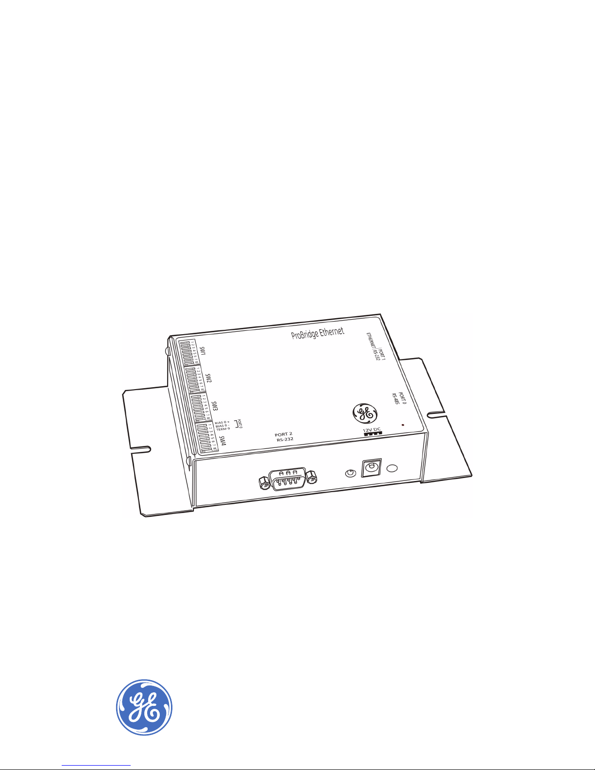
ProBridge Ethernet
User Manual
Page 2

ATM ProBridge
User Manual
ii
Copyright Copyright © 2006, GE Security Inc. All rights reserved.
This document may not be copied or otherwise reproduced, in whole or in part ,
except as specifically permitted under US and international copyright law,
without the prior written consent from GE.
Document number/ 0150-0315A (March 2006).
Disclaimer THE INFORMATION IN THIS DOCUMENT IS SUBJECT TO CHANGE WITHOUT
NOTICE. GE ASSUMES NO RESPONSIBILITY FOR INACCURACIES OR OMISSIONS
AND SPECIFICALLY DISCLAIMS ANY LIABILITIES, LOSSES, OR RISKS, PERSONAL OR
OTHERWISE, INCURRED AS A CONSEQUENCE, DIRECTLY OR INDIRECTLY, OF THE
USE OR APPLICATION OF ANY OF THE CONTENTS OF THIS DOCUMENT. FOR THE
LATEST DOCUMENTATION, CONTACT YOUR LOCAL SUPPLIER OR VISIT US ONLINE
AT WWW.GESECURITY.COM.
This publication may contain examples of screen captures and reports used in
daily operations. Examples may include fictitious names of individuals and
companies. Any similarity to names and addresses of actual businesses or
persons is entirely coincidental.
Trademarks
and patents
GE and the GE monogram are registered trademarks of General Electric.
PBe product and logo are trademarks of GE Security.
Other trade names used in this document may be trademarks or registered
trademarks of the manufacturers or vendors of the respective products.
Intended use Use this product only for the purpose it was designed for; refer to the data sheet
and user documentation. For the latest product information, contact your local
supplier or visit us online at www.gesecurity.com.
FCC
compliance
This equipment has been tested and found to comply with the limits for a
Class A digital device, pursuant to part 15 of the FCC Rules. These limits are
designed to provide reasonable protection against harmful interference when
the equipment is operated in a commercial environment. This equipment
generates, uses, and can radiate radio frequency energy and, if not installed
and used in accordance with the instruction manual, may cause harmful interference to radio communications.
You are cautioned that any changes or modifications not expressly approved by
the party responsible for compliance could void the user's authority to operate
the equipment.
Regulatory
R
Operation of this equipment in a residential area may cause interference, in which case the user is required to take all measures that
are necessary, at the user's expense, to correct the interference
Page 3

Introduction . . . . . . . . . . . . . . . . . . . . . . . . . . . . . . . . . . . . . . . . . . . . . . . . . . 1
Conventions used in this document . . . . . . . . . . . . . . . . . . . . . . . . . . . . . 2
Safety terms and symbols. . . . . . . . . . . . . . . . . . . . . . . . . . . . . . . . . . . . . . 2
Overview . . . . . . . . . . . . . . . . . . . . . . . . . . . . . . . . . . . . . . . . . . . . . . . . . . . . . 3
Compatibility . . . . . . . . . . . . . . . . . . . . . . . . . . . . . . . . . . . . . . . . . . . . . . . . . . 3
Disclaimer . . . . . . . . . . . . . . . . . . . . . . . . . . . . . . . . . . . . . . . . . . . . . . . . . . . . . 3
Product contents . . . . . . . . . . . . . . . . . . . . . . . . . . . . . . . . . . . . . . . . . . . . . . 4
Other required equipment. . . . . . . . . . . . . . . . . . . . . . . . . . . . . . . . . . . . . . 4
Installation environment . . . . . . . . . . . . . . . . . . . . . . . . . . . . . . . . . . . . . . . 5
Power specifications . . . . . . . . . . . . . . . . . . . . . . . . . . . . . . . . . . . . . . . . . . . 5
Installation . . . . . . . . . . . . . . . . . . . . . . . . . . . . . . . . . . . . . . . . . . . . . . . . . . . 7
PBe components. . . . . . . . . . . . . . . . . . . . . . . . . . . . . . . . . . . . . . . . . . . . . . . 7
Typical system layout . . . . . . . . . . . . . . . . . . . . . . . . . . . . . . . . . . . . . . . . . . 8
Installation overview . . . . . . . . . . . . . . . . . . . . . . . . . . . . . . . . . . . . . . . . . . . 9
Required information . . . . . . . . . . . . . . . . . . . . . . . . . . . . . . . . . . . . . . . . . . 9
Required DIP switch information. . . . . . . . . . . . . . . . . . . . . . . . . . . . . . . 10
Installation steps. . . . . . . . . . . . . . . . . . . . . . . . . . . . . . . . . . . . . . . . . . . . . . 10
Programming . . . . . . . . . . . . . . . . . . . . . . . . . . . . . . . . . . . . . . . . . . . . . . . . 12
HyperTerminal configuration . . . . . . . . . . . . . . . . . . . . . . . . . . . . . . . . . . 12
Manual DIP switch configuration . . . . . . . . . . . . . . . . . . . . . . . . . . . . . . 18
DIP switch settings . . . . . . . . . . . . . . . . . . . . . . . . . . . . . . . . . . . . . . . . . . . 20
SW1 switches 1 to 4. . . . . . . . . . . . . . . . . . . . . . . . . . . . . . . . . . . . . . . . . . . 20
SW1 switches 5 to 8. . . . . . . . . . . . . . . . . . . . . . . . . . . . . . . . . . . . . . . . . . . 21
SW3 switches 1 to 8. . . . . . . . . . . . . . . . . . . . . . . . . . . . . . . . . . . . . . . . . . . 22
SW4 switches 7 and 8. . . . . . . . . . . . . . . . . . . . . . . . . . . . . . . . . . . . . . . . . 22
Accessing the Webserver . . . . . . . . . . . . . . . . . . . . . . . . . . . . . . . . . . . . . 23
Troubleshooting . . . . . . . . . . . . . . . . . . . . . . . . . . . . . . . . . . . . . . . . . . . . . 25
Technical specifications . . . . . . . . . . . . . . . . . . . . . . . . . . . . . . . . . . . . . . 26
PBe . . . . . . . . . . . . . . . . . . . . . . . . . . . . . . . . . . . . . . . . . . . . . . . . . . . . . . . . . . 26
Cable Specifications. . . . . . . . . . . . . . . . . . . . . . . . . . . . . . . . . . . . . . . . . . . 27
Contacting technical support. . . . . . . . . . . . . . . . . . . . . . . . . . . . . . . . . . 30
Online publication library. . . . . . . . . . . . . . . . . . . . . . . . . . . . . . . . . . . . . . 30
Contents
Page 4

ProBridge Ethernet
User Manual
iv
Page 5

1
Introduction
This is the GE ProBridge Ethernet User Manual for model PBe.
This document includes detailed instructions explaining:
• how to setup and install the PBe ProBridge and
• how to connect to single or multiple ATM sites.
There is also information describing how to contact technical
support if you have questions. To use this document effectively,
you should meet the following minimum qualifications:
• a basic knowledge of CCTV systems and components; and
• a basic knowledge of electrical wiring and low-voltage
electrical connections.
Read these instructions and all ancillary documentation entirely
before
installing or operating this product.
Note: A qualified service person, complying with all applicable codes,
should perform whatever hardware installation is required.
Page 6
ProBridge Ethernet
User Manual
2
Conventions used in this document
The following conventions are used in this document:
Safety terms and symbols
These terms may appear in this manual:
Bold Menu items and buttons.
Italic Emphasis of an instruction or point; special terms.
File names, path names, windows, panes, tabs,
fields, variables, and other GUI elements.
Titles of books and various documents.
Blue italic (Electronic version.) Hyperlinks to cross-references,
related topics, and URL addresses.
Monospace Text that displays on the computer screen.
Programming or coding sequences.
CAUTION: Cautions identify conditions or practices that may
result in damage to the equipment or other property.
WARNING: Warnings identify conditions or practices that could
result in equipment damage or serious personal injury.
Page 7

3
Overview
The PBe is a specific ProBridge unit for interfacing the DVR
family of digital video multiplex/recorders to financial institution
automated teller machines (ATMs). The PBe supports Ethernet
network communications.
Note: The PBe operates in an NTSC environment (120 VAC/60 Hz) or a PAL
environment (220 VAC/50 Hz) provided the correct unit is ordered.
Compatibility
The PBe is compatible with all of the following DVR products:
• DVMRe, version 3.07 and above.
• DVMR-eZ, version 3.20 and above.
• Triplex, version 4.00 and above.
• Triplex-eZ, version 4.03 and above.
• WaveReader, version 3.6 and above.
Disclaimer
The PBe components identified within this document provide
means of capturing transaction data for use by the DVR family of
digital video recording/transmission products. The PBe
components translate the data into a usable format by the DVR
and permits associating transaction data with specific cameras.
GE assumes no responsibility for the amount and type of
information available, the operation, non-operation, or erroneous
operation of these third-party transaction products.
Page 8
ProBridge Ethernet
User Manual
4
Product contents
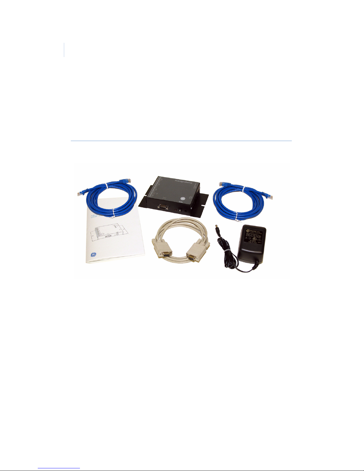
The PBe system consists of the ProBridge unit, this manual, an
Ethernet cable, a PBe to DVR cable, a PBe to PC cable, and a
power supply, as shown in Figure 1.
Figure 1. Product contents
Inspect the package and contents for visible damage. If any
components are damaged or missing, do not use the unit; contact
the supplier immediately. If you need to return the unit, you must
ship it in the original box.
Other required equipment
You might also need the following:
• A PC to program the PBe.
4310-0040
Ethernet cable
PBe
ProBridge
4310-0034B
PB3 to DVR cable
0150-0315
ProBridge Manual
4310-0061A
PBe to PC cable
Power
Supply
Page 9

5
Installation environment
Power. Ensure that the installation site’s AC power is stable
and within the rated voltage of the external power supply.
If the site’s AC power is likely to have spikes or DIPs,
use power line conditioning or an uninterruptible power
supply.
Temperature. Observe the unit’s ambient temperature
specifications when choosing a location for the unit.
Extremes of heat or cold beyond the specified operating
temperature limits may cause the unit to fail. Do not
install this unit on top of other hot equipment.
Moisture. Do not expose the unit to rain or moisture.
Moisture can damage internal components. Do not
install this unit near sources of water.
RS-232 limitations. Cable length between the POS device
and the PBe is limited to 50 ft. (15.24 m) Cable length
between the PBe unit and the DVR is also limited to 50
ft. (15.24 m). If the supplied cables are replaced by
custom made cables to address distances between
components, ensure the cable is manufactured to ANSI
standards for RS-232 communication.
Power specifications
The PBe is furnished with a power supply (110 or 240 VAC). Do
not use any other power supply with this product. The
manufacturer accepts no responsibility for damage caused by the
use of any other power supply.
Make sure installation is complete and all connections are made
before applying power to the unit.
Page 10

ProBridge Ethernet
User Manual
6
4310-0007 120 VAC power supply
Power supply input
• Voltage: 120 VAC
• Tolerance:
± 10%
• Frequency: 60 Hz
Power supply output
• Voltage: 12 VDC
• Current: 110 mA
• Power: 1.3 watts
• Connector: 2.1 mm female barrel. Center positive.
4310-0008 220VAC power supply
Power supply input
• Voltage: 220 VAC
• Tolerance:
± 10%
• Frequency: 50 Hz
Power supply output
• Voltage: 12 VDC
• Current: 110 mA
• Power: 1.3 watts
• Connector: 2.1 mm female barrel. Center positive.
Page 11
7
Installation
Before installation, please familiarize yourself with the PBe and
its typical system layout.
PBe components
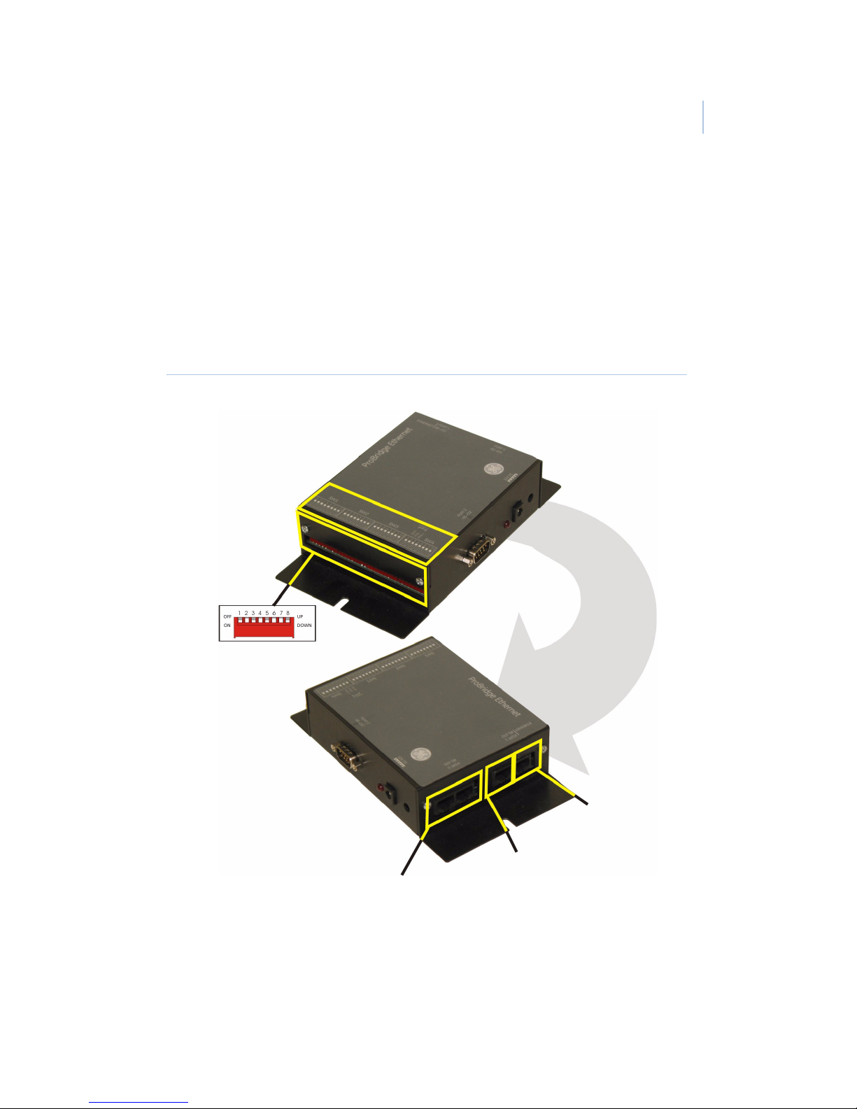
Figure 2. PBe landmarks
Power connection
Port 2/RS-232
Connects to the PC
Port 0/RS-485
Connects multiple PBes together
Port 1/RS-232
Ethernet Port
Page 12
ProBridge Ethernet
User Manual
8
Typical system layout
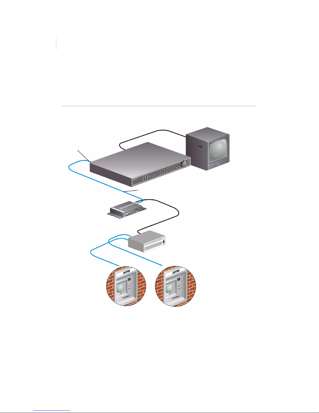
The following figure shows a typical multiple ATM layout.
Figure 3. Multiple ATM system layout
RS232 port
4310-0034B
RJ45 to RJ45 cable
Existing ATMs
4310-0040
Ethernet cable
PBe
Ethernet
Hub
Page 13

9
Installation overview
The basic steps required to install the PBe are:
1. Physically connect the PBe interface to the network
switch or hub and the DVR using the supplied cables.
2. Program monitor mode to on by setting SW1 switches 1
to 4. See SW1 switches 1 to 4 on page 20 for the switch
settings.
3. Program the camera number to be associated with the
ATM’s transaction data to the PBe. See SW1 switches 5
to 8 on page 21.
4. Program the DVR to record in the way desired for your
specific site.
Required information
The following information is required for a successful PBe
installation. This information is used to configure the PBe. You
will need to contact the customer’s ATM network administrator
for answers to these questions.
Ethernet device type
• Generic interface
• Native ATM messages (FC)
• Verifone POS
• Ethernet data analyzer
Page 14

ProBridge Ethernet
User Manual
10
Required DIP switch information
Important switch assignments
Table 1. Important switch assignments
Default switch settings
Installation steps
1. Select the camera number (1-16) on the DVR on which to
associate the ATM transaction text. This is done by
SW1 1-4 Special functions
SW1 5-8 Camera assignment
SW3 1-8 Device type
Table 2. Default switch settings
SW1 SW2 SW3 SW4
1Up1Up1Up1Up
2Up2Up2Up2Up
3Up3Up3Up3Up
4Up4Up4Up4Up
5Up5Up5Up5Up
6Up6Up6Up6Up
7Up7Up7Up7Down
8Up8Up8Up8Up
Page 15

11
setting switches 5-8 on SW1. See SW1 switches 5 to 8 on
page 21.
2. Connect the PBe to the network switch or hub using the
supplied 4310-0040 Ethernet cable.
3. Connect the PBe to the DVR using the supplied 43100034 cable. Plug one end into port 1 of the PBe and the
other end into the RS-232/2 port of the DVR.
4. Program the DVR for the desired recording functions
based upon the presence of transaction text. In addition,
make sure the RS-232/2 port is set for a 57600 baud rate.
See the DVR manual for more information.
5. Apply power to the PBe using the supplied power supply.
Page 16

ProBridge Ethernet
User Manual
12
Programming
After you install the PBe, you need to program the ProBridge for
operation. This is accomplished by using HyperTerminal or
manually setting the DIP switches.
HyperTerminal configuration
You will need the following equipment to program the PBe using
HyperTerminal:
• A PC or laptop computer with a COM port and Windows
98/NT/200/XP installed and operational.
• The supplied 4310-0061A PB3 to PC (DB9F to DB9F)
cable.
To program the PBe with HyperTerminal, do the following:
1. Remove power and disconnect the PBe from the DVR.
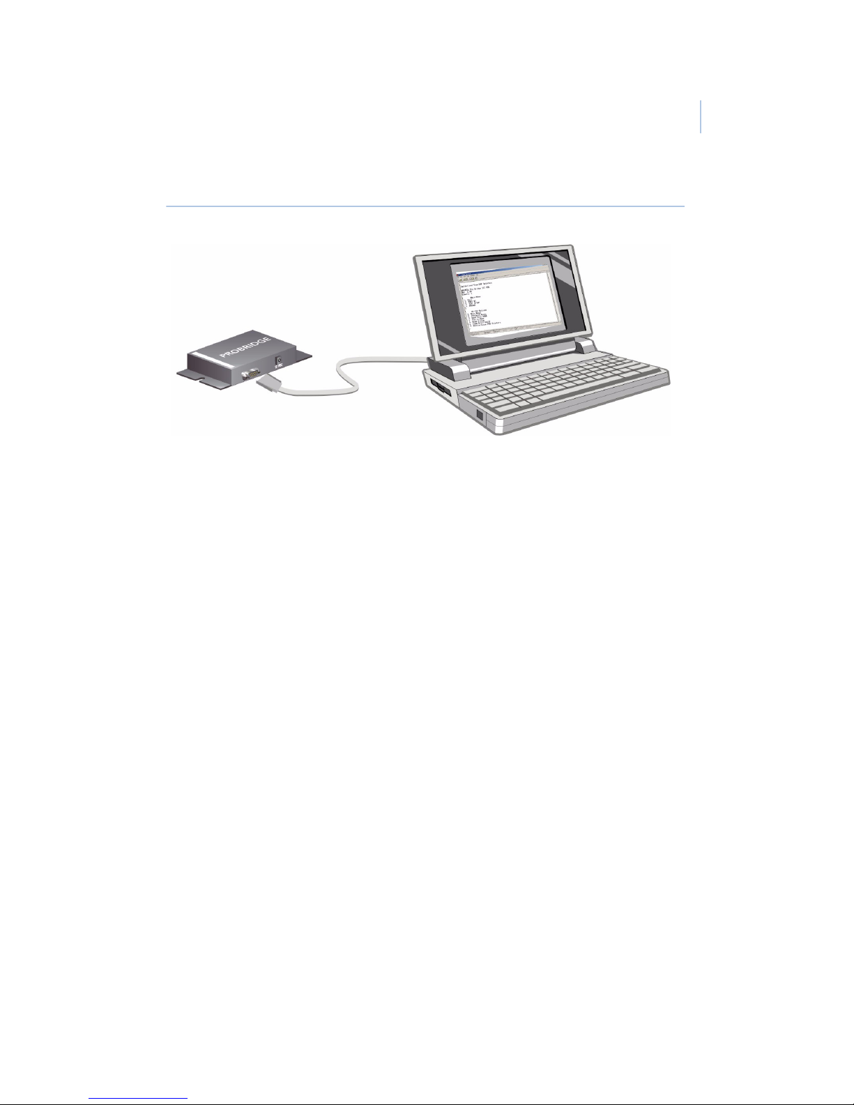
2. Plug the 4310-0061A cable into Port 2 of the PBe and a
free COM port on your PC, typically COM1.
3. Launch HyperTerminal, found in
Start\Programs\Accessories\Communications\
HyperTerminal.
Page 17
13
Figure 4. Laptop connected to PBe
4. The Connection Description dialog box will display.
Type in a name for this session (PBe) and click OK.
5. The Connect To dialog box display. Select the COM port
you are connected to in the Connect Using drop-down
list.
6. The COMx Properties dialog box will display. Select the
following settings to complete the HyperTerminal setup:
• Bits per second = 57600
• Data bits = 8
• Parity = none
• Stop bits = 1
• Flow control = none
7. Click OK.
To program the PBe do the following:
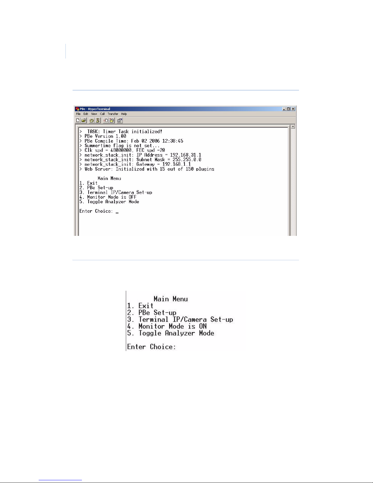
1. Power up the PBe by plugging in the power supply. The
window shown in Figure 5 will appear confirming that
you are in HyperTerminal programming mode.
Page 18
ProBridge Ethernet
User Manual
14
Figure 5. HyperTerminal programming mode
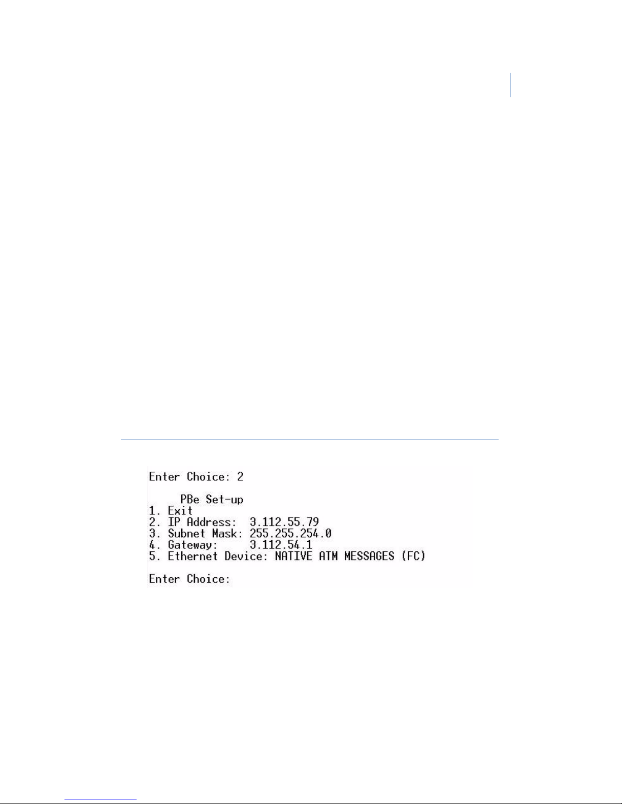
2. Press the Enter key twice to bring up the Main Menu.
Figure 6. Main menu
Page 19
15
Main Menu
There are five menu selections on the Main Menu:
• Exit - Exits the maim menu and saves any changes.
• PBe Set-up - provides IP address setup and Ethernet
device selection.
• Terminal IP/Camera Set-up - Enables or disables the IP
camera and provides addressing options.
• Monitor Mode - Toggles Ethernet monitoring On or Off.
• Toggle Analyzer Mode - Used for Technical support
only.
PBe Set-up menu
Selecting option #2 from the main menu launches the PBe Set-up
menu.
Figure 7. The PBe Set-up menu
We recommend that you do not change the IP addresses from the
defaults shown in Figure 7. The Ethernet Device option is the
only option in this menu that you should change. To change the
Ethernet device press 5 and then the enter key. The next device on
Page 20

ProBridge Ethernet
User Manual
16
the list will be selected. The PBe supports the following Ethernet
devices:
• Generic interface
• Native ATM messages (FC)
• Verifone POS
• Ethernet data analyzer
Note: The Ethernet device can also be selected by DIP switch. See SW3
switches 1 to 8 on page 22.
Terminal IP/Camera Set-up menu
Selecting option #3 from the main menu launches the Terminal
IP/Camera Set-up menu.
Figure 8. The terminal IP/camera set-up menu
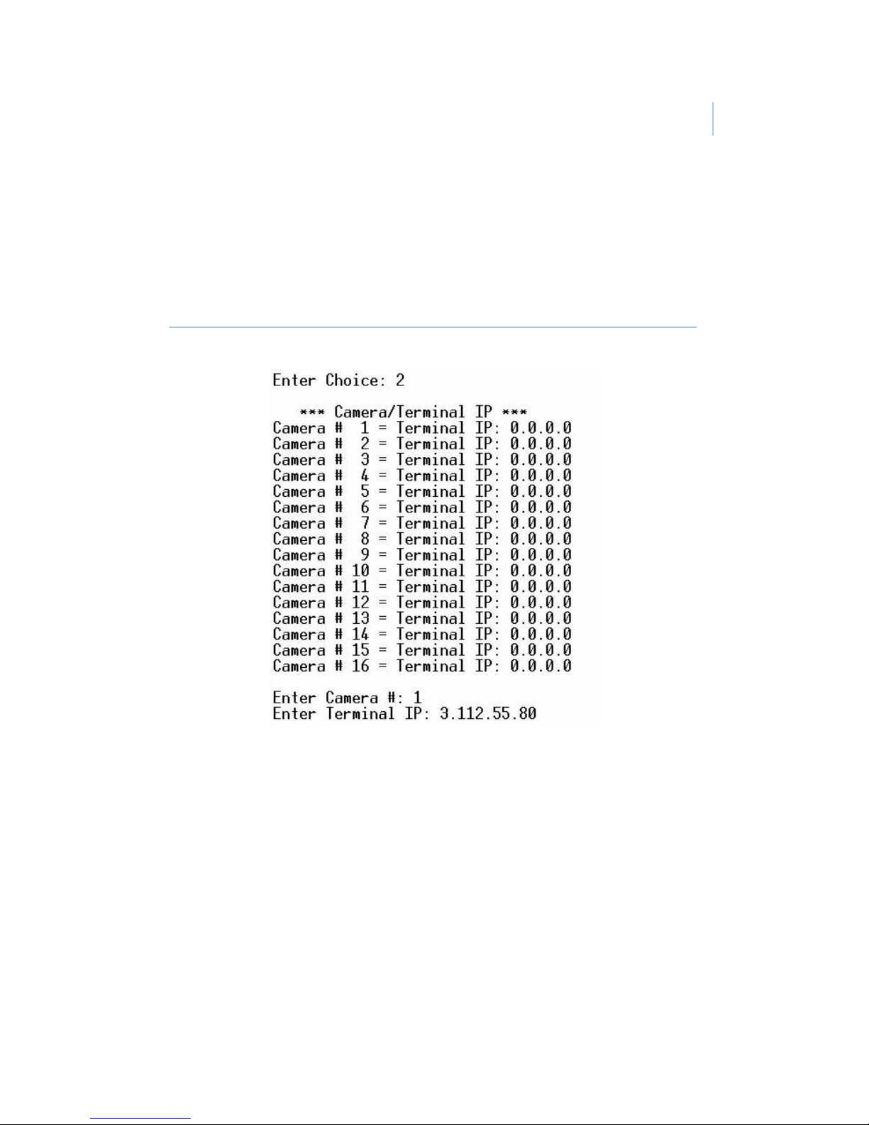
Option #2 lets you associate cameras to terminals by the camera
number and the terminals IP address. To associate a camera to a
specific terminal do the following:
1. Press #2 and the enter key to display the camera/terminal
list.
2. Enter the camera number that you want and the enter key.
3. Type in the IP address of the terminal to associate to the
camera and press the enter key.
Page 21
17
4. The camera/terminal will redisplay with the new
information.
5. Pressing the enter key will terminate the camera/terminal
IP set-up and return you to the previous menu.
Figure 9. The camera/terminal IP table
Option #3 lets you enable/disable the Use IP for Camera
command. When set to Enabled the PBe will search the
incoming UDP and TCP packets for a match of IP addresses.
Depending on the Device setting the PBe will parse the data
received in that packet and send it to the associated camera
number.
The Monitor Mode menu
The fourth selection on the Main Menu is the Monitor Mode on/
off toggle. This selection will toggle between off and on when 4
Page 22

ProBridge Ethernet
User Manual
18
ins entered followed by the enter key. Changing the selection to
on allows the PBe to monitor the incoming Ethernet packets.
Note: Monitor mode should be turned off before upgrading the PBe.
In some cases whenever SW3 is used to select the Ethernet
Device, monitor mode will automatically be turned on.
Analyzer Mode menu
This menu is used for troubleshooting only. Do not use unless
requested by a qualified technician.
Exiting HyperTerminal
To exit HyperTerminal do the following:
1. Enter the number 1 and the enter key until the message
“Exiting menus Ready!” is displayed.
2. Close the HyperTerminal screen. You do not need to save
the session for your changes to take effect.
1. Remove the RS-232 cable and reconnect the PBe to the
DVR.
Manual DIP switch configuration
The Ethernet Device and Camera Selection can also be selected
manually by changing the DIP switch setting see DIP switch
settings on page 20. Follow the steps below to change the DIP
switches:
1. Disconnect power from the PBe
2. Disconnect the PBe from the DVR.
Page 23

19
3. Set the DIP switches per the tables in DIP switch settings
on page 20 to match the changes desired.
4. Reconnect the PBe to the DVR.
5. Reapply power to the PBe.
Page 24
ProBridge Ethernet
User Manual
20
DIP switch settings
This chapter deals in detail with the DIP switch settings. The PBe
must be re initialized before any changes to the switch settings
will be recognized.
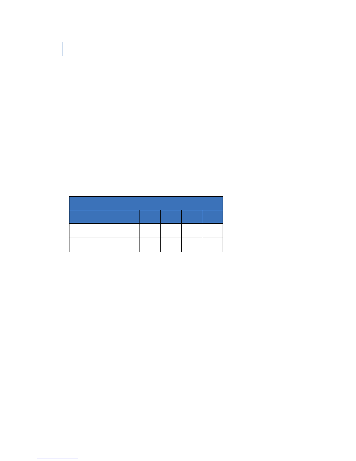
SW1 switches 1 to 4
Switches 1 to 4 on SW1 are for turning monitor mode on or off.
Table 3. SW1 switches 1 to 4 - monitor mode
SW1
Function 1 2 3 4
Monitor OFF UUUU
Monitor ON DUUU
Page 25

21
SW1 switches 5 to 8
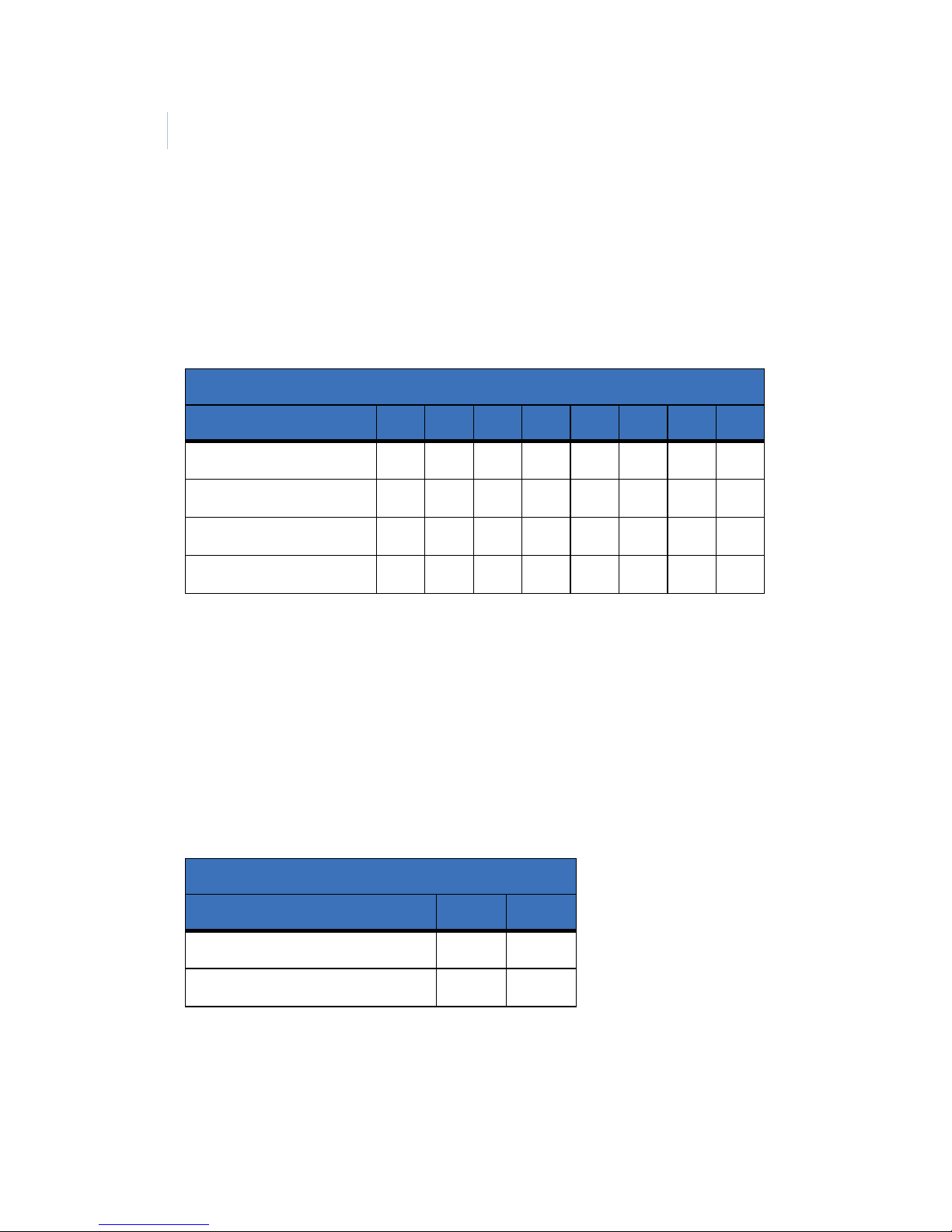
Switches 5 to 8 on SW1 are for associating a specific camera on
the DVR to the PBe.
Table 4. SW1 switches 5 to 8 - Camera number selection
SW1
Camera number 5 6 7 8
1 UUUU
2 UUUD
3 UUDU
4 UUDD
5UDUU
6UDUD
7 UDDU
8UDDD
9 DUUU
10 D U U D
11 DUDU
12 D U D D
13 DDUU
14 DDUD
15 DDDU
16 DDDD
Page 26
ProBridge Ethernet
User Manual
22
SW3 switches 1 to 8
The switch positions on SW3 are for selecting the Ethernet device
type.
These switches are reserved for technical support. Do not use.
SW4 switches 7 and 8
Switches 7 and 8 on switch 4 control the communication protocol
between the PBe at port 1 and the DVR or PC. Normally this is
set at RS-232.
Table 5. SW3 switches 1 to 8 - Device type
SW3
Switch function 1 2 3 4 5 6 7 8
Ethernet Analyzer UUUUUUUU
Generic UUUUUUUD
Native ATM UUUUUUDU
Verifone POS UUUUUUDD
Table 6. SW4 switches 7 and 8 - communication protocol
SW4
Communication protocol 7 8
RS-232 D U
RS-485 U D
Page 27

23
Accessing the Webserver
The PBe has a built-in webpage for simple configuration changes
and remote upgrade. To access the webpage do the following:
1. Obtain the IP addresses for the PBe. The default address
are:
• IP Address: 3.112.55.79
• Subnet mask: 255.255.254.0
• Gateway address: 3.112.54.1
2. Connect an Ethernet cable from the Ethernet port on the
PBe to a PC or hub.
3. Launch a WebBroswer program like Microsoft Explorer.
4. Enter the IP address of the PBe in the address bar of the
browser.
5. The Enter Password dialog box will appear. The default
log in and password for the PBe are:
•admin
•admin
6. Click the OK button and the Webpage will display.
Page 28
ProBridge Ethernet
User Manual
24
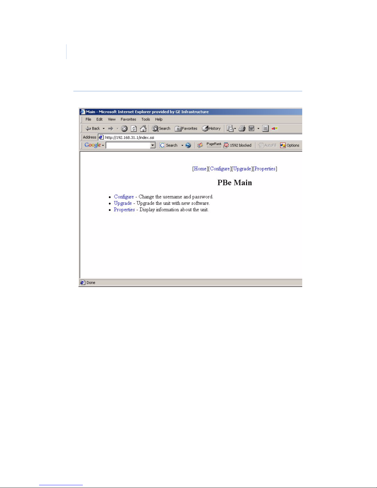
Figure 10. The PBe home page
Click on any of the hyperlinked text to navigate to that feature’s
page.
Page 29

25
Troubleshooting
Use the table below to solve some of the most common problems
Table 7. Troubleshooting table
Problem Probable cause Solution
No red LEd Fuse is bad
No Power
Replace fuse
Check Power Supply
No text on DVR text
box
DVR baud rate
incorrect
Cable not connected
on PBe port #1
Change DVR baud rate
to 57600
Check cable
connections
Not capturing data
from switch
SPAN port not
configured to echo
data
Consult your IS group
leader for this network
Page 30

ProBridge Ethernet
User Manual
26
Technical specifications
PBe
General
Environmental
Electrical
Housing: Metal enclosure
Dimensions: 4 x 7 x 1.5 in. (100 x 175 x 38 mm)
Weight: 5.2 oz. (161 g)
Color: Black
Operating temperature: 0 to 40º C.
Relative humidity: 10 to 80%. Storage: 10 to 95%
AC power: Included external power supply
Voltage range:
110 to 240 VAC
±10%
Current: 200 mA
DC power: DC jack, positive center
Power supply voltage: 12 VDC
Current: 110 mA
Power consumption: 1.5 watts max.
Page 31
27
Cable Specifications
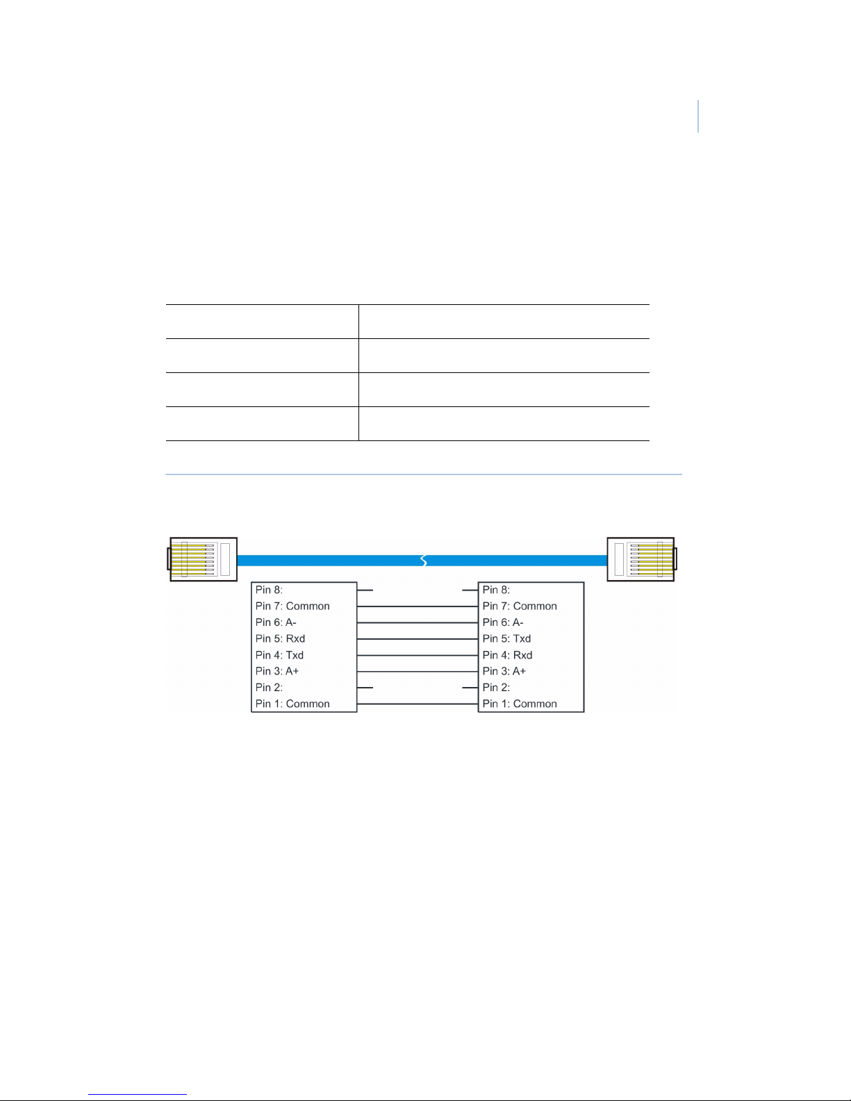
PBe to DVR
Figure 11. 4310-0034B cable
Part number: 4310-0034B
Communication type: RS-232
Connector type: RJ45
Length: 5 ft. (1.52 m)
Pin 1
Pin 1
Page 32
ProBridge Ethernet
User Manual
28
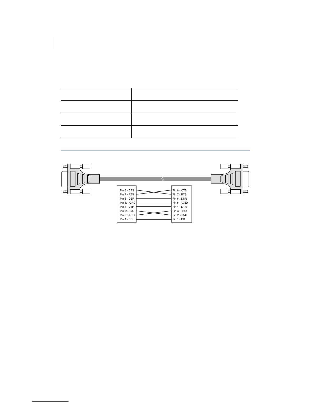
PBe to PC
Figure 12. 4310-0061 cable
Part number: 4310-00061
Communication type: RS-232/Null Modem
Connector type: DB9-F, DB9-F
Length: 6 ft. (1.82 m)
Page 33
29
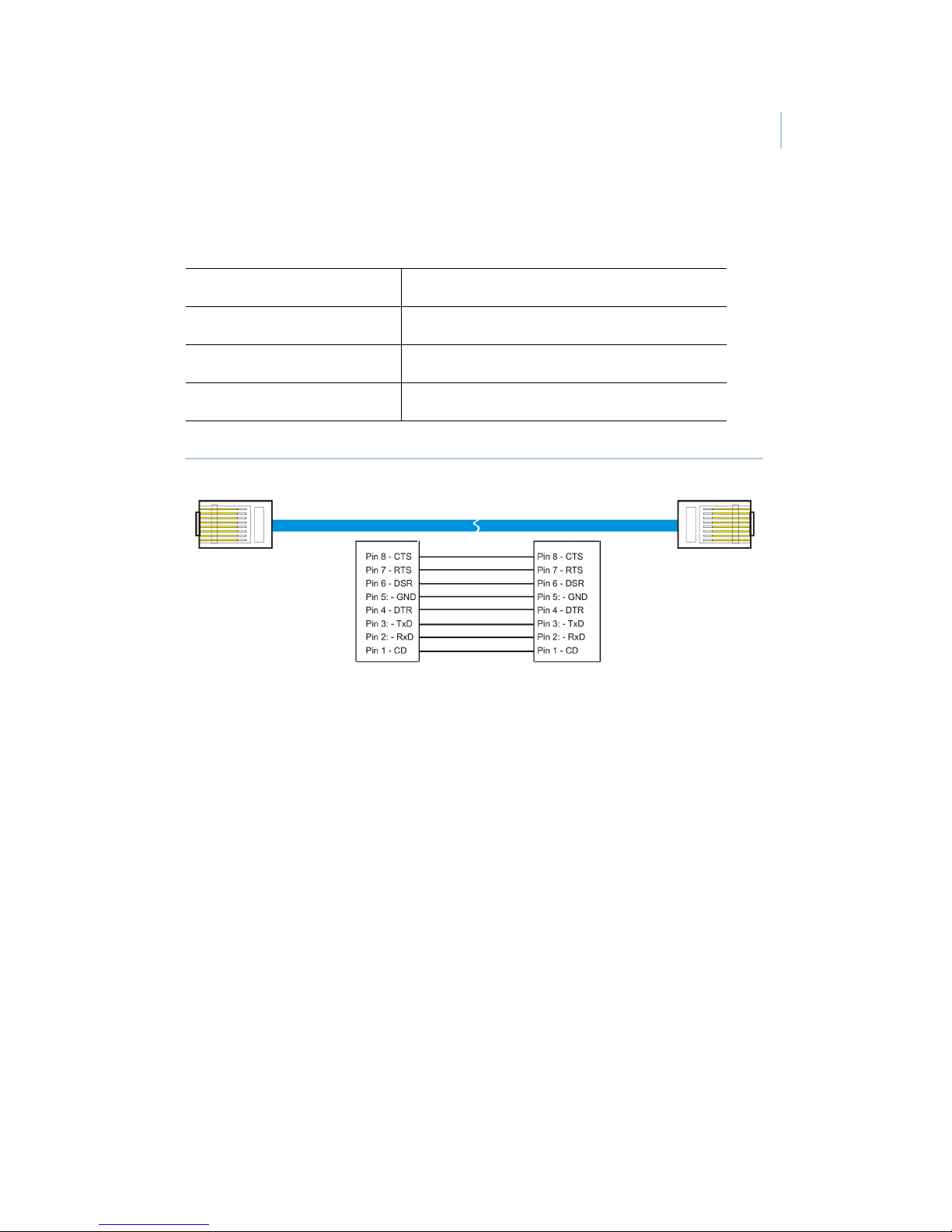
PBe Ethernet cable
Figure 13. 4310-0040 PBe Ethernet
Part number: 4310-0040
Communication type: Ethernet
Connector type: RJ45, RJ45
length: 6 ft. (1.83 m)
Page 34
ProBridge Ethernet
User Manual
30
Contacting technical support
For assistance installing, operating, maintaining, and
troubleshooting this product, refer to this document and any other
documentation provided. If you still have questions, you may
contact technical support during normal business hours (Monday
through Friday, excluding holidays, between 6 a.m. and 5 p.m.
Pacific Time).
Note: Be ready at the equipment before calling for technical support.
Online publication library
Another great resource for assistance with your GE product is our
online publication library, available to all of our customers. To
access the library, go to our website at the following location:
http://www.gesecurity.com
In the Too ls area at the top, click the Publication Library link.
After you register and log on, you may search through our online
library for the documentation you need.
1
Table 8. Sales and support contact information
Sales Technical support
Phone
Toll-free: 888.GESECURity (888.437.3287 in the US, including
Alaska and Hawaii; Puerto Rico; Canada).
Outside the toll-free area: 503.885.5700.
E-mail
Fax
800.483.2495 541.752.9096 (24 hours/day)
1. Many GE documents are provided as PDFs. To read these documents,
you will need Adobe Acrobat Reader, which can be downloaded free
from Adobe’s website at www.adobe.com.
 Loading...