

GE ProBridge, ProBridge CBR-PB3-GW User Manual
ProBridge Gateway
User Manual

Copyright Copyright © 2006, GE Security Inc. All rights reserved.
This document may not be copied or otherwise reproduced, in whole or in part ,
except as specifically permitted under US and international copyright law,
without the prior written consent from GE.
Document number/revision: 0150-0265C (April 2006).
Disclaimer THE INFORMATION IN THIS DOCUMENT IS SUBJECT TO CHANGE WITHOUT
NOTICE. GE ASSUMES NO RESPONSIBILITY FOR INACCURACIES OR OMISSIONS
AND SPECIFICALLY DISCLAIMS ANY LIABILITIES, LOSSES, OR RISKS, PERSONAL OR
OTHERWISE, INCURRED AS A CONSEQUENCE, DIRECTLY OR INDIRECTLY, OF THE
USE OR APPLICATION OF ANY OF THE CONTENTS OF THIS DOCUMENT. FOR THE
LATEST DOCUMENTATION, CONTACT YOUR LOCAL SUPPLIER OR VISIT US ONLINE
AT WWW.GESECURITY.COM.
This publication may contain examples of screen captures and reports used in
daily operations. Examples may include fictitious names of individuals and
companies. Any similarity to names and addresses of actual businesses or
persons is entirely coincidental.
Trademarks
and patents
GE and the GE monogram are registered trademarks of General Electric.
Other trade names used in this document may be trademarks or registered
trademarks of the manufacturers or vendors of the respective products.
Intended use Use this product only for the purpose it was designed for; refer to the data sheet
and user documentation. For the latest product information, contact your local
supplier or visit us online at www.gesecurity.com.
FCC
compliance
This equipment has been tested and found to comply with the limits for a
Class A digital device, pursuant to part 15 of the FCC Rules. These limits are
designed to provide reasonable protection against harmful interference when
the equipment is operated in a commercial environment. This equipment
generates, uses, and can radiate radio frequency energy and, if not installed
and used in accordance with the instruction manual, may cause harmful interference to radio communications.
You are cautioned that any changes or modifications not expressly approved by
the party responsible for compliance could void the user's authority to operate
the equipment.
Regulatory

ProBridge Gateway Table of Contents
0150-0265C / April 2006 3
TABLE OF CONTENTS
PREFACE................................................................................4
1 OVERVIEW........................................................................5
1.1 PROBRIDGE GATEWAY COMPONENTS:........................5
1.1.1 Installation Environment...............................................6
1.2 POWER.....................................................................6
1.3 PROBRIDGE GATEWAY PRODUCT DIAGRAM.................7
1.3.1 Dipswitch Position Legend...........................................8
2 PROGRAMMING MODE .......................................................8
3 OPERATING MODE.............................................................9
4 OPERATION ....................................................................10
4.1 ADDRESSING:..........................................................10
4.2 PRESETS:...............................................................10
5 CABLE SPECIFICATIONS...................................................10
5.1 PROBRIDGE TO DVMRE TRIPLEX CABLE ..................10
5.2 PROBRIDGE TO PC CABLE.......................................11
5.3 PROBRIDGE TO I/O JUNCTION BOX OR CYBERDOMES11
6 SPECIFICATIONS..............................................................12

GE Security ProBridge Gateway
4 0150-0265C / April 2006
PREFACE
This document includes an overview of the product and detailed
instructions explaining how to install and operate the unit. There is also
information describing how to contact technical support if you have
questions or concerns.
To use this document effectively, you should have the following minimum
qualifications:
• a basic knowledge of CCTV systems and components; and
• a basic knowledge of electrical wiring and low-voltage electrical
hookups.
Read these instructions and all ancillary documentation entirely before
installing or operating this product. The most current versions of this and
related documentation may be found on our website.
Note: A qualified service person, complying with all applicable codes, should perform all
required hardware installation.
These terms may appear in this manual:
* WARNING:
Improper use of this equipment can cause severe bodily injury or
equipment damage.
** CAUTION:
Improper use of this equipment can cause equipment damage.
Note: Notes contain important information about a product or procedure.
* This symbol indicates electrical warnings and cautions.
** This symbol indicates general warnings and cautions.

ProBridge Gateway GE Security
0150-0265C / April 2006 5
1 OVERVIEW
The ProBridge Gateway is a product specific Protocol translator that converts
RS485 messages of the DVMRe products to the RS422 messages needed for
the CyberDome. This allows systems to utilize PTZ control over the TCP/IP
connection with WaveReader in systems that use camera addressing based on
matrix switcher input numbers.
The ProBridge Gateway has the following two modes of op eratio n:
• The Programming mode
• The Operating mode
In the Programming mode the installer can set up the mapping between camera
inputs of the DVMRe products and CyberDomes. This allows for totally arbitrary
camera mapping, i.e. DVMRe 5, camera input 14 can be mapped to dome
address number 983.
In the Operating mode the ProBridge Gateway will translate messages to ensure
that telemetry messages originating from DVMRe products will correctly address
the intended dome.
1.1 PROBRIDGE GATEWAY COMPONENTS:
The ProBridge Gateway product includes:
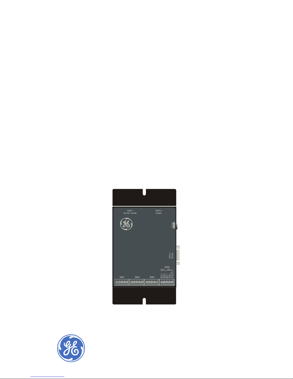
(1) CBR-PB3-GW ProBridge unit.
(1) P/N 4310-0034B: RJ45 to RJ45 cable. Connects the ProBridge Gateway
RS485 Port 0 to the DVMRe Triplex RS485 port. This cable is 6’ in length .
(1) P/N 4310-0047B: RJ45 to DB9F cable. Connects the ProBridge Gateway to
RS232 Port 1 to a PC for programming. This cable is 6’ in length.
(1) P/N 4310-0032A: RJ45 to flying leads cable. Connects the ProBridge
Gateway to the KTD-405 Keyboard I/O box or to the CyberDomes via a KTD-83
data distribution module. This cable is 6’ in length.
(1) P/N 4010-0007: 12VDC 120VAC Power Supply or P/N 4010-0008: 12VDC
220VAC Power Supply.
(1) P/N 0150-0265A: ProBridge Gateway User Manual.
 Loading...