

Page 1

ProBridge Gateway
User Manual
Page 2

Copyright Copyright © 2006, GE Security Inc. All rights reserved.
This document may not be copied or otherwise reproduced, in whole or in part ,
except as specifically permitted under US and international copyright law,
without the prior written consent from GE.
Document number/revision: 0150-0265C (April 2006).
Disclaimer THE INFORMATION IN THIS DOCUMENT IS SUBJECT TO CHANGE WITHOUT
NOTICE. GE ASSUMES NO RESPONSIBILITY FOR INACCURACIES OR OMISSIONS
AND SPECIFICALLY DISCLAIMS ANY LIABILITIES, LOSSES, OR RISKS, PERSONAL OR
OTHERWISE, INCURRED AS A CONSEQUENCE, DIRECTLY OR INDIRECTLY, OF THE
USE OR APPLICATION OF ANY OF THE CONTENTS OF THIS DOCUMENT. FOR THE
LATEST DOCUMENTATION, CONTACT YOUR LOCAL SUPPLIER OR VISIT US ONLINE
AT WWW.GESECURITY.COM.
This publication may contain examples of screen captures and reports used in
daily operations. Examples may include fictitious names of individuals and
companies. Any similarity to names and addresses of actual businesses or
persons is entirely coincidental.
Trademarks
and patents
GE and the GE monogram are registered trademarks of General Electric.
Other trade names used in this document may be trademarks or registered
trademarks of the manufacturers or vendors of the respective products.
Intended use Use this product only for the purpose it was designed for; refer to the data sheet
and user documentation. For the latest product information, contact your local
supplier or visit us online at www.gesecurity.com.
FCC
compliance
This equipment has been tested and found to comply with the limits for a
Class A digital device, pursuant to part 15 of the FCC Rules. These limits are
designed to provide reasonable protection against harmful interference when
the equipment is operated in a commercial environment. This equipment
generates, uses, and can radiate radio frequency energy and, if not installed
and used in accordance with the instruction manual, may cause harmful interference to radio communications.
You are cautioned that any changes or modifications not expressly approved by
the party responsible for compliance could void the user's authority to operate
the equipment.
Regulatory
Page 3

ProBridge Gateway Table of Contents
0150-0265C / April 2006 3
TABLE OF CONTENTS
PREFACE................................................................................4
1 OVERVIEW........................................................................5
1.1 PROBRIDGE GATEWAY COMPONENTS:........................5
1.1.1 Installation Environment...............................................6
1.2 POWER.....................................................................6
1.3 PROBRIDGE GATEWAY PRODUCT DIAGRAM.................7
1.3.1 Dipswitch Position Legend...........................................8
2 PROGRAMMING MODE .......................................................8
3 OPERATING MODE.............................................................9
4 OPERATION ....................................................................10
4.1 ADDRESSING:..........................................................10
4.2 PRESETS:...............................................................10
5 CABLE SPECIFICATIONS...................................................10
5.1 PROBRIDGE TO DVMRE TRIPLEX CABLE ..................10
5.2 PROBRIDGE TO PC CABLE.......................................11
5.3 PROBRIDGE TO I/O JUNCTION BOX OR CYBERDOMES11
6 SPECIFICATIONS..............................................................12
Page 4
GE Security ProBridge Gateway
4 0150-0265C / April 2006
PREFACE
This document includes an overview of the product and detailed
instructions explaining how to install and operate the unit. There is also
information describing how to contact technical support if you have
questions or concerns.
To use this document effectively, you should have the following minimum
qualifications:
• a basic knowledge of CCTV systems and components; and
• a basic knowledge of electrical wiring and low-voltage electrical
hookups.
Read these instructions and all ancillary documentation entirely before
installing or operating this product. The most current versions of this and
related documentation may be found on our website.
Note: A qualified service person, complying with all applicable codes, should perform all
required hardware installation.
These terms may appear in this manual:
* WARNING:
Improper use of this equipment can cause severe bodily injury or
equipment damage.
** CAUTION:
Improper use of this equipment can cause equipment damage.
Note: Notes contain important information about a product or procedure.
* This symbol indicates electrical warnings and cautions.
** This symbol indicates general warnings and cautions.
Page 5

ProBridge Gateway GE Security
0150-0265C / April 2006 5
1 OVERVIEW
The ProBridge Gateway is a product specific Protocol translator that converts
RS485 messages of the DVMRe products to the RS422 messages needed for
the CyberDome. This allows systems to utilize PTZ control over the TCP/IP
connection with WaveReader in systems that use camera addressing based on
matrix switcher input numbers.
The ProBridge Gateway has the following two modes of op eratio n:
• The Programming mode
• The Operating mode
In the Programming mode the installer can set up the mapping between camera
inputs of the DVMRe products and CyberDomes. This allows for totally arbitrary
camera mapping, i.e. DVMRe 5, camera input 14 can be mapped to dome
address number 983.
In the Operating mode the ProBridge Gateway will translate messages to ensure
that telemetry messages originating from DVMRe products will correctly address
the intended dome.
1.1 PROBRIDGE GATEWAY COMPONENTS:
The ProBridge Gateway product includes:
(1) CBR-PB3-GW ProBridge unit.
(1) P/N 4310-0034B: RJ45 to RJ45 cable. Connects the ProBridge Gateway
RS485 Port 0 to the DVMRe Triplex RS485 port. This cable is 6’ in length .
(1) P/N 4310-0047B: RJ45 to DB9F cable. Connects the ProBridge Gateway to
RS232 Port 1 to a PC for programming. This cable is 6’ in length.
(1) P/N 4310-0032A: RJ45 to flying leads cable. Connects the ProBridge
Gateway to the KTD-405 Keyboard I/O box or to the CyberDomes via a KTD-83
data distribution module. This cable is 6’ in length.
(1) P/N 4010-0007: 12VDC 120VAC Power Supply or P/N 4010-0008: 12VDC
220VAC Power Supply.
(1) P/N 0150-0265A: ProBridge Gateway User Manual.
Page 6
GE Security ProBridge Gateway
6 0150-0265C / April 2006
1.1.1 INSTALLATION ENVIRONMENT
Power: Ensure that the installation site’s AC power is stable and within the rated
voltage of the external power supply. If the site’s AC power is likely to have
spikes or dips, use power line conditioning or an Uninterruptible Power Supply.
Temperature: Observe the unit’s ambient temperature specifications when
choosing a location for the unit. Extremes of heat or cold beyond the specified
operating temperature limits may cause the unit to fail. Do not install this unit on
top of other hot equipment.
Moisture: Do not expose the unit to rain or moisture. Moisture can damage
internal components. Do not install this unit near sources of water.
RS-232 Limitations: Cable length between the PC and ProBridge is limited to
50’. If the supplied cable is replaced by custom made cables to address
distances between components, ensure the cable is manufactured to ANSI
standards for RS-232 communication.
RS485 Limitations: If multiple RS485 devices are connected together, the
distance between the first and last device is limited to 3,000 feet (RS-485
communications).
1.2 POWER
The ProBridge is furnished with a power supply (110 or 240 VAC). Do not use
any other power supply with this product. The manufacturer accepts no
responsibility for damage caused by the use of any other power sup ply.
Make sure installation is complete and all connections are made before applying
power to the unit.
4310-0007: 120VAC Power Supply
Power Supply Input
Voltage: 120 Volt AC
Tolerance: ±10%
Frequency: 60 Hz
Power Supply Output
Voltage: 12 Volt DC
Current: 110mA
Power: 1.3 Watts
Connector: 2.1mm female barrel. Center Positive
Page 7
ProBridge Gateway GE Security
0150-0265C / April 2006 7
4310-0008: 220VAC Power Supply
Power Supply Input
Voltage: 220 Volt AC
Tolerance: ±10%
Frequency: 50 Hz
Power Supply Output
Voltage: 12 Volt DC
Current: 110mA
Power: 1.3 Watts
Connector: 2.1mm female barrel. Center Positive
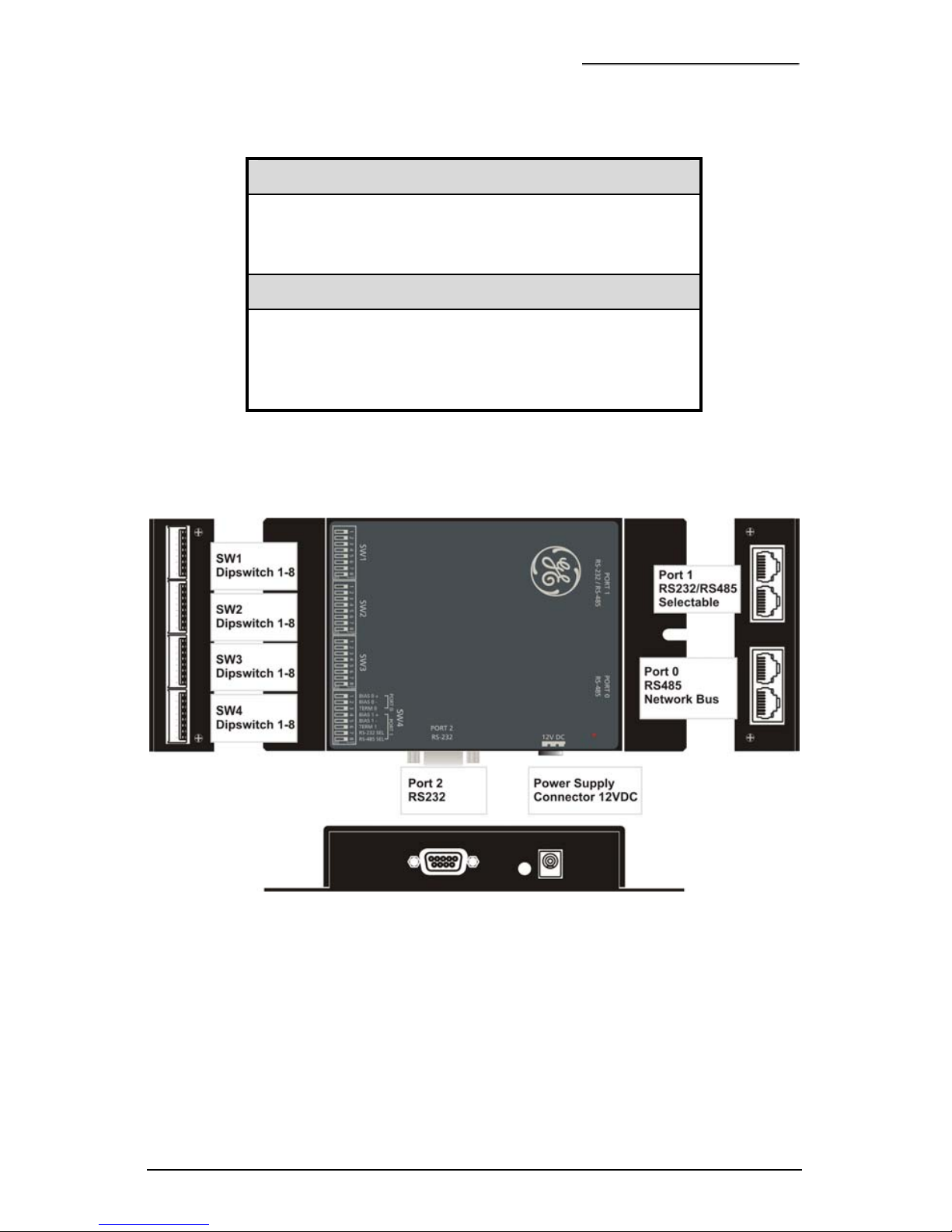
1.3 PROBRIDGE GATEWAY PRODUCT DIAGRAM
Note: Port 0 and Port 1 have looping RJ45 connectors.
Page 8
GE Security ProBridge Gateway
8 0150-0265C / April 2006
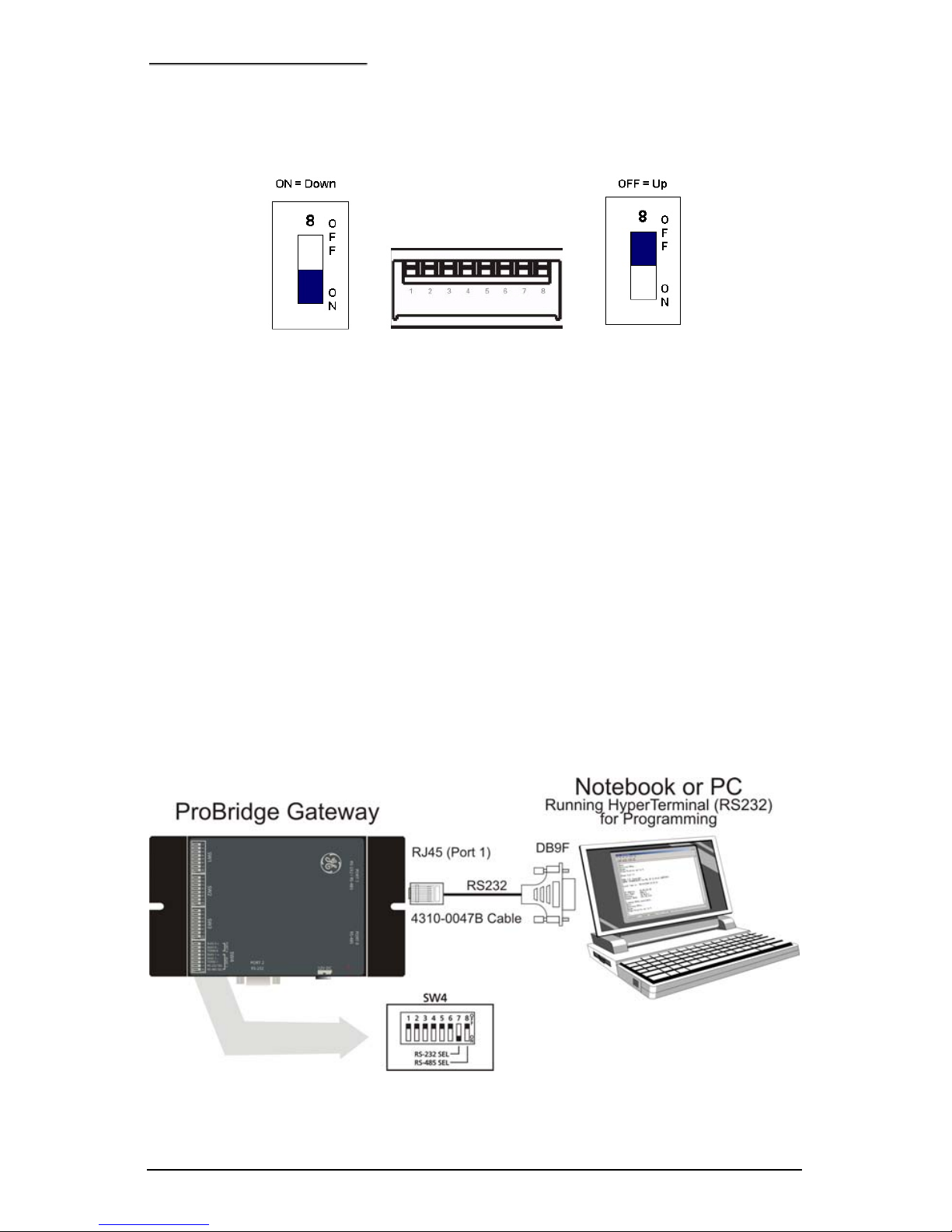
1.3.1 DIPSWITCH POSITION LEGEND
2 PROGRAMMING MODE
Setting the ProBridge Gateway to Programming mode:
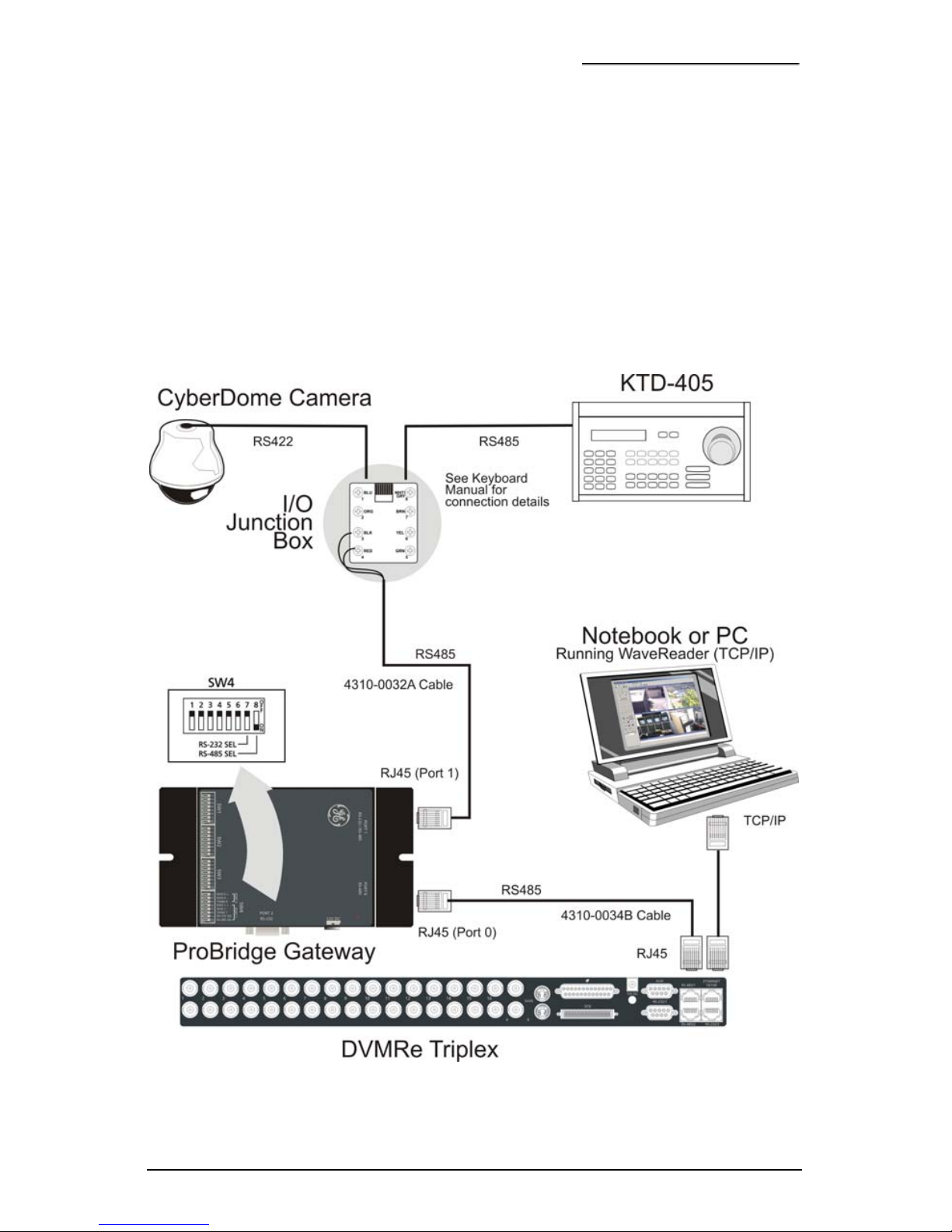
• Set the device to programming mode by setting the dipswitch at SW4.
(SW4-7 RS232 SEL on, SW4-8 RS485 SEL off)
• Ensure the RS232 (4310-0047B) cable is connected from the PC to one
of the port 1 connectors on the ProBridge Gateway.
• Open HyperTerminal on a PC,
o Set the RS232 port to 9600, N, 8, 1 and flow control to None.
(File/Properties, “Connect to” tab, “Configure” button)
o Set local echo on (File/Properties, “Settings” tab, “ASCII Setup”
button)
• Cycle power on the ProBridge Gateway box and follow the instructions
in HyperTerminal.
Connection Diagram for programming mode is shown below
Page 9
ProBridge Gateway GE Security
0150-0265C / April 2006 9
3 OPERATING MODE
Setting the ProBridge Gateway in Operating mode:
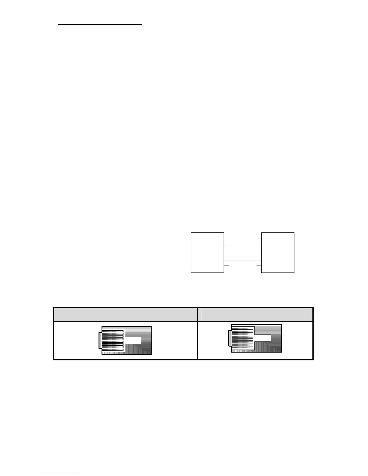
• Set the device to operating mode by setting the dipswitch at SW4.
(SW4-7 RS232 SEL off, SW4-8 RS485 SEL on)
• Connect the devices and cables as shown below.
• Cycle power on the ProBridge Gateway box and the other devices.
Connection Diagram for Operating mode is shown below.
KB3 Protocol menu item must be set to YES.
Page 10
GE Security ProBridge Gateway
10 0150-0265C / April 2006
4 OPERATION
4.1 ADDRESSING:
CyberDomes can be addressed from 0000 up to 1023.
4.2 PRESETS:
Example with Set Preset and Go To Preset on WaveReader.
Set Preset: Position the dome as needed. On drop down menu, select
the preset number (1 to16). Click “Set” to set the preset.
Go To Preset: On the drop down menu, select the preset number (1
to16). Click “Go to” to recall that preset. The DVMRe will receive these
preset messages via TCP/IP and convert them to RS485.
5 CABLE SPECIFICATIONS
5.1 PROBRIDGE TO DVMRE TRIPLEX CABLE
Part Number : 4310-0034B
Communication Type: RS485
Connector Type: RJ-45, RJ-45
Cable Required: 5 Foot, RJ-45-to-RJ-45
Triplex RS485 Cable (Supplied).
Connects ProBridge to DVMRe-CT.
RJ-45 RJ-45
Connector Connector
Pin 8: Brown
Pin 7: Brown/White
Pin 6: Green
Pin 5: Blue/White
Pin 4: Blue
Pin 3: Green/White
Pin 2: Orange
Pin 1: Orange/White
Pin 8: Brown
Pin 7: Brown/White
Pin 6: Green
Pin 5: Blue/White
Pin 4: Blue
Pin 3: Green/White
Pin 2: Orange
Pin 1: Orange/White
RJ-45 Connector RJ-45 Connector
Page 11
ProBridge Gateway GE Security
0150-0265C / April 2006 11
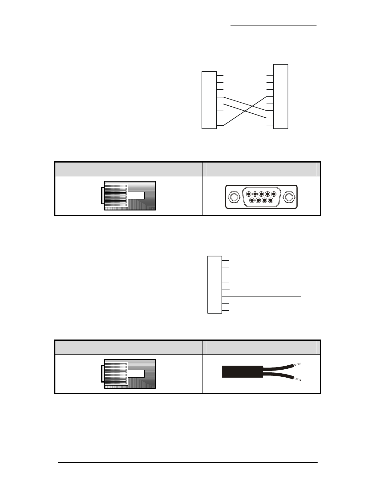
5.2 PROBRIDGE TO PC CABLE
Part Number : 4310-0047B
Communication Type: RS232
Connector Type: RJ-45, DB9F
Cable Required: 6 Foot RJ-45 to DB9F
RS232 Cable (Supplied). Connects
ProBridge to the serial port of a PC.
NOTE: This cable is used for Programming
ProBridge via HyperTerminal
Pin 8
Pin 7
Pin 6
Pin 5
Pin 4
Pin 3
Pin 2
Pin 1
RJ-45
Connecto
r
DB-9F
Connector
Pin 8
Pin 7
Pin 6
Pin 5
Pin 4
Pin 3
Pin 2
Pin 1
Pin 9
RJ-45 Connector DB9F Connector
5.3 PROBRIDGE TO I/O JUNCTION BOX OR CYBERDOMES
Part Number : 4310-0032A
Communication Type: RS485
Connector Type: RJ45, Flying Leads
Cable Required: RS-485 Flying Leads
Cable. Interconnects ProBridge with
KTD-405 and Dome Cameras.
Pin 8
Pin 7
Pin 6
Pin 5
Pin 4
Pin 3
Pin 2
Pin 1
RJ-45 Flying
L
eads
Black
Red
Connector
RJ45 Connector Flying Leads
Page 12
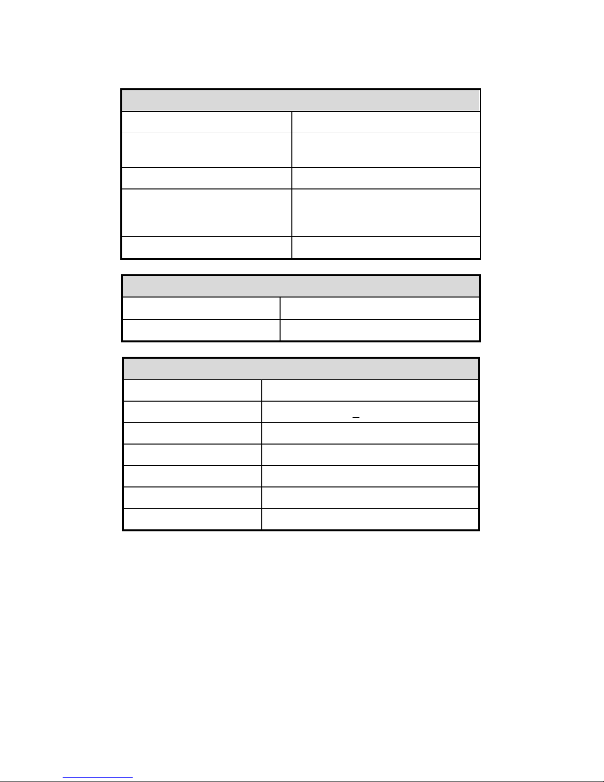
6 SPECIFICATIONS
Physical
Housing
Metal enclosure.
Dimensions
(W x L x H)
4.0” x 7.0” x 1.0”. (100mm x
175mm x 25 mm)
Nominal Weight
4.8 oz (136 g)
Shipping Weight
1 lb (453 g) packaged, including
the external AC power supply and
manual.
Color
Black.
Environmental
Temperature
0 to 40 °C, operating.
Relative Humidity
90%, non-condensing.
Electrical
AC Power
External AC power supply included.
Voltage Range:
110 to 240 VAC
+ 10%
Current:
200 mA
DC Power
DC jack, positive center.
Power Supply Voltage:
12 VDC
Current:
110 mA
Power:
1.5 W
Note: All specifications are subject to change without notice. GE believes that all
specifications are correct, however no liability is assumed for omissions or errors.
Page 13
Contacting technical support
For assistance installing, operating, maintaining, and
troubleshooting this product, refer to this document and any other
documentation provided. If you still have questions, you may
contact technical support during normal business hours (Monday
through Friday, excluding holidays, between 5 a.m. and 5 p.m.
Pacific Time).
Note: Be ready at the equipment before calling for technical support.
Online publication library
Another great resource for assistance with your GE product is our
online publication library. To access the library, go to our website
at the following location:
http://www.gesecurity.com
In the Customer Support menu, select the Publication Library
link. After you register and log on, you may search through our
online library for the documentation you need.
1
Table 1. Sales and support contact information
Sales Technical support
Phone:
Toll-free: 888.GESECURity (888.437.3287) in the US, including
Alaska and Hawaii; Puerto Rico; Canada.
Outside the toll-free area: 503.885.5700.
E-mail
Fax
800.483.2495 541.752.9096 (24 hours/day)
1. Many GE documents are provided as PDFs (portable document format).
To read these documents, you will need Adobe Acrobat Reader, which
can be downloaded free from Adobe’s website at www.adobe.com.
Page 14

Page 15

Page 16

 Loading...