

GE PRO AIR 107, PRO AIR I109, PRO AIR 109, PRO AIR I112, PRO AIR 218 Service Manual
...
g GE Consumer & Industrial Appliances
Service Manual & Installation Manual
Split System Air Conditioner
Model numbers:
PRO AIR 107
PRO AIR 109
PRO AIR 112
PRO AIR I109
PRO AIR I112
PRO AIR 218
GE AIR 326
GE AIR 428

—1—
Summary and features
Model Remark
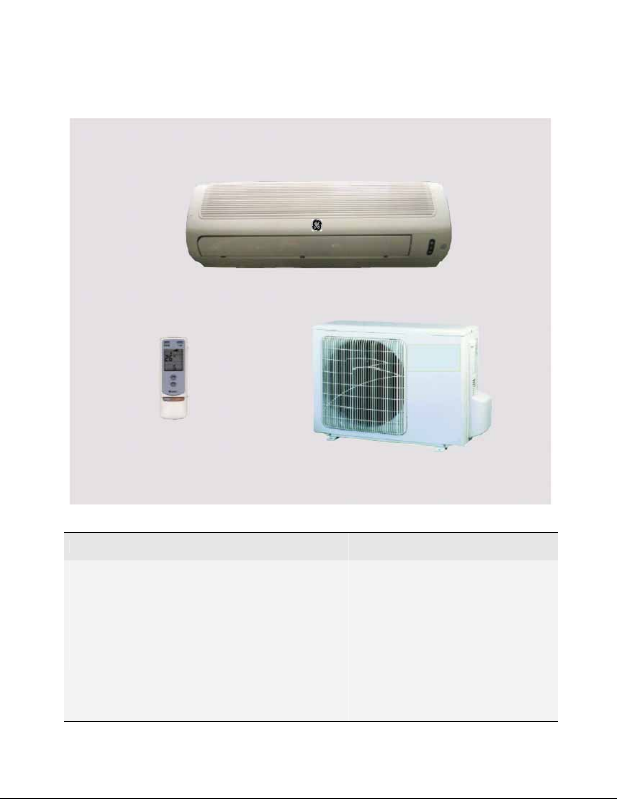
PRO AIR 107 IN / PRO AIR 107 OUT
1Ph 230V 50Hz R410A
1
—2—
Model Remark
PRO AIR 109 IN / PRO AIR 109 OUT PRO AIR 112 IN / PRO AIR 112 OUT
PRO AIR I109 IN / PRO AIR I109 OUT PRO AIR I112 IN / PRO AIR I112 OUT
1Ph 230V 50Hz R410A

—3—
Model Remark
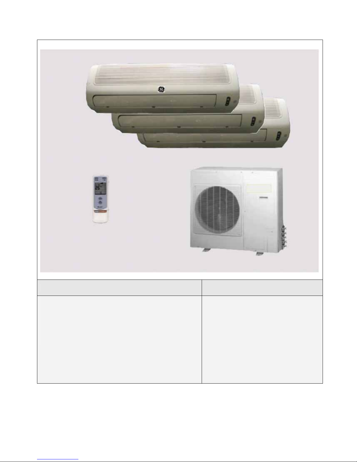
PRO AIR 218 IN / PRO AIR 218 OUT
1Ph 230V 50Hz R410A
—4—
Model Remark
GE AIR 326 IN1 / GE AIR 326 IN2 / GE AIR 326 OUT
1Ph 230V 50Hz R407C
—5—
Model Remark
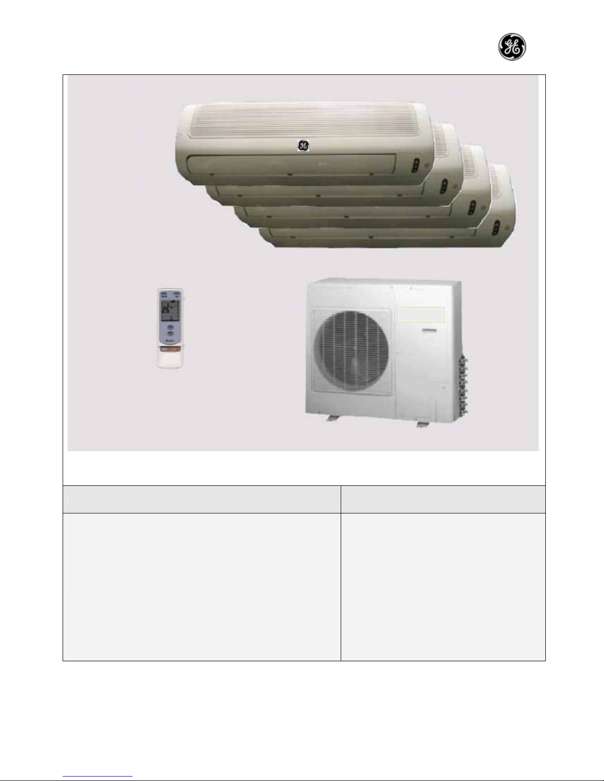
GE AIR 428 IN / GE AIR 428 OUT
1Ph 230V 50Hz R407C
—6—
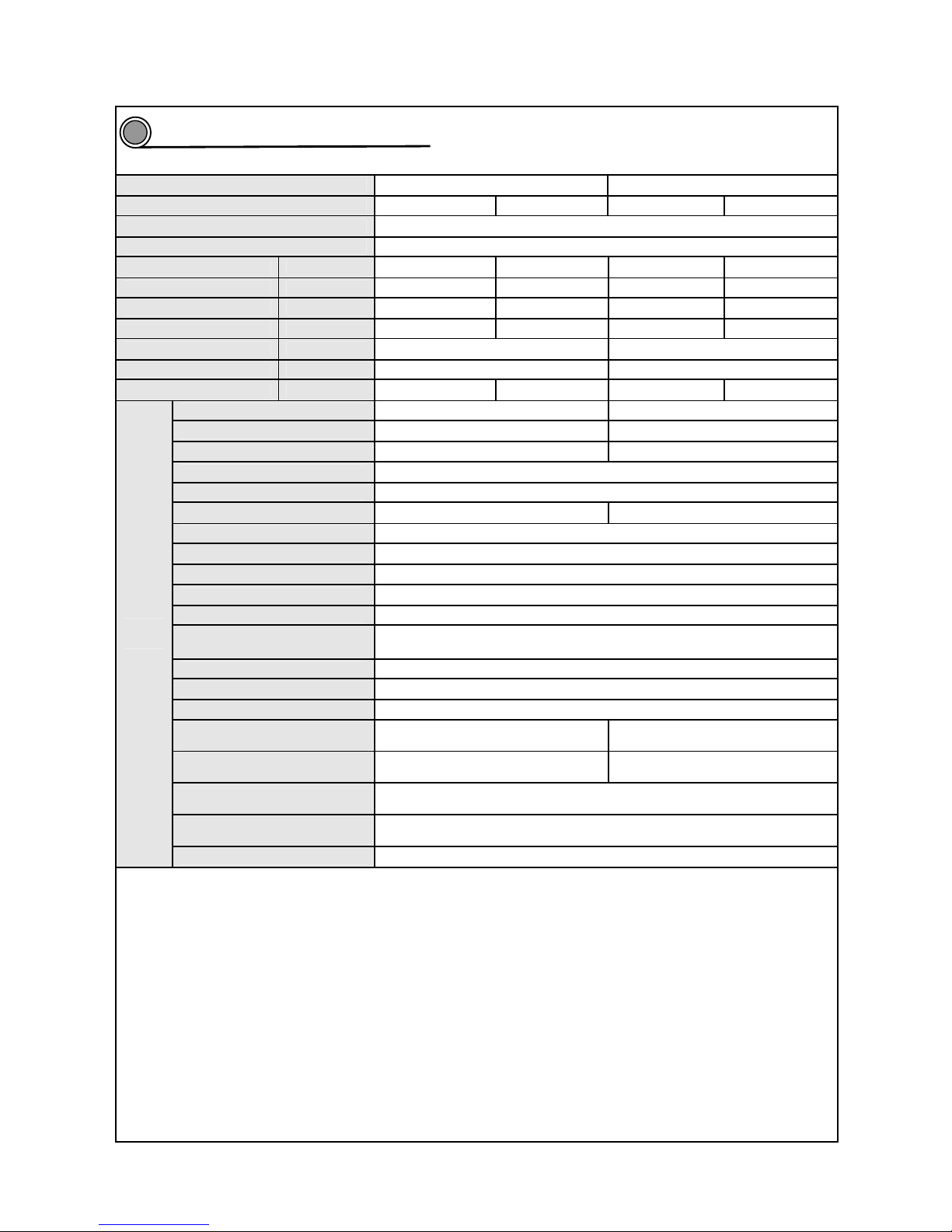
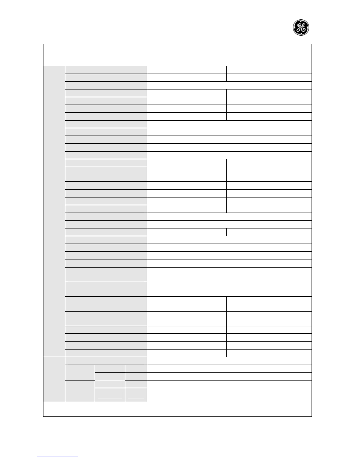
Technical and specifications
Model
PRO AIR 107 IN / PRO AIR 107 OUT PRO AIR 109 IN / PRO AIR 109 OUT
Function Cooling Heating Cooling Heating
Rated voltage 230V
Rated frequency 50Hz
Capacity (W) 2000 2200 2500 2600
Nominal power (W) 660 700 765 800
Max. power (W) 900 920 990 1050
Greatest currency (A) 4.1 4.3 4.8 5.5
Air flow (m3/h) 360 450
Dry capacity (L/h) 0.7 1.2
C.O.P/EER (W/W) 3.05 3.15 3.2 3.2
Model KFR-20G/NaA121-E KFR-25G/NaA121-E
Fan speed (r/min)(H/M/L) 1000/940/880 1160/1010/890
Output power (W) 8 14
Auxiliary electric heater power /
Fan capacitor 1
Fan motor running current 0.035 0.12
Fan type-piece
Axial flow fan-1
Diameter-length (mm) Φ97×583
Evaporator Aluminum fin-copper tube
Pipe diameter Φ7
Row-fin distance (mm) 2-1.4
Developed area of heat
exchanger (I×H×L)
580mm ×228.6mm×25.4mm
Swing motor model MP24GA
Motor power (W) 2
Fuse (A) PCB3.15A Transformer 0.2A
Noise (sound pressure level)
dB(A)
41/38/35
42/39/36
Noise (sound pressure level)
dB(A)
51/49/45
52/49/46
Outline dimension (W/D/H)
(mm)
770×180×250
Package dimension (W/D/H)
(mm)
855×270×336
Indoor
unit
Net weight/gross weight (kg) 8.5/12.5
2
—7—
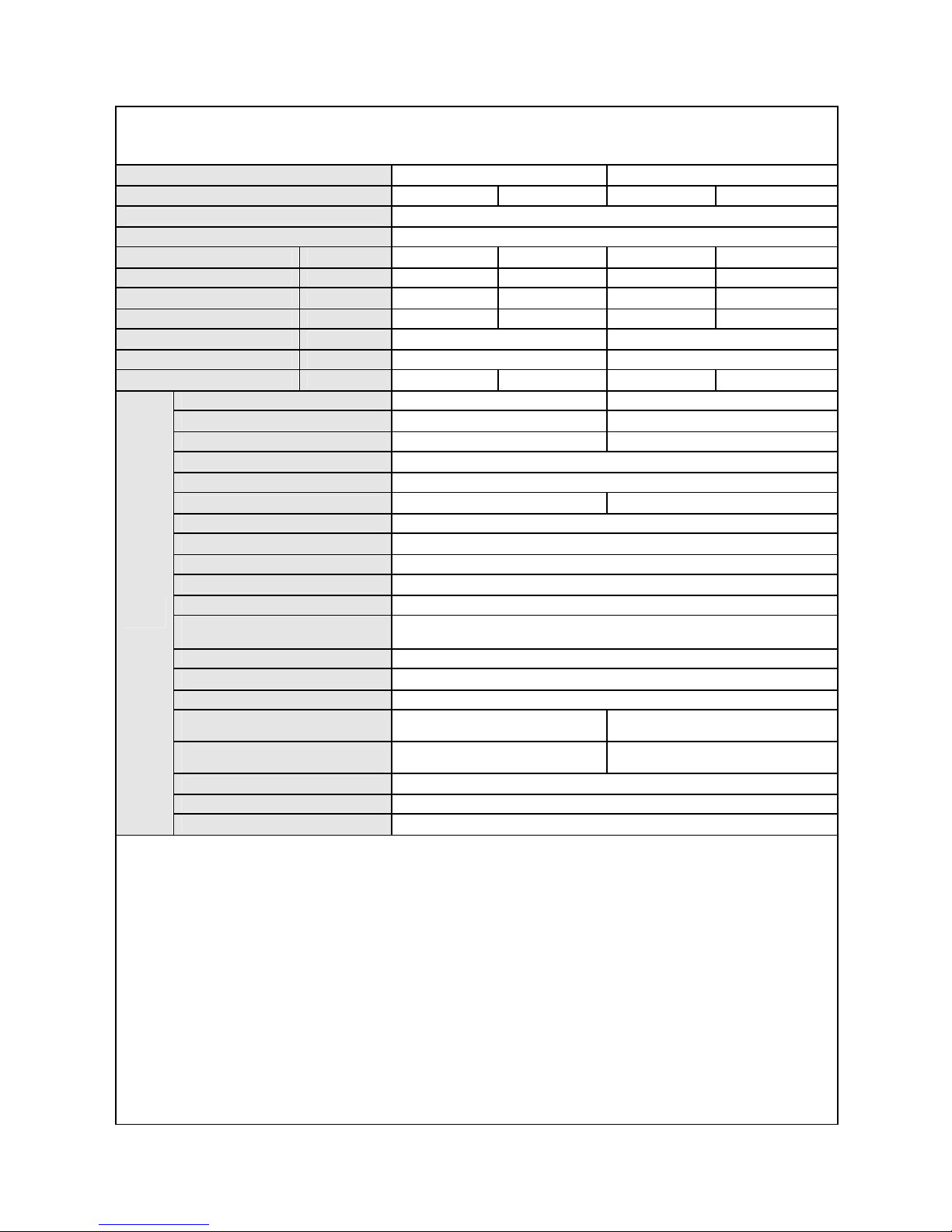
Model
PRO AIR 107 IN / PRO AIR 107 OUT PRO AIR 109 IN / PRO AIR 109 OUT
Compressor type GK080PAD C-1RV096H1A
Compressor type Rotary type
Locked rotor current 17 17
Compressor running current 3.2 3.8
Compressor input power 682 810
Compressor overload model M RA12009-12026 M RA98635-9201
Throttling method Capillary
Starting mode Capacitor CBB65 (22.5uF/450VAC)
Working temperature range -7~43℃
Condenser Aluminum fin-copper tube
Pipe diameter Φ9.52
Row-fin distance (mm) 2-1.6 2-1.4
Developed area of heat exchanger
(I×H×L)
673×406×44 791×508×44
Fan motor speed (rpm) 950 830
Motor rated power (W) 20 30
Fan motor running current (A) 0.42 0.26
Fan capacitor (μf) 1.5 2
Fan type-piece /
Fan type-piece Axial flow fan -1
Fan diameter (mm) Φ320 Φ400
Defrosting method Auto
Climate type T1
Insulation class I
Waterproof level IP24
Maximum working pressure of
exhaust side (Mpa)
3.8
Maximum working pressure of
exhaust side (Mpa)
1.2
Noise(sound pressure level)
dB(A)
52 56
Noise (sound pressure level)
dB(A)
62 66
Outline dimension (W/D/H)(mm) 660×260×430 848×320 ×540
Package dimension (W/D/H)(mm) 765×350×500 878×360 ×600
Net weight/gross weight (kg) 25/29 30/34
Outdoor
unit
Refrigerant/refrigerant charge (kg) R410A /0.88 R410A /1.1
Length 4
Liquid pipe (mm) Φ6 Outer
diameter
Gas pipe (mm) Φ9.52
Height (m) 5
Connection pipe
Maximu
m
distance
Length (m) 10
—8—
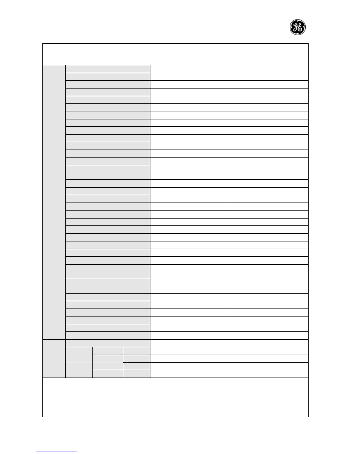
Model PRO AIR 112 IN PRO AIR I109 IN
Function Cooling Heating Cooling Heating
Rated voltage 230V
Rated frequency 50Hz
Capacity (W) 3200 3400 2500 2700
Nominal power (W) 1060 1220 730 800
Max. power (W) 1390 1370 1246 1297
Greatest currency (A) 7.2 7.4 5.7 6
Air flow (m3/h) 450 450
Dry capacity (L/h) 1.2 1.2
C.O.P/EER (W/W) 3 2.8 3.4 3.4
Model KFR-32G/NaA121-E KFR-25G/NaA12F-E
Fan speed (r/min)(H/M/L) 1160/1010/890 1190/1090/990
Output power (W) 14 14
Auxiliary electric heater power /
Fan capacitor 1
Fan motor running current 0.12 0.12
Fan type-piece Cross flow fan-1
Diameter-length (mm) Φ97×583
Evaporator Aluminum fin-copper tube
Pipe diameter Φ7
Row-fin distance (mm) 2-1.4
Developed area of heat exchanger
(I×H×L)
580mm ×228.6mm×25.4mm
Swing motor model MP24GA
Motor power (W) 2
Fuse (A) PCB3.15A Transformer 0.2A
Noise (sound pressure level)
dB(A)
42/39/36
42/39/36
Noise (sound pressure level)
dB(A)
52/49/46 52/49/46
Outline dimension (W/D/H) (mm) 770×180×250
Package dimension (W/D/H) (mm)
855×270×336
Indoor
unit
Net weight/gross weight (kg) 8.5/12.5
—9—
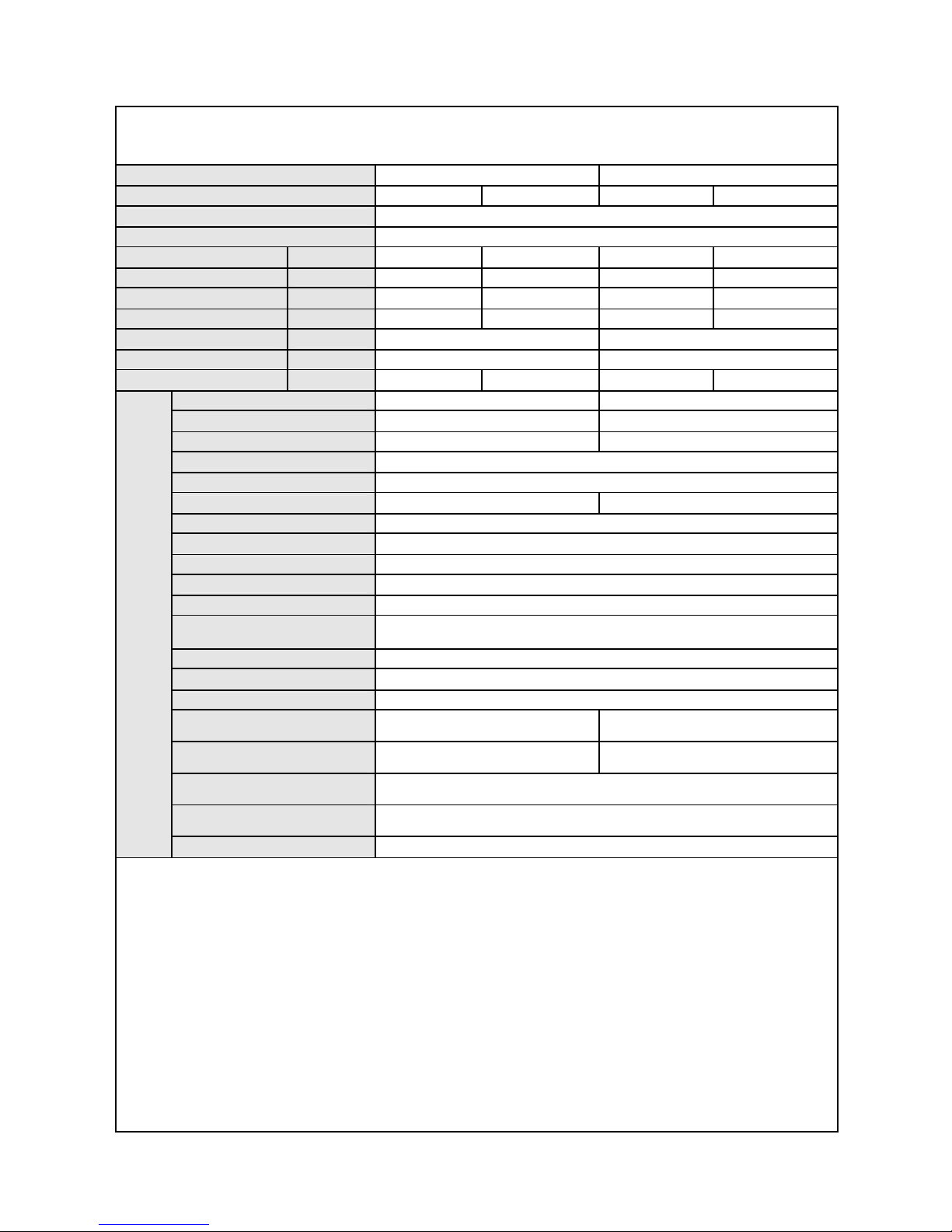
Model PRO AIR 112 OUT PRO AIR 109 OUT
Compressor type C-RV133H1A EU1011DV
Compressor type Rotary type
Locked rotor current 24 33.5
Compressor running current 5.25 4
Compressor input power 1125 628
Compressor overload model B210-145-241E 4CYC11233
Throttling method Capillary
Starting mode Capacitor
Working temperature range -7~43℃
Condenser Aluminum fin-copper tube
Pipe diameter Φ9.52
Row-fin distance (mm) 2-1.4 2-1.4
Developed area of heat exchanger
(I×H×L)
791×508×44 645×508×44
Fan motor speed (rpm) 830 830
Motor rated power (W) 30 30
Fan motor running current (A) 0.26 0.3
Fan capacitor (μf) 2.5 2.5
Fan type-piece /
Fan type-piece Axial flow fan-1
Fan diameter (mm) Φ400 Φ400
Defrosting method Auto
Climate type T1
Insulation class I
Waterproof level IP24
Maximum working pressure of
exhaust side (Mpa)
3.8
Maximum working pressure of
exhaust side (Mpa)
1.2
Noise (sound pressure level) dB(A) 56 54
Noise (sound pressure level) dB(A) 66 64
Outline dimension (W/D/H) (mm) 848×320 ×540 848×320 ×540
Package dimension (W/D/H) (mm) 878×360 ×600 878×360 ×600
Net weight/gross weight (kg) 30/34 41/43
Outdoo
r unit
Refrigerant/refrigerant charge (kg) R410A /1.3 R410A /1.2
Length 4
Liquid pipe (mm) Φ6 Outer
diameter
Gas pipe (mm) Φ9.52
Height (m) 5
Connection
pipe
Maximum
distance
Length (m) 10
—10—
Model PRO AIR I112 IN PRO AIR 218 IN
Function Cooling Heating Cooling Heating
Rated voltage 230V
Rated frequency 50Hz
Capacity (W) 3200 3400 2500×2 2800×2
Nominal power (W) 1000 1100 830×2 900×2
Max. power (W) 1361 1383 1120×2 1100×2
Greatest currency (A) 5.9 6.1 5.9×2 5.4×2
Air flow (m3/h) 450 450
Dry capacity (L/h) 1.2
1.2×2
C.O.P/EER (W/W) 3.2 3.1 3 3.1
Model
KFR-32G/NaA12F-E KFR-25X2G/NaA121-E
Fan speed (r/min)(H/M/L) 1190/1090/990 1160/1010/890
Output power (W) 14 14
Auxiliary electric heater power /
Fan capacitor 1
Fan motor running current 0.12 0.12
Fan type-piece Cross flow fan-1
Diameter-length (mm) Φ97×583
Evaporator Aluminum fin-copper tube
Pipe diameter Φ7
Row-fin distance (mm) 2-1.4
Developed area of heat
exchanger (I×H×L)
580mm ×228.6mm×25.4mm
Swing motor model MP24GA
Motor power (W) 2
Fuse (A) PCB3.15A Transformer 0.2A
Noise (sound pressure level)
dB(A)
42/39/36
42/39/36
Noise (sound pressure level)
dB(A)
52/49/46 52/49/46
Outline dimension (W/D/H)
(mm)
770×180×250
Package dimension (W/D/H)
(mm)
855×270×336
Indoor
unit
Net weight/gross weight (kg) 8.5/12.5
—11—
Model PRO AIR I112 OUT PRO AIR 218 OUT
Compressor type EU1011DV 5PS108EAA22
Compressor type Rotary type
Locked rotor current 33.5 18
Compressor running current 4 4.05
Compressor input power 628 880
Compressor overload model 4CYC11233 7100819 (KA-122-LPD021A)
Throttling method Capillary
Starting mode Capacitor
Working temperature range -7~43℃
Condenser Aluminum fin-copper tube
Pipe diameter Φ9.52
Row-fin distance (mm) 2-1.4 2-1.8
Developed area of heat exchanger (I×H
×L)
645×508×44 730×660×44
Fan motor speed (rpm) 830 815
Motor rated power (W) 30 60
Fan motor running current (A) 0.3 0.6
Fan capacitor (μf) 2.5 3
Fan type-piece /
Fan type-piece Axial flow fan-1
Fan diameter (mm) Φ400 Φ400
Defrosting method Auto
Climate type T1
Insulation class I
Waterproof level IP24
Maximum working pressure of exhaust
side (Mpa)
3.8
Maximum working pressure of exhaust
side (Mpa)
1.2
Noise (sound pressure level) dB(A) 54 60
Noise (sound pressure level) dB(A) 64 70
Outline dimension (W/D/H) (mm) 848×320 ×540 950×340×685
Package dimension (W/D/H) (mm) 878×360 ×600 1100×450×750
Net weight/gross weight (kg) 41/43 65/70
Outdoo
r unit
Refrigerant/refrigerant charge (kg) R410A /1.2 R410A /0.9×2
Length 4
Liquid pipe (mm) Φ6 Outer
diameter
Gas pipe (mm) Φ9.52
Height (m) 5
Connection
pipe
Maximum
distance
Length (m) 10
—12—
Model
GE AIR 326 IN1 / GE AIR 326 IN2 / GE
AIR 326 OUT
GE AIR 428 IN / GE AIR 428 OUT
Function Cooling Cooling
Rated voltage 230V
Rated frequency 50Hz
Capacity (W)
6800 (3200+1800×2) 7200 (1800X4)
Nominal power (W) 6800 (3200+1800×2) 2900 (1450X2)
Max. power (W)
3400 (1700×2) 3400 (1700X2)
Greatest currency (A) 6.5+6.5 6.5+6.5
Air flow (m3/h) 450 450
Dry capacity (L/h) 1.2×2 1.2×2
C.O.P/EER (W/W) 2.4 2.5
Model
KF-18X2G/NA12-E /
KF-32G/NA12-E
KF-18X4G/NA12-E
Fan speed (r/min) (H/M/L) 1160/1010/890 1160/1010/890
Output power (W) 14 14
Auxiliary electric heater power /
Fan capacitor 1
Fan motor running current 0.12 0.12
Fan type-piece Cross flow fan-1
Diameter-length (mm) Φ97×583
Evaporator Aluminum fin-copper tube
Pipe diameter Φ7
Row-fin distance (mm) 2-1.4
Developed area of heat
exchanger (I×H×L)
580mm ×228.6mm×25.4mm
Swing motor model MP24GA
Motor power (W) 2
Fuse (A) PCB3.15A Transformer 0.2A
Noise (sound pressure level)
dB(A)
42/39/36
42/39/36
Noise (sound pressure level)
dB(A)
52/49/46
52/49/46
Outline dimension (W/D/H) (mm) 770×180×250
Package dimension (W/D/H)
(mm)
855×270×336
Indoor
unit
Net weight/gross weight (kg) 8.5/12.5
—13—
Model
GE AIR 326 IN1 / GE AIR 326 IN2 /
GE AIR 326 OUT
GE AIR 428 IN / GE AIR 428 OUT
Compressor type C-RV237H01AA C-RV237H01AA
Compressor type Rotary type
Locked rotor current 31 31
Compressor running current 6.3 6.3
Compressor input power 1100 1100
Compressor overload model MRA98619-9200 MRA98619-9200
Throttling method Capillary
Starting mode Capacitor
Working temperature range -5~43℃
Condenser Aluminum fin-copper tube
Pipe diameter Φ9.52
Row-fin distance (mm) 2-1.8 2-1.8
Developed area of heat exchanger
(I×H×L)
791×508×44 791×508×44
Fan motor speed (rpm) 780 780
Motor rated power (W) 60 60
Fan motor running current (A) 0.56 0.56
Fan capacitor (μf) 3 3
Fan type-piece /
Fan type-piece Axial flow fan-1
Fan diameter (mm) Φ460 Φ460
Defrosting method Auto
Climate type T1
Insulation class I
Waterproof level IP24
Maximum working pressure of
exhaust side (Mpa)
2.5
Maximum working pressure of
exhaust side (Mpa)
0.6
Noise (sound pressure level) dB(A) 58 58
Noise (sound pressure level) dB(A) 68 68
Outline dimension (W/D/H) (mm) 950×412 ×840 950×412 ×840
Package dimension (W/D/H) (mm) 1100×450×920 1100×450×920
Net weight/gross weight (kg) 72/77 72/77
Outdoo
r unit
Refrigerant/refrigerant charge (kg) R407C /1.27×2 R407C /1.27×2
Length Length of connecting tube
Liquid
pipe
(mm) Φ6 Outer
diameter
Gas pipe (mm) Φ9.52
Height (m) 5
Connection pipe
Maximum
distance
Length (m) 10
The above data is subject to change without notice. Please refer to the nameplate of the unit.
—14—
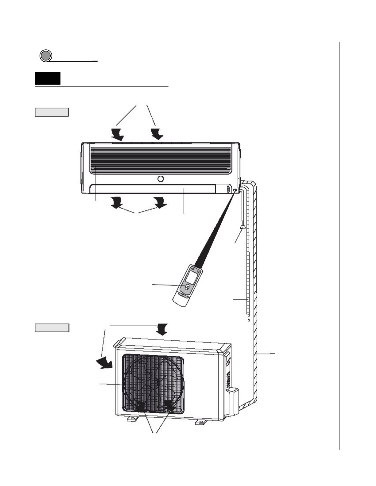
Part name
Part name of one driving one unit
Air in
Indoor unit
Panel
Air out Air guide board
Power plug
Remote controller
Drainage pipe
utdoor unit Air in
Connecting pipe and
connecting wire
Air outlet vent grill
Air out
3
3.1
—15—
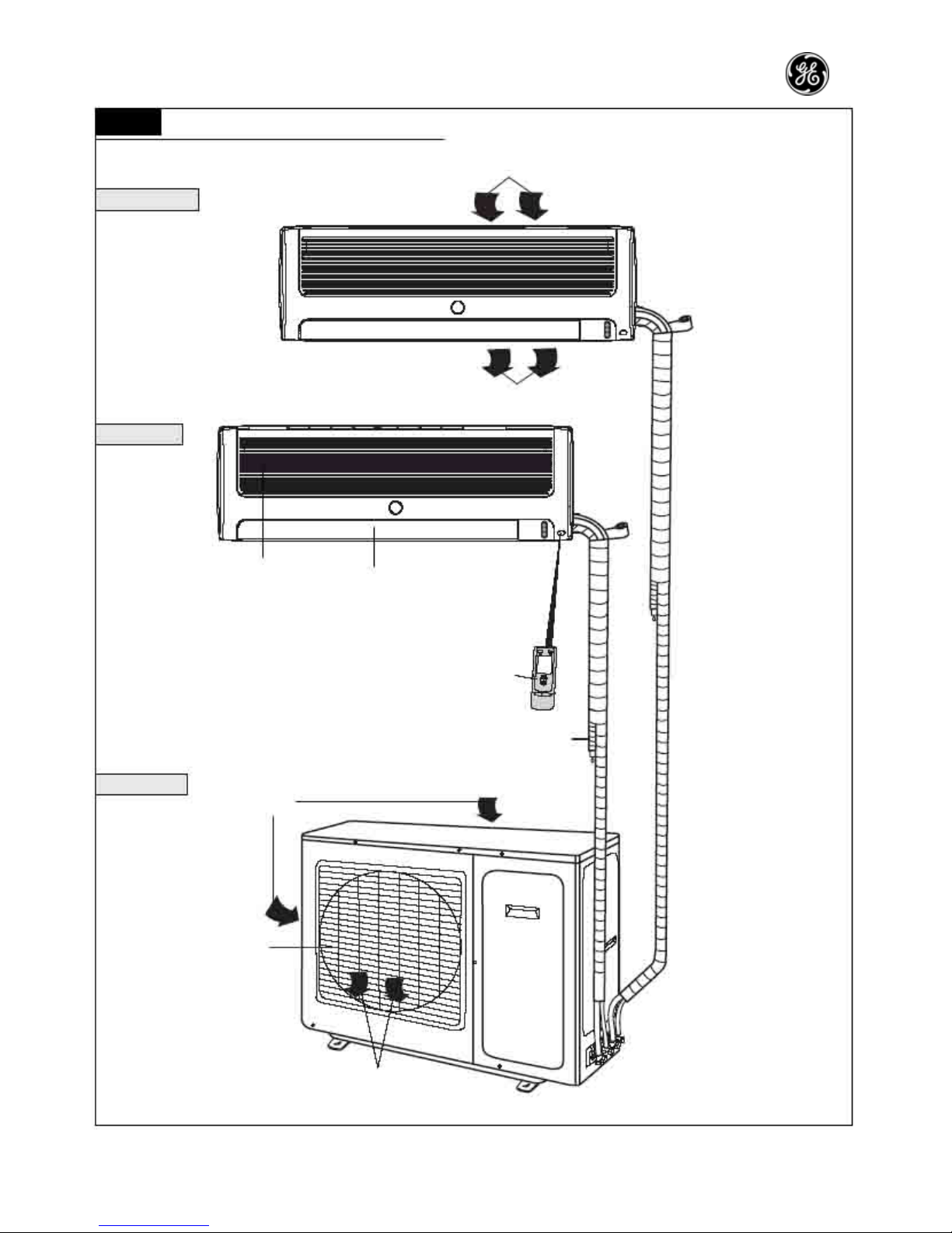
3.2 Part name of one driving two unit
Air in
Indoor unit A
Wrapping tape
Air out
Indoor unit B
Panel
Air guide board
Remote controller
Drainage pipe
Outdoor unit
Air in
Air outlet vent grill
Air out
—16—
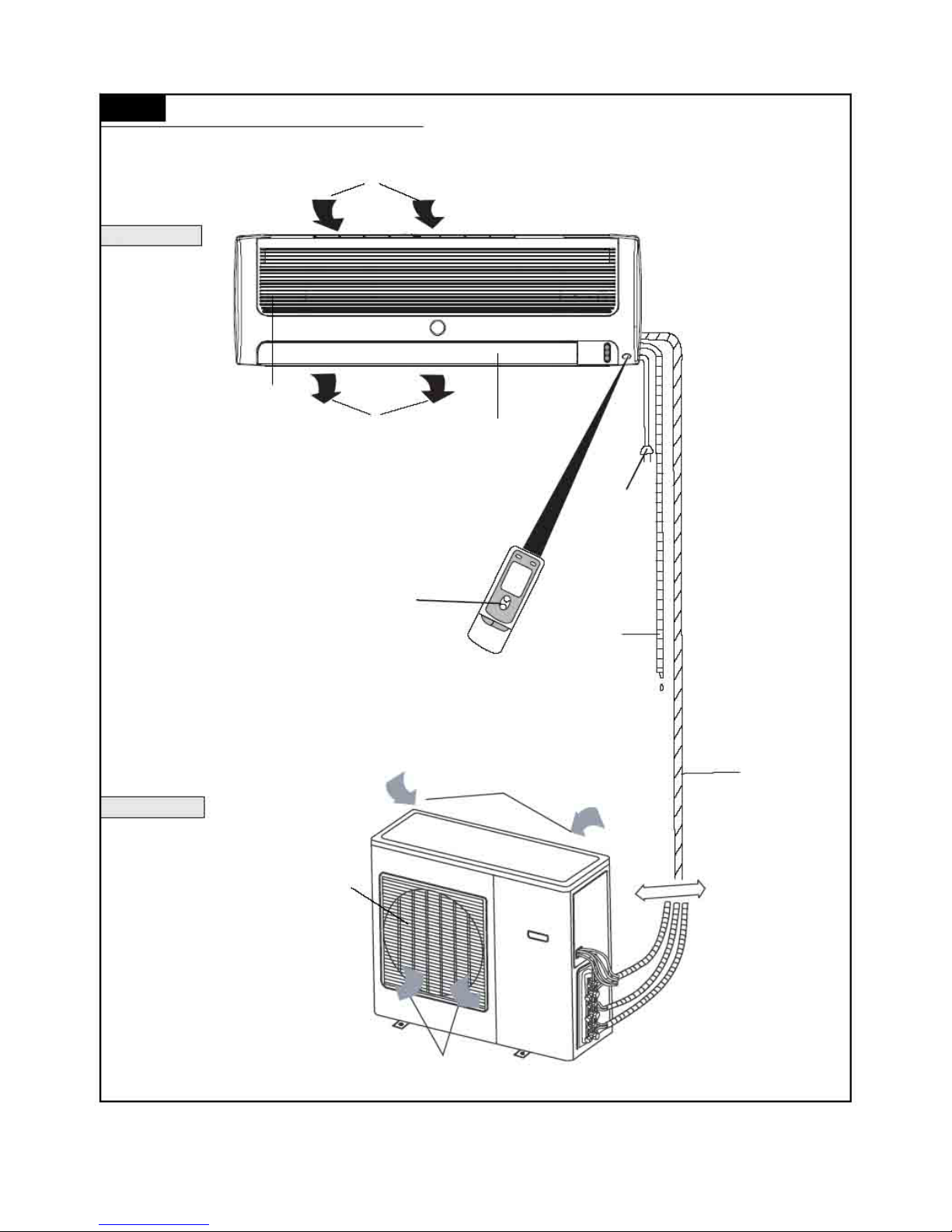
3.3 Part name of one driving three unit
Air in
Indoor unit
Panel
Air out Air guide board
Power plug
Remote controller
Drainage pipe
Air in
Outdoor unit
Air outlet vent grill
Air out
Connecting
pipe and
connecting
wire
—17—
P17
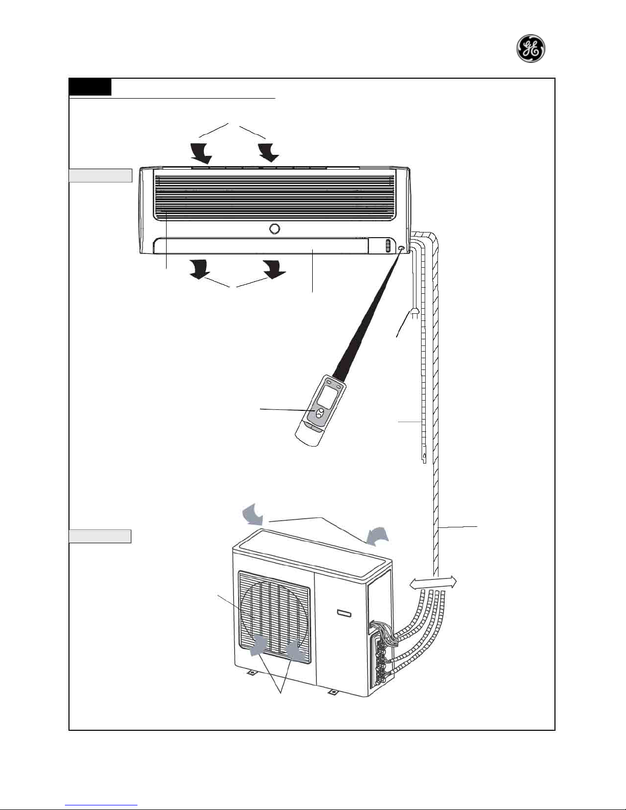
3.4
Part name of one driving four unit
Air in
Indoor unit
Panel
Air out Air guide board
Power plug
Remote controller
Drainage pipe
Air in
Outdoor unit
Air outlet vent grill
Air out
Connecting
pipe and
connecting
wire
—18—
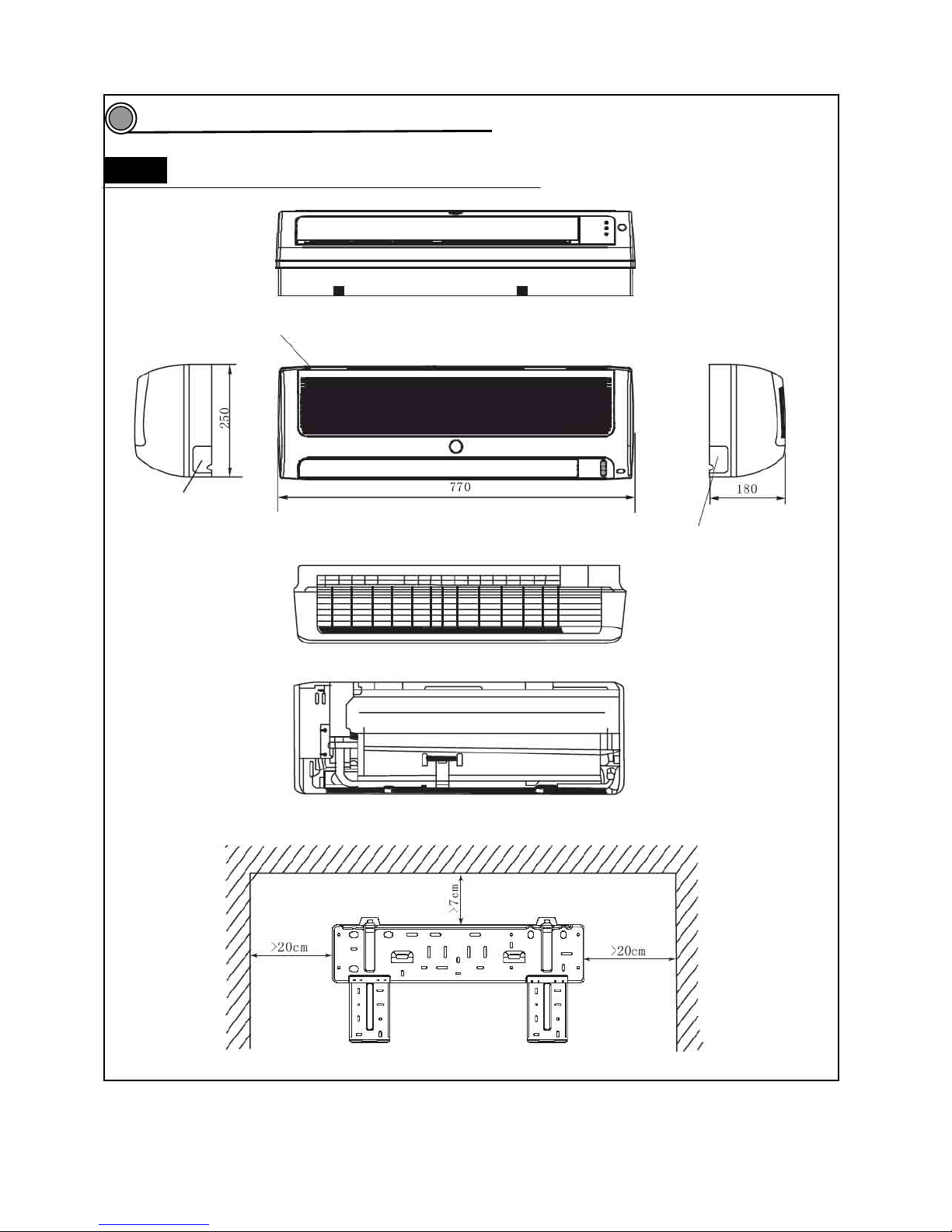
Outline and installation dimensions
4.1 Outline and installation dimensions of indoor unit
Air inlet vent
Left pipe outlet
Right pipe outlet
Rear view
Ceiling
Left side Right side
Installation dimensions
4
—19—
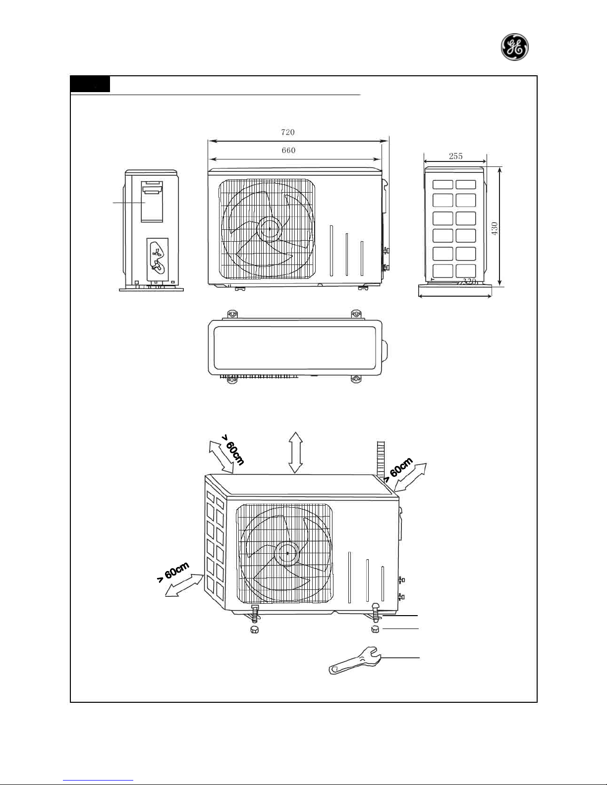
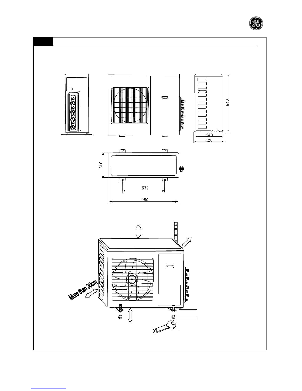
4.2 Outline and installation dimensions of indoor unit 20
Handle
> 60cm
Bolt
Nut
Spanner
—20—
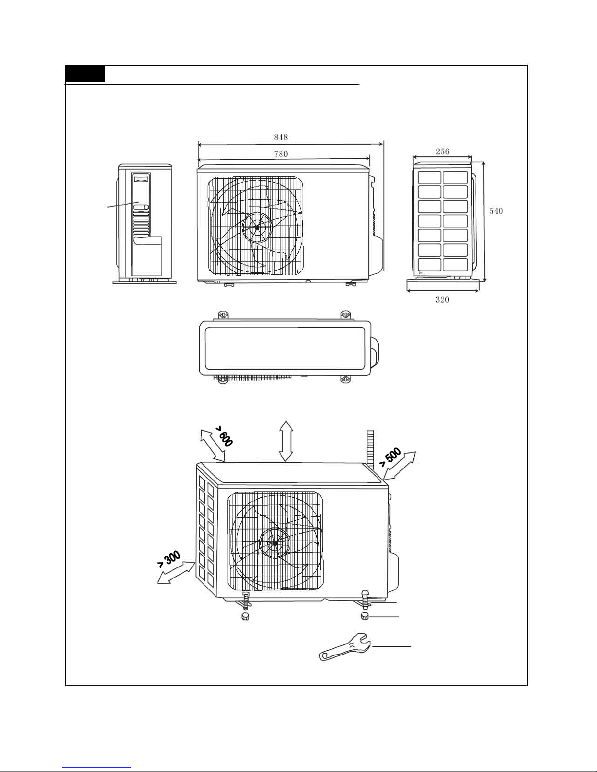
4.3 Outline and installation dimensions of indoor units 2 5, 32
Handle
Unit: mm
> 500
Bolt
Nut
Spanner
—21—
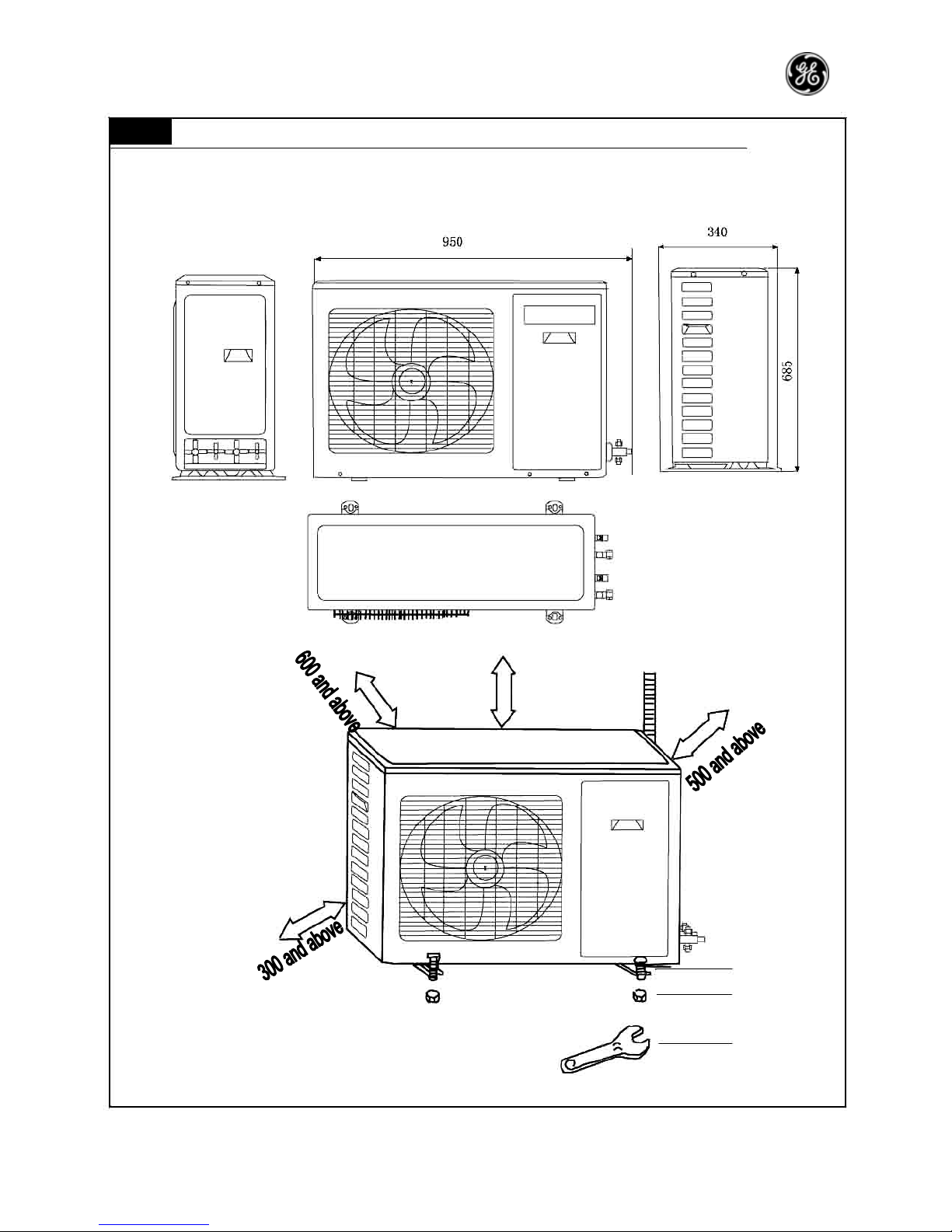
4.4 Outline and installation dimensions of one driving two outdoor unit
Unit: mm
500 and above
Bolt
Nut
Spanner
—22—
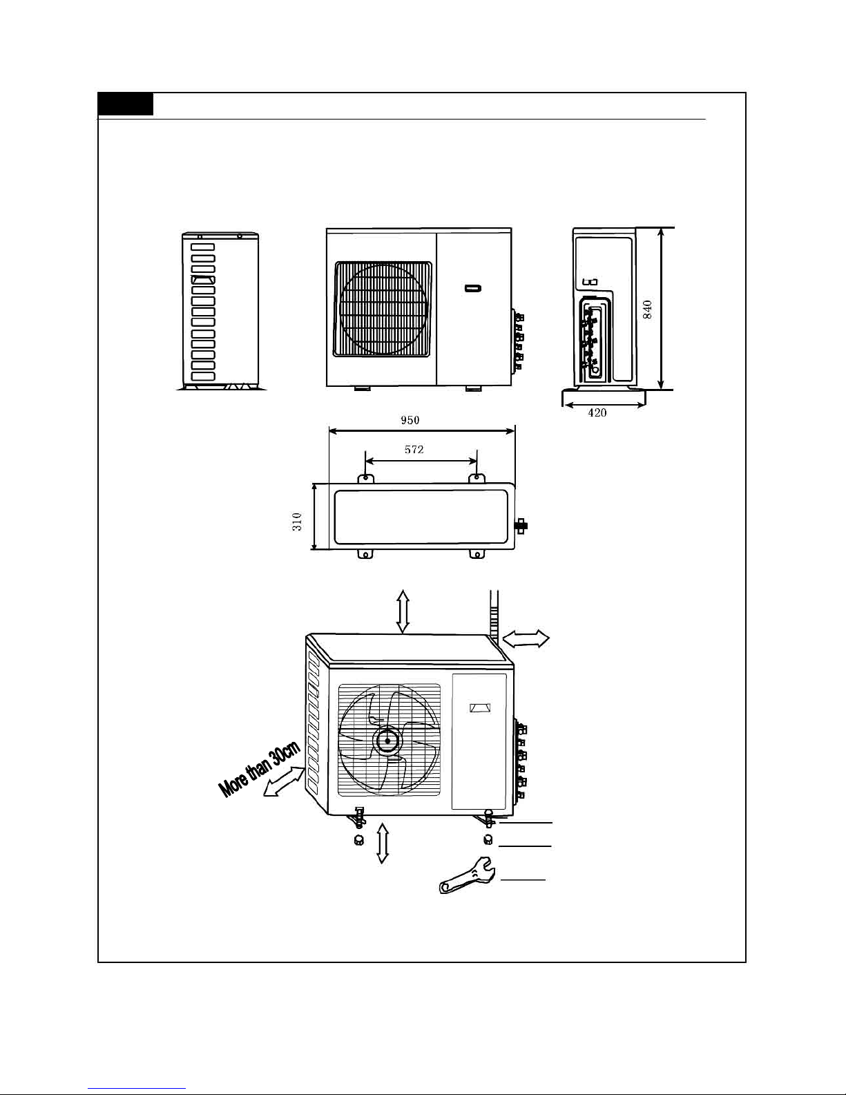
4.5 Outline and installation dimensions of one driving three outdoor unit
More than 50cm
More than 30cm
Bolt
More than 200cm Nut
Spanner
—23—
4.6 Outline and installation dimensions of one driving four outdoor unit
More than 50cm
More than 30cm
Bolt
More than 200cm Nut
Spanner
—24—
5
System diagram
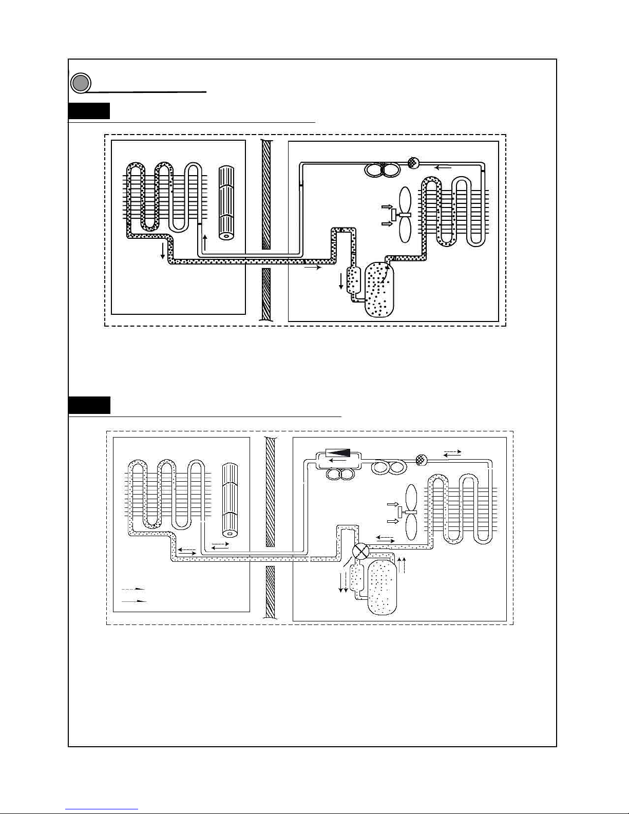
5.1 Cool only system circuit diagram
Evaporator Cross flow fan
Capillary Filter
Axial flow fan
Condenser
Gas liquid
separator Compressor
When the power is on, indoor and outdoor units will start to run. The compressor sucks low-pressure refrigerant gas from
the evaporator of indoor unit and then discharges high-temperature, high-pressure refrigerant gas into outdoor
condenser. Then air exchanges the heat with outdoor air and becomes refrigerant liquid. The liquid is throttled by the
capillary and changes into low-temperature and low-pressure liquid and then flows into indoor evaporator. Then liquid
exchanges the heat with the required air and changes into low-temperature and low-pressure refrigerant gas. The cycle
introduced above goes on and on, and the demanded low temperature environment is maintained
5.2 Cool/Heat system circuit diagram
Evaporator Cross flow fan
Flow direction of refrigerant when heating
Flow direction of refrigerant when cooling
One-way valve
Main capillary Filter
Auxiliary Capillary
Axial flow fan
Condenser
Electromagnetic
four-way valve
Gas liquid
Separator Compressor
When the power is on, indoor and outdoor units will start to run. When the system operates in cool mode, the
compressor sucks low-temperature, low-pressure refrigerant gas from indoor evaporator and then discharges
high-temperature, high-pressure refrigerant gas into outdoor heat exchanger. With the help of axial flow fan, the gas
transfers its latent heat into outdoor air and becomes high-pressure refrigerant liquid. The liquid is throttled by the
capillary and changes into low-temperature and low-pressure liquid and then flows into indoor heat exchanger. With the
help of centrifugal fan, the liquid evaporates into low-temperature refrigerant gas and indoor air is cooled down. The
refrigerant gas is sucked into the compressor and the cycle introduced above goes on and on, and the demanded low
temperature environment is maintained. When the system operates in heat mode, four-way valve changes its way and
the refrigerant flows into the reversible cycle as the cool mode. The refrigerant discharges its latent heat in the indoor
heat exchanger, and sucks heat from outdoor heat exchanger and forms the heat pump cycle. This cycle goes on and on,
and the demanded high temperature environment is maintained.
5
—25—
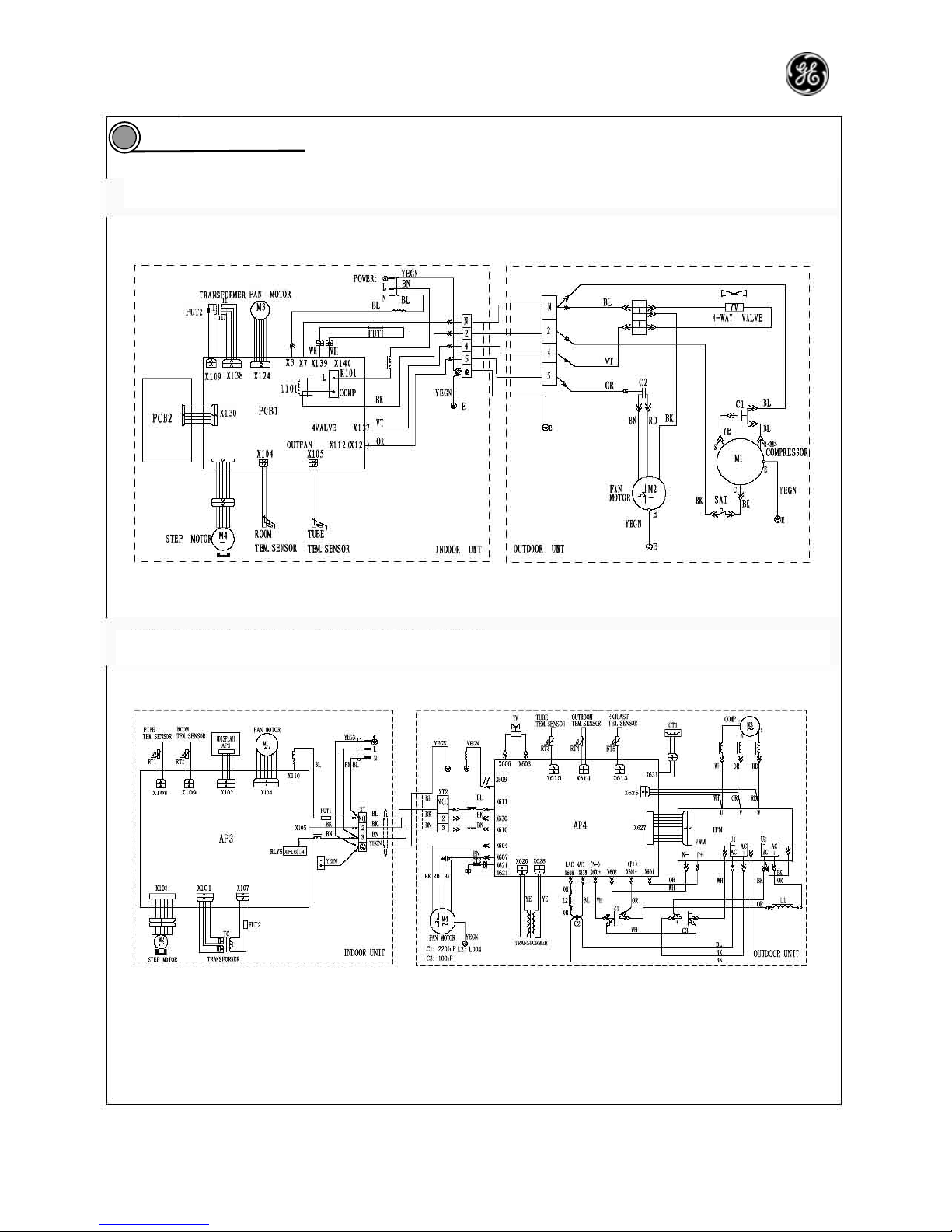
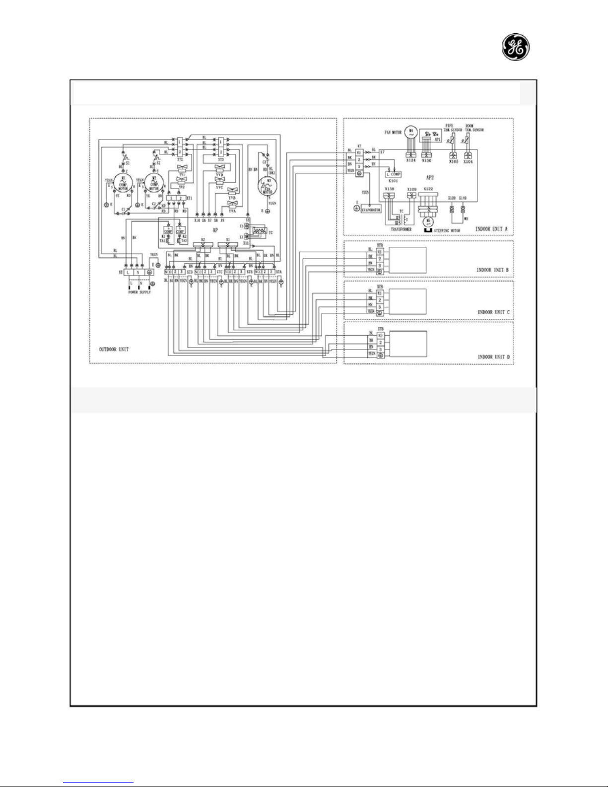
Circuit diagram
6
PRO AIR 107 IN / PRO AIR 107 OUT; PRO AIR 109 IN / PRO AIR 109 OUT; PRO AIR 112 IN / PRO
PRO AIR I109 IN / PRO AIR I109 OUT; PRO AIR I112 IN / PRO AIR I112 OUT
—26—
Circuit
diagram is
same as
above.
Circuit
diagram is
same as
above.
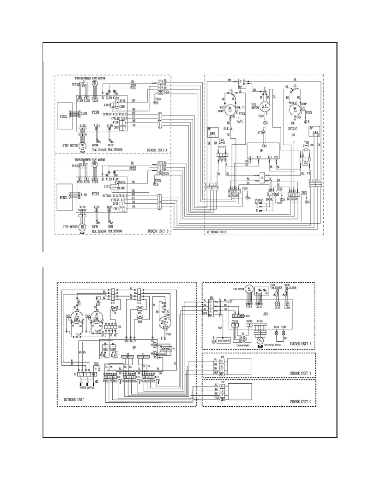
PRO AIR 218 IN / PRO AIR 218 OUT
GE AIR 326 IN1 / GE AIR 326 IN2 / GE AIR 326 OUT
—27—
Circuit
diagram is
same as
above.
Circuit
diagram is
same as
above.
Circuit
diagram is
same as
above.
These circuit diagrams are subject to change without notice. Please refer to the one supplied with the unit.
GE AIR 428 IN / GE AIR 428 OUT
—28—
Function manual and operation method of remote controller
PRO AIR I112 IN / PRO AIR I112 OUT, suitable for frequency converter
Function manual of remote controller
7.1.1 Temperature parameter
Room set temperature: (T
set
)
Room ambient temperature: (T
amb
)
7.1.2 Basic function of system
No matter what mode the compressor is in, the minimum time interval between two startups should be 3
minutes after it is powered on.
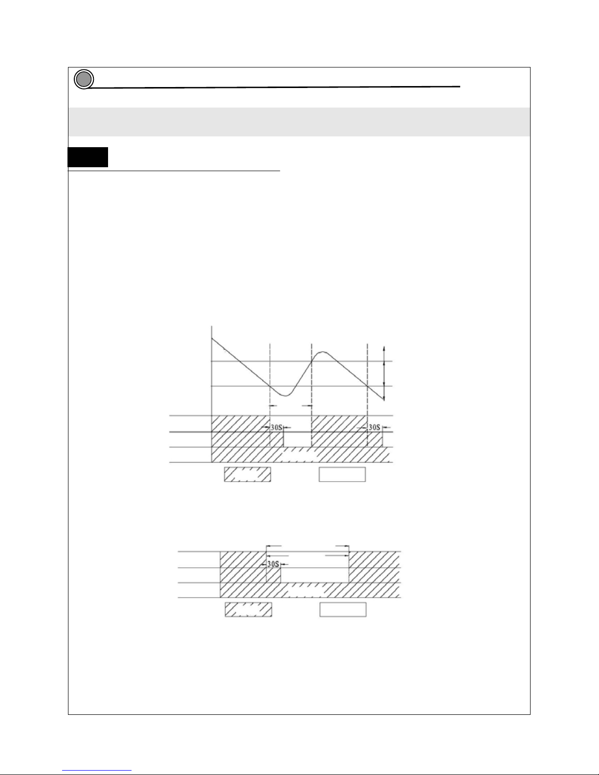
7.1.2.1 Cooling mode
7.1.2. 1.1 The condition and process of cooling
If T
amb>Tset
, COOL mode will act, compressor and external fan will run, the indoor fan will run at the set
speed.
If T
amb≤Tset
-2℃, compressor will stop and external fan will stop after a delay of 30s. The indoor fan will
run at the setting speed.
If Tset-2℃<T
amb<Tset
, the unit will keep ℃ on running in the original mode.
¾ In this mode, the reversal valve will not be powered on and the temperature setting range is
16 ~30℃℃.
T
set
+1℃ T
amb
Start cooling
T
set
-1℃ Keep running in the original mode
Stopping cooling
≥3min
Compressor
Outdoor fan
Indoor fan Set fan speed
Run Stop
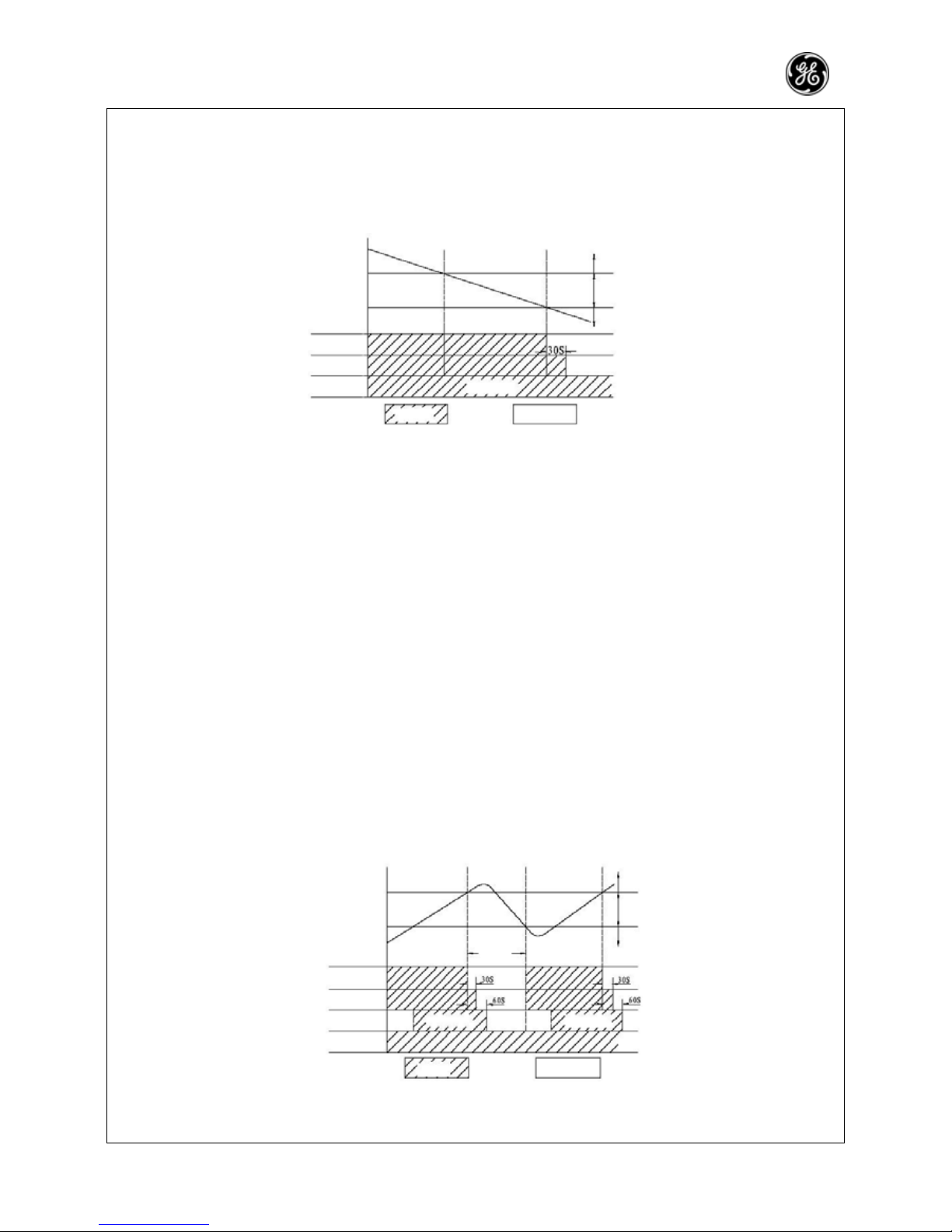
7.1.2.1.2 Protection function
Anti-freezing Protection
When the anti-freezing protection is detected, the compressor will stop, the outdoor fan will stop after a
delay of 30 seconds. The indoor fan and swing motor will keep on running in the original mode. When
anti-freezing protection is eliminated and compressor has stopped for 3min, the machine restores its
former operation mode.
Anti-freezing Protection
Compressor ≥3min
Outdoor fan
Indoor fan Set fan speed
Run Stop
Over current protection
The compressor will run at a limited frequency when the total current is high. The compressor will stop
when the total current is too high and the outdoor unit will stop after a delay of 30s.
7.1.2.2 Dry mode
7.1.2.2.1 The condition and process of dry mode
If T
amb>Tset
, the drying mode will act. The compressor and external fan will run, and the indoor fan will run
at a low speed.
7
7.1
—29—
If T
set
-2℃≤T
amb≤Tset
, the unit will keep on running in the original mode.
If T
amb≤Tset
-2℃, the compressor will stop. The external fan will stop after a delay of 30s, and the indoor
fan will run at a low speed.
¾ In this mode, the reversal valve will not be powered on and the temperature setting range is
16 ~30℃℃
T
amb
T
set
T
set
-2℃
Compressor
Outdoor fan
Indoor fan Low fan speed
Run Stop
Cooling running
Dry running
Stop running
7.1.2.2.2 Protection function
Anti-freezing protection
Anti-frost protection same as cooling
Over current protection
Over current protection is the same as the cooling mode.
7.1.2.2.3 SWING mode
At this mode, the inner fan will select among high, medium, low and auto modes and the compressor,
outer fan and 4-way fan will stop running.
¾ In this mode, the reversal valve will not be powered on and the temperature setting range is
16 ~30℃℃
7.1.2.3 HEAT mode
7.1.2.3.1 Running condition and process of heating mode
If T
amb≤Tset
+2 , HEAT mode will act, the compressor, outdoor fan and reversal valve will run at the same ℃
time, the indoor fan will run after 3 minutes’ delay at the latest.
If T
amb≥Tset
+4 , the compressor will stop℃ first and 15s later, the outdoor unit will stop. The reversal valve
will keep power-on and the indoor fan will run at a low speed and will stop 30s later.
If T
set
+2℃<T
amb<Tset
+4 ,℃ the unit will keep running in the previous mode.
¾ In this mode, the temperature setting range is 16 ~30 .℃℃
¾ The air conditioner will adjust the running frequency of the compressor automatically according to the
change of ambient temperature.
¾ The 4-way valve will be cut off 2min after the compressor stops operation when heating cut-off, or
heating mode changed to other mode.
T
set
+5℃
T
set
+2℃ T
amb
≥3min
Stop heating
Original running state
Start heating
Compressor
Outdoor fan
Indoor fan ≤3min Set fan speed ≤3min Set fan speed
Reversal valve
Run Stop
7.1.2.3.2 The condition and process of defrosting
When frost is detected in the condenser, the system will enter into defrosting mode. When the defrosting starts,
the compressor and indoor fan stop running. The outdoor fan will stop after a delay of 30s, and the four-way
 Loading...