

GE PrecisionLine RCR-90 Installation Instructions Manual
PrecisionLine
RCR-90
Preliminary
Dual T echnology Motion Sensor
Installation Instructions
Description
The RCR-90 combines range-controlled radar (RCR) technology
with a passive infrared (PIR) system to increase false alarm
immunity by allowing it to sense human-sized objects within a
specified range. Both the RCR and PIR systems must be triggered
to set off an alarm, unless in radar-only mode.
The detector is designed to use a 12VDC power supply provided
by a UL Listed alarm control panel.
Features
The detector provides the following features:
• High-security (radar-only) mode - Internal jumper allows you
to disable the PIR, and use the radar-only mode to detect
intruders faster. This mode can be used for covert installations
(mounted behind ceiling panels or walls).
• Selectable range up to 90 feet (27.4m) - Internal jumper
allows radar range selection to optimize coverage.
• LED indicator - A multi-color LED provides detector status.
• Tamper switch - Activated when the pins on the circuit board
are removed from the terminal sockets on the base.
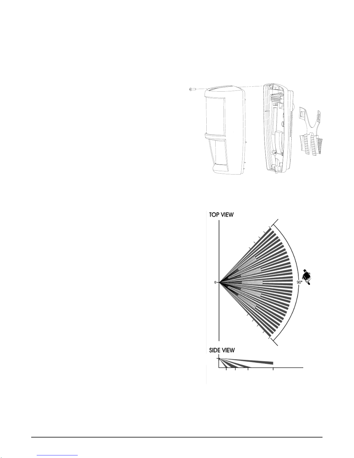
Closing screw
August 7, 2003
BaseFront cover/electronic module
Bracket
Figure 1. Detector (Exploded)
90’(27m)
80’(24m)
70’(12m)
60’(18m)
50’(15m)
Selecting a Location for the
Detector
The detector can be mounted in a corner or on a flat wall. Use the
following guidelines to determine the best location to install the
detector:
• Mount the detector so the expected movement of an intruder is
across the detection pattern. See Figure 2.
• Mount the detector on a stable surface 8 to 12 feet (2.4 to 3.7m)
high.
• DO NOT mount the detector within 2 feet (0.6m) of metallic
objects or within 5 feet (1.5m) of florescent lights.
• DO NOT place objects in front of the detector that may prevent
a clear line of sight. (Not applicable in radar-only mode.)
• Avoid locations that expose the detector to possible false alarm
sources such as:
– Moving or vibrating objects (fans, pulleys, conveyor belts)
– Electronic fields (electric motors, high voltage equipment)
– Water spray or corrosive environments
– Heat sources in the field of view (heaters, radiators)
– Windows in the field of view
– Strong air drafts on the detector (fans, air conditioners)
PrecisionLine RCR-90
50’(15m)
60’(18m)
70’(12m)
80’(24m)
90’(27m)
10’
(3m)
35’
(11m)
50’
(15m)
10’
(3m)
Figure 2. Coverage Pattern
• When installing multiple detectors:
– DO NOT mount detectors facing each other.
– Mount detectors at least 20 feet (6.1m) apart.
– Use shorter range settings to avoid overlapping radar coverage.
90’
(27m)
1
Installing the Detector
All wiring must conform to the National Electric Code (NEC) and/
or local codes having jurisdiction.
Important: DO NOT use this device for safety
interlock applications.
To install the detector:
1. Run the security system wiring to the detector location.
2. To remove the front cover/electronic module, remove the
closing screw. See Figure 1. Then pull out on the top of the
front cover and lift off.
CAUTION
You must be free of all static electricity before
handling sensor circuit boards. Touch a
grounded, bare metal surface before touching
circuit boards or wear a grounding strap.
3. If necessary, set the jumpers on the circuit board. See Setting
the Jumpers.
4. Remove the appropriate wiring and mounting knockouts from
the back cover. The detector can be mounted on a flat wall or
in a corner. See Figure 4.
5. Pull the wires through the knockout holes and strip 1/4 inch
(6.4mm) of insulation from each wire.
6. Run each wire through the strain relief (see Figure 4) and
under the appropriate screw terminals (see Figure 3) on the
base and tighten the screws.
7. Use screws to attach the base to the wall. Use screw anchors
if necessary. See Mounting Adjustments.
8. Line up the tabs on the bottom of the front cover/electronic
module with the corresponding tabs on bottom of the base
and push the front cover/electronic module firmly down onto
the base.
9. Tighten the closing screw . See Figure 1.
10. Apply power. The green LED should light for approximately
25 seconds and then go out.
11. Walk test the coverage pattern as follows:
– W alk throughout the intended coverage area.
– Verify the detector alarms. See Understanding the LED.
Note
Most units walk test more accurately if the person
testing waits 10 seconds between tripping the unit and
walking again. This allows the detector to stabilize
between trips.
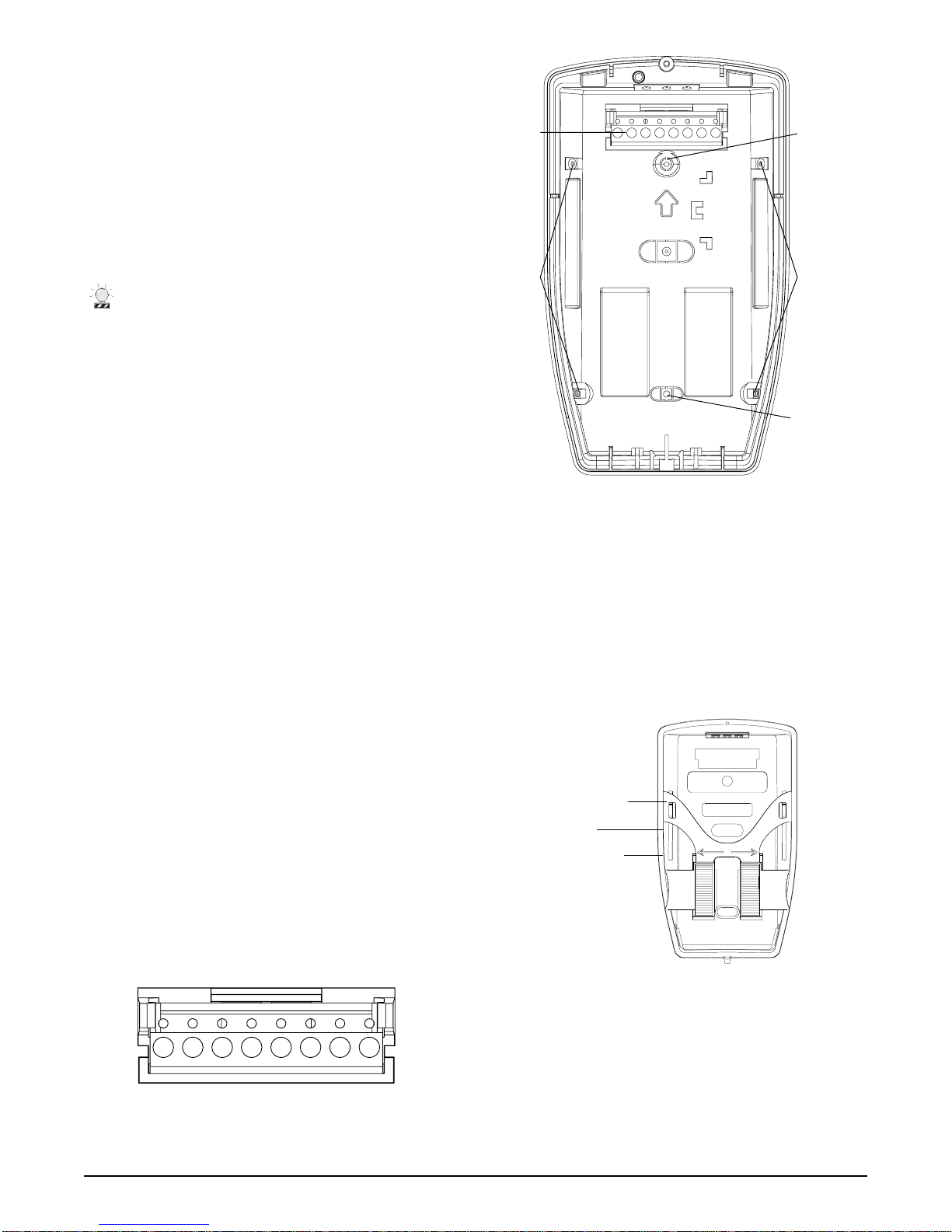
Terminal
sockets
Corner mount
knockouts
Strain
relief
Wiring knockout
Figure 4. Detector Base
Flat wall mount
knockout
Corner mount
knockouts
Flatwall mount
knockout
Mounting Adjustments
Flat Wall Mount
Mount the unit using the two flat wall mount knockouts (see
Figure 4) Use the bracket to adjust the angle of coverage for
mounting on a flat wall. See Figure 5 for the best initial bracket
setting for the mounting height used. Make sure the mounting
screws are tightened before testing the unit. If you need to make
further adjustments, loosen the bottom screw, adjust the bracket,
tighten the bottom screw, and test the unit.
12’ - one notch down
from the top
10’ - center
8’ - one notch up
from the bottom
SPR TMP TMP NO COM NC +12V GND
Figure 3. Wiring
2
Figure 5. Mounting Adjustment Bracket
Corner Mount
Mount the unit using two corner mount knockouts (see Figure 4)
on one vertical side of the unit. The top corner mount knockouts
are designed with room to adjust the coverage pattern. Mount and
tighten both corner mount screws. Test the unit. If you need to
make further adjustments, loosen the top corner mount screw,
adjust the unit, tighten the top corner mount screw, and test the
unit.
PrecisionLine RCR-90
 Loading...