

GE Power Quality Meter Series, PQM Series, PQM-T20-C-A Instruction Manual
g
GE Power Management
PQM
Power Quality Meter™
INSTRUCTION MANUAL
Software Revision: 3.5x
Manual P/N: 1665-0003-CG
Manual Order Code: GEK-106296A
Copyright © 2001 GE Power Management
g
GE Power Management
PQM Power Quality Meter
STATUS COMMUNICATE RELAYS
ALARM
PROGRAM
SIMULATION
SELF TEST
TX1
RX1
TX2
RX2
ALARM
AUX1
AUX2
AUX3
ACTUAL
SETPOINT
STORE
RESET
MESSAGE
VALUE
823787A3.CDR
215 Anderson Avenue, Markham, Ontario
Canada L6E 1B3
Tel: (905) 294-6222 Fax: (905) 294-8512
Internet: http://www.GEindustrial.com/pm
Manufactured under an
ISO9001 Registered system.


These instructions do not purpor t to cover all detai ls or varia tions in equipment nor provide fo r every p ossibl
e
e
e
t
contingency to be met in connection with installation, operation, or maintenance. Should further information b
desired or should pa rticula r pro blems arise whi ch are no t cove red su ffici ently for the p urchas er’s purpose, th
matter should be referred to the General Electric Company.
To the extent required the products des cribed herein meet applic able ANSI, IEE E, and NEMA s tandards; bu
no such assurance is given with respect to local codes and ordinances because they vary greatly.


TABLE OF CONTENTS
1. OVERVIEW
2. INSTALLATION
1.1 INTRODUCTION
1.1.1 DESCRIPTION..........................................................................................1-1
1.1.2 FEATURE HIGHLIGHTS............................................................ ...............1-1
1.1.3 APPLICATIONS.................................... .....................................................1-3
1.2 STANDARD FEATURES
1.2.1 METERING................................................................................................ 1-4
1.2.2 FUTURE EXPANSION.............................................................................. 1-4
1.2.3 OPTIONAL FEATURES............................................... ..................... ......... 1-5
1.2.4 PQMPC SOFTWARE................................................................................ 1-9
1.2.5 O R D E R C O D E S . ............ .. ........... ............ .. ........... .. ........... .. ............ .. ...... 1 - 1 0
1.3 SPECIFICATIONS
1.3.1 PQM SPECIFICATIONS..........................................................................1-11
2.1 PHYSICAL
2.1.1 MOUNTING ...............................................................................................2-1
2.1.2 PRODUCT IDENTIFICATION....................................................................2-2
2.1.3 R EVISION HIS T ORY.......... ....................... .. ........... .. ........... .. .................... 2-3
2.2 ELECTRICAL
2.2.1 EXTERNAL CONNECTIONS............. ..................... ..................... .............2-4
2.2.2 CONTROL POWER.................................... ..................... ........................ 2-13
2.2.3 VT INPUTS ............... .. ............ . ............ .. ........... .. ............ ........... .. ........... . 2-13
2.2.4 CT INPUTS.............................................................................................. 2-13
2.2.5 OUTPUT RELAYS................................................... ..................... ........... 2-14
2.2.6 SWITCH INPUTS (OPTIONAL)............................................................... 2-15
2.2.7 ANALOG OUTPUTS (OPTIONAL).......................................................... 2-17
2.2.8 ANALOG INPUT (OPTIONAL)................................................................. 2-17
2.2.9 RS485 SERIAL PORTS........................................................................... 2-18
2.2.10 RS232 FRONT PANEL PORT......................................... ..................... ...2-20
2.2.11 DIELECTRIC STRENGTH TESTING......................................................2-21
3. OPERATION
3.1 FRONT PANEL & DISPLAY
3.1.1 FRONT PANEL.......................................................................................... 3-1
3.1.2 DISPLAY.................................................................................................... 3-1
3.2 STATUS INDICATORS
3.2.1 DESCRIPTION..........................................................................................3-2
3.2.2 STATUS.....................................................................................................3-2
3.2.3 COMMUNICATE........................................................................................ 3-2
3.2.4 RELAYS..................................................................................................... 3-3
3.3 KEYPAD
3.3.1 DESCRIPTION..........................................................................................3-4
3.3.2 SETPOINT KEY.........................................................................................3-4
3.3.3 ACTUAL KEY................................ .............................................................3-4
3.3.4 STORE KEY..............................................................................................3-4
3.3.5 RESET KEY...............................................................................................3-5
3.3.6 MESSAGE KEYS........ .................................. .. ....................... .. .. ............ . .. . 3-6
3.3.7 VALUE KEYS............................................................................................. 3-6
3.3.8 DATA ENTRY METHODS....................................... ..................... ............. 3-7
3.3.9 SETPOINT ACCESS SECURITY ..............................................................3-7
GE Power Management PQM Power Quality Meter
i

TABLE OF CONTENTS
3.4 DEFAULT MESSAGES
3.4.1 DESCRIPTION ..........................................................................................3-8
3.4.2 ADDING A DEFAULT MESSAGE.............................................................3-8
3.4.3 DEL ETING A DEFAU L T MESSAGE ..... .. ......................... ............. ............ 3-8
4. PROGRAMMING
4.1 INTRODUCTION
4.1.1 SETPOINT ENTRY METHODS.................................................................4-1
4.2 S1 PQM SETUP
4.2.1 DESCRIPTION ..........................................................................................4-3
4.2.2 PREFERENCES........................................................................................4-3
4.2.3 SETPOINT ACCESS.................................................................................4-4
4.2.4 RS485/RS232 SERIAL PORTS.................................................................4-6
4.2.5 DNP 3.0 CONFIGURATION........ ..................... .........................................4-7
4.2.6 CLOCK........................................................ ..................... ..................... ..... 4-8
4.2.7 CALCULATION PARAMETERS................................................................4-9
4.2.8 CLEAR DATA ..........................................................................................4-11
4.2.9 EVENT RECORDER ...............................................................................4-13
4.2.10 TRACE MEMORY.................. ........................................ ..................... ..... 4-14
4.2.11 PROGRAMMABLE MESSAGE ...............................................................4-17
4.2.12 PRODUCT OPTIONS..............................................................................4-18
4.3 S2 SYSTEM SETUP
4.3.1 CURRENT/VOLTAGE CONFIGURATION......... .....................................4-19
4.3.2 ANALOG OUTPUTS......................................... ..................... ..................4-21
4.3.3 ANALOG INPUT............................ ..................... ..................... ................4-25
4.3.4 SWITCH INPUTS.................................. ..................... ..................... ......... 4-27
4.3.5 PULSE OUTPUT ..................................................................................... 4-29
4.3.6 PULSE INPUT .........................................................................................4-31
4.3.7 DATA LOGGER.................................... ........................................ ...........4-33
4.4 S3 OUTPUT RELAYS
4.4.1 DESCRIPTION ........................................................................................4-34
4.4.2 ALARM RELAY........................................................................................ 4-35
4.4.3 AUXILIARY RELAYS.................................. ............................................. 4-35
4.5 S4 ALARMS/CONTROL
4.5.1 CURRENT/VOLTAGE ALARMS.............................................................. 4-36
4.5.2 TOTAL HARMONIC DISTORTION............. ..................... ..................... ... 4-41
4.5.3 FREQUENCY ....................................... .......................................... ......... 4-42
4.5.4 POWER ALARMS....................................................................................4-43
4.5.5 POWER FACTOR.............. ..................... ................................................. 4-45
4.5.6 DEMAND ALARMS............ ......................................................................4-48
4.5.7 PULSE INPUT .........................................................................................4-50
4.5.8 TIME ........................................................................................................ 4-52
4.5.9 MISCELLANEOUS ALARMS...................................................................4-53
4.6 S5 TESTING
4.6.1 TEST OUTPUT RELAYS & LEDS........................................................... 4-54
4.6.2 CURRENT/VOLTAGE SIMULATION ...................................................... 4-55
4.6.3 ANALOG OUTPUTS SIMULATION.........................................................4-56
4.6.4 ANALOG INPUT SIMULATION ............................................................... 4-57
4.6.5 SWITCH INPUTS SIMULATION........... ..................... ..................... .........4-58
4.6.6 FACTORY USE ONLY............................................................................. 4-58
ii
PQM Power Quality Meter
GE Power Management

TABLE OF CONTENTS
5. MONITORING
5.1 ACTUAL VALUES VIEWING
5.1.1 DESCRIPTION..........................................................................................5-1
5.2 A1 METERING
5.2.1 CURRENT ................................................................................................. 5-2
5.2.2 VOLTAGE.................................................................................................. 5-4
5.2.3 PHASORS .................................................................................................5-6
5.2.4 POWER ..................................................................................................... 5-7
5.2.5 ENERGY..................................................................................................5-12
5.2.6 DEMAND ................................................................................................. 5-14
5.2.7 FREQUENCY ..........................................................................................5-16
5.2.8 PULSE COUNTER.................................................................................. 5-17
5.2.9 ANALOG INPUT......................................... ............................................. 5-19
5.3 A2 STATUS
5.3.1 ALARMS..................................................................................................5-20
5.3.2 SWITCH STATUS.................................................................................... 5-22
5.3.3 CLOCK..................................................................................................... 5-23
5.3.4 PR OGRAMMA BLE MESSAG E ....... .. ........... .. .. ............ .. ........... .. ........... . 5-23
5.4 A3 POWER ANALYSIS
5.4.1 POWER QUALITY................................................... ..................... ........... 5-24
5.4.2 TOTAL HARMONIC DISTORTION....... ..................... ..................... ......... 5-25
5.4.3 DATA LOGGER.................................. ..................... ................................5-26
5.4.4 EVENT RECO R D ER .... ........... .. ............ ........... .. ............ .. ........... .. .......... 5-27
5.5 A4 PRODUCT INFO
5.5.1 SOFTWARE VERSIONS & MODEL INFORMATION.............................. 5-31
6. SOFTWARE
6.1 INTRODUCTION
6.1.1 OVERVIEW................................................................................................ 6-1
6.1.2 HARDWARE CONFIGURATION................................... ..................... ....... 6-1
6.2 PQMPC INSTALLATION
6.2.1 CHECKING IF INSTALLATION/UPGRADE IS REQUIRED ...................... 6-3
6.2.2 INSTALLING/UPGRADING PQMPC................... ..................... .................6-4
6.2.3 CONFIGURING PQMPC COMMUNICATIONS......................................... 6-5
6.3 PQMPC MENUS
6.3.1 DESCRIPTION..........................................................................................6-6
6.4 UPGRADING FIRMWARE
6.4.1 DESCRIPTION..........................................................................................6-7
6.4.2 SAVE/PRINT PQM SETPOINTS TO A FILE............................................. 6-7
6.4.3 LOADING NEW FIRMWARE INTO THE PQM.......................................... 6-8
6.4.4 LOADING SAVED SETPOINTS INTO THE PQM................................... 6-10
6.5 USING PQMPC
6.5.1 ENTERING SETPOINTS......................................................................... 6-11
6.5.2 VIEWING ACTUAL VALUES................................................................... 6-12
6.5.3 SETPOINT FI L E S ......... ........... .. ............ .. ........... .. ............ ........... .. .......... 6-12
6.5.4 GETTING HELP.......................................................................................6-12
6.6 POWER ANALYSIS
6.6.1 WAVEFORM CAPTURE.......................................................................... 6-13
6.6.2 HARMONIC ANALYSIS.............. ..................... ..................... ...................6-13
6.6.3 TRACE MEMORY.................................................................................... 6-16
6.6.4 DATA LOGGER.................................. ..................... ................................6-18
GE Power Management PQM Power Quality Meter
iii

TABLE OF CONTENTS
7. MODBUS
COMMUNICATIONS
7.1 OVERVIEW
7.1.1 MODBUS PROTOCOL.............................................................................. 7-1
7.1.2 ELECTRICAL INTERFACE ................................... ..................... ...............7-1
7.1.3 DATA FORMAT & DATA RATE ................................................................. 7-1
7.1.4 DATA PACKET FORMAT........................................................ ..................7-2
7.1.5 ERROR CHECKING.................................................................................. 7-2
7.1.6 CRC-16 ALGORITHM................................................................................7-3
7.1.7 TIMING ...................................................................................................... 7-3
7.2 MODBUS FUNCTIONS
7.2.1 PQM SUPPORTED MODBUS FUNCTIONS................... ....................... ... 7-4
7.2.2 FUNCTION CODES 03/04 – READ SETPOINTS/ACTUAL VALUES....... 7-4
7.2.3 FUNCTION CODE 05 - EXECUTE OPERATION......................................7-5
7.2.4 FUNCTION CODE 05 – BROADCAST COMMAND.................................. 7-6
7.2.5 FUNCTION CODE 06 – STORE SINGLE SETPOINT .............................. 7-7
7.2.6 FUNCTION CODE 07 – READ DEVICE STATUS ....................................7-8
7.2.7 FUNCTION CODE 08 – LOOPBACK TEST.............................................. 7-9
7.2.8 FUNCTION CODE 16 – STORE MULTIPLE SETPOINTS...................... 7-10
7.2.9 FUNCTION CODE 16 - PERFORMING COMMANDS............................7-11
7.2.10 FUNCTION CODE 16 - BROADCAST COMMAND ................................7-12
7.2.11 ERROR RESPO N SES.. ..................................... ........... .. .. ....................... 7-13
7.3 MODBUS MEMORY MAP
7.3.1 MEMORY MAP INFORMATION........................................ ...................... 7-14
7.3.2 USER-DEFINABLE MEMORY MAP........................................................7-14
7.3.3 PQM MEMORY MAP...............................................................................7-15
7.3.4 MEMORY MAP DATA FORMATS.................. ........................................ .7-55
7.3.5 ANALOG OUTPUT PARAMETER RANGE ............................................. 7-63
8. DNP COMMUNICATIONS
9. COMMISSIONING
A. APPLICATION NOTES
8.1 DNP 3.0 PROTOCOL
8.1.1 DEVICE PROFILE DOCUMENT ................................. ..............................8-1
8.1.2 IMPLEMENTATION TABLE....................................................................... 8-3
8.1.3 DEFAULT VARIATIONS............................................................................8-4
8.1.4 INTERNAL INDICATION BITS ..................................................................8-4
8.1.5 BINARY INPUT / BINARY INPUT CHANGE POINT LIST.........................8-5
8.1.6 BINARY OUTPUT / CONTROL RELAY OUTPUT POINT LIST................ 8-7
8.1.7 POINT LIST FOR ANALOG INPUT/OUTPUT CHANGE........................... 8-9
8.1.8 POINT LIST FOR COUNTERS................................................................8-14
9.1 COMMISSIONING
A.1 PQM APPLICATION NOTES
A.1.1 EVENT RECORDER .................................................................................A-1
A.1.2 INT ERFACING U SING HYPERTERMINAL..... .. ............. ...........................A-4
A.1.3 PHASORS IMPLEMENTATION................................ ................................A-7
A.1.4 TRIGGERED TRACE MEMORY RESOLUTION.......................................A-9
A.1.5 PULSE OUTPUT APPLICATION.............................................................A-11
A.1.6 DATA LOGGER IMPLEMENTATI ON......................................................A-12
A.1.7 READING LONG INTEGERS FROM MEMORY MAP ................... .........A-16
A.1.8 PULSE INPUT APPLICATION.................................................................A-18
A.1.9 PULSE TOTALIZER APPLICATION ........................................................A-19
iv
PQM Power Quality Meter
GE Power Management

TABLE OF CONTENTS
B. TABLES AND FIGURES
C. WARRANTY
B.1 TABLES AND FIGURES
B.1.1 LIST OF TABLES.......................................................................................B-1
B.1.2 LIST OF FIGURES............................... ........................................ .............B-1
C.1 PQM WARRANTY
GE Power Management PQM Power Quality Meter
v

TABLE OF CONTENTS
vi
PQM Power Quality Meter
GE Power Management

1 OVERVIEW 1.1 INTRODUCTION
1 OVERVIEW 1.1 INTRODUCTION 1.1.1 DESCRIPTION
The GE Power Management PQM Power Quality Meter is an ideal choice for continuous monitoring of a single
or three-phase system. I t provides meter ing for current, voltag e, real power, reactive power, apparent power,
energy use, cost of power, power factor, and frequency. Programmable setpoints and four ass ignable output
relays allow contr ol functions to be added for specific applicatio ns. This includes basi c alarm on over/under
current or volta ge, unbalance, demand based load shedding, and capac itor power factor correction control.
More complex control is possible using the four sw itch inputs; these can also be used for status information
such as breaker open/closed, flow information, etc.
As a data gathering device for plant automation systems that integrate process, instrument, and electrical
requirements, all mon itored va lues are av aila ble via one of two RS48 5 commu nica tion por ts runnin g the Modbus protocol. If analog values are required for direct interface to a PLC, any of the monitored values can output
as a 4 to 20 mA ( or 0 t o 1 mA) s ignal to r eplace up to 4 separate t ransducer s. A thir d RS232 communica tion
port connects to a PC from the front panel for simultaneous access of information by other plant personnel.
With increasing us e o f el ec troni c lo ads s uc h as co mp uters , b all as ts , an d v ari abl e fr e quen cy d riv es , th e q ual ity
of the power system is importa nt. With the harm onic an alysis opti on, an y phase cu rren t or voltag e can be di splayed and the harmoni c cont ent calcu lated. K nowle dge of the harmo nic dist ribut ion all ows acti on to be ta ken
to prevent overheated tran sformer s, mo tors, c apaci tors, n eutral w ires , and nuisanc e break er t rips. Re distri bution of system loa ding can also be determined . The PQM can also provi de waveform and data printouts t o
assist in problem diagnosis.
Economical system mon itoring or control is possible by selecti ng the non-display chassis model as a syste m
component and adding required options to obtain the desired level of functionality.
1.1.2 FEATURE HIGHLIGHTS
1
• Monitor: A, V, VA, W, var, kWh, kvarh, kVAh, PF, Hz
• Demand metering: W, var, A, VA
• Setpoints for alarm or cont rol from most measur ed values, incl uding: unbalance, frequency, power factor,
voltage, and current
• 4 output relays / 4 switch inputs for flexible control configuration
• 4 isolated analog outputs replace transducers for PLC interface
• 1 4-20 mA analog input
• Modbus communications
• Three COM ports (two rear RS485 ports and one front RS232 port) for access by process, electrical, main-
tenance, and instrument personnel
• Harmonic analysis for power quality review and problem correction
• 40-character display and keypad for local programming
• Free PQMPC software for setpoint entry or monitoring from a PC
• Simulation mode for testing and training
• Compact design for panel or chassis mount
• AC/DC control power
GE Power Management PQM Power Quality Meter 1-1
1.1 INTRODUCTION 1 OVERVIEW
1
STATUS:
ALARM
PROGRAM
SIMULATION
SELF TEST
- Alarm condition present
- Setpoint programming is
enabled
- Simulated values being
used for test/training
- internal fault detected,
service required
PQM Power Quality Meter
g
STATUS COMMUNICATE RELAYS
ALARM
PROGRAM
SIMULATION
SELF TEST
TX1
RX1
TX2
RX2
COMMUNICATE:
For monitoring communication activity:
TX1
COM1 transmit data
RX1
COM1 receive data
TX2
COM2 transmit data
RX2
COM2 receive data
ACTUAL
SETPOINT RESET
MESSAGE
ALARM
AUX1
AUX2
AUX3
VALUE
RELAYS:
ALARM
AUX1
AUX2
AUX3
STORE
Alarm condition present.
See display for cause.
Auxiliary relay activated by
programmable function.
}
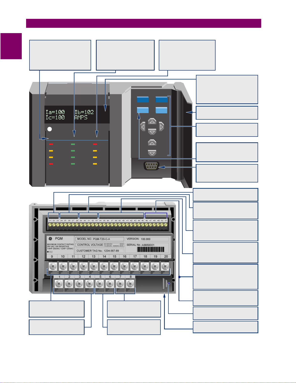
DISPLAY
40 character illuminated display for
programming, monitoring, status, fault
diagnosis, user programmable messages
and setpoints. Programmable auto scan
sequence for unattended operation.
DOOR:
Door covers keys and computer port
when not in use.
KEYPAD:
Rubber keypad is dust tight and
splash proof.
SETPOINT KEY:
Program all setpoints. Tamperproof
settings with passcode and access jumper
prevent unauthorized setpoint changes.
COMPUTER INTERFACE:
RS232 comm port for connecting to a PC.
Use for downloading setpoints, monitoring,
data collection, printing reports.
CT INPUTS:
3 isolated phase CT inputs
1 isolated neutral CT input
1 Amp or 5 Amp secondary
VT INPUTS:
0-600V, 3 wire or 4 wire voltage inputs.
Direct (up to 600V) or VT (>600V for
isolation) connections.
AC/DC CONTROL POWER
Universal control power
90-300 VDC
70-265 VAC
GROUND:
Separate safety and filter ground
All inputs meet C37.90 and IEC 801-2
EMI, SWC, RFI interference immunity.
Figure 1–1: PQM FEATURE HIGLIGHTS
ANALOG INPUT
Accept 4-20mA analog inputs for transducer
interface.
823756AK.CDR
ANALOG OUTPUTS
4 isolated 0-1mA or 4-20 mA outputs replace
8 transducers. Programmable including:
A, V, W, var, VA, Wh varh, PF, Hz
SWITCH INPUTS
A
Programmable for relay activation,
B
counters, logic, demand synchronization,
C
setpoint access, alarm position
}
D
4 OUTPUT RELAYS
ALARM
Programmable alarm conditions
AUX1
actuated by programmable
AUX2
setpoints, switch inputs, remote
}
AUX3
communication control.
COMMUNICATIONS
Dual RS485 comm ports Modbus protocol.
Continuous monitoring/control via
COM1
SCADA system rear (RS485).
COM2/3
Front (RS232) or rear (RS485) access
allows simultaneous communication
via a PC or for redundant comms.
PROGRAM UPDATING
Flash memory storage of firmware for field
updating via communications port. Enables
product updating on-site for latest features.
FUSE ACCESS
Control power fuse accessible under sliding
door.
COMPACT DESIGN
Panel mount replaces many discrete
components with one standard model.
®
823755AL.CDR
1-2 PQM Power Quality Meter GE Power Management
1 OVERVIEW 1.1 INTRODUCTION
1.1.3 APPLICATIONS
• Metering of distribution feeders, transformers, generators, capacitor banks, and motors
• Medium and low voltage three-phase systems
• Commercial, industrial, utility
• Flexible control for demand load shedding, power factor, etc.
• Power quality analysis
• System debugging
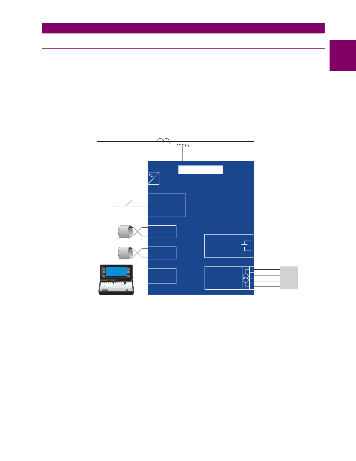
3 PHASE
3/4 WIRE BUS
0-600V DIRECT
>600V CT/VTs
AC/DC
CONTROL
POWER
-
CTs
VTs
PQM RELAY
4 SWITCH
INPUTS FOR
CONTROL
1
MAIN
SCADA
INSTRUMENTATION
ELECTRICAL
MAINTENANCE
COM 1
4
OUTPUT
COM 2
RS232
PORT
RELAYS
4
TRANSDUCER
OUTPUTS
Figure 1–2: SINGLE LINE DIAGRAM
ALARM
CONTROL
4-20mA
1
2
3
4
823768A2.CDR
PLC
or
RTU
GE Power Management PQM Power Quality Meter 1-3
1.2 STANDARD FEATURES 1 OVERVIEW
SIMULATION
ALARM
STATUS
SELF TEST
PROGRAM
TX2
TX1
COMMUNICATE
RX2
RX1
AUX2
ALARM
RELAYS
AUX3
AUX1
1.2 STANDARD FEATURES 1.2.1 METERING
1
I
,
I
,
I
,
I
,
V
,
V
,
V
,
V
,
V
,
V
True RMS monitoring of
a
b
c
n
an
bn
cn
ab
frequency, watts, vars, VA, Wh, varh, VAh, and demand read ings for A, W, vars, and VA. Maximum and minimum values of measured quantities are recorded and are date and time stamped.
A 40-character displ ay with brightness control is us ed for programming setpoin ts and monitoring values an d
status.
a) ALARMS
Alarm conditions can be set up for all meas ured quantities. The se include overcurren t, undercurrent, neutral
current, current u nbalance, vol tage unbalance , phase revers al, overfreque ncy, underfrequency, pow er factor,
switch inputs, etc. The alarm messages are displayed in a simple and easy to understand English format.
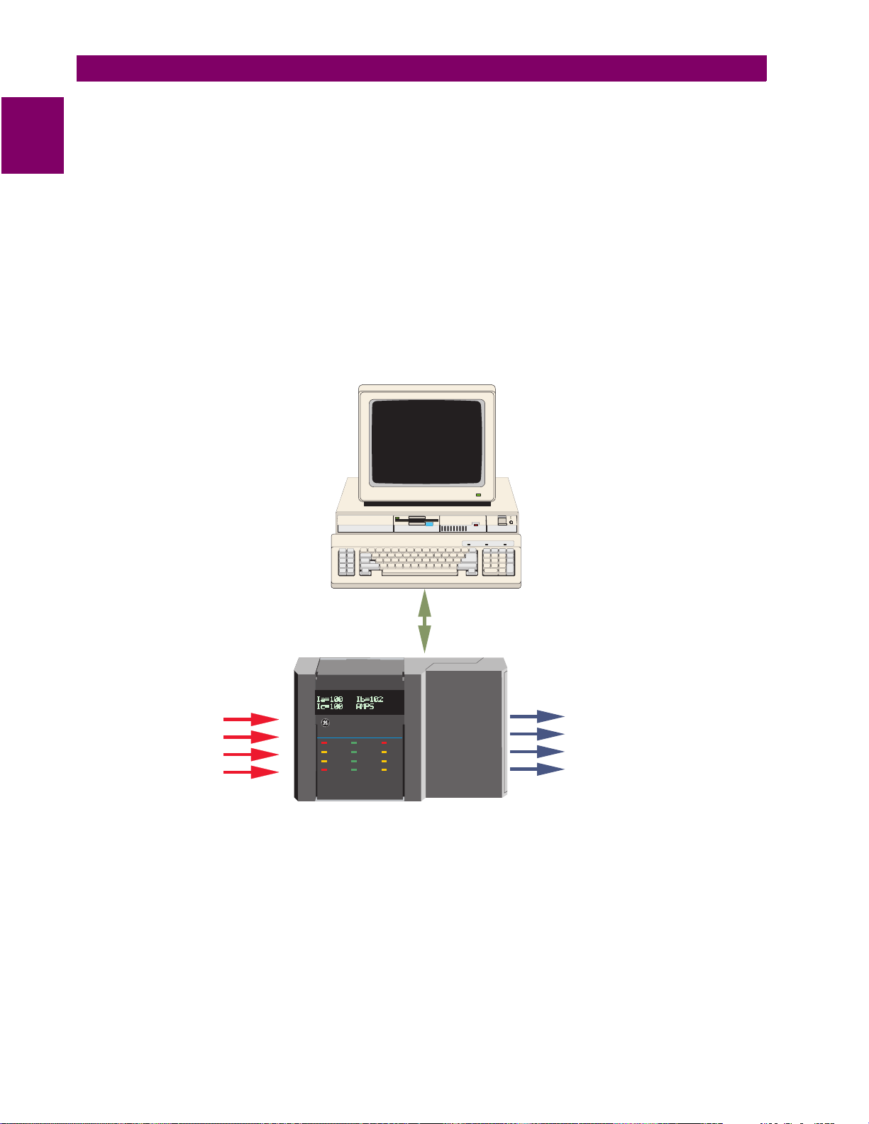
b) COMMUNICATION
The PQM is equipped wit h one standard RS485 port utilizing the Modbus or DNP 3.0 pr otocols. This can b e
used to integrate pr ocess, instrume ntation, and ele ctrical requiremen ts in a plant automation sy stem by connecting PQM meters toge ther to a DCS or SCADA system. A PC r unning PQMPC can change sy stem setpoints and monitor values, status, and alarms. Continuous monitoring minimizes process downtime by
immediately identifying potential problems due to faults or changes from growth.
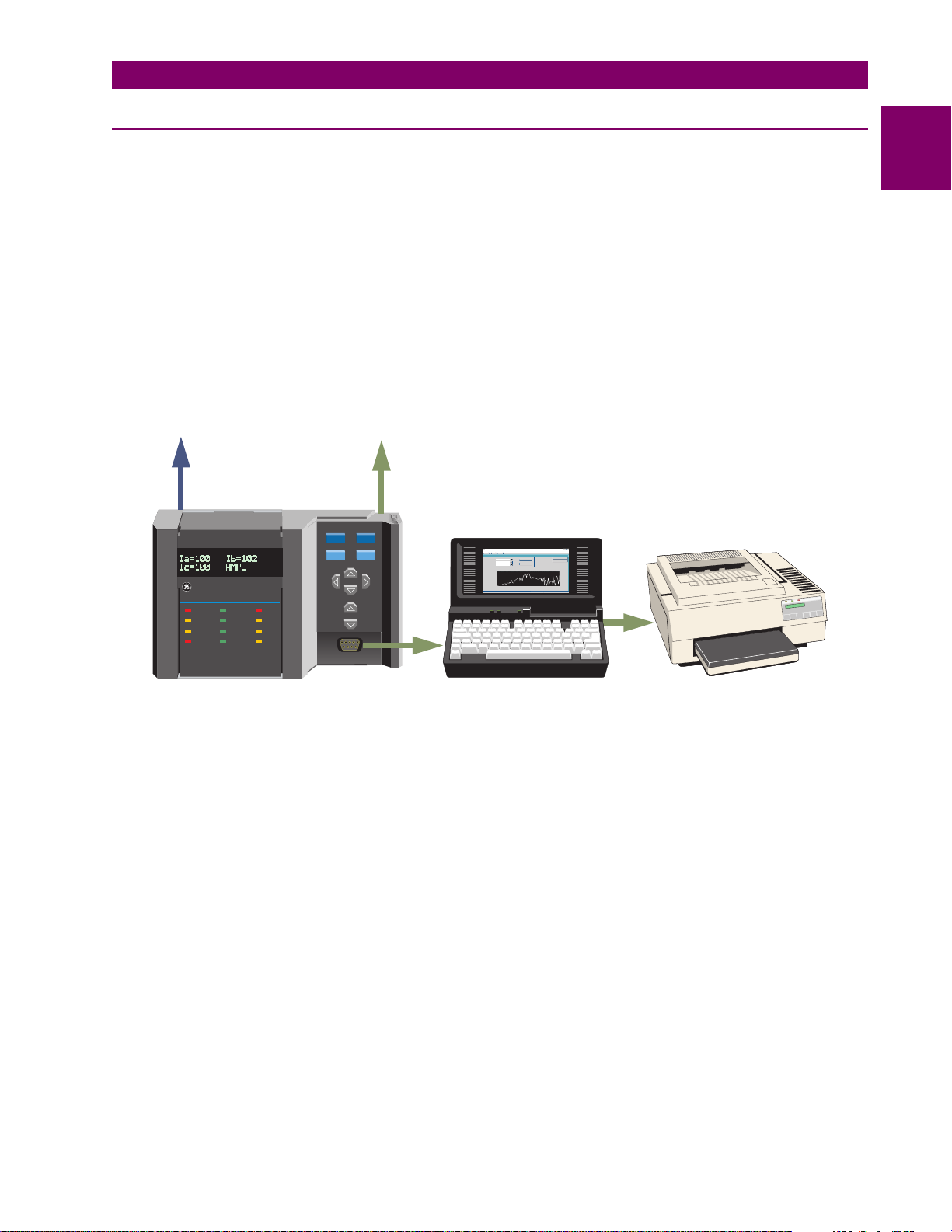
The PQM also includes a front RS232 port which may be employed to perform such tasks as:
• data monitoring
• problem diagnosis
, voltage/current unba lance, pow er factor, line
bc
ca
• viewing event records
• trending
• printing settings and/or actual values
• loading new firmware into the PQM
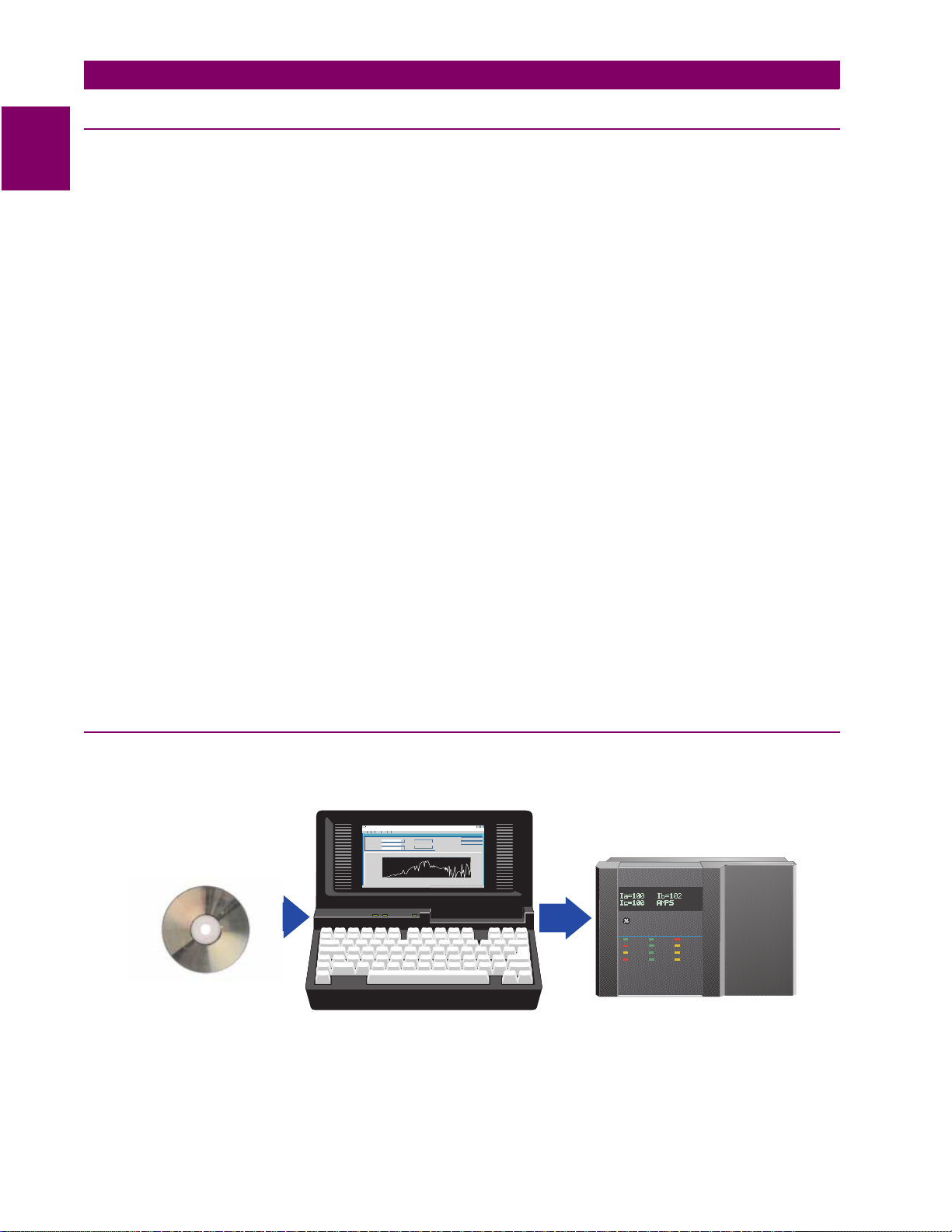
1.2.2 FUTURE EXPANSION
Flash memory is used to st ore firmw are with in the PQM. T his allo ws futur e produc t upgrad es to be loaded via
the serial port.
Product update
from GE Power
PQMWindowsApplication - PQM
Transfer new firmware
to the PQM
Management
CD-ROM
ForHelp,press F1
Seconds(ElapsedTime)
PQMPower Quality Meter
STATUS
ALARM
PROGRAM
SIMULATION
SELF TEST
COMMUNICATE
TX1
RX1
TX2
RX2
RELAYS
ALARM
AUX1
AUX2
AUX3
823774A5.CDR
Figure 1–3: DOWNLOADING PRODUCT ENHANCEMENTS VIA THE SERIAL PORT
PQM units can initially be used as standalone meters. Their open architecture allows connection to other Modbus compatible devi ces on the same com munication link. The se can be integrated in a complete plant-wid e
system for overall process monitoring and control.
1-4 PQM Power Quality Meter GE Power Management
1 OVERVIEW 1.2 STANDARD FEATURES
1.2.3 OPTIONAL FEATURES
a) TRANSDUCER OPTION
Four isolated 4 to 20 mA (or 0 to 1 mA depending on the installed option) analog outputs are provided that can
replace up to eight trans duc ers . T he o utpu ts c an be a ssig ned to any measured param eters for dire ct inte r fac e
to a PLC.
One 4 to 20 mA analog inp ut i s prov i ded t o ac ce pt a transducer output for di sp lay i ng in for ma tio n such as temperature or water level.
An additional re ar RS 485 co mmunication port is pr ov id ed for sim ultaneous monitor ing by pr oc ess , in strument,
electrical, or maintenance personnel.
Main plant
control/monitoring
communication
interface
Use 2nd/3rd comm ports for simultaneous
access by electrical, maintenance,
process, instrumentation personnel
for
•Data monitoring
•Problem diagnosis
•Event records
RS485 RS485
•Trending
•Report printing
Print reports
PQMPower Quality Meter
STATUS COMMUNICATE RELAYS
TX1
ALARM
PROGRAM
RX1
SIMULATION
TX2
SELFTEST
RX2
ALARM
AUX1
AUX2
AUX3
ACTUAL
SETPOINT
MESSAGE
VALUE
STORE
RESET
File
ForHelp,pressF1
PQMWindowsApplication- PQM
Actual
Help
Setpoint
Communication
Actual-ChartRecorder
OK
RUN
Cancel
PRINT
TrendingChart
Seconds(ElapsedTime)
1
RS232
Figure 1–4: ADDITIONAL COMMUNICATION PORT
823779A7.CDR
GE Power Management PQM Power Quality Meter 1-5
1.2 STANDARD FEATURES 1 OVERVIEW
b) CONTROL OPTION
An additional thre e dry-co ntact form “C ” output rela ys and fou r dry-cont act switch inputs ar e provided. T hese
1
additional relays can be combined with setpoints and inputs/outputs for control applications. Possibilities
include:
• undercurrent alarm warnings for pump protection
• over/undervoltage for gener ato rs
• unbalance alarm warnings to protect rotating machines
• dual level power factor for capacitor bank switching
• underfrequency/demand output for load shedding resulting in power cost savings
• kWh, kvarh and kVAh pulse output for PLC interface
• Pulse input for totalizing quantities such as kWh, kvarh, kVAh, etc.
DCS
RS485
MODBUS
PQM
4
SWITCH
INPUTS
PQMPower Quality Meter
STATUS COMMUNICATE RELAYS
ALARM
PROGRAM
SIMULATION
SELFTEST
Figure 1–5: SWITCH INPUTS AND OUTPUTS RELAYS
ALARM
TX1
AUX1
RX1
AUX2
TX2
AUX3
RX2
RELAYS
4
ALARM
AUX 1
AUX 2
AUX 3
823775A6.DWG
1-6 PQM Power Quality Meter GE Power Management
1 OVERVIEW 1.2 STANDARD FEATURES
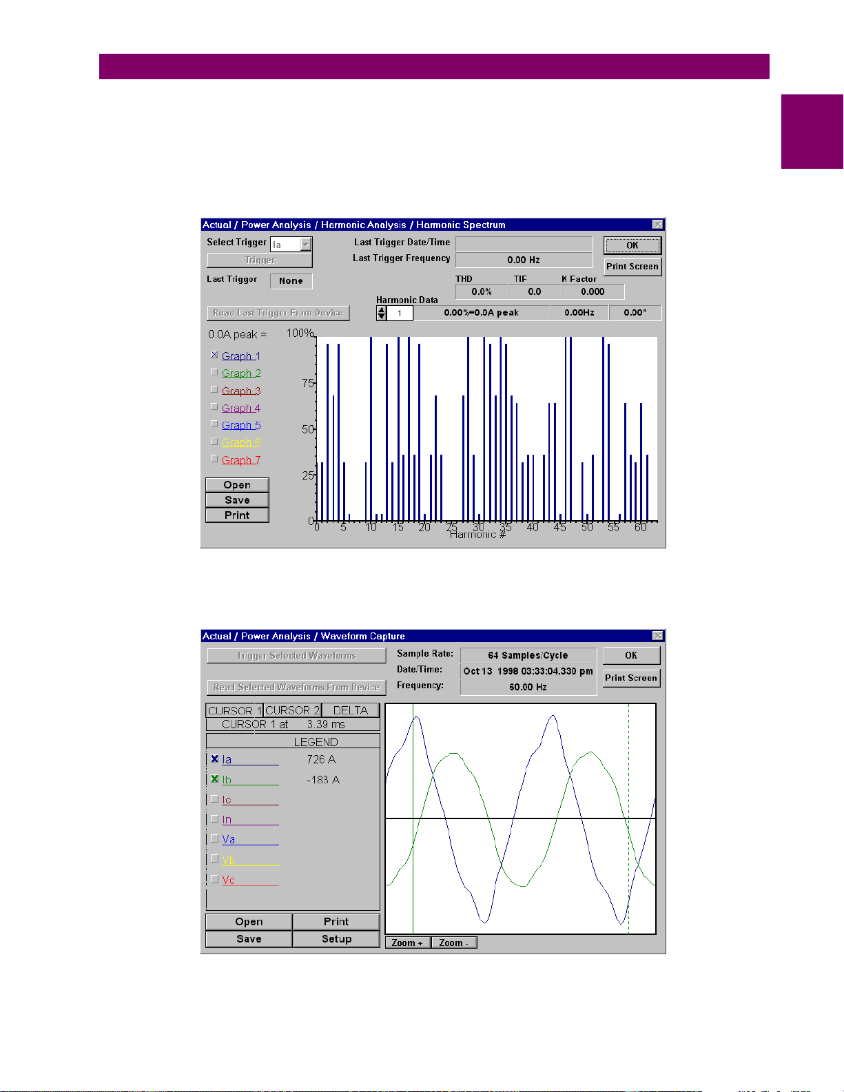
c) POWER ANALYSIS OPTION
Non-linear loads (such as variable speed drives, computers, and electronic ballasts) can cause unwanted harmonics that may lead to nuisance breaker tripping, telephone interference, and transformer, capacitor or motor
overheating. For fault dia gnostics such as detecting undersized ne utral wiring, assessing the need for harmonic rated transformers, or judging the effectiveness of harmonic filters, details of the harmonic spectrum are
useful and available with the power analysis option.
1
Figure 1–6: HARMONIC SPECTRUM
Voltage and current waveforms can be captured and displa yed on a PC with PQMPC or t hird party softwa re.
Distorted peaks or notches from SCR switching provide clues for taking corrective action.
Figure 1–7: CAPTURED WAVEFORM
GE Power Management PQM Power Quality Meter 1-7
1.2 STANDARD FEATURES 1 OVERVIEW
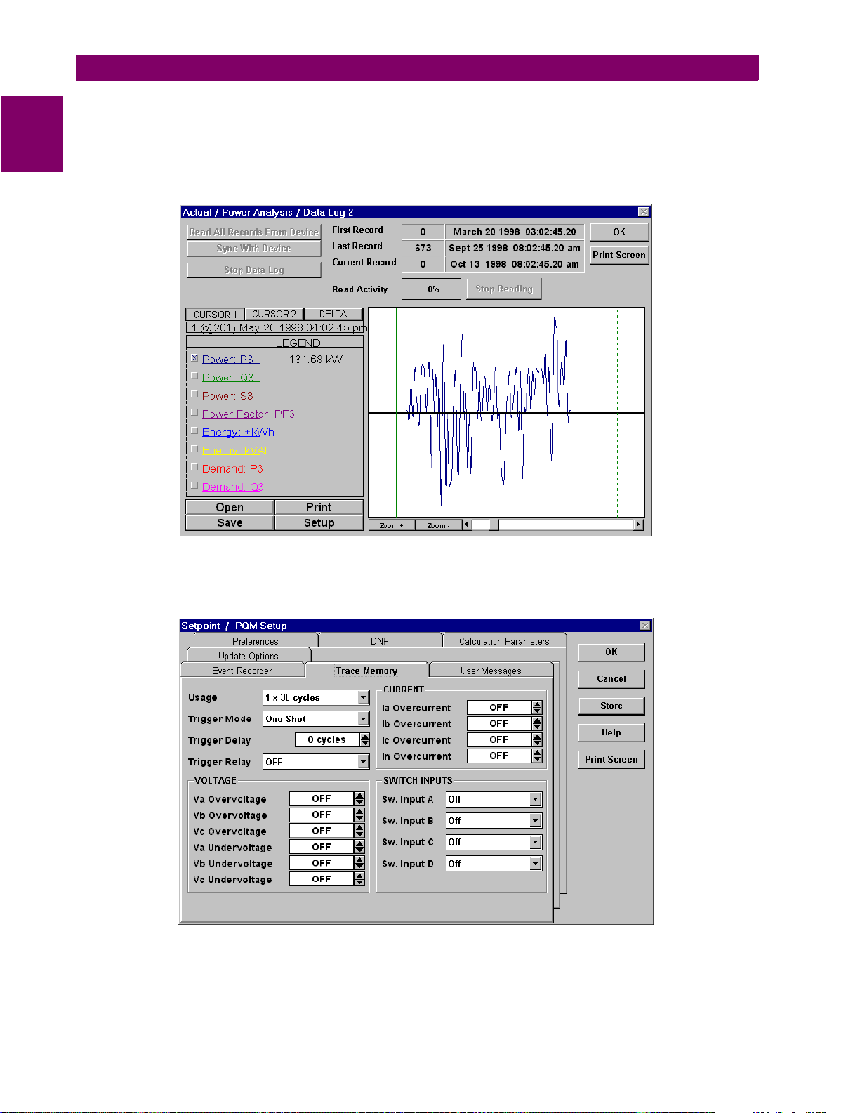
Alarms, setpoint triggers, and input and output events can be stored in a 40-event record and time/date
stamped by the inter nal clock . This is usefu l for diag nosing prob lems and s ystem acti vity. The event record is
1
available through serial communication. Minimum and maximum value s are also c ontinuously updated and
time/date stamped.
Routine event logs of all measured quantities can be created, saved to a file, and/or printed.
Figure 1–8: DATA LOGGER
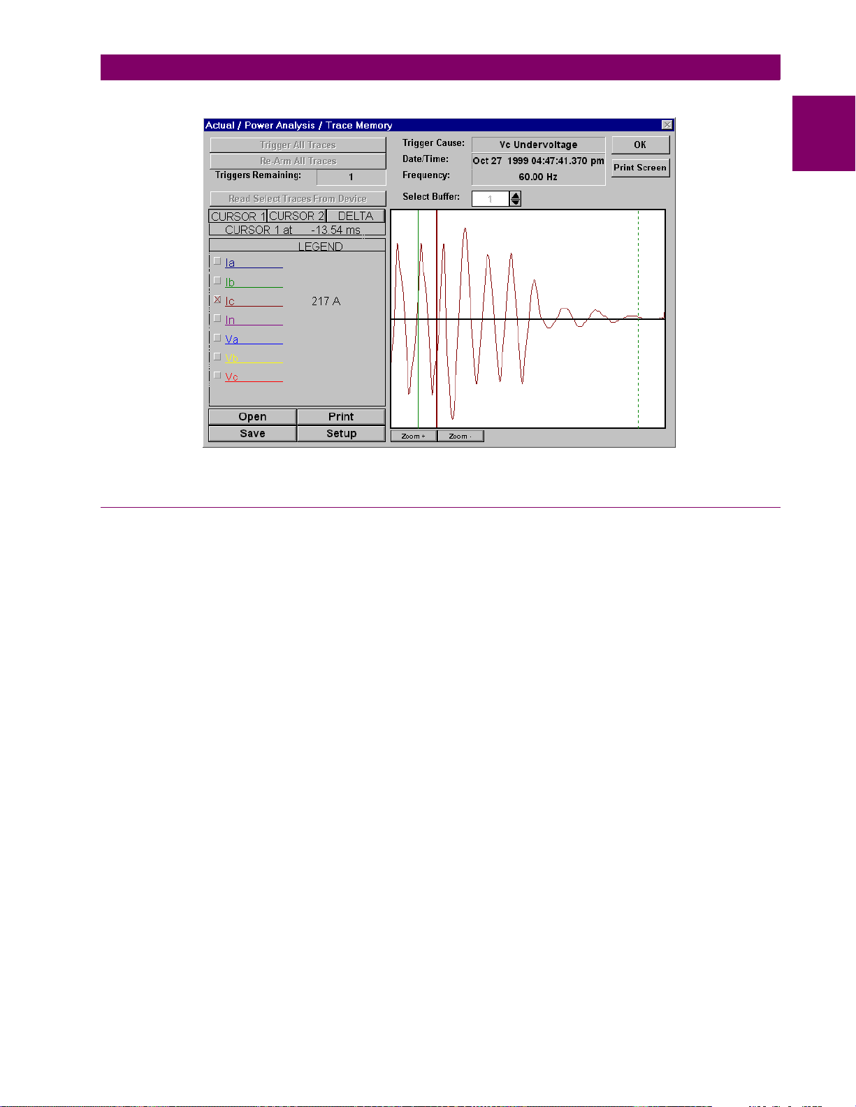
The power analysis option also provides a Trace Memory feature. This feature can be used to record specified
parameters based on the user defined triggers.
Figure 1–9: TRACE MEMORY TRIGGERS
1-8 PQM Power Quality Meter GE Power Management
1 OVERVIEW 1.2 STANDARD FEATURES
Figure 1–10: TRACE MEMORY CAPTURE
1
1.2.4 PQMPC SOFTWARE
All data continuously gathered by the PQM can be transferred to a third party software program for display,
control, or analys is t hr oug h th e c omm uni c atio ns in ter face. The PQMPC softwa r e ma ke s thi s d ata im med iate ly
useful and assists in pr ogramming the PQM. S ome of the task s that can b e executed us ing the PQMP C software package are:
• read metered data
• monitor system status
• change PQM setpoints on-line
• save setpoints to a file and download into any PQM
• capture and display voltage and current wave shapes for analysis
• record demand profiles for various measured quantities
• troubleshoot communication problems with a built in communications debugging tool
• print all graphs, charts, setpoints, and actual data
The PQMPC software is fully described in Chapter 6: SOFTWARE.
GE Power Management PQM Power Quality Meter 1-9

1.2 STANDARD FEATURES 1 OVERVIEW
1.2.5 ORDER CODES
1
The order code for all options is:
Table 1–1: ORDER CODES
S S S
|
|
T20
Basic Unit
Transducer
Option
PQM
PQM
T1
Control
Option
Power Analysis
Option
Modifications (consult the factory for any additional modification costs):
• MOD 500: Portable test/carrying case
• MOD 501: 20 to 60 V DC / 20 to 48 V AC control power
• MOD 502: Tropicalization
• MOD 504: Removable terminal blocks
• MOD 505: PQM Remote: Base Unit with Detachable Faceplate
PQM-T20-C-A
|
|
|
|
|
|
C
Basic Unit with display, all current/voltage/power measurements, 1 RS485
|
communication port, 1 RS232 communication port
|
4 isolated analog outputs, 0-20 mA and 4-20 mA assignable to all measured
|
parameters, 4-20 mA analog input, 2nd RS485 communication port
|
4 isolated analog outputs, 0-1 mA assignable to all measured parameters, 4-
|
20 mA analog input, 2nd RS485 communication port
|
3 additional programmable output relays (for a total of 4), 4 programmable
|
switch inputs
|
Harmonic analysis, triggered trace memory, waveform capture, event
A
recorder, data logger
• MOD 506: 4 Step Capacitor Bank Switching
• MOD 507: –40°C to +60°C Extended Temperature Operation
• MOD 508: 269/565 Communication Protocol
• MOD 513: Class 1, Division 2 Operation
• MOD 516: PQM Remote: Base Unit only
• MOD 517: PQM Remote: Detachable Faceplate only
Accessories (consult the factory for any additional accessory costs):
• PQMPC Windows software (free upon request)
• RS232 to RS485 converter (required to connect a PC to the PQM RS485 ports)
• 2.25” collar for limited depth mounting
• RS485 terminating network
• PQM mounting plate to replace MTM Plus
Control Power:
• 90 to 300 V DC / 70 to 265 V AC standard
• 20 to 60 V DC / 20 to 48 V AC (MOD 501)
1-10 PQM Power Quality Meter GE Power Management

1 OVERVIEW 1.3 SPECIFICATIONS
1.3 SPECIFICATIONS 1.3.1 PQM SPECIFICATIONS
CURRENT INPUTS
CONVERSION: true rms, 64 samples/cycle
CT INPUT: 1 A and 5 A secondary
BURDEN: 0.2 VA
OVERLOAD: 20 × CT for 1 sec.
100 × CT for 0.2 sec.
RANGE: 1 to 150% of CT primary
FREQUENCY: up to 32nd harmonic
ACCURACY: ±0.2% of full scale
VOLTAGE INPUTS
CONVERSION: true rms, 64 samples/cycle
VT PRI/SEC: direct or 120 to 72000:69 to 240
BURDEN: 2.2 MΩ
INPUT RANGE: 20 to 600 V AC
FULL SCALE: 150/600 V AC autoscaled
FREQUENCY: up to 32
ACCURACY: ±0.2% of full scale
nd
harmonic
TRACE MEMORY TRIGGER
INPUT 1 cycle of data (current, voltage)
TIME DELAY: 0 to 30 cycles
SAMPLING MODES
METERED
VALUES
TRACE
MEMORY
HARMONIC
SPECTRUM
SAMPLES
/CYCLE
64 ALL 2
16 ALL continuous
256 1 1
INPUTS SAMPLED
AT A TIME
DURATION
(cycles)
SWITCH INPUTS
TYPE: dry contacts
RESISTANCE: 1000 Ω max ON resistance
OUTPUT: 24 V DC @ 2 mA (pulsed)
DURATION: 100 ms minimum
ANALOG OUTPUTS
OUTPUT
0-1 mA
(T1 Option)
MAX LOAD
MAX OUTPUT 1.1 mA 21 mA
ACCURACY: ±1% of full scale reading
ISOLATION: 50 V isolated, active source
Ω
2400
4-20 mA
(T20 Option)
Ω
600
ANALOG INPUT
RANGE: 4 to 20 mA
ACCURACY: ±1% of full scale reading
INTERNAL BURDEN
RESISTANCE: 250 Ω
OUTPUT RELAYS
VOLTAGE MAKE/CARRY BREAK
continuous 0.1 sec.
RESISTIVE 30 VDC 5A 30A 5A
125 VDC 5A 30A 0.5A
250 VDC 5A 30A 0.3A
INDUCTIVE
(L/R=7ms)
RESISTIVE 120 VAC 5A 30A 5A
INDUCTIVE
PF=0.4
CONFIGURATION: Form C NO/NC
CONTACT MATERIAL:Silver Alloy
30 VDC 5A 30A 5A
125 VDC 5A 30A 0.25A
250 VDC 5A 30A 0.15A
250 VAC 5A 30A 5A
120 VAC 5A 30A 5A
250 VAC 5A 30A 5A
1
GE Power Management PQM Power Quality Meter 1-11

1.3 SPECIFICATIONS 1 OVERVIEW
MEASURED VALUES
1
PARAMETER ACCURACY
(% of full scale)
VOLTAGE ±0.2% 20% to 100% of VT
CURRENT ±0.2% 1% to 150% of CT
V UNBALANCE ±1% 0 to 100%
I UNBALANCE ±1% 0 to 100%
kW see Accuracy Details 0 to ±999,999.99 kW
kvar see Accuracy Details 0 to ±999,999.99 kvar
kVA see Accuracy Details 0 to 999,999.99 kVA
kWh see Accuracy Detail s 2
kvarh see Accuracy Detail s 2
kVAh see Accuracy Details 2
PF ±1.0% ± 0.00 to 1.00
FREQUENCY ±0.02Hz 20.00 to 70.00 Hz
kW DEMAND ±0.4% 0 t o ±999 999.99 kW
kvar DEMAND ±0.4% 0 to ±999 999.99 kvar
kVA DEMAND ±0.4% 0 to 999999.99 kVA
AMP DEMAND ±0.2% 0 to 7500 A
AMPS THD ±2.0% 0.0 to 100.0%
VOLTS THD ±2.0% 0.0 to 100.0%
CREST FACTOR ±0.4% 1 to 9.99
RANGE
32
kWh
32
kvarh
32
kVAh
UNDERVOLTAGE MONITORING
REQ’D VOLTAGE: > 20 V applied in all phases
PICKUP: 0.50 to 0.99 in steps of 0.01 × VT
DROPOUT: 103% of pickup
TIME DELAY: 0.5 to 600.0 in steps of 0.5 sec.
PHASES: Any 1 / Any 2 / All 3 (prog rammable)
have to be ≤ pickup to operate
ACCURACY: Per voltage input
TIMING ACCURACY: –0 / +1 sec.
OVERVOLTAGE MONITORING
PICKUP: 1.01 to 1.25 in steps of 0.01 × VT
DROPOUT: 97% of pickup
TIME DELAY: 0.5 to 600.0 in steps of 0.5 sec.
PHASES: Any 1 / Any 2 / All 3 (prog rammable)
must be ≥ pickup to operate
ACCURACY: Per voltage input
TIMING ACCURACY: –0 / +1 sec.
UNDERFREQUENCY MONITORING
REQ’D VOLTAGE: > 30 V applied in phase A
PICKUP: 20.00 to 70.00 in steps of 0.01 Hz
DROPOUT: Pickup + 0.03 Hz
TIME DELAY: 0.1 to 10.0 in steps of 0.1 sec.
ACCURACY: 0.02 Hz
TIMING ACCURACY: ±3 cycles
OVERFREQUENCY MONITORING
REQ’D VOLTAGE: > 30 V applied in phase A
PICKUP: 20.00 to 70.00 in steps of 0.01 Hz
DROPOUT: Pickup – 0.03 Hz
TIME DELAY: 0.0 to 10.0 in steps of 0.1 sec.
ACCURACY: 0.02 Hz
TIMING ACCURACY: ±3 cycles
POWER FACTOR MONITORING
REQ’D VOLTAGE: > 20 V applied in phase A
PICKUP: 0.50 lag to 0.50 lead step 0.01
DROPOUT: 0.50 lag to 0.50 lead step 0.01
TIME DELAY: 0.5 to 600.0 in steps of 0.5 sec.
TIMING ACCURACY: –0 / +1 sec.
DEMAND MONITORING
MEASURED VALUES:Phase A/B/C/N Current (A)
3φ Real Power (kW)
3φ Reactive Power (kvar)
3φ Apparent Power (kVA)
MEASUREMENT TYPE:
Thermal Exponential 90% response time
(programmable): 5 to 60 min. step 1
Block interval: (programmable): 5 to 60 min. step 1
Rolling Demand
time interval: (programmable): 5 to 60 min. step 1
PICKUP: A: 10 to 7500 in steps of 1000
kW: 0.1 to 6500.0 in steps of 0.1
kvar: 0.1 to 6500.0 in steps of 0.1
kVA: 0.1 to 6500.0 in steps of 0.1
PULSE OUTPUT
PARAMETERS: +kWh, –kWh, +kvarh, –kvarh, kVAh
INTERVAL: 1 to 65000 in steps of 1
PULSE WIDTH: 100 to 2000 ms in steps of 10 ms
MIN. PULSE INTERVAL: 500 ms
ACCURACY: ±10 ms
PULSE INPUT
MAX INPUTS: 4
MIN PULSE WIDTH: 150 ms
MIN OFF TIME: 200 ms
1-12 PQM Power Quality Meter GE Power Management

1 OVERVIEW 1.3 SPECIFICATIONS
WARNING
COMMUNICATIONS
COM1/COM2 TYPE: RS485 2-wire, half duplex, isolated
COM3 TYPE: RS232 9-pin
BAUD RATE: 1200 to 19200
PROTOCOLS: Modbus
FUNCTIONS: Read/write setpoints
Read actua l values
Execute commands
Read Device Status
Loopback Test
®
RTU; DNP 3.0
CLOCK
ACCURACY: ±1 minute / 30 days at 25°C ± 5°C
RESOLUTION: 1 sec.
CONTROL POWER
INPUT: 90 to 300 V DC or
70 to 265 V AC, 50/60 Hz
POWER: nominal 10 VA
maximum 20 VA
HOLDUP: 100 ms typical
(@ 120 V AC / 125 V DC)
IT IS RECOMMENDED THAT THE PQM BE
POWERED UP AT LEAST ONCE PER YEAR
TO AVOID DETERIORATION OF THE ELECTROLYTIC CAPACITORS IN THE POWER
SUPPLY.
TYPE TESTS
DIELECTRIC STRENGTH:
2.0 kV for 1 minute to relays, CTs,
VTs, power supply
INSULATION RESISTANCE: IEC255-5, 500 V DC
TRANSIENTS: ANSI C37.90.1 Oscillatory
2.5 kV/1 MHz
ANSI C37.90.1 Fast Rise 5 kV/10 ns
Ontario Hydro A-28M-82
IEC255-4 Impulse/High Frequency
Disturbance Class III Level
IMPULSE TEST: IEC 255-5 0.5 Joule 5kV
RFI: 50 MHz/15 W Transmitter
EMI: C37.90.2 Electromagnetic Interfer-
ence @ 150 MHz and 450 MHz,
10V/m
STATIC: IEC 801-2 Static Discharge
HUMIDITY: 95% non-condensing
TEMPERATURE: –10°C to +60°C ambient
ENVIRONMENT: IEC 68-2-38 Temperature/Humidity
Cycle
PACKAGING
SHIPPING BOX: 8½" × 6" × 6" (L×H×D)
21.5cm × 15.2cm × 15.2 cm
(L×H×D)
SHIP WEIGHT: 5 lbs/2.3 kg
1
CERTIFICATION
ISO: Manufactured under an ISO9001
registered program
UL: recognized under E83849
CSA: recognized under LR41286
CE: Conforms to EN 55011 / CISPR 11,
EN50082-2, IEC 947-1, IEC 1010-1
GE Power Management PQM Power Quality Meter 1-13
1.3 SPECIFICATIONS 1 OVERVIEW
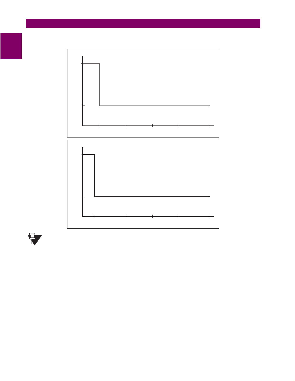
PQM POWER AND ENERGY ACCURACY
Accuracy is a per curves ±1 digit on PQM display.
1
0.5
% Error of Reading
0.2
PQM Power Accuracy at P.F. > 0.95
(kW/kVAR/kVA)
NOTE
120
1.0
% Error of Reading
0.4
15
50 75 100 150
% Load
PQM Energy Accuracy at P.F. > 0.95
(±kWh / ±kVARh / kVAh)
50 75 100 150
% Load
SPECIFICATIONS ARE SUBJECT TO CHANGE WITHOUT NOTICE.
1-14 PQM Power Quality Meter GE Power Management
2 INSTALLATION 2.1 PHYSICAL
2 INSTALLATION 2.1 PHYSICAL 2.1.1 MOUNTING
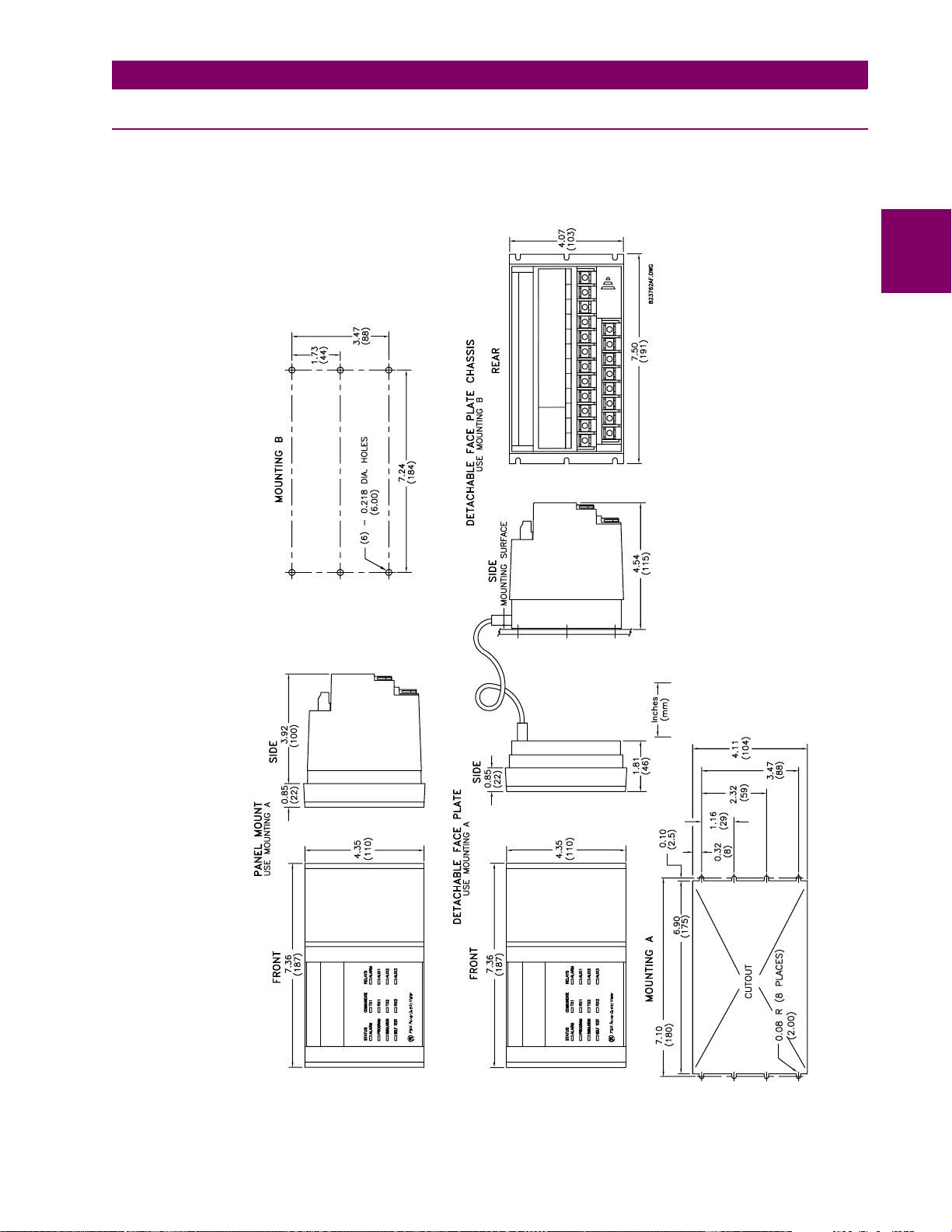
Physical dimensions and required cutout dimensions for the PQM are shown below. Once the cutout and
mounting holes are made in the panel, use the eight #6 self-tapping screws provided to secure the PQM.
Mount the unit on a panel or switchgear door to allow operator access to the keypad and indicators.
2
Figure 2–1: PHYSICAL DIMENSIONS
GE Power Management PQM Power Quality Meter 2-1
2.1 PHYSICAL 2 INSTALLATION
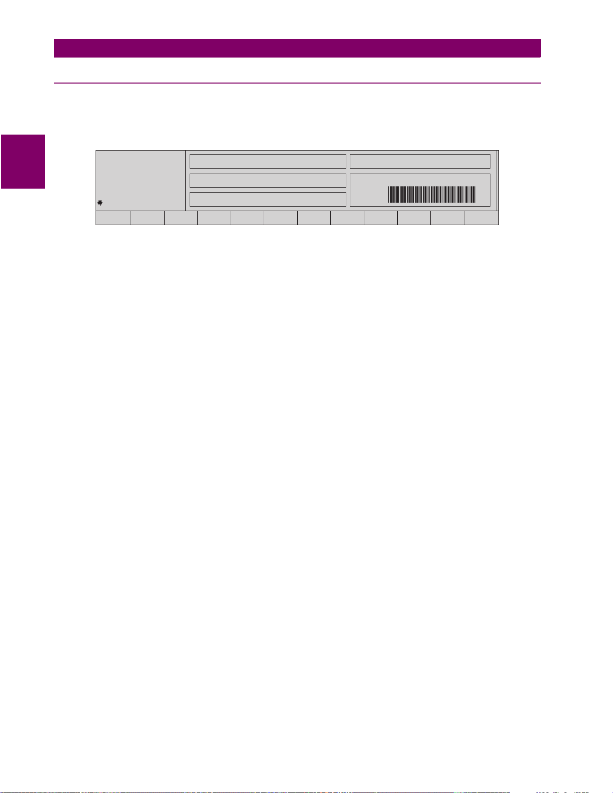
2.1.2 PRODUCT IDENTIFICATION
Product attributes vary according to the configuration and options selected on the customer order. Before
applying power to the PQM, examine the label on the back and ensure the correct options are installed.
The following section explains the information included on the label shown below:
2
PQM
g
MAXIMUM CONTACT RATING
250 VAC 10A RESISTIVE
1/4HP 250VAC 1/2HP 125VAC
MADE IN
CANADA
9
10
MODEL NO.:
CONTROL VOLTAGE: SERIAL No.:
CUSTOMER TAG No.: 1234-567-89
11
PQM-T20-C-A
90-300VDC 20VA
70-265VAC 50/60HZ 20VA
141312
15
VERSION:
16
17
340.000
C6560001
18
19
20
Figure 2–2: PRODUCT LABEL
MODEL NO
1.
: Shows the PQM con figuration. The m odel number for a basic panel mount PQM is “PQ M”.
The model number for a basic chassis mount PQM is “PQM\ND”. T20, C, and A appear in the model number only if the Transducer, Control, or Power Analysis options are installed.
SUPPLY VOLTAGE
2.
: Indicates the power supply input configuration installed in the PQM. The PQM shown
in this example c an ac cept a ny AC 50/60H z vo ltage f rom 7 0 to 26 5 V A C o r DC vol tage f rom 9 0 to 30 0 V
DC.
TAG#
3.
4.
: An optional identification number specified by the customer.
MOD#
: Used if uniqu e features have be en installed for special customer orders. This num ber should be
available when contacting GE Power Management for technical support.
VERSION
5.
: An internal GE Power Man agement number that should be av ailable when contacting us for
technical support.
SERIAL NO
6.
: Indicates the serial number for the PQM in numeric and barcode formats that should be avail-
able when contacting GE Power Management for technical support.
2-2 PQM Power Quality Meter GE Power Management

2 INSTALLATION 2.1 PHYSICAL
2.1.3 REVISION HISTORY
The following table shows the PQM revision h istory. Each revision of t he instr uction man ual cor responds to a
particular firmware revision. The manual revision is located on the title page as part of the manual part number
(the format is 1665-0003-
A4 PRODUCT INFO \ SOFTWARE VERSIONS \ MAIN PROGRAM VERSION
to the
revision
). The firmware revision is loa ded in the PQ M and ca n be vi ewed by sc r oll in g
actual value message.
When using the instruction manual to determine PQM features and settings, ensure that the instruction manual
revision corresponds to the firmware revision installed in the PQM using the table below.
Table 2–1: REVISION HISTORY TABLE
INSTRUCTION
MANUAL P/N
1665-0003-C1 0.10
1665-0003-C2 0.20
1665-0003-C3 1.00
1665-0003-C4 1.10
1665-0003-C5 1.20
1665-0003-C6 1.21, 1.22
1665-0003-C7 2.00
1665-0003-C8 2.01
1665-0003-C9 2.02
1665-0003-CA 3.00
1665-0003-CB 3.01
1665-0003-CC 3.10
1665-0003-CD 3.13
1665-0003-CE 3.2x, 3.3x
1665-0003-CF 3.4x
1665-0003-CG 3.5x
MAIN PROGRAM
VERSION
2
GE Power Management PQM Power Quality Meter 2-3

2.2 ELECTRICAL 2 INSTALLATION
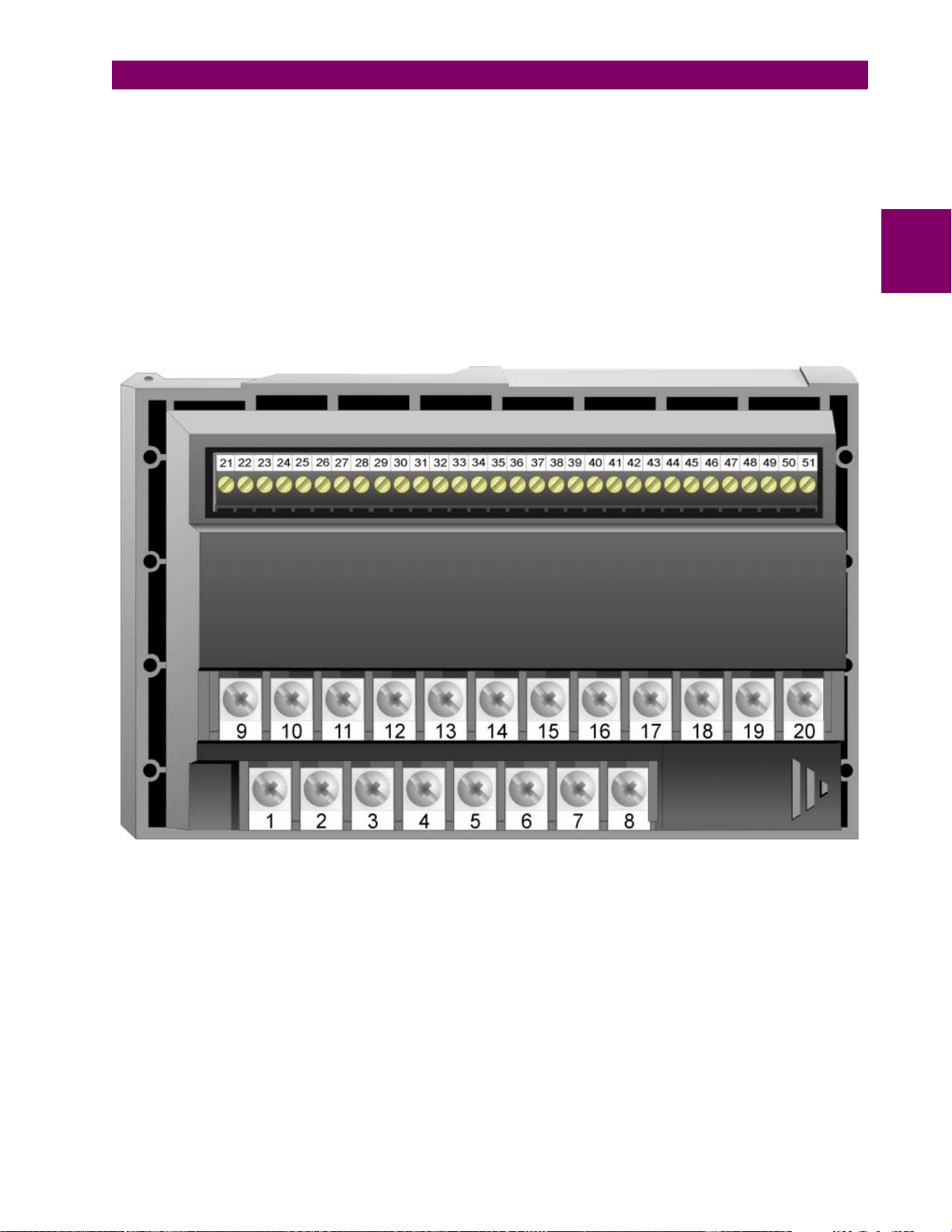
2.2 ELECTRICAL 2.2.1 EXTERNAL CONNECTIONS
Signal wiring is to Terminals 21 to 51. These termin al s a ccom modate wires sizes up to 1 2 g auge.
that the maximum torque that can be applied to terminals 21 to 51 is 0.5 Nm (or 4.4 in ·lb.)
. CT, VT, and control
power connections are made using Terminals 1 to 20. These #8 screw ring terminals accept wire sizes as large
as 8 gauge. Consult the wiring diagrams for suggested wiring. A minimal configuration includes connections for
control power, phase CTs/VT s, and the alarm relay; other features can be wired as required. Considerations for
2
wiring each feature are given in the sections that follow.
Table 2–2: PQM EXTERNAL CONNECTIONS
VT / CONTROL POWER ROW CT ROW SIGNAL UPPER ROW
1 V1 Voltage input 9 Phase A CT 5A 21 Analog shield
2 V2 Voltage input 10 Phase A CT 1A 22 Analog in –
3 V3 Voltage input 11 Phase A CT COM 23 Analog in +
4 Vn Voltage input 12 Phase B CT 5A 24 Analog out com
5 Filter ground 13 Phase B CT 1A 25 Analog out 4+
6 Safety ground 14 Phase B CT COM 26 Analog out 3+
7 Control neutral (–) 15 Phase C CT 5A 27 Analog out 2+
8 Control live (+) 16 Phase C CT 1A 28 Analog out 1+
17 Phase C CT COM 29 Switch 4 input
18 Neutral CT 5A 30 Switch 3 input
19 Neutral CT 1A 31 Switch 2 input
20 Neutral CT COM 32 Switch 1 input
33 +24 V DC switch com
34 Aux3 relay NC
35 Aux3 relay COM
36 Aux3 relay NO
37 Aux2 relay NC
38 Aux2 relay COM
39 Aux2 relay NO
40 Aux1 relay NC
41 Aux1 relay COM
42 Aux1 relay NO
43 Alarm relay NC
44 Alarm relay COM
45 Alarm relay NO
46 Comm 1 COM
47 Comm 1 –
48 Comm 1 +
49 Comm 2 COM
50 Comm 2 –
51 Comm 2 +
Please note
2-4 PQM Power Quality Meter GE Power Management
2 INSTALLATION 2.2 ELECTRICAL
2
Figure 2–3: REAR TERMINALS
GE Power Management PQM Power Quality Meter 2-5
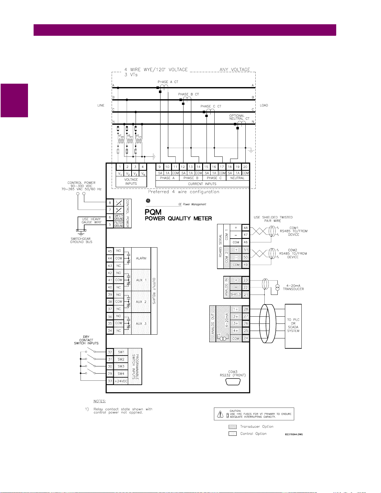
2.2 ELECTRICAL 2 INSTALLATION
This wiring diagram sho ws the typical 4-wire wye connecti on which will cover any voltage range. Select the
S2 SYSTEM SETUP \ CURRENT/VOLTAGE CONFIGURATION \ VT WIRING: 4 WIRE WYE (3 VTs)
setpoint.
2
Figure 2–4: WIRING DIAGRAM 4-WIRE WYE (3 VTs)
2-6 PQM Power Quality Meter GE Power Management
 Loading...