

GE PQMII Instruction Manual
Digital Energy
Multilin
Software Revision: 2.2x
Manual P/N: 1601-0118-AD
Manual Order Code: GEK-106435M
Copyright © 2010 GE Multilin
PQMII Power Quality Meter
Instruction Manual
GE Multilin
215 Anderson Avenue, Markham, Ontario
Canada L6E 1B3
Tel: (905) 294-6222 Fax: (905) 201-2098
Internet:
http://www.GEmultilin.com
*1601-0118-AD*
GE Multilin's Quality Management
System is registered to ISO9001:2000
QMI # 005094
UL # A3775

© 2010 GE Multilin Incorporated. All rights reserved.
GE Multilin PQMII Power Quality Meter instruction manual for revision 2.2x.
PQMII Power Quality Meter, is a registered trademark of GE Multilin Inc.
The contents of this manual are the property of GE Multilin Inc. This documentation is
furnished on license and may not be reproduced in whole or in part without the permission
of GE Multilin. The content of this manual is for informational use only and is subject to
change without notice.
Part numbers contained in this manual are subject to change without notice, and should
therefore be verified by GE Multilin before ordering.
Part number: 1601-0118-AD (May 2010)

TABLE OF CONTENTS
Table of Contents
1: OVERVIEW INTRODUCTION TO THE PQMII ................................................................................................... 1-1
D
ESCRIPTION ........................................................................................................................ 1-1
F
EATURE HIGHLIGHTS ......................................................................................................... 1-2
A
PPLICATIONS OF THE PQMII ........................................................................................... 1-2
STANDARD FEATURES ................................................................................................................... 1-5
M
ETERING ............................................................................................................................. 1-5
A
LARMS ................................................................................................................................. 1-5
C
OMMUNICATIONS .............................................................................................................. 1-5
F
UTURE EXPANSION ............................................................................................................ 1-5
O
PEN ARCHITECTURE ......................................................................................................... 1-6
OPTIONAL FEATURES ..................................................................................................................... 1-7
T
RANSDUCER INPUT/OUTPUTS ......................................................................................... 1-7
C
ONTROL OPTION ............................................................................................................... 1-7
P
OWER ANALYSIS OPTION .................................................................................................1-8
ENERVISTA PQMII SETUP SOFTWARE .....................................................................................1-12
O
VERVIEW ............................................................................................................................ 1-12
ORDER CODES ................................................................................................................................... 1-13
O
RDER CODE TABLE ........................................................................................................... 1-13
M
ODIFICATIONS ................................................................................................................... 1-13
A
CCESSORIES ....................................................................................................................... 1-13
C
ONTROL POWER ................................................................................................................ 1-13
SPECIFICATIONS ............................................................................................................................... 1-14
I
NPUTS/OUTPUTS ................................................................................................................ 1-14
T
RACE MEMORY TRIGGER .................................................................................................. 1-15
S
AMPLING MODES .............................................................................................................. 1-15
O
UTPUT RELAYS .................................................................................................................. 1-15
M
ETERING ............................................................................................................................. 1-16
M
ONITORING ........................................................................................................................ 1-16
S
YSTEM ................................................................................................................................. 1-18
T
ESTING AND APPROVALS .................................................................................................. 1-18
P
HYSICAL .............................................................................................................................. 1-20
2: INSTALLATION PHYSICAL CONFIGURATION ........................................................................................................ 2-1
M
OUNTING ........................................................................................................................... 2-1
P
RODUCT IDENTIFICATION .................................................................................................. 2-2
R
EVISION HISTORY .............................................................................................................. 2-2
ELECTRICAL CONFIGURATION ................................................................................................... 2-3
E
XTERNAL CONNECTIONS ..................................................................................................2-3
W
IRING DIAGRAMS ............................................................................................................. 2-5
3-
WIRE SYSTEM USING TWO CTS .................................................................................... 2-12
C
ONTROL POWER ................................................................................................................ 2-13
VT I
NPUTS ............................................................................................................................ 2-13
CT I
NPUTS ............................................................................................................................ 2-13
O
UTPUT RELAYS .................................................................................................................. 2-14
S
WITCH INPUTS (OPTIONAL) .............................................................................................. 2-14
A
NALOG OUTPUTS (OPTIONAL) ......................................................................................... 2-16
A
NALOG INPUT (OPTIONAL) ............................................................................................... 2-17
PQMII POWER QUALITY METER – INSTRUCTION MANUAL TOC–I

TABLE OF CONTENTS
RS485 SERIAL PORTS ........................................................................................................ 2-17
RS232 F
D
RONT PANEL PORT .............................................................................................2-19
IELECTRIC STRENGTH TESTING ........................................................................................2-19
3: OPERATION FRONT PANEL AND DISPLAY ....................................................................................................... 3-1
RONT PANEL ......................................................................................................................3-1
F
D
ISPLAY ................................................................................................................................. 3-1
LED INDICATORS .............................................................................................................................. 3-2
D
ESCRIPTION ........................................................................................................................ 3-2
S
TATUS .................................................................................................................................. 3-2
C
OMMUNICATE .....................................................................................................................3-2
R
ELAYS .................................................................................................................................. 3-3
KEYPAD ................................................................................................................................................. 3-4
D
ESCRIPTION ........................................................................................................................ 3-4
M
ENU KEY ............................................................................................................................ 3-4
E
SCAPE KEY ..........................................................................................................................3-4
E
NTER KEY ............................................................................................................................ 3-4
R
ESET KEY ............................................................................................................................3-4
M
ESSAGE KEYS ....................................................................................................................3-5
V
ALUE KEYS ......................................................................................................................... 3-6
D
ATA ENTRY METHODS ...................................................................................................... 3-6
S
ETPOINT ACCESS SECURITY ............................................................................................. 3-7
DEFAULT MESSAGES ...................................................................................................................... 3-8
D
ESCRIPTION ........................................................................................................................ 3-8
A
DDING A DEFAULT MESSAGE ..........................................................................................3-8
D
ELETING A DEFAULT MESSAGE ....................................................................................... 3-8
D
EFAULT MESSAGE SEQUENCE .........................................................................................3-9
4: SOFTWARE INTRODUCTION ................................................................................................................................ 4-1
O
VERVIEW ............................................................................................................................ 4-1
H
ARDWARE ........................................................................................................................... 4-2
I
NSTALLING THE ENERVISTA PQMII SETUP SOFTWARE ................................................ 4-3
CONFIGURING SERIAL COMMUNICATIONS .......................................................................... 4-7
D
ESCRIPTION ........................................................................................................................ 4-7
UPGRADING FIRMWARE ............................................................................................................... 4-8
D
ESCRIPTION ........................................................................................................................ 4-8
S
AVING SETPOINTS TO A FILE ............................................................................................ 4-8
L
OADING NEW FIRMWARE ................................................................................................. 4-8
L
OADING SAVED SETPOINTS .............................................................................................. 4-10
USING THE ENERVISTA PQMII SETUP SOFTWARE ............................................................. 4-11
E
NTERING SETPOINTS ......................................................................................................... 4-11
V
IEWING ACTUAL VALUES .................................................................................................. 4-12
S
ETPOINT FILES .................................................................................................................... 4-12
G
ETTING HELP ..................................................................................................................... 4-12
POWER ANALYSIS ............................................................................................................................ 4-13
W
AVEFORM CAPTURE .........................................................................................................4-13
H
ARMONIC ANALYSIS .........................................................................................................4-13
T
RACE MEMORY ................................................................................................................... 4-14
D
ATA LOGGER ...................................................................................................................... 4-16
V
OLTAGE DISTURBANCE RECORDER ................................................................................. 4-18
USING ENERVISTA VIEWPOINT WITH THE PQMII ............................................................... 4-21
P
LUG AND PLAY EXAMPLE .................................................................................................4-21
TOC–II PQMII POWER QUALITY METER – INSTRUCTION MANUAL

TABLE OF CONTENTS
5: SETPOINTS INTRODUCTION ................................................................................................................................ 5-1
S
ETPOINT ENTRY METHODS ............................................................................................... 5-1
S
ETPOINTS MAIN MENU ..................................................................................................... 5-2
S1 PQMII SETUP ................................................................................................................................ 5-5
D
ESCRIPTION ........................................................................................................................ 5-5
P
REFERENCES ....................................................................................................................... 5-5
S
ETPOINT ACCESS ............................................................................................................... 5-6
S
ERIAL PORTS ...................................................................................................................... 5-7
DNP 3.0 C
C
LOCK ................................................................................................................................... 5-9
C
ALCULATION PARAMETERS .............................................................................................. 5-10
C
LEAR DATA ......................................................................................................................... 5-12
E
VENT RECORDER ............................................................................................................... 5-13
T
RACE MEMORY ................................................................................................................... 5-14
P
ROGRAMMABLE MESSAGE ............................................................................................... 5-17
P
RODUCT OPTIONS ............................................................................................................. 5-18
ONFIGURATION ................................................................................................ 5-8
S2 SYSTEM SETUP ............................................................................................................................ 5-19
C
URRENT AND VOLTAGE CONFIGURATION ...................................................................... 5-19
A
NALOG OUTPUTS .............................................................................................................. 5-21
A
NALOG INPUT ....................................................................................................................5-25
S
WITCH INPUTS ................................................................................................................... 5-27
P
ULSE OUTPUT .................................................................................................................... 5-28
P
ULSE INPUT ........................................................................................................................ 5-29
D
ATA LOGGER ...................................................................................................................... 5-30
V
OLTAGE DISTURBANCE ..................................................................................................... 5-30
S3 OUTPUT RELAYS ......................................................................................................................... 5-32
D
ESCRIPTION ........................................................................................................................ 5-32
A
LARM RELAY ...................................................................................................................... 5-32
A
UXILIARY RELAYS ............................................................................................................... 5-32
S4 ALARMS/CONTROL ................................................................................................................... 5-34
C
URRENT/VOLTAGE ALARMS ............................................................................................. 5-34
H
ARMONIC DISTORTION ..................................................................................................... 5-39
F
REQUENCY .......................................................................................................................... 5-40
P
OWER ALARMS ..................................................................................................................5-41
P
OWER FACTOR ................................................................................................................... 5-43
D
EMAND ALARMS ................................................................................................................ 5-46
P
ULSE INPUT ........................................................................................................................ 5-48
T
IME ....................................................................................................................................... 5-49
M
ISCELLANEOUS ALARMS .................................................................................................. 5-50
S5 TESTING ......................................................................................................................................... 5-51
T
EST RELAYS AND LEDS .................................................................................................... 5-51
C
URRENT/VOLTAGE ............................................................................................................ 5-51
A
NALOG OUTPUTS .............................................................................................................. 5-52
A
NALOG INPUT ....................................................................................................................5-53
S
WITCH INPUTS ................................................................................................................... 5-53
F
ACTORY USE ONLY ........................................................................................................... 5-54
6: MONITORING ACTUAL VALUES VIEWING ........................................................................................................... 6-1
ESCRIPTION ........................................................................................................................ 6-1
D
A
CTUAL VALUES MENU ......................................................................................................6-2
A1 METERING ..................................................................................................................................... 6-4
C
URRENT METERING ........................................................................................................... 6-4
PQMII POWER QUALITY METER – INSTRUCTION MANUAL TOC–III

TABLE OF CONTENTS
VOLTAGE METERING ........................................................................................................... 6-6
P
HASORS .............................................................................................................................. 6-8
P
OWER METERING ..............................................................................................................6-8
E
NERGY METERING .............................................................................................................. 6-12
D
EMAND METERING ............................................................................................................6-14
F
REQUENCY METERING ....................................................................................................... 6-15
P
ULSE INPUT COUNTERS ....................................................................................................6-16
A
NALOG INPUT ....................................................................................................................6-17
A2 STATUS ........................................................................................................................................... 6-18
A
LARMS ................................................................................................................................. 6-18
S
WITCH STATUS ................................................................................................................... 6-20
C
LOCK ................................................................................................................................... 6-21
P
ROGRAMMABLE MESSAGE ................................................................................................ 6-21
A3 POWER ANALYSIS ..................................................................................................................... 6-22
P
OWER QUALITY .................................................................................................................. 6-22
THD ...................................................................................................................................... 6-22
D
ATA LOGGER ...................................................................................................................... 6-24
E
VENT RECORDER ................................................................................................................ 6-24
V
OLTAGE DISTURBANCE ..................................................................................................... 6-28
A4 PRODUCT INFO ..........................................................................................................................6-30
S
OFTWARE VERSIONS ......................................................................................................... 6-30
M
ODEL INFORMATION ......................................................................................................... 6-30
7: APPLICATIONS EVENT RECORDER ............................................................................................................................ 7-1
IST OF EVENTS ................................................................................................................... 7-1
L
A
CCESS TO EVENT RECORDER INFORMATION .................................................................7-6
INTERFACING USING HYPERTERMINAL .................................................................................. 7-8
U
PGRADING FIRMWARE ...................................................................................................... 7-8
C
YCLING POWER ................................................................................................................. 7-8
H
YPERTERMINAL .................................................................................................................. 7-8
PHASOR IMPLEMENTATION ......................................................................................................... 7-11
T
HEORY OF PHASOR IMPLEMENTATION ............................................................................ 7-11
TRIGGERED TRACE MEMORY ......................................................................................................7-13
D
ESCRIPTION ........................................................................................................................ 7-13
PULSE OUTPUT ................................................................................................................................. 7-14
P
ULSE OUTPUT CONSIDERATIONS .................................................................................... 7-14
C
ONNECTING TO AN END RECEIVER USING KYZ TERMINALS ...................................... 7-14
DATA LOGGER IMPLEMENTATION ............................................................................................ 7-16
D
ATA LOGGER STRUCTURE ................................................................................................ 7-16
M
ODES OF OPERATION ....................................................................................................... 7-17
A
CCESSING DATA LOG INFORMATION .............................................................................. 7-17
I
NTERPRETING DATA LOG INFORMATION .........................................................................7-17
D
ATA LOG PARAMETERS ..................................................................................................... 7-20
READING LONG INTEGERS FROM THE MEMORY MAP ..................................................... 7-21
D
ESCRIPTION ........................................................................................................................ 7-21
E
XAMPLE ...............................................................................................................................7-21
PULSE INPUT APPLICATION ......................................................................................................... 7-23
D
ESCRIPTION ........................................................................................................................ 7-23
PQMII P
ULSE INPUT(S) WITH A PULSE INITIATOR USING KYZ TERMINALS ................ 7-23
PULSE TOTALIZER APPLICATION ............................................................................................... 7-24
D
ESCRIPTION ........................................................................................................................ 7-24
T
OTALIZING ENERGY FROM MULTIPLE METERING LOCATIONS .....................................7-24
TOC–IV PQMII POWER QUALITY METER – INSTRUCTION MANUAL

TABLE OF CONTENTS
8: WARRANTY GE MULTILIN DEVICE WARRANTY ............................................................................................8-1
W
ARRANTY STATEMENT ..................................................................................................... 8-1
APPENDIX A MOD 506: CAPACITOR BANK SWITCHING ............................................................................ A-1
D
ESCRIPTION ........................................................................................................................ A-1
S
ETPOINTS ............................................................................................................................ A-1
A
CTUAL VALUES ..................................................................................................................A-3
C
ONDITIONS REQUIRED TO ENERGIZE A STEP ............................................................... A-4
A
DDITIONS TO MODBUS MEMORY MAP .......................................................................... A-5
REVISION HISTORY .......................................................................................................................... A-7
R
ELEASE DATES ...................................................................................................................A-7
R
ELEASE NOTES ...................................................................................................................A-7
INDEX
PQMII POWER QUALITY METER – INSTRUCTION MANUAL TOC–V

TABLE OF CONTENTS
TOC–VI PQMII POWER QUALITY METER – INSTRUCTION MANUAL
Digital Energy
Multilin
PQMII Power Quality Meter
Chapter 1: Overview
Overview
1.1 Introduction to the PQMII
1.1.1 Description
The GE Multilin PQMII Power Quality Meter is an ideal choice for continuous monitoring of a
single or three-phase system. It provides metering for current, voltage, real power, reactive
power, apparent power, energy use, cost of power, power factor, and frequency.
Programmable setpoints and four assignable output relays allow control functions to be
added for specific applications. This includes basic alarm on over/under current or voltage,
unbalance, demand-based load shedding, and capacitor power factor correction control.
More complex control is possible using the four switch inputs; these can also be used for
status information such as breaker open/closed and flow information.
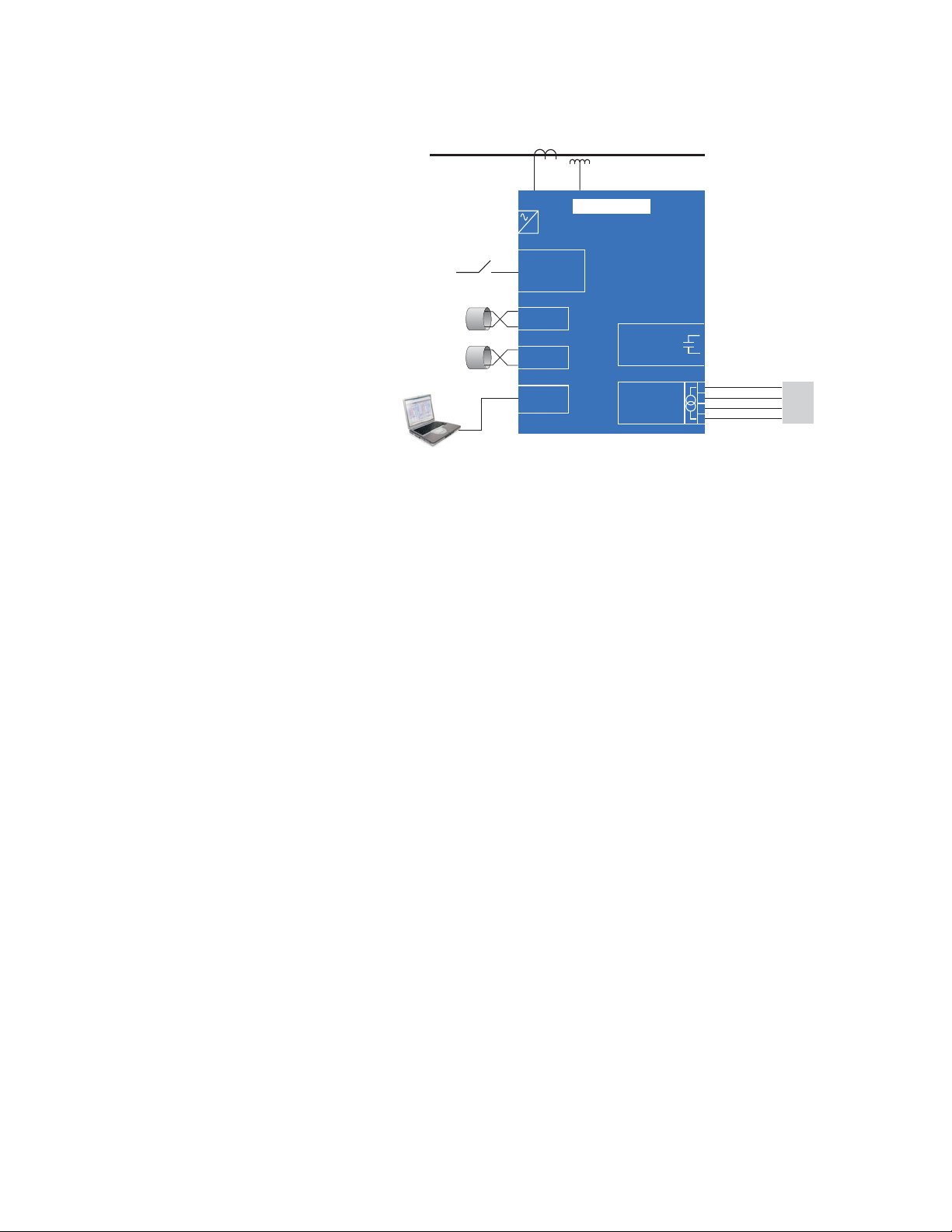
As a data gathering device for plant automation systems that integrate process,
instrument, and electrical requirements, all monitored values are available via one of two
RS485 communication ports running the Modbus protocol. If analog values are required
for direct interface to a PLC, any of the monitored values can output as a 4 to 20 mA (or 0
to 1 mA) signal to replace up to four (4) separate transducers. A third RS232
communication port connects to a PC from the front panel for simultaneous access of
information by other plant personnel.
With increasing use of electronic loads such as computers, ballasts, and variable
frequency drives, the quality of the power system is important. With the harmonic analysis
option, any phase current or voltage can be displayed and the harmonic content
calculated. Knowledge of the harmonic distribution allows action to be taken to prevent
overheated transformers, motors, capacitors, neutral wires, and nuisance breaker trips.
Redistribution of system loading can also be determined. The PQMII can also provide
waveform and data printouts to assist in problem diagnosis.
PQMII POWER QUALITY METER – INSTRUCTION MANUAL 1–1

1.1.2 Feature Highlights
• Monitoring: A, V, VA, W, var, kWh, kvarh, kVAh, PF, Hz
• Demand metering: W, var, A, VA
• Setpoints for alarm or control from most measured values, including: unbalance,
• four (4) output relays / four (4) switch inputs for flexible control configuration
• four (4) isolated analog outputs replace transducers for PLC interface
• one 4 to 20 mA analog input
• Modbus communications
• Three COM ports (two rear RS485 ports and one front RS232 port) for access by
• Harmonic analysis for power quality review and problem correction
• 40-character display and keypad for local programming
• No-charge EnerVista PQMII Setup Software
• Simulation mode for testing and training
• Compact design for panel mount
•AC/DC control power
CHAPTER 1: OVERVIEW
frequency, power factor, voltage, and current
process, electrical, maintenance, and instrument personnel
1.1.3 Applications of the PQMII
• Metering of distribution feeders, transformers, generators, capacitor banks, and
motors
• Medium and low voltage three-phase systems
• Commercial, industrial, utility
• Flexible control for demand load shedding, power factor, etc.
• Power quality analysis
• System debugging
1–2 PQMII POWER QUALITY METER – INSTRUCTION MANUAL
CHAPTER 1: OVERVIEW
Four (4)
output
relays
Four (4)
transducer
outputs
4
3
2
1
COM 2
RS232
PORT
COM 1
Four switch
inputs for
control
–
4to20mA
Alarm
control
Instrumentation
Electrical
Maintenance
Main
SCADA
Three-phase
3/4-wire bus
CTs
VTs
0 to 600 V direct
> 600V CT/VTs
Control
power
(AC/DC)
PLC
or
RTU
PQMII
PC running
EnerVista PQMII Setup
746701A1.CDR
FIGURE 1–1: Single Line Diagram
PQMII POWER QUALITY METER – INSTRUCTION MANUAL 1–3

CHAPTER 1: OVERVIEW
FIGURE 1–2: Feature Highlights
1–4 PQMII POWER QUALITY METER – INSTRUCTION MANUAL

CHAPTER 1: OVERVIEW
1.2 Standard Features
1.2.1 Metering
True RMS monitoring of Ia, Ib, Ic, In, Van, Vbn, Vcn, Vab, Vbc, Vca, voltage/current
unbalance, power factor, line frequency, watts, vars, VA, Wh, varh, VAh, and demand
readings for A, W, vars, and VA. Maximum and minimum values of measured quantities are
recorded and are date and time stamped.
A 40-character liquid crystal display is used for programming setpoints and monitoring
values and status.
1.2.2 Alarms
Alarm conditions can be set up for all measured quantities. These include overcurrent,
undercurrent, neutral current, current unbalance, voltage unbalance, phase reversal,
overfrequency, underfrequency, power factor, switch inputs, etc. The alarm messages are
displayed in a simple and easy to understand English format .
1.2.3 Communications
The PQMII is equipped with one standard RS485 port utilizing the Modbus or DNP
protocols. This can be used to integrate process, instrumentation, and electrical
requirements in a plant automation system by connecting several PQMII meters together
to a DCS or SCADA system. A PC running the EnerVista PQMII Setup Software can change
system setpoints and monitor values, status, and alarms. Continuous monitoring
minimizes process downtime by immediately identifying potential problems due to faults
or changes from growth.
The PQMII also includes a front RS232 port which can be used for the following tasks:
• data monitoring
• problem diagnosis
•viewing event records
•trending
• printing settings and/or actual values
• loading new firmware into the PQMII
1.2.4 Future Expansion
Flash memory is used to store firmware within the PQMII. This allows future product
upgrades to be loaded via the serial port.
PQMII POWER QUALITY METER – INSTRUCTION MANUAL 1–5

1.2.5 Open Architecture
PQMII units can initially be used as standalone meters. Their open architecture allows
connection to other Modbus compatible devices on the same communication link. These
can be integrated in a complete plant-wide system for overall process monitoring and
control.
CHAPTER 1: OVERVIEW
FIGURE 1–3: Downloading Product Enhancements via the Serial Port
1–6 PQMII POWER QUALITY METER – INSTRUCTION MANUAL
CHAPTER 1: OVERVIEW
1.3 Optional Features
1.3.1 Transducer Input/Outputs
Four isolated 4 to 20 mA (or 0 to 1 mA depending on the installed option) analog outputs
are provided that can replace up to eight transducers. The outputs can be assigned to any
measured parameters for direct interface to a PLC.
One 4 to 20 mA analog input is provided to accept a transducer output for displaying
information such as temperature or water level.
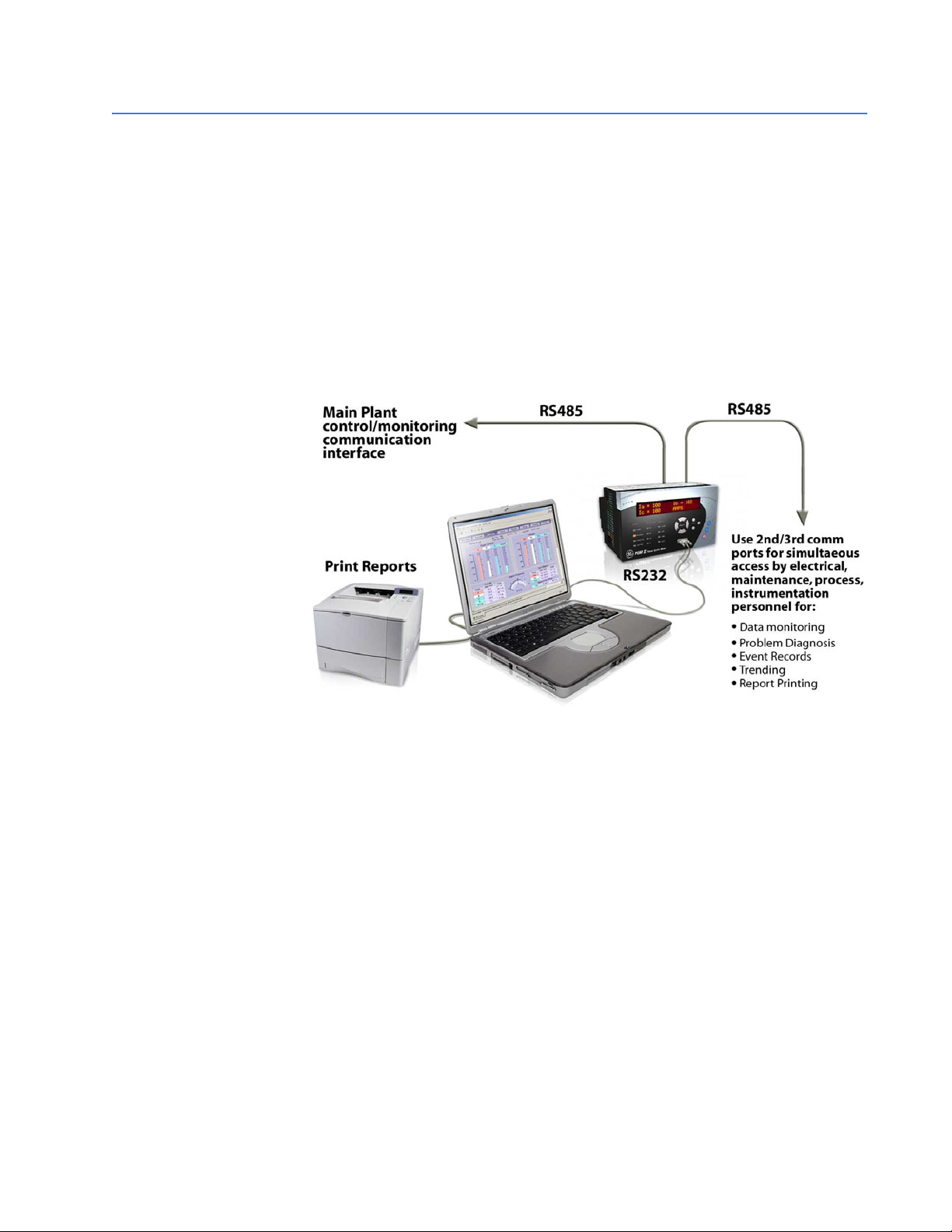
An additional rear RS485 communication port is provided for simultaneous monitoring by
process, instrument, electrical, or maintenance personnel.
FIGURE 1–4: Additional Communication Port
1.3.2 Control Option
An additional three dry-contact form “C” output relays and four dry-contact switch inputs
are provided. These additional relays can be combined with setpoints and inputs/outputs
for control applications. Possibilities include:
• undercurrent alarm warnings for pump protection
• overvoltage/undervoltage for generators
• unbalance alarm warnings to protect rotating machines
• dual level power factor for capacitor bank switching
• underfrequency/demand output for load shedding resulting in power cost saving
• kWh, kvarh and kVAh pulse output for PLC interface
• Pulse input for totalizing quantities such as kWh, kvarh, kVAh, etc.
PQMII POWER QUALITY METER – INSTRUCTION MANUAL 1–7
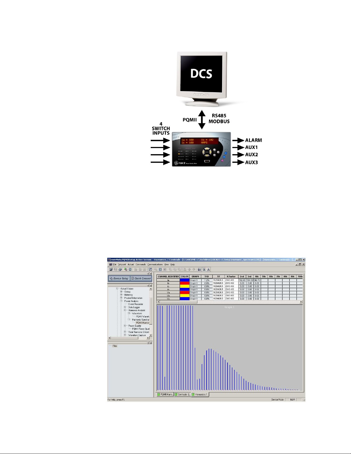
FIGURE 1–5: Switch Inputs and Outputs Relays
CHAPTER 1: OVERVIEW
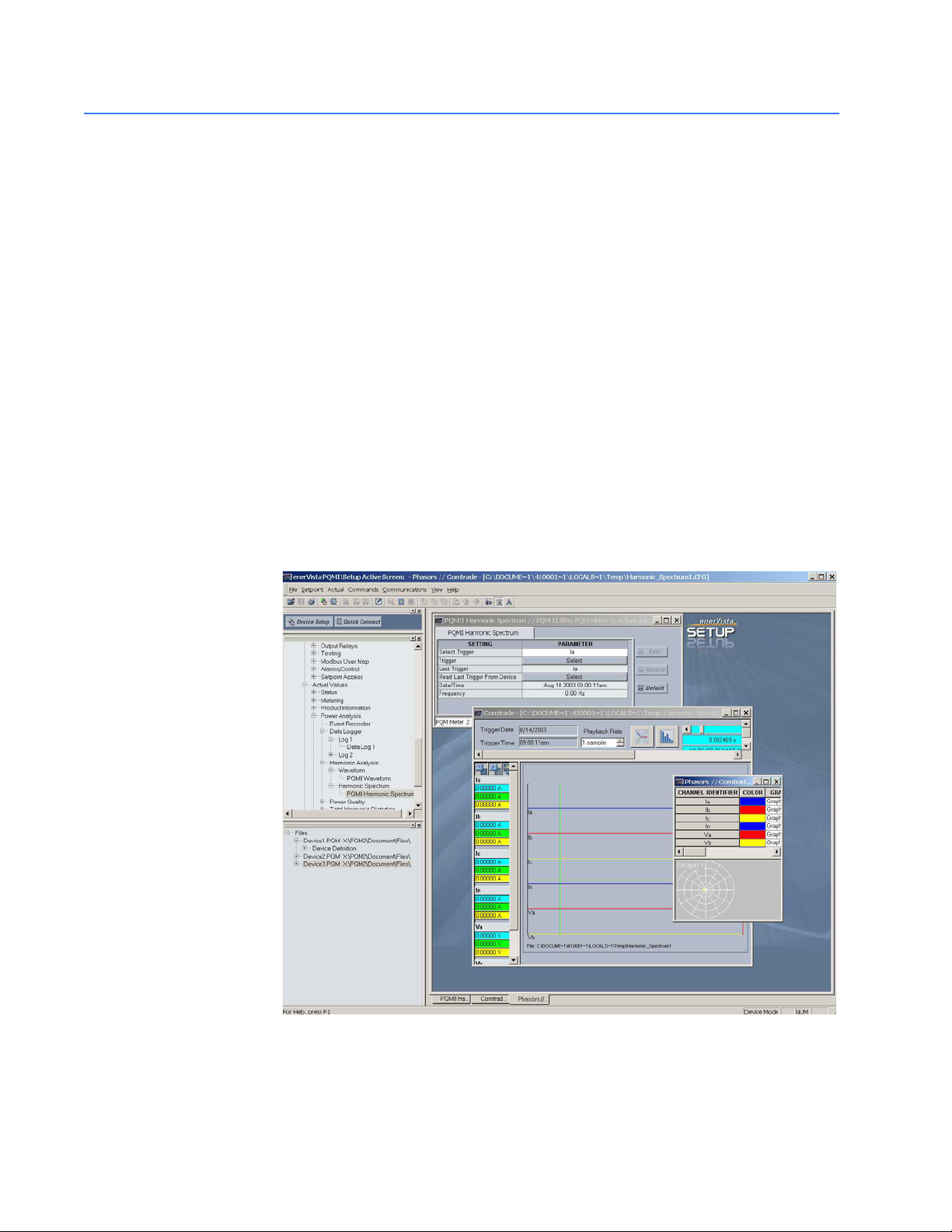
1.3.3 Power Analysis Option
Non-linear loads (such as variable speed drives, computers, and electronic ballasts) can
cause unwanted harmonics that may lead to nuisance breaker tripping, telephone
interference, and transformer, capacitor or motor overheating. For fault diagnostics such
as detecting undersized neutral wiring, assessing the need for harmonic rated
transformers, or judging the effectiveness of harmonic filters, details of the harmonic
spectrum are useful and available with the power analysis option.
FIGURE 1–6: Harmonic Spectrum
1–8 PQMII POWER QUALITY METER – INSTRUCTION MANUAL
CHAPTER 1: OVERVIEW
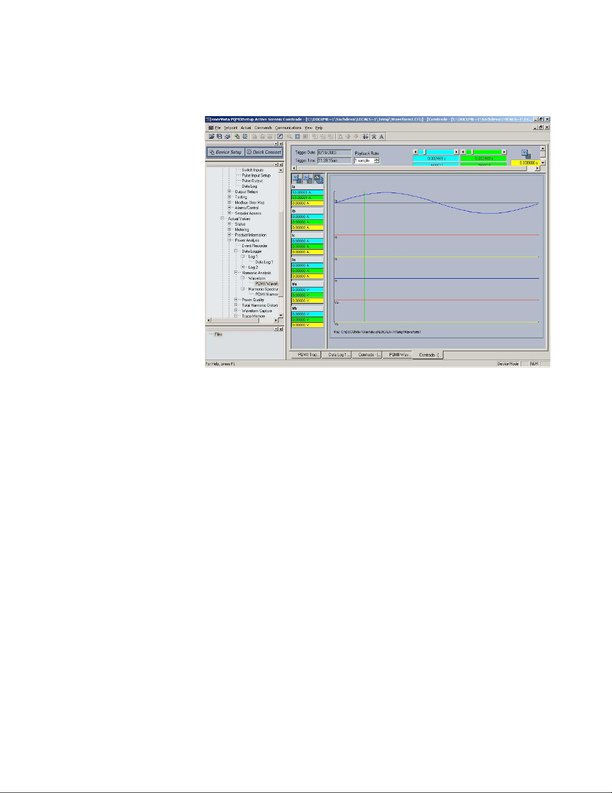
Voltage and current waveforms can be captured and displayed on a PC with the EnerVista
PQMII Setup Software or EnerVista Viewpoint. Distorted peaks or notches from SCR
switching provide clues for taking corrective action.
FIGURE 1–7: Captured Waveform
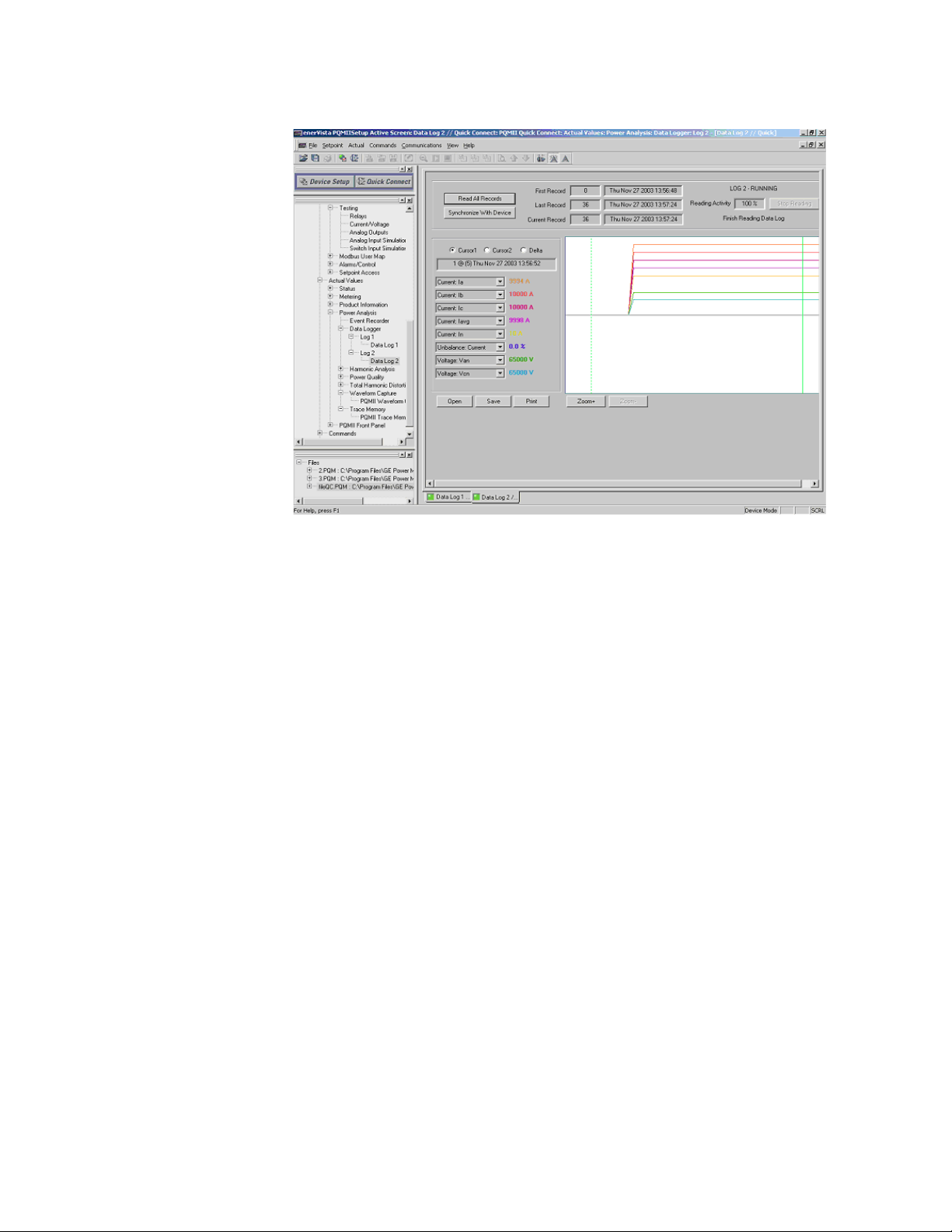
Alarms, triggers, and input/output events can be stored in a 150-event record and time/
date stamped by the internal clock. This is useful for diagnosing problems and system
activity. The event record is available through serial communication. Minimum and
maximum values are also continuously updated and time/date stamped.
PQMII POWER QUALITY METER – INSTRUCTION MANUAL 1–9
CHAPTER 1: OVERVIEW
FIGURE 1–8: Data Logger
Routine event logs of all measured quantities can be created, saved to a file, and/or
printed.
For additional information on waveform sampling and analysis features, see Power
Analysis on page 4–13.
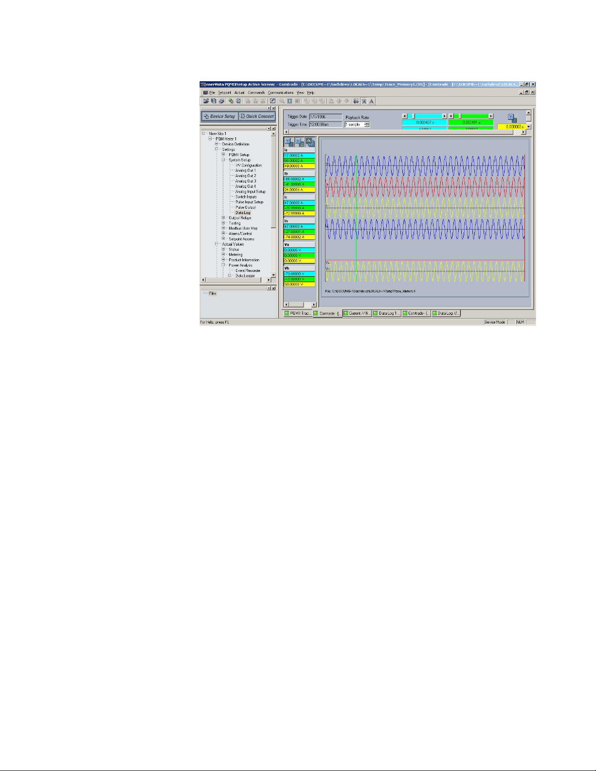
The power analysis option also provides a Trace Memory feature. This feature can be used
to record specified parameters based on the user defined triggers.
1–10 PQMII POWER QUALITY METER – INSTRUCTION MANUAL
CHAPTER 1: OVERVIEW
FIGURE 1–9: Trace Memory Capture
PQMII POWER QUALITY METER – INSTRUCTION MANUAL 1–11
1.4 EnerVista PQMII Setup Software
1.4.1 Overview
All data continuously gathered by the PQMII can be transferred to a third party software
program for display, control, or analysis through the communications interface. The
EnerVista PQMII Setup Software allows the user to view and manipulate this data and
assists in programming the PQMII. Some of the tasks that can be executed using the
EnerVista PQMII Setup Software package include:
• reading metered data
• monitoring system status
• changing PQMII setpoints on-line
• saving setpoints to a file and downloading into any PQMII
• capturing and displaying voltage and current waveforms for analysis
• recording demand profiles for various measured quantities
• troubleshooting communication problems with a built in debugger
• printing graphs, charts, setpoints, and actual values
CHAPTER 1: OVERVIEW
The EnerVista PQMII Setup Software is fully described in Software on page 4–1.
FIGURE 1–10: EnerVista PQMII Setup Software Main Window
1–12 PQMII POWER QUALITY METER – INSTRUCTION MANUAL

CHAPTER 1: OVERVIEW
1.5 Order Codes
1.5.1 Order Code Table
Power Analysis
The order code for all options is: PQMII-T20-C-A
Table 1–1: Order Codes
PQMII
Basic Unit PQMII –
Transducer
Option
Control
Option
Option
S S S
|
|
|
|
–
|
|
|
|
|
T1
|
|
|
|
|
|
|
C–||
T20 –
|
|
–
|
|
|
|
–
|
|
|
|
–
|
|
|
A
Basic unit with display, all current/voltage/power
measurements, one (1) RS485 communication port,
one (1) RS232 communication port
Four (4) isolated analog outputs, 0-20 mA and 4-20
mA assignable to all measured parameters, 4-20 mA
analog input, 2nd RS485 communication port
Four (4) isolated analog outputs, 0-1 mA assignable
to all measured parameters, 4-20 mA analog input,
2nd RS485 communication port
Three (3) additional programmable output relays (for
a total of 4), 4 programmable switch inputs
Harmonic analysis, triggered trace memory,
waveform capture, event recorder, data logger,
voltage disturbance recorder*
* The voltage disturbance recorder is only available with the 25 MHz processor.
1.5.2 Modifications
Consult the factory for any additional modification costs):
1.5.3 Accessories
Consult the factory for any additional accessory costs:
• MOD 501: 20 to 60 V DC / 20 to 48 V AC Control Power
• MOD 502: Tropicalization
• MOD 504: Removable Terminal Blocks
• MOD 506: 4-Step Capacitor Bank Switching (Available with Option "C" only)
• EnerVista PQMII Setup Software (included with the PQMII; also available at http://
www.enerVista.com)
• RS232 to RS485 converter (required to connect a PC to the PQMII RS485 ports)
• GE MultiNET RS485 serial-to-Ethernet converter (required for connection to an
Ethernet network)
• RS485 terminating network
1.5.4 Control Power
• 90 to 300 V DC / 70 to 265 V AC standard
• 20 to 60 V DC / 20 to 48 V AC (MOD 501)
PQMII POWER QUALITY METER – INSTRUCTION MANUAL 1–13

1.6 Specifications
CHAPTER 1: OVERVIEW
Note
Specifications are subject to change without notice.
1.6.1 Inputs/Outputs
CURRENT INPUTS
Conversion:...................................................true RMS, 64 samples/cycle
CT Input: ......................................................... 1 A and 5 A secondary
Burden: ........................................................... 0.2 VA
Overload: .......................................................20 × CT for 1 sec.
100 × CT for 0.2 sec.
Range:............................................................. 1 to 150% of CT primary
Full Scale:.......................................................150% of CT primary
Frequency: ....................................................up to 32nd harmonic
Accuracy:.......................................................±0.2% of full scale at <1.20 x CT
VOLTAGE INPUTS
Conversion:...................................................true RMS, 64 samples/cycle
VT pri./sec.:....................................................120 to 72000 : 69 to 240, or Direct
VT Ratio: .........................................................1:1 to 3500:1
Burden: ........................................................... 2.2 MΩ
Input Range:.................................................40 to 600 V AC
Full scale:
for VT input ≤150 V AC: ...................... 150 V AC
for VT input >150 V AC: ...................... 600 V AC
Frequency: ....................................................up to 32nd harmonic
Accuracy:.......................................................±0.2% of full scale
SWITCH INPUTS
Type:.................................................................dry contacts
Resistance:....................................................1000 Ω max ON resistance
Output:............................................................24 V DC at 2 mA (pulsed)
Duration: ........................................................ 100 ms minimum
ANALOG OUTPUT (0–1 MA)
Max. load: ...................................................... 2400 Ω
Max. output: ................................................. 1.1 mA
Accuracy:.......................................................±1% of full-scale reading
Isolation:......................................................... ±36 V DC isolated, active source
ANALOG OUTPUT (4–20 MA)
Max. load: ...................................................... 600 Ω
Max. output: ................................................. 21 mA
Accuracy:.......................................................±1% of full-scale reading
Isolation:......................................................... ±36 V DC isolated, active source
PULSE OUTPUT
Parameters:..................................................+kWh, –kWh, +kvarh, –kvarh, kVAh
Interval:........................................................... 1 to 65000 in steps of 1
Pulse width: ..................................................100 to 2000 ms in steps of 10
Minimum pulse interval: ........................500 ms
Accuracy:.......................................................±10 ms
1–14 PQMII POWER QUALITY METER – INSTRUCTION MANUAL

CHAPTER 1: OVERVIEW
1.6.2 Trace Memory Trigger
1.6.3 Sampling Modes
PULSE INPUT
Max. inputs:.................................................. 4
Min. pulse width: ....................................... 150 ms
Min. off time:................................................ 200 ms
TRACE MEMORY TRIGGER
Input................................................................ 2 data cycles (current, voltage)
Time delay:................................................... 0 to 30 cycles
Current input full scale: ......................... 150% of CT primary
Voltage input full scale: ......................... 600 V AC
TRIGGER LEVEL PICKUP ACCURACY
Overcurrent:................................................. ±2% of full scale
Overvoltage: ................................................ ±2% of full scale
Undervoltage: ............................................ ±3% of full scale
METERED VALUES
Samples per cycle: ................................... 64
Inputs sampled at a time: .................... all
Duration:........................................................ 2 cycles
TRACE MEMORY
Samples per cycle: ................................... 16
Inputs sampled at a time: .................... all
Duration:........................................................ continuous
HARMONIC SPECTRUM
Samples per cycle: 256
Inputs sampled at a time: 1
Duration:........................................................ 1 cycle
VOLTAGE DISTURBANCE RECORDER
Samples per half-cycle: ......................... 8
Inputs sampled: ........................................ all measured voltages
Duration: ...................................................... 0.5 cycles to 1 minute
1.6.4 Output Relays
MAKE/CARRY
Continuous:.................................................. 5 A
0.1 second: ................................................... 30 A
BREAK
Resistive:........................................................ 5 A at 30 V DC, 125/250 V AC
0.5 A at 125 V DC
0.3 A at 250 V DC
Inductive (L/R = 7 ms):............................. 5 A at 30 V DC, 125/250 V AC
0.25 A at 125 V DC
0.15 A at 250 V DC
PQMII POWER QUALITY METER – INSTRUCTION MANUAL 1–15

1.6.5 Metering
MEASURED VALUES ACCURACY (SPECIFIED FOR 0 TO 40°C)
Voltage:...........................................................±0.2% of full-scale
Current:........................................................... ±0.2% of full-scale
Voltage unbalance: ..................................±1% of full-scale
Current unbalance: ..................................±1% of full-scale
kW:....................................................................±0.4% of full scale
kvar: ................................................................ ±0.4% of full scale
kVA: .................................................................. ±0.4% of full scale
kWh: ................................................................±0.4% of full scale
kvarh: .............................................................. ±0.4% of full scale
kVAh: ...............................................................±0.4% of full scale
Power factor: ...............................................±1% of full-scale
Frequency: ....................................................±0.02 Hz
kW demand:.................................................±0.4% of full-scale
kvar demand:...............................................±0.4% of full-scale
kVA demand:................................................ ±0.4% of full-scale
Current demand: .......................................±0.4% of full-scale
Current THD:.................................................±2.0% of full-scale
Voltage THD: ................................................ ±2.0% of full-scale
Crest factor:..................................................±0.4% of full-scale
MEASURED VALUES RANGE
Voltage:...........................................................20 to 100% of VT
Current:........................................................... 1 to 150% of CT
Voltage unbalance: ..................................0 to 100%
Current unbalance: ..................................0 to 100%
Real power:...................................................0 to ±999,999.99 kW
Reactive power: ......................................... 0 to ±999,999.99 kvar
Apparent power: .......................................0 to 999,999.99 kVA
32
Real energy:.................................................. 2
Reactive energy: ........................................2
Apparent energy: ......................................2
32
32
kWh
kvarh
kVAh
Power factor: ............................................... 0.00 to ±1.00
Frequency: ....................................................20.00 to 70.00 Hz
kw demand:.................................................. 0 to ±999,999.99 kW
kvar demand:...............................................0 to ±999,999.99 kvar
kVA demand:................................................ 0 to 999,999.99 kVA
Current demand: .......................................0 to 7500 A
THD (current and voltage): ...................0.0 to 100.0%
Crest factor:..................................................1 to 9.99
CHAPTER 1: OVERVIEW
1.6.6 Monitoring
UNDERVOLTAGE MONITORING
Req’d voltage: ............................................. >20 V applied in all phases
Pickup:.............................................................0.50 to 0.99 × VT in steps of 0.01
Dropout: .........................................................103% of pickup
Time delay: ...................................................0.5 to 600.0 s in steps of 0.5
Phases:............................................................Any 1 / Any 2 / All 3 (programmable) have to be ≤
pickup to operate
Accuracy:.......................................................per voltage input
1–16 PQMII POWER QUALITY METER – INSTRUCTION MANUAL

CHAPTER 1: OVERVIEW
Timing accuracy: ...................................... –0 / +1 sec.
OVERVOLTAGE MONITORING
Pickup: ............................................................ 1.01 to 1.25 × VT in steps of 0.01
Dropout:......................................................... 97% of pickup
Time delay:................................................... 0.5 to 600.0 s in steps of 0.5
Phases:........................................................... Any 1 / Any 2 / All 3 (programmable) must be ≥ pickup
to operate
Accuracy: ...................................................... Per voltage input
Timing accuracy: ...................................... –0 / +1 sec.
UNDERFREQUENCY MONITORING
Req’d voltage: ............................................ >30 V applied in phase A
Pickup: ............................................................ 20.00 to 70.00 Hz in steps of 0.01
Dropout:......................................................... Pickup + 0.03 Hz
Time delay:................................................... 0.1 to 10.0 s in steps of 0.1
Accuracy: ...................................................... 0.02 Hz
Timing accuracy: ±100 ms
OVERFREQUENCY MONITORING
Req’d voltage: ............................................ >30 V applied in phase A
Pickup: ............................................................ 20.00 to 70.00 Hz in steps of 0.01
Dropout:......................................................... Pickup – 0.03 Hz
Time delay:................................................... 0.0 to 10.0 s in steps of 0.1
Accuracy: ...................................................... 0.02 Hz
Timing accuracy: ±100 ms
POWER FACTOR MONITORING
Req’d voltage: ............................................ >20 V applied in phase A
Pickup: ............................................................ 0.50 lag to 0.50 lead step 0.01
Dropout:......................................................... 0.50 lag to 0.50 lead step 0.01
Time delay:................................................... 0.5 to 600.0 s in steps of 0.5
Timing accuracy: ...................................... –0.5/+1 sec.
DEMAND MONITORING
Measured values: ..................................... Phase A/B/C/N Current (A)
3φ Real Power (kW)
3φ Reactive Power (kvar)
3φ Apparent Power (kVA)
Measurement type (programmable):
Thermal Exponential, 90% response time: 5 to 60 min. in steps of 1
Block interval: ............................................ 5 to 60 min. in steps of 1
Rolling Demand Time Interval: .......... 5 to 60 min. in steps of 1
Pickup: ............................................................ 10 to 7500 A in steps of 1
1 to 65000 kW in steps of 1
1 to 65000 kvar in steps of 1
1 to 65000 kVA in steps of 1
VOLTAGE DISTURBANCE RECORDER
Required voltage: ..................................... >20 V or 10% (whichever is greater) applied in each
measured phase
Minimum nominal voltage: .................. 60 V
Phases recorded: ...................................... all three phases recorded independently
Conversion: .................................................. true RMS, 8 samples/half-cycle
Sag:
Pickup level: .............................................. 0.20 to 0.90 × VT in steps of 0.01
Dropout level: .......................................... pickup + 10% of nominal
PQMII POWER QUALITY METER – INSTRUCTION MANUAL 1–17

1.6.7 System
CHAPTER 1: OVERVIEW
Swell:
Pickup level: ..............................................1.01 to 1.50 × VT in steps of 0.01
Dropout level: ...........................................pickup – 10% of nominal
COMMUNICATIONS
COM1/2: .........................................................RS485 2-wire, half duplex, isolated
COM3:..............................................................RS232 9-pin
Baud rate:......................................................1200 to 19200
®
Protocols:.......................................................Modbus
RTU; DNP 3.0
Functions:......................................................Read/write setpoints, read actual values, execute
commands, read device status
loopback test
CLOCK
Accuracy:.......................................................±1 min. / 30 days at 25±5°C
Resolution:.....................................................1 sec.
CONTROL POWER
Input:................................................................ 90 to 300 V DC or 70 to 265 V AC at 50/60 Hz
Power: ............................................................. nominal 10 VA, max. 20 VA
Holdup: ........................................................... 100 ms typical (at 120 V AC / 125 V DC)
It is recommended that the PQMII be powered up at least once per year to avoid
deterioration of the electrolytic capacitors in the power supply.
FUSE TYPE/RATING
5 × 20mm, 2.5 A, 250V
Slow blow, High breaking capacity
1.6.8 Testing and Approvals
TYPE TESTS
TEST REFERENCE STANDARD TEST LEVEL
Dielectric voltage withstand 2300-3700VAC
Impulse voltage withstand EN60255-5 5KV
Insulation resistance 500VDC >100mohm
Damped Oscillatory IEC61000-4-18IEC60255-22-1 2.5KV CM, 1KV DM
Electrostatic Discharge EN61000-4-2/IEC60255-22-2 Level II
RF immunity EN61000-4-3/IEC60255-22-3 10V/m 80-1Ghz
Fast Transient Disturbance EN61000-4-4/IEC60255-22-4 Class A and B
Surge Immunity EN61000-4-5/IEC60255-22-5 4Kv, 2KV
Conducted RF Immunity EN61000-4-6/IEC60255-22-6 10Vrms
Radiated & Conducted Emissions CISPR11 /CISPR22/ IEC60255-25 Class A
1–18 PQMII POWER QUALITY METER – INSTRUCTION MANUAL

CHAPTER 1: OVERVIEW
Sinusoidal Vibration IEC60255-21-1 Class 1
Shock & Bump IEC60255-21-2 Class 1
Power magnetic Immunity IEC61000-4-8 Level 4
Pulse Magnetic Immunity IEC61000-4-9 Level 4
Voltage Dip & interruption IEC61000-4-11
0,40,70,% dips,250/
300cycle interrupts
Ingress Protection IEC60529 IP40 front , IP20 Back
Environmental (Cold) IEC60068-2-1 -10C 16 hrs
Environmental (Dry heat) IEC60068-2-2 70C 16hrs
Relative Humidity Cyclic IEC60068-2-30 6day variant 2
EFT IEEE/ANSI C37.90.1 4KV, 2.5Khz
Damped Oscillatrory IEEE/ANSI C37.90.1 2.5KV,1Mhz
Altitude: 2000m (max)
Pollution Degree: II
Overvoltage Category: II
Ingress protection: IP40 Front , IP20 back
APPROVALS
APPROVALS
Applicable Council Directive According to
Low voltage directive EN60255-5
CE compliance EMC Directive EN61000-6-2
UL508
North America cULus e83849 NKCR/7 UL1053
C22.2.No 14
ISO
Manufactured under a registered
quality program
ISO9001
ENVIRONMENTAL
Ambient temperatures:
Operating range: -10C to 60C
Humidity:
PQMII POWER QUALITY METER – INSTRUCTION MANUAL 1–19
Operating up to 95% (non condensing) @ 55C (As per
IEC60068-2-30 Variant 2, 6days)

1.6.9 Physical
CHAPTER 1: OVERVIEW
No special ventilation required as long as ambient
Ventillation:
temperature remains within specifications.
Ventilation may be required in enclosures exposed to
direct sunlight.
Cleaning: May be cleaned with a damp cloth.
PACKAGING
Shipping box: .............................................. 8½” × 6” × 6” (L × H × D)
21.5cm × 15.2cm × 15.2 cm
1–20 PQMII POWER QUALITY METER – INSTRUCTION MANUAL
Digital Energy
Multilin
PQMII Power Quality Meter
Chapter 2: Installation
Installation
2.1 Physical Configuration
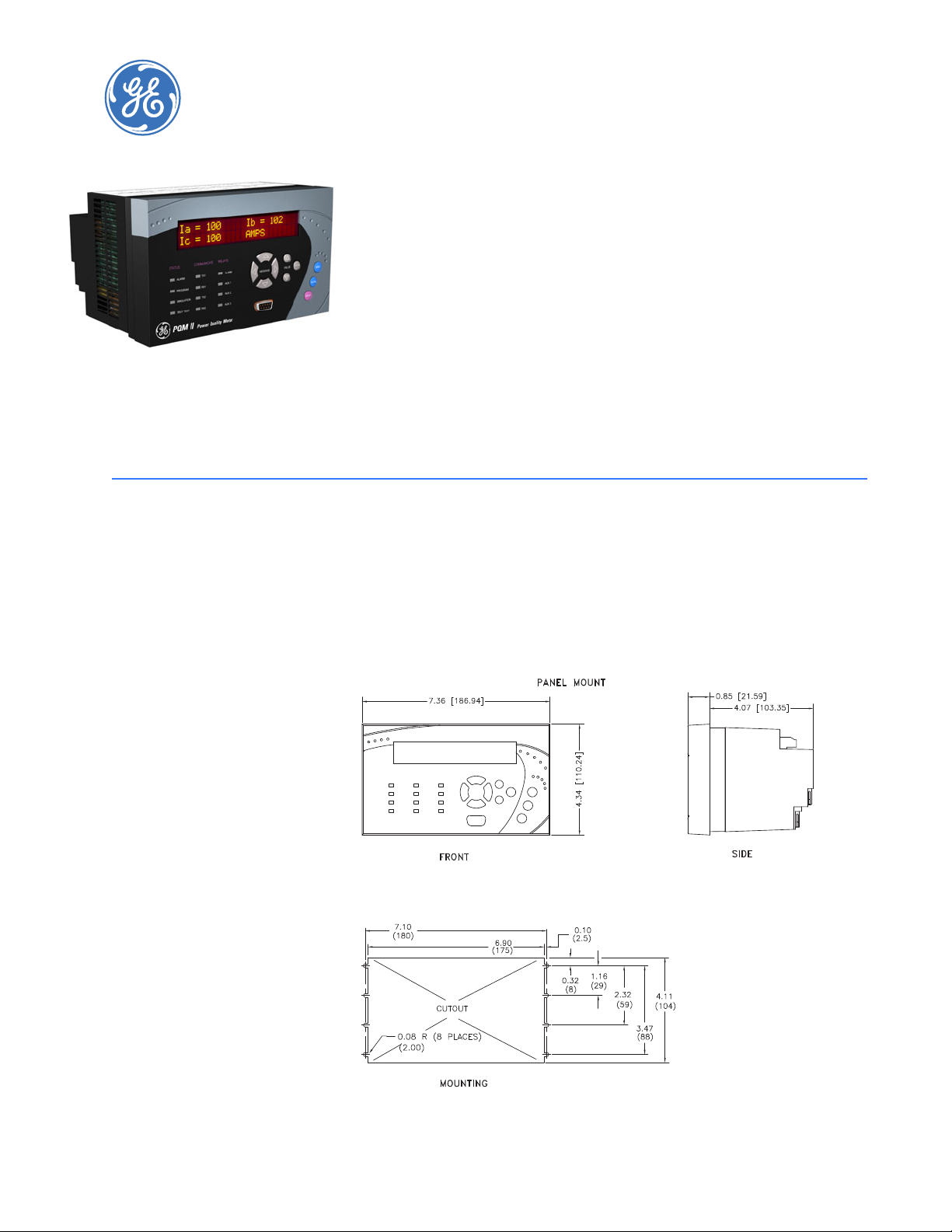
2.1.1 Mounting
Physical dimensions and required cutout dimensions for the PQMII are shown below. Once
the cutout and mounting holes are made in the panel, use the eight #6 self-tapping screws
provided to secure the PQMII. Mount the unit on a panel or switchgear door to allow
operator access to the keypad and indicators.
FIGURE 2–1: Physical Dimensions
PQMII POWER QUALITY METER – INSTRUCTION MANUAL 2–1
2.1.2 Product Identification
20
19
18
17
16
15
141312
11
10
9
MAXIMUM CONTACT RATING
250 VAC 10A RESISTIVE
1/4HP 250VAC 1/2HP 125VAC
PQM II
MODEL NO.:
CONTROL VOLTAGE: SERIAL No.:
VERSION:
CUSTOMER TAG No.: 1234-567-89
90-300VDC 20VA
70-265VAC 50/60HZ 20VA
100.000
C7360001
PQMII-T20-C-A
MADE IN
CANADA
g
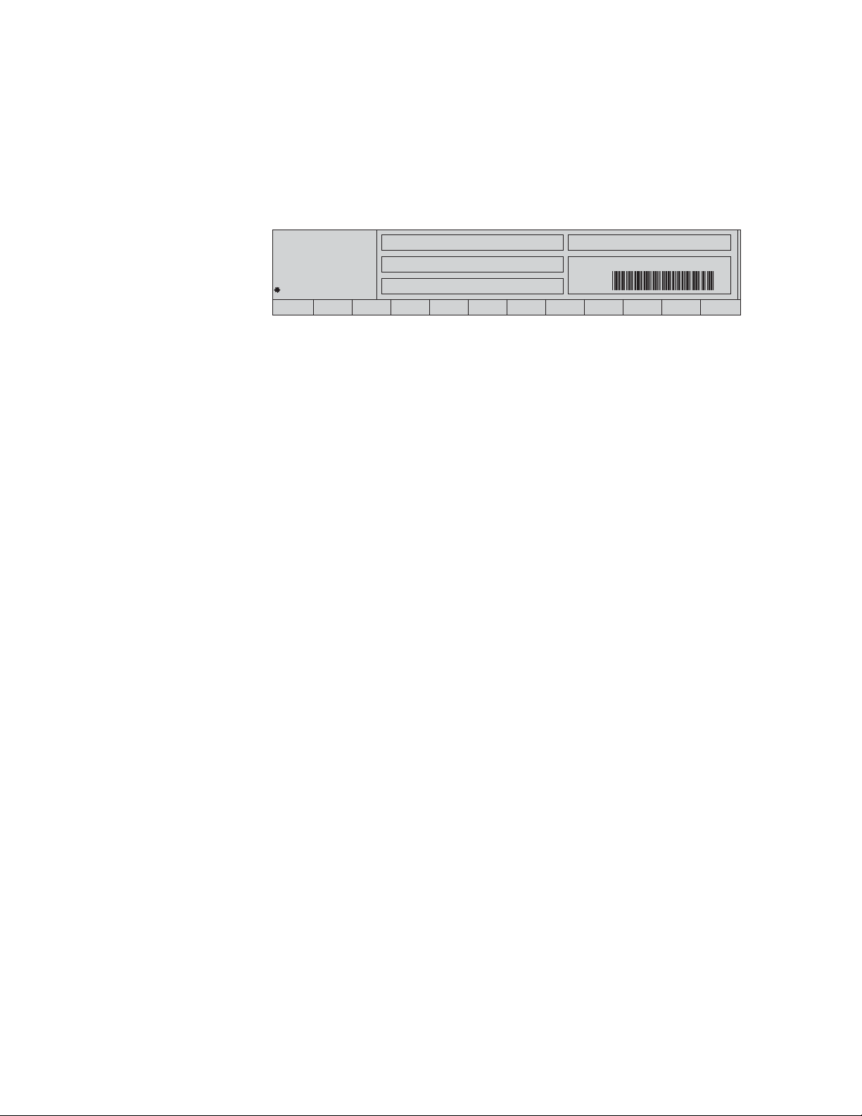
Product attributes vary according to the configuration and options selected on the
customer order. Before applying power to the PQMII, examine the label on the back and
ensure the correct options are installed.
The following section explains the information included on the label shown below:
• Model No: Shows the PQMII configuration. The model number for a basic panel
mount PQMII is “PQMII”. T20, C, and A appear in the model number only if the
Transducer, Control, or Power Analysis options are installed.
• Supply Voltage: Indicates the power supply input configuration installed in the
PQMII. The PQMII shown in this example can accept any AC 50/60Hz voltage from
70 to 265 V AC or DC voltage from 90 to 300 V DC.
• Tag#: An optional identification number specified by the customer.
• Mod#: Indicates if any unique features have been installed for special customer
orders. This number should be available when contacting GE Multilin for technical
support.
• Version: An internal GE Multilin number that should be available when contacting
us for technical support.
• Serial No.: Indicates the serial number in numeric and barcode formats. Record
this number when contacting GE Multilin for technical support .
CHAPTER 2: INSTALLATION
FIGURE 2–2: Product Label
2–2 PQMII POWER QUALITY METER – INSTRUCTION MANUAL
2.1.3 Manual and Firmware Revisions
Each instruction manual revision corresponds to a particular firmware revision. The
manual revision is located on the title page as part of the manual part number (the format
is 1601-nnnnmanual part number, and is also loaded in the PQMII, where it can be viewed by scrolling
to the
A4 PRODUCT INFO ÖØ SOFTWARE VERSIONS ÖØ MAIN PROGRAM VERSION message.
When using the instruction manual to determine PQMII features and settings, ensure that
the instruction manual revision corresponds to the firmware revision installed in the PQMII.
revision). The firmware revision is located on that same page, just above the
 Loading...