

GE PowerMark Gold Installation Instructions Manual
© 2016 General Electric All Rights Reserved
1
WARNING: Hazard of electrical shock or burn. Turn off
power supplying this equipment before working inside
General
To comply with the National Electrical Code and
Underwriters Laboratories, the breaker retainer kit and
service barrier must be installed in accordance with the
information contained in this sheet and by a qualified
electrical contractor and/or licensed electrician.
Introduction
This bulletin provides instructions for installing circuit breaker
retainer and Service barrier to Model 6 PowerMark GoldTM GE
Load centers. The retainer is used to secure a 2-pole branch
breaker on the load center interior when the breaker is used
as a back-fed main circuit breaker. And Service barriers are
installed on the line side of the breaker.
Contents per Installation
THQLRK4 - Main Breaker Retainer & Service Barrier Kit
Description
Qty.
AUX. BREAKER RETAINER
1
JAM NUT HEX
2
THQL Lug Barrier
2
LABEL
1
NOTICE: These instructions do not purport to cover all
details or variations in equipment or to provide for every
possible contingency to be met in connection with the
installation, operation or maintenance. Should further
information be desired or should particular problems arise
which are not covered sufficiently for the purposes, the
matter should be referred to the General Electric Company.
These instructions are intended for use by qualified
personnel only.
Installation Instructions
1. Uninstall the Dead front/shield and retain the
mounting screws.
2. Install the 2-pole back-fed main circuit breaker (D) in
position 2-4 or 1-3 only. See the load center directory
label or numbers stamped on the dead front/shield to
locate position.
Use only a General Electric type THQL or THHQL twopole circuit breaker.
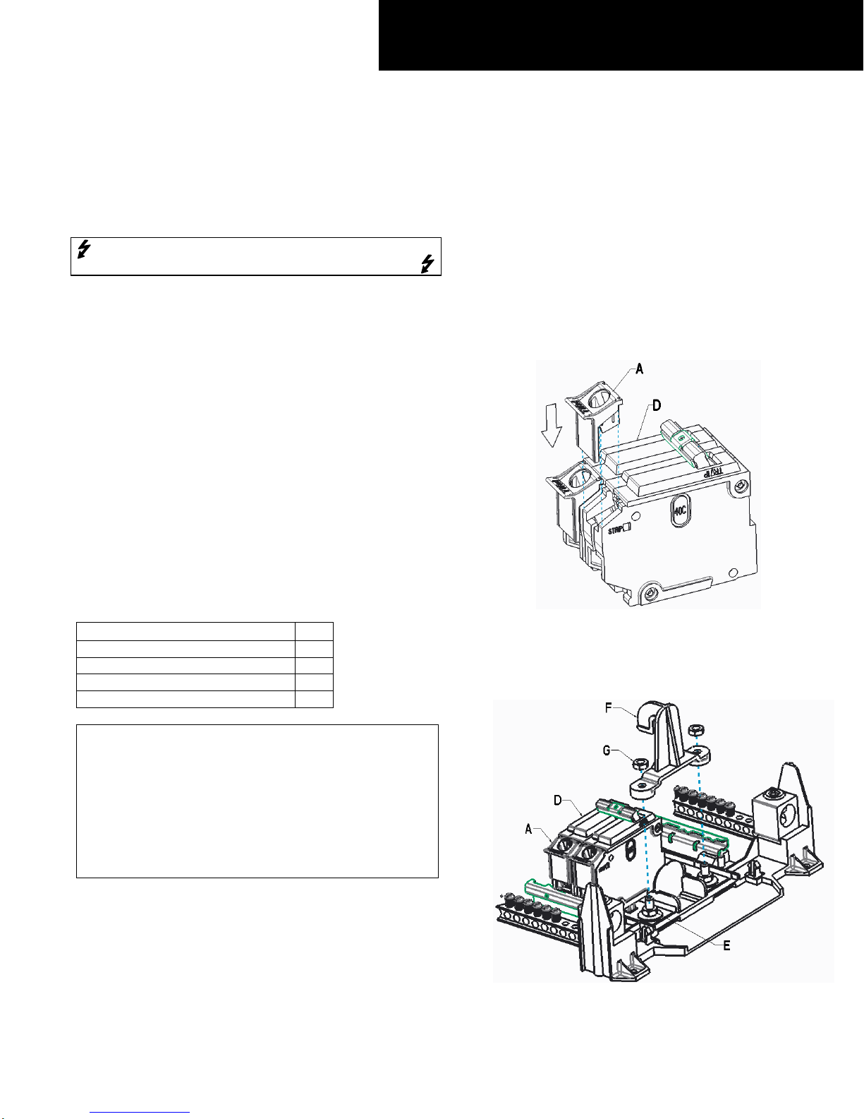
3. Insert the Service Barriers (A) onto line side of circuit
breaker (D) as shown in Figure 1. Two Service Barriers
included with the kit, need to assemble to both the
poles.
Figure 1: Insert Service Barrier onto Main Circuit Breaker
4. Install the retainer (F), over existing nuts (E), and
secure with the 2 nuts (G) provided with the kit.
Tighten to 35 lb-in (4Nm). See figure 2
g
PowerMark Gold ™
Load Centers
PowerMark GoldTM Model 6 Breaker Retainer & Service Barrier Kit Cat# THQLRK4
DEH41481 Installation Instructions
© 2016 General Electric All Rights Reserved
2
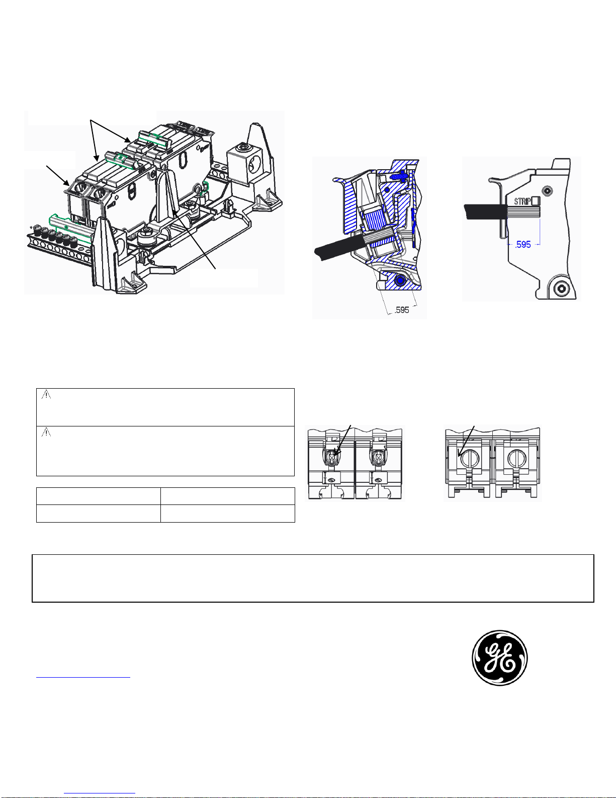
Figure 2: Install Retainer to secure breaker
See figure 3, load center fully assembled with kit
Figure 3: shows Kit fully assembled
5. Remove the backing from the enclosed "SERVICE
DISCONNECT" label and attach it to the dead
front/shield besides the main circuit breaker opening.
WARNING: Service barriers (A) must be correctly
installed on the line side of a main device in GE load
centers, and MSLC to ensure isolation from live parts.
WARNING: Installing an incorrect size wire than the
specified sizes for each circuit breaker frame will negate
the barrier ability to protect personnel from exposed live
components.
Location
Conductors
Lug Hole
10 AWG to 2/0 AWG Cu/Al
Table 1: Shows the allowable wire range for the barrier.
The wires must be stripped to the correct length to maintain
isolation. Strip the wire to a maximum of 0.595 inches.
After stripping the wires to the required length, the wires can
be installed as shown in Figure 4. The service barrier must be
correctly installed to maintain electrical isolation from
accidental contact. Torque the wires according the torque
specification on the breaker.
Figure 4: Stripped wire installed
The strip wire length are measured to the scale provided on
side of main circuit breaker, as shown on Figure 5.
Some THQL (1p and 2p up to 60 Amps) are finger safe and do
not require a Service barrier. See Figure 6.
Barriers not required Barriers required
Figure 6: Breakers Where Service Barriers Are Required
Imagination at work
GE Configured Solutions
41 Woodford Ave.
Plainville, CT 06062
www.geindustrial.com
To contact GE Industrial Solutions post sales service team, call 888-437-3765
*INDICATES A TRADEMARK OF THE GENERAL ELECTRIC COMPANY AND/OR ITS SUBSIDIARIES.
INFORMATION PROVIDED IS SUBJECT TO CHANGE WITHOUT NOTICE. PLEASE VERIFY ALL DETAILS WITH GE. ALL VALUES ARE DESIGN OR TYPICAL WHEN MEASURED UNDER LABORATORY CONDITIONS, AND GE MAKES
NO WARRANTY OR GUARANTEE, EXPRESS OR IMPLIED, THAT SUCH PERFORMANCE WILL BE OBTAINED UNDER END-USE CONDITIONS
These instructions do not purport to cover all details or variations in equipment nor do they provide for every possible
contingency that may be met in connection with installation, operation, or maintenance. Should further information be desired
or should particular problems arise that are not covered sufficiently for the purchaser’s purposes, the matter should be
referred to the GE Company.
Figure 5: Max. Strip Wire Length.
Oval
Square
Main Circuit Breaker
Position 2-4 or 1-3 only
Retainer
Barrier
 Loading...