

GE PNRQ15RBL00 Owner’s Manual
0_
E
4.z
®l
4.z
E
0
0
GEAppliances.corn
Safety Instructions
Safety Instructions ................ 2, 5
Specification Guidelines ............. 4
Operating Instructions
About the ROSystem ............. 5, 6
Installation Instructions
Tools and Materials Required ........ 7
Before Beginning Installation ...... 7, 8
Mounting System Installation ........ 9
Feed Water Supply ............. 10-13
Faucet Assembly ............... 14, 15
Battery Installation ................ 15
Filtration Drain Connection ..... 16, 17
Storage Tank and Startup .......... 18
PNRQ15RBL
PXRQ15RBL
Osmose Invers
Syst_me de Filtration
La section fran_aise commence _ la page 27
0
>
®l
LL
Care and Cleaning
prefilter, Postfilter and
RO Cartridge Replacement ......... 19
Sanitization ........................ 20
Water Test Kit ..................... 21
Troubleshooting Tips ...... 22, 25
Consumer Support
Consumer Support ........ Back Cover
Parts List/Catalog .............. 24, 25
Warranty .......................... 26
PXRQ15RBLand PNRQ15RBLare Testedand
Certified to NSF/ANSI Standards 58and 42
and CSAB483.1for the reduction of the claims
as specified on the Performance Data Sheet.
Osmosis Inversa
Sistema de Filtrocidn
La secci6n en espafol empieza en la p6gina 55
Write the model and serial
numbers here:
Model #
Serial #
Youcan find them on the bracket.
1010190310 49-50261-1 09-10GE
IMPORTANT SAFETY INFORMATION.
READ ALL INSTRUCTIONS BEFORE USING.
SAFETY INFORIVlATION
Read,understand,and follow all safetyinformation containedin theseinstructionspriorto installationand useof the GEReverse
Osmosissystems.Retaintheseinstructionsfor future reference.
Intended use:
TheGEReverseOsmosissystemsare intendedfor use infiltering potable water in Residentialapplications,and has not been
evaluatedfor other uses.Thesystemistypicallyinstalledat the point of use,and mustbe installedas specifiedin the installation
instructions.Contacta plumbingprofessionalif you are uncertain how to install.
This is the safety alert symbol. It is used to alert you to potential personal injury hazards. Obey all safety
messages that follow this symbol to avoid possible injury or death.
_W WARNINGindicates a potentially hazardous situation which, if not avoided, could result in death
_, CAUTIONindicates a potentially hazardous situation which, if not avoided, may result in minor to
ARNING orseriousinjury.
CAUTION moderateinjury.
CAUTION CAUTIONused without the safety alert symbol indicates a potentially hazardous situation which, if
not avoided, may result property damage.
SAFETY PRECAUTIONS
I Besurethe water supplyconformswith the
SpecificationGuidelines.if the water supplyconditions
are unknown,contact your municipalwater company
or your local health department for a listof
contaminantsin your area and a listof laboratories
certified byyourstate to analyzedrinkingwater.
WARNINGTOreduce the risk associated
with choking:
• Do not allowchildrenunder 3years of age to have
accessto smallparts duringthe installationof this
product.
WARNINGTOreducethe riskassociatedwith
theingestionofcontaminants:
• Donotusewithwaterthatismicrobiologicallyunsafeorof
unknownqualitywithoutadequatedisinfectionbeforeor
afterthesystem.Systemscertifiedfor cystreductionmay
beusedondisinfectedwaterthat maycontainfilterable
cysts.EPAEstablishment#10350-iVlN-005.
installa water hammer arrester.Contacta plumbing
professionalif you are uncertainhow to checkfor this
condition.
• Wherea backflow preventiondeviceis installedona
water system,a deviceforcontrolling pressuredueto
thermal expansionmustbe installed.
_1_ WARNING To reducethe risk associated
with irritation from SodiumHetabisulphite during
installation:
• SodiumiVletabisulphite(CAS007681-57-/4)isusedina 1%
preservativesolutionwithinthe reverseosmosis
membrane.
• Torequest an HSDSrelating to this product call 203-
238-8965or visit the web at
http://sotutions.3m.com/wps/portat/3m/en_us/
msds(click HSDSsearch}.Foremergencies,call 800-
364-3577or 651-737-6501(24hours}.
A WARNINGToreducethe risk associated
A WARNINGTo reduce the riskassociated
with hazardousvoltage due to an installer drilling
through existing electric wiring or water pipesin the
area of installation:
• Do not install nearelectricwiring or pipingwhich may
be in path of a drillingtool when selectingthe position
to mount the filter bracket.
A WARNINGToreducetheriskofphysical
injury:
• Depressurizesystem as shown in manual prior to
cartridge removal.
WARNINGToreducetheriskofphysicalinjury
duetohydro-pneumotictankrupture:
• Do not install ifwater pressureexceeds120psi(827
kPa).if yourwater pressureexceeds80 psi(552kPa),
youmust installa pressurelimitingvalve.Contacta
plumbingprofessionalif you are uncertain how to
checkyour water pressure.
• Do not installwhere water hammer conditions may
occur,tf water hammer conditions existyou must
with ingesting of water contaminated with sanitizer:
• After installation,sanitizerMUSTbe flushedfrom the
systembeforefirst useas directedwithin the
installationinstructions.
Thissystemhasbeentestedforthe treatmentofwater
containingpentavalentarsenic(alsoknownasAs(V),As(+5)or
arsenate)atconcentrations
of0.050mg/Lorless.Thissystemreducespentavalent
arsenic,butmaynot removeotherformsofarsenic.This
systemisto beusedonwatersuppliescontaininga
detectablefreechlorineresidualoronwatersuppliesthat
havebeendemonstratedto containonlypentavalentarsenic.
Treatmentwithchloramine(.combinedchlorine)isnot
sufficienttoensurecompleteconversionoftrivalentarsenicto
pentavalentarsenic.PleaseseetheArsenicFactssectionof
thePerformanceDataSheetfor furtherinformation.
Thisreverseosmosissystemcontainsa replaceable
component criticalto efficiencyofthe system.
Replacementofthe reverseosmosiscomponent should
be with one of identicalspecifications,asdefinedbythe
manufacturer,to assurethesame efficiency and
contaminant reductionperformance.
IMPORTANT SAFETY INFORMATION.
READ ALL INSTRUCTIONS BEFORE USING. GEApplio,,cesco,,,
PROPER INSTALLATION AND MAINTENANCE
This Reverse Osmosis system must be properly installed and located in accordance with the
Installation Instructions before it is used.
i Extendednon-useofthe ReverseOsmosissystem.
If the system has not been usedfor one week or
more, open the ROwater faucet and allow the
system to drain. Closethe ROwater faucet and
allow the system to regenerate the water supply.
I Recommendedinstallationisunder the sink.
However,the unitcan be installedin a remote
location,up to 20 feet away from the sink.
, However,additional materials will be required.
Seeparts listto obtain additional materials
from GE.
, Locatingthe tank on a basementfloor,with the
faucet ata first floor sink may result in some lossof
flow rate and capacity (approximately20%).
Installinga secondtank will improvethis
performance.An RVKITcan be used.
I If ReverseOsmosissystemisconnectedto a
refrigerator icemaker,a specialicemakerconnection
kit is required(RVKIT).Do not use copper tubing for
the connectionbetween the ReverseOsmosis
systemand the refrigerator.
I Sanitizeupon installation of the ReverseOsmosis
systemand after servicinginner parts,including
replacementof prefilter,postfilter and Reverse
Osmosiscartridge.It isimportant to haveclean
handswhile handling innerparts of the system.
Seethe SanitizingtheReverseOsmosisSystem
section.
I This ReverseOsmosissystemcontains a replaceable
treatment component critical for effective reduction
of total dissolvedsolids.Thisproduct water shall be
tested periodicallyto verifythat the system is
performing satisfactorily.Seethe TheWater TestKit
section.
BESURETO FOLLOW ALL APPLICABLE STATE
AND LOCAL CODES.
CAUTION: TOreduce the risk associated
with property damage due to water leakage:
, Readand follow these instruction beforeinstallation
and use of this system.
, Installationand use IvlUSTcomply with all stateand
localplumbing codes.
, Protectfrom freezing,remove filter cartridge when
temperatures are expected to drop below 40° F
(4.4° C).
Do not install systems in areas where ambient
temperatures may go above 110°F(43.3° C).
Donot install if water pressure exceeds120 psi (827
kPa).Ifyour water pressureexceeds 80 psi(552 kPa),
you must install a pressure limiting valve.Contact a
plumbing professionalifyou are uncertain how to
checkyour water pressure.
Donot installwhere water hammer conditions may
occur.If water hammer conditions exist,you must
install a water hammer arrester. Contact a
plumbing professionalifyou are uncertain how to
checkfor this condition.
Where a back flow prevention device is installed on
a water system, a devicefor controlling pressure
due to thermal expansion must beinstalled.
CAUTION: TOreduce the risk associated
with property damage due to water leakage:
Donot usea torch or other hightemperature
sourcesnear filter system,cartridges, plasticfittings
or plastic plumbing.
Onplastic fittings, neveruse pipe sealantor pipe
dope.Use PTFEthread tape only, pipe dope
properties may deteriorate plastic.
Takecare when using pliersor pipewrenches to
tighten plastic fittings, as damage may occur if over
tightening occurs.
Donot install in direct sunlight or outdoors.
Donot install near water pipes which will be in path
of a drilling tool when selecting the position to
mount the bracket.
Mount filter in sucha positionas to prevent it from
being struck byother items used in the area of
installation.
Ensurethat the location and fasteners will support
the weight of the system when installed and full of
water.
Ensureall tubing and fittings are secureand free of
leaks.
Donot install unit if any collets (parts 27 and 28 on
page 24)are missing. Contact 800.626.2002(U.S.),
800.663.6060(Canada-English),
800.362-3869(Canada-French)if collets are missing
from any fittings to obtain replacements.
Replacethe disposable pre and post filter cartridges
every 6 months, at the rated capacity or sooner if a
noticeable reduction inflow rate occurs.
Replacethe disposable ROcartridge every24
months or sooner if a noticeable reduction in
filtration efficiency occurs.
READANDFOLLOWTHISSAFETYINFORHATIONCAREFULLY.
SAVETHESEINSTRUCTIONS
Specification guidelines.
The system makes a good supply of drinking water each day.
How much it will make depends primarily on these things...
Feed water pressure limits-pounds per square inch (psi) ...................... 40-!20 °
Feed water temperature limits--minimum/maximum degrees F ............... 40-!00
Maximum Total Dissolved Solids (TDS)--parts per million (ppm) ................ 2000
Naximum water hardness @ 6.9 pH recommended to optimize membrane
life-grains per gallon {gpg) ...................................................... ! 0
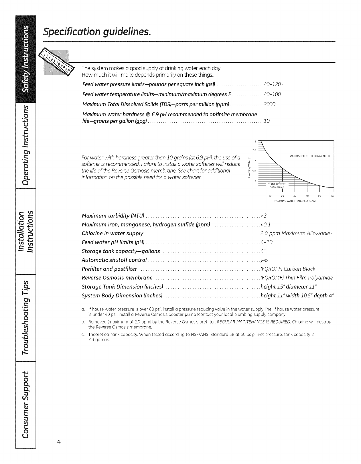
Forwater with hardness greater than !0 groins (at 6.9 pH),the use of a
softener is recommended. Failure to install a water softener willreduce
the life of the Reverse Osmosis membrane. See chart for additional
information on the possible need for a water softener.
_ 7
_ 65
8
75
WATERSOFTENERRECOMMENDED
6
Water Softener
I I I I
lO 20 30 40 50 60
INCOMING WATER HARDNESS (GPG)
Maximum turbidity (NTUJ ............................................... <2
Maximum iron, manganese, hydrogen sulfide (ppml .................... <0.!
Chlorine in water supply ............................................... 2.0 ppm Maximum Allowable b
Feed water pH limits (pHi ............................................... 4-10
Storage tank capacity-gallons ........................................ 4c
Automatic shutoff control ............................................. .yes
Prefilter and postfilter ................................................. (FQROPF)Carbon Block
Reverse Osmosis membrane ........................................... (FQROHF) Thin Film Polyamide
Storage Tank Dimension finches} ....................................... height !5" diameter !!"
System Body Dimension (inchesl ....................................... height !!" width !0.5" depth 4"
a. If housewater pressureisover80 psi,install a pressurereducingvalvein the water supply line.If housewater pressure
isunder 40 psi,installaReverseOsmosisbooster pump(contactyour local plumbingsupply company).
b. Removed(maximumof 2.0ppm) by the ReverseOsmosisprefilter. REGULARHAINTENANCEISREQUIRED. Chlorinewill destroy
the ReverseOsmosismembrane.
C.
Theoretical tank capacity. When tested according to NSF/ANSI Standard 58 at 50 psig inlet pressure, tank capacity is
2.3 gallons.
About the reverse osmosis system. GEApplio.ces.com
How the Reverse Osmosis System Works
ReverseOsmosisreducesTotal DissolvedSolids(TDS)and organic matter from water by diffusing it through u special
membrane (see Performance Data Sheet).The membrane separates minerals and impuritiesfrom the water and they are
flushed to the drain. Forthe reduction of the claims specified,see Performance Data Sheet. Highquality product water goes
directly to the drinking water faucet or to the storage tank. The system makes u good supply of drinking water each day. How
much it makes depends on the feed water supply pressure,temperature and quality.
The prefilter and postfilter are replaceable cartridges.Thecarbon prefilter reduceschlorine while alsofiltering sediments.
The postfilter reduces any other undesirabletastes and odors beforeyou usethe water.
Thesystem includesan electronic faucet assemblywith a prefilter and postfilter change reminder.When six months have
passed,a flashing light will remind you to change the two filters.
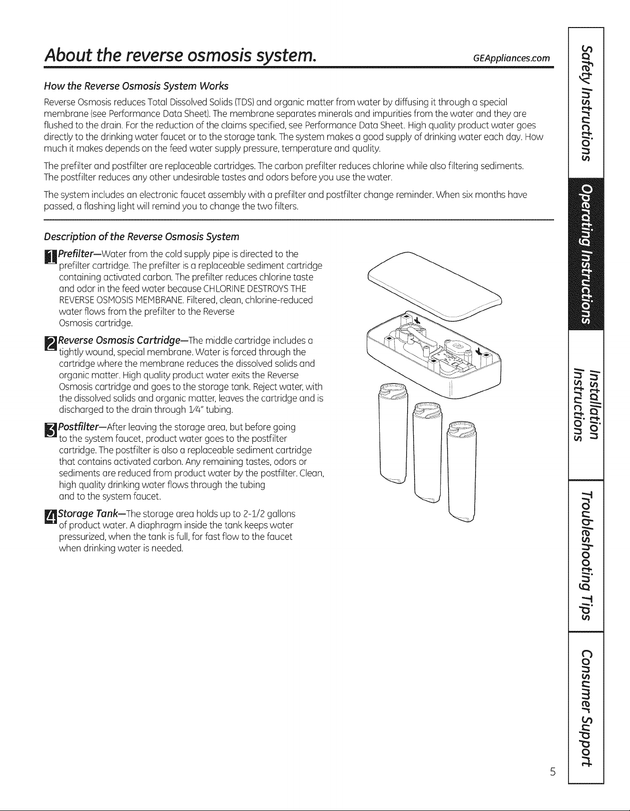
Description of the Reverse Osmosis System
HPrefilter-water from the cold supply pipe isdirected to the
prefilter cartridge. The prefilter isa replaceable sediment cartridge
containing activated carbon.The prefilter reduces chlorine taste
and odor in the feed water becauseCHLORINEDESTROYSTHE
REVERSEOSMOSISMEHBRANEFiltered,clean, chlorine-reduced
water flows from the prefilter to the Reverse
Osmosiscartridge.
_-_Reverse Osmosis Cartridge--The middle cartridge includes a
tightly wound, special membrane. Water isforced through the
cartridge where the membrane reducesthe dissolved solidsand
organic matter. High quality product water exits the Reverse
Osmosiscartridge and goesto the storage tank. Rejectwater,with
the dissolvedsolids and organic matter, leavesthe cartridge and is
discharged to the drain through !/4" tubing.
[]Postfilter--After leaving the storage area, but before going
to the system faucet, product water goes to the postfilter
cartridge.The postfilter is also a replaceable sediment cartridge
that contains activated carbon. Any remaining tastes, odors or
sediments are reduced from product water bythe posffilter. Clean,
high quality drinking water flows through the tubing
and to the system faucet.
_/'_Storuge Tunk--The storage area holdsup to 2-1/2 gallons
of product water. A diaphragm insidethe tank keepswater
pressurized,when the tank is full, for fast flow to the faucet
when drinking water is needed.
5
About the reverse osmosissystem.
_lJCheck Valve--The check valvepreventsa backward flow of product water from the storagetank. Abackward flow could
cause the ReverseOsmosismembrane to rupture.
[]Automatic Shutoff Assembly--To conservewater,the drinking water systemhasan automatic shutoff.Whenthe storagetank
hasfilled to capacityand the drinkingwater faucet isclosed,pressureclosesthe shutoff.Waterflow tothe ReverseOsmosis
housingisshut off untildrinkingwater is used again,and pressuredropsinthe ReverseOsmosissystem.
V_Flow Control--The flow control regulatesthe flow of water through the ReverseOsmosiscartridgeat the required rate to
producehigh quality water. Thecontrol is located inthe 1/4" drain lineexiting off the manifold.
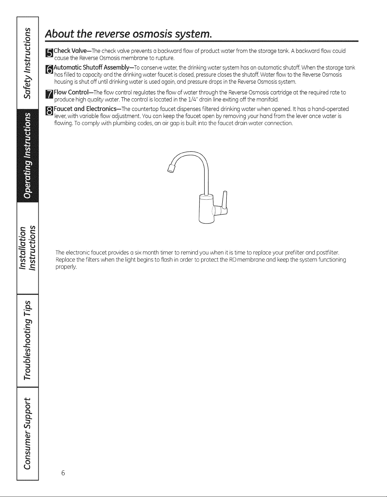
_JFaucet and Electronics--The countertop faucet dispensesfiltered drinking water when opened. It hasa hand-operated
lever,with variable flow adjustment. Youcan keepthe faucet open byremoving your hand from the leveroncewater is
flowing.To comply with plumbing codes,an airgap is built into the faucet drainwater connection.
Theelectronic faucet provides a six month timer to remind you when it istime to replaceyour prefilter and postfilter.
Replacethe filters when the light beginsto flash in order to protect the ROmembrane and keepthe system functioning
properly.
Installatio
ReverseOsmosis Filtration System
I str ct"
i_ uestions? Call 800.GE.CARES {800.432.2737} or visit our Website at: GEAppliances.com
In Canada, call 1.800.561.3344 or visit www.GEAppliances.ca
S
Models P×RQ15RBL and PNRQ15RBL
WARNING: Read entire manual. Failure to follow all guides and rules could cause
personal injury or property damage.
, Check with your state and/or local public works department for plumbing codes. You must follow their
guides as you install the Water Filtration system.
NOTE: Failure to comply with these installation instructions will void the product warranty, and the
installer will be responsible for any service, repair or damages caused thereby.
TOOLS AND MATERIALS REQUIRED FOR
INSTALLATION
, Electric drill and 1-1/4" Drill Bit (type as required)
if mounting is needed for faucet
, Two (2) Adjustable Wrenches
, 1/16" Drill Bit (optional for pilot holes)
, Tape Measure
, Phillips and Flat Blade Screwdrivers
, Utility Knife
, If your main water line is a rigid pipe,
you will require a compression fitting
and possibly other plumbing hardware
to complete the installation.
BEFORE BEGINNING INSTALLATION
Read these instructions completely
and carefully.
. IMPORTANT - Savetheseinstructions
for local inspector's use.
" IMPORTANT - Observe all governing
codes and ordinances.
, Note to Installer- Be sure to leave these
instructions with the Consumer.
, Note to Consumer - Keep these instructions for
future reference.
, Proper installation is the responsibility
of the installer.
i
IMPORTANT - To avoid damaging the sink,
consulta qualifiedplumber orinstallerfordrilling
procedures.Specialdrillbitsmay be needed for
porcelainor stainlesssteel.
CONTENTS INCLUDED
WITH PRODUCT
Reverse Osmosis Assembly and Tubing
Product Literature (Owner's Manual and
Installation Instructions)
Performance Data Sheet
Feed Water Adapter
Faucet Assembly with Electronic Base Monitor
and Tubing
Storage Tank
Drain Line Adapter
, Product failure due to improper installation is not
covered under the Warranty.
, A shutoff valve must be available or added near
the installation point.
Installation Instructions
Things to Check Before Beginning Installation
ROproduct water faucet mounted through sink or countertop
5/8" drain tube {block/
Disposer
Feed water adopter
1/4"
/yellow bondedl
t
15"
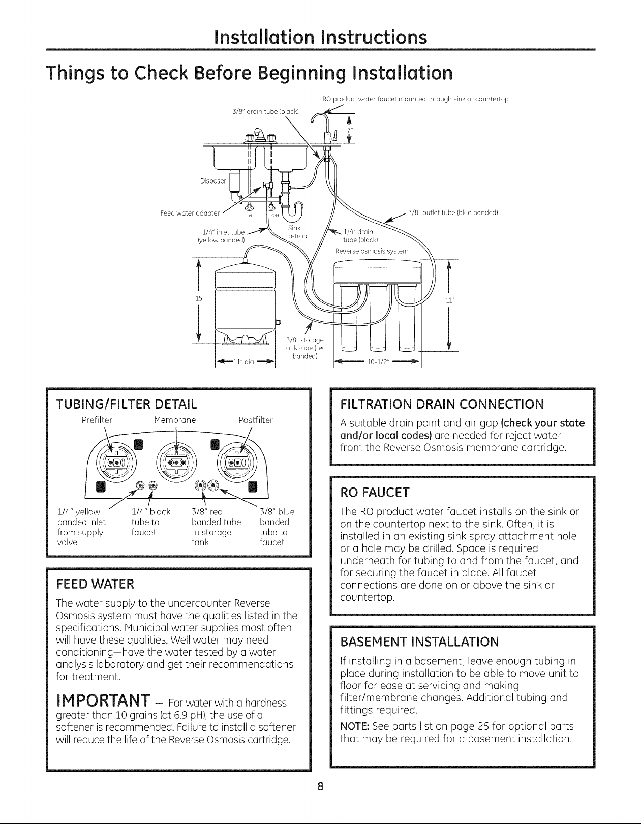
TUBING/FILTER DETAIL
Prefilter Membrane Postfilter
3/8" storage
tunk tube (red
bonded)
3/8" outlet tube (blue bonded}
l
11"
lO_l/2,,=====-tl_
FILTRATION DRAIN CONNECTION
A suitable drain point and air gap Icheck your state
and/or local codes} ore needed for reject water
from the Reverse Osmosis membrane cartridge.
RO FAUCET
1/4" yellow 1/4" black 3/8" red 3/8" blue
banded inlet tube to banded tube banded
from supply faucet to storage tube to
valve tank faucet
FEED WATER
The water supply to the undercounter Reverse
Osmosis system must have the qualities listed in the
specifications. Municipal water supplies most often
will have these qualities. Well water may need
conditioning-have the water tested by a water
analysis laboratory and get their recommendations
for treatment.
IM PORTANT - Forwaterwitha hardness
greaterthan i0 grains(at6.9pH),theuse ofa
softenerisrecommended. Failureto installa softener
willreducethelifeofthe ReverseOsmosis cartridge.
The RO product water faucet installs on the sink or
on the countertop next to the sink. Often, it is
installed in an existing sink spray attachment hole
or o hole may be drilled. Space is required
underneath for tubing to and from the faucet, and
for securing the faucet in place. All faucet
connections are done on or above the sink or
countertop.
BASEMENT INSTALLATION
If installing in a basement, leave enough tubing in
place during installation to be able to move unit to
floor for ease at servicing and making
filter/membrane changes. Additional tubing and
fittings required.
NOTE: See parts list on page 25 for optional parts
that may be required for a basement installation.
8
Installation Instructions
REVERSE OSMOSIS ASSEMBLY
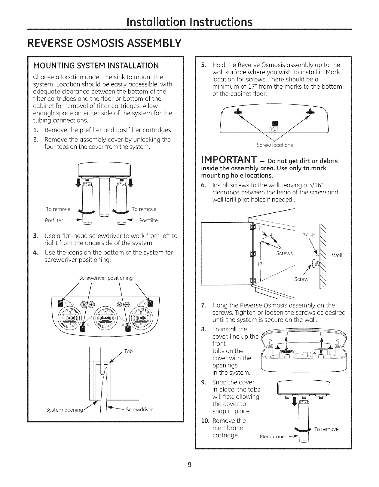
MOUNTING SYSTEM INSTALLATION
Choose a location under the sink to mount the
system. Location should be easily accessible, with
adequate clearance between the bottom of the
filter cartridges and the floor or bottom of the
cabinet for removal of filter cartridges. Allow
enough space on either side of the system for the
tubing connections.
1. Remove the prefilter and postfilter cartridges.
2. Remove the assembly cover by unlocking the
four tabs on the cover from the system.
To remove To remove
Prefilter _ _ Postfilter
3, Use a flat-head screwdriver to work from left to
right from the underside of the system.
4, Use the icons on the bottom of the system for
screwdriver positioning.
Screwdriver positioning
S,
Hold the Reverse Osmosis assembly up to the
wall surface where you wish to install it. Hark
location for screws. There should be a
minimum of 17" from the marks to the bottom
of the cabinet floor.
Screw locations
IMPORTANT - Do not get dirt or debris
inside the assembly area. Use only to mark
mounting hole locations.
6. Install screws to the wall, leaving a 3/16"
clearance between the head of the screw and
wall (drill pilot holes if needed).
\ Wall
\
\
\
\
\
\
\
\
System openinc Screwdriver
,
Hang the Reverse Osmosis assembly on the
screws. Tighten or loosen the screws as desired
until the system is secure on the wall.
,
To install the _._-_._...... .....
tabsfrontopen,ngscovercover,line up theonwiththethe _ ....:_lm- _--
in the system.
,
Snap the cover
in place; the tabs
will flex, allowing
the cover to
snap in place.
lO,
Remove the
membrane
cartridge.
Membrane
To remove
9
Installation Instructions
FEEDWATER SUPPLY
Check and comply with local plumbing codes as you plan, then install a cold feed water supply fitting.
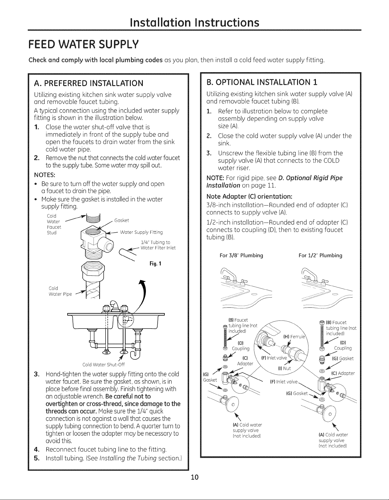
A. PREFERRED INSTALLATION
Utilizing existing kitchen sink water supply valve
and removable faucet tubing.
A typical connection using the included water supply
fitting is shown in the illustration below.
1. Closethe water shut-off valve that is
immediately in front of the supply tube and
open the faucets to drain water from the sink
cold water pipe.
2. Removethe nut that connectsthe coldwaterfaucet
to the supplytube.Somewater may spillout.
NOTES:
, Be sure to turn off the water supply and open
a faucet to drain the pipe.
, Make sure the gasket is installed in the water
supply fitting.
Cold
Water
Faucet
Stud
Gasket
Water Sup_,_,F_t_iLrlggto
-_ Water Filter Inlet
Fig,1
B. OPTIONAL INSTALLATION 1
Utilizing existing kitchen sink water supply valve (A)
and removable faucet tubing (B).
1. Refer to illustration below to complete
assembly depending on supply valve
size (A).
.
Close the cold water supply valve (A) under the
sink.
3.
Unscrew the flexible tubing line (B) from the
supply valve (A) that connects to the COLD
water riser.
NOTE: For rigid pipe, see D. Optional Rigid Pipe
Installation on page 11.
Note Adapter (C) orientation:
3/8-inch installation-Rounded end of adapter (C)
connects to supply valve (A).
1/2-inch installation-Rounded end of adapter (C)
connects to coupling (D), then to existing faucet
tubing (B).
For 318" Plumbing For 112" Plumbing
Cold Pipe
Water ,@_@,_ /_
f i
Cold Water Shut-Off
=
Hand-tighten the water supply fitting onto the cold
water faucet. Be sure the gasket, as shown, is in
place before final assembly. Finish tightening with
an adjustable wrench. Be careful not to
overtighten or cross-thread, since damage to the
threads can occur. Make sure the 1/4" quick
connection is not against a wall that causes the
supply tubing connection to bend. A quarter turn to
tighten or loosen the adapter may be necessary to
avoid this.
4. Reconnect faucet tubing line to the fitting.
5. Install tubing. (See Installing the Tubing section.)
Gasket
{G)__
{B)Faucet
tubing line (not
ed)
D)
Coupling
{c)
Adapter
\
{A) Cold water
supply valve
(not included)
{B} Faucet
tubing line (not
included)
ID)
oupling
i_ {G) Gasket
Q_dapter
IF} Inlet valve,
{G) Gasket.
\
{A} Cold water
supply valve
(not included)
10
Installation Instructions
FEEDWATER SUPPLY{cont.)
B. OPTIONAL INSTALLATION 1 {CONT.}
.
Assemble adapter (C)and coupling (D)as
shown in illustration on page 9, per your
configuration. Ensure that the gasket (G)is in
place before final assembly. Start installation
by hand, then finish tightening with adjustable
wrench. Be careful not to overtighten or
cross-thread since damage to threads may
occur.
S.
Hand-tighten assembled adapter (C)onto
supply valve (A) for the proper size installation.
Be sure gasket (G)is in place before final
assembly. Start installation by hand; then finish
tightening with an adjustable wrench.
Be careful not to overtighten or cross-thread
since damage to threads may occur.
.
Reconnect faucet tubing line (B) to top of
adapter (C).
7.
Cut wire ties on tubing coils, using care not to
damage tubes or parts if using a utility knife.
8.
Remove the 1/2" nut (I)and ferrule (H) from end
of inlet valve. Using the yellow banded tubing
provided, place the nut (I)and ferrule (H) onto
the tubing and install onto inlet valve (F) as
shown at left. Tighten with adjustable wrench.
Be careful not to overtighten or cross-thread
since damage to threads may occur.
NOTE: Inspect the ends of the tubing prior
to installation to be sure there are no imperfections
and that the end of the tubing is cut square. It may
be necessary to cut the tubing again.
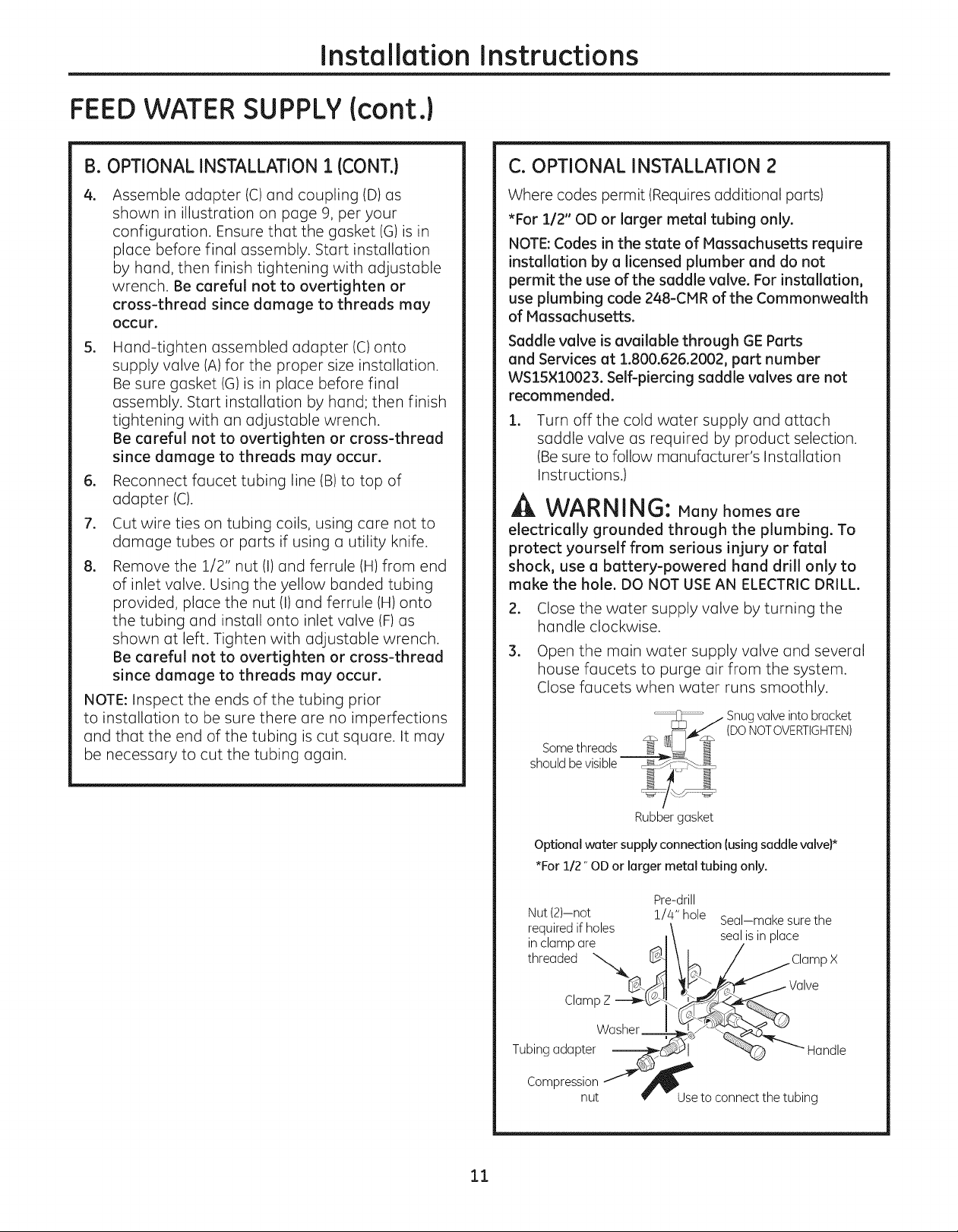
C. OPTIONAL INSTALLATION 2
Where codes permit (Requires additional parts)
*For 1/2" OD or larger metal tubing only.
NOTE:Codes in the state of Massachusetts require
installation by a licensed plumber and do not
permit the use of the saddle valve. For installation,
use plumbing code 248-CIVlR of the Commonwealth
of Massachusetts.
Saddle valve is available through GE Parts
and Services at 1.800.626.2002, part number
WS15×10023. Self-piercing saddle valves are not
recommended.
.
Turn off the cold water supply and attach
saddle valve as required by product selection.
(Be sure to follow manufacturer's Installation
Instructions.)
WARNING: Many homes are
electrically grounded through the plumbing. To
protect yourself from serious injury or fatal
shock, use a battery-powered hand drill only to
make the hole. DO NOT USEAN ELECTRIC DRILL.
.
Close the water supply valve by turning the
handle clockwise.
3.
Open the main water supply valve and several
house faucets to purge air from the system.
Close faucets when water runs smoothly.
Snugvalve into bracket
(DONOTOVERTIGHTEN)
Rubber gasket
Optional water supply connection (using saddle valve)*
*For 1/2" OD or larger metal tubing only.
Pre-drill
Nut (2)--not !/4" hole Seal-make surethe
required if holes \ ....
it_rCe_admePare_ I_J\l se,_'lSInplac_lamp x
ClampZ ---_ks>-_
TubingadapterWa_ _'- Handle
C°mpreSSntt __Use to connect the tubing
11
Installation Instructions
D. OPTIONAL RIGID PIPE INSTALLATION
For installation with rigid pipe between supply valve
and sink faucet.
Option 1
1. Remove pipe from supply valve and sink
faucet.
2. Obtain flexible pipe sized to your plumbing.
3. Install flexible pipe.
4. GO back to B. OPTIONAL INSTALLATION 1
section, step 4.
Option 2
1. Obtain compression fittings to fit rigid pipe.
2. Obtain any other fittings required to connect
compression fittings to adapter.
NOTE: Adapter has 1/2" and 3/8" internal and
external threads.
3. Remove pipe from supply valve.
4. Cut pipe to fit length of assembled fittings and
adapter.
5. Install compression fitting to pipe.
6. GO back to B. OPTIONAL INSTALLATION 1
section, step 4.
NOTE: Above described materials are not included
with the product.
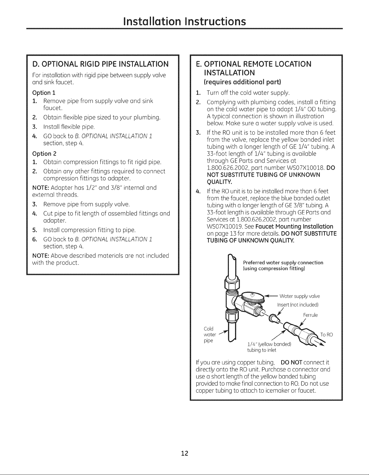
E. OPTIONAL REMOTE LOCATION
INSTALLATION
(requires additional part)
I.
Turn off the cold water supply.
2.
Complying with plumbing codes, install a fitting
on the cold water pipe to adapt 1/4" OD tubing.
A typical connection is shown in illustration
below. Make sure a water supply valve is used.
.
If the RO unit is to be installed more than 6 feet
from the valve, replace the yellow banded inlet
tubing with a longer length of GE 1/4" tubing. A
33-foot length of 1/4" tubing is available
through GE Parts and Services at
1.800.626.2002, part number WS07X10018. DO
NOT SUBSTITUTE TUBING OF UNKNOWN
QUALITY.
.
If the ROunit is to be installed more than 6 feet
from the faucet, replace the blue banded outlet
tubing with a longer length of GE 3/8" tubing. A
33-foot length is available through GEParts and
Services at 1.800.626.2002, part number
WS07X10019. See Faucet Mounting Installation
on page 13 for more details. DO NOT SUBSTITUTE
TUBING OF UNKNOWN QUALITY.
Preferred water supply connection
(using compression fitting}
Water supply valve
insert(not included)
Cold
water
pipe
1/4" (yellow banded) _'_"_
tubing to inlet
If you are using copper tubing, DO NOT connect it
directly onto the RO unit. Purchase a connector and
use a short length of the yellow banded tubing
provided to make final connection to RO.Do not use
copper tubing to attach to icemaker or faucet.
12

Installation Instructions
FEEDWATER SUPPLY{cont.)
INSTALLING THE TUBING TO TANK AND
FAUCET
.
Measure 3/4" from the end of each remaining
piece of tubing (faucet end and inlet end) and
mark with a pencil. (Check for roundness,
smoothness, cuts, nicks, flat spots and sharp
edges).
19 mm}
INCORRECT
.
Push the tubing firmly into each fitting on the
manifold until the line is flush with the fitting
collar. (if the tubing is removed, re-cut the end,
measure, mark and re-insert). Tubing must be
fully inserted to avoid leaks. To remove tubing:
depress and hold red or blue collet; pull tubing
out to remove.
Red or Blue Collet b_
(DONOTREMOVE) --e__
insertion line -_'_---- 3/4"--_
insert tubing ---_V]_,__
i
i
Engagement ',
3/4" -_
3/8" tubing) I
FLOW RESTRICTOR
REPLACEMENT PROCEDURE Icont.}
l. Remove drain line tubing by pushing up on the
drain line caller with one hand (11and
removing the drain line with the other hand (21.
. Once the drain line has been removed from the
system base, grasp the end of the flow
restrictor and pull it straight out from the tube*.
If the restrictor is difficult to remove by hand, a
pair of pliers may be used to grip the end of the
restrictor
to aid in removal from the tubing.
*In some instances, the restrictor may slide out of the drain
tubing as it is removed from the drain line port. If, after
removing the drain line as described in step !, the restrictor is
no longer in the end of the tubing, check the drain line port.
Remove the restrictor from the port and proceed to step 3.
. Take new restrictor and slide it back into the drain
tubing. Insert the restrictor by hand only. Do not
use pliers to insert. Make sure to insert restrictor
all the way into the tubing. Failure to do so could
result in improper operation of the ROsystem.
3. Pull out slightly on tubing to ensure a good
seal.
FLOW RESTRICTOR
REPLACEMENT PROCEDURE
Each time the Reverse Osmosis cartridge is
changed, you will need to replace the flow
restrictor in the drain line as well.
Be sure to wash your hands before handling inner
parts of the system.
13
.
Reinsert drain line tubing in system base. Tug
lightly on the tubing to ensure that the caller is
engaged and has a proper grip on the tubing.
FAUCET ASSEMBLY
Installation Instructions
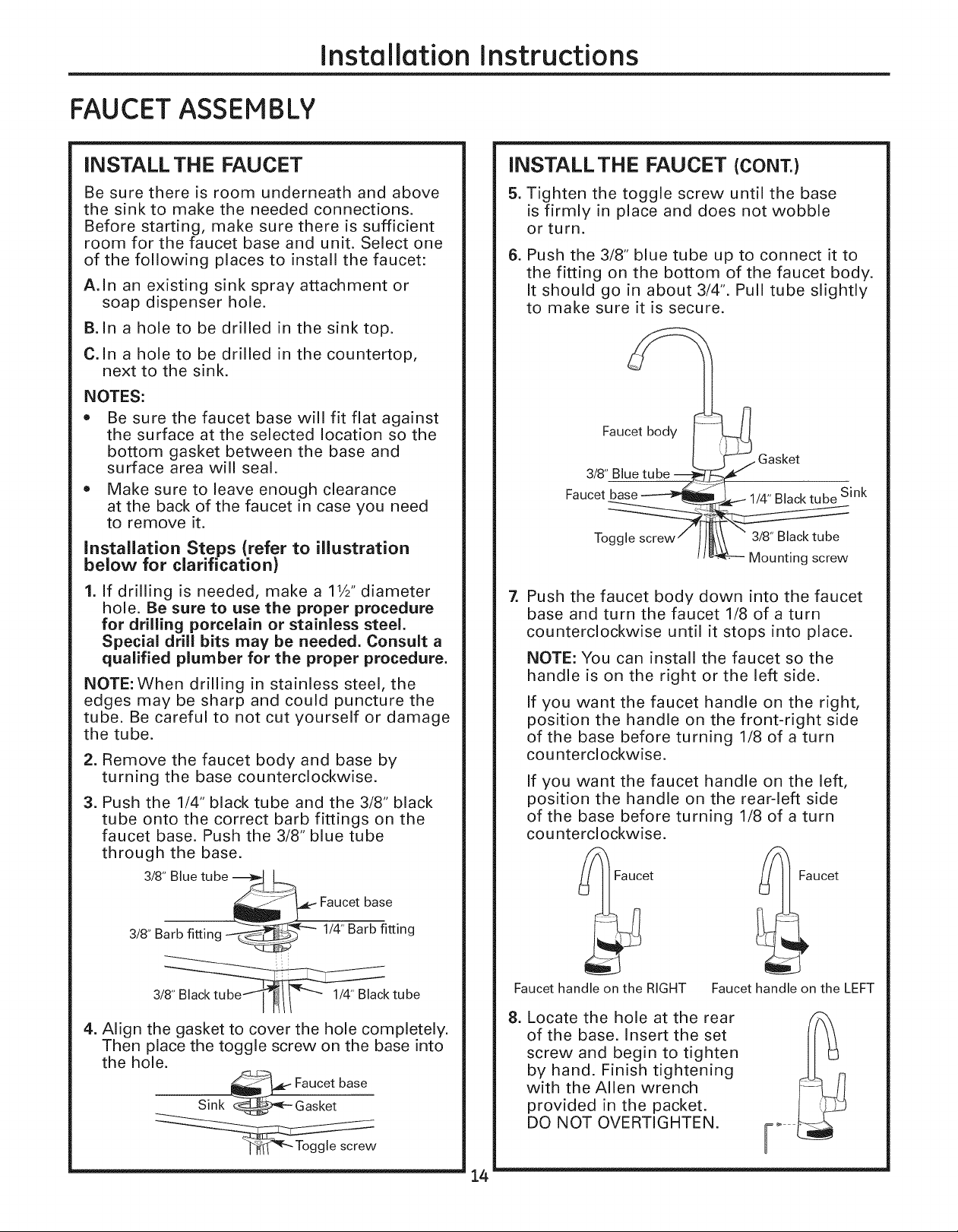
INSTALL THE FAUCET
Be sure there is room underneath and above
the sink to make the needed connections.
Before starting, make sure there is sufficient
room for the faucet base and unit. Select one
of the following places to install the faucet:
A. In an existing sink spray attachment or
soap dispenser hole.
B. In a hole to be drilled in the sink top.
C. In a hole to be drilled in the countertop,
next to the sink.
NOTES:
Be sure the faucet base will fit flat against
the surface at the selected location so the
bottom gasket between the base and
surface area will seal.
• Make sure to leave enough clearance
at the back of the faucet in case you need
to remove it.
Installation Steps (refer to illustration
below for clarification)
1. If drilling is needed, make a 11/2"diameter
hole. Be sure to use the proper procedure
for drilling porcelain or stainless steel,
Special drill bits may be needed. Consult a
qualified plumber for the proper procedure.
NOTE:When drilling in stainless steel, the
edges may be sharp and could puncture the
tube. Be careful to not cut yourself or damage
the tube.
2. Remove the faucet body and base by
turning the base counterclockwise.
3. Push the 1/4" black tube and the 3/8" black
tube onto the correct barb fittings on the
faucet base. Push the 3/8" blue tube
through the base.
3/8" Blue tube ---___
INSTALL THE FAUCET (CONT.)
5. Tighten the toggle screw until the base
is firmly in place and does not wobble
or turn.
6. Push the 3/8" blue tube up to connect it to
the fitting on the bottom of the faucet body.
It should go in about 3/4". Pull tube slightly
to make sure it is secure.
n
Faucet body _
Gasket
3/8" Blue
Faucet 1/4" Black tube Sink
Toggle 3/8" Black tube
Z
Push the faucet body down into the faucet
base and turn the faucet 1/8 of a turn
counterclockwise until it stops into place.
NOTE: You can install the faucet so the
handle is on the right or the left side.
If you want the faucet handle on the right,
position the handle on the front-right side
of the base before turning 1/8 of a turn
cou nterclockwise.
If you want the faucet handle on the left,
position the handle on the rear-left side
of the base before turning 1/8 of a turn
cou nterclockwise.
_ Faucet
>
Mounting screw
__ Faucet base
3/8" Barb fitting 1/4" Barb fitting
3/__k tube
4. Align the gasket to cover the hole completely.
Then place the toggle screw on the base into
the hole.
_ Faucet base
Sink _ Gasket
Faucet handle on the RIGHT
8. Locate the hole at the rear
of the base. Insert the set
screw and begin to tighten
by hand. Finish tightening
with the Allen wrench
provided in the packet.
DO NOT OVERTIGHTEN.
14
aucet
Faucet handle on the LEFT
Installation Instructions
FAUCETASSEMBLY {cont.)
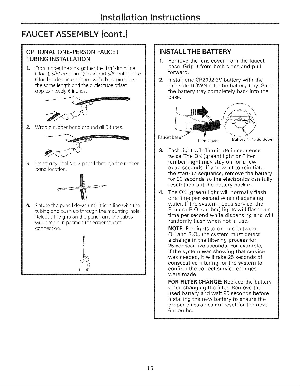
OPTIONAL ONE-PERSON FAUCET
TUBING INSTALLATION
I.
From under the sink, gather the 1/4" drain line
(black), 3/8" drain line (black) and 3/8" outlet tube
(blue banded)in one hand with the drain tubes
the same length and the outlet tube offset
approximately 6 inches.
2. Wrap a rubber band around all 3 tubes.
.
Insert a typical No. 2 pencil through the rubber
band location.
.
Rotate the pencil down until it is in line with the
tubing and push up through the mounting hole.
Release the grip on the pencil and the tubes
will remain in position for easier faucet
connection.
INSTALL THE BATTERY
=
Remove the lens cover from the faucet
base. Grip it from both sides and pull
forward.
=
Install one CR2032 3V battery with the
"+" side DOWN into the battery tray. Slide
the battery tray completely back into the
base.
Faucet base
=
Each light will illuminate in sequence
Lens cover
twice.The OK (green) light or Filter
(amber) light may stay on for a few
extra seconds. If you want to reinitiate
the start-up sequence, remove the battery
for 90 seconds so the electronics can fully
reset; then put the battery back in.
=
The OK (green) light will normally flash
one time per second when dispensing
water. If the system needs service, the
Filter or R.O. (amber) lights will flash one
time per second while dispensing and will
randomly flash when not in use.
NOTE: For lights to change between
OK and R.O., the system must detect
a change in the filtering process for
25 consecutive seconds. For example,
if the system was showing that service
was needed, it will take 25 seconds of
consecutive filtering for the system to
confirm the correct service changes
were made.
FOR FILTER CHANGE: Replace the battery_
when changing the filter. Remove the
used battery and wait 90 seconds before
installing the new battery to ensure the
proper electronics are reset for the next
6 months.
Battery "+"side down
15
Installation Instructions
FILTRATION DRAIN CONNECTION
Check and comply with local plumbing codes as you plan.
A CAUTION: The options detailed below are the ONLY approved installation
configurations. Do not use any drain saddle device.
NOTE: Failure to follow these Installation Instructions will void the warranty, and the installer will be
responsible for any service, repair or damages caused thereby.
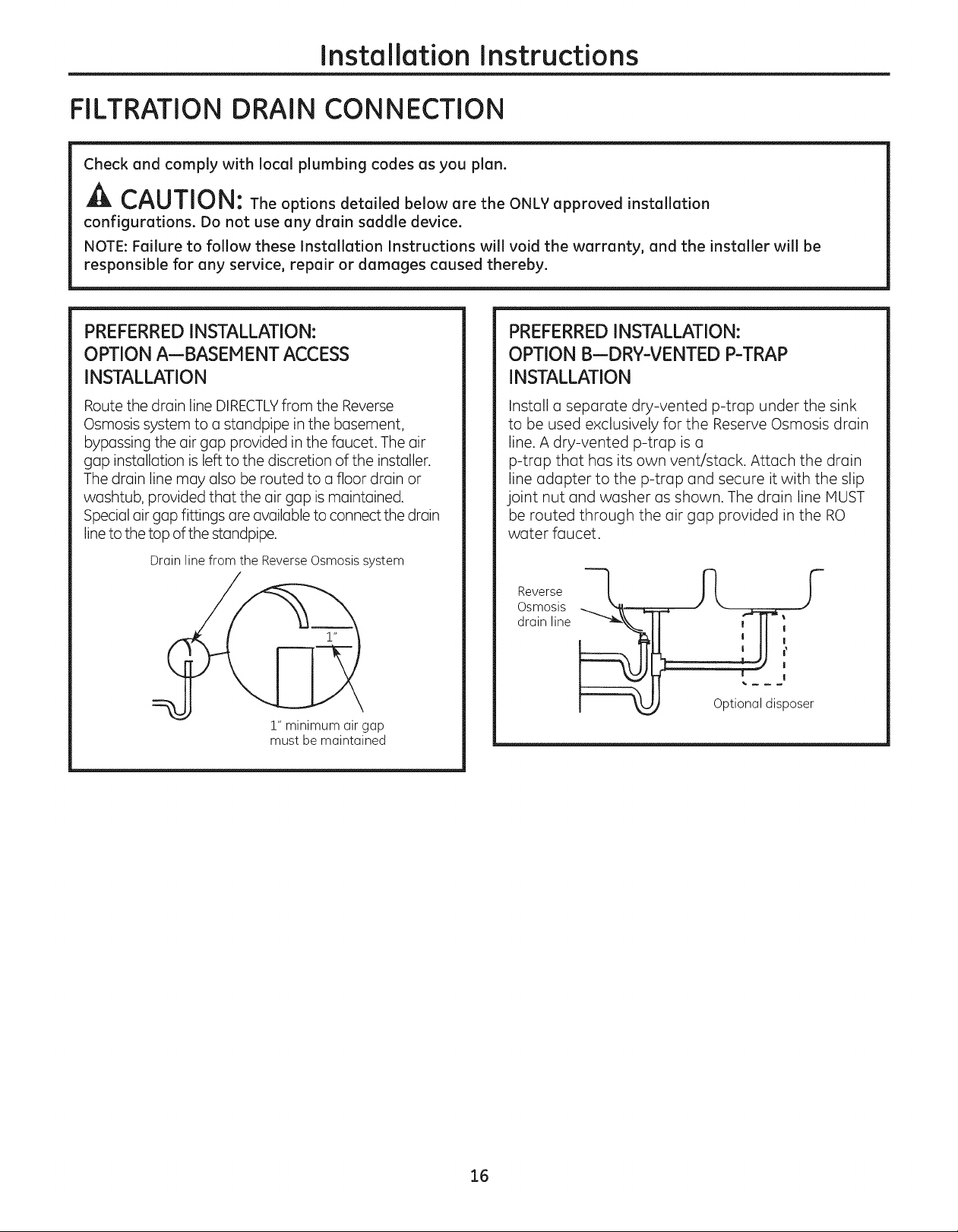
PREFERRED INSTALLATION:
OPTION A--BASEM ENT ACCESS
INSTALLATION
Route the drain line DIRECTLYfrom the Reverse
Osmosis system to a standpipe in the basement,
bypassing the air gap provided in the faucet. The air
gap installation is left to the discretion of the installer.
The drain line may also be routed to a floor drain or
washtub, provided that the air gap is maintained.
Special air gap fittings are available to connect the drain
line to the top of the standpipe.
Drain line from the Reverse Osmosis system
!" minimum air gap
must be maintained
PREFERREDINSTALLATION:
OPTION B--DRY-VENTED P-TRAP
INSTALLATION
Install a separate dry-vented p-trap under the sink
to be used exclusively for the Reserve Osmosis drain
line. A dry-vented p-trap is a
p-trap that has its own vent/stack. Attach the drain
line adapter to the p-trap and secure it with the slip
joint nut and washer as shown. The drain line MUST
be routed through the air gap provided in the RO
water faucet.
Reverse
Osmosis
drain line
Optional disposer
16
Installation Instructions
FiLTRATiON DRAIN CONNECTION (cont.)
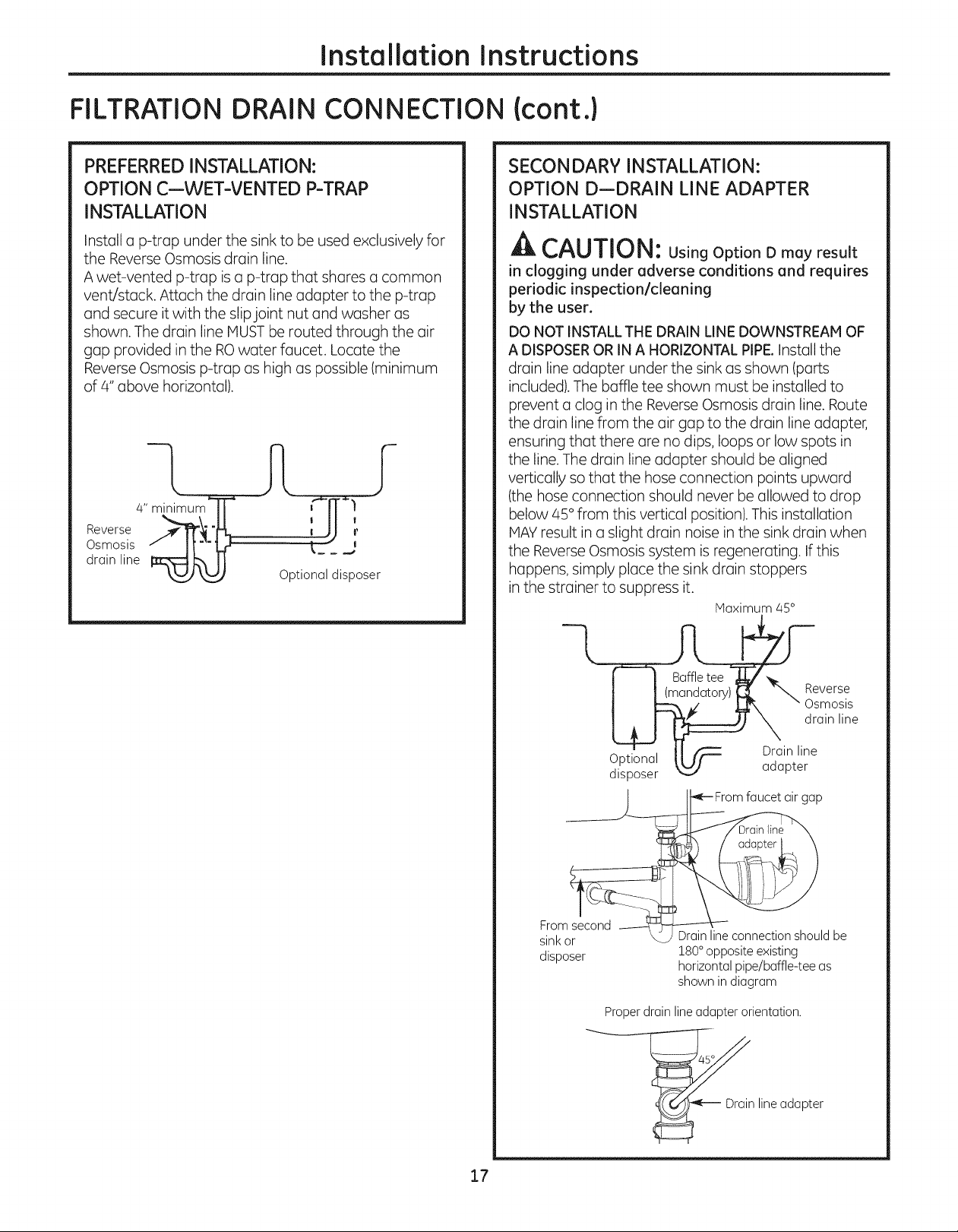
PREFERREDINSTALLATION:
OPTION C--WET-VENTED P-TRAP
INSTALLATION
Install a p-trap under the sink to be used exclusively for
the Reverse Osmosis drain line.
A wet-vented p-trap is a p-trap that shares a common
vent/stack. Attach the drain line adapter to the p-trap
and secure it with the slipjoint nut and washer as
shown. The drain line MUST be routed through the air
gap provided in the ROwater faucet. Locate the
Reverse Osmosis p-trap as high as possible (minimum
of 4" above horizontal).
-t
4" minimum" T
Reverse _--_ "lu_
Osmosis _" [ ["" W-
drain line
Optional disposer
SECONDARY INSTALLATION:
OPTION D--DRAIN LINE ADAPTER
INSTALLATION
A CAUTION: UsingOption D may result
in clogging under adverse conditions and requires
periodic inspection/cleaning
by the user.
DO NOT INSTALLTHE DRAIN LINE DOWNSTREAM OF
A DISPOSEROR IN A HORIZONTAL PIPE.Install the
drain line adapter under the sink as shown (parts
included). The baffle tee shown must be installed to
prevent a clog in the Reverse Osmosis drain line. Route
the drain line from the air gap to the drain line adapter,
ensuring that there are no dips, loops or low spots in
the line. The drain line adapter should be aligned
vertically so that the hose connection points upward
(the hose connection should never be allowed to drop
below 45° from this vertical position). This installation
HAY result in a slight drain noise in the sink drain when
the Reverse Osmosis system is regenerating. If this
happens, simply place the sink drain stoppers
in the strainer to suppress it.
Haximum 45°
_everse
I _ _ " _X " Osmosis
L_ _ 7 . drainline
.' , II _Druinline
up_lonal II/f _ .....
di'sposer _ aaap_er
From
sink or \
disposer
Properdrain lineadapter orientation.
•_-- From faucet air gap
Drain line connection should be
180°opposite existing
horizontal pipe/baffle-tee as
shown in diagram
45°
line adapter
17
Installation Instructions
STORAGE TANK AND STARTUP
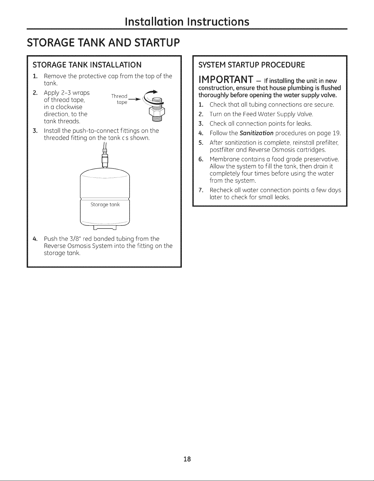
STORAGE TANK INSTALLATION
1. Remove the protective cap from the top of the
tank.
.
Apply 2-3 wraps
of thread tape,
in a clockwise
direction, to the
tank threads.
.
Install the push-to-connect fittings on the
threaded fitting on the tank cs shown.
Storage tank
Thread _
tape
SYSTEM STARTUP PROCEDURE
IMPORTANT - if installing the unit in new
construction, ensure that house plumbing is flushed
thoroughly before opening the water supply valve.
1. Check that all tubing connections are secure.
2. Turn on the Feed Water Supply Valve.
3. Check all connection points for leaks.
4. Follow the Sanitization procedures on page 19.
S.
After sanitization is complete, reinstall prefilter,
postfilter and Reverse Osmosis cartridges.
6.
Membrane contains a food grade preservative.
Allow the system to fill the tank, then drain it
completely four times before using the water
from the system.
7. Recheck all water connection points a few days
later to check for small leaks.
4. Push the 3/8" red banded tubing from the
Reverse Osmosis System into the fitting on the
storage tank.
18
Careand cleaningof the reverse osmosissystem. GEAppliances.com
Prefilter, Postfilter and Reverse Osmosis Membrane Cartridge Replacement Procedure
When the blue light in the faucet base flashes,
it is time to replace the prefilter and Dostfilter. This will
occur every 6 months.
Be sure to wash your hands before handling inner parts
of the system.
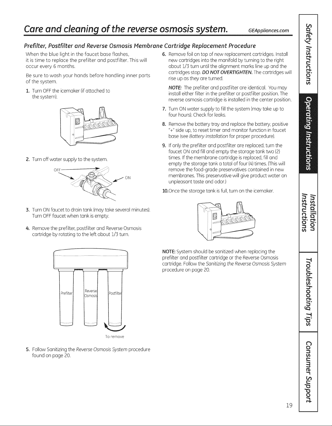
1. TurnOFFthe icemaker(ifattached to
the system).
2. Turnoff water supply to the system.
OFf _ -..- )
ON
6. Removefoil on top of new replacement cartridges. Install
new cartridges into the manifold by turning to the right
about 1/3 turn until the alignment marks line up and the
cartridges stop.DONOTOVERTIGHTEN.Thecartridges will
riseup as they are turned.
NOTE:Theprefilter and postfilter are identical. Vou may
install either filter in the prefilter or postfilter position.The
reverseosmosis cartridge isinstalled inthe center position.
7. Turn ONwater supply to fill the system (may take up to
four hours).Checkfor leaks.
8. Removethe battery tray and replacethe battery, positive
'%"side up,to reset timer and monitor function infaucet
base(seeBattery Installation for proper procedure).
.
If only the prefilter and postfilter are replaced,turn the
faucet ONand fill and empty the storage tank two (2)
times. Ifthe membrane cartridge isreplaced,fill and
empty the storage tank a total of four (4)times. (Thiswill
remove the food-grade preservativescontained in new
membranes. Thispreservative will give product water an
unpleasant taste and odor.)
lO.Oncethe storage tank isfull,turn on the icemaker.
3. TurnONfaucet to drain tank (may takeseveral minutes).
TurnOFFfaucet when tank is empty.
4. Removethe prefilter,postfilter and ReverseOsmosis
cartridge by rotating to the left about 1/5 turn.
m
To remove
5. Follow Sanitizingthe ReverseOsmosisSystemprocedure
found on page 20.
NOTE:Systemshould be sanitized when replacing the
prefilter and postfilter cartridge or the ReverseOsmosis
cartridge. Followthe Sanitizing theReverseOsmosisSystem
procedure on page 20.
19
Care and cleaning ofthe reverse osmosissystem.
Sanitizing the Reverse Osmosis System
Sanitize upon installation of the Reverse Osmosis system
and after servicing inner parts, including replacement of
prefilter, postfilter and the membrane cartridge.
Besure to wash your hands before handling inner parts
of the system.
IMPORTANT --Beforesanitizing, besure
to remove all cartridges. Chlorine will destroy the Reverse
Osmosismembrane cartridge.
1. Followsteps i through 4 under Prefi/ter,Postfi/ter end
ReverseOsmosisMembraneCartridge Replacement
Procedure.
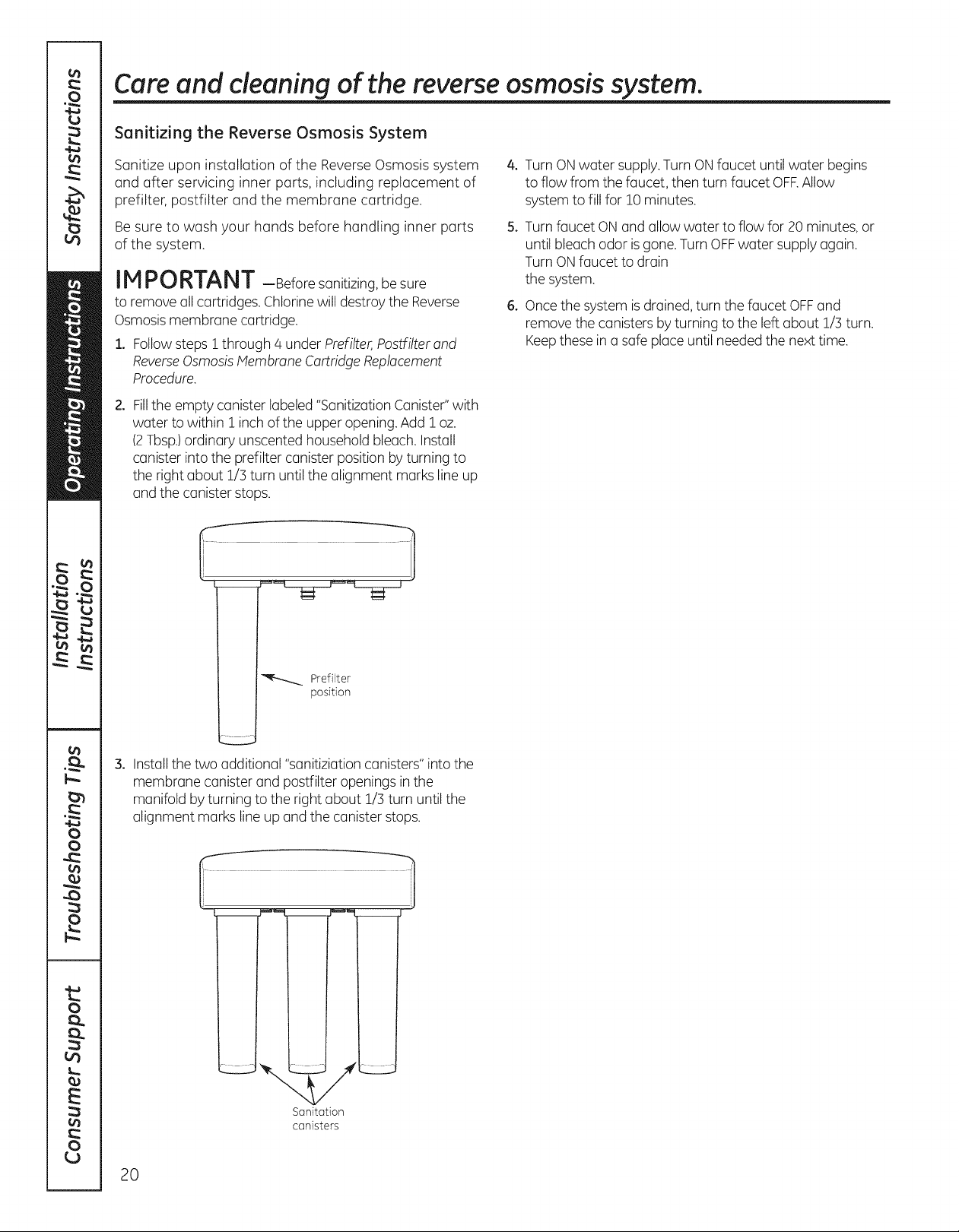
2. Fillthe empty canister labeled "SanitizationCanister"with
water to within 1 inchof the upper opening.Add 1oz.
(2Tbsp.)ordinary unscented household bleach.Install
canister into the prefilter canister position by turning to
the right about !/3 turn until the alignment marks line up
and the canister stops.
4. TurnONwater supply.Turn ON faucet until water begins
to flow from the faucet, then turn faucet OFF.Allow
system to fill for 10 minutes.
5. Turnfaucet ONand allow water to flow for 20 minutes, or
until bleach odor is gone. Turn OFFwater supply again.
TurnONfaucet to drain
the system.
6. Oncethe system is drained,turn the faucet OFFand
remove the canisters by turning to the left about 1/3 turn.
Keepthese ina safe placeuntil needed the nexttime.
'_--_...._ Prefi4ter
21.Installthe two additional "sanitiziationcanisters" into the
membrane canister and postfilter openings inthe
manifold by turning to the right about 1/3 turn until the
alignment marks line up and the canister stops.
position
J
Sanitation
canisters
20
Careand cleaning of the reverse osmosissystem. GEAppliances.com
To obtain replacement filters, call toll-free GEAppliance Parts at 800.626.2002 (U.S.),
800.663.6060 (Canada-English), 800.361.3869 (Canada-French), or visit the store where
you purchased your reverse osmosis system.
Prefilter/Postfilter Cartridge Replacement FQROPF Carbon Block
Reverse Osmosis Cartridge Replacement FQROMF Thin Film Polyamide
WARNING: To reduce the risk of physical injury:
Depressurize system as shown in manual prior to catridge removal.
The Water Test Kit
Toobtain an independent laboratory water test kit, please call Legend Technical Services at
1.800.826.8553 ext. 47 and leave your contact details. They will contact you to find out what water tests
you are interested in, and inform you of the cost of the testing. You will then receive a kit that will include
all necessary tests to properly indicate the performance level of your system. Product water should be
tested a minimum of every six months.
NOTE:When the TDS reduction of the system falls below 75%, it istime to replace the reverse osmosis
cartridge in addition to the prefilter and postfilter.
21
Before you call for service...
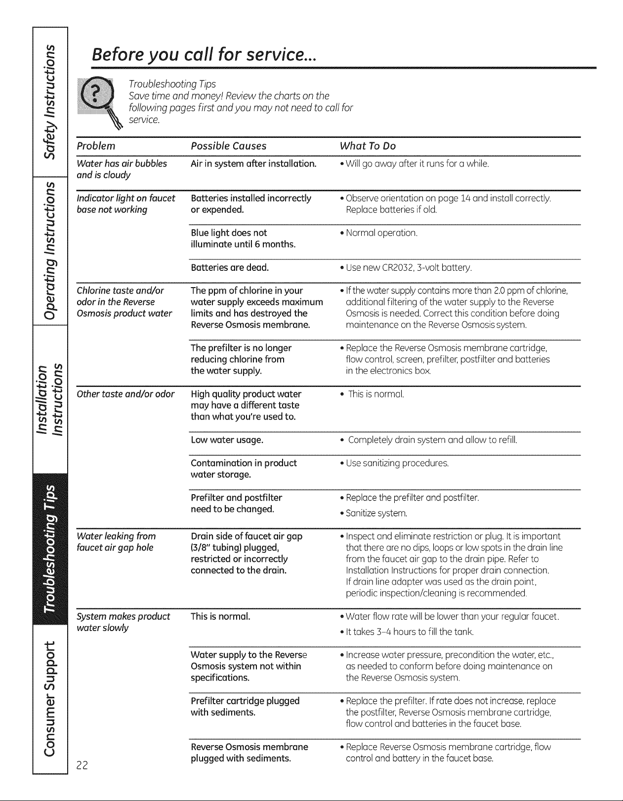
Troubleshooting Tips
Save time and money! Review the charts on the
following pages first and you may not need to call for
service.
Problem Possible Causes What To Do
Water has air bubbles Air in system after installation. . Will go away after it runs for a while.
and is cloudy
Indicator light on faucet Batteries installed incorrectly . Observeorientation on page 14 and install correctly.
base not working or expended. Replacebatteries if old.
Blue light does not . Normal operation.
illuminate until 6 months.
Batteries are dead. . Usenew CR2032,3-volt battery.
Chlorine taste and/or
odor in the Reverse
Osmosis product water
Other taste and/or odor
Water leaking from
faucet air gap hole
The ppm of chlorine in your
water supply exceeds maximum
limits and has destroyed the
ReverseOsmosis membrane.
The prefilter is no longer
reducing chlorine from
the water supply.
High quality product water
may have a different taste
than what you're used to.
Low water usage. . Completely drain system and allow to refill.
Contamination in product . Usesanitizing procedures.
water storage.
Prefilter and postfilter • Replacethe prefilter andpostfilter.
need to be changed. • Sanitizesystem.
Drain side of faucet air gap
(318"tubing} plugged,
restricted or incorrectly
connected to the drain.
• Ifthe water supplycontains more than 2.0ppmof chlorine,
additional filtering of the water supply to the Reverse
Osmosisisneeded.Correctthis condition before doing
maintenance on the ReverseOsmosissystem.
. Replacethe ReverseOsmosismembrane cartridge,
flow control, screen, prefilter, postfilter and batteries
in the electronics box.
. Thisisnormal.
. Inspect and eliminate restriction or plug. It is important
that there are no dips, loopsor lowspots inthe drain line
from the faucet air gap to the drain pipe.Referto
Installation Instructions for proper drain connection.
If drain line adapter was usedasthe drain point,
periodic inspection/cleaning isrecommended.
System makes product
water slowly
22
This is normal.
Water supply to the Reverse
Osmosis system not within
specifications.
Prefilter cartridge plugged
with sediments.
ReverseOsmosis membrane
plugged with sediments.
. Water flow rate will be lower than your regular faucet.
. It takes 3-4 hoursto fill the tank.
. Increasewater pressure,precondition the water, etc.,
asneeded to conform before doing maintenance on
the ReverseOsmosissystem.
. Replacethe prefilter. If rate doesnot increase,replace
the postfilter,ReverseOsmosismembrane cartridge,
flow control and batteries in the faucet base.
. ReplaceReverseOsmosismembrane cartridge, flow
control and battery in the faucet base.
Before you call for service...
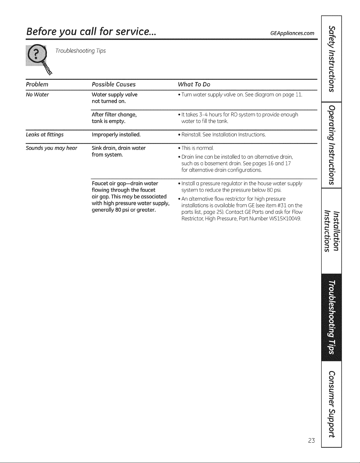
Troubleshooting Tips
Problem Possible Causes What To Do
No Water Water supply valve . Turn water supply valve on. See diagram on page 11.
not turned on.
After filter change, . Ittakes 3-4 hours for RO system to provide enough
tank is empty, water to fillthe tank.
Leaks at fittings Improperly installed. . Reinstall.See InstallationInstructions.
Sounds you may hear Sink drain, drain water . This is normal.
from system.
. Drain linecan be installedto an alternative drain,
such as a basement drain. Seepages 16 and 17
for alternative drain configurations.
GEAppliances.com
Faucet air gap-drain water
flowing through the faucet
air gap. This may be associated
with high pressure water supply,
generally 80 psi or greater.
. Installa pressure regulator in the house water supply
systemto reduce the pressure below 80 psi.
An alternative flow restrictor for high pressure
installations is available from GE(seeitem #51 on the
parts list, page 25).Contact GEPartsand askfor Flow
Restrictor,High Pressure,Part Number WS15X10049.
23
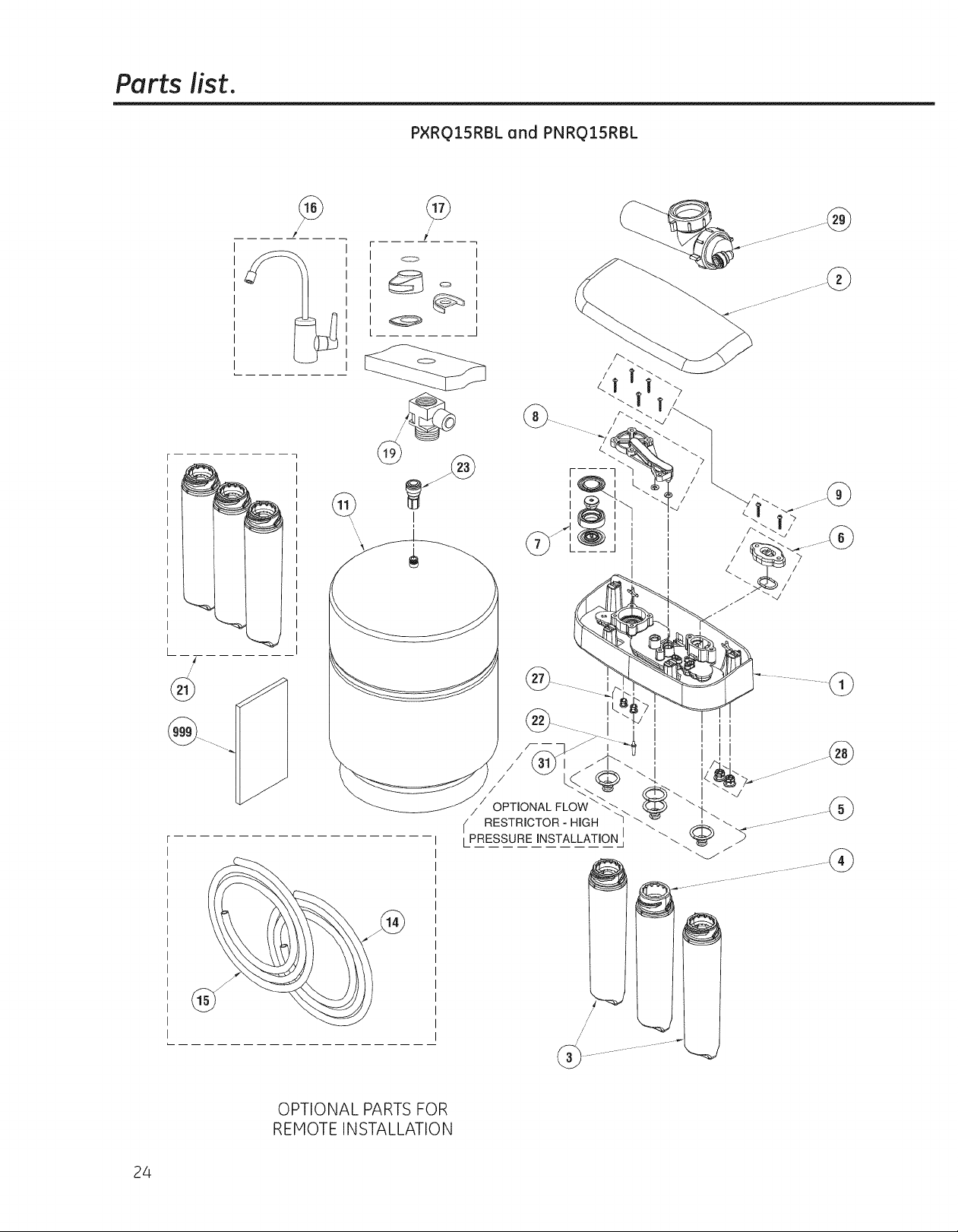
Parts list.
@
PXRQ15RBL and PNRQ15RBL
@
/'
#
Q
24
®
OPTIONAL PARTS FOR
REMOTE INSTALLATION
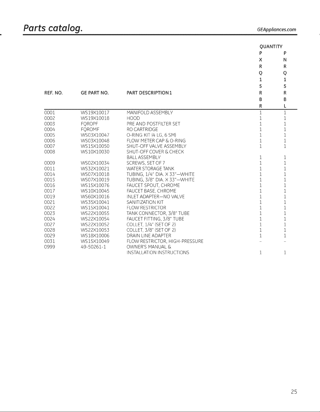
Parts catalog. GEApp,on . om
QUANTITY
P P
X N
R R
Q Q
1 1
5 5
REF. NO.
0001
0002
0003
0004
0005
0006
0007
0008
0009
0011
0014
0015
0016
0017
0019
0021
0022
0023
0024
0027
0028
0029
0031
0999
GE PART NO. PART DESCRIPTION 1
WS19X10017
WS19X10018
FQROPF
FQROMF
WSO3X10047
WSO3X10048
WS15X10050
WSIOXIO030
WSO2X10034
WS32X10021
WSO7X10018
WSO7X10019
WS15X10076
WS10X10045
WS60X10016
WS35X10041
WS15X10041
WS22X10055
WS22X10054
WS22X10052
WS22X10053
WS18X10006
WS15X10049
49-50261-1
MANIFOLD ASSEMBLY
HOOD
PREAND POSTFILTERSET
ROCARTRIDGE
O-RING KIT (4 LG, 6 SM)
FLOW METER CAP & O-RING
SHUT-OFF VALVE ASSEMBLY
SHUT-OFF COVER & CHECK
BALLASSEM BLY
SCREWS, SETOF 7
WATER STORAGETANK
TUBING, 1/4" DIA. X 33"--WHITE
TUBING, 3/8" DIA. X 33"--WHITE
FAUCET SPOUT, CHROME
FAUCET BASE, CHROME
INLET ADAPTER--NO VALVE
SANITIZATION KIT
FLOW RESTRICTOR
TANK CONNECTOR, 3/8" TUBE
FAUCET FITTING, 3/8" TUBE
COLLET, 1/4" (SETOF 2)
COLLET, 3/8" (SETOF 2)
DRAIN LINE ADAPTER
FLOW RESTRICTOR, HIGH-PRESSURE
OWNER'S MANUAL &
INSTALLATION INSTRUCTIONS
R R
B B
R L
1 1
1 1
1 1
1 1
1 1
1 1
1 1
1 1
1 1
1 1
1 1
1 1
1 1
1 1
1 1
1 1
! !
1 1
1 1
1 1
1 1
1 1
1 1
25
 Loading...