

GE Entelliguard TU Conversion Kit, MicroVersaTrip Plus Conversion Kit, PM Conversion Kit Installation Instructions Manual
Page 1
INTRODUCTION
GE Conversion Kits are designed for upgrading existing Allis
Chalmers®, Siemens/Allis®, and Siemens® low-voltage
power circuit breakers, rather than replacing the entire breaker.
The Conversion Kits include Entelliguard TU™,
MicroVersaTrip Plus™ or MicroVersaTrip PM™ Trip Units,
the latest technological advance in GE trip systems.
Entelliguard, MicroVersaTrip Plus and MicroVersaTrip P
Conversion Kits are designed and tested to conform to ANSI
Standard C37.59, allowing the retrofitter to properly install the
kit and acceptance test the breaker.
This publication covers installation of Entelliguard,
MicroVersaTrip Plus and MicroVersaTrip PM Conversion Kits
on Allis Chalmers®, Siemens/Allis®, and Siemens® LA-4000
low-voltage power circuit breakers. Each Conversion Kit
contains all the components needed to convert from the existing
trip system.
DEH40015
Installation Instructions .
R01
Entelliguard TU™, MicroVersaTrip
Plus™ and PM™ Conversion Kits
for Allis Chalmers®, Siemens/Allis® LA-4000-Blue
Low-Voltage Power Circuit Breakers
Page 2

1
TABLE OF CONTENTS
Section 1. General Information ............................................................................................................ Page 3
Section 2. Before Installation ................................................................................................................ Page 3
Section 3. Breaker Preparation ............................................................................................................ Page 4
Section 4. Installing the Conversion Kit .............................................................................................. Page 5
Installing Flux Shifter Reset Bracket ............................................................................................................ Page 6
Installing ththe Trip Unit Wiring Harness ..................................................................................................... Page 7
Installing the Trip Unit Mounting Bracket .................................................................................................... Page 9
Installing the Current Sensors ..................................................................................................................... Page 10
Installing the Communications Harness ...................................................................................................... Page 11
Section 5. Installing the Trip Unit ...................................................................................................... Page 11
Section 6. Four-Wire Ground Fault Option ...................................................................................... Page 12
Section 7. Testing and Trouble-shooting ........................................................................................... Page 13
Testing ........................................................................................................................................................ Pages 13
Trouble-Shooting ........................................................................................................................................ Page 14
Nuisance Tripping on Ground Fault-Equipped Breakers .............................................................. Page 14
Page 3

2
LIST OF FIGURES
1. Primary disconnects removed from the bottom studs. ............................................................................................. Page 4
2. Components supplied with the conversion kit. ........................................................................................................ Page 5
3. Old and New Reset Assembly. ................................................................................................................................ Page 6
4. Installed Reset Assembly. ........................................................................................................................................ Page 6
5. Flux shifter mounting location. ................................................................................................................................ Page 6
6. Flux shifter mounting.. ............................................................................................................................................. Page 6
7. Flux shifter mounting. .............................................................................................................................................. Page 6
8. Installing Reset Link. ............................................................................................................................................... Page 6
9. 36-pin trip unit connector ......................................................................................................................................... Page 7
10. 36-pin connector adapter bracket ............................................................................................................................. Page 7
11. Adapter bracket locking tabs.................................................................................................................................... Page 8
12. Installing the push nuts ono the guide pins. ............................................................................................................. Page 8
13. Locking tabs on mounting plate.. ............................................................................................................................. Page 8
14. Trip unit bracket mounting. ..................................................................................................................................... Page 9
15. Securing trip unit bracket. ........................................................................................................................................ Page 9
16. Position of current sensors. .................................................................................................................................... Page 10
17. Installing current sensors ....................................................................................................................................... Page 10
18. Installing wire harness. .......................................................................................................................................... Page 10
19. Caution label to be applied to the breaker and compartment door... ...................................................................... Page 11
20. Trip unit installed on the breaker. .......................................................................................................................... Page 11
21. Neutral sensor outline for 3000A through 4000A breakers ................................................................................... Page 13
Page 4

3
SECTION 1. GENERAL
INFORMATION
GE Conversion Kit installation is straightforward, but does
require careful workmanship and attention to these
instructions. Familiarity with the breaker is highly desirable.
The general approach is to first remove the existing trip
devices from the breaker, then install the Entelliguard,
MicroVersaTrip Plus and MicroVersaTrip PM kit components.
Following this procedure, the converted breaker is performance
tested before it is returned to service.
The majority of trip unit kit installations do not require any
customized assembly work. However, some conversions may
involve unusual mounting conditions or accessory
combinations that require minor modifications and/or
relocation of components. In most instances, this
supplementary work can be done on site.
In preparation for the conversion, the installer should verify
that the appropriate current sensors and trip unit have been
furnished. Whenever a ground-fault trip element is installed on
a breaker with a four-wire system, an associated neutral sensor
(CT) is required for separate mounting in the equipment.
Ensure that retrofitted breakers are applied within their shortcircuit ratings. For example, when the trip elements of the
breaker are to be changed from long-time instantaneous to
long-time short-time, the short-time rating will govern the
application.
As a service-related consideration, the installation of a
Entelliguard, MicroVersaTrip Plus and MicroVersaTrip PM kit
provides an excellent opportunity to perform normal
maintenance on the breaker. Such procedures are described in
the installation and maintenance manuals supplied with the
breaker and equipment.
SECTION 2. BEFORE INSTALLATION
Before starting any work, turn off and lock out all power
sources leading to the breaker, both primary and secondary.
Remove the breaker to a clean, well-lighted work area.
WARNING: Low-voltage power circuit breakers use highspeed, stored-energy spring operating mechanisms. The
breakers and their enclosures contain interlocks and safety
features intended to provide safe, proper operating sequences.
For maximum personnel protection during installation,
operation, and maintenance of these breakers, the following
procedures must be followed. Failure to follow these
procedures may result in personal injury or property damage.
• Only qualified persons, as defined in the National
Electrical Code, who are familiar with the installation and
maintenance of low-voltage power circuit breakers and
switchgear assemblies, should perform any work on these
breakers.
• Completely read and understand all instructions before
attempting any breaker installation, operation,
maintenance, or modification.
• Turn off and lock out the power source feeding the
breaker before attempting any installation, maintenance,
or modification. Follow all lock-out and tag-out rules of
the National Electrical Code and all other applicable
codes.
• Do not work on a closed breaker or a breaker with the
closing springs charged. Trip the breaker OPEN and be
sure the stored-energy springs are discharged, thus
eliminating the possibility that the breaker may trip open
or the closing springs discharge and cause injury.
• Trip the breaker OPEN, then remove the breaker to a
well-lighted work area before beginning work.
• Do not perform any maintenance that includes breaker
charging, closing, tripping, or any other function that
could cause significant movement of a draw-out breaker
while it is on the draw-out extension rails.
• Do not leave the breaker in an intermediate position in
the switchgear compartment. Always leave it in the
CONNECTED, TEST, or DISCONNECTED position.
Failure to do so could lead to improper positioning of the
breaker and flashback.
• Refer to DEH-4567 for supplementary instructions of
settings of the Entelliguard Electronic Trip Unit.
• Refer to DEH-3456 for supplementary instructions for
wiring the RELT circuit.
• Refer to DEH-6273 for supplementary instructions of
settings of the MicroVersaTrip Plus and MicroVersaTrip
PM.
Page 5
4
SECTION 3. BREAKER PREPARATION
The following steps are performed to prepare the breaker for
installation of the new conversion kit. Unless otherwise
indicated, the procedure is the same for LA-3000 Gold, LA4000 Gold, RL-3200 and RL-4000 breakers.
WARNING: Before installing the conversion kit, turn the
breaker OFF, disconnect it from all voltage sources, and
discharge the closing springs.
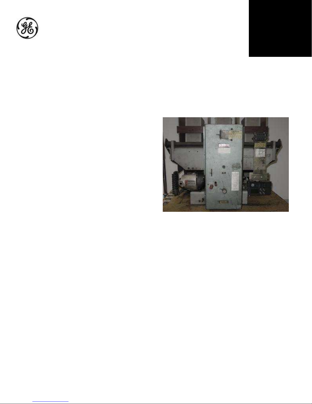
1. Open the breaker and remove it from its enclosure.
Carefully place the breaker on a suitable work surface so
that the rear of the breaker is initially accessible.
2. If the conversion kit is to be installed on a fused breaker
(LAF series), remove the fuse structure from the upper
(line) studs to allow easier access to the load studs.
Additional work may be required to install kit into fused
breaker.
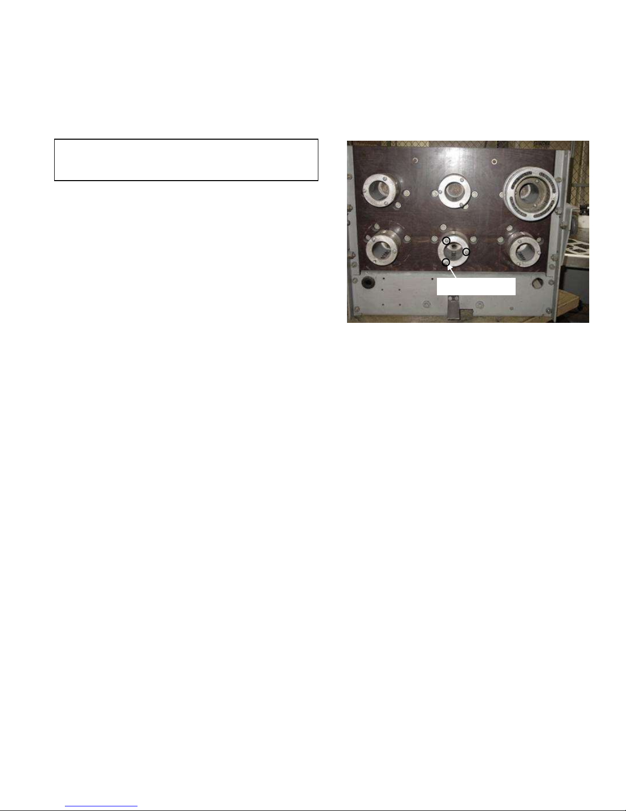
3. Loosen the three Allen-head screws securing each of the
primary disconnects to the line (upper) and load (lower)
studs and remove the primary disconnects.
4. Remove the wires from the original current sensors (CTs),
if present, and slide off the CTs.
5. Remove manual charging handle. Remove the two bolts
holding the escutcheon to the breaker frame and lift off the
escutcheon.
6. Remove old flux shifter and mounting bracket. Also
remove old trip unit and its mounting bracket along with its
wire harness.
Figure 1: Primary disconnects removed from bottom studs
Page 6

5
SECTION 4. INSTALLING THE
CONVERSION KIT
This section describes the installation of the Entelliguard,
MicroVersaTrip Plus and MicroVersaTrip PM and conversion
kit. The components provided with the kit are shown in Fig 2.
Mounting Plate
Figure 2: Components supplied with the conversion kit
Current Sensor
(LA4000-Blue)
Wiring Harness
Trip Unit
Connector
Hardware
Flux Shifter
Assembly
Programmer
Bracket Assembly
Page 7

6
Installing Flux Shifter Reset Bracket
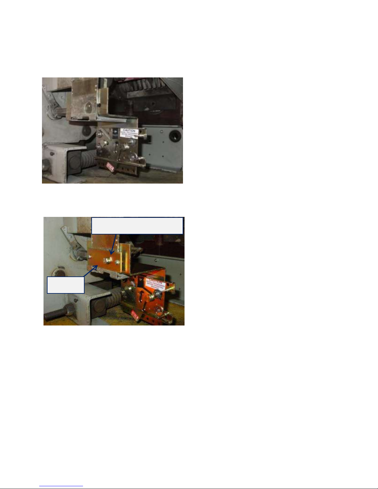
Replace existing reset bracket with new bracket as shown in
Figure 3 and Figure 4 below:
Install Flux Shifter Asm
The Flux shifter mounting location is shown in Figure 5 below:
Mount Flux Shifter assembly to breaker frame as shown in
figures 6 and 7.
Install the Reset Link between the reset Bracket and Flux
Shifter Assembly as shown in Figure 8.
Adjust Flux Shifter to breaker latch with breaker in the charged
position. Set the .031 dimension as shown in figure 8 and lock
with Jam nut.
Old Reset Asm
to be removed
New Reset Asm to
replace old Asm
Existing hardware
to be used to install
new reset Asm
Figure 3: Old and New Reset Assembly
Breaker
Cross bar
Existing
hardware
Figure 4: Installed Reset Assembly
These 2 existing holes are to be
used to mount Flux shifter Asm
to side of breaker mech
Figure 5: Flux Shifter mounting location
MTG hardware 1/4 x3/4 Long Hex Head
F/S MTG
spacers
positioned
as shown to
space F/S
assy away
from
breaker
mech side
frame
Reset Link
Jam Nut
Set .031
Figure 6: Flux Shifter mounting
Figure 7: Flux Shifter mounting
Figure 8: Installing Reset Link
Page 8

7
Installing the Trip Unit Wiring Harness
CAUTION: Pins in the connectors may come loose in
shipping. Check all wiring harness connectors to ensure that
the pins are tight. Reseat pins as necessary.
Use the following procedure to install the trip unit wiring
harness to the mounting plate.
1. The wiring harness includes a 36-pin connector, shown in
Figure 9, that must be assembled and installed onto the trip
unit mounting plate before the trip unit can be installed.
CAUTION: The adapter bracket must be installed onto the
trip unit 36-pin connector and trip unit mounting plate as
described below. Failure to do so will result in harness plug
failure and the trip unit will not provide protection. If the
converted breaker is energized or primary injected with the
mounting plate not installed or installed improperly, damage
will result to the trip unit, wire harness, 36-pin connector, and
current sensors. Failure to adhere to these instructions will
void all warranties.
2. Slide the adapter bracket onto the 36-pin connector, as
shown in Figure 10. Be sure that the beveled corners of the
trip unit connector are facing toward the right side, the
adapter bracket slides are in place behind the notches on
either side of the connector body, and the connector’s tabs
align with the notches on the bottom of the adapter bracket.
3. Hold the adapter bracket tight to the trip unit connector and
bend the two locking tabs on the adapter bracket over the
connector body, as shown in Figure 11.
Figure 9. 36-pin trip unit connector
Figure 10 36-pin connector adapter bracket
Page 9

8
Figure 11. Adapter bracket locking tabs
4.Slide the adapter bracket and connector assembly over the
guide pins of the trip unit bracket. Press the two steel push
nuts provided onto the guide pins using a nut driver, as
shown in Figure 12, until the assembly is held firmly
against the trip unit mounting plate.
5. While holding the adapter bracket and connector assembly
firmly in place against the mounting plate, bend the two
locking tabs on the mounting plate into the mating notches
on the adapter bracket using a screwdriver, as shown in
Figure 13.
Figure 12. Installing the push nuts onto the guide pins
Figure 13. Locking tabs on mounting plate
Page 10
9
Installing the Trip Unit Mounting Bracket
Install Trip Unit mounting bracket as shown in figure 14 and
secure in this position with locking plate shown in Figure 15.
Hardware ¼-20 Hex Hd ¾ Lg
Locking
Figure 14: Trip Unit bracket mounting
Figure 15: Securing Trip Unit bracket
Page 11

10
Installing the Current Sensors
Install current sensors as shown in Figure 16 and 17.
Use existing holes in the breaker back frame to mount C/T
support plate.
Next install the wire harness to the Current Sensors as
shown in Figure 18 below:
Connect the CT leads from the trip unit harness to each
of the CT’s. The leads are labeled with the letter of the
corresponding pole (A is the right pole from the rear of
the breaker, B is the center, C is the left), and are also cut
to the appropriate lengths. Attached the white wire to the
terminal marked white.
Reattach the primary disconnect assemblies to all the
studs. To aid in reinstalling disconnect 3-1/4-20 ¾ long
screws are supplied in hardware package. These screws
are used (only) to help force disconnects onto their
corresponding studs. Disconnects are to be secured in
position using the original breaker hardware.
Hardware ¼-20 Hex Hd ¾ Lg
Split Lk Washer
CT Support Plate
Figure 16: Position of current sensors
Figure 17: Installing Current sensors
Figure 18: Installing Wire Harness
Page 12

11
Installing the Communications Harness
The communications harness is used if the trip unit is to
communicate with a power management control system.
The communications connector, included in the trip unit
wiring harness, is mounted with the supplied angle
bracket. This bracket has two small holes on one arm for
attaching with screws to a convenient spot on the breaker
frame and a large rectangular hole in the other arm for
mounting the connector.
The communications connector should be installed on
the breaker on the same side as the breaker
compartment’s door hinge, to protect it from damage
when the compartment door is opened or closed. Attach
the supplied caution labels, shown in Figure 19, to both
the breaker and the compartment door as a warning to
disconnect the communications harness before removing
the breaker from the compartment.
Figure 19. Caution label to be applied to the breaker and
compartment door
Note: If communications is not required for this
application, install the two pin wire harness (supplied with
the kit) to provide 24V DC to the trip unit. Power supply of
24V DC is essential for advanced functions of the trip unit
such as backlight display, status LED indicator, event log
etc.
SECTION 5. INSTALLING THE TRIP
UNIT
Use the following procedure to install the trip unit.
1. Pull out the locking lever on the trip unit mounting plate
until it snaps into the open position, as shown in Figure 12.
2. Carefully line up the 36-pin connector mounting pins with
the two holes on the sides of the connector cutout on the
rear of the trip unit. The alignment pin on the rear of the
trip unit must fit through the hole in the locking lever.
3. Push the trip unit against the mounting plate until it locks
into position. The locking lever will automatically snap
back to secure the trip unit. Figure 26 shows an installed
trip unit.
CAUTION: Ensure that the trip unit connector is seated
firmly into the 36-pin connector on the mounting plate.
Improper mating of the connectors will cause damage to the
trip unit, wire harness, connector, and current sensors.
4. The breaker escutcheon may now be reattached. To
remove the trip unit, slide out the locking lever to release
the alignment pin, then carefully pull the trip unit straight
off the mounting plate.
Figure 20. Trip unit installed on the breaker
Page 13

12
SECTION 6. FOUR-WIRE GROUND
FAULT OPTION
The ground fault option for four-wire installations requires the
installation of an additional current sensor on the neutral bus in
the equipment. The sensor is connected to the trip unit through
the connector provided in the wiring harness.
1. Mount the neutral sensor on the outgoing neutral lead,
normally in the bus or cable compartment in the
equipment. Figure 27 shows the sensor outlines for the
3000 A through 4000 A frame sizes.
2. Connect the neutral sensor wire harness to the correct taps
on the sensor. To maintain the same polarity as the phase
sensors, connect the white wire to the common terminal,
black to the tap.
3. Route the wires through the equipment and connect to the
two-pin connector on the trip unit wiring harness, routed
through the rear of the breaker with the CT wires. The
wires should be tied to the breaker frame in an easily
accessible location.
Page 14

13
SECTION 7. TESTING AND TROUBLE-
SHOOTING
WARNING: Do not change taps on the current sensors or
adjust the trip unit settings while the breaker is carrying
current. Failure to adhere to these instructions will void all
warranties.
Testing
1. Verify that the trip unit is securely installed by performing
a continuity test on the CT wiring and the trip unit.
a. Disconnect the black CT wires at each phase sensor.
b. Check for continuity with a continuity tester or VOM
from the white lead of the phase A CT to the white lead
of the phase B CT.
c. Repeat this continuity test for the white leads of the
phase A and phase C CTs.
d. Measure the resistance across each phase sensor and
compare the values measured to the values listed in
Table 1.
e. Reconnect the black CT leads to all of the phase
sensors. Ensure that this is done before continuing with
performance testing of the breaker.
CAUTION: In addition to the continuity test described in Step
1 and before performance testing of the converted breaker,
each phase of the breaker should be primary injected with a
current level of about 10%, but no more than 20%, of the CT
rating. During the application of test current, activate the trip
unit screen by depressing the battery button on the trip unit
face and check that the test current is displayed on the screen
for each phase tested. If the trip unit fails to display the test
current, stop the test immediately and verify the installation of
the trip unit and wire harness before proceeding with any
additional testing.
WARNING: If the converted breaker is energized or tested by
primary injection with a sufficiently high test current with a
loose or open circuit between the CTs and the trip unit,
damage will occur to the trip unit, wire harness, 36-pin trip
unit connector, and CTs. Failure to adhere to these
instructions will void all warranties.
2. Check the insulation on the primary circuit with a 1,000-
volt Meggar.
3. Measure the resistance across the line and load terminals
for each phase using a micro-ohmmeter or millivolt tester.
If the resistance differs considerably from phase to phase,
Figure 21. Neutral sensor outline for 3000A through 4000A breakers
Page 15

14
the electrical connections may not be properly tightened or
it could also indicate improper contact wipe.
4. To verify that the breaker has been properly retrofitted,
perform a primary injection test on each phase. This test
will check the CTs, bus, wiring harness, flux shifter, and
trip unit as a complete system.
a. A high-current, low-voltage power supply should be
connected across each line and load terminal to simulate
an overcurrent fault.
b. Set the long-time trip at 0.5 to minimize the breaker
stress.
c. When ground fault is installed, the test can be
performed by wiring two adjacent poles in series or by
using the GE Digital Test Kit, cat. no. TVRMS2. This
will prevent the breaker from tripping because of an
unbalanced current flow. For Entelliguard TU use
GTUTK20.
CAUTION: Do not attempt to use GE Test Kit cat. no.
TVTS1 or TVRMS on Entelliguard trip unit and do not use
GTUTK20 on MVT trip unit.
Trouble-Shooting
When malfunctioning is suspected, first examine the breaker
and its power system for abnormal conditions such as the
following:
• The breaker is not tripping in response to overcurrent
conditions or incipient ground faults.
• The breaker is remaining in a trip-free state because of
mechanical interference along its trip shaft.
• The shunt trip (if present) is activating improperly.
Nuisance Tripping on Ground Fault-Equipped Breakers
When nuisance tripping occurs on breakers equipped with
ground fault trip, a probable cause is the existence of a false
ground signal. Each phase sensor is connected to summing
circuitry in the trip unit. Under no-fault conditions on threewire load circuits, the currents add to zero and no ground signal
is developed. This current sum is zero only if all three sensors
have the same electrical characteristics. If one sensor differs
from the others (such as by a different rating or wrong tap
setting), the circuitry can produce an output sufficient to trip the
breaker. Similarly, a discontinuity between any sensor and the
trip unit can cause a false trip signal.
The sensors and their connections should be closely examined
if nuisance tripping is encountered on any breaker whose
Entelliguard, MicroVersaTrip Plus or MicroVersaTrip PM trip
unit has previously demonstrated satisfactory performance.
After disconnecting the breaker from all power sources,
perform the following procedure:
1. Check that all phase sensors are the same type (current
range).
2. Verify that the tap settings on all three phase sensors are
identical.
3. Verify that the wiring harness connections to the sensors
have the proper polarity (white lead to common, black lead
to tap), as shown in the cabling diagrams1.
4. On ground fault breakers serving four-wire loads, check
that the neutral sensor is properly connected, as indicated
in Figure 27. In particular, check the following:
a. Verify that the neutral sensor has the same rating and
tap setting as the phase sensors.
b. Verify continuity between the neutral sensor and its
equipment-mounted secondary disconnect block. Also
check for continuity from the breaker-mounted neutral
secondary disconnect block through to the trip unit
wiring harness connector.
c. If the breaker’s lower studs connect to the power
source, then the neutral sensor must have its load end
connected to the source.
d. Verify that the neutral conductor is carrying only the
neutral current associated with the breaker’s load
current (the neutral is not shared with other loads).
5. If the preceding steps fail to identify the problem, then
measure the sensor resistances. The appropriate values are
listed in Table 1. Since the phase and neutral sensors are
electrically identical, their resistances should agree closely.
Breaker
CT Rating, A
Resistance, ohms
LA-4000-Blue
4000
29–39
Table 1. CT resistance values.
Page 16

15
GE Industrial Systems
General Electric Company
41 Woodford Ave., Plainville, CT 06062
DEH40015 R01 © 2010 General Electric Company
These instructions do not cover all details or variations in equipment nor do they provide for every possible contingency that may be
met in connection with installation, operation, or maintenance. Should further information be desired or should particular problems
arise that are not covered sufficiently for the purchaser’s purposes, the matter should be referred to the GE Company.
 Loading...