

GE PFS23KSHSS, GNS23GGHBB, GNS23GGHWW, GNS23GMHES, PNS20KSHSS Use & Care Guide
GEAppliances.com
Safety Instructions ............2, 3
Operating Instructions
Additional Features. . . . . . . . . . . . . . . . . .9
Automatic Icemaker ............12-13
Care and Cleaning .............13–14
Controls ..........................4–5
Crispers and Pans ..................10
Freezer ............................11
Replacing the Light Bulbs ...........15
Shelves and Bins ..................8, 9
Water Filter .......................6, 7
Installation Instructions
Installing the Refrigerator .......17–21
Installing the Water Line ........30–32
Preparing to Install
the Refrigerator ....................16
Removing and Replacing
the Doors (Double Door
Refrigerator Models only) .......27–29
Removing and Replacing the
Freezer Drawer ................22, 23
Reversing the Door Swing
(Single Door Refrigerator
Models only) ...................24–26
Troubleshooting Tips ......33–37
Profile Bottom Freezer
Normal Operating Sounds ..........33
Consumer Support
Consumer Support ........Back Cover
Performance Data Sheet .......39-40
Warranty ..........................38
Owner’s Manual and
Installation Instructions
Models 20, 21, 22 and 23
Congélateur inférieur
Réfrigérateurs
Manuel d’utilisation
et d’installation
La section française commence à la page 40
Congelador inferior
Refrigeradores
Manual del
propietario e
instalación
La sección en español empieza en la página 83
Write the model and serial
numbers here:
Model # ____________________
Serial # _____________________
Find these numbers on a label
on the right side, near the top of the
refrigerator compartment.
Refrigerators
200D9366P016 49-60603-6 10-14 GE
IMPORTANT SAFETY INFORMATION.
READ ALL INSTRUCTIONS BEFORE USING.
SAFETY
GE Appliances website
For more information on your refrigerator’s operation, visit www.GEAppliances.com or
call 800.GECARES (800.432.2737). In Canada visit GEAppliances.ca or call 800.561.3344.
REFRIGERATOR SAFETY INFORMATION
This is the safety alert symbol. This symbol alerts you to potential hazards that can kill or hurt you and others. All safety
messages will follow the safety alert symbol and the word “DANGER”, “WARNING”, or “CAUTION”. These words are defined
as:
DANGER
WARNING
CAUTION
Indicates a hazardous situation which, if not avoided, will result in death or serious injury.
Indicates a hazardous situation which, if not avoided, could result in death or serious injury.
Indicates a hazardous situation which, if not avoided, could result in minor or moderate injury.
IMPORTANT SAFETY INSTRUCTIONS
WARNING
To reduce the risk of fire, explosion, electric shock, or injury when using your
refrigerator follow these basic safety precautions:
This refrigerator must be properly installed and located in
accordance with the Installation Instructions before it is used.
Unplug the refrigerator before making repairs, replacing a light
bulb, or cleaning.
Note: Power to the refrigerator cannot be disconnected by any
setting on the control panel.
Note: Repairs must be performed by a qualified service
professional.
Replace all parts and panels before operating.
Do not store or use gasoline or other flammable vapors and
liquids in the vicinity of this or any other appliance.
Because of potential safety hazards under certain conditions,
we strongly recommend against the use of an extension cord.
However, if you must use an extension cord, it is absolutely
necessary that it be a UL-listed (in the United States) or a CSA
certified (in Canada), 3-wire grounding type appliance extension
cord having a grounding type plug and outlet and that the electrical
rating of the cord be 15 amperes (minimum) and 120 volts.
To prevent suffocation and entrapment hazards to children,
remove the fresh food and freezer doors from any refrigerator
before disposing of it or discontinuing its use.
Do not allow children to climb, stand or hang on the door
handles or the shelves in the refrigerator. They could seriously
injure themselves.
IMPORTANT SAFETY INSTRUCTIONS
CAUTION
Do not clean glass shelves or covers with warm water
when they are cold. Glass shelves and covers may break if
exposed to sudden temperature changes or impact, such
as bumping or dropping. Tempered glass is designed to
shatter into many small pieces if it breaks.
Keep fingers out of the “pinch point” areas; clearances
between the doors and between the doors and cabinet are
necessarily small. Be careful closing doors when children
are in the area.
To reduce the risk of injury when using your refrigerator, follow these basic
safety precautions.
2
Do not touch the cold surfaces in the freezer compartment
when hands are damp or wet, skin may stick to these
extremely cold surfaces.
Do not refreeze frozen foods which have thawed
completely.
In refrigerators with automatic icemakers, avoid contact
with the moving parts of the ejector mechanism, or with the
heating element that releases the cubes. Do not place fingers
or hands on the automatic ice making mechanism while the
refrigerator is plugged in.
GEAppliances.com
SAFETY (CONT.)
INSTALLATION
WARNING
Explosion Hazard.
Keep flammable materials and vapors, such as gasoline, away from refrigerator. Failure to do so can
result in fire, explosion, or death.
CONNECTING ELECTRICITY
WARNING
Plug into a grounded 3-prong outlet
Do not remove the ground prong
Do not use an adapter
Do not, under any circumstances, cut or remove the third (ground) prong from the power cord.
For personal safety, this appliance must be properly grounded.
The power cord of this appliance is equipped with a 3-prong
(grounding) plug which mates with a standard 3-prong
(grounding) wall outlet to minimize the possibility of electric
shock hazard from this appliance.
Have the wall outlet and circuit checked by a qualified
electrician to make sure the outlet is properly grounded.
Where a standard 2-prong wall outlet is encountered, it
is your personal responsibility and obligation to have it
replaced with a properly grounded 3-prong wall outlet. Do
not use an adapter.
The refrigerator should always be plugged into its own
individual electrical outlet which has a voltage rating that
matches the rating plate.
Electrical Shock Hazard.
Failure to follow these instructions can result in
death, fire, or electrical shock.
A 115 Volt AC, 60 Hz, 15- or 20-amp fused, grounded
electrical supply is required. This provides the best
performance and also prevents overloading house wiring
circuits which could cause a fire hazard from overheated
wires.
Never unplug your refrigerator by pulling on the power cord.
Always grip plug firmly and pull straight out from the outlet.
Repair or replace immediately all power cords that have
become frayed or otherwise damaged. Do not use a cord
that shows cracks or abrasion damage along its length or
at either end.
When moving the refrigerator away from the wall, be
careful not to roll over or damage the power cord.
USE OF ADAPTER PLUGS
Adapter plugs are not permitted in Canada.
PROPER DISPOSAL OF YOUR OLD REFRIGERATOR
WARNING
Remove fresh-food and freezer doors from the refrigerator, prior to disposal. Failure to do so can
result in child entrapment which can lead to death or brain damage.
IMPORTANT:
Suffocation and child entrapment hazard.
Child entrapment and suffocation are not problems
of the past. Junked or abandoned refrigerators are
still dangerous even if they will sit for “just a few
days.” If you are getting rid of your old refrigerator,
please follow the instructions below to help prevent
accidents.
Before You Throw Away Your Old Refrigerator or
Freezer:
Take off the fresh food and freezer doors.
Leave the shelves in place so that children may
not easily climb inside.
Refrigerants
All refrigeration products contain refrigerants,
which under federal law must be removed prior
to product disposal. If you are getting rid of an old
refrigeration product, check with the company
handling the disposal about what to do.
READ AND FOLLOW THIS SAFETY INFORMATION CAREFULLY.
SAVE THESE INSTRUCTIONS
3
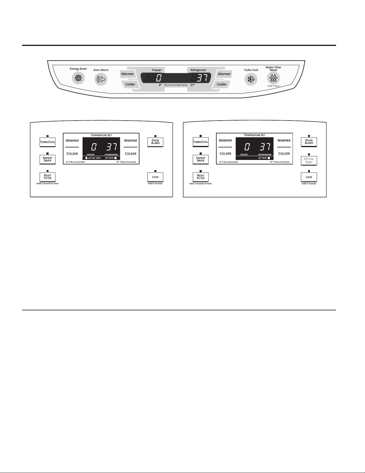
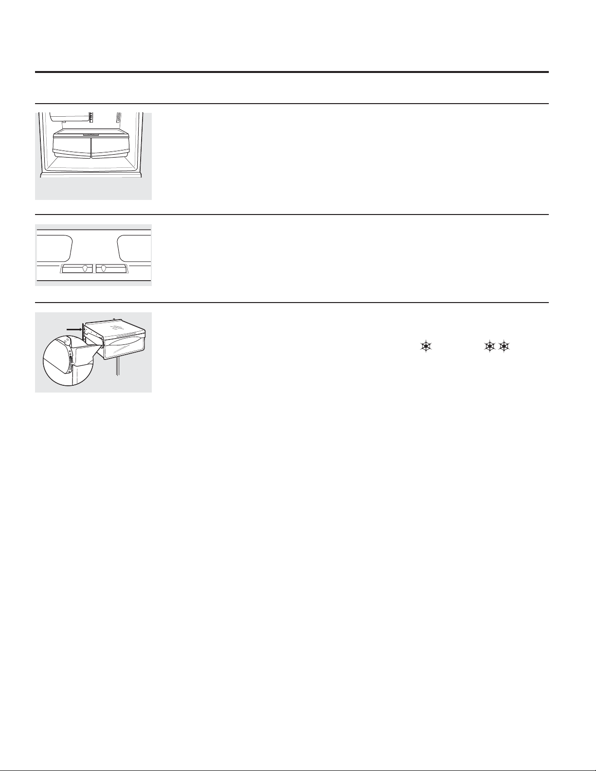
About the controls with temperature settings.
(on some models)
ACTUAL
TEMP
(FIG A)
(on some models)
(FIG B)
NOTE: The refrigerator is shipped with protective film covering the temperature controls. If this film was not removed
during installation, remove it now.
The temperature controls are preset in the factory at 37°F for the refrigerator compartment and 0°F for
the freezer compartment. Allow 24 hours for the temperature to stabilize to the preset recommended
settings.
The temperature controls can display both the SET temperature as well as the actual temperature in the
refrigerator and freezer. The actual temperature may vary slightly from the SET temperature based on
usage and operating environment.
Setting either or both controls to OFF stops cooling in both the freezer and refrigerator compartments,
but does not shut off electrical power to the refrigerator.
Changing the Temperature
For Controls-on-the-Door Models:
FIG. “A” To change the temperature, press and release the
WARMER or COLDER pad. The ACTUAL TEMP light will come on
and the display will show the actual temperature. To change the
temperature, tap either the WARMER or COLDER pad until the
desired temperature is displayed.
FIG. “B” To visualize the real temperature press and release
the ACTUAL TEMP pad. The display will show the actual
temperature for 10 seconds.
To change the temperature, tap either the WARMER or
COLDER pad until the desired temperature is displayed. The SET
TEMP light will come on during this process.
For Controls Inside the Refrigerator:
Opening the door displays the actual temperature. To change
the temperature, press either the WARMER or COLDER touch
pads until the desired temperature is displayed.
Once the desired temperature has been set, the temperature
display will return to the actual refrigerator and freezer
temperatures after 5 seconds. Several adjustments may be
required.
Each time you adjust controls, allow 24 hours for the refrigerator
to reach the temperature you have set.
To turn the cooling system off, tap the WARMER pad for either
the refrigerator or the freezer until the display shows OFF. To
turn the unit back on, press the COLDER pad for either the
refrigerator or freezer. Then press the COLDER pad again and it
will go to the preset points of 0°F for the freezer and 37°F for the
refrigerator. Setting either or both controls to OFF stops cooling
in both the freezer and refrigerator compartments, but does not
shut off electrical power to the refrigerator.
4
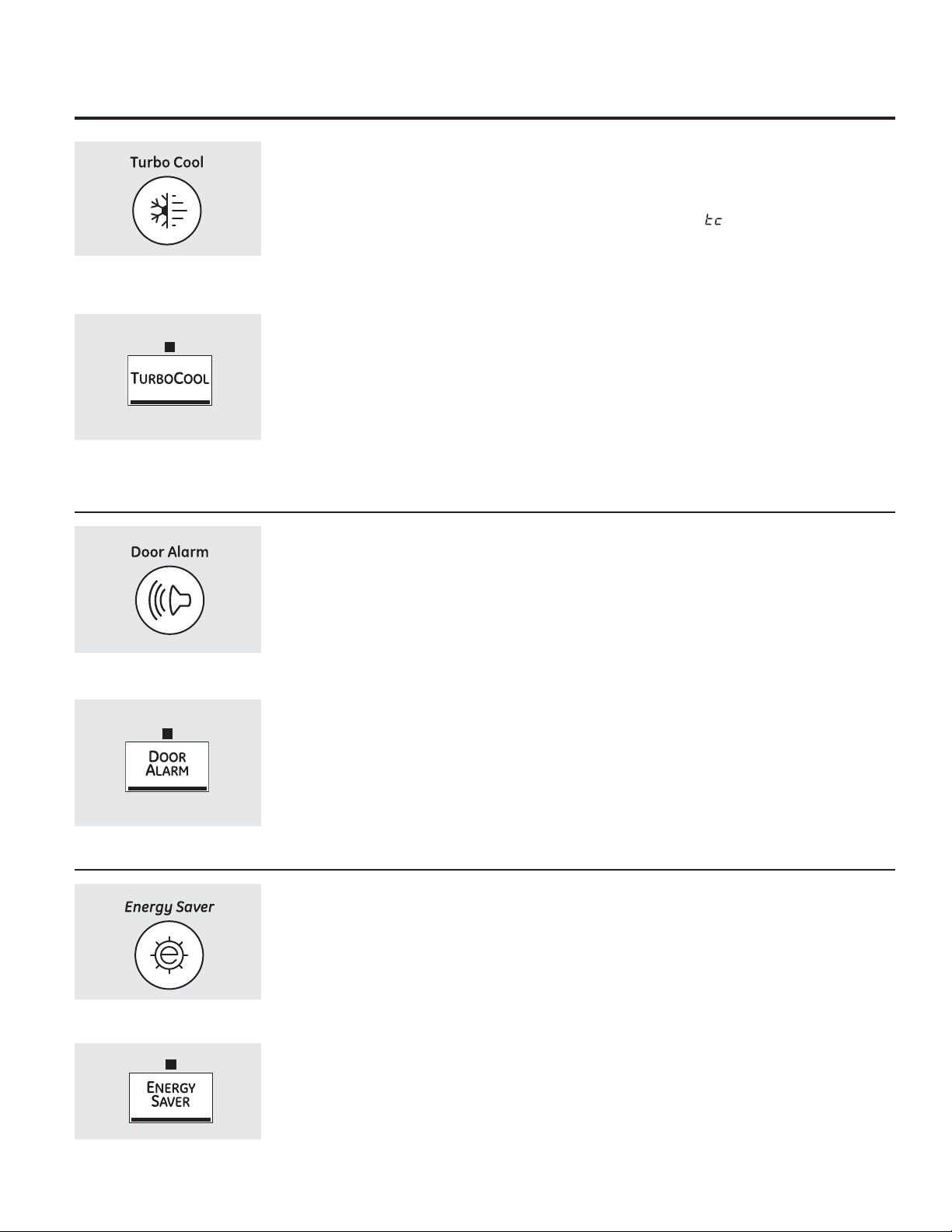
About TurboCool.
(on some models)
(on some models)
™
(on some models) GEAppliances.com
How it Works
TurboCool rapidly cools the refrigerator
compartment in order to more quickly
cool foods. Use TurboCool when adding
a large amount of food to the refrigerator
compartment, putting away foods after they
have been sitting out at room temperature or
when putting away warm leftovers. It can also
be used if the refrigerator has been without
power for an extended period.
Once activated, the compressor will turn
on immediately and the fans will cycle on
and off at high speed as needed for eight
hours. The compressor will continue to run
until the refrigerator compartment cools to
approximately 34°F (1°C), then it will cycle on
and off to maintain this setting. After 8 hours, or
if TurboCool is pressed again, the refrigerator
compartment will return to the original setting.
How to Use
Press TurboCool. The refrigerator temperature
display will show .
After TurboCool is complete, the refrigerator
compartment will return to the original setting.
NOTES: The refrigerator temperature cannot
be changed during TurboCool.
The freezer temperature is not
affected during TurboCool.
When opening the refrigerator door
during TurboCool, the fans will
continue to run if they have cycled on.
About Door Alarm (on some models)
(on some models)
(on some models)
(on some models)
The door alarm will sound if any door is open
for more than 2 minutes. The beeping stops
when you close the door.
About Energy Saver (on some models)
This product is equipped with an Energy Saver
feature. The refrigerator is shipped with the
Energy Saver feature enabled.
Over time, moisture can form on the front
surface of the refrigerator cabinet and cause
rust. If moisture does appear on the front
surface of the refrigerator cabinet, turn off the
Energy Saver feature by pressing and releasing
the ENERGY SAVER pad on the control panel.
(on some models)
5
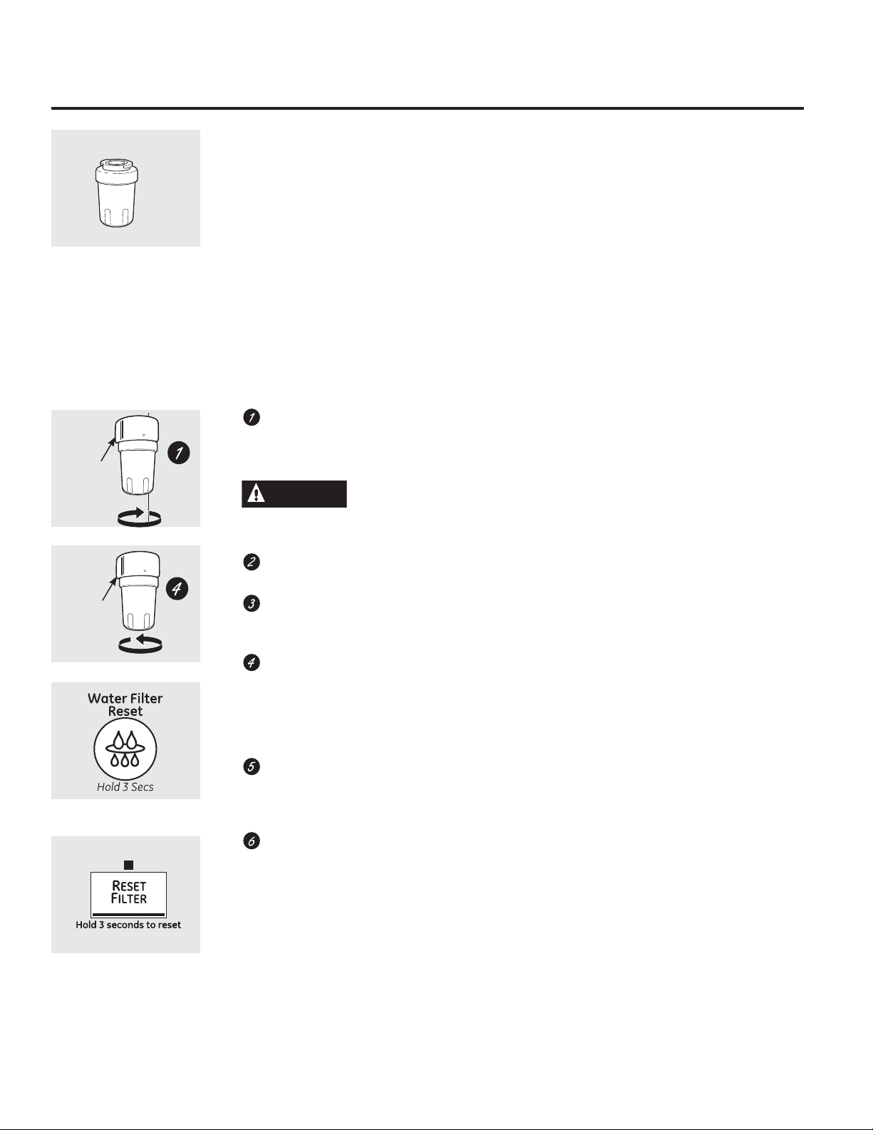
About the water filter. (on 22 and 23 models only)
Cartridge
Holder
Cartridge
Holder
(on some models)
Water Filter Cartridge
The water filter cartridge is located in the
back upper right corner of the refrigerator
compartment.
When to Replace the Filter
There is a replacement indicator light for
the water filter cartridge on the temperature
display. This light will turn orange to tell you
that you need to replace the filter soon. The
filter cartridge should be replaced when the
replacement indicator light turns red or if
the flow of water to the dispenser or icemaker
decreases.
Installing the Filter Cartridge
If you are replacing the cartridge, first
remove the old one by slowly turning it to
the left. DO NOT pull down on the cartridge.
A small amount of water may drip down.
CAUTION
system, the filter cartridge may be ejected as it is
removed. Use caution when removing.
Remove the protective foil from the end of
the cartridge.
Fill the replacement cartridge with water
from the tap to allow for better flow from
the dispenser immediately after installation.
Lining up the arrow on the cartridge
and the cartridge holder, slowly rotate the
cartridge clockwise until it stops. When the
cartridge is properly installed, you will feel it
“click” as it locks into place.
Do not overtighten.
Run water from the dispenser for
3 minutes (about 11ø2 gallons) to clear
the system and prevent sputtering.
See To Use the Dispenser section.
Press and hold the RESET WATER FILTER
pad for 3 seconds.
If air has been trapped in the
Filter Bypass Plug
You must use the filter bypass plug when a
replacement filter cartridge is not available. The
icemaker will not operate without the filter or
filter bypass plug.
Replacement Filters:
To order additional filter cartridges
in the United States, visit our Website,
GEAppliances.com, or call GE Parts and
Accessories, 800.626.2002.
Filter Model MWF
Customers in Canada should consult
the yellow pages for the nearest Mabe Service
Center.
(on some models)
6
NOTE: A newly-installed water filter
cartridge may cause water to spurt from
the dispenser.
About the water filter. (on 20 models only) GEAppliances.com
Water Filter Cartridge
The water filter cartridge is located in the
back upper right corner of the refrigerator
compartment.
When to Replace the Filter
The filter cartridge should be replaced when
the flow of water to the icemaker decreases, or
every 6 months.
Installing the Filter Cartridge
If you are replacing the cartridge, first
remove the old one. Open the cartridge
cover by pressing in on the tab at the front
and pulling down.
Remove the cartridge by slowly rotating it
counterclockwise. A small amount of water
may drip down.
CAUTION
system, the filter cartridge may be ejected as it is
removed. Use caution when removing.
Remove the protective foil from the end of
the cartridge.
Lining up the arrow on the cartridge and
the cartridge holder, slowly rotate the
cartridge clockwise until it stops. When the
cartridge is properly installed, you will feel it
“click” as it locks into place. The grip on the
end of the cartridge should be positioned
vertically.
Do not overtighten.
Close the cartridge cover.
If air has been trapped in the
Filter Bypass Plug
You must use the filter bypass plug when a
replacement filter cartridge is not available. The
icemaker will not operate without the filter or
filter bypass plug.
Replacement Filters:
To order additional filter cartridges in
the United States, visit our Website,
GEAppliances.com, or call GE Parts and
Accessories, 800.626.2002.
Filter Model GSWF
Customers in Canada should consult the yellow
pages for the nearest Mabe Service Center.
7

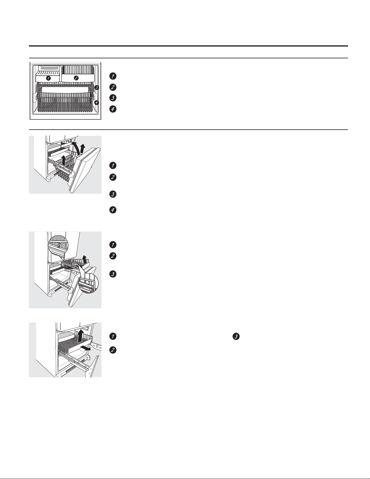
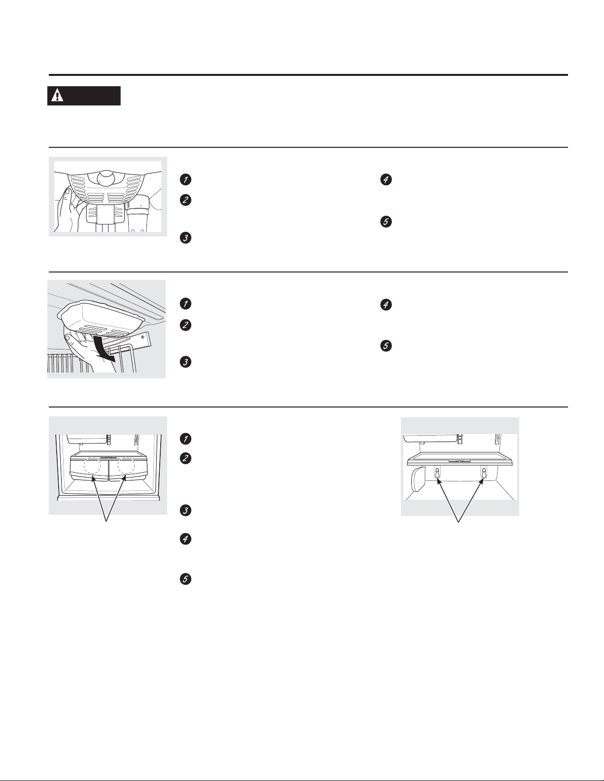
About the shelves and bins.
Not all features are on all models.
Rearranging the Shelves
Shelves in the refrigerator compartment are adjustable.
Refrigerator Compartment
To remove:
Remove all items from the shelf.
Tilt the shelf up at the front.
Lift the shelf up at the back and bring the
Some models have wire shelves
that can be adjusted in the same
manner.
shelf out.
To replace:
While tilting the shelf up, insert the top hook
at the back of the shelf in a slot on the
track.
Lower the front of the shelf until the bottom
of the shelf locks into place.
Spillproof Shelves (on some models)
Spillproof shelves have special edges to help
prevent spills from dripping to lower shelves. To
remove or replace the shelves, see Rearranging
the Shelves.
Slide-Out Spillproof Shelf (on some models)
The slide-out spillproof shelf allows you to
reach items stored behind others. The special
edges are designed to help prevent spills from
dripping to lower shelves.
To remove:
Remove all items from shelf.
Remove the shelf from the compartment by
lifting up and out.
Remove the glass shelf from the frame by
sliding the shelf out until it stops.
Tuck-Away Shelf (on some models)
This shelf can retract to half its size for storage
of tall items on the shelf below.
To remove:
Pull the shelf out and up.
Slide the shelf back until it stops.
Pull the shelf up to release it from the front
of the frame.
Slide the shelf back to release it from the
back of the frame.
To reinstall the glass shelf, reverse these
instructions.
Make sure that the shelf sits flat after
reinstallation and doesn’t move freely from side
to side.
Make sure you push the shelves all the way in
before you close the door.
To return the shelf to its original position,
pull up and forward on the shelf. Push
down slightly to lock the shelf into position.
8
GEAppliances.com
Adjustable Bins on the Door
Adjustable bins can easily be carried from
refrigerator to work area.
To remove: Lift bin straight up, then pull out.
To replace or relocate: Slide in the bin just
above the molded door supports, and push
down. The bin will lock in place.
Non-Adjustable Bins on the Door
To remove: Lift the bin straight up, then pull out.
To replace: Engage the bin in the molded
supports on the door and push down. It will lock
in place.
About the additional features.
The snugger helps prevent tipping, spilling or
sliding of small items stored on the door shelf.
Grip the finger hold near the rear of the snugger
and move it to fit your needs.
Shelf Saver Rack (on some models)
Slide-out beverage rack holds twelve cans of
soda or two wine/water bottles (lengthwise).
It can be removed for cleaning.
To remove, slide the rack out to the stop
position, lift the rack up and past the stop
position and lift it out.
9
About the crispers and pans.
Not all features are on all models.
Fruit and Vegetable Crisper
Excess water that may accumulate in the
bottom of the drawers or under the drawers
should be wiped dry.
Adjustable Humidity Crisper (on some models)
Second slot
from top
Slide the control all the way to the HIGH setting
to provide high humidity recommended for
most vegetables.
Slide the control all the way to the LOW setting
to provide lower humidity levels recommended
for most fruits.
Adjustable Temperature Deli Pan (on some models)
When the pan is placed in the 2nd slot from
the top of the track and the lever is set at
COLDEST, air from the freezer is forced around
the pan to keep it very cold.
You can move the pan to any location if you
don’t want the extra cold storage.
The settings can be adjusted anywhere
between cold and coldest .
When set at cold, the pan will stay at the
normal refrigerator temperature.
The coldest setting provides the coldest storage
area.
10
About the freezer. GEAppliances.com
Not all features are on all models.
Freezer Shelves and Baskets
Appearance and features may vary
Appearance may vary
A shelf above the ice storage bin
A half-width basket
A shallow full-width basket
A deep full-width basket
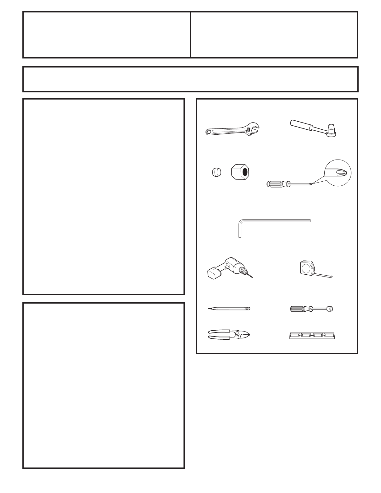
Basket Removal
To remove the deep full-width basket on
freezer drawer models:
Open the freezer drawer until it stops.
The freezer basket rests on the inside tabs
on the drawer slides.
Lift the basket so that it is out of all 6 slide
bracket tabs.
Tilt the basket and lift out of the drawer.
To remove the half-width basket:
Pull the basket out to the stop location.
Lift the basket up at the front to release it
from the slides.
Lift the back up and out of the slide.
NOTE: Do not fill baskets higher than the rim of
the basket. This may cause baskets to stick or
jam when opening or closing.
When replacing the deep full-width basket:
Tilt the basket back and lower it down into
the drawer. Rotate the basket to a horizontal
position and press it down into the 6 alignment
tabs.
NOTE: Always be sure that the basket is seated
in all 6 slide bracket tabs before sliding back
into the freezer. The basket can be turned in
either direction front to back and installed into
the freezer.
When replacing the basket, make sure that
the wire tabs and wire hooks on the sides of the
basket go into the slots in the top of the upper
basket slides.
NOTE: Always be sure to fully close this basket.
Appearance may vary
Appearance may vary
To remove the shallow full-width basket:
Pull the basket out to the stop location.
Lift the front up and over the stop location.
Lift the basket up and out.
11
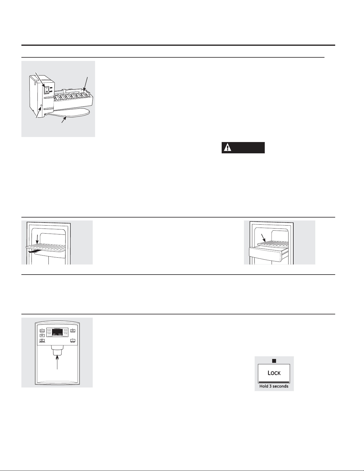
About the automatic icemaker.
A newly installed refrigerator may take 12 to 24 hours to begin making ice.
Power
Switch
Green
Power
Light
Shelf
To reach the power switch.
Feeler Arm
Ice Bin
Icemaker
Automatic Icemaker
(on some models)
7KHLFHPDNHUZLOOSURGXFHVHYHQFXEHVSHUF\FOH³
approximately 100–130 cubes in a 24-hour period,
depending on freezer compartment temperature,
room temperature, number of door openings and
other use conditions.
See below for how to access ice and reach the
power switch.
If the refrigerator is operated before the water
connection is made to the icemaker, set the power
switch in the O (off) position.
When the refrigerator has been connected to the
water supply, set the power switch to the l (on)
position. The icemaker power light will turn green
when the freezer light switch is pressed in or when
the freezer door is closed.
The icemaker will fill with water when it cools to 15°F
(–10°C). A newly installed refrigerator may take 12 to
24 hours to begin making ice cubes.
You will hear a buzzing sound each time the
icemaker fills with water.
Throw away the first few batches of ice to allow the
water line to clear.
Accessing Ice and Reaching the
Power Switch
To reach the icemaker power switch, pull the shelf
above the ice bin straight out. Always be sure to
replace the shelf.
To access ice, simply pull the bin forward.
Be sure nothing interferes with the sweep of the
feeler arm.
When the bin fills to the level of the feeler arm, the
icemaker will stop producing ice. It is normal for
several cubes to be joined together.
If ice is not used frequently, old ice cubes will
become cloudy, taste stale and shrink.
NOTE: In homes with lower-than-average water
pressure, you may hear the icemaker cycle multiple
times when making one batch of ice.
NOTE: Set the power switch to the O (off) position
if the water supply is shut off.
CAUTION
Avoid contact with the
moving parts of the ejector mechanism, or
with the heating element (located on the
bottom of the ice maker) that releases the
cubes. Do not place fingers or hands on the
automatic ice making mechanism while the
refrigerator is plugged in.
Shelf
Ice Bin
To access ice.
12
Spill Shelf
Dispenser Cradle
Icemaker Accessory Kit
If your refrigerator did not come already equipped
with an automatic icemaker, an icemaker accessory
kit is available at extra cost.
To Use the Dispenser (on some models)
Press the glass gently against the top of the
dispenser cradle.
The spill shelf is not self-draining. To reduce water
spotting, the shelf should be cleaned regularly.
If no water is dispensed when the refrigerator is first
installed, there may be air in the water line system.
Press the dispenser arm for at least two minutes to
remove trapped air from the water line and to fill the
water system. To flush out impurities in the water line,
throw away the first six glassfuls of water.
Check the back of the refrigerator for the specific
icemaker kit needed for your model.
Locking the Dispenser
Press the LOCK pad for 3 seconds to lock
the dispenser and control panel. To unlock,
press and hold the pad again for 3 seconds.
GEAppliances.com
To Use the Internal Water Dispenser
The water dispenser is located on the left wall inside
the refrigerator compartment.
To dispense water:
Hold the glass against the recess.
Push the water dispenser button.
Hold the glass underneath the dispenser for 2–3
seconds after releasing the dispenser button.
Water may continue to dispense after the button
is released.
Care and cleaning of the refrigerator.
Cleaning the Outside
The door handles and trim. Clean with a cloth
dampened with soapy water. Dry with a soft
cloth. Do not use wax on the door handles and
trim.
Keep the outside clean. Wipe with a clean
cloth lightly dampened with kitchen appliance
wax or mild liquid dish detergent. Dry and
polish with a clean, soft cloth.
Do not wipe the refrigerator with a soiled
dish cloth or wet towel. These may leave a
residue that can erode the paint. Do not use
scouring pads, powdered cleaners, bleach
or cleaners containing bleach because these
products can scratch and weaken the paint
finish.
(on some models)
If no water is dispensed when the refrigerator is first
installed, there may be air in the water line system.
Press the dispenser button for at least 2 minutes to
remove trapped air from the water line and to fill the
water system. During this process, the dispenser noise
may be loud as the air is purged from the water line
system. To flush out impurities in the water line, throw
away the first 6 glassfuls of water.
NOTE: To avoid water deposits, the dispenser should
be cleaned periodically by wiping with a clean cloth
or sponge.
The stainless steel panels and door handles.
The stainless steel doors and door handles
(on some models) can be cleaned with a
commercially available stainless steel cleaner.
Cleaners with oxalic acid such as Bar Keepers
Friend Soft Cleanser™ will remove rust,
tarnish and small blemishes. Use only a liquid
cleanser free of grit and rub in the direction
of the brush lines with a damp soft sponge.
Do not use appliance wax or polish on the
stainless steel.
Silver-plated plastic parts. Wash parts with
soap or other mild detergents. Wipe clean with
a sponge, damp cloth or paper towel.
Do not scrub with steel-wool pads or other
abrasive cleaners.
Cleaning the Inside
To help prevent odors, leave an open box
of baking soda in the refrigerator and freezer
compartments.
Unplug the refrigerator before cleaning.
If this is not practical, wring excess moisture
out of sponge or cloth when cleaning around
switches, lights or controls.
Use an appliance wax polish on the inside
surface between the doors.
8VHZDUPZDWHUDQGEDNLQJVRGDVROXWLRQ³
about a tablespoon (15 ml) of baking soda to
a quart (1 liter) of water. This both cleans and
neutralizes odors. Rinse and wipe dry.
After cleaning the door gaskets, apply a thin
layer of petroleum jelly to the door gaskets at
the hinge side. This helps keep the gaskets from
sticking and bending out of shape.
CAUTION
or covers with warm water when they are
cold. Glass shelves and covers may break
if exposed to sudden temperature changes
or impact such as bumping or dropping.
Tempered glass is designed to shatter into
many small pieces if it breaks.
Do not wash any plastic refrigerator parts in
the dishwasher.
Silver-accented plastic parts. Wash parts with
soapy water. Wipe clean with a sponge, damp
cloth or paper towel.
Do not scrub with steel-wool pads or other
abrasive cleaners.
Do not clean glass shelves
13

Care and cleaning of the refrigerator. (cont.)
Behind the Refrigerator
Be careful when moving the refrigerator away
from the wall. All types of floor coverings can
be damaged, particularly cushioned coverings
and those with embossed surfaces.
Raise the leveling legs located at the bottom
front of the refrigerator.
Pull the refrigerator straight out and return it
to position by pushing it straight in. Moving the
refrigerator in a side direction may result in
damage to the floor covering or refrigerator.
Preparing for Vacation
For long vacations or absences, remove food
and unplug the refrigerator. Clean the interior
with a baking soda solution of one tablespoon
(15 ml) of baking soda to one quart (1 liter) of
water. Leave the doors open.
Set the icemaker power switch to the O (off)
position and shut off the water supply to the
refrigerator.
Lower the leveling legs until they touch the
floor.
When pushing the refrigerator back, make
sure you don’t roll over the power cord or
icemaker supply line (on some models).
If the temperature can drop below freezing,
have a qualified servicer drain the water supply
system (on some models) to prevent serious
property damage due to flooding.
Preparing to Move
Secure all loose items such as base grille,
shelves and drawers by taping them securely
in place to prevent damage.
When using a hand truck to move the
refrigerator, do not rest the front or back of the
refrigerator against the hand truck. This could
damage the refrigerator. Handle only from the
sides of the refrigerator.
Be sure the refrigerator stays in an upright
position during moving.
14
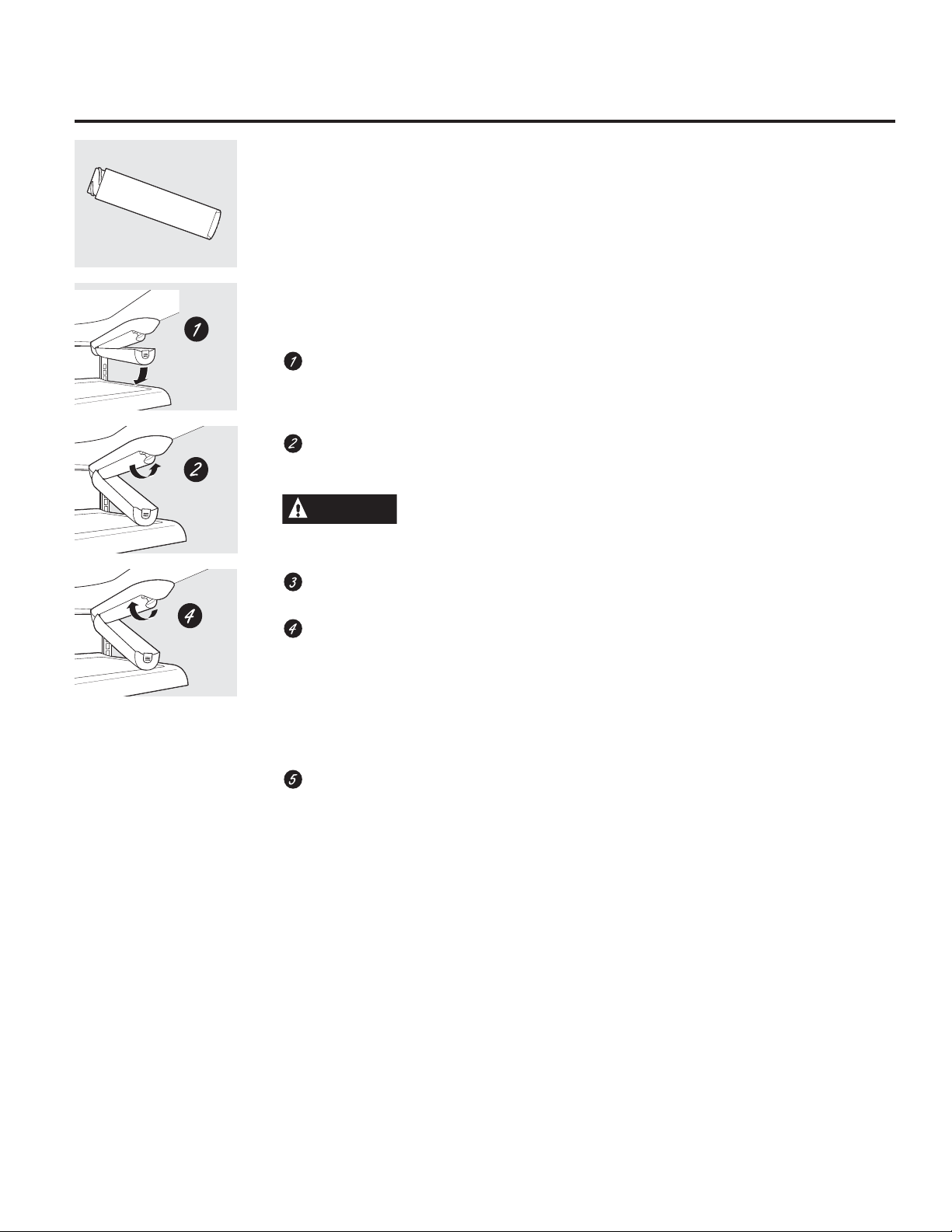
Replacing the light bulbs. GEAppliances.com
WARNING
live wire filament. (A burned-out light bulb may break when being replaced.)
Turning the control to the OFF position does not remove power to the light circuit.
Before replacing a burned-out light bulb, the refrigerator should be unplugged in order to avoid contact with a
Refrigerator Lights
Unplug the refrigerator.
To remove the light shield, grasp the shield
at the back and pull out to release the tabs
at the back.
Rotate the shield down and then forward to
release the tabs at the front of the shield.
NOTE: Appliance bulbs may be ordered from
GE Parts and Accessories, 800.626.2002.
Freezer Light
Unplug the refrigerator.
Remove the freezer basket for access. The
bulb is located at the rear of the freezer
inside a light shield.
To remove, grasp the shield at the top and
pull out to release the tabs at the bottom.
Appearance may vary
After replacing with an appliance bulb of
the same or lower wattage, replace the
shield.
Plug the refrigerator back in.
After replacing with an appliance bulb of
the same or lower wattage, replace the
shield and freezer basket.
Plug the refrigerator back in.
Lights are
behind crisper
drawers
Middle Lights
Unplug the refrigerator.
The bulbs are located behind the crisper
drawers. To remove the drawers, lift up
slightly while pulling the drawer past the
stop location.
Replace the bulbs with appliance bulbs
of the same or lower wattage.
Replace crisper drawers by sliding them
gently back onto the tracks while lifting up
slightly.
Plug the refrigerator back in.
Light Bulbs
15
Installation
Refrigerator
Instructions
Questions? Call 800.GE.CARES (800.432.2737) or visit our Website at: GEAppliances.com
In Canada, call 1.800.561.3344 or visit our Website at: www.GEAppliances.ca
Models 20, 21, 22 and 23
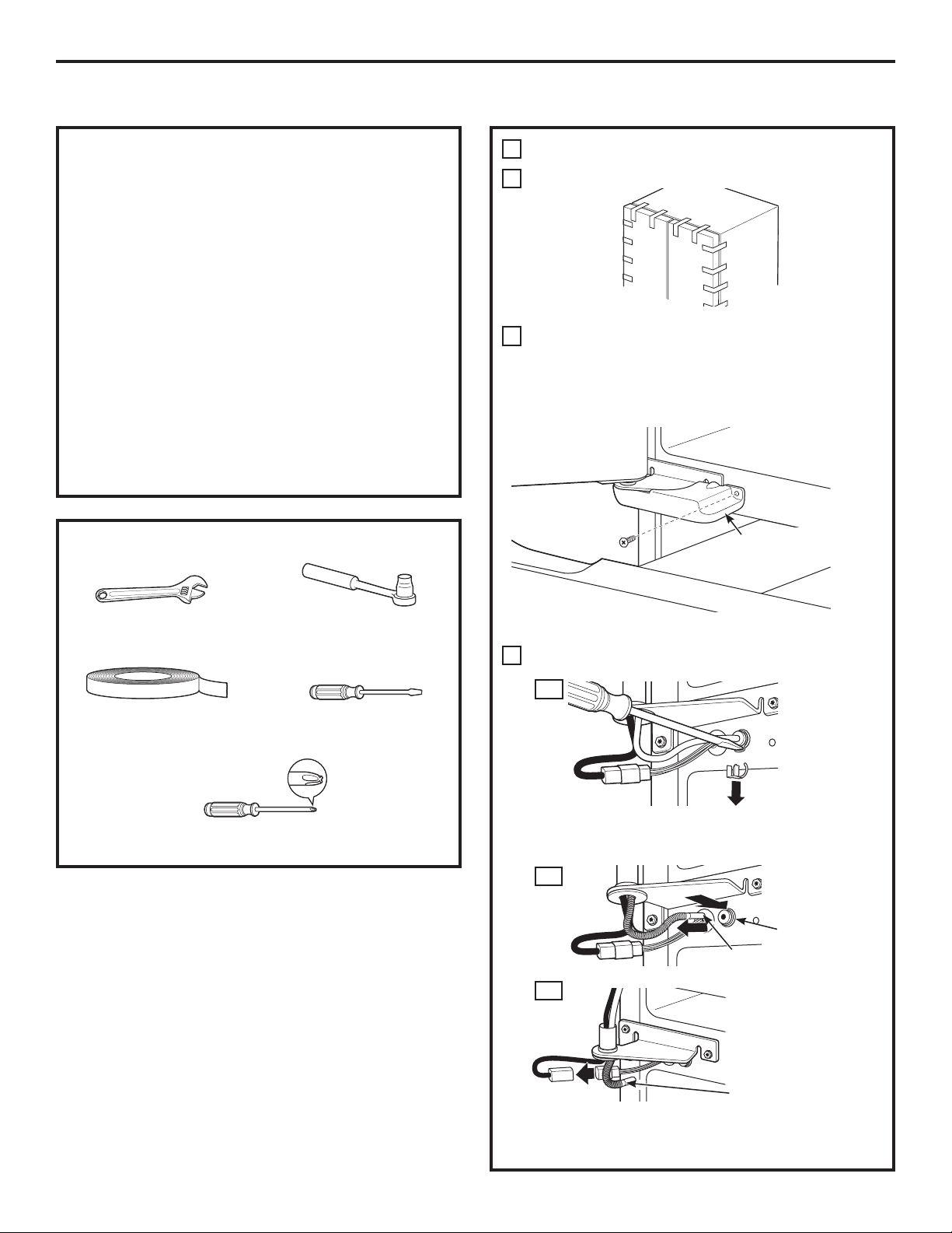
BEFORE YOU BEGIN
Read these instructions completely and carefully.
•
IMPORTANT ³ Save these instructions
for local inspector’s use.
•
IMPORTANT ³ Observe all governing
codes and ordinances.
•
Note to Installer – Be sure to leave these
instructions with the Consumer.
• Note to Consumer – Keep these instructions for
future reference.
• Skill level – Installation of this appliance requires
basic mechanical skills.
• Completion time –
Water Line Installation
• Proper installation is the responsibility of the
installer.
• Product failure due to improper installation is not
covered under the Warranty.
Refrigerator Installation
20 minutes
30 minutes
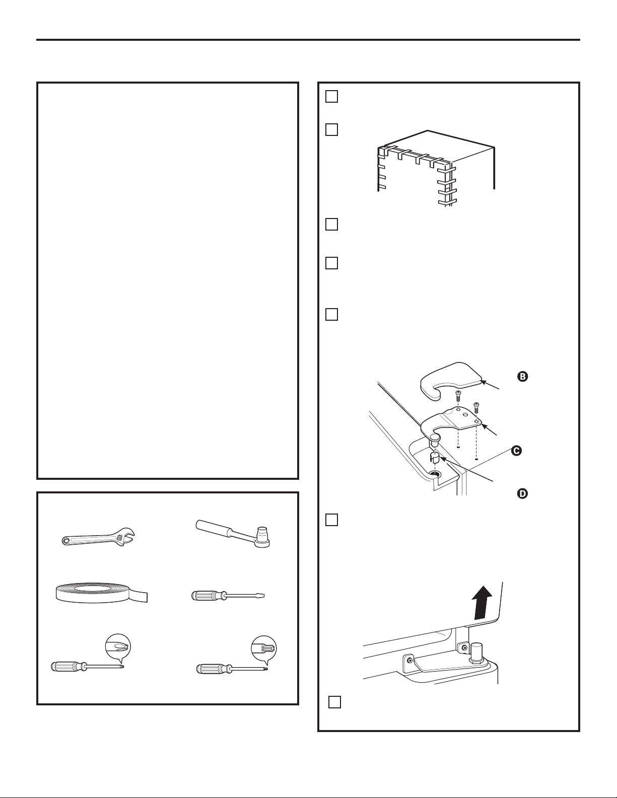
TOOLS YOU MAY NEED
Adjustable Wrench
1/4” Outer Diameter
Compression Nut
and Ferrule (sleeve)
(icemaker models only)
3/32”, 1/8” and 3/16” Allen
1/8” Drill Bit and
Electric or Hand Drill
Phillips Head Screwdriver
wrenches
3/8” and 5/16” S oc k e t
Ratchet/Driver
Tape measure
PREPARATION
MOVING THE REFRIGERATOR INDOORS
If the refrigerator will not fit through a doorway,
the refrigerator door and freezer drawer can be
removed.
• To remove the refrigerator door, see Step 1 in
the Reversing the Door Swing section.
• To remove the freezer drawer, see the Removing
the Freezer Drawer section.
WATER SUPPLY TO THE ICEMAKER AND
DISPENSER (ON SOME MODELS)
If the refrigerator has an icemaker, it will have to be
connected to a cold water line. A GE water supply
kit (containing tubing, shutoff valve, fittings and
instructions) is available at extra cost from your dealer,
by visiting our Website at GEAppliances.com (in
Canada at www.GEAppliances.ca) or from Parts and
Accessories, 800.626.2002 (In Canada .888.261.3055).
16
Pencil
Wire Cutters
1/4” Nut Driver
Level
Installation Instructions
INSTALLING THE REFRIGERATOR
REFRIGERATOR LOCATION
• Do not install the refrigerator where the temperature
will go below 60°F (16°C) because it will not run often
enough to maintain proper temperatures.
• Do not install the refrigerator where the temperature
will go above 100°F (37°C) because it will not perform
properly.
• Do not install the refrigerator in a location exposed to
water (rain, etc.) or direct sunlight.
• Install it on a floor strong enough to support it fully
loaded.
CLEARANCES
For clearance for ease of installation, proper air
circulation and plumbing and electrical, please refer to
the rating plate on the top left wall of the refrigerator.
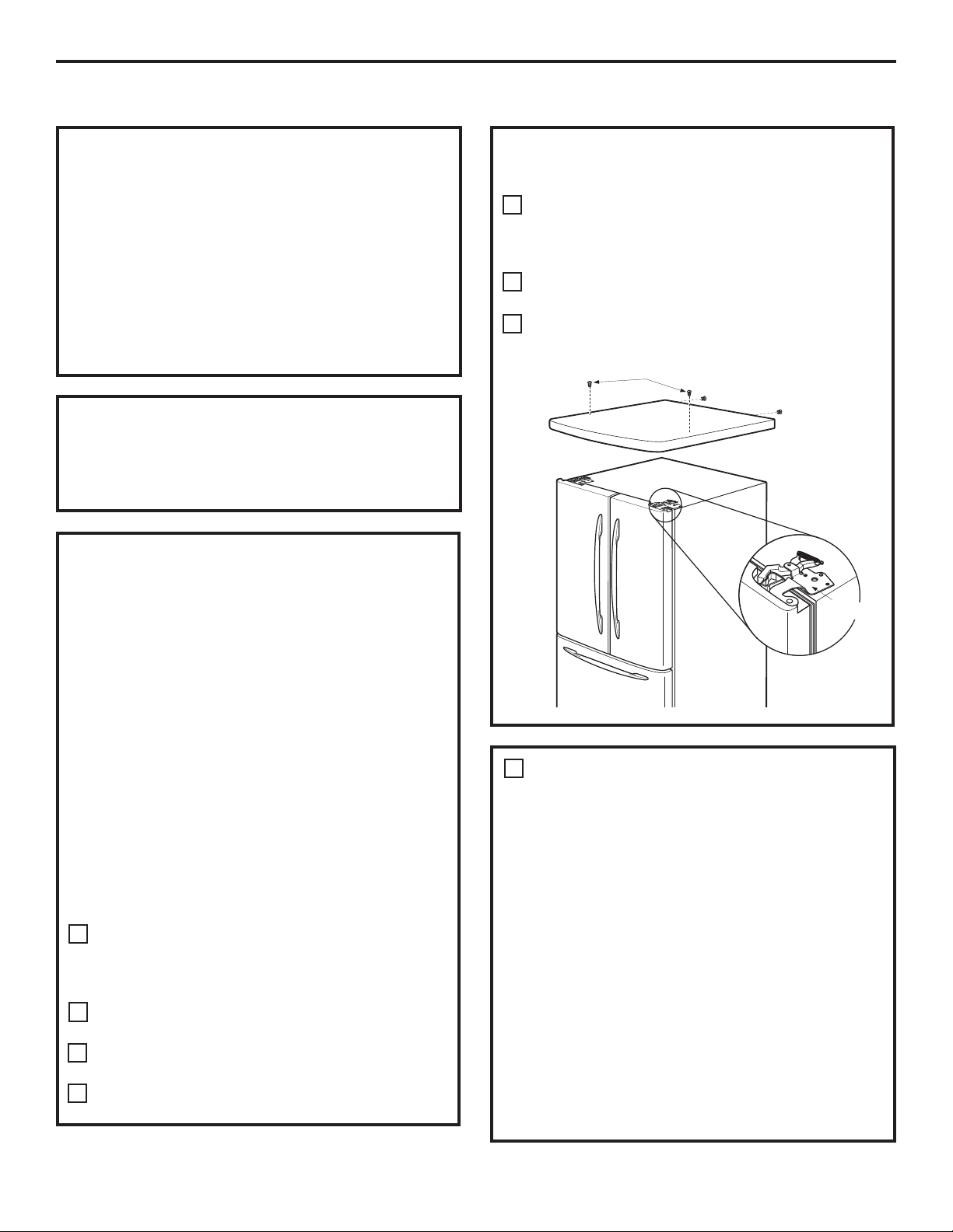
REMOVE TOP CAP (on some models)
• IMPORTANT NOTE: This refrigerator is 34-1/2” deep.
Doors and passageways leading to the installation
location must be at least 36” wide in order to leave
the doors and handles attached to the refrigerator
while transporting it into the installation location.
If passageways are less than 36”, the refrigerator
doors and handles can easily be scratched and
damaged. The top cap and doors can be removed
to allow the refrigerator to be safely moved indoors.
Start with Step A.
• If it is not necessary to remove doors, skip Step A.
Leave tape and all packaging on doors until the
refrigerator is in the final location.
• SKID REMOVAL: Tilt refrigerator to each side to
remove skid.
• NOTE: Use a padded hand truck to move this
refrigerator. Place the refrigerator on the hand truck
with a side against the truck. We strongly recommend
that TWO PEOPLE move and complete this installation.
Locate and remove the two Phillips head screws on
A
the top of the refrigerator. Remove the two screws
on each side at the rear of the top cap. Lift off and
remove top cap.
Remove the fresh-food door. Refer to Steps 1
B
through 3 of “Reversing the Door Swing” section.
Remove the bottom freezer drawer. Refer to
C
“Removing Freezer Drawer” section.
Move refrigerator to the installation location.
D
REMOVE TOP CAP (cont.) (on some models)
REINSTALL DOORS, DRAWERS AND TOP CAP
E
Carefully lower the door onto the center hinge.
Reinstall top hinge. NOTE: Ensure the door is properly
aligned to the case top to avoid readjustment of the
door during top cap reinstallation.
F
Place cap over the top of the refrigerator. Reinstall
the original screws in the top and back of the cap.
Reinstall the bottom freezer drawer. Refer to
G
“Replacing the Freezer Drawer” section.
A
Top Hinge B
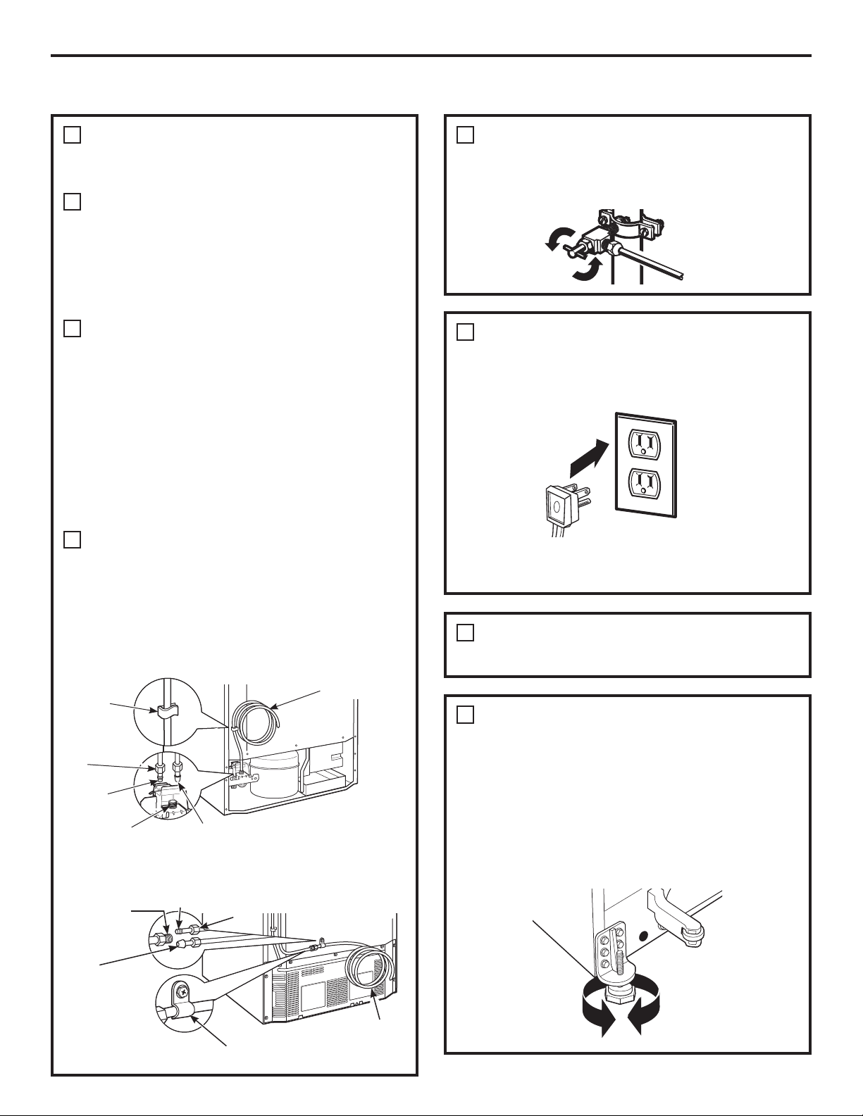
CONNECTING THE REFRIGERATOR
1
TO THE HOUSE WATER LINE
(icemaker and dispenser models)
A cold water supply is required for automatic
icemaker operation. If there is not a cold water
supply, you will need to provide one. See Installing
the Water Line section.
NOTES:
• Before making the connection to the refrigerator,
be sure the refrigerator power cord is not plugged
into the wall outlet.
• If your refrigerator does not have a water filter, we
recommend installing one if your water supply has
sand or particles that could clog the screen of the
refrigerator’s water valve. Install it in the water line
near the refrigerator. If using GE SmartConnect
Refrigerator Tubing Kit, you will need an additional
tube (WX08X10002) to connect the filter. Do not cut
plastic tube to install filter.
™
17
Installation Instructions
INSTALLING THE REFRIGERATOR (cont.)
CONNECTING THE REFRIGERATOR TO
1
THE HOUSE WATER LINE
(cont.)
If you are using copper tubing, place a
A
compression nut and ferrule (sleeve) onto the
end of the tubing coming from the house cold
water supply.
If you are using the GE SmartConnect
tubing, the nuts are already assembled to
the tubing.
If you are using copper tubing, insert
B
the end of the tubing into the refrigerator
connection, at the back of the refrigerator,
as far as possible. While holding the tubing,
tighten the fitting.
If you are using GE SmartConnect
insert the molded end of the tubing into the
refrigerator connection, at the back of the
refrigerator, and tighten the compression
nut until it is hand tight. Then tighten one
additional turn with a wrench. Overtightening
may cause leaks.
Fasten the tubing into the clamp provided to
C
hold it in position. You may need to pry open
the clamp.
™
™
tubing,
TURN ON THE WATER SUPPLY
2
(icemaker and dispenser models)
Turn the water on at the shutoff valve (house
water supply) and check for any leaks.
PLUG IN THE REFRIGERATOR
3
On models with an icemaker, before plugging
in the refrigerator, make sure the icemaker
power switch is set to the O (off) position.
See the grounding information attached to the
power cord.
One of the illustrations below will look like
the connection on your refrigerator.
Icemaker-Ready models
Tubing
Clamp
1/4”
Compression
Nut
Ferrule
(sleeve)
Refrigerator
Connection
SmartConnect
Tubing
™
1/4” Copper
Tubing
Icemaker-Installed Models
Refrigerator
Connection
SmartConnect™
Tubing
Ferrule
(sleeve)
1/4”
Compression
Nut
PUT THE REFRIGERATOR IN PLACE
4
Move the refrigerator to its final location.
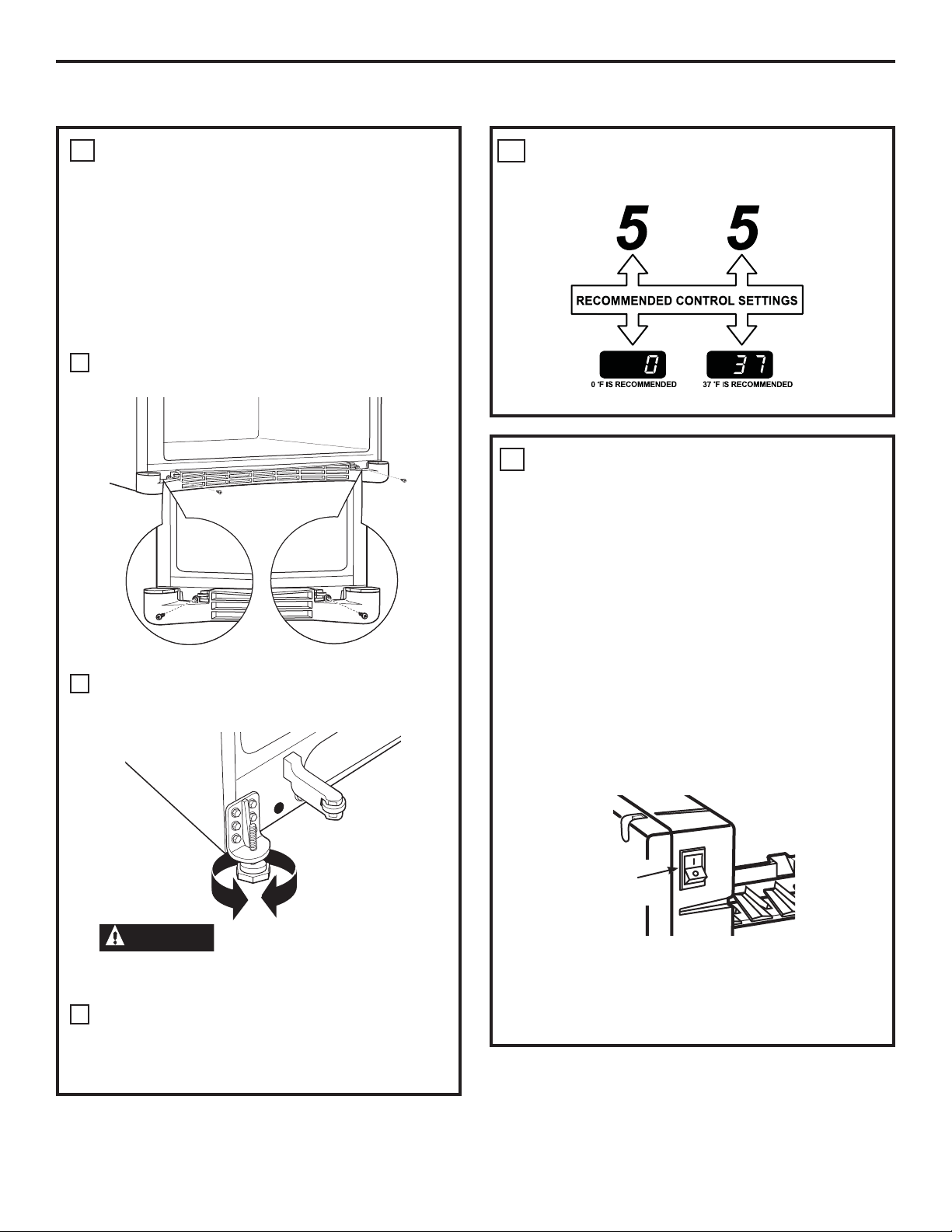
LEVEL THE REFRIGERATOR
5
Adjustable legs at the front corners of the
refrigerator should be set so the refrigerator is
firmly positioned on the floor, and the front is
raised just enough that the door closes easily
when opened about halfway.
To adjust the leveling legs, turn the
legs clockwise to raise the refrigerator,
counterclockwise to lower it.
Tubing Clamp
1/4” Tubing
18
Installation Instructions
REMOVE THE FRESH FOOD
6
DOOR HANDLE
(For placement in the installation location
or reversal of the handles – on some
models)
Stainless steel (on
some models):
REMOVING
THE DOOR
HANDLE: Loosen
the set screws
with the 3/32”
Allen wrench
and remove
the handle. NOTE:
For Double Door
models follow the
same procedure
on the opposite
door.
Plastic handle
(on some models):
REMOVING THE DOOR HANDLE: Depress the
tab on the underside of the handle and slide
the handle up and off of the mounting
fasteners.
REVERSING THE DOOR HANDLE (on some
models):
• Remove
the handle
mounting
fasteners with
a 3/16” Allen
wrench and
transfer
the handle
mounting
fasteners to
the right side.
• Remove the
logo badge.
• Remove and transfer the plug button to
the left side of the fresh food door. NOTE:
Use a flat plastic edge to prevent damaging
the door. Remove any adhesive on the door
with a mild detergent. Remove the paper
covering on the adhesive backing on
the logo badge prior to carefully attaching
the badge to the door.
A
B
Mounting
Fasteners
(appearance may vary)
B
A
Mounting
Fasteners
(appearance may vary)
Badge
Badge
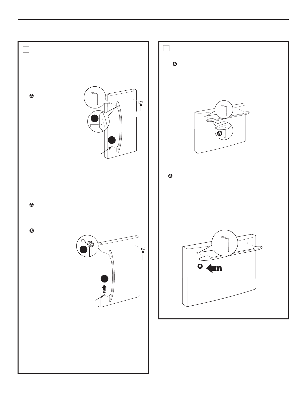
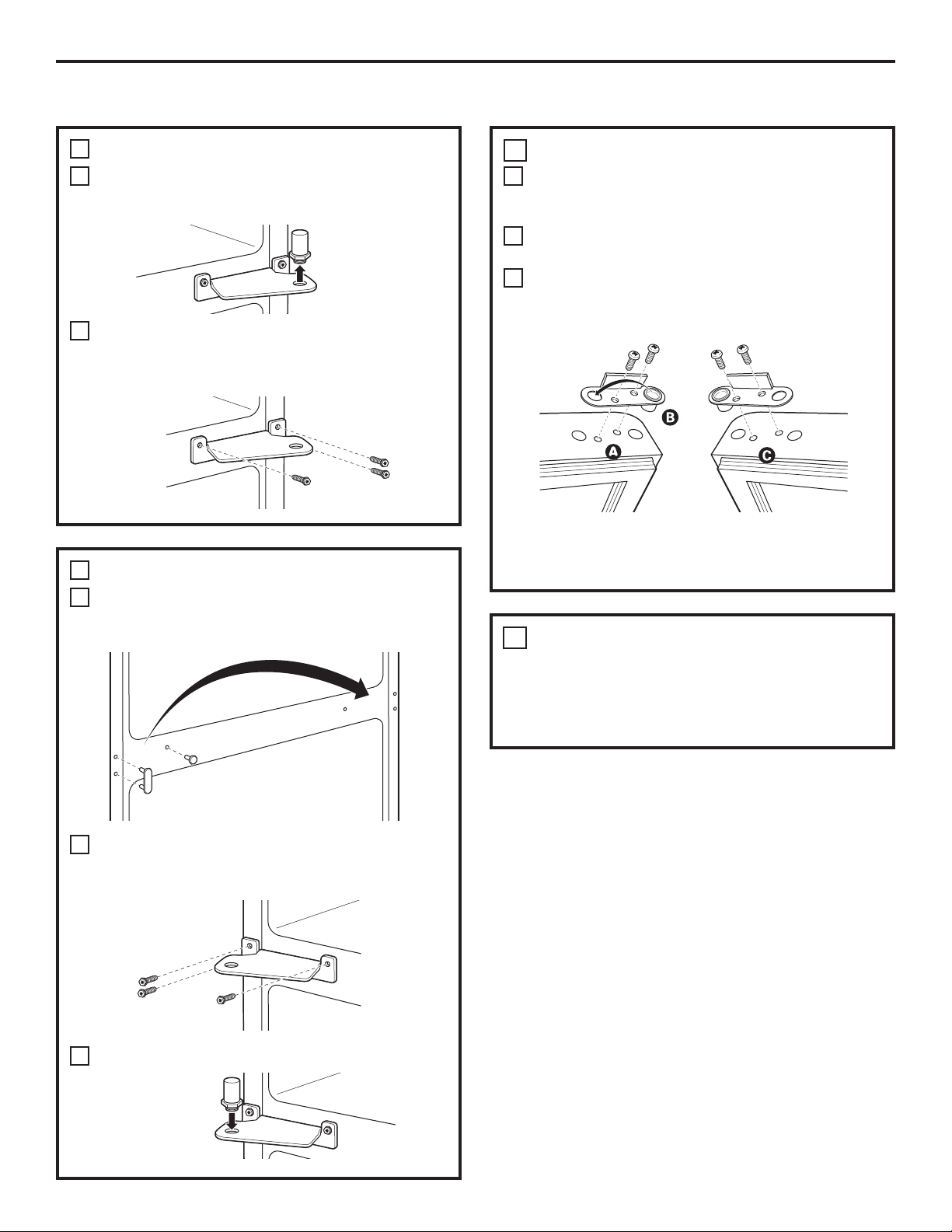
REMOVE THE FREEZER DOOR HANDLE
7
Stainless steel and plastic handles:
Loosen the set screws located on the
underside of the handle with the 1/8” Allen
wrench and remove the handle.
NOTE: If the handle mounting fasteners need
to be tightened or removed, use a 3/16” Allen
wrench.
(appearance may vary)
Plastic handle
(on some models):
REMOVING THE DOOR HANDLE: Depress the tab
on the underside left of the handle and slide the
handle left and off of the mounting fasteners.
Note: if the handle mounting fasteners need to be
tightened or removed use a 3/16” Allen wrench.
(appearance may vary)
19
Installation Instructions
INSTALLING THE REFRIGERATOR (cont.)
ATTACH THE FREEZER DOOR HANDLE
ATTACH THE FRESH FOOD
8
DOOR HANDLE
Stainless steel handle:
Attach the
handle to the
handle mounting
fasteners and
tighten the set
screws with a
3/32” Allen
wrench.
NOTE: For
Double Door
models follow
the same
procedure on the
opposite door.
Plastic handle:
Attach the handle to the handle mounting
fasteners by aligning the slots with the
handle mounting fasteners.
Slide it down until it is firmly locked into
position.
A
Mounting
Fasteners
(appearance may vary)
9
Stainless steel and plastic handles:
Plastic handle: (on some models)
Attach the handle to the handle mounting
fasteners by aligning the slots with the handle
mounting fasteners.
Slide it right until it is firmly locked into position.
Attach the handle firmly to the mounting
fasteners and tighten the set screws on
the bottom of the handle with a 1/8” Allen
wrench.
(appearance may vary)
Slots on back
of handle
Slots on back of
handle
Mounting
fasteners
NOTE: Before attaching the
handle, make sure the tab is
oriented as shown.
(appearance may vary)
(appearance may vary)
20
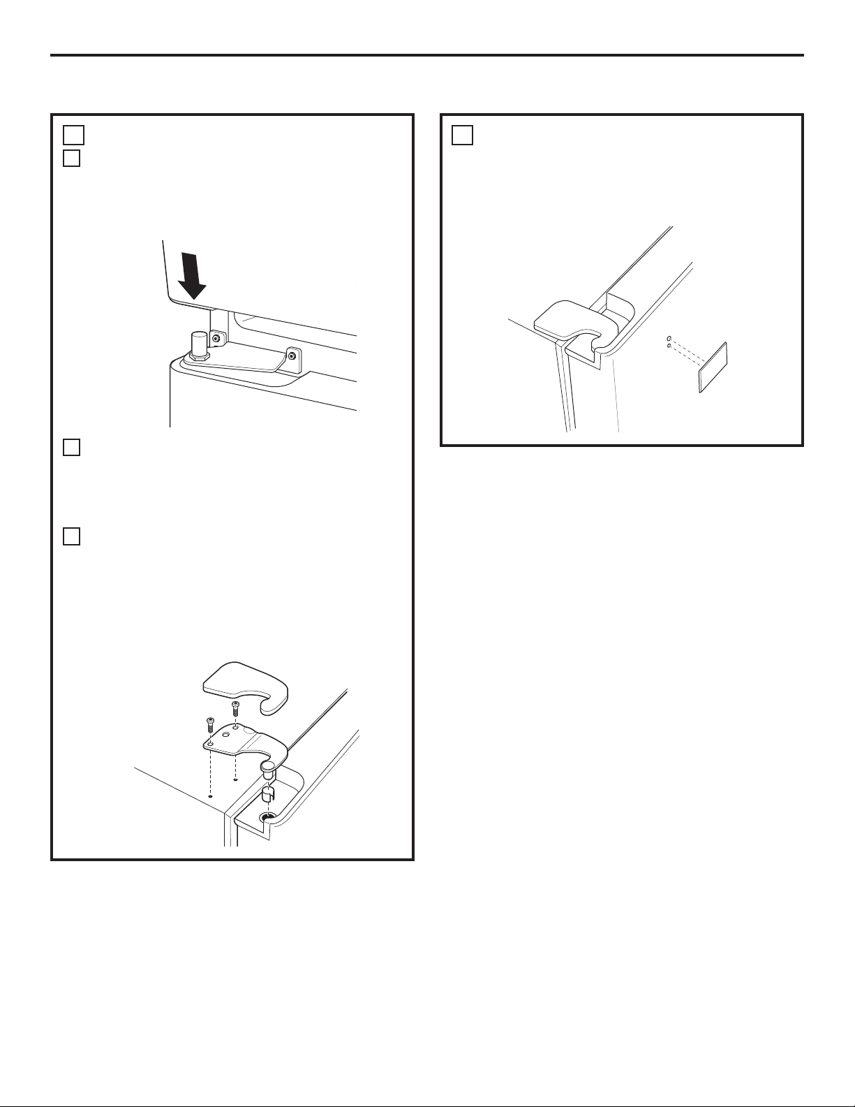
Installation Instructions
LEVEL THE REFRIGERATOR
10
The leveling legs have 2 purposes:
1) Leveling legs adjust so the refrigerator is
firmly positioned on the floor and does not
wobble.
2) Leveling legs serve as a stabilizing brake
to hold the refrigerator securely in position
during operation and cleaning. The leveling
legs also prevent the refrigerator from
tipping.
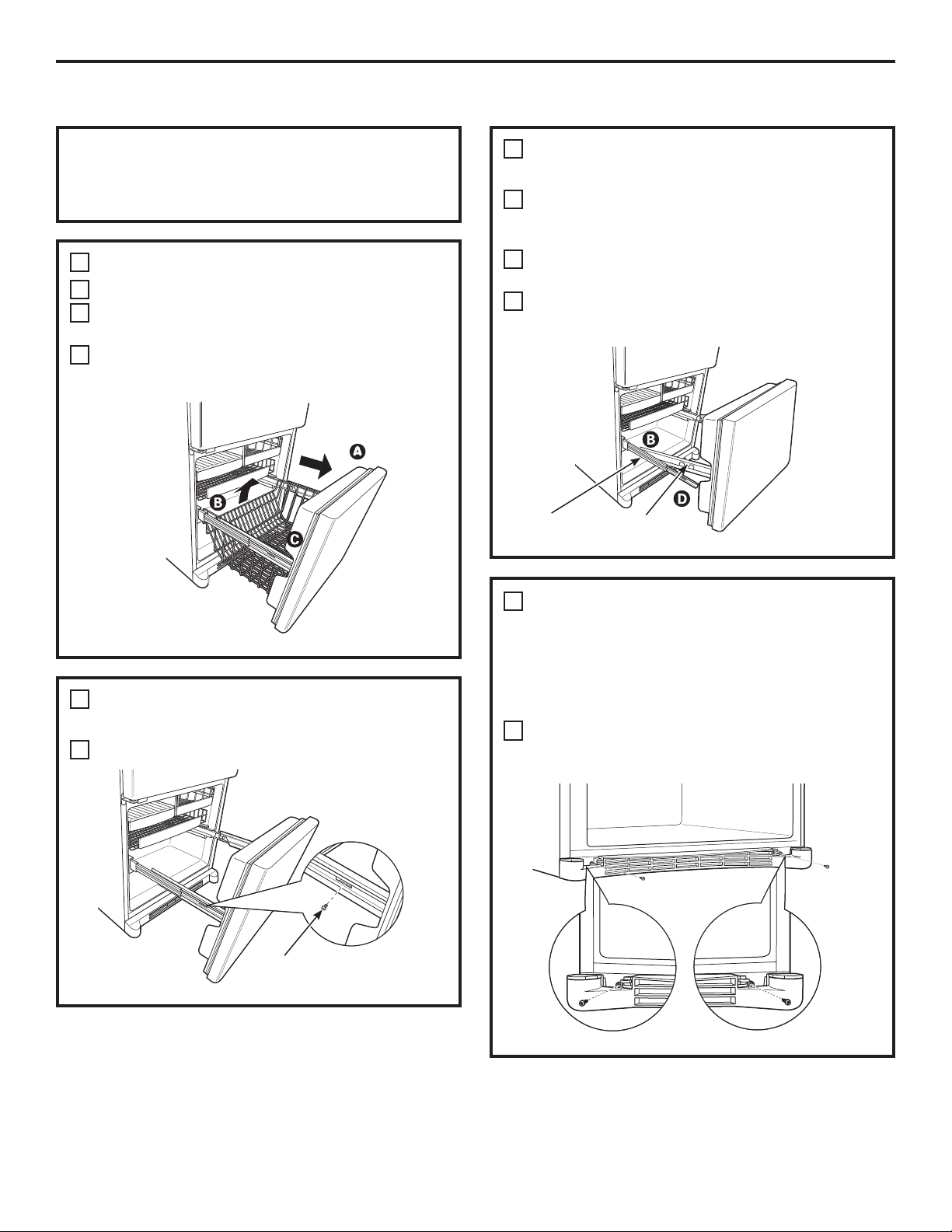
Remove the grille by removing the two Phillips
A
head screws.
SET THE CONTROLS
11
Set the controls to the recommended setting.
REMOVE PACKAGING, START
12
ICEMAKER
(icemaker models)
A) Remove all tape, foam and protective
packing from shelves and drawers.
B) Remove the tie downs from the freezer
baskets.
C) Place half width basket onto drawer
slides. See About the freezer section for
instructions.
Turn the leveling legs clockwise to raise
B
the refrigerator, counterclockwise to lower it.
CAUTION
injury or property damage, the leveling legs
must be firmly touching the floor.
Replace the base grille by inserting the two
C
Phillips head screws.
To avoid possible personal
Set the icemaker power switch to the I (on)
position. The icemaker will not begin to operate
until it reaches its operating temperature of
15°F (–9°C) or below. It will then begin operation
automatically. It will take 2–3 days to fill the
ice bin.
Power
switch
NOTE:
In lower water pressure conditions, the water
valve may turn on up to 3 times to deliver
enough water to the icemaker.
21
Installation Instructions
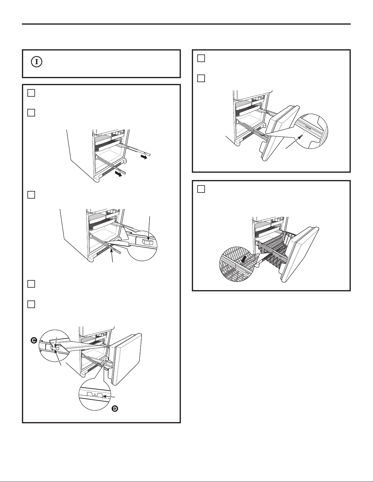
REMOVING THE FREEZER DRAWER
The freezer drawer can be removed, if needed,
to fit through tight areas.
Read these instructions completely and carefully.
REMOVE THE BASKET
1
Open the freezer drawer until it stops.
A
The freezer basket rests on a frame inside the
B
freezer drawer. Lift the basket up at the back.
Lift the front up and lift the entire basket up
C
and out of the drawer.
REMOVE THE DRAWER FRONT FROM
2
THE SLIDES
Lift up on both sides of the freezer drawer
B
handle to separate the drawer railings from
the rail assemblies.
C
Set the drawer front on a non-scratching
surface.
D
Push the rail assemblies back into locking
position.
Rail Assembly
(cont.)
Drawer
Assembly
REMOVE THE DRAWER FRONT
2
FROM THE SLIDES
Remove the screw on each side of the railing.
A
Screw
REMOVE THE BASE GRILLE
3
(if needed)
If, after removing the freezer drawer and
refrigerator door, the refrigerator will still not
fit through a doorway, the base grille can be
removed.
Remove the base grille by removing the screws.
A
22
Installation Instructions
Two people may be required to complete
this procedure.
ATTACH AND SECURE THE DRAWER
1
FRONT TO THE SLIDES
Pull out the rail assemblies to the full length
A
on each side of the cabinet.
Locate the slots on the inside of the rail
B
assemblies near the back.
Slot
ATTACH AND SECURE THE DRAWER
1
FRONT TO THE SLIDES
Replace the screws on both rail assemblies.
E
REPLACE THE FREEZER BASKET
2
Replace the lower freezer basket by lowering it
into the frame.
(cont.)
Screw
Rail assembly
C
Insert the hooks at the back of the drawer
railings into the slots on the rail assemblies.
Lower the front of the drawer, making sure the
D
tabs on the sides of the railings fit into the front
slots in the rail assemblies.
Hook
Slot
Tab
23
Installation Instructions
REVERSING THE DOOR SWING (Single Door Refrigerator Models only)
REMOVE THE REFRIGERATOR DOOR
IMPORTANT NOTES
When reversing the door swing:
NOTE: Door swing is not reversible on stainless
steel models.
• Read the instructions all the way through before
starting.
• Parts are included in the door hinge kit.
• Handle parts carefully to avoid scratching paint.
• Set screws down by their related parts to avoid
using them in the wrong places.
• Provide a non-scratching work surface for
the doors.
IMPORTANT: Once you begin, do not move the
cabinet until door-swing reversal is completed.
These instructions are for changing the hinges
IURPWKHULJKWVLGHWRWKHOHIWVLGH³LI\RXHYHUZDQW
to change the hinges back to the right side, follow
these same instructions and reverse all references
to left and right.
• Once door swing is finalized, ensure the logo
badge is properly aligned and permanently
secured to the door by removing the adhesive
cover on the back side. NOTE: A replacement
logo badge is included in the hinge kit.
Unplug the refrigerator from its electrical outlet.
Empty all door shelves, including the dairy
compartment.
1
Tape the door shut with masking tape.
A
B
Remove the hinge cover on top of the
refrigerator door by carefully prying it up with a
putty knife, if necessary.
C
Using a 5/16” socket ratchet/driver, remove
the bolts securing the top hinge to the cabinet.
Then lift the hinge straight up to free the hinge
pin from the socket in the top of the door.
D
Carefully remove the door thimble from inside
the socket. This will be used again when
reinstalling the door on the other side.
Hinge Cover
Top Hinge
TOOLS YOU WILL NEED
Adjustable Wrench
Masking Tape
Phillips Screwdriver
5/16” Socket Ratchet/
Driver
Thin-blade Screwdriver
Torx T-20 Driver
24
Door Thimble
E
Remove the tape and tilt the door away from
the cabinet. Lift the door off the center hinge
pin. Ensure that the plastic hinge pin thimble
remains on the hinge pin or inside door hinge
pin hole located in the bottom of the door.
F
Set the door on a non-scratching surface with
the inside up.
Installation Instructions
REMOVE CENTER HINGE
2
Remove the hinge pin from the hinge bracket.
A
The hinge pin will be used again with the new
hinge bracket for the other side.
Using a 5/16” socket ratchet/driver, remove the
B
bolts securing the center hinge to the cabinet.
Set the bolts aside.
INSTALL CENTER HINGE
3
Transfer the plug button and screw hole cover
A
in the hinge holes on the left side to the right
side.
TRANSFER REFRIGERATOR DOOR STOP
4
Remove the door stop on right side of the
A
bottom of the refrigerator door by removing
the two screws.
B
Move the plastic hinge hole thimble to the
opposite hole.
C
Install the door stop on the left side, making
sure to line up the screw holes in the door stop
with the holes in the bottom of the door.
Bottom of
Refrigerator Door
(Right Side)
TRANSFER REFRIGERATOR
5
Bottom of
Refrigerator Door
(Left Side)
DOOR HANDLE TO RIGHT
Refer to Remove the Fresh Food Door Handle
and Attach the Fresh Food Door Handle
sections for instructions.
A new hinge bracket is required for the left
B
side (supplied in the door hinge kit). Install the
center hinge from the kit on the left side.
Install the hinge pin into the new hinge bracket.
C
25
Installation Instructions
REVERSING THE DOOR SWING (cont.)
REHANG REFRIGERATOR DOOR
6
Lower the refrigerator door onto the center
A
hinge pin. Ensure that the plastic hinge pin
thimble is on the center hinge pin or inside
door hinge pin hole located in the bottom
of the door.
Insert the door thimble into the hinge hole on
B
top of the refrigerator door and then insert the
top hinge pin. Make sure the door is aligned
with the cabinet. Attach the hinge to the top of
the cabinet loosely with the bolts.
Make sure the gasket on the door is flush
C
against the cabinet and is not folded. Support
the door on the handle side and make sure the
door is straight and the gap between the doors
is even across the front. While holding the door
in place, tighten the top hinge bolts. Replace
the hinge cover.
INSTALL THE LOGO BADGE
7
Remove the adhesive backing paper and align
the pins on the back of the badge with the
holes in the door. Apply pressure to the badge
to ensure it sticks to the door.
26
Installation Instructions
REMOVING THE DOORS (Double Door Refrigerator Models only)
REMOVE THE REFRIGERATOR DOORS
IMPORTANT NOTES
NOTE: Door swing is not reversible.
• Read the instructions all the way through before
starting.
• Handle parts carefully to avoid scratching paint.
• Set screws down by their related parts to avoid
using them in the wrong places.
• Provide a non-scratching work surface for
the doors.
IMPORTANT: Once you begin, do not move
the cabinet.
These instructions are for removing the doors.
Unplug the refrigerator from its electrical outlet.
Empty all door shelves, including the dairy
compartment.
1
Tape the doors shut with masking tape.
A
(for water dispenser models)
B
Start with left-hand door first: Remove the
screw securing the center hinge cover, lift the
hinge cover and place to the side on top of the
refrigerator.
TOOLS YOU WILL NEED
Adjustable Wrench
Masking Tape
Phillips Screwdriver
3/8” and 10 mm Socket
Ratchet/Driver
Thin-blade Screwdriver
Remove hinge cover
(1 Phillips screw)
(for water dispenser models)
C
Remove water coupling and power coupling.
C1
Water Coupling
Remove the metal
spring clip. Use a
screwdriver to push
the red plastic locking
clip down and off.
C2
Water Coupling
Push red collar
Pull tube.
and hold.
27
C3
Pull apart
power coupling
to disconnect
Power Coupling
Black mark
flush with
collar assembly
Installation Instructions
REMOVING THE DOORS (cont.)
REMOVE THE REFRIGERATOR DOORS
1
(cont.)
Remove the hinge cover on top of the
D
refrigerator door by removing the Phillips head
screw and pulling it up.
Using a 5/16” socket ratchet/driver, remove
E
the bolts securing the top hinge to the cabinet.
Then lift the hinge straight up to free the hinge
pin from the socket in the top of the door.
Hinge Cover
Top Hinge
REMOVE CENTER HINGE
2
Using a 5/16” socket ratchet/driver, remove the
bolts securing the center hinge to the cabinet.
Set the hinge and bolts aside.
REMOVE OPPOSITE DOOR
3
Follow the same procedure on the opposite
door. There are no wires, water lines or center
hinge covers on the opposite side.
REMOVE FREEZER DRAWER
4
Refer to the Removing the Freezer Drawer
section for instructions.
Remove the tape and tilt the door away from
F
the cabinet. Lift the door off the center hinge
pin. Ensure that the plastic hinge pin thimble
remains on the hinge pin or inside door hinge
pin hole located in the bottom of the door.
Set the door on a non-scratching surface with
G
the inside up.
28
Installation Instructions
REPLACING THE DOORS (Double Door Refrigerator Models only)
INSTALL CENTER HINGE
1
Install the center hinge on each side.
REHANG REFRIGERATOR DOORS
2
Lower the refrigerator door onto the center
A
hinge pin. Ensure that the plastic hinge pin
thimble is on the center hinge pin or inside
door hinge pin hole located in the bottom
of the door.
Hinge Pin
Securely tape the door shut with masking tape
B
or have a second person support the door.
C
Route wires through bottom left hinge pin slot.
Insert the top hinge pin into the hinge hole
on top of the refrigerator door. Make sure the
door is aligned with the cabinet and opposite
door. Attach the hinge to the top of the cabinet
loosely with the bolts.
REHANG REFRIGERATOR DOORS (CONT.)
2
Make sure the gasket on the door is flush
E
against the cabinet and is not folded. Make
sure the door is straight and the gap between
the doors is even across the front. While
holding the aligned door in place, tighten
the top hinge bolts. Replace the hinge cover
and screw.
Hinge Cover
Top Hinge
Bolts
(appearance may vary)
REPLACE OPPOSITE DOOR
3
Follow the same procedure on the opposite
door. There is no water line or hinge cover.
ALIGN DOUBLE DOORS
4
If the top of the doors are uneven, first try to
raise the lowest door by turning the leveling leg
on the same side as the door until the doors
are even. If the unit rocks, re-adjust the leveling
legs to the extent that the unit is stable.
Bottom
Left Hinge
Pin Slot
(appearance may vary)
On left-hand doors, pass the wires and water
D
line through the center hinge pin. Then connect
the water line and 4-pin connector.
Center Hinge Pin
4-Pin
Connector
Water Line
29
If the doors remain uneven, turn the adjustable
pin to raise, or lower, the left door to match
the right door. Use a 1/4” Allen wrench to turn
the pin.
Adjustable pin
REPLACE FREEZER DRAWER
5
Refer to the Replacing the Freezer Drawer
section for instructions.
Installation Instructions
INSTALLING THE WATER LINE (ICEMAKER MODELS)
BEFORE YOU BEGIN
Recommended copper water supply kits are
WX8X2, WX8X3 or WX8X4, depending on the
amount of tubing you need. Approved plastic
water supply lines are GE SmartConnect
Refrigerator Tubing (WX08X10006, WX08X10015
and WX08X10025).
When connecting your refrigerator to a GE Reverse
Osmosis Water System, the only approved
installation is with a GE RVKit. For other reverse
osmosis water systems, follow the manufacturer’s
recommendations.
If the water supply to the refrigerator is from
a Reverse Osmosis Water Filtration System
AND the refrigerator also has a water filter,
use the refrigerator’s filter bypass plug. Using
the refrigerator’s water filtration cartridge in
conjunction with the RO filter can result in hollow
ice cubes.
This water line installation is not warranted by
the refrigerator or icemaker manufacturer. Follow
these instructions carefully to minimize the risk of
expensive water damage.
Water hammer (water banging in the pipes) in
house plumbing can cause damage to refrigerator
parts and lead to water leakage or flooding. Call a
qualified plumber to correct water hammer before
installing the water supply line to the refrigerator.
To prevent burns and product damage, do not hook
up the water line to the hot water line.
If you use your refrigerator before connecting
the water line, make sure the icemaker power
switch is in the O (off) position.
Do not install the icemaker tubing in areas where
temperatures fall below freezing.
When using any electrical device (such as a power
drill) during installation, be sure the device is double
insulated or grounded in a manner to prevent the
hazard of electric shock, or is battery powered.
All installations must be in accordance with local
plumbing code requirements.
™
WHAT YOU WILL NEED
• Copper or GE SmartConnect™ Refrigerator
Tubing kit, 1/4” outer diameter to connect the
refrigerator to the water supply. If using copper,
be sure both ends of the tubing are cut square.
To determine how much tubing you need: measure
the distance from the water valve on the back
of the refrigerator to the water supply pipe.
Be sure there is sufficient extra tubing to allow
the refrigerator to move out from the wall after
installation.
GE SmartConnect
are available in the following lengths:
8’ (2.4 m) – WX08X10006
15’ (4.6 m) – WX08X10015
25’ (7.6 m) – WX08X10025
™
Refrigerator Tubing Kits
30
 Loading...