

GE PFIC1NFYCWV, PFIC1NFYCBV, PFIC1NFYAWV, PFIC1NFYABV Owner’s Manual
0
GEAppliances.com
L_
0
0
Safety Instructions ........... 2,3
Operating Instructions
Additional Features ................. 8
Automatic Icemaker ............... 11
Care and Cleaning ............. 12-13
Controls .......................... 4-5
Crispers and Pans ................... 9
Freezer ............................ 10
Replacing the Light Bulbs .......... 14
Shelves and Bins .................. 7, 8
Water Filter ......................... 6
Installation Instructions
Installing the Anti-Tip
Floor Bracket .................. 18-19
Installing the Refrigerator ....... 20-24
Installing the Water Line ........ 33-35
Preparing to Install
the Refrigerator .................... 17
Removing and Replacing the
Freezer Drawer ................. 25, 26
Reversing the Door Swing
(Single Door Refrigerator
Models onlg) ................... 27-29
Removing and Replacing
the Doors (Double Door
Refrigerator Models only) ....... 30-32
Trim Kits and Decorator
Panels ......................... 15-16
Models 21 and 25
Cong61ateur inf6rieur
R frig rateurs
La section frangaise commence 6 la page 45
Congelador inferior
Refrigeradores
La secci6n en espa_ol empieza en la p6gina 89
I.m
4.-
Troubleshooting Tips ...... 36-4o
Normal Operating Sounds .......... 36
Consumer Support
Consumer Support ........ Back Cover
Performance Data Sheet ........... 43
State of California Water
Treatment Device Certificate ....... 44
Warrantg for Canadian
Customers ......................... 42
Warrantg for U.S. Customers ....... 41
Write the model and serial
numbers here:
Nodel #
Serial #
Find these numbers on a label
on the right side, near the top of the
refrigerator compartment.
200D9366PO07 49-60580 01-09JR

IMPORTANTSAFETYINFORMATION.
READALL INSTRUCTIONSBEFOREUSING.
WARNING!
Use this appliance only for its intended purpose as described in this Owner's Manual.
SAFETYPRECAUTIONS
When using electrical appliances, basic safety precautions should be followed, including the following:
_,This refrigerator must be properly installed
and located in accordance with the Installation
Instructions before it is used.
Donot allowchildrento climb,stand or hang
on the shelves in the refrigerator.They could
damage the refrigerator and seriousluinjure
themselves.
Donot touch the cold surfaces in the freezer
compartment when hands are damp or wet.
Skinmay stickto these extremely cold surfaces.
Donot storeor use gasolineor other flammable
vapors and liquidsin the vicinity ofthis or any other
appliance.
Keepfingers out of the "pinch point" areas;
clearances between the doors and between the
doors and cabinet are necessarilusmall.Becareful
closing doors when children are in the area.
_:,Inrefrigerators with automatic icemakers,avoid
contact with the moving parts of the ejector
mechanism, or with the heating element that
releasesthe cubes.Do not placefingers orhands
on the automatic icemaking mechanism while the
refrigerator is plugged in.
Unplugthe refrigerator before cleaning and making
repairs.
NOTE:Westrongly recommend that any servicing
be performed by a qualifiedindividua!.
_,Setting either or both controlsto O(off) does
not remove power to the light circuit.
Donot refreezefrozen foods which have
thawed completely.
Ai,DANGER! RISK OF CHILD ENTRAPMENT
PROPERDISPOSAL OF THE REFRIGERATOR
Childentrapment and suffocation are not problems of
the past. Junked or abandoned refrigerators are still
dangerous...evenif they will sit for "just afew days." If
you aregetting rid of your old refrigerator,please
follow the instructions below to help prevent
accidents.
Before You Throw Away Your Old
Refrigerator or Freezer:
Take off the doors.
Leavethe shelvesin place sothat children may not
easily climb inside.
Refrigerants
All refrigeration products contain refrigerants,
which under federal law must be removed prior to
product disposal. If you are getting rid of an old
refrigeration product, check with the company
handling the disposal about what to do.
USEOF EXTENSION CORDS
Because of potential safetg hazards under certain conditions, we stronglg recommend against
the use of an extension cord.
However,if you must usean extension cord, it isabsolutely necessarythat it be a UL-listed (inthe United States)
or a CSAcertified (in Canada),]-wire grounding type appliance extension cord having a grounding type plug
and outlet andthat the electrical rating of the cord be 15amperes(minimum)and 120 volts.
GEAppliunces.com
WARNING!
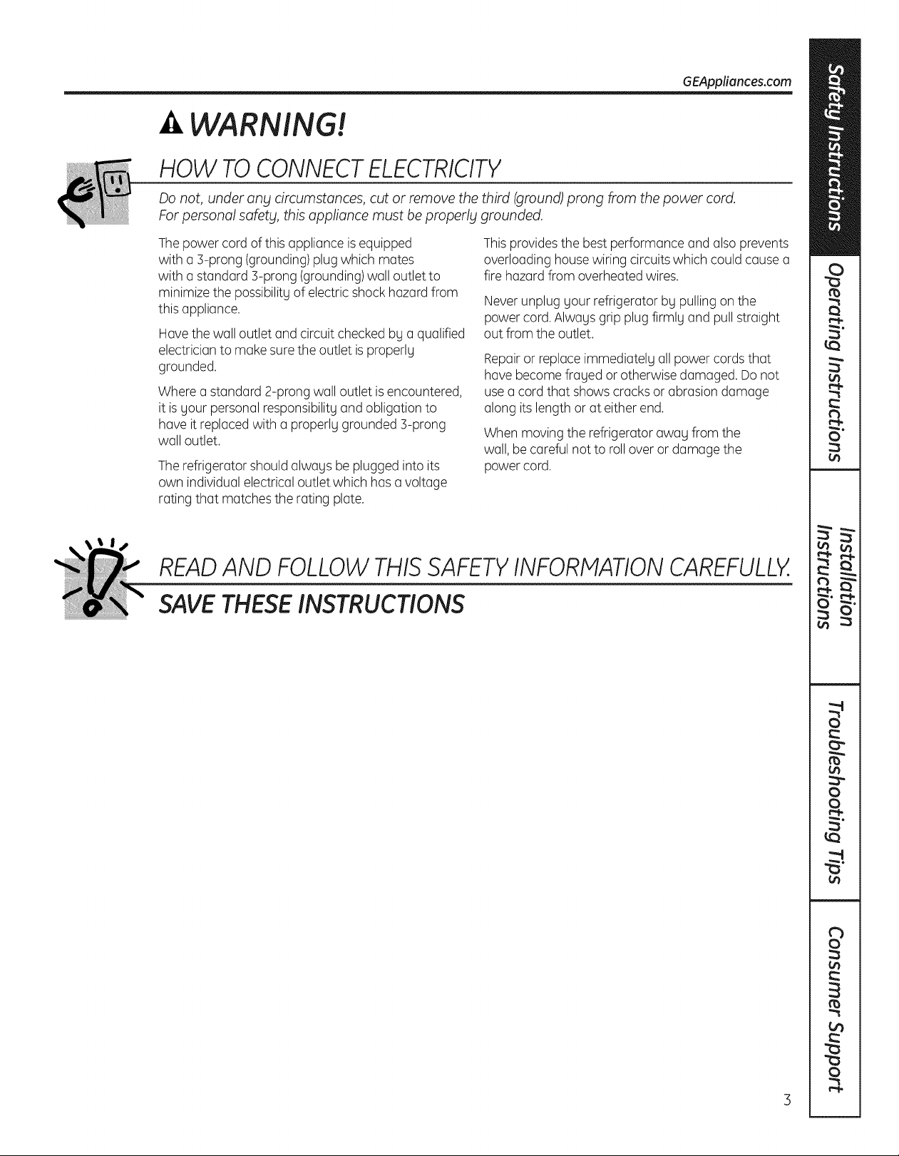
HOW TO CONNECT ELECTRICITY
Do not, under an_l circumstances, cut or remove the third (ground) prong from the power cord.
For personal safet_l, this appliance must be properlbt grounded.
Thepower cord of this appliance isequipped
with a 3-prong (grounding)plug which mates
with a standard 3-prong (grounding)wall outlet to
minimize the possibility of electricshock hazard from
this appliance.
Have the wall outlet and circuit checked by a qualified
electrician to make surethe outlet isproperly
grounded.
Where a standard 2-prong wall outlet isencountered,
it isyour personalresponsibility and obligation to
have it replacedwith a properly grounded 3-prong
wall outlet.
The refrigerator should always be plugged into its
own individual electricaloutlet which hasavoltage
rating that matches the rating plate.
This provides the best performance and also prevents
overloading housewiring circuits which could cause a
fire hazard from overheatedwires.
Never unplug your refrigerator by pulling on the
power cord. Always gripplug firmly and pullstraight
out from the outlet.
Repairor replaceimmediately all power cords that
have become frayed or otherwise damaged. Do not
usea cord that showscracks or abrasion damage
along its length or at either end.
When moving the refrigerator away from the
wall, be careful not to rollover or damagethe
power cord.
READAND FOLLOWTHISSAFETYINFORMATIONCAREFULLY.
SAVETHESEINSTRUCTIONS
(onsome models)
[]
[]
[] []
Hold 3 seconds to reset Hold 3 seconds
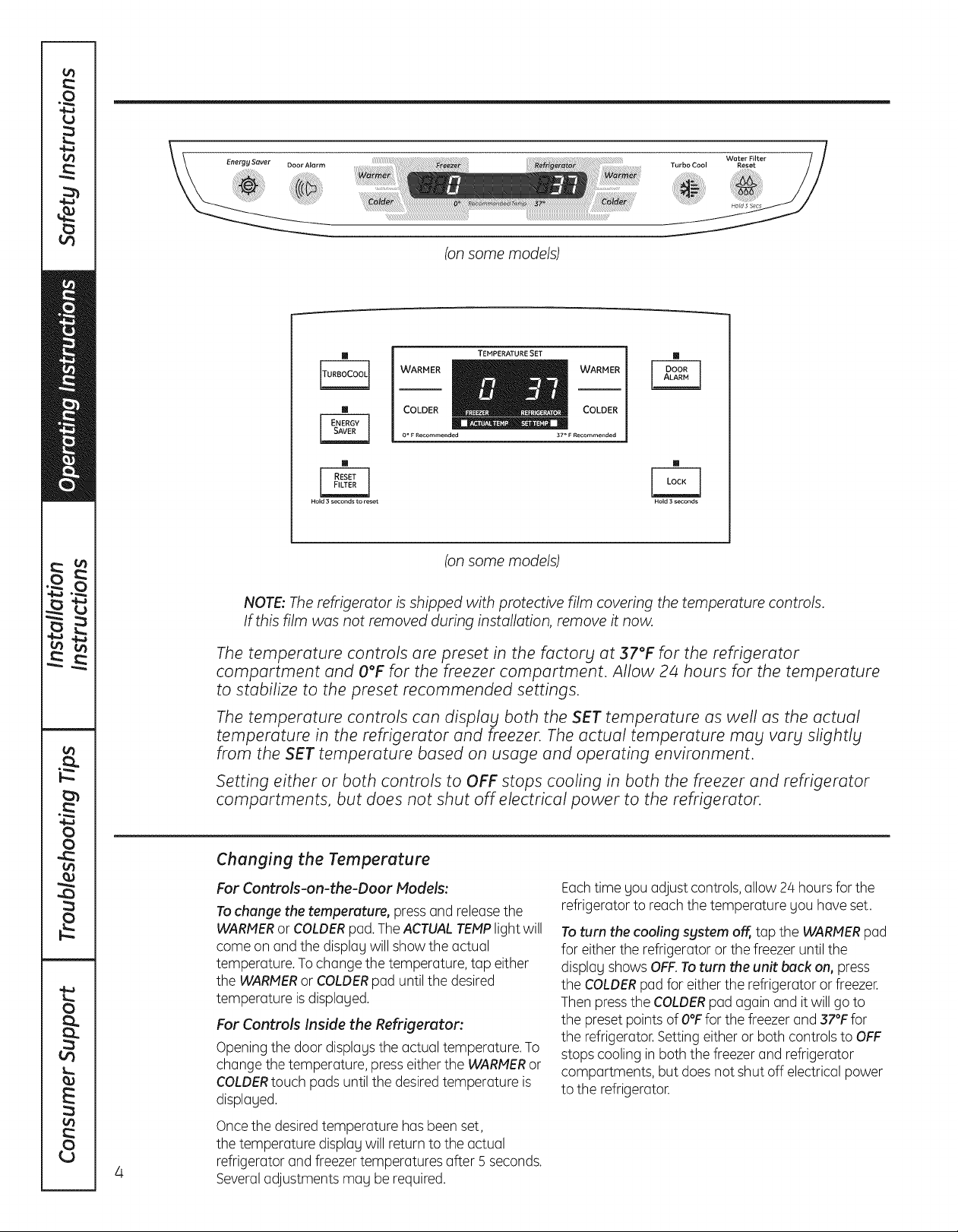
WARMER _WARMER
COLDER COLDER
0oFRecommended 37° F Recommended
TEMPERATURE SET
[]
(on some models)
NOTE: The refrigerator is shipped with protective film covering the temperature controls.
If this film was not removed during installation, remove it now.
The temperature controls are preset in the factory at 37°F for the refrigerator
compartment and O°Ffor the freezer compartment. Allow 2/4hours for the temperature
to stabilize to the preset recommended settings.
The temperature controls can display both the SET temperature as well as the actual
temperature in the refrigerator and freezer. The actual temperature may vary slightly
from the SET temperature based on usage and operating environment.
Setting either or both controls to OFF stops cooling in both the freezer and refrigerator
compartments, but does not shut off electrical power to the refrigerator.
Changing the Temperature
For Controls-on-the-Door Models:
Tochange the temperature, pressand releasethe
WARMERor COLDERpad.TheACTUALTEMPlight will
come on andthe display will show the actual
temperature. To change the temperature, tap either
the WARMERorCOLDERpad until the desired
temperature isdisplayed.
For Controls Inside the Refrigerutor:
Opening the door displags the actual temperature. To
change the temperature, presseither the WARMERor
COLDERtouch pads untilthe desiredtemperature is
displaged.
Oncethe desiredtemperature has been set,
the temperature displag will return to the actual
4
refrigerator and freezertemperatures after 5 seconds.
Severaladjustments mag be required.
Eachtime gou adjust controls,allow 24 hours for the
refrigerator to reachthe temperature gou have set.
Toturn the cooling system off, tap the WARMERpad
for either the refrigerator or the freezer until the
displag shows OFF.Toturn the unit back on, press
the COLDERpad for either the refrigerator or freezer.
Then pressthe COLDERpad again and itwill go to
the preset pointsof O°Ffor the freezer and 37°Ffor
the refrigerator. Setting either or both controls to OFF
stops cooling in both the freezerand refrigerator
compartments, but does not shut off electrical power
to the refrigerator.
A_out TurboCooL TM (on some models) GEAppliances.com
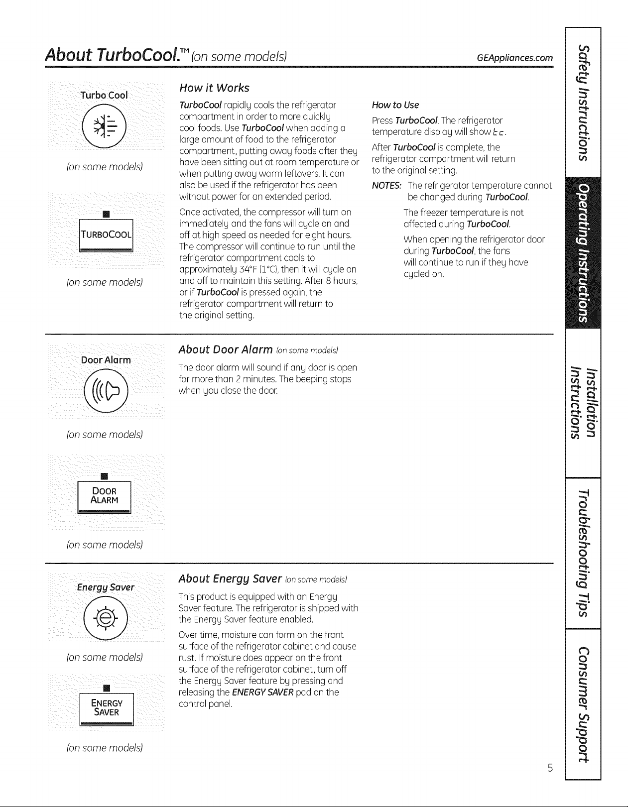
How it Works
How to Use
PressTurboCool.The refrigerator
temperature displag will showbc.
After TurboCool is complete, the
refrigerator compartment will return
to the original setting.
NOTES:The refrigerator temperature cannot
be changed during TurboCool.
Thefreezertemperature is not
affected during TurboCool.
When opening the refrigerator door
during TurboCool, the fans
will continue to run if theg have
cgcled on.
(onsome models)
iillTM _ _ i_i_ii _iii _i _ _/
ii_ _i _ _! _l_ ii_ i_ii__IIil
ITUR OCOOL
(on some models)
TurboCool rapidlg cools the refrigerator
compartment inorder to more quickly
coolfoods. UseTurboCool when adding a
large amount of food to the refrigerator
compartment, putting away foods after they
have been sitting out at room temperature or
when putting away warm leftovers. It can
alsobe usedif the refrigerator hasbeen
without power for an extended period.
Onceactivated, the compressor will turn on
immediatel9 andthe fans will cycle on and
off at highspeed as neededfor eight hours.
The compressor will continue to run until the
refrigerator compartment coolsto
approximatelg 34°F(I°C),then it will cgcle on
and off to maintain this setting.After 8hours,
or if TurboCool ispressedagain, the
refrigerator compartment will return to
the original setting.
DoorAlarm
(on some models)
[]
ALARMDOOR
(on some models)
(on some models)
i I i TM /_[]
ENERGY
SAVER
About Door Alarm (onsome models)
Thedoor alarm will sound if ang door is open
for more than 2 minutes.The beeping stops
when gouclosethe door.
About Energg Saver (onsome models)
Thisproduct is equipped with an Energg
Saverfeature.Therefrigerator isshippedwith
the EnerggSaverfeature enabled.
Overtime, moisture can form on the front
surface of the refrigerator cabinet and cause
rust. Ifmoisture does appear onthe front
surface of the refrigerator cabinet, turn off
the EnerggSaverfeature bg pressing and
releasingthe ENERGY'SAVERpad on the
control panel.
(on some models)
About the water filter. (onsome models)
i i I _,ii ii iii
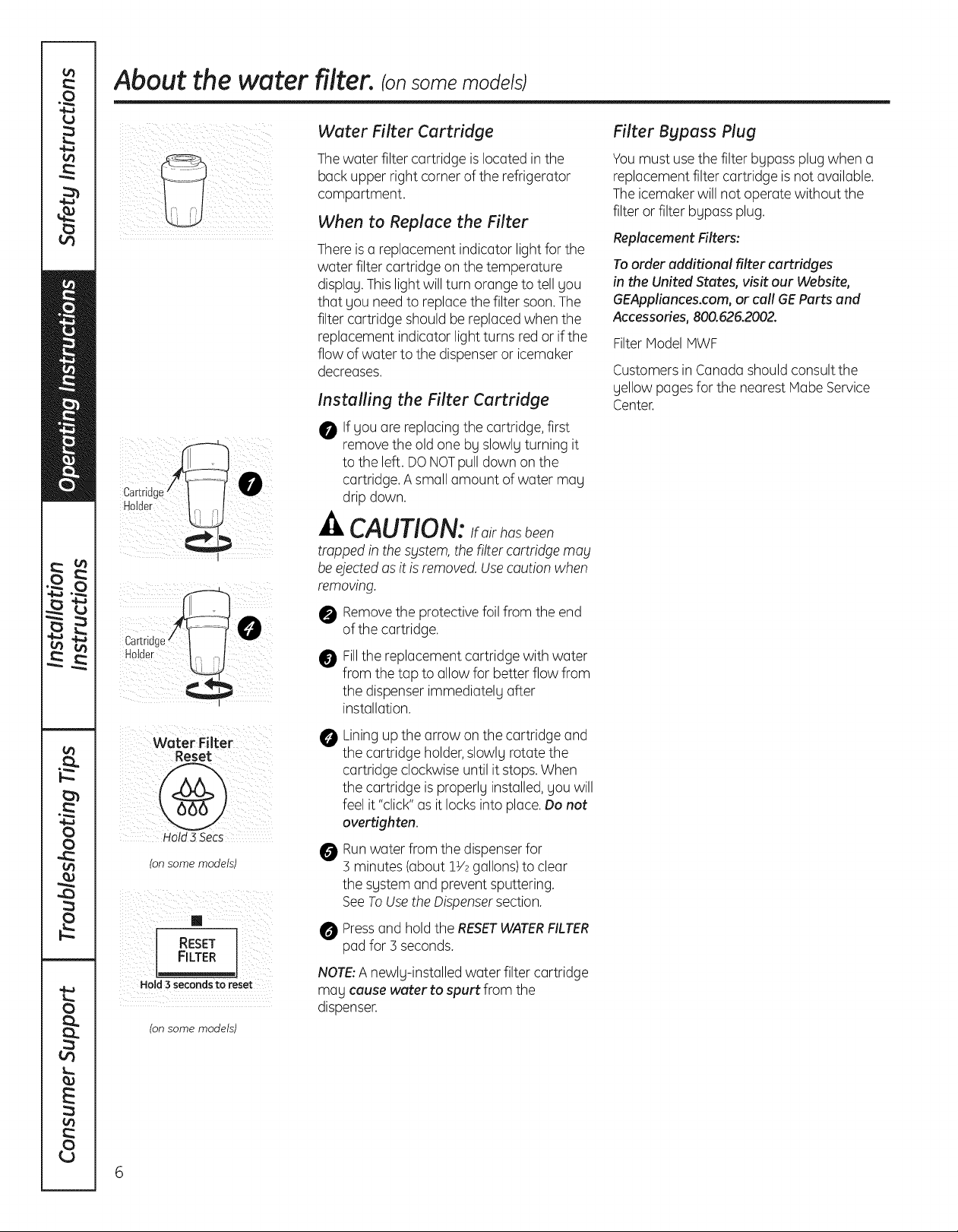
Water Filter Cartridge
Thewater filtercartridge islocated in the
back upper right corner of the refrigerator
compartment.
When to Replace the Filter
There isa replacement indicator light for the
water filter cartridge on the temperature
displag.Thislight will turn orange to tell gou
that gou needto replacethe filter soon.The
filter cartridge should be replaced when the
replacement indicator light turns redor if the
flow of water to the dispenseror icemaker
decreases.
Installing the Filter Cartridge
O If gou are replacingthe cartridge, first
remove the old one bgslowlg turning it
to the left. DONOTpull down on the
cartridge. A small amount of water mag
drip down.
-& CAUTION:Ifairhasbeen
trapped in the sblstem,thefilter cartridgemay
be ejectedasit isremoved.Usecaution when
removing.
Removethe protective foilfrom the end
of the cartridge.
Filter Bypass Plug
Youmust usethe filter bgpass plug when a
replacement filter cartridge isnot available.
The icemakerwill notoperate without the
filter or filter bgpass plug.
Replacement Filters:
To order additional filter cartridges
in the United States, visit our Website,
GEAppliances.com, or call GEParts and
Accessories, 800.626.2002.
Filter Model MWF
CustomersinCanada should consult the
gellow pagesfor the nearest MabeService
Center.
Water Filter
Reset
Hold 3 Secs
(on some models)
RESET
FILTER
Hold 3 seconds to reset
(on some models)
Fillthe replacement cartridge with water
from the tap to allow for better flow from
the dispenser immediatelg after
installation.
Liningup the arrow onthe cartridge and
O
the cartridge holder,slowlg rotatethe
cartridge clockwiseuntil itstops.When
the cartridge isproperlg installed,gou will
feel it "click"as it locks into place.Do not
overtighten.
Runwater from the dispenserfor
O
3 minutes (about 1V2gallons)to clear
the sgstem and prevent sputtering.
SeeToUsethe Dispensersection.
Pressand hold the RESETWATERFILTER
pad for 3seconds.
NOTE:A newlg-installed water filter cartridge
mag cause water to spurt from the
dispenser.
6
About the shelves and bins. GEAppliances.com
Not all features are on all models.
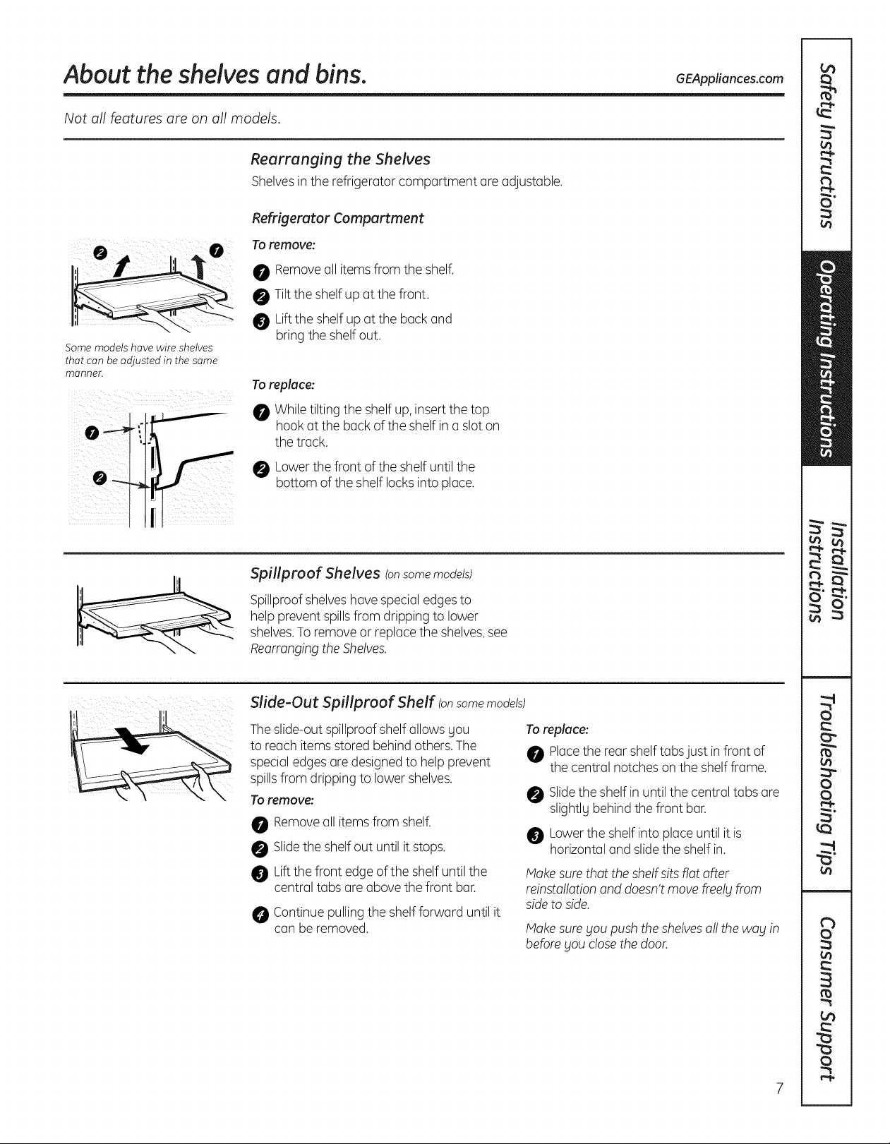
Rearranging the Shelves
Shelves in the refrigerator compartment are adjustable.
Refrigerator Compartment
Toremove:
0 Removeall itemsfrom the shelf.
0 Tilt the shelf up at the front.
Liftthe shelf up at the back and
Some models have wire shelves
that can be adjusted in the same
manner.
bring the shelf out.
To replace:
While tilting the shelf up, insert the top
hook at the back of the shelf ina slot on
the track.
Lowerthe front of the shelf until the
bottom ofthe shelf locksinto place.
Spillproof Shelves (onsome models)
Spillproofshelveshavespecial edgesto
help prevent spillsfrom dripping to lower
shelves.Toremoveor replacethe shelves,see
RearrangingtheShelves.
Slide-Out Spillproaf Shelf (on some models)
Theslide-outspillproof shelfallows gou
to reach itemsstored behindothers.The
special edgesaredesigned to help prevent
spillsfrom dripping to lower shelves.
Toremove:
Removeall itemsfrom shelf.
Slidethe shelf out until it stops.
Liftthe front edge of the shelf until the
central tabs areabove the front bar.
Continue pulling the shelf forward until it
can be removed.
To replace:
Place the rear shelf tabs just in front of
the central notches on the shelf frame.
Slidethe shelf in until the central tabs are
slightlg behind the front bar.
Lower the shelf into place until it is
horizontal and slide the shelf in.
Make sure that the shelf sits fiat offer
reinsta!lation and doesn't move free!g from
side to side.
Makesuregou push theshelvesa!!the wag in
beforegouclosethe door.
About the shelvesand bins.
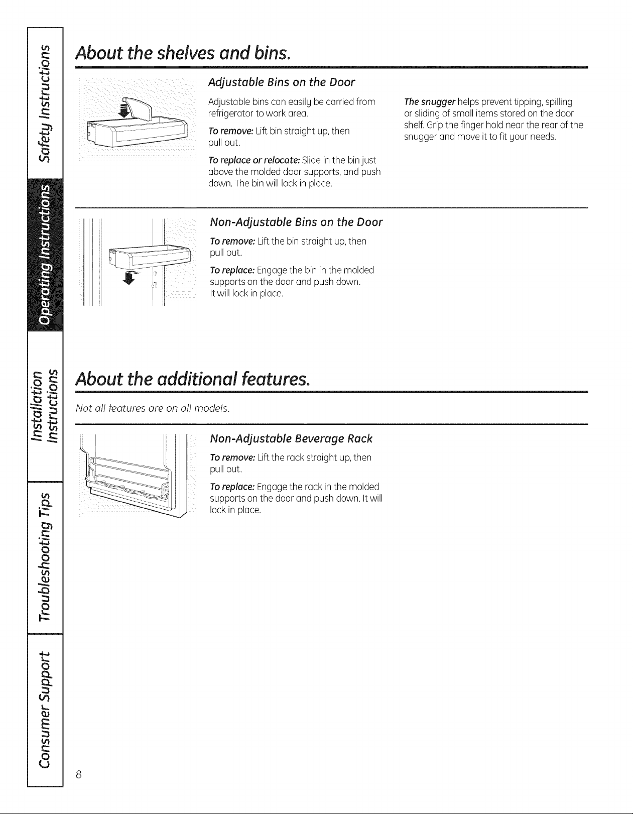
Adjustable Bins on the Door
Adjustable bins can easilgbecarried from
refrigerator to work area.
Toremove: Liftbin straight up,then
pull out.
Toreplace or relocate: Slide inthe binjust
above the molded door supports, and push
down. The binwill lock in place.
Non-Adjustable Bins on the Door
Toremove: Lift the bin straight up,then
pull out.
Toreplace: Engagethe bin inthe molded
supports on the doorand push down.
It will lock in ploce.
About the additional features.
Thesnugger helpsprevent tipping, spilling
or sliding of small itemsstored on the door
shelf.Gripthe finger hold near the rearof the
snugger and move itto fit gour needs.
Not oll feotures ore on oll models.
Non-Adjustable Beverage Rack
Toremove: Lift the rack straight up,then
pull out.
Toreplace: Engagethe rack inthe molded
supports on the doorand push down. Itwill
lock in place.
8
About the crispers and pans. GEAppliances.cam
Not all features are on all models.
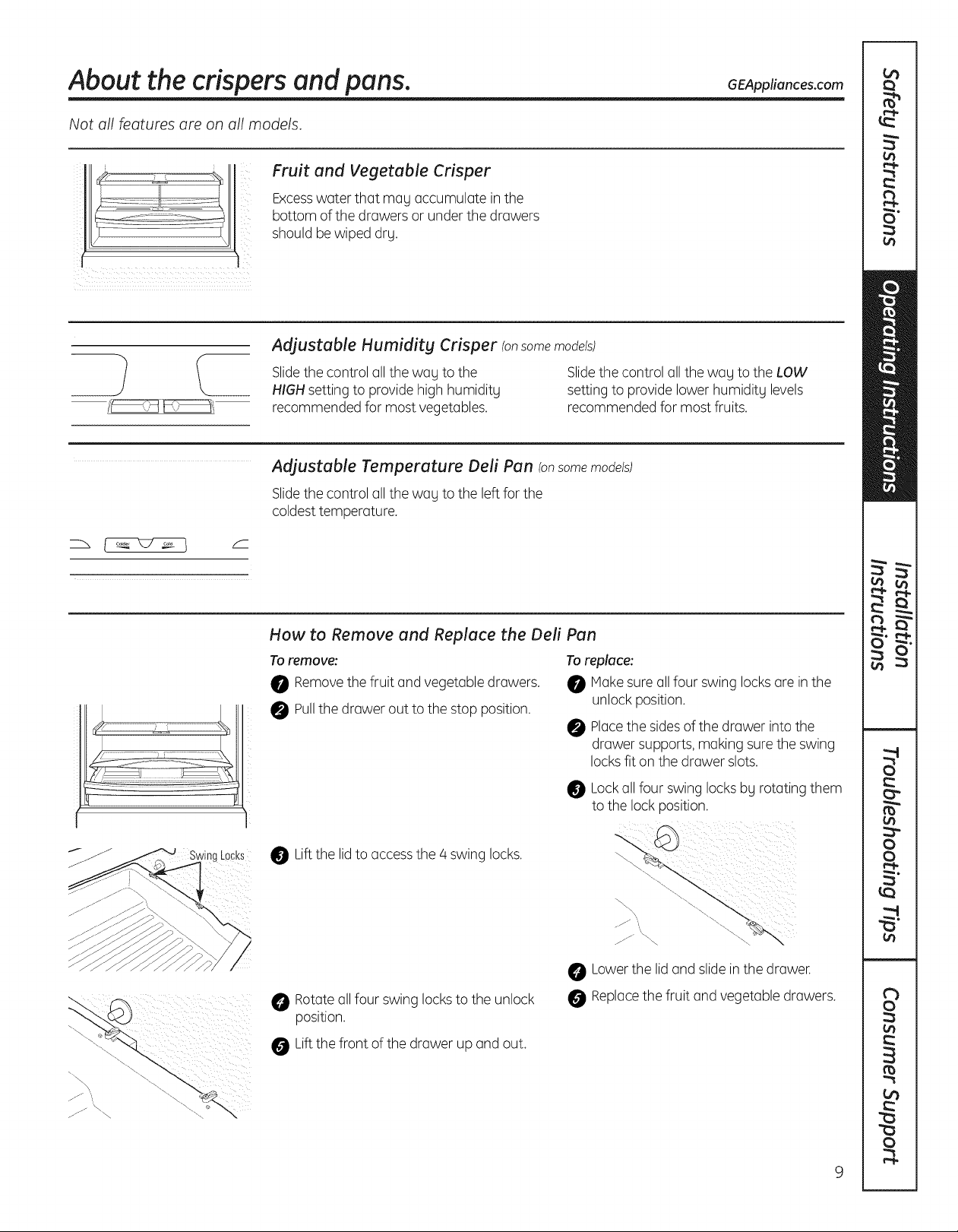
Fruit and Vegetable Crisper
Excesswater that may accumulate in the
bottom of the drawers or under the drawers
should be wiped dry.
Adjustable Humidity Crisper (onsomemodels)
Slidethe control all the way to the
HIGHsetting to provide high humidity
recommended for most vegetables.
Adjustable Temperature Dell Pan (onsome models)
Slidethe control all the way to the left for the
coldesttemperature.
Slidethe control all the wag to the LOW
setting to providelower humidity levels
recommended for most fruits.
How to Remove and Replace the Dell Pan
To remove:
0 Removethe fruit and vegetable drawers.
0 Pullthe drawer out to the stop position.
Liftthe lidto accessthe 4 swing locks.
Rotateallfour swinglocksto the unlock
position.
Liftthe front of the drawer up and out.
To replace:
0 Replacethe fruit and vegetable drawers.
Makesure allfour swing locksare inthe
unlock position.
Placethe sidesof the drawer intothe
drawer supports,making surethe swing
locksfit on the drawer slots.
Lockall four swing locksby rotating them
to the lockposition.
Lowerthe lid and slide inthe drawer.
About the freezer.
Not all features are on all models.
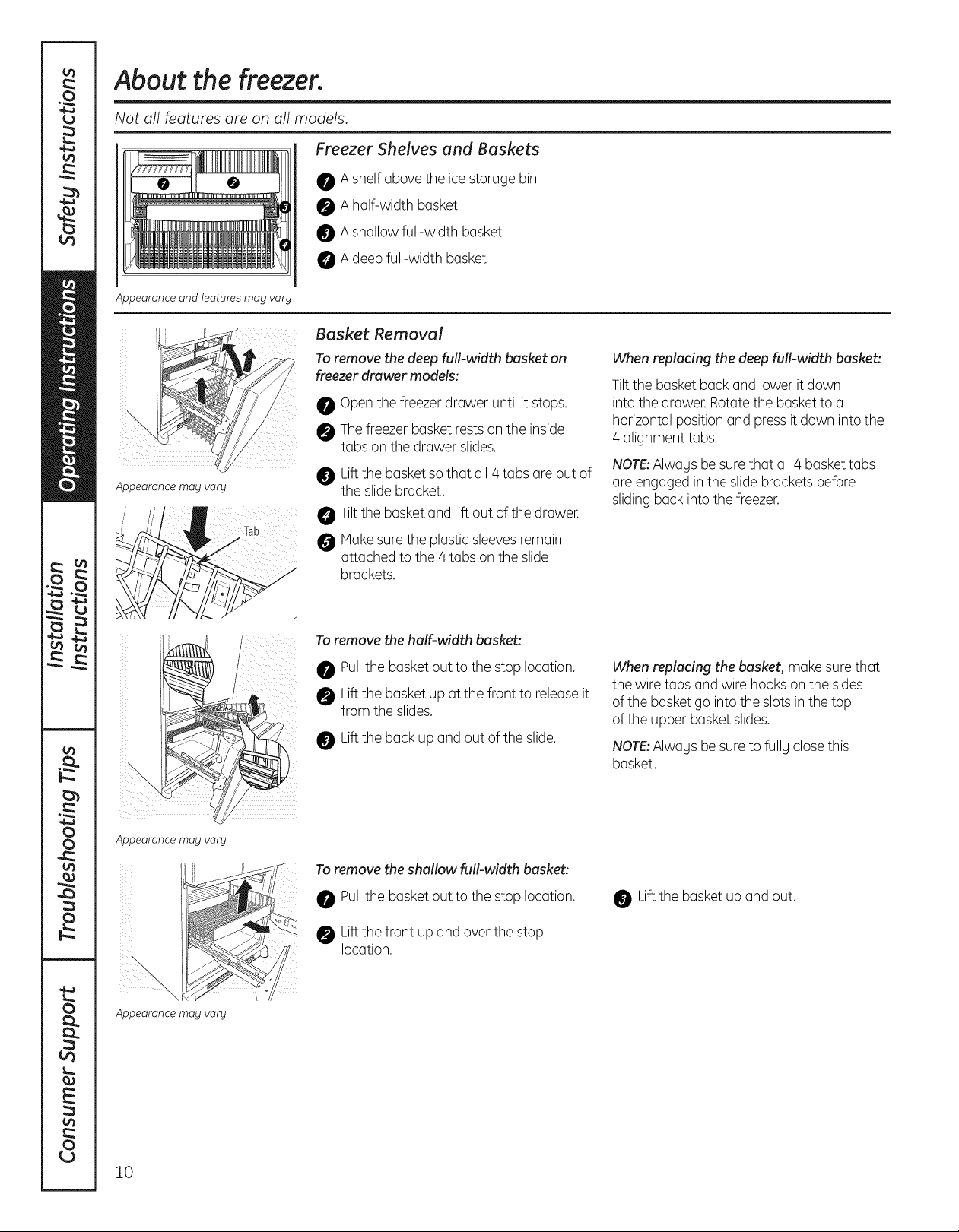
Freezer Shelves and Baskets
0 A shelf above the ice storage bin
0 A half-width basket
Appearance and features may vary
Basket Removal
To remove the deep full-width basket on
freezer drawer models:
Appearance mag varg
A shallow full-width basket
A deep full-width basket
Open the freezer drawer until it stops.
Thefreezerbasket rests on the inside
tabs on the drawer slides.
Liftthe basket so that all 4 tabs are out of
the slide bracket.
Tilt the basket and lift out of the drawer.
Makesure the plastic sleevesremain
attached to the 4 tabs onthe slide
brackets.
When replacing the deep full-width basket:
Tiltthe basket back and lower it down
into the drawer. Rotatethe basketto a
horizontal position and pressit down intothe
4 alignment tabs.
NOTE:Alwagsbesure that all4 baskettabs
are engaged in the slidebrackets before
sliding back into the freezer.
Appearance may vary
Appearance may vary
To remove the half-width basket:
Pullthe basket out to the stop location.
Liftthe basket up at the front to releaseit
from the slides.
Liftthe back up and out of the slide.
To remove the shallow full-width basket:
Pullthe basket out to the stop location.
Liftthe front up and over the stop
location.
When replacing the basket, make surethat
the wire tabs and wire hooks on the sides
of the basket go into the slots in the top
of the upper basket slides.
NOTE:Alwagsbesure to fullg closethis
basket.
Liftthe basket up and out.
10
About the automatic icemaker. GEAppliances.com
A newly installed refrigerator may take J2 to 2/4hours to begin making ice.
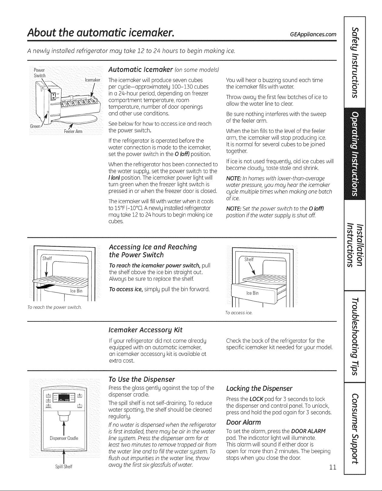
Automatic Icemaker (onsome models)
The icemakerwill producesevencubes
per cycle-approximately 100-1]0 cubes
in a 24-hour period, depending onfreezer
compartment temperature, room
temperature, number of door openings
and other use conditions.
Seebelow for how to access iceand reach
the power switch.
If the refrigerator isoperated before the
water connection ismade to the icemaker,
setthe power switch in the 0 (offJposition.
Whenthe refrigerator has been connected to
the water supply, set the power switch to the
I(on)position.The icemaker power lightwill
turn green when the freezer light switch is
pressedin orwhen the freezer door is closed.
Theicemakerwillfillwith water when it cools
to 15°F(-10°C).Anewly installedrefrigerator
may take 12to 2/4hoursto begin making ice
cubes.
Accessing Ice and Reaching
the Power Switch
Youwill hear a buzzingsound each time
the icemaker fillswith water.
Throw away the first few batches of ice to
allow the water lineto clear.
Besure nothing interfereswith the sweep
of the feeler arm.
When the bin fills to the levelofthe feeler
arm, the icemakerwill stop producing ice.
It is normal for several cubes to bejoined
together.
If ice isnot used frequently, old ice cubes will
become cloudy, taste staleand shrink.
NOTE:Inhomes with lower-than-average
water pressure,_joumay hearthe icemaker
qjcle multiple timeswhen makingonebatch
of ice.
NOTE:Set the power switch to the 0 (off)
position if the water supply is shut off.
To reach the power switch.
Y
DispenserCradle
SpillShelf
ii__ i
To reach the icemaker power switch, pull
the shelf above the ice bin straight out.
Always be sureto replacethe shelf.
To access ice, simply pull the bin forward.
Icemaker Accessory Kit
If your refrigerator did not come already
equipped with an automatic icemaker,
an icemaker accessory kitisavailable at
extra cost.
To Use the Dispenser
Pressthe glass gently against the top of the
dispensercradle.
Thespill shelf is not self-draining.Toreduce
water spotting, the shelfshould be cleaned
regularly.
If no water isdispensedwhen therefrigerator
isfirst installed,there may be air in thewater
linesystem. Pressthe dispenserarm for at
leasttwo minutes to removetrapped air from
thewater lineand to fill the water system. To
flush out impurities in the water line,throw
away thefirst six glassfulsof water.
Toaccessice.
Checkthe back of the refrigerator for the
specific icemaker kit neededfor your model.
Locking the Dispenser
Pressthe LOCKpad for ] secondsto lock
the dispenser and control panel.To unlock,
pressand holdthe pad againfor ] seconds.
Door Alarm
Tosetthe alarm,pressthe DOORALARM
pad.Theindicator light will illuminate.
This alarm will sound ifeither door is
open for more than 2 minutes. The beeping
stopswhen you closethe door.
11
Careand cleaning of the refrigerator.
Cleaning the Outside
Thedoor handles and trim. Cleanwith a
cloth dampened with soapy water. Dry with
a soft cloth. Do not usewax on the door
handlesand trim.
Keepthe outside clean. Wipe with aclean
cloth lightly dampened with kitchen
appliance wax or mild liquid dish detergent.
Dry and polishwith a clean,soft cloth.
Do not wipe the refrigerator with a soiled
dish cloth or wet towe!. These may leave a
residue that can erode the paint. Do not
use scouring pads, powdered cleaners,
bleach or cleaners containing bleach
because these products can scratch and
weaken the paint finish.
Cleaning the Inside
Tohelpprevent odors, leave an open box of
baking soda in the refrigerator and freezer
compartments.
Unplug the refrigerator before cleaning. If
this is not practical, wring excessmoisture
out of sponge or clothwhen cleaning around
switches,lights orcontrols.
Usean appliance wax polish on the inside
surface between the doors.
Usewarm water and baking soda solution-
about a tablespoon (15ml)of baking soda to
a quart (1liter)of water.This both cleansand
neutralizesodors. Rinseand wipe dry.
Thestainless steel panels and door
handles.
Stainlesssteel (onsome models)can be
cleaned with a commercially available
stainlesssteel cleaner.A spray-on stainless
steel cleanerworks best.
Do not useappliance wax or polish on the
stainlesssteel.
Silver-plated plastic parts. Wash parts with
soap or other mild detergents. Wipe clean
with a sponge,damp cloth or paper towel.
Do not scrub with steel-wool pads or other
abrasive cleaners.
After cleaning the door gaskets, apply a thin
layer of petroleumjelly to the door gaskets at
the hinge side.This helpskeepthe gaskets
from sticking and bending out of shape.
Avoid cleaning cold glass shelves with hot
water because the extreme temperature
difference may cause them to break.
Handle glass shelves carefully. Bumping
tempered glass can cause it to shatter.
Do not wash any plastic refrigerator parts
in the dishwasher.
Silver-accented plastic parts. Wash parts
with soapy water.Wipe clean with a sponge,
damp clothor paper towel.
12
Do not scrub with steel-wool pads or other
abrasive cleaners.
Behind the Refrigerator
Becareful when moving the refrigerator
awag from the wall.All tgpes of floor
coveringscan be damaged, particularlg
cushioned coverings and those with
embossedsurfaces.
Raisethe levelinglegs located at the bottom
front of the refrigerator.
Pullthe refrigerator straight out and return it
to position bg pushing it straight in. Moving
the refrigerator in a side direction mag result
in damage to the floor covering or
refrigerator.
Preparing for Vacation
Forlongvacations or absences,remove food
and unplug the refrigerator.Cleanthe interior
with a baking soda solution of one
tablespoon (15ml)of baking soda to one
quart (1liter)ofwater. Leavethe doors open.
Setthe icemaker power switch to the 0 (off]
position and shut offthe water supplg to
the refrigerator.
GEAppliances.com
Lowerthe leveling legs untiltheg touch
the floor.
When pushing the refrigerator back, make
sure gou don't rol! over the power cord or
icemaker supplg line (onsome models) and
ensure the anti-tip bracket is engaged (if
equipped).
If the temperature can drop below freezing,
have a qualified servicer drain the water
supplg sgstem (on some models)to prevent
serious propertg damage dueto flooding.
Preparing to Move
Secureall looseitems such as base grille,
shelvesand drawers bg taping them
securelg in placeto prevent damage.
When using a hand truck to movethe
refrigerator,donot restthe front or back
of the refrigerator against the hand truck.
This could damage the refrigerator.Handle
onlg from the sidesof the refrigerator.
Be sure the refrigerator stags in an upright
position during moving.
13
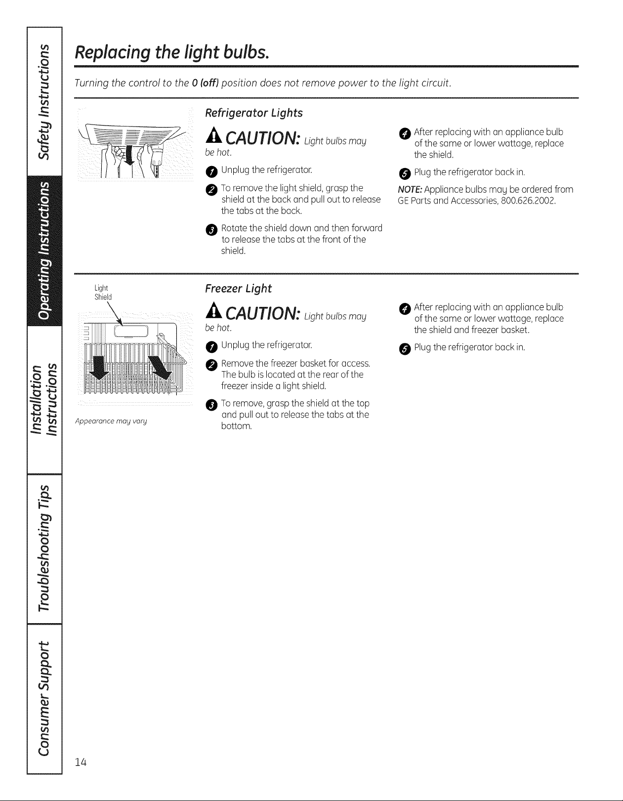
Replacing the light bulbs.
Turning the control to the 0 (off) position does not remove power to the light circuit.
Refrigerator Lights
Light
Shield
Appearance may vary
_, CAUTION:Lightbu/b_mou
be hot.
0 Unplugthe refrigerator.
Toremovethe light shield,grasp the
shieldatthe back and pulloutto release
the tabsat the back.
Rotatethe shielddown and then forward
to releasethe tabs at the front of the
shield.
Freezer Light
_' CAUTION: Lightbu/b_may
be hot.
Unplugthe refrigerator.
Removethe freezer basket for access.
The bulb is located at the rear of the
freezer insidea light shield.
O To remove, graspthe shieldat the top
and pull out to releasethe tabs at the
bottom.
After replacing with an appliance bulb
of the same or lowerwattage, replace
the shield.
Plugthe refrigerator back in.
NOTE:Appliance bulbsmag beorderedfrom
GEPartsand Accessories,800.626.2002.
After replacing with an appliance bulb
of the same or lowerwattage, replace
the shieldand freezer basket.
Plugthe refrigerator back in.
14
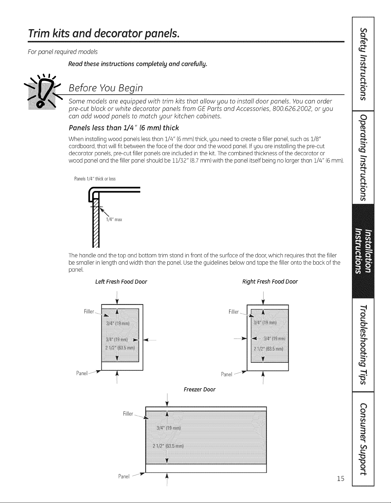
Trim kits and decorator panels.
For panel required models
Read these instructions completely and carefully.
Before You Begin
Some models are equipped with trim kits that allow you to install door panels. You can order
pre-cut black or white decorator panels from GE Parts and Accessories, 800.626.2002, or you
can add wood panels to match your kitchen cabinets.
Panels less than 1/4" (6 mm) thick
When installingwood panels lessthan 1/4" (6mm) thick, you need to create a filler panel,such as 1/8"
cardboard, that will fit between the face of the door and the wood panel. Ifyou are installing the pre-cut
decorator panels, pre-cut filler panels are included in the kit.Thecombined thickness of the decorator or
wood panel and the filler panel should be 11/]2" (8.7mm)with the panel itselfbeing nolarger than 1/4" (6mm).
Panels1/4"thickorless
1/4" max
Thehandle and the top and bottom trim stand infront of the surface of the door,which requiresthat the filler
be smaller in length and width than the panel.Usethe guidelinesbelow and tape the filler onto the back of the
panel.
Panel
Left Fresh Food Door
Filler_
Panel
Freezer Door
Right Fresh Food Door
Filler_
Filler-
Panel
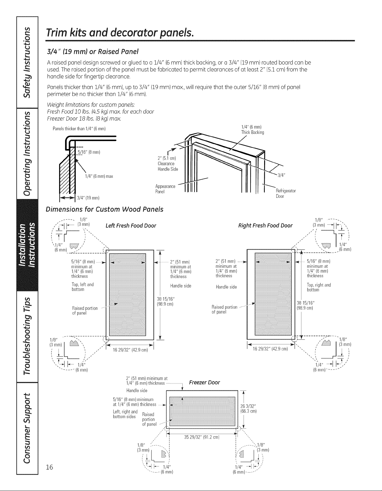
Trim kits and decorator panels.
3/4" (19 mm) or Raised Panel
A raised panel design screwed or glued to a 1/4" (6mm) thick backing,or a3/4" (19mm)routed boardcan be
used.The raised portion of the panel must be fabricated to permit clearances of at least 2" (5.1 cm)from the
handle sidefor fingertip clearance.
Panelsthicker than 1/4" (6mm),up to 5/4" (19mm)max.,will require that the outer 5/16" (8mm) of panel
perimeter be no thicker than 1/4" (6mm).
Weight limitations for custom panels:
FreshFood!0 Ibs.(4.5kg)max. for eachdoor
FreezerODor!8 Ibs. (8kg)max.
Panelsthickerthan1/4" (6ram)
1/4" (6mm)
ThickBacking
5/16" (8mm)
1/4" (6mm)max
3/4"(19 mm)
Dimensions for Custom Wood Panels
. ..... 1/8"
,,"'_ i_ (3,:_-n) Left Fresh Food Door
',:
",1/4" ,/ .
(6mm).... _'i'_.........
5/16" (8 mm)
minimumat
1/4" (6 mm)
thickness
Top,left and
bottom
Raisedportion
of panel
:::::::::::::::::::::::::::::::::::::::::::::::::::::::::::::::::::::::::::.
:::::::::::::::::::::::::::::::::::::::::::::::::::::::::::::::::::::::::::::.
d"
2" (5.1cm)
Clearance
HandleSide
Appearance
Panel
2" (51mm)
minimumat
1/4" (6 mm)
thickness
Handleside
3815/16"
(98.9cm)
2" (51mm) _,_
mlmmumat |
1/4"(6 mm) |
thickness /
Handleside
Raisedportion
of panel
Refrigerator
Door
1/8...... -.
Right Fresh Food Door (S,mm) _l i_L", '
_ ', / 1/4"
(',-- "'. .(6 ram)
l
/
_, 5/1G,'8mm
minimumat
1/4" (6mm)
thickness
Top,right and
bottom
16
1629/32" (42.9cm)
2" (51 ram)minimumat
1/8" -...... I
"'.t_q I_ l/z_"
..... (6 mm)
3529/32" (91.2cm)
I_ 16 29/32" (42.9cm)
I+-i___ "_,\
l,- ..... _:_1/8"
,
1'/4" _ F!,'"
(6mm).......
stalJati
I
Refri erator
I
str
Questions? call 800.GE.CARES (800.432.2737) or visit our Website at: GEAppliances.com
In Canada, call 1.800.561.3344 or visit our Website at: www.GEAppliances.ca
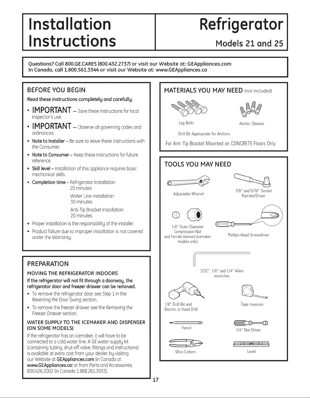
BEFORE YOU BEGIN
Read these instructions completely and carefully.
cti
Models 21 and 25
MATERIALS YOU MAY NEED (notincluded)
•IMPORTANT-sovetheseinstructionsforlocol
inspector's use.
LagBolts
• IMPORTANT- Observeoilgoverning codesand
ordinances.
• Note to Installer - Besureto leavethese instructions with
the Consumer.
• Note to Consumer- Keepthese instructions for future
reference.
• Skill level- Installationof this appliance requiresbasic
mechanical skills.
• Completion time- RefrigeratorInstallation
20 minutes
Water Line Installation
30 minutes
DrillBit AppropriateforAnchors
ForAnti-Tip BracketMounted onCONCRETEFloorsOnly
TOOLS YOU MAC NEED
AdjustableWrench
AnchorSleeves
3/8" and5/16" Socket
Ratchet/Driver
Anti-Tip BracketInstallation
20 minutes
• Properinstallationis the responsibilityof the installer.
• Productfailure dueto improper installation isnot covered
under the Warranty.
PREPARATION
MOVING THE REFRIGERATOR INDOORS
If the refrigerator will not fit through a doorway, the
refrigerator door and freezer drawer can be removed.
• Toremovethe refrigerator door,seeStep 1 in the
Reversingthe DoorSwingsection.
• Toremovethe freezerdrawer,see the Removingthe
FreezerDrawer section.
WATER SUPPLYTO THE ICEMAKER AND DISPENSER
(ON SOME MODELS)
If the refrigerator has on icemoker,it will hoveto be
connected to o coldwater line.AGEwater supply kit
(containing tubing, shut-off valve,fittings and instructions)
isavailable at extra cost from your dealer,by visiting
our Website at GEAppliances.com(inCanada at
www.GEAppliances.ca)or from PortsandAccessories,
800.626.2002(InCanada 1.888.261.305£
1/4" OuterDiameter
CompressionNut
andFerrule(sleeve)(icemaker
modelsonly)
3/32", 1/8" and1/4" Allen
1/8" Drill Bit and
ElectricorHandDrill
Pencil
WireCutters
Phillips-HeadScrewdriver
wrenches
Tapemeasure
1/4" Nut Driver
Level
17
Installation Instructions
INSTALLING THE ANTI-TIP FLOOR BRACKET Ion21ft. models}
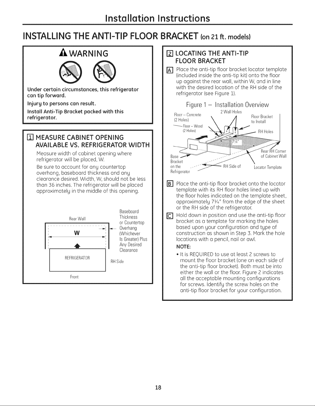
-ZIWARNING
Under certain circumstances, this refrigerator
can tip forward.
Injury to persons can result.
Install Anti-Tip Bracket packed with this
refrigerator.
m MEASURE CABINET OPENING
AVAILABLE VS. REFRIGERATOR WIDTH
Measure width of cabinet opening where
refrigerator will be placed, W.
Be sure to account for anLI countertop
overhang, baseboard thickness and anLI
clearance desired. Width, W, should not be less
than 36 inches. The refrigerator will be placed
approximatelLI in the middle of this opening.
Baseboard
RearWall
W
REFRIGERATOR
Front
Thickness
or C0untertop
Overhang
(Whichever
Is Greater)Plus
AnyDesired
Clearance
RHSide
LOCATING THE ANTI-TIP
[]
FLOOR BRACKET
Place the anti-tip floor bracket Iocator template
%
(included inside the anti-tip kit) onto the floor
up against the rear wall, within W, and in line
with the desired location of the RH side of the
refrigerator (see Figure 1).
Figure1- InstallationOverview
Floor- Concrete
Refrigerator
rB] Place the anti-tip floor bracket onto the Iocator
template with its RH floor holes lined up with
the floor holes indicated on the template sheet,
approximatelg 7Ya" from the edge of the sheet
or the RH side of the refrigerator.
_] Hold down in position and use the anti-tip floor
bracket as a template for marking the holes
based upon gour configuration and tLIpe of
construction as shown in Step 3. Mark the hole
locations with a pencil, nail or awl.
NOTE:
• It is REQUIREDto use at least 2 screws to
mount the floor bracket (one on each side of
the anti-tip floor bracket). Both must be into
either the wall or the floor. Figure 2 indicates
all the acceptable mounting configurations
for screws. Identifg the screw holes on the
anti-tip floor bracket for gour configuration.
2Wall Holes
18
Installation Instructions
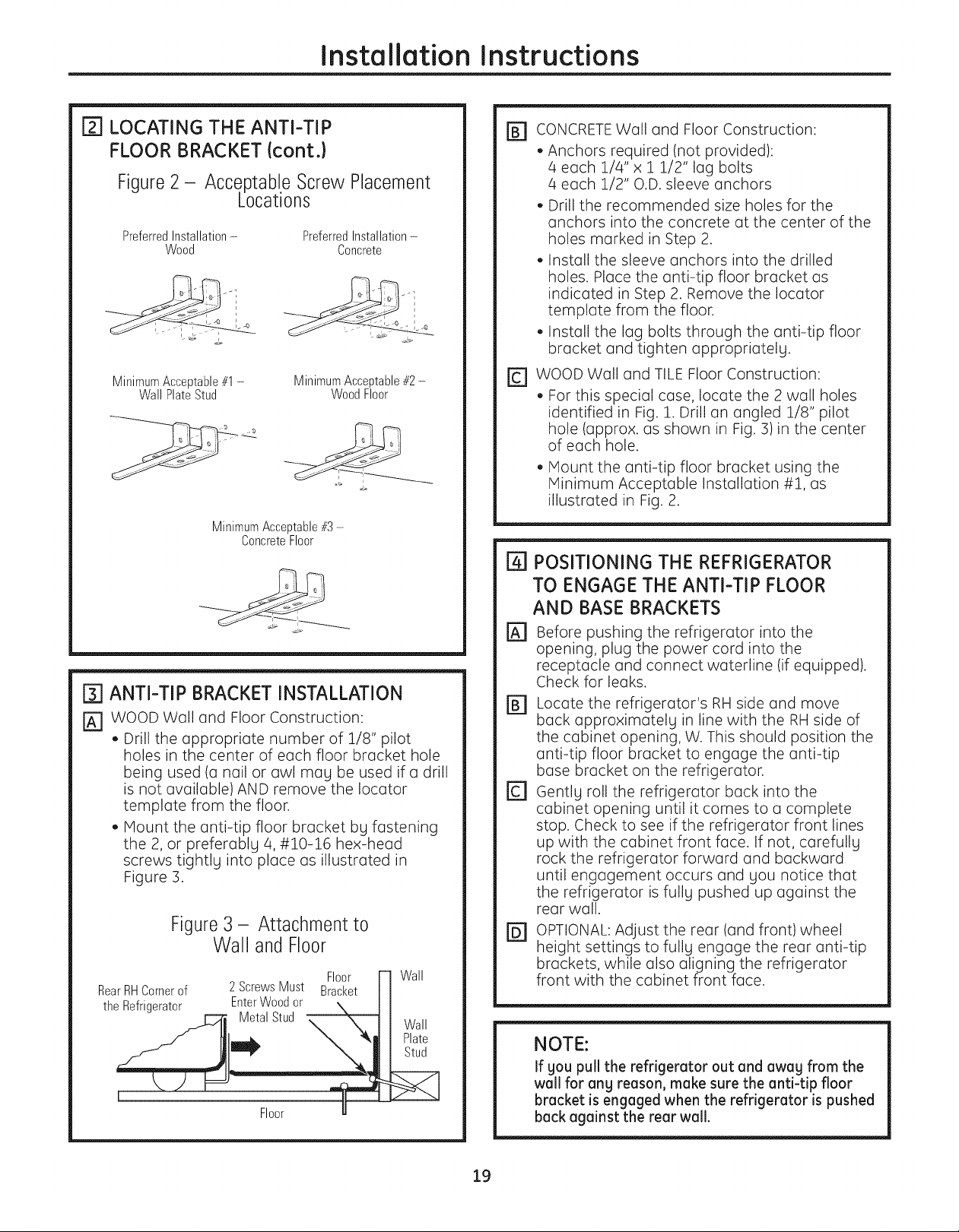
[_] LOCATING THE ANTI-TIP
FLOOR BRACKET {cont.}
Figure 2 - Acce,ptabl.eScrew Placement
Locations
PreferredInstallation- PreferredInstallation-
Wood Concrete
MinimumAcceptable#1-
Wall PlateStud
MinimumAcceptable#3 -
ConcreteFloor
MinimumAcceptable#2-
WoodFloor
[] ANTI-TIP BRACKET INSTALLATION
[] WOOD Wall and Floor Construction:
• Drill the appropriate number of 1/8" pilot
holes in the center of each floor bracket hole
being used (a nail or awl mag be used if a drill
is not available) AND remove the Iocator
template from the floor.
• Mount the anti-tip floor bracket bg fastening
the 2, or preferablg 4, #10-16 hex-head
screws tightlg into place as illustrated in
Figure 3.
Figure3- Attachmentto
Wall and Floor
RearRHCornerof
the Refrigerator
2 ScrewsMust Bracket
EnterWoodor
Metal Stud
Floor
Floor Wall
Wall
Plate
Stud
r_ CONCRETEWall and Floor Construction:
• Anchors required (not provided):
4 each 1/4"x 1 1/2" lag bolts
4 each 1/2" O.D. sleeve anchors
• Drill the recommended size holes for the
anchors into the concrete at the center of the
holes marked in Step 2.
• Install the sleeve anchors into the drilled
holes. Place the anti-tip floor bracket as
indicated in Step 2. Remove the Iocator
template from the floor.
• Install the lag bolts through the anti-tip floor
bracket and tighten appropriatelg.
rc] WOOD Wall and TILE Floor Construction:
• For this special case, locate the 2 wall holes
identified in Fig. 1. Drill an angled 1/8" pilot
hole (approx. as shown in Fig. 3)in the center
of each hole.
• Mount the anti-tip floor bracket using the
Minimum Acceptable Installation #1, as
illustrated in Fig. 2.
POSITIONING THE REFRIGERATOR
TO ENGAGE THE ANTI-TIP FLOOR
AND BASE BRACKETS
%
Before pushing the refrigerator into the
opening, plug the power cord into the
receptacle and connect waterline (if equipped).
Check for leaks.
Locate the refrigerator's RH side and move
@
back approximatelg in line with the RH side of
the cabinet opening, W. This should position the
anti-tip floor bracket to engage the anti-tip
base bracket on the refrigerator.
[]
Gentlg roll the refrigerator back into the
cabinet opening until it comes to a complete
stop. Check to see if the refrigerator front lines
up with the cabinet front face. If not, carefullg
rock the refrigerator forward and backward
until engagement occurs and you notice that
the refrigerator is fullg pushed up against the
rear wall.
OPTIONAL: Adjust the rear (and front) wheel
@
height settings to fullg engage the rear anti-tip
brackets, while also aligning the refrigerator
front with the cabinet front face.
NOTE:
If gou pull the refrigerator out and away from the
wall for ang reason, make sure the anti-tip floor
bracket is engaged when the refrigerator is pushed
back against the rear wall.
19
Installation Instructions
INSTALLING THE REFRIGERATOR
REFRIGERATOR LOCATION
• Do not installthe refrigerator where the temperature will
go below 60°F (16°C)because it will not run oftenenough
to maintain proper temperatures.
• Do not installthe refrigerator where the temperature will
go above IO0°F(37°C)because itwill not perform properlg.
• Installit on afloor strong enough to support it fullg loaded.
CLEARANCES
Allowthe following clearancesfor easeof installation,proper
air circulation and plumbing and electrical connections.
Standard Depth Counter Depth
Models Models
Sides 1/8" (3 mm) 1/8" (3 mm)
Top 1" (25mm) 1" (25mm)
Back 1" (25mm) 1/2" (13mm)
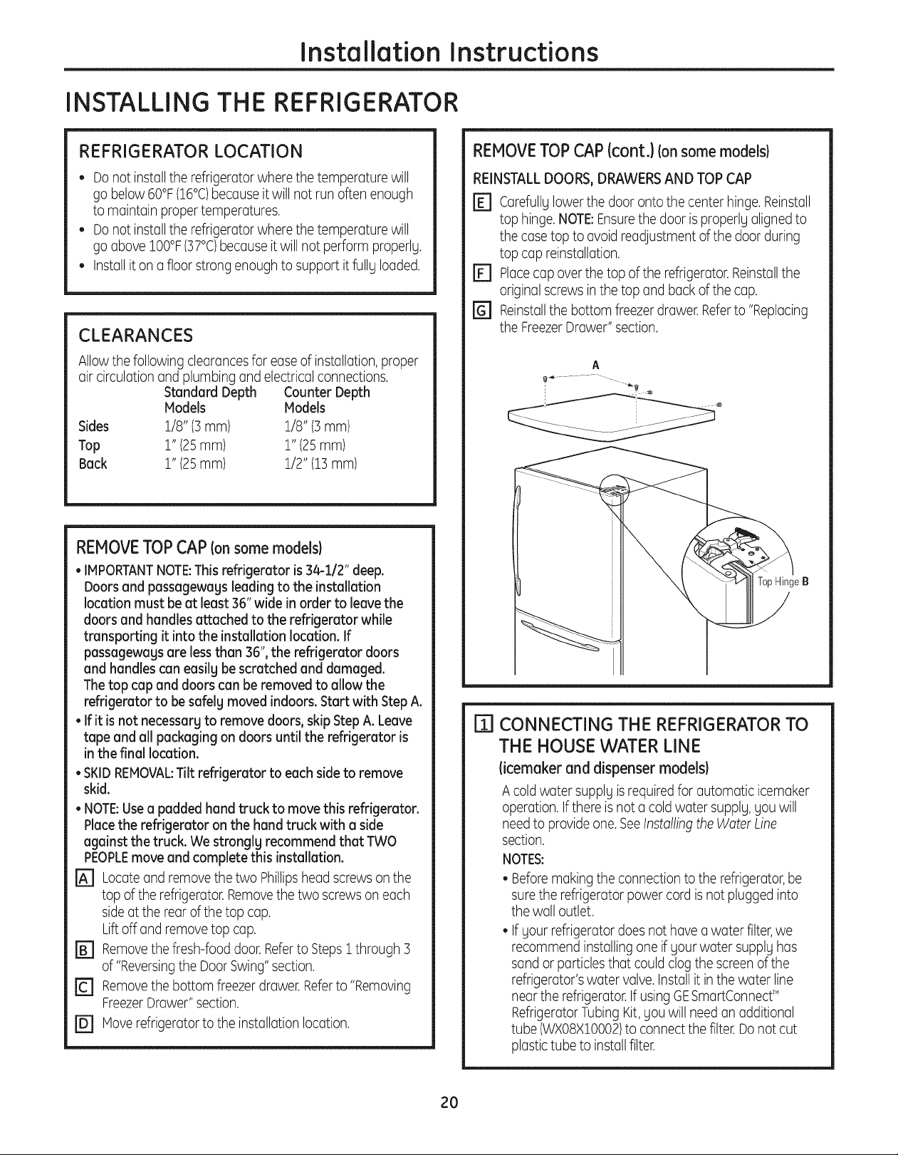
REMOVE TOP CAP (onsome models}
• IMPORTANTNOTE:This refrigerator is 34-i/2" deep.
Doors and passageways leading to the installation
location must be at least 36" wide in order to leavethe
doors and handles attached to the refrigerator while
transporting it into the installation location. If
passageways are lessthan 36", the refrigerator doors
and handles can easily bescratched and damaged.
The top cap and doors con be removed to allow the
refrigerator to be safely moved indoors. Start with Step A.
• If it is not necessary to remove doors, skip StepA. Leave
tape and all packaging on doors until the refrigerator is
in the final location.
• SKIDREMOVAL:Tilt refrigerator to each sideto remove
skid.
• NOTE:Usea padded hand truck to move this refrigerator.
Placethe refrigerator on the hand truck with a side
against the truck. We stronglg recommend that TWO
PEOPLEmove and complete this installation.
r_ Locateand remove the two Phillipshead screwson the
top ofthe refrigerator.Removethe two screws on each
sideat the rear of the top cap.
Liftoff and remove top cap.
FB] Removethe fresh-food door.Referto StepsI through ]
of "Reversingthe Door Swing"section.
r_ Removethe bottom freezerdrawer. Referto "Removing
FreezerDrawer" section.
r_ Moverefrigerator to the installation location.
REMOVE TOP CAP {cont.)Ion some models)
REINSTALLDOORS,DRAWERSAND TOP CAP
r_ carefully lowerthe door onto the center hinge.Reinstall
top hinge.NOTE:Ensurethedoor is properlg aligned to
the case top to avoid readjustment of the door during
top cap reinstallation.
r_ Placecap overthe top ofthe refrigerator.Reinstallthe
original screws inthe top and back of the cap.
r_ Reinstallthe bottom freezer drawer.Referto "Replacing
the FreezerDrawer" section.
A
TopHingeB
I]] CONNECTING THE REFRIGERATOR TO
THE HOUSE WATER LINE
(icemoker and dispenser models}
A coldwater supplg isrequired for automatic icemaker
operation. Ifthere isnot a coldwater supplg,gou will
need to provide one.SeeInstallingthe Water Line
section.
NOTES:
• Beforemakingthe connection to the refrigerator,be
surethe refrigerator power cord isnot plugged into
the wall outlet.
• If gout refrigerator does not have awater filter,we
recommend installing one if gour water supplg has
sandor particlesthat couldclog the screen of the
refrigerator'swater valve.Installit inthe water line
near the refrigerator.IfusingGESmartConnecff
RefrigeratorTubingKit,gou will needan additional
tube (WXO8XIO002)to connectthe filter.Donot cut
plastictube to installfilter.
2O
Installation Instructions
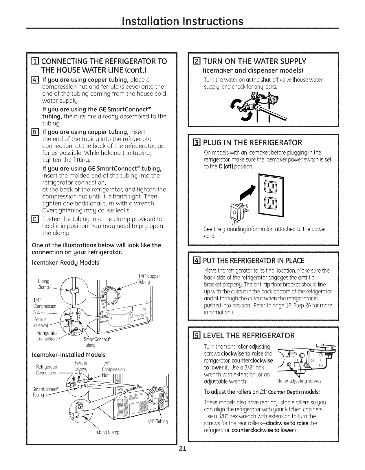
FTICONNECTING THE REFRIGERATOR TO
THE HOUSE WATER LINE (cont.}
[_ If gou are using copper tubing, place a
compression nut and ferrule (sleeve) onto the
end of the tubing coming from the house cold
water supplg.
If you are using the GE SmartConnect'"
tubing, the nuts are alreadg assembled to the
tubing.
r_ if you are using copper tubing, insert
the end of the tubing into the refrigerator
connection, at the back of the refrigerator, as
far as possible. While holding the tubing,
tighten the fitting.
If gou are using BE SmartConnect'" tubing,
insert the molded end of the tubing into the
refrigerator connection,
at the back of the refrigerator, and tighten the
compression nut until it is hand tight. Then
tighten one additional turn with a wrench.
Overtightening mag cause leaks.
r_ Fasten the tubing into the clamp provided to
hold it in position. You mag need to prg open
the clamp.
One of the illustrations below will look like the
connection on gour refrigerator.
Icemaker-Readg Models
Tubing
Clamp
1/4"
Compression
Nut
Ferrule
(sleeve)
Refrigerator
Connection
\
SmartConnecfM
Tubing
Icemaker-lnstalled Models
Refrigerator (sleeve) Compression
Connection--
SmartConnecff
Tubing
Ferrule 1/4"
TubingClamp
1/4"Copper
Tubing
1/4"Tubing
[_] TURN ON THE WATER SUPPLY
(icemaker and dispenser models)
Turnthe woter on otthe shut-off volve(housewoter
supplU)ond checkfor 0% leoks.
[] PLUG IN THE REFRIGERATOR
On modelswith on icemaker,before plugging in the
refrigerotor,mokesurethe icemokerpower switch isset
to the 0 (off} position.
Seethe grounding informotion ottoched to the power
cord.
r41 PUTTHE REFRIGERATORIN PLACE
Hove the refrigerotor to its finol Iocotion.Hoke surethe
bock sideof the refrigerotor engogesthe onti-tip
brocket properlg. Theonti-tip floor brocket should line
up with the cutout inthe bock bottom of the refrigerotor,
ond fit through the cutout when the refrigerotor is
pushed into position. (Referto poge 18,Step2Afor more
informotion.)
I'_ LEVEL THE REFRIGERATOR
Turnthe front rollerodjusting
screws clockwise to raise the
refrigerotor,counterclockwise
to lower it. UseQ]/8" hex
wrench with extension,or on
odjustoble wrench.
To adjust the milers on 21' Counter Depth models:
Thesemodelsolsohovereorodjustoblerollerssogou
conoligntherefrigerotorwithyourkitchencobinets.
Useo ]/8" hexwrench with extensionto turn the
screwsfor the reor rollers-clockwise to raise the
refrigerotor,counterclockwiseto lower it.
Rolleradjustingscrews
21
Installation Instructions
INSTALLING THE REFRIGERATOR {cont.}
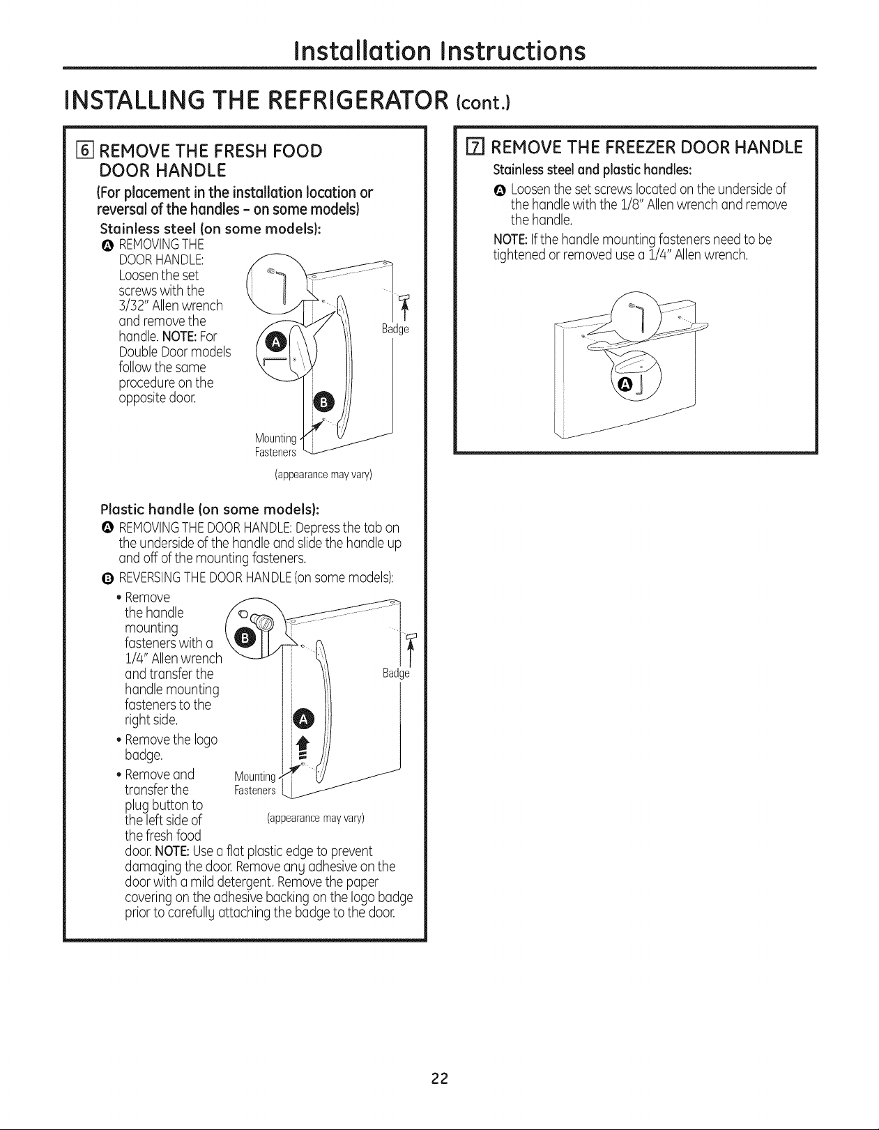
[_] REMOVE THE FRESH FOOD
DOOR HANDLE
(For placement in the installation location or
reversal of the handles - on some models}
Stainless steel (on some models}:
@ REMOVINGTHE
DOORHANDLE:
Loosenthe set
screwswith the
3/32" Allenwrench
and removethe
handle.NOTE:For
Double Door models
follow the same
procedureon the
opposite door.
Mounting
Fasteners__
(appearancemayva_)
Plastic handle Ion some models):
O REMOVINGTHEDOORHANDLE:Depressthe tab on
the underside of the handle and slidethe handle up
and off of the mounting fasteners.
0 REVERSINGTHEDOORHANDLE(onsome models):
• Remove
the handle
mounting
fasteners with a
1/4" Allenwrench
and transfer the
handle mounting
fasteners to the
right side.
• Removethe logo
badge.
• Removeand
transfer the
plug button to
the leftsideof
the fresh food
door.NOTE:Usea flat plastic edge to prevent
damaging the door.Removeang adhesiveon the
door with a mild detergent. Removethe paper
covering on the adhesive backing on the logo badge
prior to carefullg attaching the badge to the door.
Mounting-
Fasteners
(appearancemay vary)
" Badge
rT] REMOVE THE FREEZER DOOR HANDLE
Stainless steel and plastic handles:
@ Loosenthe setscrews located on the undersideof
the handle with the 1/8" Allen wrench andremove
the handle.
NOTE:Ifthe handle mounting fasteners need to be
tightened or removedusea 1/4" Allenwrench.
1
Badge
22
Installation Instructions
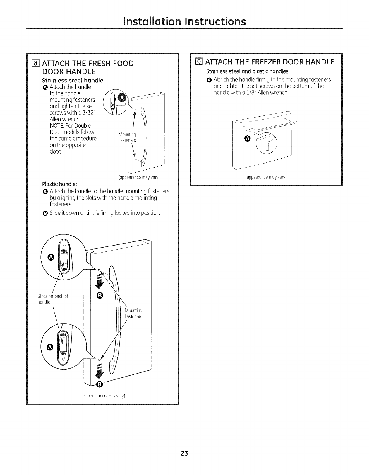
[_] ATTACH THE FRESH FOOD
DOOR HANDLE
Stainless steel handle:
@ Attachthehandle
tothehandle
mountingfasteners
andtightentheset
screwswith a 3/32"
Allenwrench.
NOTE:ForDouble
Door modelsfollow
the same procedure
on the opposite
door.
Plastic handle:
@ Attach the handle to the handle mounting fasteners
by aligning the slots with the handle mounting
fasteners.
Q Slideitdown until it isfirmly lockedinto position.
Mounting
Fasteners
(appearancemayvary)
F_ ATTACH THE FREEZER DOOR HANDLE
Stainless steel and plastic handles:
@ Attach the handle firmly to the mounting fasteners
and tighten the set screws on the bottom of the
handle with a 1/8" Allenwrench.
_J
(appearancemay vary)
Slotsonbackof U
handle
(appearancemayvary)
A
23
Installation Instructions
INSTALLING THE REFRIGERATOR {cont.}
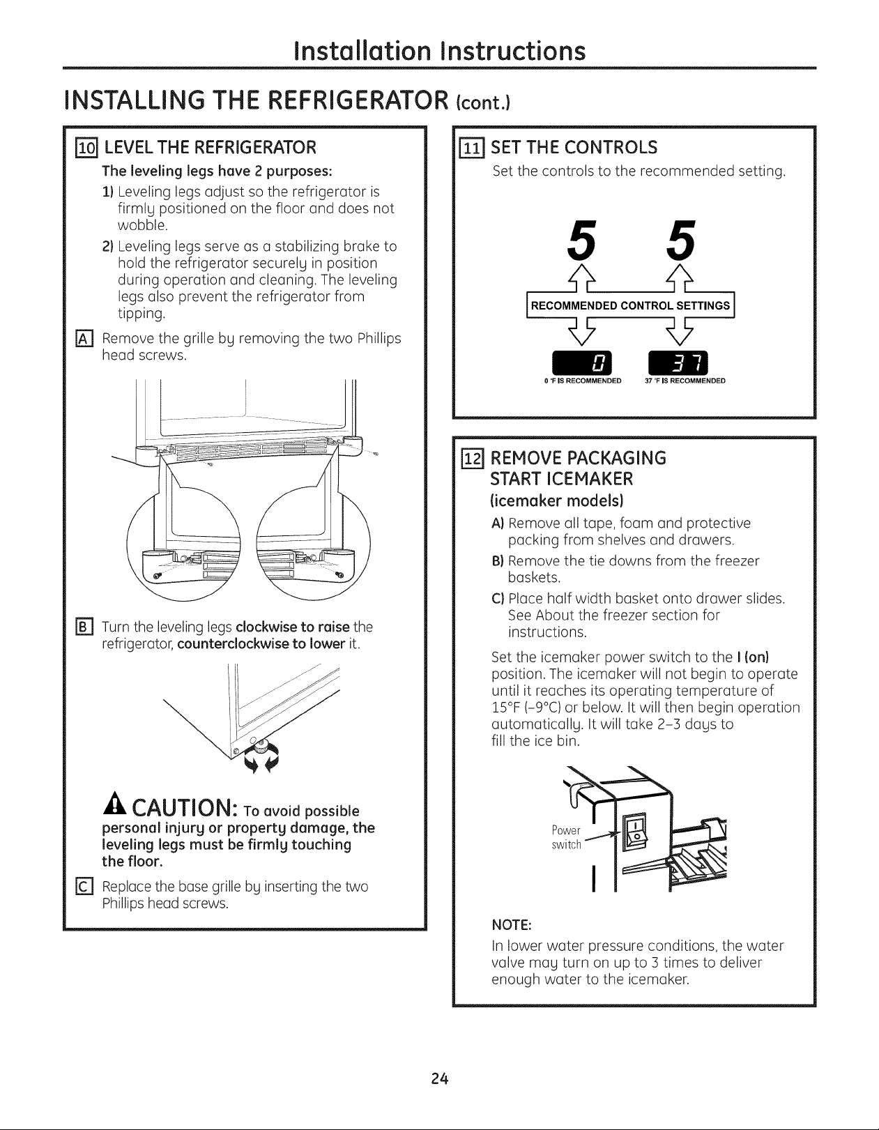
LEVEL THE REFRIGERATOR
The leveling legs have 2 purposes:
1) Leveling legs adjust so the refrigerator is
firmlg positioned on the floor and does not
wobble.
21 Leveling legs serve as a stabilizing brake to
hold the refrigerator securelg in position
during operation and cleaning. The leveling
legs also prevent the refrigerator from
tipping.
[_ Remove the grille bg removing the two Phillips
head screws.
r_ Turn the leveling legs clockwise to raise the
refrigerator, counterclockwise to lower it.
ri]]SET THE CONTROLS
Set the controls to the recommended setting.
0 °F IS RECOMMENDED 37 _F IS RECOMMENDED
REMOVE PACKAGING
@
START ICEMAKER
(icemaker models}
A} Remove all tape, foam and protective
packing from shelves and drawers.
B) Remove the tie downs from the freezer
baskets.
C) Place half width basket onto drawer slides.
See About the freezer section for
instructions.
Set the icemaker power switch to the I (on}
position. The icemaker will not begin to operate
until it reaches its operating temperature of
15°F (-9°C) or below. It will then begin operation
automaticallg. It will take 2-3 dags to
fill the ice bin.
.4LCAUTION: To°voidpossible
personal injur9 or propert9 damage, the
levelinglegsmust be firmlgtouching
the floor.
r_ Replace the base grille bg inserting the two
Phillips head screws.
NOTE:
In lower water pressure conditions, the water
valve mag turn on up to 3 times to deliver
enough water to the icemaker.
24
Installation Instructions
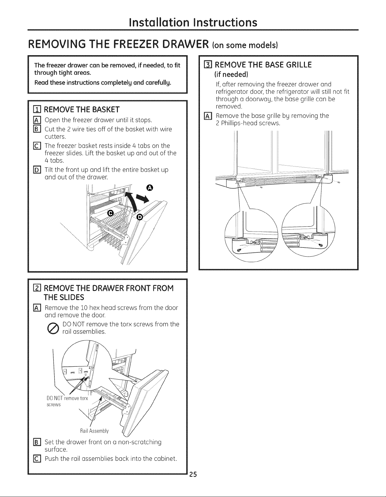
REMOVING THE FREEZER DRAWER Ionsome models)
The freezer drawer can be removed, if needed, to fit
through tight areas.
Read these instructions completelg and carefullg.
m REMOVE THE BASKET
[] Open the freezer drawer until it stops.
r_ cut the 2 wire ties off of the basket with wire
cutters.
[] The freezer basket rests inside 4 tabs on the
freezer slides. Lift the basket up and out of the
4 tabs.
FD] Tilt the front up and lift the entire basket up
and out of the drawer.
\\
\.
\
\
\,
\
\
[_] REMOVE THE BASE GRILLE
(if needed}
If, after removing the freezer drawer and
refrigerator door, the refrigerator will still not fit
through a doorwag, the base grille can be
removed.
r_ Remove the base grille bg removing the
2 Phillips-head screws.
[] REMOVE THE DRAWER FRONT FROM
THE SLIDES
[_ Remove the 10 hex head screws from the door
and remove the door.
DO NOT remove the torx screws from the
rail assemblies.
l
DONOTremovetorx
screws
RailAssembly
[] Set the drawer front non-scratching
surface.
r_ Push the rail assemblies back into the cabinet.
on a
25
Installation Instructions
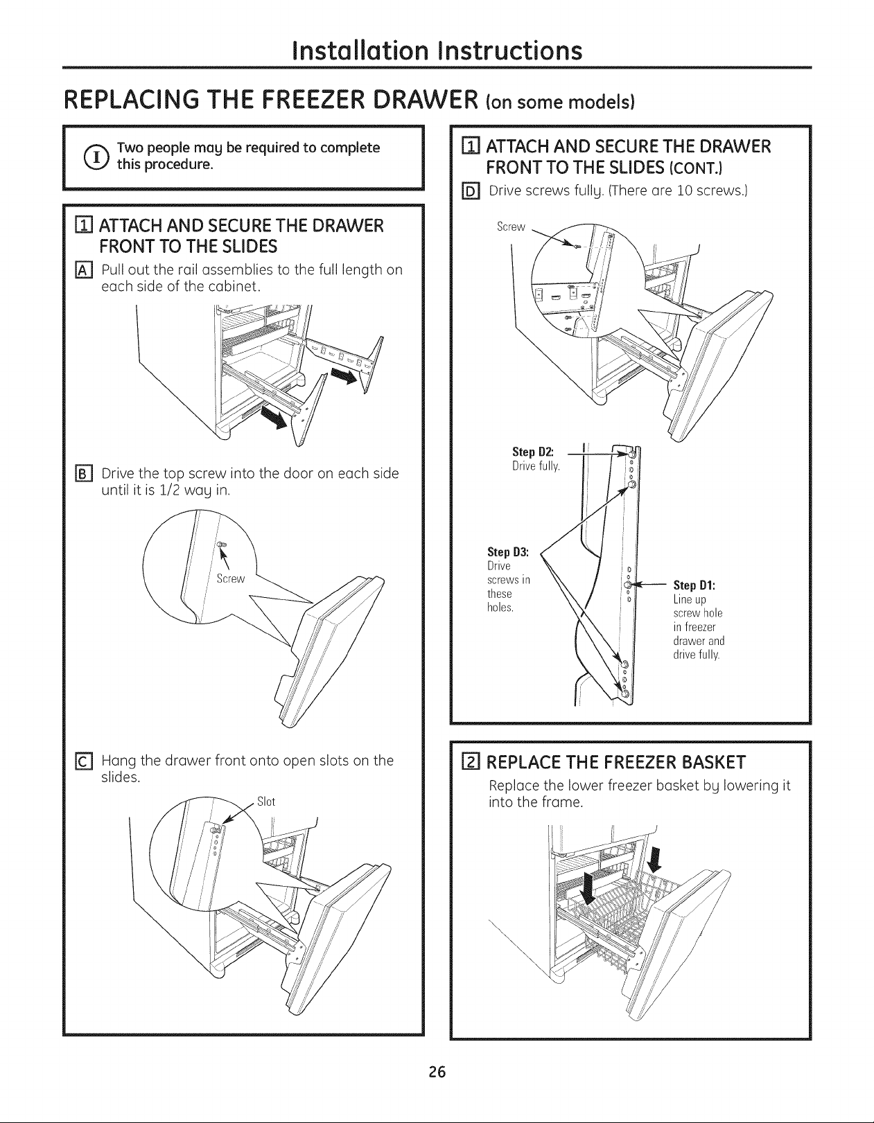
REPLACING THE FREEZER DRAWER Consome models)
I'_ ATTACH AND SECURETHE DRAWER
Two people mag be required to complete
this procedure.
FRONT TO THE SLIDES (CONT.)
r_ Drive screws fullg. (There are 10 screws.)
m ATTACH AND SECURETHE DRAWER
FRONT TO THE SLIDES
[_ Pull out the rail assemblies to the full length on
each side of the cabinet.
r_ Drive the top screw into the door on each side
until it is 1/2 wag in.
Screw
Step D2: I
Drivefully.
Step D3:
Drive
screwsin
these
holes.
Step Dl:
Lineup
screwhole
infreezer
drawerand
drivefully.
r_ Hang the drawer front onto open slots on the
slides.
[] REPLACE THE FREEZER BASKET
Replace the lower freezer basket bg lowering it
into the frame.
\.
\
\
26
Installation Instructions
REVERSINGTHE DOOR SWING {Single Door Refrigerator Models only)
IMPORTANT NOTES
When reversing the door swing:
NOTE: Door swing is not reversible on stainless steel
models.
• Read the instructions all the way through before
starting.
• Parts ore included in the door hinge kit.
• Handle parts carefully to avoid scratching paint.
• Set screws down by their related parts to avoid
using them in the wrong places.
• Provide a non-scratching work surface for the doors.
IMPORTANT: Once you begin, do not move the cabinet
until door-swing reversal iscompleted.
These instructions are for changing the hinges from
the right side to the left side-if you ever want to
change the hinges back to the right side, follow these
same instructions and reverse oil references to left and
right.
• Once door swing isfinalized, ensure the logo badge
is properly aligned and permanently secured to the
door by removing the adhesive cover on the back
side.
NOTE:A replacement logo badge is included in the
hinge kit.
Unplug the refrigerator from its electrical outlet.
Empty all door shelves, including the dairy
compartment.
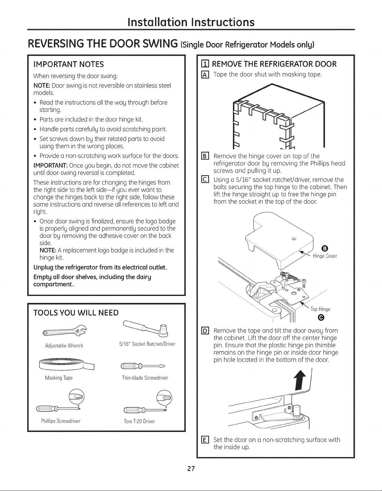
[] REMOVE THE REFRIGERATOR DOOR
r_ Tape the door shut with masking tape.
r_ Remove the hinge cover on top of the
refrigerator door by removing the Phillips head
screws and pulling it up.
rc] using a 5/16" socket ratchet/driver, remove the
bolts securing the top hinge to the cabinet. Then
lift the hinge straight up to free the hinge pin
from the socket in the top of the door.
TOOLS YOU WILL NEED
AdjustableWrench 5/16" SocketRatchet/Driver
MaskingTape Thin-bladeScrewdriver
PhillipsScrewdriver TorxT-20Driver
@ Remove the tape and tilt the door away from
the cabinet. Lift the door off the center hinge
pin. Ensure that the plastic hinge pin thimble
remains on the hinge pin or inside door hinge
pin hole located in the bottom of the door.
r_ set the door on a non-scratching surface with
the inside up.
27
Installation Instructions
REVERSINGTHE DOOR SWING {cont.}
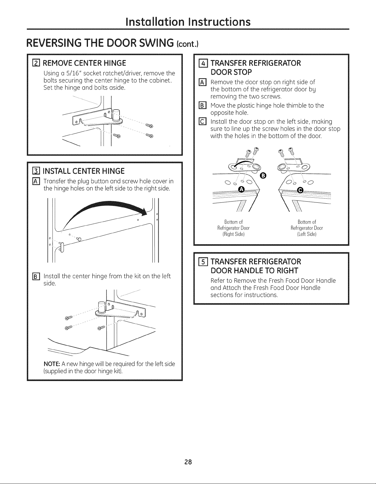
[_[] REMOVE CENTER HINGE
Using a 5/16" socket ratchet/driver, remove the
bolts securing the center hinge to the cabinet.
Set the hinge and bolts aside.
[] INSTALL CENTER HINGE
r_ Transfer the plug button and screw hole cover in
the hinge holes on the left side to the right side.
e
e.
TRANSFER REFRIGERATOR
DOOR STOP
Remove the door stop on right side of
the bottom of the refrigerator door bg
removing the two screws.
Hove the plastic hinge hole thimble to the
opposite hole.
Install the door stop on the left side, making
sure to line up the screw holes in the door stop
with the holes in the bottom of the door.
Bottomof Bottomof
RefrigeratorDoor RefrigeratorDoor
(RightSide) (LeftSide)
r_ Install the center hinge from the kit on the left
side.
_
NOTE: A new hinge will be required for the left side
(supplied in the door hinge kit).
[_ TRANSFER REFRIGERATOR
DOOR HANDLE TO RIGHT
Refer to Remove the Fresh Food Door Handle
and Attach the Fresh Food Door Handle
sections for instructions.
28
Installation Instructions
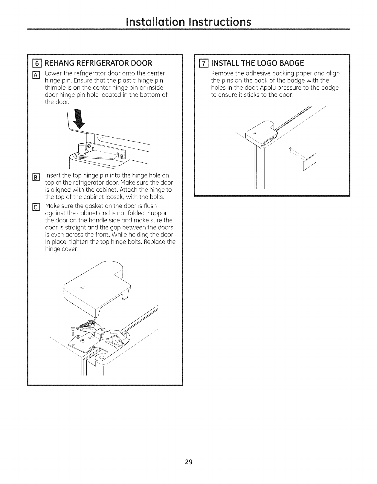
_-I REHANG REFRIGERATOR DOOR
[_ Lower the refrigerator door onto the center
hinge pin. Ensure that the plastic hinge pin
thimble is on the center hinge pin or inside
door hinge pin hole located in the bottom of
the door.
Insert the top hinge pin into the hinge hole on
top of the refrigerotor door. Make sure the door
is oligned with the cabinet. Attoch the hinge to
the top of the cobinet Iooselg with the bolts.
Make sure the gosket on the door is flush
©
ogoinst the cobinet ond is not folded. Support
the door on the hondle side ond moke sure the
door is stroight ond the gop between the doors
is even ocross the front. While holding the door
in ploce, tighten the top hinge bolts. Reploce the
hinge cover.
INSTALL THE LOGO BADGE
Remove the odhesive bockinc paper ond olign
the pins on the bock of the bodge with the
holes in the door. Applg pressure to the bodge
to ensure it sticks to the door.
29

Installation Instructions
REMOVING THE
DOORS {Double Door Refrigerator Models only)
IMPORTANT NOTES
NOTE: Door swing is not reversible.
• Read the instructions all the way through before
starting.
Handle parts carefully to avoid scratching paint.
Set screws down by their related parts to avoid
using them in the wrong places.
Provide a non-scratching work surface for the
doors.
IMPORTANT: Once you begin, do not move the
cabinet.
These instructions are for removing the doors.
Unplug the refrigerator from its electrical outlet,
Empty all door shelves, including the dairy
compartment.
TOOLS YOU WILL NEED
[_] REMOVE THE
REFRIGERATOR DOORS
r_ Tape the doors shut with masking tape.
j/J/j/j
(forwaterdispensermodels)
r_ start with right-hand door first: Remove the
screw securing the center hinge cover, lift the
hinge cover and place to the side on top of the
refrigerator.
Remove_
AdjustableWrench"
MaskingTape
3/8" and 10mmSocket
Thin-bladeScrewdriver
@
PhillipsScrewdriver
Ratchet/Driver
(forwater dispenser models)
r_ Remove water coupling and power coupling.
Water Coupling
Remove the metal spring clip. __
Use a screwdriver to push the __
red plastic locking clip down _ ) I
and off. _ I I
Power Coupling
Black mark flush
with collar
assembly
Pullapart power
coupling to
disconnect
3O
 Loading...