

Page 1
Installation
Instructions
If you have any questions, call GE Appliances at 800.GE.CARES
(800.432.2737)
In Canada, call 800.561.3344
BEFORE YOU BEGIN
Read these instructions completely and carefully.
or visit our Website at: GEAppliances.com
or visit www.GEAppliances.ca
WARNING
Dryer
• IMPORTANT – Save these instructions for
local electrical inspector’s use.
• IMPORTANT – Observe all governing
codes and ordinances.
• Install the clothes dryer according to the
manufacturer’s instructions and local codes.
• Note to Installer – Be sure to leave these
instructions with the Consumer.
• Note to Consumer – Keep these instructions for
future reference.
• Clothes dryer installation must be performed by a
qualified installer.
• This dryer must be exhausted to the outdoors.
• Before the old dryer is removed from service or
discarded, remove the dryer door.
• Service information and the wiring diagram are
located in the control console.
• Do not allow children on or in the appliance. Close
supervision of children is necessary when the
appliance is used near children.
• Proper installation is the responsibility of the installer.
• Product failure due to improper installation is not
covered under the Warranty.
• Install the dryer where the temperature is above
50°F for satisfactory operation of the dryer control
system.
• Remove and discard existing plastic or metal foil
duct and replace with UL-listed duct.
If you are planning to stack the washer and dryer, order
Stacking Kit number GFA28KITN to be used for this
dryer. Kit sold separately.
- Risk of Fire
• Clothes dryer installation must be performed by a
qualified installer.
• Install the clothes dryer according to these
instructions and local codes.
• DO NOT install a clothes dryer with flexible plastic
venting materials. If flexible metal (semi-rigid or
foil-type) duct is installed, it must be UL-listed and
installed in accordance with the instructions found
in “Connecting the Dryer to House Vent” later in
this manual. Flexible venting materials are known
to collapse, be easily crushed and trap lint. These
conditions will obstruct dryer airflow and increase
the risk of fire.
• DO NOT install or store this appliance in any
location where it could be exposed to water or
weather.
• To reduce the risk of severe injury or death, follow
all installation instructions.
• Save these instructions. (Installers: Be sure to
leave these instructions with the customer.)
FOR GAS DRYERS ONLY
In the Commonwealth of Massachusetts,
the following installation instructions apply:
• Installation must be performed by a qualified or
licensed contractor, plumber, or gasfitter qualified
or licensed by the State.
• If using a ball valve, it shall be a T-handle type.
• A flexible gas connector, when used, must not
exceed 4 feet (1.2 m).
14 49-3000386 Rev 0
Page 2
Installation Instructions
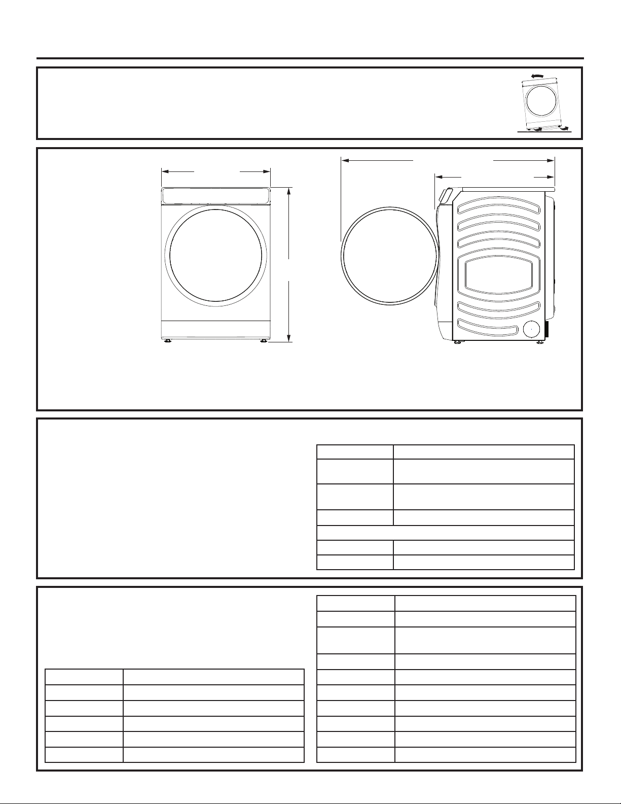
UNPACKING YOUR DRYER
Tilt the dryer sideways and remove the foam shipping pads by pulling at the sides and breaking them
away from the dryer legs. Be sure to remove all of the foam pieces around the legs.
Remove the bag containing the literature. Consider recycling options for your appliance packaging material.
DRYER
28”
(71.2 cm)
DIMENSIONS
*39-3/4”
(101 cm)
Front View
*NOTE: With leveling legs retracted: 39-3/4 (101 cm).
With leveling legs fully extended: 40-5/8 (103.1 cm).
With Optional Pedestal: 55-1/2” (141 cm) Min. - 56-5/8” (143.8 cm) Max.
Stacked: 79-1/8” (201 cm).
STEAM WATER HOSES (for steam dryer models only):
GE Appliances strongly recommends the use of factory
specified parts. These hoses are manufactured and tested
to meet GE Appliances specifications.
GE Appliances strongly recommends the use of new water
supply hoses. Hoses degrade over time and need to be
replaced every 5
and water damage.
Parts and Accessories
Order on-line at GEApplianceparts.com, 24 hours a day
or by phone at 877.959.8688 during normal business hours.
years to reduce the risk of hose failures
Part Number Accessory
WE25X20060
WE49X25794
WE1M847 Long Hose
OR SEPARATELY
WE1M847 Long Hose and
WE1M848 Short Hose
Complete Kit (hoses, Y-adapter, washers)
or
Kit (Short hose, Y-adapter, washers)
and
54-1/4” (137.8 cm)
31-3/8” (79.7 cm)
Side View
ACCESSORIES:
Order on-line at GEApplianceparts.com, 24 hours a day or
by phone at 877.959.8688 during normal business hours.
Part Number Accessory
GFR0728SNWW
GFR0728PNSN
GFR0728PNRS Royal Sapphire Riser
GFR0728PNDG
GFR0728PTDS Black Slate Riser
49-3000386 Rev 0 15
White Riser
Satin Nickel Riser
Diamond Gray Riser
Part Number Accessory
GFA28KITN Stacking Kit for Dryer over Washer
GFA28DSVN
(WE16X29317)
PM08X10085
WE02X29449
GFP1528SNWW
GFP1528PNSN
GFP1528PNRS Royal Sapphire Pedestal
GFP1528PNDG Diamond Gray Pedestal
GFP1528PTDS Black Slate Pedestal
Dryer Venting Kit
Flexible Metal Dryer Transition Duct
Clothes Dryer Drying Rack
White Pedestal
Satin Nickel Pedestal
Page 3
Installation Instructions
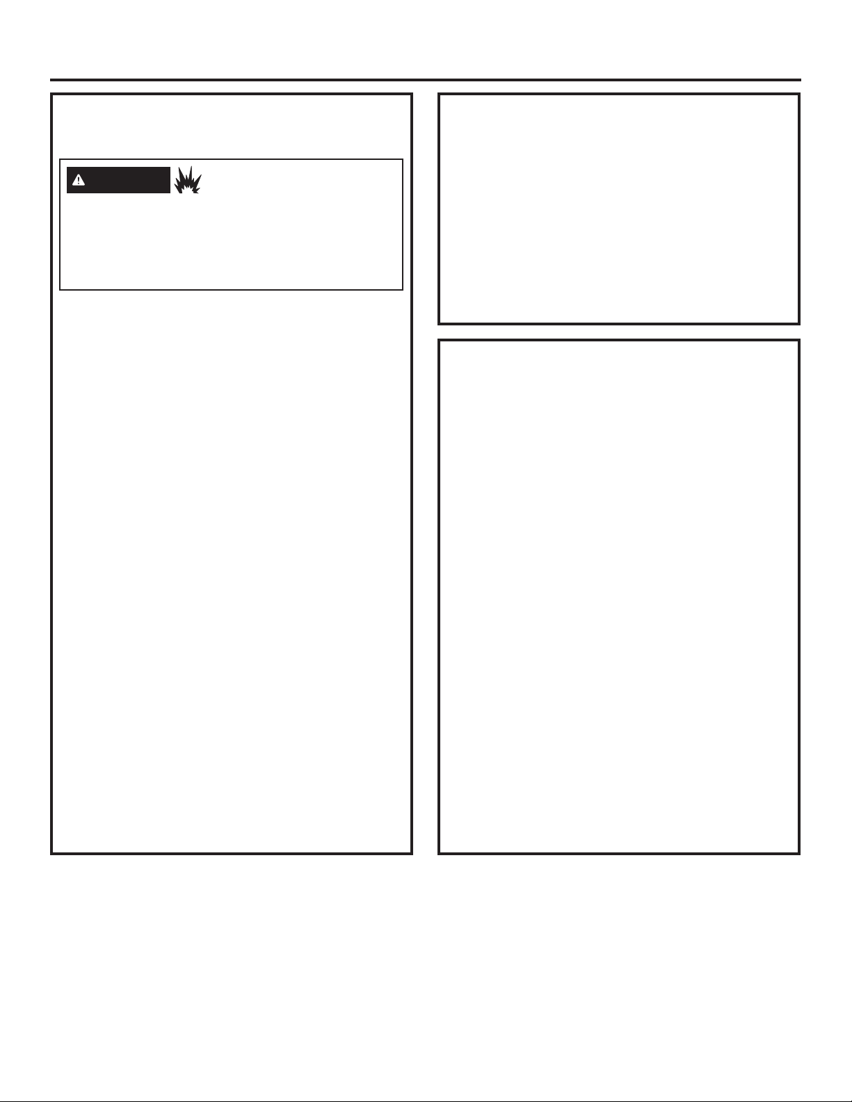
REQUIREMENTS FOR ALCOVE OR
CLOSET INSTALLATION
WARNING
Keep flammable materials and vapors, such as gasoline,
away from dryer.
Place dryer at least 18” (46 cm) above the floor for a
garage installation.
Failure to do so can result in death, explosion, or fire.
• The dryer MUST be vented to the outdoors.
• Minimum clearance between dryer cabinet and
adjacent walls or other surfaces is:
0” (0 cm) either side*
0” (0 cm) front
0” (0 cm) rear
0”
* For improved performance, a 1/2” (12.7 mm)
clearance is suggested on each side.
• The rear of the dryer should face a wall.
• Consideration must be given to provide adequate
clearance for installation and service.
• Closet doors must be louvered or otherwise
ventilated and have at least 60 square inches (387
cm2) of open area. If the closet contains both a
washer and a dryer, doors must contain a minimum
of 120 square inches (774 cm2) of open area.
NOTE: WHEN THE EXHAUST DUCT IS LOCATED AT
THE REAR OF THE DRYER, THE CONFIGURATION
OF THE DUCTING MAY REQUIRE GREATER
CLEARANCE.
Gas Dryers Only:
• No other fuel burning appliance shall be installed in
the same closet as a gas dryer.
• The dryer must be disconnected from the gas
supply piping during pressure testing at pressures
greater than 1/2 psi (3.5 kPa).
• A 1/8” (3.2 mm) NPT minimum plugged tapping,
accessible for test gauge connection, must be
installed immediately upstream of the gas supply
connection to the dryer.
(0 cm)
- Explosion Hazard
top
MINIMUM CLEARANCE OTHER
THAN ALCOVE OR CLOSET
INSTALLATION
Minimum clearance to combustible surfaces and for
air opening are: 0” (0 cm) both sides*, 0” (0 cm) rear
and 0” (0 cm) top.
* For improved performance, a 1/2” (12.7 mm)
clearance is suggested on each side.
The rear of the dryer should face a wall.
Consideration must be given to provide adequate
clearance for installation and service.
MOBILE OR MANUFACTURED
HOME INSTALLATION
• Installation MUST conform to the
MANUFACTURED HOME CONSTRUCTION
AND SAFETY STANDARD, TITLE 24, PART
3280 or STANDARD FOR MOBILE HOMES
CAN/CSA-Z240 MH, or, when such standards
are not applicable, with AMERICAN NATIONAL
STANDARD FOR MOBILE HOME, ANSI/NFPA
NO. 501B.
• The dryer MUST be vented to the outdoors.
• The exhaust vent MUST be securely fastened to a
non-combustible portion of the mobile home.
• The vent MUST NOT be terminated beneath a
mobile or manufactured home.
• The vent duct material MUST BE METAL.
• KIT 14-D346-33 MUST be used to attach the dryer
securely to the structure.
• The vent MUST NOT be connected to any other
duct, vent or chimney.
• DO NOT use sheet metal screws or other
fastening devices which extend into the interior of
the exhaust vent.
• Provide an opening with a free area of at least 25
square inches (63 cm
air into the dryer room.
• See the sections for electrical connection information.
2
) for introduction of outside
16 49-3000386 Rev 0
Page 4
Installation Instructions
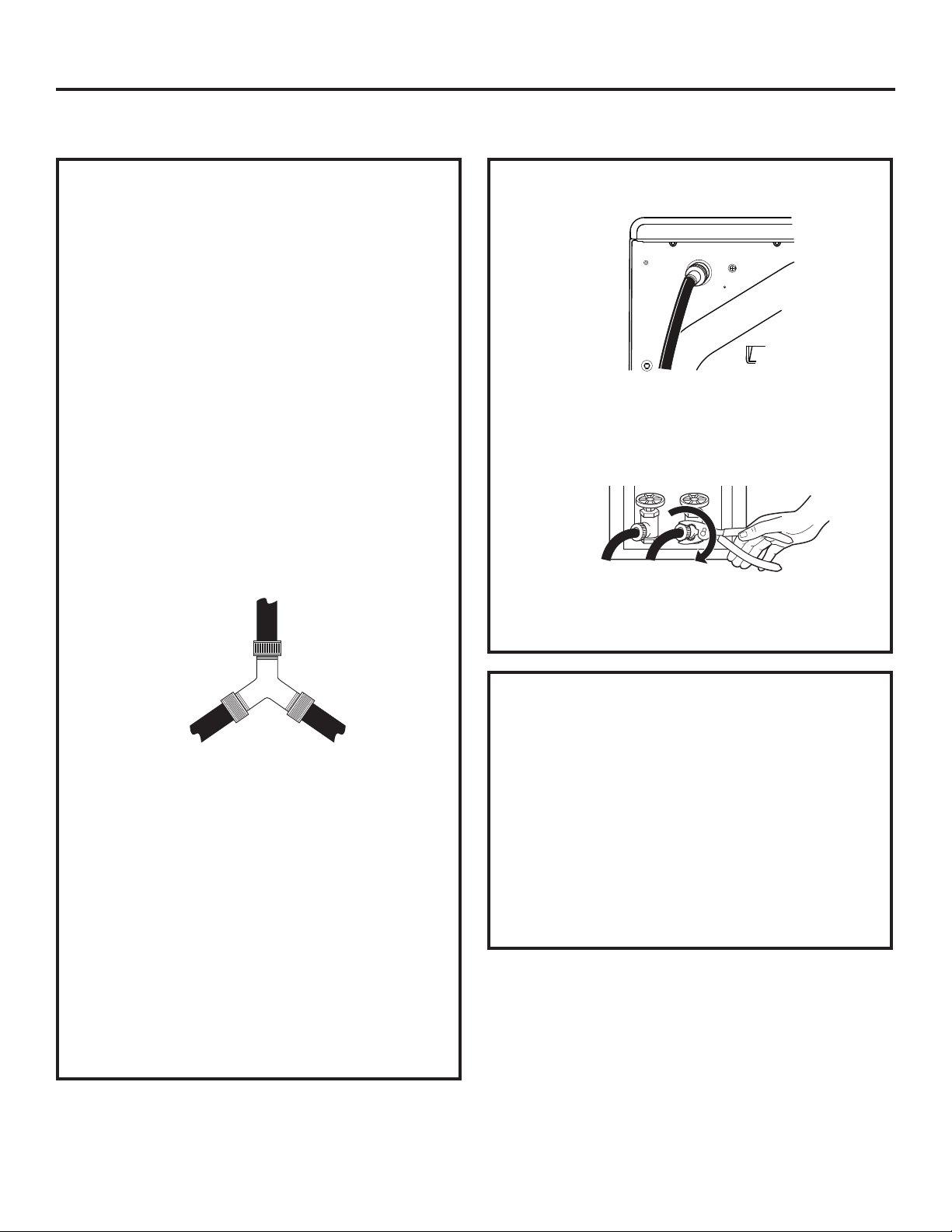
CONNECTING INLET HOSES (for steam dryer models only)
CONNECTING INLET HOSES
To produce steam, the dryer must connect to
the cold water supply. Since the washer must
also connect to the cold water, a “Y” connector
is inserted to allow both inlet hoses to make that
connection at the same time.
NOTE: Use new inlet hoses; never use old
hoses.
1. Turn the cold water faucet off. Remove the
washer inlet hose from the washer fill valve
connector (cold).
2. Ensure the rubber flat washer is in place and
attach one female coupling of the short hose
provided onto the washer fill valve connector.
Tighten by hand until firmly seated.
3. Attach one male end of the “Y” connector to
the other female coupling of the short hose.
Ensure the rubber flat washer is in place.
Tighten by hand until firmly seated.
CONNECTING INLET HOSES (cont.)
7. Using pliers, tighten all the couplings with an
additional two–thirds turn.
NOTE: Do not overtighten. Damage to the
couplings may result.
8. Turn the water faucet on.
9. Check for leaks around the ‘’Y’’ connector,
faucet and hose couplings.
4. Insert the filter screen in the coupling of the
washer’s inlet hose. If a rubber flat washer is
already in place remove it before installing the
filter screen. Attach this coupling to one male
end of the ‘’Y’’ connector. Tighten by hand until
firmly seated.
5. Ensure the rubber flat washer is in place
and attach a 4 ft. (1.2 m) to 6 ft. (1.8 m) long
water inlet hose (may need to be purchased
separately) to one male end of the ‘’Y’’
connector. Tighten by hand until firmly seated.
6. Ensure the rubber flat washer is in place and
attach the other end of the dryer’s long inlet
hose to the fill valve connector at the bottom
of the dryer back panel. Tighten by hand until
firmly seated.
WATER SUPPLY REQUIREMENTS
Hot and cold water faucets MUST be installed
within 42 in. (107 cm) of your washer’s water
inlet. The faucets MUST be 3/4” (19.1 mm)
garden hose-type so inlet hoses can be
connected. Water pressure MUST be between
10 and 120 pounds per square inch. Your
water department can advise you of your water
pressure.
NOTE: A water softener is recommended
to reduce buildup of scale inside the steam
generator if the home water supply is very hard.
49-3000386 Rev 0 17
Page 5
Installation Instructions
Ŷ
Ŷ
Ŷ
Ŷ
Ŷ
Ŷ
Ŷ
Ŷ
Ŷ
Ŷ
Ŷ
Ŷ
Ŷ
Ŷ
Ŷ
Ŷ
Ŷ
Ŷ
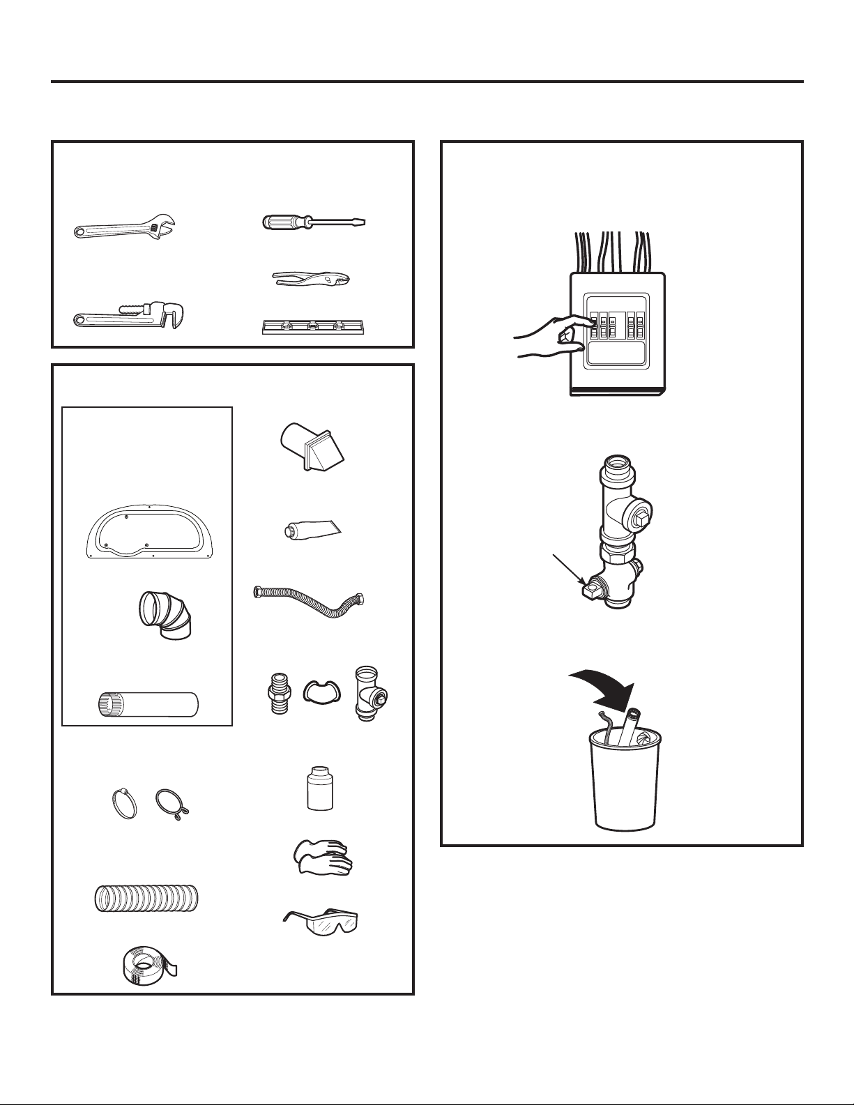
CONNECTING A GAS DRYER (skip for electric dryers)
TOOLS YOU WILL NEED
Ŷ
10” (25.40 cm)
Adjustable wrenches (2)
Ŷ
8” (20.32 cm)
Pipe wrench
Ŷ
Flat-blade
screwdriver
Ŷ
Slip-joint pliers
Ŷ
Level
MATERIALS YOU WILL NEED
Ŷ
GFA28DSVN Kit
(All parts included in
this Kit or parts may be
purchased separately)
Ŷ
Access Panel
Ŷ
4” (10.2 cm) dia. metal
elbow
Exhaust hood
Ŷ
Pipe compound or
PTFE tape
Ŷ
Flexible gas line
connector
• Before beginning the installation, turn off the circuit
breaker(s) or remove the dryer’s circuit fuse(s) at
the electrical box. Be sure the dryer
cord is unplugged from the wall.
• Turn the dryer’s gas shut-off valve in the supply line
to the OFF position.
Shut-off
Valve
Ŷ
4” (10.2 cm) dia. metal
duct (recommended)
Ŷ
4” (10.2 cm) Duct
clamps (2) or 4” (10.2
cm) spring clamps (2)
Ŷ
4” (10.2 cm) dia.,
UL-listed flexible
metal duct (if needed)
Ŷ
Aluminum foil tape
Ŷ
Gas pipe adapters (2),
elbow and pipe plug
Ŷ
Soap solution for
leak detection
Ŷ
Gloves
Ŷ
Safety glasses
• Disconnect and discard old flexible gas connector
and ducting material.
18 49-3000386 Rev 0
Page 6
Installation Instructions
CONNECTING A GAS DRYER (cont.)
GAS REQUIREMENTS
WARNING
• Use a new CSA International approved flexible
gas supply line. Never reuse old flexible
connectors.
• Install an individual manual shut-off valve
within 6ft. of the dryer in accordance with the
National Fuel Gas Code, ANSI Z223.1/NFPA
54.
• Securely tighten all gas connections.
• If connected to LP gas, have a qualified
person make sure gas pressure DOES NOT
exceed 13” (33 cm) water column.
• Examples of a qualified person include:
licensed heating personnel, authorized gas
company personnel, and authorized service
personnel.
• Failure to do so can result in death,
explosion, or fire.
• The installation must conform with local
codes, or in the absence of local codes, with
the National Fuel Gas Code, ANSI Z223.1/
NFPA 54, or the Natural Gas and Propane
Installation Code, CSA B149.1.
- Explosion Hazard
GAS SUPPLY
• A 1/8” (3.2 mm) National Pipe Taper thread
plugged tapping, accessible for test gauge
connection, must be installed immediately
upstream of the gas supply connection to the
dryer. Contact your local gas utility should you
have questions on the installation of the plugged
tapping.
• Supply line is to be 1/2” (12.7 mm) rigid pipe and
equipped with an accessible shutoff within 6 feet
(1.8 m) of, and in the same room with, the dryer.
• Use pipe thread compound appropriate for
natural or LP gas or use PTFE tape.
• Connect flexible metal connector to dryer and
gas supply.
WARNING
FOR USE WITH NATURAL GAS ONLY
Dryer as produced by manufacturer is to be used
only with a natural gas supply. A manufacturersupplied conversion kit is required to convert this
dryer for propane gas supply. Use propane
conversion kit WE25M87
made by properly trained and qualified personnel
in accordance with local codes and ordinances.
- Fire Hazard
gas
. Conversion must be
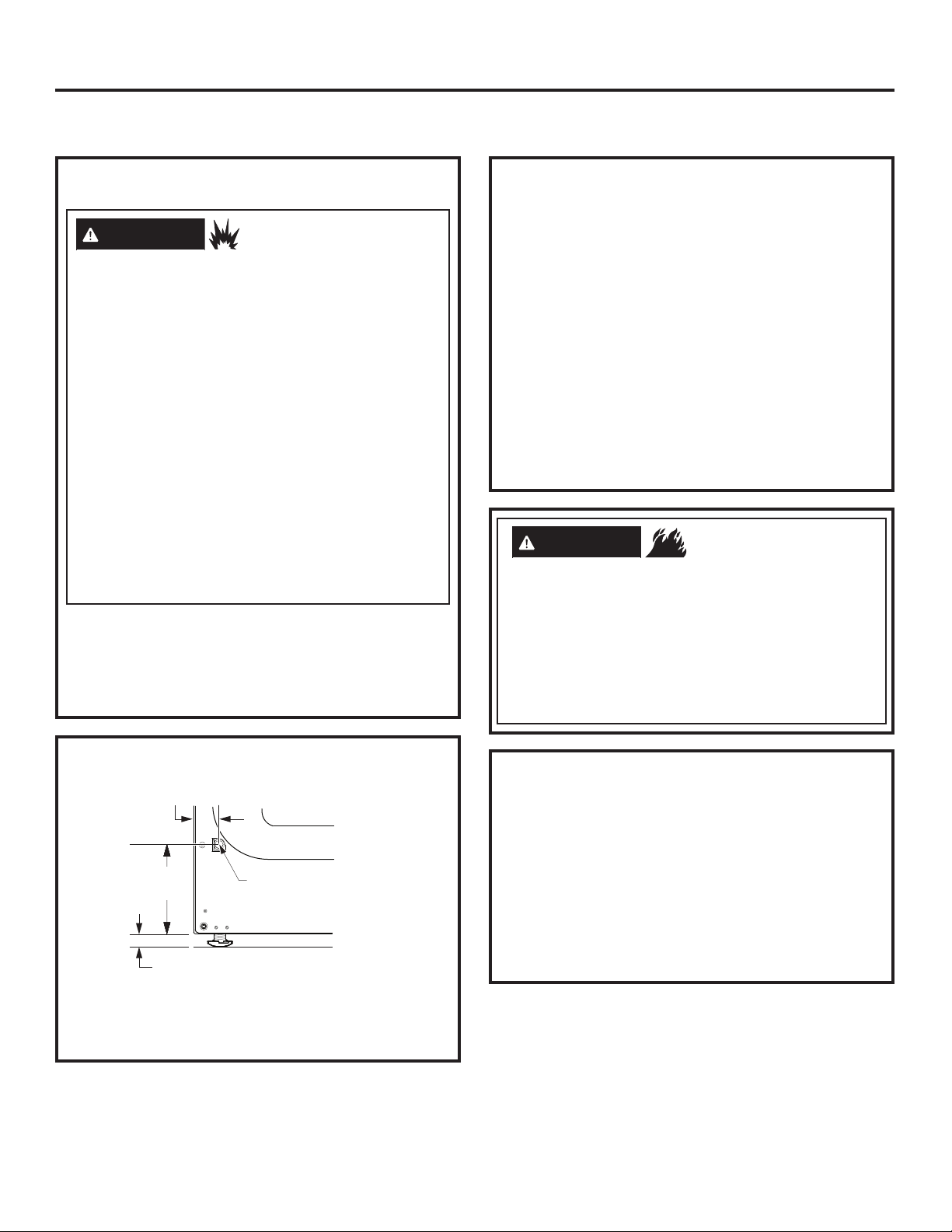
DRYER GAS SUPPLY CONNECTION
1-5/8” (4.16 cm)
5-3/4”
(14.57 cm)
You must use with this dryer a flexible metal connector
(listed connector ANSI Z21.24 / CSA 6.10). The length
of the connect shall not exceed 4 ft. (1.2 m).
49-3000386 Rev 0 19
NOTE: Add to vertical dimension the
GLVWDQFHEHWZHHQFDELQHWERWWRPWRÀRRU
3/8” (9.6 mm) NPT
MALE THREAD
GAS SUPPLY
ADJUSTING FOR ELEVATION
• Gas clothes dryers input ratings are based on
sea level operation and need not be adjusted for
operation at or below 2000 ft. (610 m) elevation.
For operation at elevations above 2000 ft. (610 m),
input ratings should be reduced at a rate of 4
percent for each 1000 ft. (305 m) above sea level.
• Installation must conform to local codes and
ordinances or, in their absence, the NATIONAL
FUEL GAS CODE, ANSI Z223.
Page 7
Installation Instructions
CONNECTING A GAS DRYER (cont.)
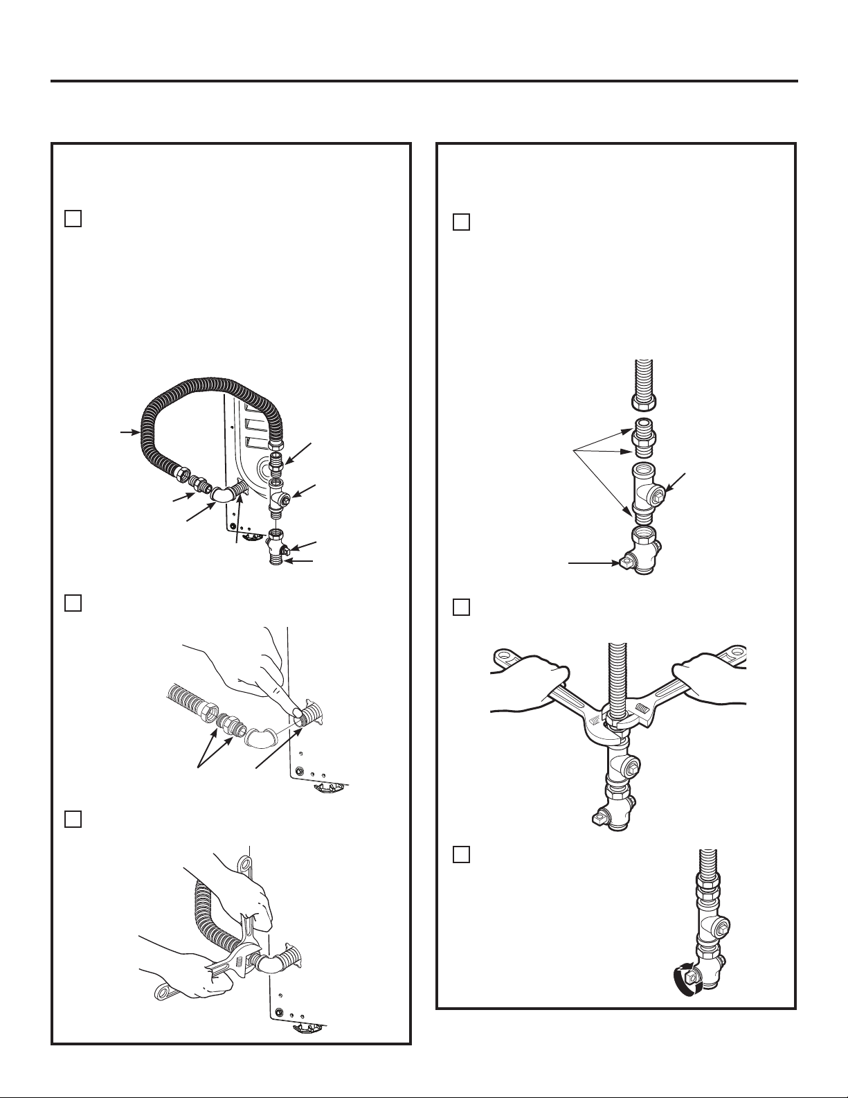
CONNECTING THE DRYER TO
THE GAS SUPPLY
Install a female 3/8” (9.6 mm) NPT elbow at
A
the end of the dryer gas inlet.
Install a 3/8” (9.6 mm) flare union adapter to
the female elbow.
IMPORTANT: Use a pipe wrench to securely
hold on to the end of the dryer gas inlet to
prevent twisting the inlet.
NOTE: Apply pipe compound or PTFE tape to
the threads of the adapter and dryer gas inlet.
New Metal
Flexible Gas
Line Connector
Adapter
Elbow
Items not supplied
Attach the flexible metal gas line connector to
B
3/8” (9.6 mm)
NPT
the adapter.
Adapter
1/8” (3.2 mm)
NPT Pipe Plug
for Checking
Gas Inlet
Pressure
Shut-Off Valve
Pipe size at
least 1/2” (12.7
mm)
CONNECTING THE DRYER TO
THE GAS SUPPLY (cont.)
Install a 1/8” (3.2 mm) NPT plugged tapping
D
to the dryer gas line shut-off valve for
checking gas inlet pressure.
Install a flare union adapter to the plugged
tapping.
NOTE: Apply pipe compound or PTFE tape
to the threads of the adapter and plugged
tapping.
Apply pipe compound
or PTFE tape to all
male threads.
Shut-Off
Valve
Tighten all connections, using two adjustable
E
wrenches. Do not overtighten.
Plugged
Tapping
Apply pipe compound to the
adapter and dryer gas inlet.
Tighten the flexible gas line connection, using
C
two adjustable wrenches.
Open the gas shut-off valve.
F
20 49-3000386 Rev 0
Page 8
Installation Instructions
CONNECTING A GAS DRYER (cont.)
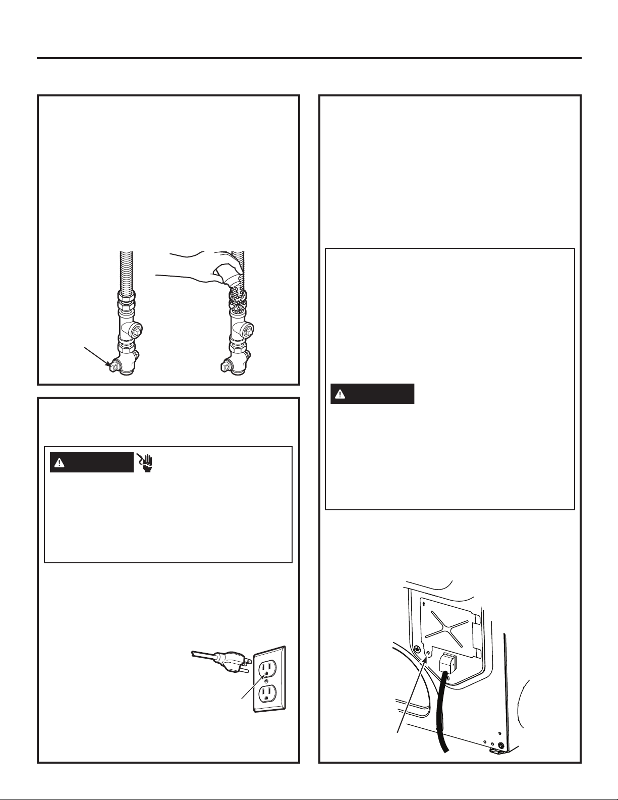
TEST FOR LEAKS
Never use an open flame to test for gas leaks.
Check all connections for leaks with soapy solution or
equivalent.
Apply a soap solution. The leak test solution must not
contain ammonia, which could cause damage to the
brass fittings.
If leaks are found, close the valve, retighten the joint
and repeat the soap test.
Open Gas
Valve
ELECTRICAL CONNECTION
INFORMATION FOR GAS DRYERS
WARNING
Plug into a grounded 3 prong outlet.
DO NOT remove ground prong.
DO NOT use an adapter.
DO NOT use an extension cord.
Failure to do so can result in death, fire or
electrical shock.
• Circuit – Individual properly polarized and grounded
15 or 20 amp circuit breaker or time-delay fuse.
• Power Supply – 2-wire plus ground, 120 Volt, single
phase, 60 Hz, alternating current.
• Outlet Receptacle – Properly grounded 3-prong
receptacle to be located
so the power cord is
accessible when the dryer
is in an installed position.
If a 2-prong receptacle is
present, it is the owner’s
responsibility to have a
licensed electrician replace
it with a properly grounded 3-prong grounding type
receptacle.
- Electrical Shock Hazard
Ensure proper
ground exists
before use.
ELECTRICAL CONNECTION
INFORMATION FOR GAS DRYERS
(cont.)
• Dryer must be electrically grounded in accordance
with local codes and ordinances, or in the absence
of local codes, with the latest edition of the
NATIONAL ELECTRICAL CODE, ANSI/NFPA
NO. 70 or CANADIAN ELECTRICAL CODE, CSA
C22.1. Check with a licensed electrician if you are
not sure that the dryer is properly grounded.
GROUNDING INSTRUCTIONS
This dryer must be grounded. In the event of a
malfunction or breakdown, grounding will reduce
the risk of electric shock by providing a path of
least resistance for electric current. This dryer
uses a cord having an equipment-grounding
conductor and a grounding plug. The plug must
be plugged into an appropriate outlet that is
properly installed and grounded in accordance
with all local codes and ordinances.
WARNING
can result in a risk of electric shock. Check with a
qualified electrician, or service representative or
personnel, if you are in doubt as to whether the
appliance is properly grounded. DO NOT modify
the plug on the power supply cord. If it will not
fit the outlet, have a proper outlet installed by a
qualified electrician.
SAVE THESE INSTRUCTIONS
• If required by local codes, an external 18 gauge
or larger copper ground wire (not provided) may
be added. Attach to dryer cabinet with a #8-18 x
1/2” (12.7 mm) sheet metal screw (available at any
hardware store) to rear of dryer as illustrated.
Ground
Screw
Improper connection of the
equipment-grounding conductor
49-3000386 Rev 0 21
Page 9
Installation Instructions
Ŷ
Ŷ
Ŷ
Ŷ
Ŷ
Ŷ
Ŷ
Ŷ
Ŷ
Ŷ
Ŷ
Ŷ
Ŷ
Ŷ
Ŷ
CONNECTING AN ELECTRIC DRYER
(Skip for gas dryers and if your dryer already has a power cord attached)
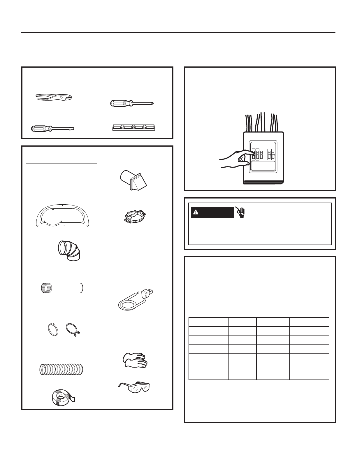
TOOLS YOU WILL NEED
Slip-joint pliers
Flat-blade
screwdriver
Phillips
screwdriver
Level
MATERIALS YOU WILL NEED
Ŷ
GFA28DSVN Kit
(All parts included in
this Kit or parts may be
purchased separately)
Ŷ
Access Panel
Ŷ
4” (10.2 cm) dia. metal
elbow
Ŷ
4” (10.2 cm) dia. metal
duct (recommended)
Ŷ
4” (10.2 cm) Duct
clamps (2) or 4” (10.2
cm) spring clamps (2)
Ŷ
4” (10.2 cm) dia.,
UL-listed flexible
metal duct (if needed)
Ŷ
Aluminum foil tape
Exhaust hood
Ŷ
Metal strain relief
clamp (UL recognized)
Ŷ
Dryer power cord kit
(not provided with
dryer)
UL rated 120/240V,
30A with 3 or 4 prongs.
Identify the plug type
as per the house
receptacle before
purchasing line cord.
Stacking installations
may require a power
cord up to 6 feet
(1.8 m) in length.
Ŷ
Gloves
Ŷ
Safety glasses
Before making the electrical connection, turn off the
circuit breaker(s) or remove the dryer’s circuit fuse(s) at
the electrical box. Be sure the dryer cord is unplugged
from the wall. NEVER LEAVE THE ACCESS COVER
OFF THE TERMINAL BLOCK.
WARNING
Disconnect power supply before servicing.
Replace all parts and panels before operating.
Failure to do so can result in death or electrical shock.
- Electrical Shock Hazard
POWER CORDS
GE Appliances strongly recommends the use of
factory specified parts. Select the power cord to fit your
installation requirements.
NOTE: If your dryer circuit is on a circuit protected by a
GFCI breaker, then 3-wire installation is not permitted.
House wiring and dryer must be configured for 4-wire.
Part Number Type Length Amperage
WX9X2 3-Prong 4 ft. (1.2 m) 30
WX9X3 3-Prong 5 ft. (1.5 m) 30
WX9X4 3-Prong 6 ft. (1.8 m) 30
WX9X18 4-Prong 4 ft. (1.2 m) 30
WX9X19 4-Prong 5 ft. (1.5 m) 30
WX9X20 4-Prong 6 ft. (1.8 m) 30
Order on-line at GEApplianceparts.com today,
24 hours a day or by phone at 877.959.8688 during
normal business hours. In Canada, visit your local
GE Appliances parts distributor or call 800.661.1616
GEAppliances.ca/en/products/parts-filters-accessories.
or
22 49-3000386 Rev 0
Page 10
Installation Instructions
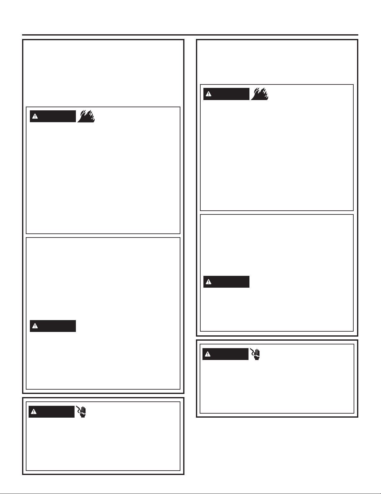
ELECTRICAL CONNECTION
INFORMATION FOR ELECTRIC DRYERS
For electrical connections using a
power cord:
NOTE: If your dryer circuit is on a circuit protected by a
GFCI breaker, then 3-wire installation is not permitted.
House wiring and dryer must be configured for 4-wire.
WARNING
Use a new UL-listed 240V 30 amp dryer power supply
cord with closed ring terminals or spade terminals with
upturned ends.
Use a UL-listed strain relief.
Disconnect power before making electrical connections.
Connect neutral wire (white or center wire) to center
terminal.
Ground wire (green or bare wire) must be connected to
green ground connector.
Connect remaining two supply wires to remaining two
terminals.
Securely tighten all electrical connections.
Replace the terminal block cover.
Failure to do so can result in death, fire or electrical shock.
- Fire Hazard
GROUNDING INSTRUCTIONS
For a grounded, cord-connected dryer: This dryer
must be grounded. In the event of a malfunction or
breakdown, grounding will reduce the risk of electric
shock by providing a path of least resistance for
electric current. This dryer uses a cord having an
equipment-grounding conductor and a grounding
plug. The plug must be plugged into an appropriate
outlet that is properly installed and grounded in
accordance with all local codes and ordinances.
WARNING
result in a risk of electric shock. Check with a qualified
electrician, or service representative or personnel, if
you are in doubt as to whether the appliance is properly
grounded. DO NOT modify the plug on the power supply
cord. If it will not fit the outlet, have a proper outlet
installed by a qualified electrician.
SAVE THESE INSTRUCTIONS
WARNING
Improper connection of the
equipment-grounding conductor can
- Electrical Shock Hazard
ELECTRICAL CONNECTION
INFORMATION FOR ELECTRIC
DRYERS
For direct wire connections:
WARNING
Use 10 gauge copper wire.
Use a UL-listed strain relief.
Disconnect power before making electrical connections.
Connect neutral wire (white or center wire) to center
terminal.
Ground wire (green or bare wire) must be connected to
green ground connector.
Connect remaining two supply wires to remaining two
terminals.
Securely tighten all electrical connections.
Replace the terminal block cover.
Failure to do so can result in death, fire or electrical shock.
- Fire Hazard
GROUNDING INSTRUCTIONS
For a permanently connected dryer: This dryer
must be connected to a grounded metal, permanent
wiring system, or an equipment-grounding conductor
must be run with the circuit conductors and
connected to the equipment-grounding terminal on
the appliance.
WARNING
result in a risk of electric shock. Check with a qualified
electrician, or service representative or personnel, if
you are in doubt as to whether the appliance is properly
grounded.
SAVE THESE INSTRUCTIONS
WARNING
TO PREVENT ELECTRIC SHOCK, DISCONNECT
POWER BEFORE SERVICING.
This dryer should be connected to an individual branch
circuit with 10 gauge copper wire minimum through a
30 amp fuse or circuit breaker. DO NOT fuse neutral.
Use copper conductors only.
Improper connection of the
equipment-grounding conductor can
- Electrical Shock Hazard
TO PREVENT ELECTRIC SHOCK, DISCONNECT
POWER BEFORE SERVICING.
This dryer should be connected to an individual branch
circuit with 10 gauge copper wire minimum through a
30 amp fuse or circuit breaker. DO NOT fuse neutral.
Use copper conductors only.
49-3000386 Rev 0 23
Page 11
Installation Instructions
CONNECTING AN ELECTRIC DRYER (cont.)
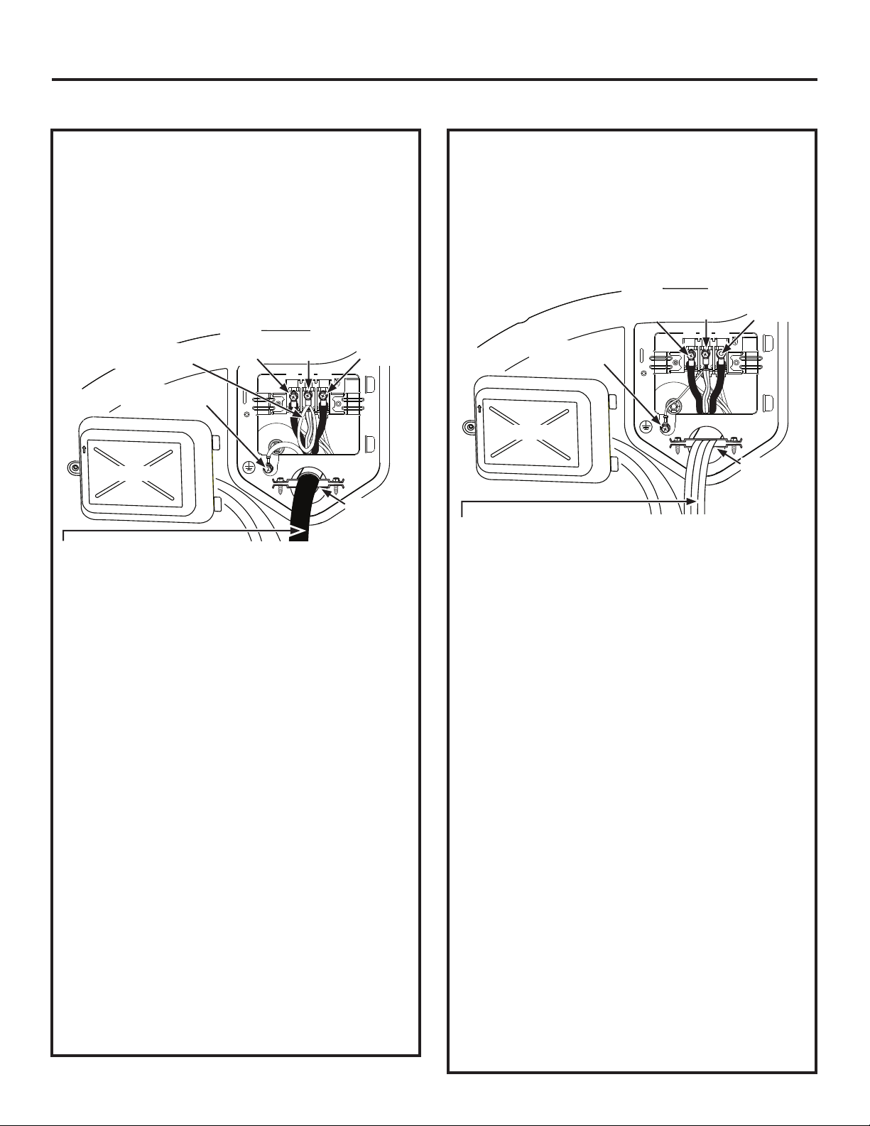
CONNECTING DRYER USING
4-WIRE CONNECTION (MUST
BE USED FOR MOBILE HOME
INSTALLATION)
NOTE: Since January 1, 1996, the National Electrical
Code requires that new constructions use a 4-wire
connection to an electric dryer. A 4-wire cord must
also be used where local codes do not permit grounding
through the neutral. 3-wire connection is NOT for use
on new construction.
Black
Dryer’s White Strap
Looped to Neutral (N)
Green wire from
power cord
Cover
4 #10 AWG minimum copper conductors or 120/240V 30A
power supply cord kit marked for use with dryers and provided
with closed loop or spade terminals with upturned ends (not
supplied).
1. Turn off the circuit breaker(s) (30 amp) or remove
the dryer’s circuit fuse at the electrical box.
2. Be sure the dryer cord is unplugged from the wall
receptacle.
3. Remove the power cord cover located at the lower
back.
4. Remove green ground screw and retain for use
in Step 7. Leave one end of the short white strap
loose until Step 6. Remove center screw (marked
N) in terminal block.
5. Place the UL-recognized metal strain relief clamp
to power cord entry hole. Bring power cord through
strain relief clamp.
6. Connect power cord as follows:
A. Connect the 2 hot lines to the outer screws of the
terminal block (marked L1 and L2).
B. Connect the neutral (white) line and the loose
end of the short white strap to the center of the
terminal block (marked N).
7. Attach ground wire of power cord with the green
ground screw (hole to left of strain relief clamp).
Tighten all terminal block screws (3) securely.
8. Properly secure power cord to strain relief clamp.
9. Reinstall the cover.
or Red
Wire
White
Wire
L1 N L2
NEVER LEAVE THE COVER OFF OF THE
TERMINAL BLOCK.
Black
or Red
Wire
Metal Strain
Relief
Clamp UL
CONNECTING DRYER USING
3-WIRE CONNECTION
NOTE: If your dryer circuit is on a circuit protected by a
GFCI breaker, then 3-wire installation is not permitted.
House wiring and dryer must be configured for 4-wire.
If required, by local code, install external ground (not
provided) to grounded metal, cold water pipe, or other
established ground determined by a qualified electrician.
Black
or Red
Wire
Ground
White Strap
Cover
3 #10 AWG minimum copper conductors or 120/240V 30A
power supply cord kit marked for use with dryers and provided
with closed loop or spade terminals with upturned ends (not
supplied).
3-wire Connection
Not for use in Canada.
DO NOT use for Mobile Home Installations.
NOT for use on new construction.
NOT for use on recreational vehicles.
NOT for use in areas where local codes prohibit
grounding through the neutral conduction.
1. Turn off the circuit breaker(s) (30 amp) or remove
the dryer’s circuit fuse at the electrical box.
2. Be sure the dryer cord is unplugged from the wall
receptacle.
3. Remove the power cord cover located at the lower
back.
4. Place the UL-recognized metal strain relief clamp
to power cord entry hole. Bring power cord through
strain relief clamp.
5. Connect power cord as follows:
A. Connect the 2 hot lines to the outer screws of
the terminal block (marked L1 and L2).
B. Connect the neutral (white) line to the center of
the terminal block (marked N).
6. Be sure ground white strap is connected to green
ground screw on cabinet rear. Tighten all terminal
block screws (3) securely.
7. Properly secure power cord to strain relief clamp.
8. Reinstall the cover.
White
Wire
L1 N L2
NEVER LEAVE THE COVER OFF OF THE
TERMINAL BLOCK.
Black
or Red
Wire
Metal Strain
Relief
Clamp UL
24 49-3000386 Rev 0
Page 12
Installation Instructions
Ŷ
Ŷ
Ŷ
Ŷ
EXHAUSTING THE DRYER
WARNING
This dryer MUST be vented to the outdoors.
Use only 4” (10.2 cm) rigid metal ducting for
the home exhaust duct.
Use only 4" (10.2 cm) rigid metal, UL-listed
flexible metal, or UL-listed metal foil dryer
transition duct to connect the dryer to the
home exhaust.
DO NOT use any plastic to vent the dryer,
this includes the home exhaust duct, dryer
transition duct, or within the dryer.
DO NOT use flexible metal or metal foil ducting
for a home exhaust duct or within the dryer.
DO NOT exhaust into a chimney, kitchen
exhaust, gas vent, wall, ceiling, attic, crawl
space, or concealed space of a building.
DO NOT install a screen in or over the exhaust
duct.
DO NOT install a booster fan in the exhaust duct.
DO NOT use duct longer than specified in the
exhaust length table.
Failure to follow these instructions can result in
death or fire.
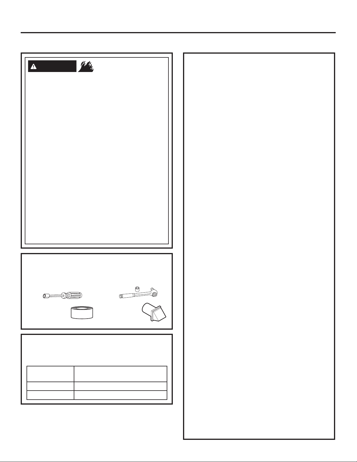
TOOLS AND MATERIALS YOU WILL
NEED TO INSTALL EXHAUST DUCT
Ŷ
1/4" (6.4 mm) Socket &
Nut Driver
Ŷ
Aluminum foil
tape or duct
clamp
PARTS AVAILABLE FROM
GEAPPLIANCEPARTS.COM OR
LOCAL SERVICE ORGANIZATIONS
GFA28DSVN
(WE16X29317)
PM8X85
WX08X10130 4” (10.2 cm) Dryer exhaust clamp
- Fire Hazard
Ŷ
1/4" (6.4 mm) Socket &
Wrench
Ŷ
Vent hood
Dryer Venting Kit
Outdoor exhaust hood
CONNECTING THE DRYER TO
HOUSE VENT
RIGID METAL TRANSITION DUCT
• For best drying performance, a rigid metal transition
duct is recommended.
• Rigid metal transition ducts reduce the risk of
crushing and kinking.
UL-LISTED FLEXIBLE METAL CLOTHES
DRYER TRANSITION DUCT
• If rigid metal cannot be used, then UL-listed flexible
metal clothes dryer transition duct (GE Appliances
part – PM08X10085) can be used.
• Never install transition duct in walls, ceilings, floors
or other enclosed spaces.
• Total length of transition duct should not exceed 8’
(2.4 m).
• For many applications, installing elbows at both
the dryer and the wall is highly recommended (see
illustrations in next section). Elbows allow the dryer
to sit close to the wall without kinking and/or crushing
the transition duct, maximizing drying performance.
• Avoid resting the duct on sharp objects.
UL-LISTED FLEXIBLE METAL (FOIL-TYPE)
TRANSITION DUCT
• In special installations, it may be necessary to
connect the dryer to the home exhaust vent
using flexible metal (foil-type) transition duct. UL–
LISTED universal flexible dryer transition duct
(GE Appliances parts – PM8X73 or WX8X73)
may be used ONLY in installations where rigid
metal or flexible metal transition ducting cannot
be used AND where a 4” (10.2 cm) diameter can
be maintained throughout the entire length of the
transition duct.
• In Canada and the United States, only transition
ducts that comply with “UL 2158A STANDARD
FOR CLOTHES DRYER TRANSITION DUCT”
shall be used.
• Avoid resting the duct on sharp objects.
• For best drying performance:
1. Slide one end of the duct over the clothes
dryer outlet pipe.
2. Secure the duct with a clamp.
3. With the dryer in its permanent position,
extend the duct to its full length. Allow 2” (5.08
cm) of duct to overlap the exhaust pipe. Cut
off and remove excess duct. Keep the duct as
straight as possible for maximum airflow.
4. Secure the duct to the exhaust pipe with the
other clamp.
49-3000386 Rev 0 25
Page 13
Installation Instructions
EXHAUSTING THE DRYER (cont.)
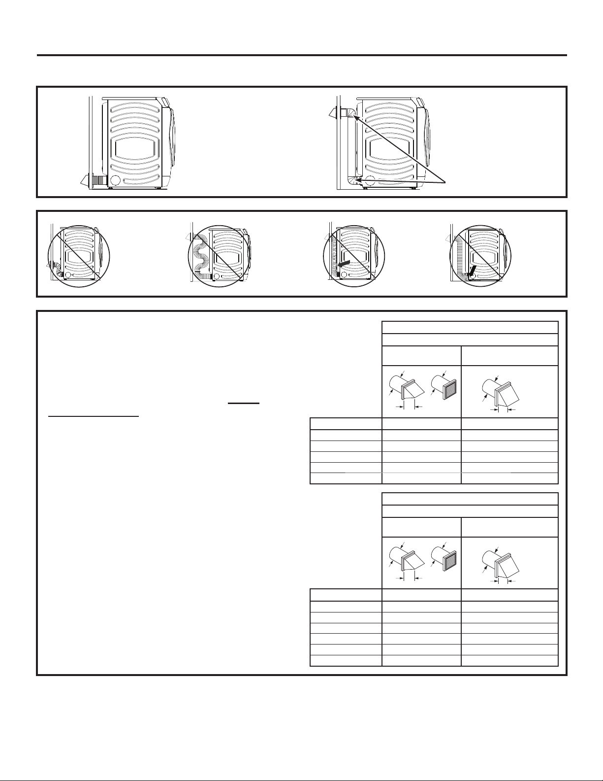
• DO cut duct as short
as possible and
install straight into
wall.
• DO NOT bend
or collapse
ducting.
Use elbows
if turns are
necessary.
• DO NOT use
excessive
exhaust
length. Cut
duct as short
as possible.
EXHAUST LENGTH
Using exhaust longer than specified length will:
• Increase the drying times and the energy cost.
• Reduce the dryer life.
• Accumulate lint, creating a potential fire hazard.
The correct exhaust installation is YOUR
RESPONSIBILITY.
Problems due to incorrect installation are not
covered by the warranty.
The MAXIMUM ALLOWABLE length of the exhaust
system depends upon the type of duct, number of turns,
the type of exhaust hood (wall cap) and all conditions
noted on the chart.
• Internal elbows added for side or bottom vent
conversions must be included in the total elbow count.
• Any elbow greater than 45° should be treated as a 90°
elbow; one elbow of 45° or less may be ignored.
• Two 45° elbows will be treated like one 90° elbow.
• For the side exhaust installations, add one 90° elbow to
the chart.
• For every additional 90° elbow, reduce the allowable
vent system length by 10 feet (3 m).
• When calculating the total vent system length, you
must add all the straight portions and elbows of the
system (including the transition duct).
• DO use elbows
when turns are
necessary.
Elbows
• DO NOT
set dryer
on duct
installations
4" DIA.
EXHAUST
LENGTH
FOR
NORMAL
• DO NOT
crush duct
against
the wall
4" DIA.
.
RECOMMENDED MAXIMUM LENGTH
Exhaust Hood Types
Recommended
4" DIA.
Use only for short run
VENT
MODELS
No. of 90° Elbows Rigid Metal Rigid Metal
0 90 Feet (27.4 m) 60 Feet (18.3 m)
1 60 Feet (18.3 m) 45 Feet (13.7 m)
2 45 Feet (13.7 m) 35 Feet (10.7 m)
3 35 Feet (10.7 m) 25 Feet (7.6 m)
4 25 Feet (7.6 m) 15 Feet (4.6 m)
EXHAUST
LENGTH
FOR
LONG
4"
RECOMMENDED MAXIMUM LENGTH
Exhaust Hood Types
Recommended
4" DIA.
4" DIA.
Use only for short run
installations
4" DIA.
2-1/2"
VENT
MODELS
No. of 90° Elbows Rigid Metal Rigid Metal
0 200 Feet (61 m) 175 Feet (53.3 m)
1 185 Feet (56.4 m) 165 Feet (50.3 m)
2 175 Feet (53.3 m) 155 Feet (47.2 m)
3 165 Feet (50.3 m) 145 Feet (44.2 m)
4 155 Feet (47.2 m) 135 Feet (41.1 m)
5 145 Feet (44.2 m) 125 Feet (38.1 m)
4"
2-1/2"
.
26 49-3000386 Rev 0
Page 14
Installation Instructions
EXHAUSTING THE DRYER (cont.)
EXHAUST SYSTEM CHECKLIST
HOOD OR WALL CAP
• Terminate in a manner to prevent back drafts or entry of
birds or other wildlife.
• Termination should present minimal resistance to
the exhaust airflow and should require little or no
maintenance to prevent clogging.
• Wall caps must be installed at least 12” (30.5 cm)
above ground level or any other obstruction with the
opening pointed down.
SEPARATION OF TURNS
• For best performance, separate all turns by at least
4 ft. (1.2 m) of straight duct, including distance
between last turn and dampened exhaust hood
(wall cap).
SEALING OF JOINTS
• All joints should be tight to avoid leaks. The male end
of each section of duct must point away from the dryer.
• Duct joints should be made air- and moisture-tight
by wrapping the overlapped joints with aluminum
foil tape.
• Do not assemble ductwork with any fasteners that
extend into the duct. These fasteners can accumulate
lint, creating a potential fire hazard.
• Horizontal runs should slope down towards the
outdoors 1/4” (6.4 mm) per foot.
• Provide an access for inspection and cleaning of
the exhaust system, especially at turns and joints.
Exhaust system shall be inspected and cleaned at
least once a year.
INSULATION
• Ductwork that runs through an unheated area or is
near air conditioning should be insulated to reduce
condensation and lint build-up.
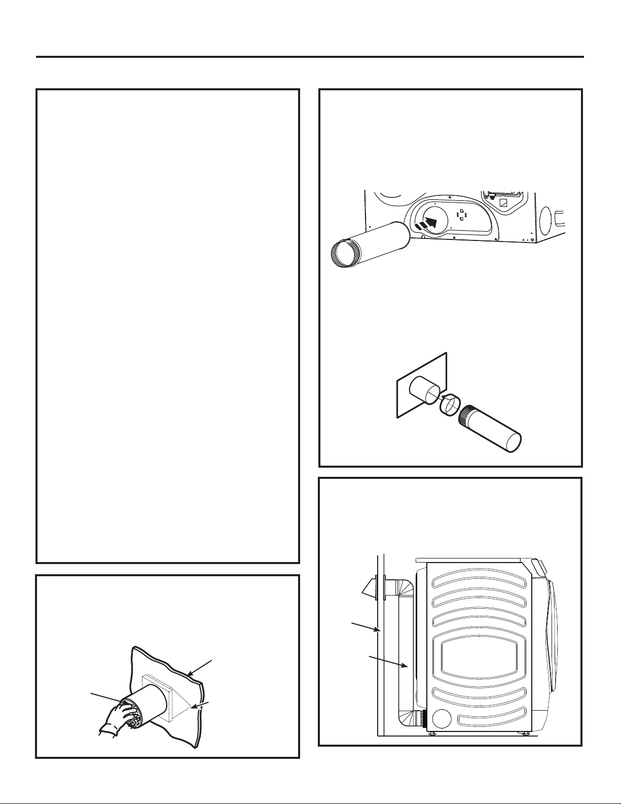
STANDARD REAR EXHAUST
We recommend that you install your dryer before
installing your washer. This will permit direct
access for easier exhaust connection.
Slide the end of the exhaust duct on the back of the
dryer and secure with aluminum foil tape or a hose
clamp.
Duct
NOTE: We strongly recommend using rigid metal
exhaust duct. However, if flexible ducting is used it
must be UL-Listed metal, not plastic.
• For straight line installation, connect the dryer exhaust
to the external exhaust hood using aluminum foil tape
or clamp.
Wall Side
Aluminum foil tape
Dryer
Side
RECOMMENDED CONFIGURATION
TO MINIMIZE EXHAUST BLOCKAGE
Using duct elbows will prevent duct kinking and
collapsing.
BEFORE YOU BEGIN
• Remove and discard existing plastic or metal foil
duct and replace with UL-listed duct.
• Remove any lint from the wall exhaust opening.
Wall
Internal
Duct
Opening
Check that exhaust
hood damper
opens and closes
freely.
49-3000386 Rev 0 27
Wall
Transition
Ducting
Page 15
Installation Instructions
EXHAUSTING THE DRYER (cont.)
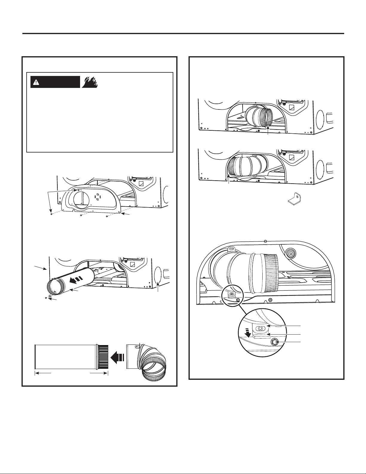
SIDE VENTING
WARNING
Disconnect dryer from electrical supply.
Wear gloves and arm guards.
Close the back opening with the access
panel included in kit GFA28DSVN.
Failure to do so may result in fire, electrical
shock or lacerations.
• Remove the 4 screws that secure the access panel
and save. Remove the access panel.
Remove
4 screws
and save
• Detach and remove the right or left side knockout
as desired. Remove the screw that secures the
dryer exhaust duct and save. Pull the exhaust duct
out of the dryer.
Right
knockout
- Fire Hazard
Access Panel
SIDE VENTING (cont.)
• Insert and connect the elbow/exhaust duct assembly
to the blower housing and orient the elbow for either
left or right venting.
Left Venting
Right Venting
• Locate the bracket from the kit.
• Remove the adhesive liner from the bottom of the
bracket and position it behind the elbow duct tab.
• Press down firmly to secure the bracket to the bottom
of the dryer.
Exhaust Duct
Remove screw and save
• Locate the 12-1/2” (31.5 cm) exhaust duct and
elbow duct from the kit and assemble together.
Apply aluminum foil tape around the joint to
eliminate leaks between ducts.
12-1/2" (31.5 cm)
Left Knockout
Elbow Duct Tab
Bracket
Saved Screw
• Using one of the screws from earlier, secure the
elbow duct tab to the bracket.
28 49-3000386 Rev 0
Page 16
Installation Instructions
EXHAUSTING THE DRYER (cont.)
SIDE VENTING (cont.)
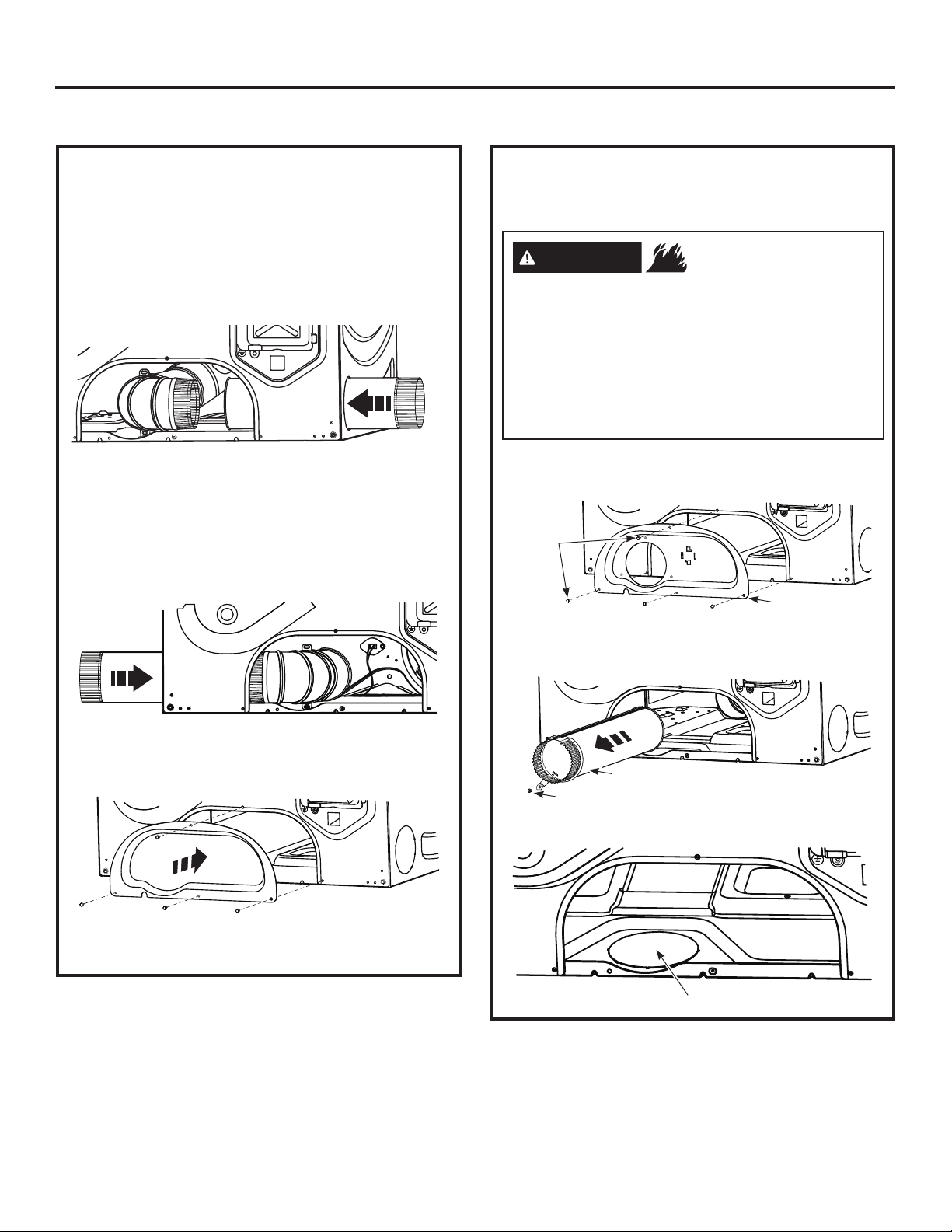
For LEFT venting:
• Locate the 15-1/2” (39.4 cm) exhaust duct from the kit.
• Insert exhaust duct through knockout opening on
the LEFT side of dryer.
• Assemble exhaust duct to elbow duct.
• Wrap the joint with aluminum foil tape to avoid air
leaks.
Left
Venting
For RIGHT venting:
• Locate the 9-1/2” (24.2 cm) exhaust duct from the kit.
• Insert exhaust duct through knockout opening on
the RIGHT side of dryer.
• Assemble exhaust duct to elbow duct.
• Wrap the joint with aluminum foil tape to avoid air
leaks.
Right
Venting
BOTTOM VENTING
Dryer Exhaust to the bottom of cabinet for Gas
and Electric models WITHOUT Built-In Pedestal™.
WARNING
Disconnect dryer from electrical supply.
Wear gloves and arm guards.
Close the back opening with the access
panel included in kit GFA28DSVN.
Failure to do so may result in fire, electrical
shock or lacerations.
• Remove the 4 screws that secure the access panel
and save. Remove the access panel.
Remove
4 screws
and save
• Remove the screw that secures the dryer exhaust
duct and save. Pull the exhaust duct out of the dryer.
- Fire Hazard
Access Panel
• Install the new access panel from the kit.
• Secure access panel with 4 screws saved from
earlier.
NEVER LEAVE THE BACK OPENING WITHOUT
THE ACCESS PANEL.
Exhaust Duct
Remove screw and save
• Detach and remove the bottom knockout.
Bottom Knockout
49-3000386 Rev 0 29
Page 17
Installation Instructions
EXHAUSTING THE DRYER (cont.)
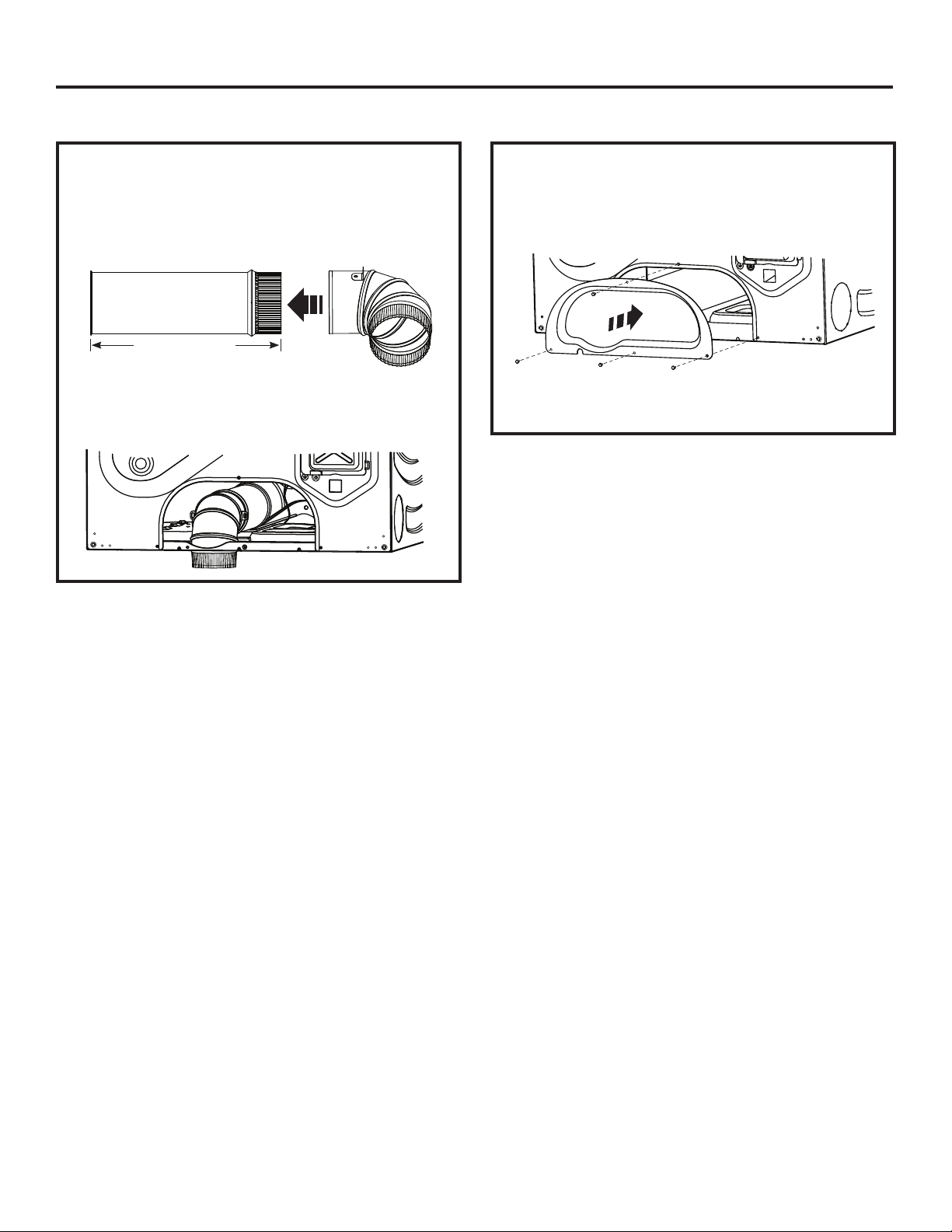
BOTTOM VENTING (cont.) BOTTOM VENTING (cont.)
• Locate the 12-1/2” (31.5 cm) exhaust duct and
elbow duct from the kit and assemble together.
Apply aluminum foil tape around the joint to eliminate
leaks between ducts.
12-1/2” (31.5 cm)
• Install the new access panel from the kit.
• Secure access panel with 4 screws saved from
earlier.
• Insert and connect the elbow/exhaust duct
assembly to the blower housing and insert the
elbow through the bottom knockout.
NEVER LEAVE THE BACK OPENING WITHOUT
THE ACCESS PANEL.
30 49-3000386 Rev 0
Page 18
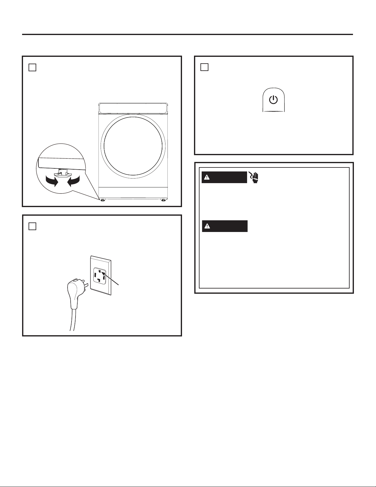
FINAL SETUP
Installation Instructions
1
LEVEL THE DRYER
Stand the dryer upright near the final location and
adjust the four leveling legs at the corners to ensure
that the dryer is level from side to side and front to
rear.
Lower
2
PLUG DRYER IN
NOTE: Stacking installations may require a power
cord up to 6 feet (1.8 m) in length.
Raise
Ensure proper
ground exists
before use.
3
DRYER START-UP
Press the Power pad.
NOTE: If the dryer has been exposed to temperatures
below freezing for an extended period of time, allow it to
warm up before pressing Power. Otherwise, the display
will not come on.
The dryer is now ready for use.
WARNING
Disconnect power supply before servicing.
Replace all parts and panels before operating.
Failure to do so can result in death or electrical
shock.
WARNING
Certain internal parts are intentionally not grounded
and may present a risk of electric shock only during
servicing.
Service personnel – DO NOT contact the following
parts while the appliance is energized: water
valve, door switch, electronic board, igniter,
thermostats, flame detector.
- Electrical Shock Hazard
- Shock Hazard
49-3000386 Rev 0 31
Page 19
Installation Instructions
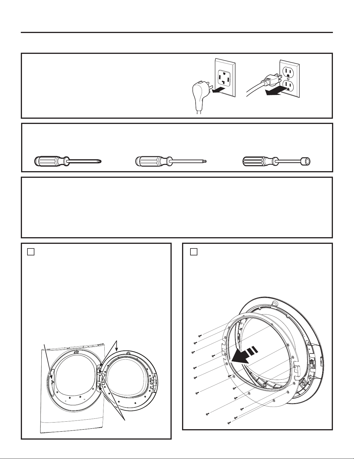
REVERSING THE DOOR SWING (Optional)
BEFORE YOU START
Unplug the dryer from its electrical outlet.
TOOLS YOU WILL NEED
Phillips-head screwdriver T-25 torx driver 1/4” (6.4 mm) nut driver
IMPORTANT NOTES
• Handle parts carefully to avoid scratching paint.
• Provide a non-scratching work surface for the door.
• Set screws down by their related parts to avoid using
them in the wrong places.
• Once you begin, do not move the cabinet until
door-swing reversal is completed.
• These instructions are for changing the hinges from the
right side to the left side—if you ever want to switch them
back to the right side, follow these same instructions and
reverse all references to the left and right.
1
REMOVE THE STRIKE PLATE
AND DOOR ASSEMBLY
• Open the dryer door.
• Remove the two screws from the strike plate using
a T-25 torx driver.
• Remove the strike plate and set it aside.
• While supporting the door, remove the two screws
from the hinge in the dryer face using a 1/4” (6.4 mm)
nut driver.
• Lift the door assembly to remove it from the dryer
face and set it aside on a protective surface.
Remove Strike
Plate and Screws
Hinge and Door
Assembly
2
REMOVE THE INNER DOOR
• Remove the 14 screws from the inner door frame
using a Phillips-head screwdriver and set them aside.
• Remove the inner door frame from the outer door.
NOTE: Do not remove the gasket from the inner door
frame.
Hold the Door and
Remove Hinge Screws
from the Dryer
32 49-3000386 Rev 0
Page 20
Installation Instructions
REVERSING THE DOOR SWING (Optional)
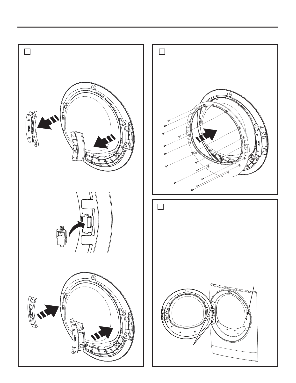
3
REMOVE, ROTATE AND REPLACE
THE HANDLE AND HINGE INTO
THE OPPOSITE SIDES
• Lift the handle and the hinge out of the door pockets.
NOTE: Make sure the latch remains seated inside the
handle. If it moves or falls out, seat it back into place.
4
REPLACE THE INNER DOOR
• Replace the inner door frame into the outer door.
Replace the 14 screws into the inner door, using a
•
Phillips-head screwdriver, securing it to the outer door.
NOTE: Make sure the gasket is properly seated on
the inner door frame when replaced.
• Rotate the handle and hinge, and replace them
back into the pockets on the opposite sides.
5
REPLACE THE STRIKE PLATE
AND DOOR ASSEMBLY
• On the opposite side from where removed, replace
the strike plate with its two screws using a T-25 torx
driver.
• Lift the door assembly into place and secure it onto
the dryer face with its two screws using a 1/4” (6.4 mm)
nut driver.
• Close the dryer door.
NOTE: Make sure the door opens and closes
correctly. If not, repeat all steps making sure the
gasket, all parts, and screws are securely seated.
Replace Strike
Plate and Screws
Hold the Door and
Replace Hinge Screws
into the Dryer
49-3000386 Rev 0 33
Page 21
Installation Instructions
STACKING THE WASHER AND DRYER (if desired)
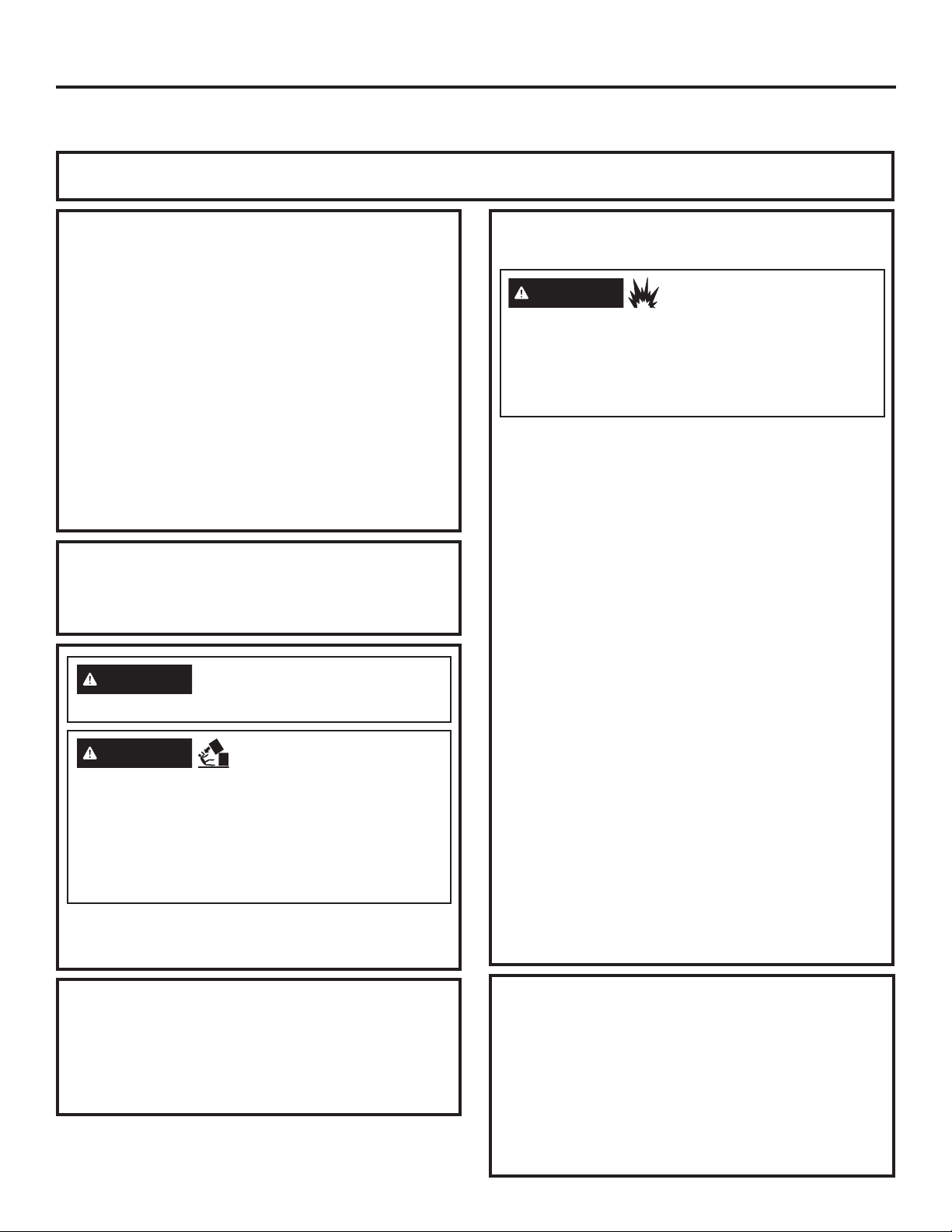
If you are planning to stack the washer and dryer, order Stacking Kit GFA28KITN to be used for this dryer. Kit sold separately.
If you have any questions, call GE Appliances at 800.432.2737 or visit our Website at: GEAppliances.com
In Canada, call 800.561.3344 or visit www.GEAppliances.ca
BEFORE YOU BEGIN
Read these instructions completely and carefully.
• IMPORTANT – Save these instructions for
local electrical inspector’s use.
• IMPORTANT – Observe all governing
codes and ordinances.
• Note to Installer – Be sure to leave these
instructions with the Consumer.
• Note to Consumer – Keep these instructions for
future reference.
• Installation must be performed by a qualified
installer.
• Proper installation is the responsibility of the installer.
Stack dryer only on washer. Do not stack washer on
dryer, washer on washer or dryer on dryer.
Do not modify this installation kit. Any modification will
void the product Warranty.
WARNING
result in serious injury or death.
WARNING
• Use two or more people to install dryer.
• Avoid tipping and rupture of utility services.
• Dryer must be securely attached to the washer.
• DO NOT place the washer on top of the dryer.
Failure to do so may result in serious injury,
death, or property damage.
Mobile Home or Manufactured Home Installation –
Stacking of a gas dryer is not permitted in a mobile
home or manufactured home.
Disconnect power before
installing. Failure to do so could
- Excessive Weight
Hazard
REQUIREMENTS FOR ALCOVE OR
CLOSET INSTALLATION
WARNING
Keep flammable materials and vapors, such as
gasoline,
away from dryer.
Place dryer at least 18” (46 cm) above the floor
for a garage installation.
Failure to do so can result in death, explosion, or fire.
• The dryer MUST be vented to the outdoors.
• Minimum clearance between dryer cabinet and
adjacent walls or other surfaces is:
0” (0 cm) either side*
0” (0 cm) front
0” (0 cm) rear
0” (0 cm) top
• The rear of the dryer should face a wall.
• Consideration must be given to provide adequate
clearance for installation and service.
• Closet doors must be louvered or otherwise ventilated
and have at least 60 square inches (387 cm2) of open
area. If the closet contains both a washer and a dryer,
doors must contain a minimum of 120 square inches
(774 cm2) of open area.
NOTE: WHEN THE EXHAUST DUCT IS LOCATED AT
THE REAR OF THE DRYER, THE CONFIGURATION
OF THE DUCTING MAY REQUIRE GREATER
CLEARANCE.
Gas Dryers Only:
• No other fuel burning appliance shall be installed in
the same closet as a gas dryer.
• The dryer must be disconnected from the gas
supply piping during pressure testing at pressures
greater than 1/2 psi (3.5 kPa).
• A 1/8” (3.2 mm) NPT minimum plugged tapping,
accessible for test gauge connection, must be
installed immediately upstream of the gas supply
connection to the dryer.
- Explosion Hazard
INSTALLATION PREPARATION
Remove the packaging.
Flatten the product carton to use as a pad to lay
the dryer down on its back or side. Continue using
the carton to protect the finished floor in front of the
installation location.
For improved performance, a 1/2” (12.7 mm) clearance is suggested on
*
either side.
MINIMUM CLEARANCE OTHER
THAN ALCOVE OR CLOSET
INSTALLATION
Minimum clearance to combustible surfaces and for
air opening are: 0” (0 cm) both sides
and 0” (0 cm) top.
The rear of the dryer should face a wall.
Consideration must be given to provide adequate
clearance for installation and service.
*, 0” (0 cm) rear
34 49-3000386 Rev 0
Page 22
Installation Instructions
Ŷ
Ŷ
Ŷ
Ŷ
Ŷ
Ŷ
Ŷ
Ŷ
Ŷ
STACKING THE WASHER AND DRYER
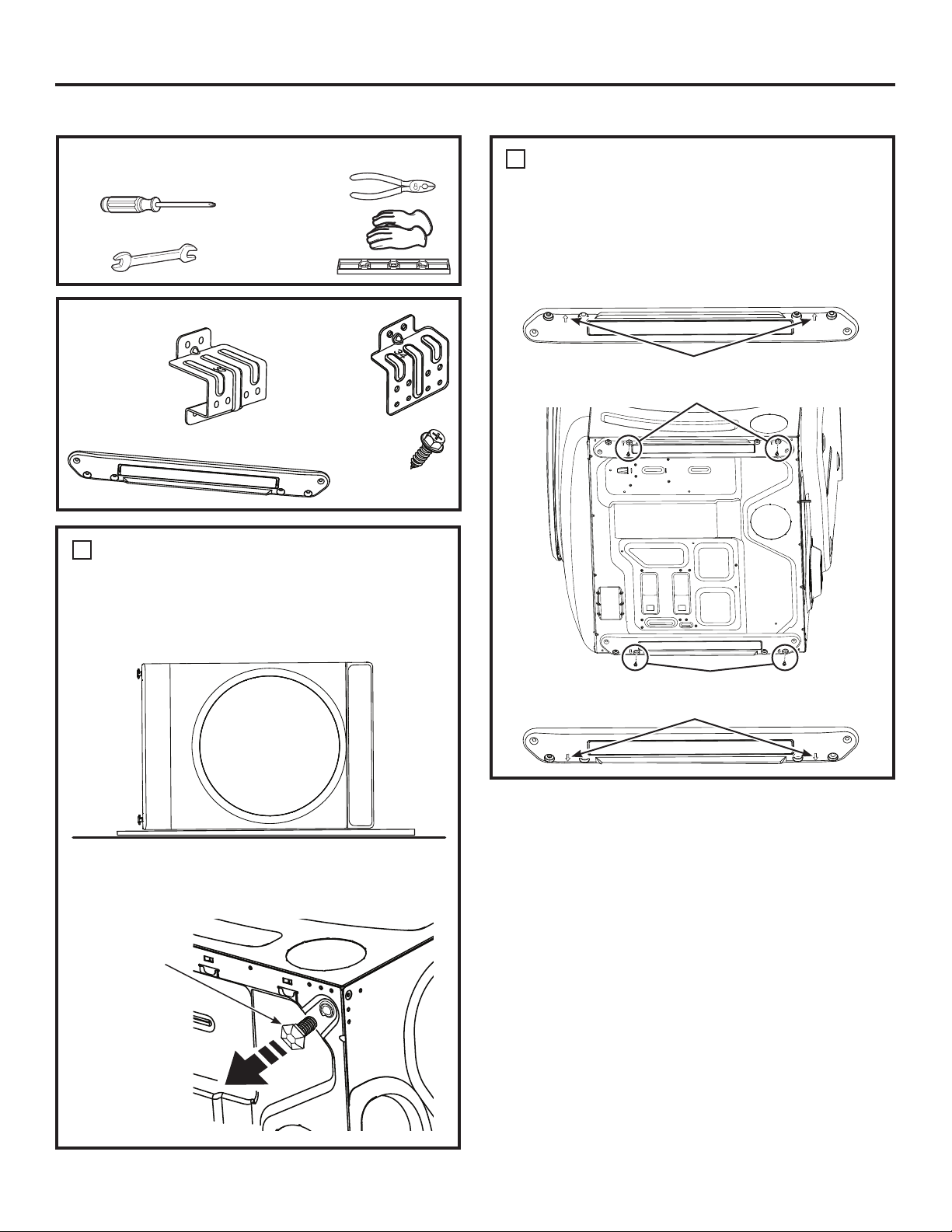
TOOLS YOU WILL NEED
Ŷ
Phillips screwdriver
Ŷ
Open-ended wrench
Ŷ
Pliers
Ŷ
Gloves
Ŷ
Level
CONTENTS
Ŷ
Bracket 32
(2)
Ŷ
Spacer (2)
1
REMOVE THE DRYER LEVELING
Ŷ
Bracket 34
(2)
Ŷ
#8 1/2" (12.7 mm)
Screws (16)
LEGS
A. Carefully lay the dryer on its back or side. Use the
packing material so you don’t scratch the finish on
the dryer.
2
INSTALL SPACERS TO THE
DRYER BOTTOM
Locate a spacer on the bottom side with its holes over
the leveling leg holes. Attach spacer using 2 screws.
Attach the second spacer on the other bottom side
using 2 screws. NOTE: The arrows on the spacers
should point to the outside.
Make sure the arrows on the spacer point to the outside.
Attach spacer using 2 screws
Front Back
(Optional Kit GFA28KITN)
B. Use an open-end wrench or pliers to remove the
dryer leveling legs. NOTE: Retain the leveling legs
for future use.
Back out and
remove all 4
leveling legs
Attach spacer using 2 screws
Make sure the arrows on the spacer point to the outside.
49-3000386 Rev 0 35
Page 23
Installation Instructions
STACKING THE WASHER AND DRYER
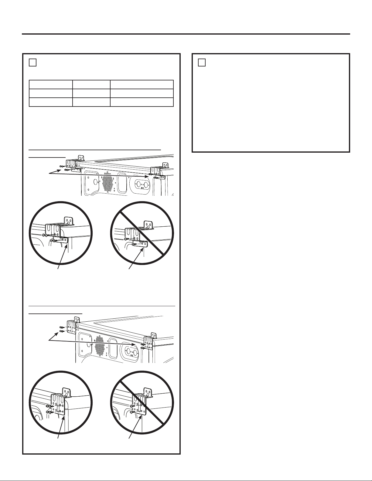
3
INSTALL THE APPROPRIATE
BRACKETS TO THE WASHER
Washer Depth Dryer Depth Bracket Number
32" (81.3 cm) 32" (81.3 cm) 32
34" (86.4 cm) 32" (81.3 cm) 34
Select the appropriate brackets for your model sizes.
Using the outside holes in the bracket, attach it to the
top left corner of the washer back using 4 screws.
Repeat on the top right corner of the washer back.
o
N
32 Brackets for 32" (81.3 cm) Washer & Dryer
Combinations:
Attach
brackets to
washer using
4 screws on
each side
4
PREPARE THE WASHER AND
DRYER
A. Place the washer in the approximate final
installation location.
B. Make sure the washer is level. Refer to the washer
Installation Instructions for details.
C. Upright the dryer.
D. Reverse the washer and dryer door swings, if
desired, before stacking the dryer on the washer.
See the washer and dryer Installation Instructions
for details.
(Optional Kit GFA28KITN)
Install brackets flush at
washers edges
Do not install brackets
overhanging washers edges
OR
No 34 Brackets for 34" (86.4 cm) Washer & 32" (81.3 cm)
Dryer Combinations:
Attach
brackets to
washer using
4 screws on
each side
Install brackets flush at
washers edges
Do not install brackets
overhanging washers edges
36 49-3000386 Rev 0
Page 24
Installation Instructions
STACKING THE WASHER AND DRYER
5
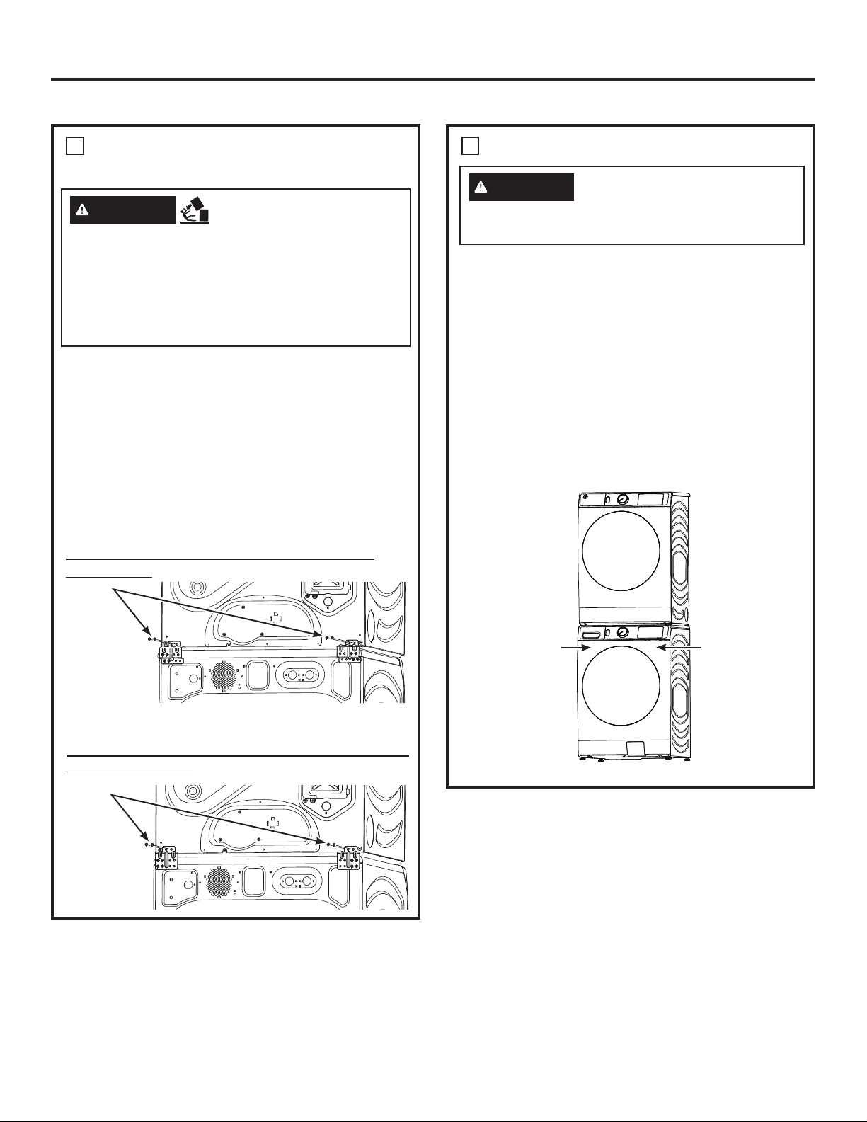
INSTALL THE DRYER AND THE
BRACKET ON THE WASHER
WARNING
• Use two or more people to install dryer.
• Avoid tipping and rupture of utility services.
• Dryer must be securely attached to the washer.
• DO NOT place the washer on top of the dryer.
Failure to do so may result in serious injury,
death, or property damage.
A. Lift the dryer onto the top of the washer.
Be sure to lift the dryer high enough to clear the
washer control panel.
Be careful not to scratch the top of the washer with
the spacers. Protect the washer control panel with
cardboard or other protection.
B. Align the holes in the back of the dryer with the
holes in the bracket sticking up from the washer.
Attach both brackets to the dryer with 2 screws on
each side.
o
N
32 Brackets for 32" (81.3 cm) Washer & Dryer
Combinations:
Attach
brackets
to dryer
using 2
screws on
each side
- Excessive Weight
Hazard
6
FINALIZE THE INSTALLATION
CAUTION
Do not push on the dryer once
installed to top of the washer.
Pushing on the dryer may result in pinched
fingers.
A. Refer to the washer Installation Instructions to
complete the washer installation.
B. Refer to the dryer Installation Instructions to
complete the dryer installation.
C. Carefully slide or walk the stacked washer and
dryer into place. Use felt pads or other sliding
device to assist moving and to protect flooring.
D. Verify the units are level. Make adjustments to
the washer feet if necessary to level. It is always
best to set the washer feet to the minimum height
necessary to level the washer and dryer properly.
Place
hands
here
(Optional Kit GFA28KITN)
Dryer
Place
hands
here
OR
No 34 Brackets for 34" (86.4 cm) Washer & 32" (81.3 cm)
Dryer Combinations:
Attach
brackets
to dryer
using 2
screws on
each side
49-3000386 Rev 0 37
Washer
Page 25
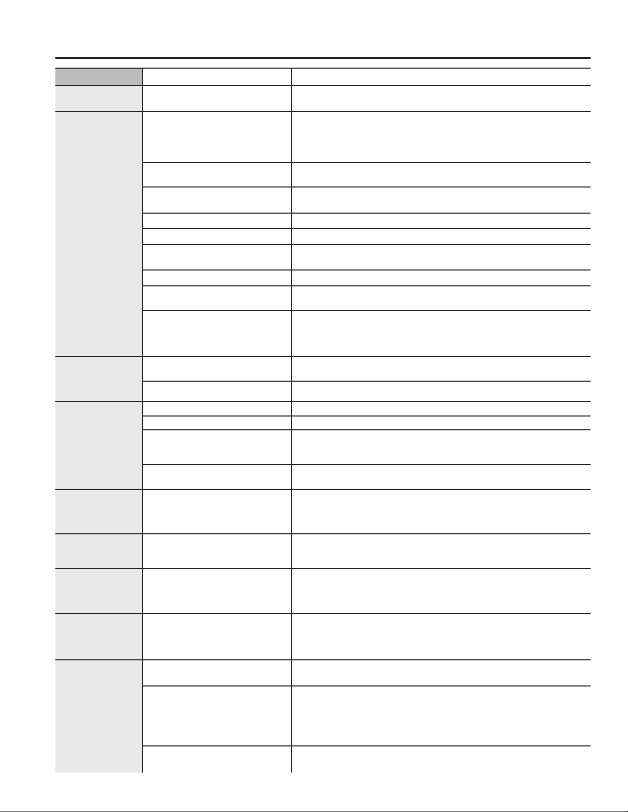
Troubleshooting Tips... Before you call for service
Problem Possible Cause What To Do
Dryer shakes or
makes noise
Clothes take
too long to dry
TROUBLESHOOTING TIPS
The Dry dryness
level was
chosen but load
is still damp
Dryer doesn’t
start
No numbers
displayed
during cycle,
only lights
Time Remaining
jumped to a
lower number
Cannot make a
selection and
the dryer beeps
twice
Dryer is running
but 00 is
displayed in
Time Remaining
“Check Vent”
light is on
Some shaking/noise is normal.
Dryer may be sitting unevenly.
Improper or obstructed
ducting
Improper sorting Separate heavy items from lightweight items (generally, a
Large loads of heavy fabrics
(like beach towels)
Controls improperly set Match control settings to the load you are drying.
Lint filter is full Clean lint filter before every load.
Blown fuses or tripped
circuit breaker
Overloading/combining loads Do not put more than one washer load in the dryer at a time.
Underloading If you are drying only one or two items, add a few items to ensure
ecoDry is enabled The ecoDry feature is designed to operate your dryer in the
Load consists of a mixture of
heavy and light fabrics
Exhaust system is blocked Inspect and clean exhaust system.
Control panel is “asleep” This is normal. Press Power to activate the control panel.
Dryer is unplugged Make sure the dryer plug is pushed completely into the outlet.
Fuse is blown/circuit breaker
is tripped
Dryer was accidentally paused
when starting Delay Dry
Dryer is continuously
monitoring the amount of
moisture in the clothes
The estimated time may
change when a smaller load
than usual is drying
The dryness Level, Temp or
option that you are trying to
select is incompatible with
the chosen dry cycle
The Wrinkle Care option
was chosen
Lint filter is full Clean lint filter, dry a load on an automatic cycle and verify that
Improper or obstructed
ducting
Exhaust system is blocked Inspect and clean the exhaust system.
Move dryer to an even floor space, or adjust leveling legs as
necessary until even.
Check the Installation Instructions to make sure the dryer
venting is correct.
Make sure ducting is clean, free of kinks and unobstructed.
Check to see if outside wall damper operates easily.
well-sorted washer load is a well-sorted dryer load).
Large, heavy fabrics contain more moisture and take longer to dry.
Separate large, heavy fabrics into smaller loads to speed drying time.
Replace fuses or reset circuit breakers. NOTE: Some electric
dryers use 2 fuses/breakers, make sure both are operating.
proper tumbling.
most energy efficient mode, which is not always the fastest
mode. In some instances, dry times may be extended to
reduce overall energy usage for the cycle.
When combining heavy and light fabrics in a load, choose
More Dry.
Check the building’s fuse/circuit breaker box and replace fuse
or reset breaker. NOTE: Some electric dryers use two fuses/
breakers, make sure both are operating.
If the light on the Start/Pause pad is flashing, the dryer is paused.
Press Start/Pause to restart the countdown.
This is normal. When the dryer senses a low level of moisture in
the load, the dryer will display the dry time remaining.
This is normal.
This is normal.
This is normal. During extended tumbling, the time remaining is
not displayed. The extended tumbling option lasts approximately
60 minutes.
light turns off.
Check the Installation Instructions to make sure the dryer venting
is correct.
Make sure ducting is clean, free of kinks and unobstructed. Check
to see if outside wall damper operates easily.
Dry a load on an automatic cycle and verify that light turns off.
Dry a load on an automatic cycle and verify that light turns off.
38 49-3000386 Rev 0
Page 26
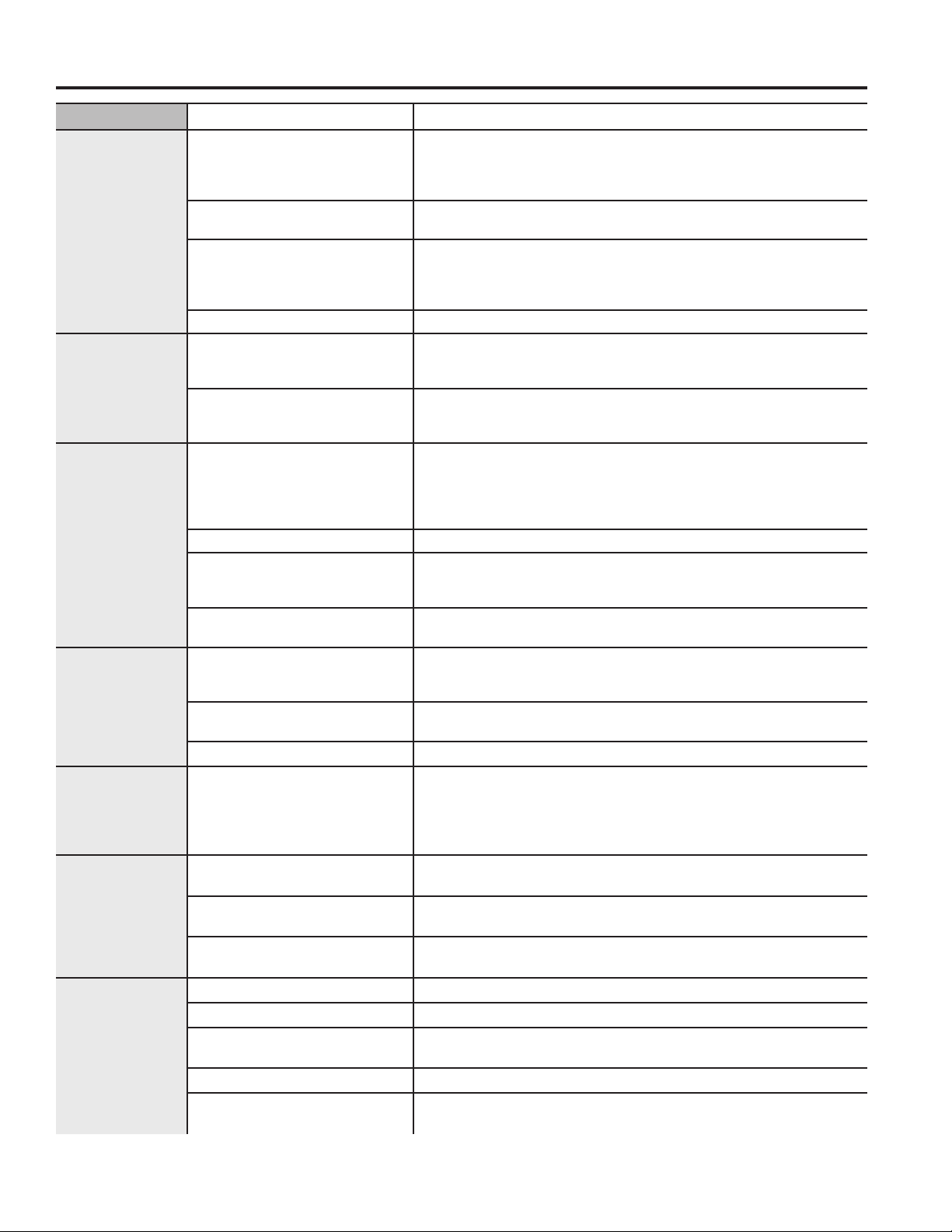
Troubleshooting Tips... Before you call for service
Problem Possible Causes What To Do
Dryer doesn’t
heat
Inconsistent
drying times
Clothes are still
wet and dryer
shut off after a
short time
Clothes are
wrinkled
Clothes shrink Some fabrics will naturally
Greasy spots
on clothes
Lint on clothes Lint filter is full Clean lint screen before each load.
Fuse is blown/circuit breaker
is tripped; the dryer may
tumble but not heat
Gas service is off (gas
models only)
LP gas supply tank is empty
or there has been a utility
interruption of natural gas
(gas models only)
No heat temperature selected Select another heat setting
Type of heat Drying time will vary according to the type of heat used. If
Type of load and drying
conditions
The door was opened
mid-cycle. The load was then
removed from the dryer and
a new load put in without
selecting a new cycle
Small load When drying 3 items or less, choose QUICK DRY or TIMED DRY.
Load was already dry except
for collars and waistbands
Dryer is not level Move dryer to an even floor space or adjust leveling legs as
Overdrying Select a shorter drying time.
Letting items sit in dryer after
cycle ends
Overloading Separate large loads into smaller ones.
shrink when washed. Others
can be safely washed, but
will shrink in the dryer.
Improper use of fabric
softener
Drying dirty items with clean
ones
Clothes were not completely
clean
Improper sorting Sort lint producers (like chenille) from lint collectors (like corduroy).
Static electricity can attract
lint
Overloading Separate large loads into smaller ones.
Paper, tissue, etc., left in
pockets
Check the building’s fuse/circuit breaker box and replace both
fuses or reset both breakers. Your dryer may tumble if only one
fuse is blown or one breaker tripped. NOTE: Some electric
dryers use 2 fuses/breakers, make sure both are operating.
Make sure gas shutoff at dryer and main shutoff are fully open.
Refill or replace tank. Dryer should heat when utility service is
restored.
you recently changed from an electric to a gas (natural or LP)
dryer, or vice versa, the drying time could be different.
The load size, types of fabric, wetness of clothes and the
length and condition of the exhaust system will affect drying
times.
A dry cycle must be re-selected each time a new load is put in.
Choose
waistbands. In the future, when drying a load with collars and
waistbands, choose More Dry.
necessary until even.
Remove items while they still hold a slight amount of moisture.
Select a Less Dry or Damp setting.
Remove items when cycle ends and fold or hang immediately, or
use the Wrinkle Care option.
To avoid shrinkage, follow garment care labels exactly.
Some items may be pressed back into shape after drying.
If you are concerned about shrinkage in a particular
item, do not machine wash or tumble dry it.
Follow directions on fabric softener package.
Use your dryer to dry only clean items. Dirty items can stain clean
items and the dryer.
Sometimes stains which cannot be seen when the clothes are wet
appear after drying. Use proper washing procedures before drying.
See suggestions in this section under Static occurs.
Empty all pockets before laundering clothes.
QUICK DRY or TIMED DRY to dry damp collars and
TROUBLESHOOTING TIPS
49-3000386 Rev 0 39
Page 27
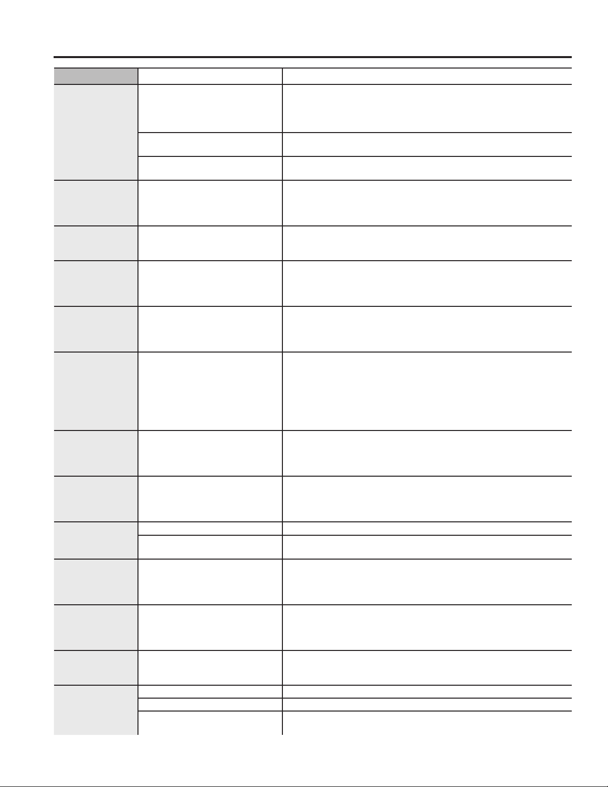
Troubleshooting Tips... Before you call for service
Problem Possible Causes What To Do
Static occurs No fabric softener was used Try a fabric softener.
®
Fabric Conditioner Dryer Sheets have been approved for
Overdrying Try a fabric softener.
Synthetics, permanent press
and blends can cause static
Collars and
waistbands still
wet at end of
cycle
Slight variation
in metallic color
Dryer continues
to tumble after
TROUBLESHOOTING TIPS
display says
Complete
Door is too
foggy to see
clothes during a
steam cycle
Water seen on
inside of door
and top of lint
filter when
opening door
after steam
cycle
Small areas
on clothes are
damp after
steam cycle
Small amount of
water on floor in
front of dryer
Water on floor in
back of dryer
Water drips
from door when
opened after a
Steam Cycle
Cannot see
steam at
beginning of
cycle
Cannot see
steam during
cycle
Garments still
wrinkled after
steam cycle
The dryness monitor senses
that the body of the clothes
is dry
This is normal Due to the metallic properties of paint used for this unique product,
Wrinkle Care was selected Ensure Wrinkle Care option is not selected. For the Steam
Steam condenses on inner
door
Steam condenses on these
surfaces
Steam condenses on inner
drum
Inadequate load size for
steam cycle selected, excess
steam condenses inside
cabinet and leaks out
Loose water hose connection Tighten connection.
Hose missing rubber washer
at connection with valve
Steam condenses on inner
door
Steam released at different
times in the cycle
The steam nozzle might be
clogged with debris from your
water supply
Too many garments Load fewer garments; manually increase time.
Lint filter not clean Clean lint filter
Load is children/infant
garments
Bounce
use in all GE Appliances dryers when used in accordance with the
manufacturer’s instructions.
Adjust setting to Less Dry or Damp.
Try a fabric softener.
Choose QUICK DRY or TIMED DRY to dry damp collars and
waistbands. In the future, when drying a load with collars and
waistbands, choose More Dry.
slight variations of color may occur due to viewing angles and
lighting conditions.
Refresh cycle, Wrinkle Care will automatically be turned on
and cannot be turned off.
This is normal.
This is normal.
If using the STEAM Dewrinkle cycle, manually reduce the cycle
time. If using the STEAM Refresh cycle, add more garments to
the load.
If using the STEAM Dewrinkle cycle, manually reduce the cycle
time. If using the STEAM Refresh cycle, add more garments to
the load.
Install rubber washer provided with hose.
This is normal.
This is normal.
Call GE Appliances at 877.959.8688 to order nozzle
replacement kit WE25M71 or to request a technician to replace
this for you.
Use the Steam Refresh cycle
40 49-3000386 Rev 0
Page 28
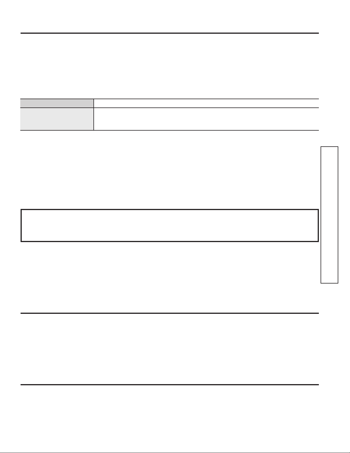
GE Appliances Dryer Limited Warranty
GEAppliances.com
All warranty service is provided by our Factory Service Centers, or an authorized Customer Care® technician. To schedule
service online, visit us at GEAppliances.com/service, or call GE Appliances at 800.GE.CARES (800.432.2737). Please
have your serial number and your model number available when calling for service.
Servicing your appliance may require the use of the onboard data port for diagnostics. This gives a GE Appliances factory
service technician the ability to quickly diagnose any issues with your appliance and helps GE Appliances improve its
products by providing GE Appliances with information on your appliance. If you do not want your appliance data to be
sent to GE Appliances, please advise your technician not to submit the data to GE Appliances at the time of service.
For the period of: We will replace:
One year
From the date of the
original purchase
What is not covered:
Ŷ
Service trips to your home to teach you how to use
the product.
Ŷ
Improper installation, delivery or maintenance.
Ŷ
Failure of the product if it is abused, misused, or used for
other than the intended purpose or used commercially.
Ŷ
Replacement of house fuses or resetting of circuit
breakers.
Ŷ
Products which are not defective or broken, or which
are working as described in the Owner’s Manual.
Any part of the dryer which fails due to a defect in materials or workmanship. During
this limited one-year warranty, we will also provide, free of charge, all labor and
related service to replace the defective part.
Ŷ 'DPDJHWRWKHSURGXFWFDXVHGE\DFFLGHQWILUH
floods or acts of God.
Ŷ ,QFLGHQWDORUFRQVHTXHQWLDOGDPDJHFDXVHGE\
possible defects with this appliance.
Ŷ 'HIHFWVRUGDPDJHGXHWRRSHUDWLRQLQIUHH]LQJ
temperatures.
Ŷ 'DPDJHFDXVHGDIWHUGHOLYHU\
Ŷ 3URGXFWQRWDFFHVVLEOHWRSURYLGHUHTXLUHGVHUYLFH
LIMITED WARRANTY
Staple your receipt here. Proof of the original purchase
date is needed to obtain service under the warranty.
EXCLUSION OF IMPLIED WARRANTIES
Your sole and exclusive remedy is product repair as provided in this Limited Warranty. Any implied warranties,
including the implied warranties of merchantability or fitness for a particular purpose, are limited to one year or the
shortest period allowed by law.
In the United States:
This limited warranty is extended to the original purchaser and any succeeding owner for products purchased for home use
within the USA. If the product is located in an area where service by a GE Appliances Authorized Servicer is not available,
you may be responsible for a trip charge or you may be required to bring the product to an Authorized GE Appliances
Service location for service. In Alaska, the limited warranty excludes the cost of shipping or service calls to your home.
Some states do not allow the exclusion or limitation of incidental or consequential damages. This limited warranty
gives you specific legal rights, and you may also have other rights which vary from state to state. To know what your
legal rights are, consult your local or state consumer affairs office or your state’s Attorney General.
Warrantor: GE Appliances, a Haier Company, Louisville, KY 40225
In Canada:
This limited warranty is extended to the original purchaser and any succeeding owner for products purchased in Canada
for home use within Canada. If the product is located in an area where service by a GE Appliances Authorized Servicer is
not available, you may be responsible for a trip charge or you may be required to bring the product to an Authorized
GE Appliances Service location.
Some provinces do not allow the exclusion or limitation of incidental or consequential damages. This limited warranty
gives you specific legal rights, and you may also have other rights which vary from province to province. To know what
your legal rights are, consult your local or provincial consumer affairs office.
Warrantor: MC Commercial Inc., Burlington, ON, L7R 5B6
Extended Warranties: Purchase a GE Appliances extended warranty and learn about special discounts that are
available while your warranty is still in effect. You can purchase it online anytime at
GEAppliances.com/extended-warranty
or call 800.626.2224 during normal business hours. GE Appliances Service will still be there after your warranty expires.
49-3000386 Rev 0 41
Page 29
Consumer Support
GE Appliances Website
Have a question or need assistance with your appliance? Try the GE Appliances Website 24 hours a day, any day
of the year! You can also shop for more great GE Appliances products and take advantage of all our on-line support
services designed for your convenience. In the US: GEAppliances.com
In Canada: GEAppliances.ca
Register Your Appliance
Register your new appliance on-line at your convenience! Timely product registration will allow for enhanced
communication and prompt service under the terms of your warranty, should the need arise. You may also mail in
the pre-printed registration card included in the packing material. In the US: GEAppliances.com/register
In Canada: GEAppliances.ca/after-sales-support
CONSUMER SUPPORT
Schedule Service
Expert GE Appliances repair service is only one step away from your door. Get on-line and schedule your service at
your convenience any day of the year. In the US: GEAppliances.com/service or call 800.432.2737 during normal
business hours.
In Canada: GEAppliances.ca/after-sales-support or call 800.561.3344.
Extended Warranties
Purchase a GE Appliances extended warranty and learn about special discounts that are available while your
warranty is still in effect. You can purchase it on-line anytime. GE Appliances Services will still be there after your
warranty expires. In the US: GEAppliances.com/extended-warranty or call 800.626.2224 during normal business
hours.
In Canada: GEAppliances.ca/purchase-extended-warranty or call 866.277.9842.
Remote Connectivity
For assistance with wireless network connectivity (for models with remote enable), in the US visit our website at
GEAppliances.com/connect or call 800.220.6899.
In Canada: GEAppliances.ca/connected-appliances or call 800.220.6899
Parts and Accessories
Individuals qualified to service their own appliances can have parts or accessories sent directly to their homes
(VISA, MasterCard and Discover cards are accepted). Order on-line today 24 hours every day.
In the US: GEApplianceparts.com or by phone at 877.959.8688 during normal business hours.
In Canada: GEAppliances.ca/parts-filters-accessories or call 800.661.1616.
Instructions contained in this manual cover procedures to be performed by any user. Other servicing
generally should be referred to qualified service personnel. Caution must be exercised, since improper
servicing may cause unsafe operation.
Contact Us
If you are not satisfied with the service you receive from GE Appliances, contact us on our Website with all the
details including your phone number, or write to:
In the US: General Manager, Customer Relations | GE Appliances, Appliance Park | Louisville, KY 40225
GEAppliances.com/contact or call 800.626.2000
In Canada: Director, Customer Relations | MC Commercial Inc. | Suite 300, 5420 North Service Road | Burlington, ON L7L 6C7
GEAppliances.ca/contact-us or call 877.994.5366
Printed in the United States
42 49-3000386 Rev 0
 Loading...