

GE PDWT502VII User Manual
PDWT502VII
GE Profile™ Series Dishwasher with SmartDispense™ Technology
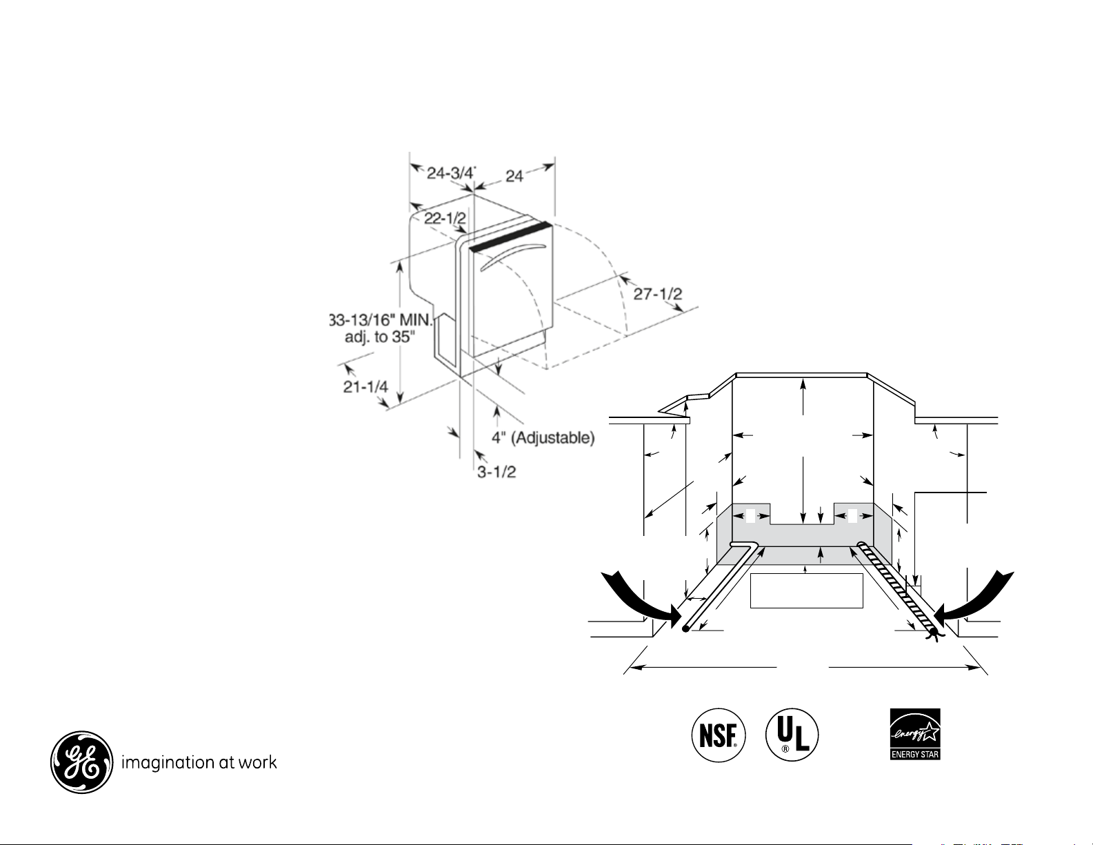
Dimensions and Installation Information (in inches)
Electrical Rating
Voltage AC.......................................................... 120
Hertz..................................................................... 60
Total connected load amperage............. 9.9
Calrod® heater watts max........................ 875
For use on adequately wired 120-volt,
15-amp circuit having 2-wire service
with a separate ground wire. This appliance
must be grounded for safe operation.
Installation Information: Before installing,
consult installation instructions packed with
product for current dimensional data.
††† Add 3/4" for custom panel and additional
room for custom handle
An installation template is packed with these
models and may be obtained in advance.
Order Pub. No. 5-X063.
Hot
water
line on
left
90°
34" to 34-3/4"
Underside
of countertop
to floor
24"
MIN.
55
6
2
19" MIN. from wall
This wall area
must be free of
pipes or wires
4
Plumbing and electrical
service must enter
inside shaded area
24" From wall
Countertop
90°
44
Electrical
wiring is
3" from
cabinet
Electrical
6
wiring on
right
®
For answers to your Monogram,
Profile™
Series or GE® appliance questions, visit our
website at geappliances.com or call GE
Answer Center® service, 800.626.2000.
24" MIN.
Listed by
Underwriters
Laboratories
Specification Revised 3/13
As an ENERGY STAR®
partner, GE has determined
that this product meets the
ENERGY STAR guidelines
for energy efficiency.
250244
PDWT502VII
GE Profile™ Series Dishwasher with SmartDispense™ Technology
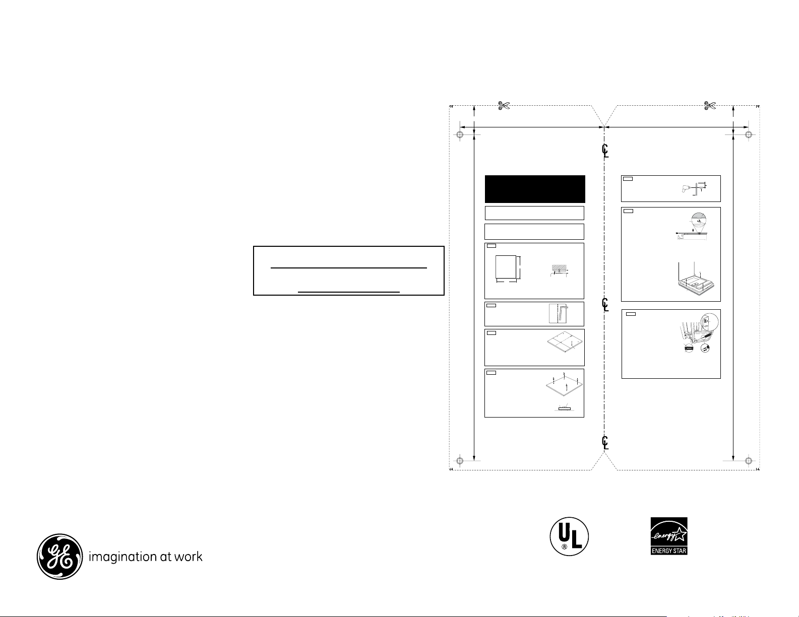
Custom Dishwasher Door Panel Template
GE Pub. No. 031-30569-1
Order GE Pub. No. 031-30569-1
Call 1-800-626-2000
For a full-size panel template with complete
panel installation instructions.
For answers to your Monogram,® Profile™
Series or GE® appliance questions, visit our
website at geappliances.com or call GE
Answer Center® service, 800.626.2000.
For Reference Only
Not to Scale
Drill 3/32"
Pilot Hole
3/32" Deep
Drill 3/32"
Pilot Hole
3/32" Deep
Trim Around Dotted Line
2-9/32"
dishwasher. Use this template to locate mounting screws and spacers on the custom panel.
IMPORTANT
• A custom handle must be installed onto the custom
panel. Install the custom handle 4-1/2" max. from
the top of the panel.
STEP 1 CUSTOM PANEL SIZE REQUIREMENTS
HEIGHT
Panel height must be between 30-1/16" and 30-1/4".
• If the panel height is more than 30-1/4" it will
prevent the door from swinging open.
• If the panel height is less than 30-1/16" it will not
cover the dishwasher door frame.
25-9/16"
STEP 2 DRAW CENTERLINE
• Place the custom panel on a flat surface with appearance side
down.
• Locate the vertical center of the panel at the top.
• Use a carpenters square to draw a centerline from top to bottom.
STEP 3 ALIGN TEMPLATE TO PANEL
• Trim template on the dotted line along all sides.
• Place the template on the panel aligned with the top edge and
the centerline. Use tape to hold in place.
IMPORTANT: If the template is not aligned with the top edge of the
panel, the 1/2" minimum gap will not be maintained. This 1/2" minimum
gap must be maintained to prevent condensation and damage to the
control panel from screw heads.
• Use an awl to mark the screw hole locations indicated on the
template. Remove the template.
STEP 4 INSTALL MOUNTING SCREWS AND SPACERS
If the panel is less than 3/4" thick, shorter screws must
be used. Use #8 x 1/2" screws for 1/2" thick panels (not supplied).
• Use a 3/32" drill bit to drill pilot holes 3/32" deep in the marked
locations.
Note: The custom panel is secured to the dishwasher door with
the spacers and screws provided. The spacer will slip into the
keyhole slots on the dishwasher door.
• Drive the supplied #8 x 5/8" Phillips truss head steel screws
through the spacer and into the panel.
• Install remaining spacers and screws as indicated in the marked
locations.
11-5/16"
3/4" Thick Custom Panel
Template Instructions for
Top Control Integrated Profile and
Monogram Dishwasher Models
The custom panel should be sized to your installation situation. See Step 1. For easier
installation the custom panel and custom handle should be attached before installing the
30-1/16" Min.
30-1/4" Max.
23-3/4"
Top of Panel Top of Panel
11-5/16"
STEP 5 INSTALL CUSTOM HANDLE
A custom handle must be installed onto the panel
before the panel is secured to the dishwasher door.
• The handle should be installed so that it aligns with
adjacent drawer handles, or 4-1/2" max. from the
top of the panel. Secure the handle in the same
manner as cabinet handles. Screws must be
countersunk into the panel.
STEP 6 INSTALL ASSEMBLED PANEL
• Secure the panel to the door by inserting the top
and bottom mounting screws with spacers into
the matching keyhole slots.
PARTS INCLUDED:
(4) Spacers
(4) #8 x 5/8" Phillips truss head stainless steel screws
(3) #8 x 1-3/4" Phillips truss head stainless steel
wood screws
(2) Heavy duty springs
• The top of the custom panel must be flush
with the top of the door. The 1/2" minimum gap
between the top of the door and the bottom of the
countertop must be maintained.
Countertop
1/2" min.
Minimum 1/2" Gap
for Clearance
WIDTH
Panel width must be 23-3/4".
• If the panel width is less than 23-3/4" it will not
cover the dishwasher frame.
IMPORTANT: To ensure optimum door balance
performance, the custom panel must not weigh more
than 14 lbs.
Mark Center
Screw Holes
Screw
Spacer
• Make sure all 4 spacers engage the keyhole slots.
• Press the panel against the door and push
downward until the spacers are fully engaged
into the key hole slots. The panel should align
evenly with the top and sides.
• Stand the dishwasher upright.
• Open dishwasher door and drive the supplied
#8 x 1-3/4" truss head screws. Drive one screw at
the top and one on each side as shown, through
the inner door and into the custom panel.
WARNING: Do not overtighten screws. Excessive
tightening of the screws could damage door edges.
STEP 7 INSTALL DOOR SPRINGS
The dishwasher is shipped from the factory with a
temporary set of balance springs. Use the heavy duty
springs provided and the adjustment holes in the
cable to balance the door after the custom panel
is installed onto the dishwasher.
• With the dishwasher on the wood skid, close and
latch the door.
• Remove and discard both door springs.
• Attach the new heavy duty door springs. Engage
the end with the short hook into the support leg
and the long hook into the cable.
• Open and close the door.
• If the door drops open when released, increase
spring tension. If the door closes when released,
decrease tension.
Listed by
Underwriters
Laboratories
Trim Around Dotted Line
Screws Must
Be Countersunk
Into Panel
4-1/2" Max.
From Top
of Panel
Handle
Custom
Door Panel
Custom
Panel
Dishwasher
Door
Shoulder Washers
Engage Keyhole
Slots
Custom
Panel
Use This
Mounting
Pulley
Shoulder
TIP: If the door does not open easily or falls too
quickly, check spring cable routing. The cable is held
in place by “shoulders” on the pulley. Check to be
sure the cable has not slipped over the pulley
shoulders.
IMPORTANT: Adjust both balance springs to the
same amount of tension to prevent excessive door
twisting during use.
Trim Around Dotted LineTrim Around Dotted Line
Correct Spring
Cable Routing
Decrease
Tension
Increase
Tension
As an ENERGY STAR®
partner, GE has determined
that this product meets the
ENERGY STAR guidelines
for energy efficiency.
2-9/32"
Drill 3/32"
Pilot Hole
3/32" Deep
25-9/16"
Hole
Drill 3/32"
Pilot Hole
3/32" Deep
Specification Revised 3/13
250244
 Loading...