

GE PFS22MIWCWW, PFS22MIWCBB, PFS22MIWBWW, PFS22MIWBBB, PFS22MIWAWW Owner’s Manual
...
geocom
Safety InsTtrudions ........... 2, 3
N
©
Operating Instru_tions
Additional Features ............. 9
Automatic Icemaker . .......... 12
Controls .................... 4-6
Crispers and Paras ............. 10
Freezer ...................... 11
Shelves and Bins ............. 8, 9
VVater Filter ................... 7
Care and Cleaning ........ 13-15
Installation Instructions
Installing the Refligerator . . . .l 7-21
Installing the _4'ater i,ine ..... 31-33
Preparing to Install
the Refiigerator . .............. 16
Removing and Replacing the
Freezer Drawer ............ 22, 23
Reversing the Door Swing
(Single Door Refrigerator
Models only) .............. 24-27
Removing and Replacing
the Doors (Double Door
Refrigerator Models only) .... 28-30
Models20and22
Cong6lateur inf>rieur
R frig&ateurs
La section fran_aise commenceh la page 47
Congelador inferior
Refrigeradores
Laseccion enespa#olempiezaen la pagina89
Troubleshooting Tips ....... 34-38
Normal Operating Sounds ...... 34
Consumer Support
Consumer Support ..... Back Cover
Performance Data Sheet ........ 45
Product Registration
for Canadian Customers ..... 41,42
Product Registration
for U.S. Customers ......... 39, 40
VVarranty for Canadian
Customers ................... 43
_4'arranty for U.S. Customers ..... 44
Write the model and serial
numbers here:
Model #
Serial #
Find these numbe_ on a label
on the right side, near the top of
the refl'igerator compartment.
3828JLSO69D f97B4618P_ 49-60503 01-07JR

IMPORTANTSAFE INFORMATION,
READALLINSTRUCTIONSBEFOREUSING.
WARNING!
Use this appliance only for its intended purpose as described in this Owner's Manual.
SAFETYPRECAUTIONS
When using electrical appliances, basic safety precautions should be followed, including the following:
This reflJgerator must be properl,_ installed
and located in accordance with tile Installation
hlstrucfions before it is used.
Do not allow children to climb, stand or hang
on the shelves in the refl-Jgeratm: They could
damage the refl-Jgerator and seriously iqjm'e
themselves.
Do not touch tile cold surfi_ces in tile fl'eezer
compartment when hands are damp or wet.
Skin max stick to these extremely cold SUll'ilces.
_ Do not store or use gasoline or other flammable
wq)ors and liquids in the viciniP,' of this or anv
other appliance.
Keep finge_ out of tile "pinch point" areas;
clearances between tile doors and between
the doo_ and cabinet are necessarily small.
Be carefid closing (lom_ when children are
in the area.
In refl'Jgeratm_ Mth automatic icemake_,
avoid contact with tile moving parts of tile
ejector mechanism, or with the heating element
that releases the cubes. Do not place finge_s or
hands on tile automatic icemaking mechanism
while the refi-igerator is plugged in.
UnI)lug tile reflJgerator before cleaning and
making repahs.
NOTE: Westronglyrecommendthat any servicingbe
performedby a quafified individual
Setting either or both controls to 0 (off) does
not reil/ove power to tile light circuit.
{ Do not reti'eeze frozen toods which have
thawed complemly.
A DANGER!RISKOFCHILDENTRAPMENT
PROPERDISPOSALOFTHEREFRIGERATOR
Refrigerants
of tile past.,lunked or abandoned reflJgerators are
Child entral)inent and suffocation are not problems
still dangerous...exert if they will sit for 'ijust a few
daxs." If _ou are _*etting rid of xom" old refri_*eratm;
please follow tile instructions below to help prevent
accidents.
Before YouThrewAway YourOldRefrigerator
All refi'igeration products contain refi'igerants,
which under fe(leral law must be removed prior
to product disI)osal. If you are getting rid of
an old reli'igeration product, check with tile
company handling tile disposal about what
to do.
or Freezer:
_ke off tile dome.
i,eaxe tile shelxes in place so that children may
not easiE climb inside.
USEOFEXTENSIONCORDS
Because of potential safety hazards under certain conditions, we strongly recommend against
the use of an extension cord.
However, if you must use an extension cord, it is absolutelx necessary that it be a Ui_-listed (in tile United
States) or a CSA certified (in Canada), B-wire ,gr°/mding, t_,l)e appliance extension cord having a gro/mding
2
t)l)e I)lu'"-,and outlet and that tile electrical rating of tile cord be 15 amperes (minimum) and 12(1 xolts.

WARNING!
HOWTOCONNECTELECTRICITY
Donot, under anv circumstances, cut or remove the third (ground) prong from the power cord.
For personal safe_ this appliance must beproperly grounded.
ge.com
The power cord of this appliance is equipped
with a 3-prong (gromMing) plug which mates
with a standard 3-prong (grounding) wall outlet to
minimize the possibili_, of electric shock hazard
fi'om this appliance.
Have the wall outlet and circuit checked by a
qualNed electridan to make sure the outlet is
properly gromMed.
Where a standard 2-prong wall outlet is
encountered, it is your pex_onal responsibili_' and
obligation to have it replaced with a propedy
grounded 3-prong wall outlet.
The refl_igerator should always be plugged into its
own individual electrical outlet which has a voltage
rating that matches the rating plate.
This provides the best pe_imnance and also
I_rexents oxerloading, house wiring circuits which
cotfld cause a fire hazard from oxerheated wires.
Never mq)lug yore" refrigerator by pulling on the
power cord. Mways grip plug firefly and pull
straight out ti'oln the outlet.
Repair or replace immediately all power cords that
have become fl'ayed or otherwise damaged. Do not
use a cord that shows cracks or abrasion damage
along its length or at either end.
\4]_en moving the refl_igerator away fl'om the
wall, be carefld not to roll over or damage the
power cord.
READANDFOLLOWTHISSAFETYINFORMATIONCAREFULLY.
SAVETHESEINSTRUCTIONS

About the controlswith
temperature setting& (forother models, see next page)
NOTE: Therefrigeratorisshipped wilt7protective film coveringttTetemperaturecontrols.
If ttTisfilm wasnot removedduringinstallation,removeit now
Thetemperature controls are preset in the factory at 37°t: for the refrigerator compartment
and O°Ffor the freezer compartment. Allow24 hours for the temperature to stabilize to the
preset recommended settings.
Thetemperature controls can display both the SET temperature as well as the actual
temperature in the refrigerator and freezer. The actual temperature may vary slightly from
the SETtemperature based on usage and operating environment.
Setting either or both controls to OFFstops cooling in both the freezer and refrigerator
compartments, but does not shut off electrical power to the refrigerator.
Changingthe Temperature
To change the temperature, press and release the
WARMER or COLDER pad. The SETlight will come
on and the display will show the set temperatm'e.
To change the temperature, tap either the
WARMERor COLDERpad tmfil the desired
temperatm'e is displayed. Refl_igerator temperatm'es
can be ac!iusted between 34°F and 47°F and the
fl'eezer teInI)eratures can be ac!iusted between
-6°F and +8°E
Once the desired temi)eratm'e has been set,
the temperatm'e display will retm'n to the actual
refl]gerator and fl'eezer tenq)eratures after B
seconds. Several ac!jusmlents may be required.
Performance Air Flow System
The Pex-fbmaance ?dr Flow System is designed to
maximize teml_eratm'e control in the refl_igerator
and fl'eezer compartments. This tmique special
teatm'e consists of the _&JrTower along the back
Each time you ac!iust controls, allow 24 horns fiw the
refrigerator to reach the temperatm'e you have set.
Toturn the cooling systemoff, tap the WARMER pad
fbr either the refl_igerator or the fl'eezer tmtil the
display shows OFF.To turn the unit back on, press the
COLDERpad flw either the refl'igerator or fl'eezei:
The SETlight will ilhmfinate on the side you
selected. Then press the COLDERpad again (on the
side where the SETlight is illuminated) and it will
go to the preset points of O°Ffiw the fl'eezer and
37°Ffi)r the refl_igeratm: Setting either or both
controls to Off stops cooling in both the fl'eezer
and refi'igerator compartments, but does not shut
off electrical power to the refl'igeratm:
wall of the refl'igerator and the _Mr Tmmel on the
bottom portion of the fl'eezer rear wall. Placing
food in fl'ont of the lou\'e_ on these components
will not affect perlbm_ance.
4
About TurboCooEM(on some models) ge.oom
How it Works
TurboCoolrapidly cools the reii_igerator
c()mi)artn/ent in order to more quickly
cool fi)ods. Use TurboCoolwhen adding a
large amount oftood to the reflJgerator
compartment, putting away foods after they
have been sitting ()tit at rOOlll temperature
or when putting away wam_ leftovers. It can
also be used if the refl_igerator has been
without power for an extended period.
Once acfi\:_ted, the compressor will tm'n on
immediately and the rims will cycle on and
off at high speed as needed tot eight hom_.
The compressor will continue to run tmtil
the refl_igerator compartment cools m
approximately 34°F (l °C), then it will cycle
on and off to maintain this setting. _Mter 8
hom_, or if TurboCoolis pressed again, the
refl_igerator compartment will return to
the original setting.
How to Use
Press TurboCooLThe refrigerator
temperatm'e display will show L c.
_Mter TurboCoolis complete, the
refl_igerator comi)amnent will return
to the original setting.
NOTES: The refrigerator temperatm'e
cannot be changed dining
rurboCoot
The fl'eezer temperature is not
affected during TurboCoot
_._]ten opening the refrigerator
door dtwing TurboCool,the tiros
will contintle to rtln if they have
cycled on.
About Door Alarm (onsomemodels)
The door alama will sotmd if either
door is open fin" more than 2 minutes.
The beeping stops when w)u close
the door.

Aboutthe controlswith numberedsettings.
NOTE: Therefrigeratoris shipped with protective film coveringthe temperaturecontrols.
If this film was not removedduringinstallation, removeit now
Initially, set the refrigerator control at5 and the freezer control at5 and allow24 hours
for the temperature to stabilize.
Several adjustments may be required. Adjust the controls one increment at a time, and
allow24 hours after each adjustment for the refrigerator to reach the temperature you
have set.
Setting either or both controls to 0 stops cooling in both the refrigerator and freezer
compartments, but does not shut off electrical power to the refrigerator.
Performance Air Flow System
The Pe_tom_ance _Mr Flow System is designed to
maximize temperattu'e control in the refl_igerator
and fl'eezer compartments, This tmique special
teatm'e consists of the _dr Tower along the back
wall ot the refligerator and the _dr Tmmel on the
bottom portion of the fl'eezer rear wall. Placing
fi)od in fl'ont of the louve_ on these components
will not affect perfi)m_ance.
Aboutthe water filter.(onsomemodels) ge.com
Water Filter Cartridge
The _ater filter cartridge is located im_the
back Iq_per right comer of the re{_'igerator
col]_paFtm el_ t,
When to Replace the Filter
There is a replacement h_dicator
light {br the _<_ter filter cartridge ol_ the
temperatm'e display: This light Will t_'_
Omm_ge to te]] v<)l_ that _ol_ m_eed to replace
the {i]ter seem The {]]ter cartridge sholl]d
be replaced _hen the rep]acemem_t
h_dicator light rams red or if the flo_
of _ater to the dispenser or icemaker
decreases.
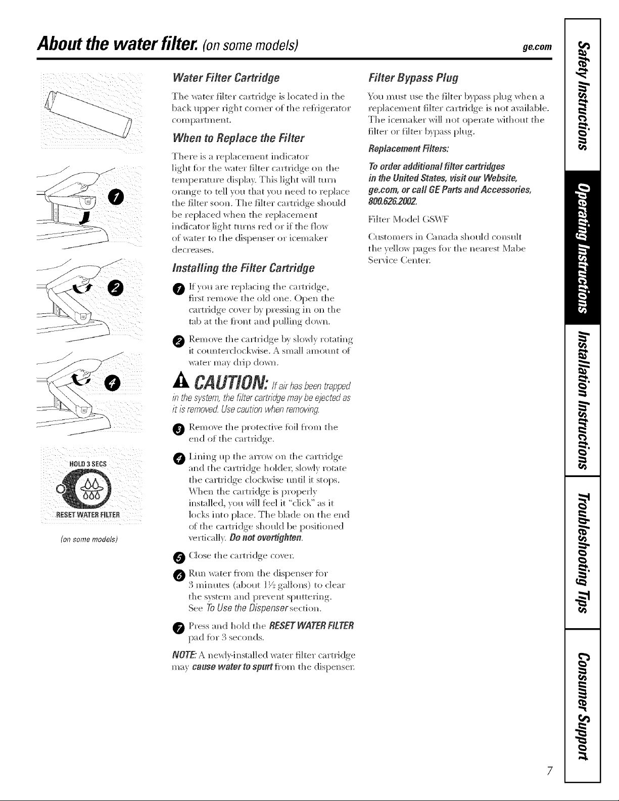
lnstalling the Filter Cartridge
0 Jf yol_ are rep]acim]g the cartridge,
first remo\e the old else. ()pe]_ the
cartridge cover b} pressim_g in on the
tab at the Jh'o_t aN_d Im]lim_g dome.
0 Remove the cartridge b} S]()_r]} rotatim_g
it com)terdockwise. _k small amom)t of
water may drip (]o_r_.
Filter Bypass Plug
Yo_* m _*st me tl_e I]her b}l_ass pl_g M_ e_ a
replacement {i]ter cartridge is _ot ;wa]];_b]e.
The ]cemaker _i]] _ot operate witho_t the
ReplacementFilters:
Toorderadditional filter cartridges
in theUnitedStates,visit onr Website,
ge,com,or car GEParts andAccessories,
800,8262002.
Filter Mode] (;SWF
Cmtomers i_ Cam_da should comtdt
d]e_e]]ow [ ,)ages fbr the _earest Mabe
Sepd ce Cente]:
HOL_3$EC$
t
RESETWATERFILTER
(o/7 some models)
_k C_UT_ON: lf airhasbeentrapped
b tile swtem, the f//ter cartridgemay be ejectedas
it is removeo{ Use caution when rernov/ng.
O Remove the protective foil f]'om the
end _ff"the cart _tidge.
0 l,h_h_g _1>the arro_ o]_ the cartridge
a_d the camidge ho]de_; SIOWHVrotate
the cart_{dge c]ockx_ise Imti] it sto[)s.
\_']]e]_ the cartridge is properly
h_sta]]ed, yo_ wi]] feel it "click" as it
locks h_to piece. The blade o_ the end
of the ca rtri dye sh o_] d be posi tion ed
vertica]h. DO not overdghten.
O Close d_e cartridge coven
O Rm_ _ater f}'om the dispe]lser {or
3 mhmtes (abo_t ] _/__gallons) to clear
the system a]]d pro', ent sp_tte_J_g
See ToUse theOispenser sectio_.
Press a_d hold the RESETWATERFILTER
pad fbr 3 seco_ds.
NOTE"A _ ew]>] _ stall ed wa ter fi]ter ca rt]J dye
may cause waterto sp_rt Imm the dispe_se_:
7

Abouttheshelvesandbins.
Not all features are on all models.
Rearranging the Shelves
Shel;es in the refrigerator cOn_l)artment are a(!iustable.
Refrigerator Compartment
To remove:
io 0
0 Tilt the shelf up at the fl'ont.
0 I,ifl the shelf u I) at the back and
bring the shelf ()tit.
Some models have wire shelves that
can be adjusted in the same mam?e_
Toreplace:
0 _'_hile tilting the shelf up, insert the top
hook at the back of the shelf in a slot
(m the track.
0 I,ower the fl'ont of the shelf until the
bottom of the shelf locks into place.
i 0
Spillproof Shelves (onsomemodels)
Spillproof shelves have special edges to
hel I) prevent spills fl'om dripping to lower
shelves. To relnove or rel)la('e the shelves,
see RearrangingtheShelves,
Slide-Out Spillproof Shelf (onsomemodels)
The slide-out spillproof shelf allows you
to reach items stored behind othei_. The
spedal edges are designed to hel I) l)revent
spills fl'om dripping to lower shelves.
To remove:
0 Reinove all items from shell
0 Slide the shelf ()tit until it stops.
iift the fl'ont edge of the shelf until the
central tabs are above the fl'ont 1)m:
0 Continue pulling the shelf fi)rward
until it can be removed.
Toreplace:
0 Place the rear shelf tabs just in fl'ont of
the central notches on the shelf fl'ame,
0 Slide the shelf in un61 the central tabs
are slightly behind the fl'ont baI;
0 i,ower the shelf into place until it is
horizontal and slide the shelf in.
Make surethat the she/f sits fiat after re/hstaiiation
anddoesn'tmove free/y fromside toside.
Make sureyoupush the shelvesall theway/h
before youclose the door
8

ge.com
Fingerhold
mgger
Adjustable Bins on the Door
A(!justable bins can easily be carried fron]
retiJgerator to work area.
To remove: IJfl bin straight ill), then
pull out.
To replace or relocate: Engage the bin in the
molded supports (ff the doox; and push in.
Bin will lock in place.
]'he snugger helps prevent tipping, spilling
or sliding of small items stored on the door
shelf. (;_'ip the finger hold near the rear of
the snugger and move it to fit veto" needs.
Abouttheadditional features.
Not all features are on all models.
Shelf Saver Rack (onsomemodels)
Slide-out beverage rack holds twelve cans of
soda or two wine/wamr bottles (lengthwise).
It can be removed fi)r cleaning.
To remove, slide the rack ()tit to the stop
position, lift the rack up and past the stop
position and lift it ()tlt.

Aboutthe crispersandpans.
Not all features are on all models.
Fruit and Vegetable Crisper
Excess water that ma_ accunmlate in the
bottom of the (h'awels or under the (h'awei_
should be wiped dry.
Adjustable Humidity Crisper (onsomemodels)
Slide the control all the way to the Slide the control all the wax to the LOW
HIGHsetting to proxide high humidit_ .settin,,_ to proxide lower humidity, lex els
recommended fi)r most xegetables, recommended fi)r most fl'uits.
Snack Pan (on some models)
This pan can be mo_ed to the most useflfl
location fin" )ore" fmnil)'s needs.
To remove, slide the pan out to the stop
position, lilt the pan u l) and past the stop
position and lift it out.
Adjustable Temperature Dell Pan (onsomemodels)
When the pan is placed in the 7th slot fl'om
the bottom of the track and the lever is set
at COLDEST, air fl'om the fl'eezer is torced
around the pan to kee I) it very cold.
You can move the pan to any location if
you don't want the extra cold storage.
The settings can be a(!justed anywhere
bet_ven cold _ and coldest _ _.
X&]_en set at cold, the pan will stay at the
normal refl_gerator temperature.
The coldest setting provides the coldest
storage area.
Crisper Removal
To Remove:
These drawei_ can be removed easily 1)v
lifting up slightl)while pulling the drawer
past the stop location.
When the door cannot be fully opened,
i'eln()x'e the drawer fi_rth est from the door
filst. Make sure the drawer closest to the
door is fifllv closed. There is a latch at the
front of the center slide rail. Push down on
the latch and slide the center slide rail, to
which the drawer is attached, a_)' fl'om the
dora: I'_.eInove fl_e drawer
10
Aboutthe freezer, ge.com
Not all features are on all models.
[ J
Appearance and features may vary
Appearancemayvary
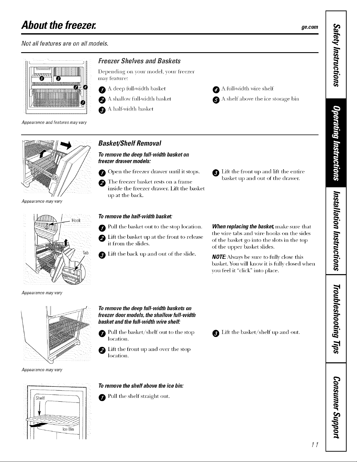
Freezer Shelves and Baskets
0 _kdeep fld]-widd_ basket
5 half'width basket
Basket/Sheff Removal
Toremove the deep full-width basket on
freezer drawer models:
0 (-)pen the freezer drawer tmtil it stops.
@ The fl'eezer basket rests on a fl'ame
inside the fl'eezer (h'awe_: i,ift the basket
up at the back.
To remove the half-width basket:
0 Pull the basket out to the stop location.
O IJfl the basket up at the fl'ont to release
it from the slides.
Lift the back up and out of the slide.
_ fld]-width wire shelf
Lift the fl'ont up and lilt the entire
basket up and out of the (h'awe_;
When replacing the basket make sure that
the Mre tabs and wire hoolcs on the sides
of the basket go into the slots in the top
of the uI)per basket slides.
NOrE.AI vsbe sure to fldly close this
basket. You will know it is flfllv closed when
wm teel it "click" into place.
Appearance may vary
Appearance may vary
Shelf
IceBin
Toremove the deep fidl-width baskets on
freezer door models, the shallow full-width
basket and the full-width wire shelf."
Pull the basket/shelf out to the stop
location.
Lift the fl'ont tlI) and oxer the stop
location.
Toremove the sheff above _e ice bin:
Pull the shelf straight out.
Lift the basket/shelf up and out.
11

Abouttheautomaticicemake
A newly instafled refrigerator may take 12 to 24 hours to begin making ice,
Power
Switch
", Icemaker
PowerLight FeelerArm
Automatic Icemaker (onsome models)
The icemaker will produce seven cubes
per c?de-_approximatel? 100-130 cubes
in a 24-hour period, dependim_g on f]'eezer
[em[>emmre.... mm_ber of door o[>eni m_gs.
and ethel" Hse conditiom_s.
See below for how to access ice amid reach
th e power switch.
If the re}_ige_tor is operated before the
water co]mecdom_ is made to the icemakel;
set the po_er s*dtch h_ the O (off]posit]ore
The ]cemaker power light will mrm_green
when the }_'eezer light s,Gtc]] is pressed im_
or whem_fl_eh'eezer door is dosed.
_hen the re{_ige_:_tor has been com_ected
to the water suppl? set the power switch to
the / (on)positiom
The ]cemaker will fill with water when it
cools to ]5°F (-]0°C). A needy h_stalled
re{}Jgemtor may take ] 2 to 24 hems to beg-h_
ma]dm_g ice o_bes.
}i_l_ will hear a bl*zzh_g seined each time
the ]cemaker f?Hs vvri[h wateL
Throw a_av the _'st {ew batches of ice to
allo_ the water li_e to deal
Be sm'e m)thi_g h_terferes with the sweep
of the feeler arm.
_l]en the bh_ {ills to the le', el of the {eeler
arm, the icemaker will stop prod_ci_g
ice. It is _ormal fkn" se',e_:d ofl)es to be
ff ice is _ot _*sed }_'equent]y; old ice o*bes
_rd]] become c]ol*dy, taste stale a_/(] shri_/k.
NOTE:b homeswithlower-than-averagewater
pressure,youmayheartheicemakercycb md@b
timeswf_enmakingonebatchof ice.
Ice Bin
Toreach the power switch.
/2
Accessing Ice andReaching
the Power Switch
Toroach the icemaker power switch, pull the
shelf above the ice bin straight out. _wa}:s
be sure to replace the shelE
Toaccessice,simply pull the bin ti>rward.
Icemaker Accessory Kit
If yore" refligerator did not come ah'ea(h
equipped with an automatic icemake_;
an icemaker accessory kit is axailable at
extra cost.
To Use the Dispenser (on some models)
The water dispenser is located on the left
wall inside the reti-igerator compartment.
To dispense water:
Hold the glass against the recess.
Push the water dispenser button.
0 Hold the glass tmderneath the
dispenser fi)r 2-3 seconds after
releasing the dispenser button.
Wamr may continue to dispense
alter the button is released.
7-0 aCCeSS ice,
Check the back of the refligerator fi>r
the specific icemaker kit needed tilr
VO/II" model.
If nowaterisdispensedwhentherefwemtorisfirst
installed,theremaybeairinthewaterlinesystem.
Pressthedispenserbuttonforat/east2minutesto
removetrappedair fromthewaterlineandtoill/the
watersystem.Duringthisprocess,thedispenser
noisemaybeloudastheairispurgedfromthe
waterlinesystem.Toflushoutimpuritiesin the
waterline,throwawaythefirst6glassfulsofwater
NOTE:Toavoidwaterdeposits,the dispenser
shouldbecleanedpefiodicaflybywipingwith a
cleancloth orsponge.
Careand cleaning oftherefrigerator, ge.cem
Cleaning the Outside
The door handles and trim. Clean with a cloth
daml)ened with soapy water: L)_T with a sott
cloth. Do not use wax on the door handles
and trim.
Keep the outside clean. Wipe Mth a clean
cloth lightly dampened Mth kitchen
appliance wax or mild liquid dish
detergent. D_3' and polish with a clean,
soft cloth.
Do not wipe the refrigerator with a soiled dish
cloth or wet towel Thesemay leave a residue
that can erode the pa/n_ Do not use scouring
pads,powdered cleaners, bleach or cleaners
contein/ng bleach because these products can
scratch and weaken the paint finish.
Cleaning the Inside
The stainless steel panels and doorhandles.
Stainless steel (on some models) can be
cleaned with a commerdallv available
stainless steel cleanex: A spray-on stainless
steel cleaner works best.
Do not use appliance wax or polish
on the stainless steel,
Tohelp prevent odors, leave an open be× _:,t
baking soda in the reflJgerator and fi'eezer
COIIII)_I I'[ll/ents.
Unplug the refrigerator before cleaning. If this
is not practical, wring excess moisture ()tit
of sponge or cloth when cleaning arotmd
switches, lights or controls.
Lrse an appliance wax polish on the inside
sml'hce between the do(n_.
Use warn/ water and baking soda solution--
about a tablesl)oon (15 ml) of baking soda
to a quart (l liter) oI water: This both cleans
and neutralizes odo_. Rinse and wipe (h_'.
_Mter cleaning the door gaskets, apply a
thin laver of petrolemnjelly to the door
gaskets at the hinge side. This helps kee I)
the gaskets ti'om sticking and bending out
of shape.
Avoid cleaning cold glass shelves with hot water
because the extreme temperature difference may
cause them to break. Handle glass shelves
carefull_z Bumping tempered g/ass can cause
it to shatter
Donot washanyplasticrefrigeratorpartsin
thedishwasher
13

Careand cleaning oftherefrigerator.
Behind the Refrigerator
Be caretul when moving the refl_igerator
away fl'om the wall. M1 types of floor
coverings can be (lamaged, particulady
cushioned coverings and those with
embossed stiFf,ices.
Pull the reti_igerator straight out and return
it m position by pushing it straight in.
Moving the refl_igerator in a side direction
may result in damage to the floor covering
or refrigerator:
Preparing for Vacation
When pushing the refrigerator back, make sure
you don't rofl over the power cord or icemaker
supply line (onsome models).
For long \;l(-ations or absen(-es_ i'elllOVe
food and m_plug the reli_igerato_: Move
the fl'eezer control to the 0 (Olg)position,
and clean the interior with a baking soda
solution of one tablespoon (l 5 ml) of
baking soda to one quart (l liter) of _;_m_:
i,eave the clom_ open.
Set the icemaker power switch to the 0 (off)
position and shut off the water supply to
the reffigemtm:
Preparing to Move
Secm'e all loose items such as base grille,
shelves and drawe_ by taping them
secm'elv in place to prevent damage.
X4]mn using a hand truck to move the
refl_igeratot; do not rest the fl'ont or back
of the refrigerator against the hand truck.
This could damage the reffigeratm: Handle
only from the sides of the reffigeratm:
If the temperature can drop below
fl'eezing, have a qualified servicer drain the
water supply systeln (on SOlne models) to
prevent serious propei F dalnage due to
flooding.
Besurethe re{ngemtor staysin anupwht
positionduringmoving.
/4
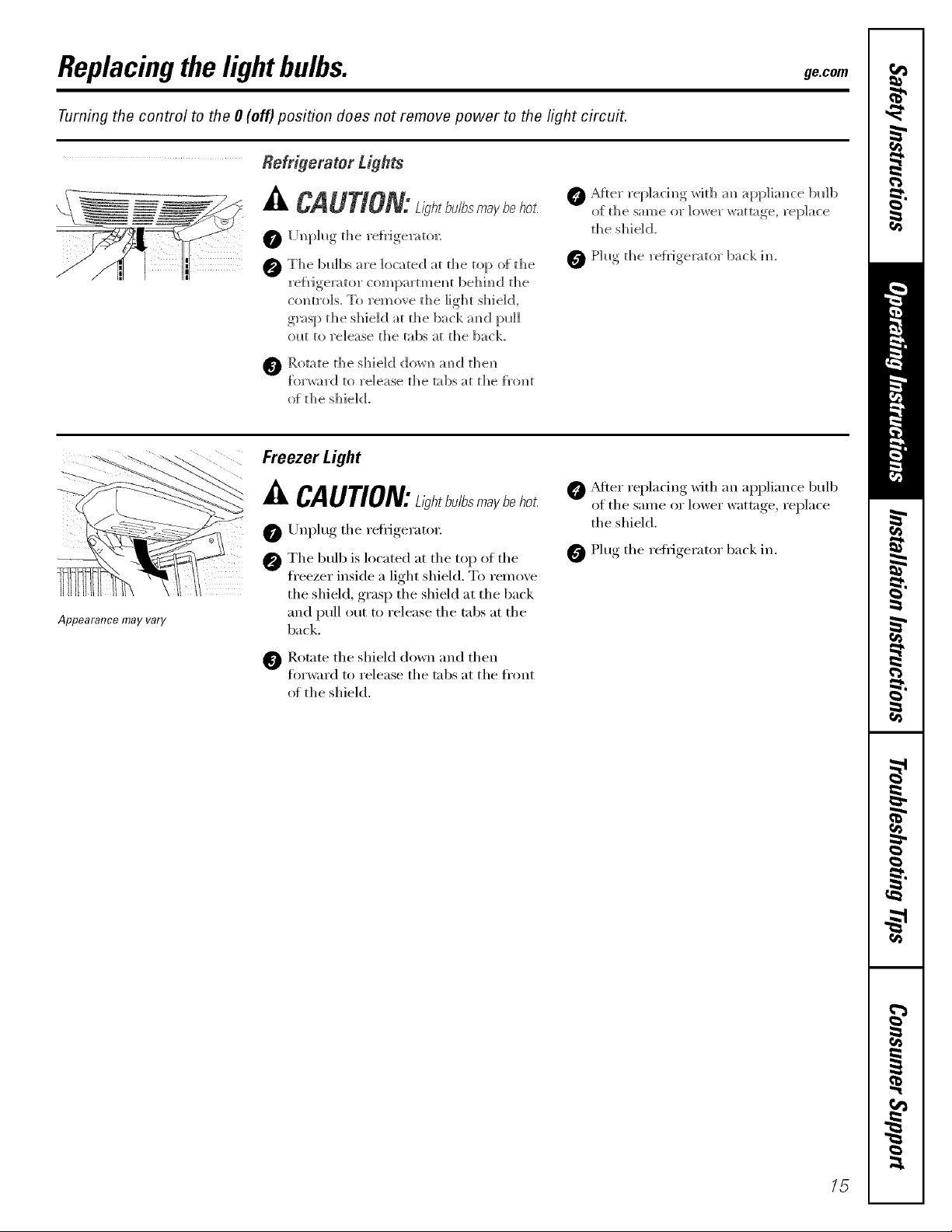
Replacingthelightbulbs, gecom
Turning the control to the 0 (off) position does not remove power to the light circuit.
0 Cf_er re[_]acim_g_ wit]] an appliance bull)
o[ the sam e or ]ower wattage, rep]ace
the sh ie] d.
0 Phlg the re{}:igerator back im
_]_ P.otate the s]lie]d dov,']_ m_d t]le]_
forward to release the tabs at the f}'<mt
of t h e sh ie] d.
Freezer Light
Appearance may vary
_kCAUTION:ah_b.Ib,_ b_ho_
Unplug the reli'igerato_:
0 The bulb is locamd at the top of the
fl'eezer inside a light shield. To remove
the shield, grasp the shield at the back
and pull out to release the tabs at the
back.
_]b Rotate the shield down and then
forward to release the tabs at the fl'ont
of the shield,
0 _Mter replacing with an appliance bulb
of the same or lower wattage, replace
the shield.
0 Plug the refl_igerator back in.
15

Installation
Refrigerator
Instructions
I Questions? Call 800.GE.CARES (800.432.2737) or Visit our Website at: ge.com
BEFORE YOU BEGIN
Read these instructions completely
and carefully.
• IMPORTANT - Savethese
instructions for local inspector's use.
• IMPORTANT - Observeall
governing codes and ordinances.
• Note to Installer - Be sure to leave these
instructions with the Consumer.
• Note to Consumer - Keep these
instructions for future reference.
• Skill level - Installation of this appliance
requires basic mechanical skills.
• Completion time - Refrigerator Installation
• Proper installation is the responsibility of
the installer.
In Canada, call 1.800.361.3400 or Visit our Website at: www.geappliances.ca
PREPARATION (cont.)
WATER SUPPLY TO THE ICEMAKER AND
DISPENSER (ON SOME MODELS)
If the refrigerator has an icemaker, it will have
to be connected to a cold water line. AGE water
supply kit (containing tubing, shutoff valve,
fittings and instructions) is available at extra
cost from your dealer, by visiting our Website
at ge.com (in Canada at www.geappliances.ca)
or from Parts and Accessories, 800.626.2002 (In
Canada 1.888.261.3055).
TOOLS YOU MAY NEED
20 minutes
Water Line Installation
30 minutes
Adjustable Wrench Ratchet/Driver
Models 20 and 22
I
3/8" and 10 mm Socket
• Product failure due to improper installation
is not covered under the Warranty.
PREPARATION
MOVING THE REFRIGERATOR INDOORS
If the refrigerator will not fit through a doorway,
the refrigerator door and freezer drawer or door
(depending on model) can be removed.
• To remove the refrigerator door, see Step 1
in the Reversing the Door Swing section.
• To remove the freezer drawer, see the
Removing the Freezer Drawer section.
• To remove the freezer door, see Steps 2
and 3 in the Reversing the Door Swing
section.
1/4" Outer Diameter
Compression Nut
and Ferrule (sleeve)
(icemaker models only)
===================================================================
3/32" Allen wrench
supplied for use on
Stainless steel
refrigerator handles
(on some models)
Phillips Head Screwdriver
1/4" Allen wrench supplied
for changing handle
fasteners location
(on some models)
16

mnstaliation mnstructions
INSTALLING THE REFRIGERATOR
REFRIGERATOR LOCATION
• Do not install the refrigerator where the
temperature will go below 60°F (16°C) because it
will not run often enough to maintain proper
temperatures.
• Do not install the refrigerator where the
temperature will go above IO0°F (37°C) because it
will not perform properly.
• Install it on a floor strong enough to support it fully
loaded.
CLEARANCES
Allow the following clearances for ease of installation,
proper air circulation and plumbing and electrical
connections.
Sides 1/8" (4 mm)
Top 1" (25 mm)
Back 1" (25 mm)
REMOVE TOP CAP (onsomemodels)
• IMPORTANT NOTE: This refrigerator is34-1/2" deep.
Doors and passageways leading to the installation
location must be at least 36" wide in order to
leave the doors and handles attached to the
refrigerator while transporting it into the installation
location. If passageways are lessthan 36", the
refrigerator doors and handles can easily be scratched
and damaged. The top cap and doors can be removed
to allow the refrigerator to be safely moved indoors.
Start with Step A.
• If it isnot necessaryto remove doors, skip Step A.
Leave tape and all packaging on doors until the
refrigerator is in the final location.
• SKID REMOVAL: ]31t refrigerator to each sideto
remove skid.
• NOTE: Use a padded hand truck to move this
refrigerator. Place the refrigerator on the hand
truck with a side against the truck. We strongly
recommend that TWO PEOPLE move and complete
this installation.
[] Locate and remove the two Phillips head screws
on the top of the refrigerator. Remove the two
screws on each side at the rear of the top cap.
Lift off and remove top cap.
[] Remove the fresh-food door. Refer to Steps 1
through 3 of "Reversing the Door Swing" section.
[] Remove the bottom freezer drawer. Refer to
"Removing Freezer Drawer" section.
[] Move refrigerator to the installation location.
REMOVE TOP CAP (cont.)(onsomemodels)
REINSTALL DOORS, DRAWERS AND TOP CAP
[] Carefully lower the door onto the center hinge.
Reinstall top hinge. NOTE: Ensure the door is
properly aligned to the case top to avoid
readjustment of the door during top cap
reinstallation.
[] Place cap over the top of the refrigerator. Reinstall
the original screws in the top and back of the cap.
[] Reinstall the bottom freezer drawer. Refer to
"Replacing the Freezer Drawer" section.
A=
[] CONNECTING THE REFRIGERATOR
TO THE HOUSE WATER LINE
(icemaker and dispenser models)
A cold water supply is required for automatic
icemaker operation. If there is not a cold water
supply, you will need to provide one. See
Installing the Water Line section.
NOTES:
• Before making the connection to the
refrigerator, be sure the refrigerator power cord
is not plugged into the wall outlet.
• If your refrigerator does not have a water filter,
we recommend installing one if your water
supply has sand or particles that could clog the
screen of the refrigerator's water valve. Install it
in the water line near the refrigerator. If using
GE SmartConnect TM Refrigerator Tubing Kit, you
will need an additional tube (WXO8XIO002) to
connect the filter. Do not cut plastic tube to
install filter.
17
Installation Instructions
INSTALLING THE REFRIGERATOR (cont,)
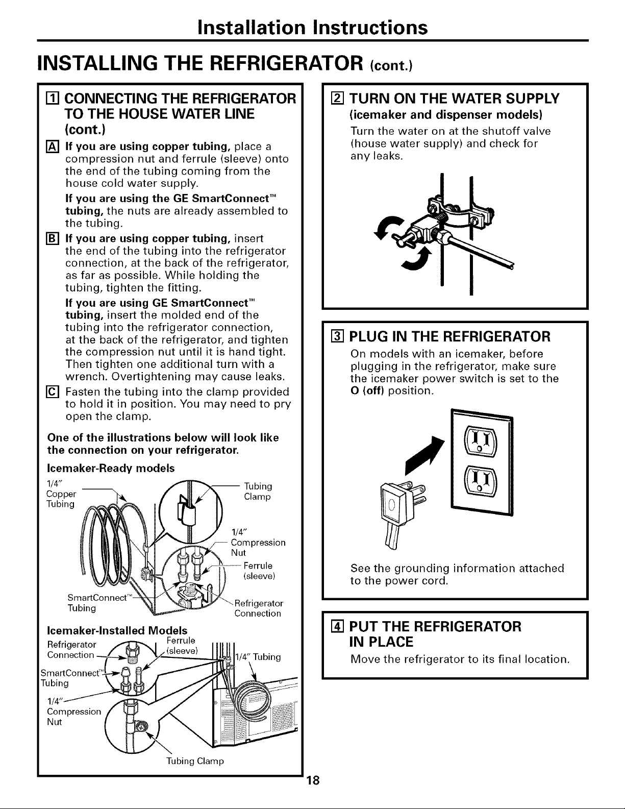
[] CONNECTING THE REFRIGERATOR
TO THE HOUSE WATER LINE
(cont.)
[] If you are using copper tubing, place a
compression nut and ferrule (sleeve) onto
the end of the tubing coming from the
house cold water supply.
If you are using the GE SmartConnect TM
tubing, the nuts are already assembled to
the tubing.
[] If you are using copper tubing, insert
the end of the tubing into the refrigerator
connection, at the back of the refrigerator,
as far as possible. While holding the
tubing, tighten the fitting.
If you are using GE SmartConnect TM
tubing, insert the molded end of the
tubing into the refrigerator connection,
at the back of the refrigerator, and tighten
the compression nut until it is hand tight.
Then tighten one additional turn with a
wrench. Overtightening may cause leaks.
[] Fasten the tubing into the clamp provided
to hold it in position. You may need to pry
open the clamp.
[] TURN ON THE WATER SUPPLY
(icemaker and dispenser models)
Turn the water on at the shutoff valve
(house water supply) and check for
any leaks.
[] PLUG IN THE REFRIGERATOR
On models with an icemaker, before
plugging in the refrigerator, make sure
the icemaker power switch is set to the
O (off) position.
One of the illustrations below will look like
the connection on your refrigerator.
Icemaker-Ready models
1/4" -- Tubing
Copper Clamp
Tubing
1/4"
Compression
Nut
(sleeve)
SmartConnect T_
Tubing gerator
Icemaker-lnstalled Models
Refrigerator Ferrule
Connection
Connection
1/4" Tubing
See the grounding information attached
to the power cord.
[] PUT THE REFRIGERATOR
IN PLACE
Move the refrigerator to its final location.
18

mnstaliation mnstructions
[] REMOVE THE FRESH FOOD
DOOR HANDLE
(For placement in the installation location or
reversal of the handles - on some models)
Stainless steel (on some models):
@ REMOVING
THE DOOR
HANDLE: Loosen
the set screws with
the 3/32" Allen
wrench and
remove the handle.
NOTE: For Double
Door models
follow the same
procedure on the
opposite door.
0 REVERSINGTHE
DOOR HANDLE:
• Remove the
handle mounting
fasteners with a 1/4"Allen wrench and transfer
the handle mounting fasteners to the right side.
• Remove and transfer the plug button and logo
badge to the leftside of the fresh food door.
NOTE:Use a flat plasticedge to prevent damaging
the door. Remove any adhesive on the door with
a mild detergent. Remove the papercovering on
the adhesive backing on the logo badge priorto
carefully attaching the badge to the door.
Plastic handle (on some models):
O REMOVINGTHE
DOOR HANDLE:
Slide the handle
up on the handle
mounting
fasteners and
remove the
handle.
For some models,
depress the tab
on the underside
of the handle and
slide the handle
up and off of the Vlounting Fasteners
mounting
fasteners. (appearance may vary)
0
REVERSINGTHE DOOR HANDLE:
• Remove the handle mounting fasteners with a
3/8" or 10 mm socket wrench and transfer the
handle mounting fasteners to the right side.
• Remove and transfer the plug button and logo
badge to the left side of the fresh food door.
NOTE: Use a flat plastic edge to prevent
damaging the door. Remove any adhesive on
the door with a mild detergent. Remove the
paper covering on the adhesive backing on the
logo badge prior to carefully attaching the badge
to the door.
,Mounting
Fasteners
(appearance may vary)
O_adge
of
Button
lug
utton
Badge
After removing the handle: Move the small plug
button from the top right side of the door top and
insert it into the hole on the opposite side.
(appearance may vary)
[] REMOVE THE FREEZER DOOR
HANDLE
Stainless steel and some plastic handles:
O Loosen the set screws located on the underside
of the handle with the 3/32" (or 1/8" on some
models) Allen wrench and remove the handle.
NOTE: If the handle mounting fasteners need to
be tightened or removed use a 1/4" Allen wrench.
Plastic handle:
Slide the handle to the right on the handle
mounting fasteners and remove the handle.
NOTE: If the handle mounting fasteners need to
be tightened or removed use a 3/8" or 10 mm
socket wrench.
Mounting
fasteners
(appearance may vary)
Slots on back
of handle

Installation Instructions
INSTALLING THE REFRIGERATOR (cont.)
[] ATTACH THE FRESH FOOD
DOOR HANDLE
Stainless steel handle:
Attach the handle
to the handle
mounting
fasteners and
tighten the set
screws with a
3/32" Allen
wrench. Mounting
NOTE: For Fasteners
Double Door
models follow the
same procedure Plug
on the opposite
door.
(appearance may vary)
Plastic handle:
O Attach the handle to the handle mounting
fasteners by aligning the slots with the handle
mounting fasteners.
0 Slide it down until it is firmly locked into
position.
[] ATTACH THE FREEZER DOOR
HANDLE
Stainless steel and some plastic handles:
Q Attach the handle firmly to the mounting
fasteners and tighten the set screws on the
bottom of the handle with a 3/32" (or 1/8"
on some models) Allen wrench.
(appearance may vary)
Plastic handle:
Q Attach the handle to the mounting fasteners by
aligning the slots with the mounting fasteners.
O Slide it to the left until it is firmly locked into
position.
Mounting
fasteners Slots on back of
(appearance may vary)
handle
Mounting
fasteners __
(appearance may vary)
NOTE: A properly locked handle will be centered
on the freezer.
)
Slots on back
of handle
20

Installation Instructions
[] LEVEL THE REFRIGERATOR
The leveling legs have 3 purposes:
1) Leveling legs adjust so the door closes
easily when opened about halfway.
(Front of the refrigerator should be
1/4" [6 mm] higher than the rear of
the refrigerator).
2) Leveling legs adjust so the refrigerator
is firmly positioned on the floor and
does not wobble.
3) Leveling legs serve as a stabilizing
brake to hold the refrigerator securely
in position during operation and
cleaning.
[] Turn the leveling legs clockwise to raise the
refrigerator, counterclockwise to lower it.
CAUTION: Toavoidpossible
personal injury or property damage, the
leveling legs must be firmly touching
the floor.
[] Install the base grille by aligning the
prongs on the back of the grille with the
holes in the cabinet. Push forward until
the grille snaps into place.
[] SET THE CONTROLS
Set the controls to the recommended
setting.
5 5
[.EOOMME.OEOCO.T.OLSETT..OS]
L
0 "FIS RECOMMENDED 37 =F IS RECOMMENDED
REMOVE PACKAGING
[]
START ICEMAKER
(icemaker models)
A) Remove all tape, foam and protective
packing from shelves and drawers.
B) Remove the tie downs from the freezer
baskets.
C) Place half width basket onto drawer
slides. See About the freezer section
for instructions.
Set the icemaker power switch to the
I (on) position. The icemaker will not
begin to operate until it reaches its
operating temperature of 15°F (-9°C)
or below. It will then begin operation
automatically. It will take 2-3 days to
fill the ice bin.
Freezer / _/
Door (hinge) _J"
models only
NOTE:
In lower water pressure conditions, the
water valve may turn on up to 3 times
to deliver enough water to the icemaker.
21

mnstaliation mnstructions
REMOVING THE FREEZER DRAWER (on some models)
The freezer drawer can be removed, if needed,
to fit through tight areas.
Read these instructions completely and carefully.
[] REMOVE THE BASKET
[] Open the freezer drawer until it stops,
[] The freezer basket rests on a frame inside
the freezer drawer. Lift the basket up at
the back.
[] Lift the front up and lift the entire basket
up and out of the drawer.
[] REMOVE THE DRAWER FRONT
FROM THE SLIDES
[] Remove the Phillips head screw on each
side of the railing.
[] REMOVE THE DRAWER FRONT
FROM THE SLIDES (cont.)
[] Lift up on both sides of the freezer drawer
handle to separate the drawer railings
from the rail assemblies.
[] Set the drawer front on a non-
scratching surface.
[] Push the rail assemblies back into
locking position.
Rail
Assembly Drawer
Assembly
[] REMOVE THE BASE GRILLE
(if needed)
If, after removing the freezer drawer and
refrigerator door, the refrigerator will still
not fit through a doorway, the base grille
can be removed.
[] Remove the base grille by grasping it at
the bottom and pulling it straight out.
Q DO NOT remove the hex head
screws from the rail assemblies,
DO NOT remove
hex head screws
DO NOT remove
hex head screws
22
mnstaliation mnstructions
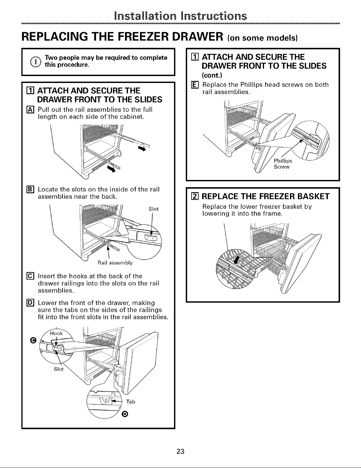
REPLACING THE FREEZER DRAWER (on some models)
o Two people may be required to complete
I
this procedure.
[] ATTACH AND SECURE THE
DRAWER FRONT TO THE SLIDES
[] Pull out the rail assemblies to the full
length on each side of the cabinet.
[] Locate the slots on the inside of the rail
assemblies near the back.
Slot
[] ATTACH AND SECURE THE
DRAWER FRONT TO THE SLIDES
(cont.)
[] Replace the Phillips head screws on both
rail assemblies.
Phillips
Screw
[] REPLACE THE FREEZER BASKET
Replace the lower freezer basket by
lowering it into the frame.
Rail assembly
[] Insert the hooks at the back of the
drawer railings into the slots on the rail
assemblies.
[] Lower the front of the drawer, making
sure the tabs on the sides of the railings
fit into the front slots in the rail assemblies,
G
Slot
Tab
23

mnstaliation mnstructions
REVERSING THE DOOR SWING (Single Door Refrigerator Models only)
IMPORTANT NOTES
When reversing the door swing:
NOTE: Door swing is not reversible on some
stainless steel models.
• Read the instructions all the way through
before starting.
• Handle parts carefully to avoid scratching
paint.
• Set screws down by their related parts to
avoid using them in the wrong places.
• Provide a non-scratching work surface for
the doors,
IMPORTANT: Once you begin, do not move
the cabinet until door-swing reversal is
completed.
These instructions are for changing the
hinges from the right side to the left sideiif
you ever want to change the hinges back to
the right side, follow these same instructions
and reverse all references to left and right.
• Once door swing is finalized, ensure
the logo badge is properly aligned and
permanently secured to the door by
removing the adhesive cover on the back
side. NOTE: If necessary call Customer
Service for a replacement badge.
Unplug the refrigerator from its electrical
outlet.
Empty all door shelves, including the dairy
compartment.
[] REMOVE THE
REFRIGERATOR DOOR
[] Tape the door shut with masking tape.
[] Remove the hinge cover on top of the
refrigerator door by squeezing it and
pulling it up.
[] Using a 3/8" or 10 mm socket
ratchet/driver, remove the bolts securing
the top hinge to the cabinet. Then lift the
hinge straight up to free the hinge pin
from the socket in the top of the door.
O
Hinge Cover
J
y
y
TOOLS YOU WiLL NEED
Adjustable Wrench 3/8" and 10 mm Socket
Masking Tape
Phillips Screwdriver
Ratchet!Driver
Putty Knife or
Thin-blade Screwdriver
[]
Remove the tape and tilt the door away
from the cabinet. Lift the door off the
center hinge pin. Ensure that the white
hinge pin thimble remains on the hinge pin
or inside door hinge pin hole located in the
bottom of the door.
[] Set the door on a non-scratching surface
with the inside up.
24
Top Hinge
G

mnstaliation mnstructions
[] REMOVE THE CENTER HINGE PIN
[] On models with a freezer door, tape the
door shut with masking tape.
[] Using an adjustable wrench, remove the
center hinge pin.
[]
REMOVE THE FREEZER DOOR
(freezer door models)
[]
Remove the tape and tilt the door away
from the cabinet. Lift the door off the
bottom hinge pin.
NOTE: There is a plastic washer between
the hinge and the top of the freezer door.
Do not lose.
[] TRANSFER BOTTOM HINGE
BRACKET (freezer door models)
[] Remove the base grille by grasping it at
the bottom and pulling it straight out.
[] Using a 3/8" or 10 mm socket
ratchet/driver, remove the screws
securing the bottom hinge bracket to the
cabinet.
[] Using an adjustable wrench, remove the
hinge pin and washer(s) from the right
side of the bracket and install on the left.
(_ Washer(s)
j J-/
[] Set the door on a non-scratching surface
with the inside up.
[] REMOVE CENTER HINGE
Using a 3/8" or 10 mm socket
ratchet/driver and Phillips head
screwdriver, remove the bolts and screws
securing the center hinge to the cabinet.
Set hinge, bolts, screws, washer (on
freezer door models) and hinge pin aside.
On models with a freezer drawer, skip to
Step 7.
0
25

mnstaliation mnstructions
REVERSING THE DOOR SWING (cont.)
[] TRANSFER BOTTOM HINGE
BRACKET (freezer door models, cont.)
[] Install the bottom hinge bracket on the
left side of the cabinet.
jjj
[] Replace the base grille by aligning the
prongs on the back of the grille with the
holes in the cabinet. Push forward until
the grille snaps into place,
[] INSTALL CENTER HINGE
[] Transfer the plug button and screws in
the hinge holes on the left side to the
right side.
[] Install the center hinge on the left side.
[]
TRANSFER FREEZER DOOR STOP
(freezer door models)
Remove the door stop on right side of the
[]
bottom of the freezer door by removing
the two screws.
Move the plastic hinge hole thimble to the
[]
opposite hole.
Install the door stop on the left side.
[]
Bottom of Freezer Door
(Right Side)
Bottom of Freezer Door
(Left Side)
[] HANG THE FREEZER DOOR
(freezer door models)
Lower the freezer door onto the bottom
hinge pin, then shut the door, making
sure to align the door with the cabinet.
Make sure the gasket on the door is flush
against the cabinet.
26

mnstaliation mnstructions
[] INSTALL CENTER HINGE PIN
[] Install the center hinge pin.
NOTE: On models with a freezer door,
be sure to put the washer between the
top of the freezer door and the bottom
of the center hinge.
Freezer Door Models Freezer Drawer Models
TRANSFER REFRIGERATOR
@
DOOR STOP
[]
Remove the door stop on right side of
the bottom of the refrigerator door by
removing the two screws.
[]
Move the plastic hinge hole thimble to
the opposite hole.
[]
Install the door stop on the left side,
making sure to line up the screw holes
in the door stop with the holes in the
bottom of the door.
I-_ REHANG REFRIGERATOR DOOR
[] Lower the refrigerator door onto the
center hinge pin. Ensure that the white
hinge pin thimble is on the center hinge
pin or inside door hinge pin hole located
in the bottom of the door.
[]
Insert the top hinge pin into the hinge
hole on top of the refrigerator door. Make
sure the door is aligned with the cabinet.
Attach the hinge to the top of the cabinet
loosely with the bolts.
[]
Make sure the gasket on the door is
flush against the cabinet and is not
folded. Support the door on the handle
side and make sure the door is straight
and the gap between the doors is even
across the front. While holding the door
in place, tighten the top hinge bolts.
Replace the hinge cover.
Bottom of Bottom of
Refrigerator Door Refrigerator Door
(Right Side) (Left Side)
[] TRANSFER REFRIGERATOR
DOOR HANDLE TO RIGHT
Refer to Remove the Fresh Food Door
Handle and Attach the Fresh Food Door
Handle sections for instructions.
27

mnstaliation mnstructions
REMOVING THE DOORS (Double Door Refrigerator Models only)
IMPORTANT NOTES
NOTE: Door swing is not reversible.
• Read the instructions all the way through
before starting.
• Handle parts carefully to avoid scratching
paint.
• Set screws down by their related parts to
avoid using them in the wrong places.
• Provide a non-scratching work surface for
the doors.
IMPORTANT: Once you begin, do not move
the cabinet.
These instructions are for removing the
doors.
Unplug the refrigerator from its electrical
outlet.
Empty all door shelves, including the dairy
compartment.
TOOLS YOU WiLL NEED
Adjustable Wrench 3/8" and 10 mm Socket
Ratchet!Driver
[] REMOVE THE
REFRIGERATOR DOORS
[] Tape the doors shut with masking tape.
[] Remove the screw securing each hinge
cover, lift the hinge cover and place to
the side on top of the refrigerator.
Carefully disconnect the wire connector
and remove the screw securing the
ground wire.
Wire Hinge Cover
Connector
(appearance may vary)
[]
Using a 3/8" or 10 mm socket
ratchet/driver, remove the bolts securing
the top hinge to the cabinet. Then lift the
hinge straight up to free the hinge pin
from the hinge pin hole in the top of the
door. Carefully remove the wires from the
hinge pin through the slot.
Masking Tape Putty Knife or
Thin-blade Screwdriver
Phillips Screwdriver
PARTS INCLUDED
C Spacer (on some models)
JJ
_Top Hinge
(appearance may vary)
[]
Remove the tape and tilt the door away
from the cabinet. Lift the door off the
center hinge pin. Ensure that the white
hinge pin thimble remains on the center
hinge pin or inside door hinge pin hole
located in the bottom of the door.
[] Set the door on a non-scratching surface
with the inside up.
28
Hinge Pin
Thimble

mnstaliation mnstructions
[] REMOVE CENTER HINGE
Using a 3/8" or 10 mm socket
ratchet/driver and Phillips head
screwdriver, remove the bolts and screw
securing the center hinge to the cabinet.
Set hinge, bolts, and screw aside.
[] REMOVE OPPOSITE DOOR
Follow the same procedure on the
opposite door.
[] REMOVE FREEZER DRAWER
Refer to the Removing the Freezer Drawer
section for instructions.
29

mnstaliation mnstructions
REPLACING THE DOORS (Double Door Refrigerator Models only)
[] INSTALL CENTER HINGE
Install the center hinge on each side.
REHANG REFRIGERATOR DOORS
[]
[]
Lower the refrigerator door onto the
center hinge pin. Ensure that the white
hinge pin thimble is on the center hinge
pin or inside door hinge pin hole located
in the bottom of the door.
Thimble
Hinge Pin
[]
Securely tape the door shut with masking
tape or have a second person support
the door.
[]
Route wires through top hinge pin slot.
Insert the top hinge pin into the hinge hole
on top of the refrigerator door. Make sure
the door is aligned with the cabinet and
opposite door. Attach the hinge to the top
of the cabinet loosely with the bolts.
[]
REHANGREFRIGERATORDOORS(CONT.)
[]
Make sure the gasket on the door is
flush against the cabinet and is not folded.
Make sure the door is straight and the gap
between the doors is even across the front.
While holding the aligned door in place,
tighten the top hinge bolts. Replace the
hinge cover and screw.
Hinge Cover ---"_C'"'"_
\ ;: i"- j ,.,r.Y
TopHinoeBo,ts
(appearance may __
Y
[] REPLACE OPPOSITE DOOR
Follow the same procedure on the
opposite door.
[] ALIGN DOUBLE DOORS
If the top of the doors are uneven, first
try to raise the lowest door by turning the
leveling leg on the same side as the door
until the doors are even. If the unit rocks,
re-adjust the leveling legs to the extent
that the unit is stable.
Top Hing
Pin
(appearance
[] Reconnect the wire connector and
reconnect the ground wire using the screw
removed earlier. Ensure that the wire
connector is fully engaged.
IMPORTANT: The ground wire must be
reinstalled to ensure a proper ground.
Wire
Connector
If the doors remain uneven, use a C spacer
to align the doors. While lifting the door
on the hinge side with one hand, insert a
C spacer with pliers. Continue to add C
spacers until the doors are even,
Spacer
[] REPLACE FREEZER DRAWER
Refer to the Replacing the Freezer Drawer
section for instructions.
 Loading...