

Page 1
GE
Grid Solutions
MultiNet
Serial to Ethernet Converter
Instruction Manual
Firmware Revision 1.x
Manual P/N: 1601-0117-A4
GE Publication Number: GEK-106498C
*1601-0220-A4*
Page 2

Copyright © 2017 GE Multilin Inc. All rights reserved.
The contents of this manual are the property of GE Multilin Inc. This documentation is
furnished on license and may not be reproduced in whole or in part without the permission
of GE Multilin. The content of this manual is for informational use only and is subject to
change without notice.
Part number: 1601-0117-A4 (July 2017)
For product support, contact the information and call center as follows:
GE Grid Solutions
650 Markland Street
Markham, Ontario
Canada L6C 0M1
Worldwide telephone: +1 905 927 7070
Europe/Middle East/Africa telephone: +34 94 485 88 54
North America toll-free: 1 800 547 8629
Fax: +1 905 927 5098
Worldwide e-mail:
Europe e-mail:
Website:
multilin.tech.euro@ge.com
http://www.gegridsolutions.com/multilin
multilin.tech@ge.com
Page 3

TOC TABLE OF CONTENTS
Table of Contents
FEATURES ..............................................................................................................................................1
DESCRIPTION .......................................................................................................................................2
RS485 SERIAL PORT ..........................................................................................................................3
10BASE-F FIBER OPTIC PORT ........................................................................................................4
INPUT POWER TERMINALS ............................................................................................................5
MOUNTING ...........................................................................................................................................6
GETTING STARTED WITH ENERVISTA TO SETUP MULTINET ............................................7
CONFIGURATION ...............................................................................................................................10
EXAMPLE: CONNECTING MULTINET TO A PQM ............................................................12
EXAMPLE: CONFIGURING A LAPTOP TO COMMUNICATE TO MULTINET OVER CROSSOVER
CABLE. ................................................................................................................15
DIMENSIONS ........................................................................................................................................17
ORDER CODE .......................................................................................................................................18
SPECIFICATIONS .................................................................................................................................19
WARRANTY ...........................................................................................................................................21
MULTINET SERIAL TO ETHERNET CONVERTER – INSTRUCTION MANUAL TOC–I
Page 4

TABLE OF CONTENTS
TOC–II MULTINET SERIAL TO ETHERNET CONVERTER – INSTRUCTION MANUAL
Page 5

GE
Grid Solutions
1. Features
MultiNet
Serial to Ethernet Converter
Instruction Manual
Instruction Manual
• Converts Modbus® RTU over RS485 into Modbus® TCP/IP over Ethernet.
• Supports both 10BaseT Ethernet and 10BaseF fiber connections.
• Connect up to 32 RS485 serial devices to an Ethernet network.
• Modbus
communicate to the same IED.
• The Multinet-FE is specifically designed for use with the PQMII and other GE serial
Modbus IEDs and deployed for use in an Electrical utility or Substation as part of a
Large Scale Fixed Installation (LSFI).
• Simple "plug and play" device setup with EnerVista software.
®
TCP/IP allows multiple SCADA masters to simultaneously connect and
MULTINET SERIAL TO ETHERNET CONVERTER – INSTRUCTION MANUAL 1
Page 6
INSTRUCTION MANUAL
2. Description
The MultiNet Serial-to-Ethernet converter is a communications module that provides GE
Multilin serial Modbus IEDs with Modbus TCP/IP communications over Ethernet. MultiNet
has the capability to connect up to 32 serial Modbus devices, eliminating complex wiring
and additional communications converters, as well as providing a streamlined and
economical Ethernet hub. Unlike most communications converters designed for
commercial use, MultiNet is environmentally hardened to withstand severe utility and
industrial conditions.
MultiNet can be used to connect an existing Modbus RTU network over RS485 onto a LAN
in order to support multiple SCADA masters or advanced HMI systems. Additionally, the
use of MultiNet greatly facilitates the setup and wiring of any serial device to a
communications center since it avoids costly RS485 cable runs. Finally, large RS485
networks are slow and have a typical limit of 32 devices. MultiNet allows customers to
expand that limit as well as improving network performance by separating large RS485
networks into smaller groups.
2 MULTINET SERIAL TO ETHERNET CONVERTER – INSTRUCTION MANUAL
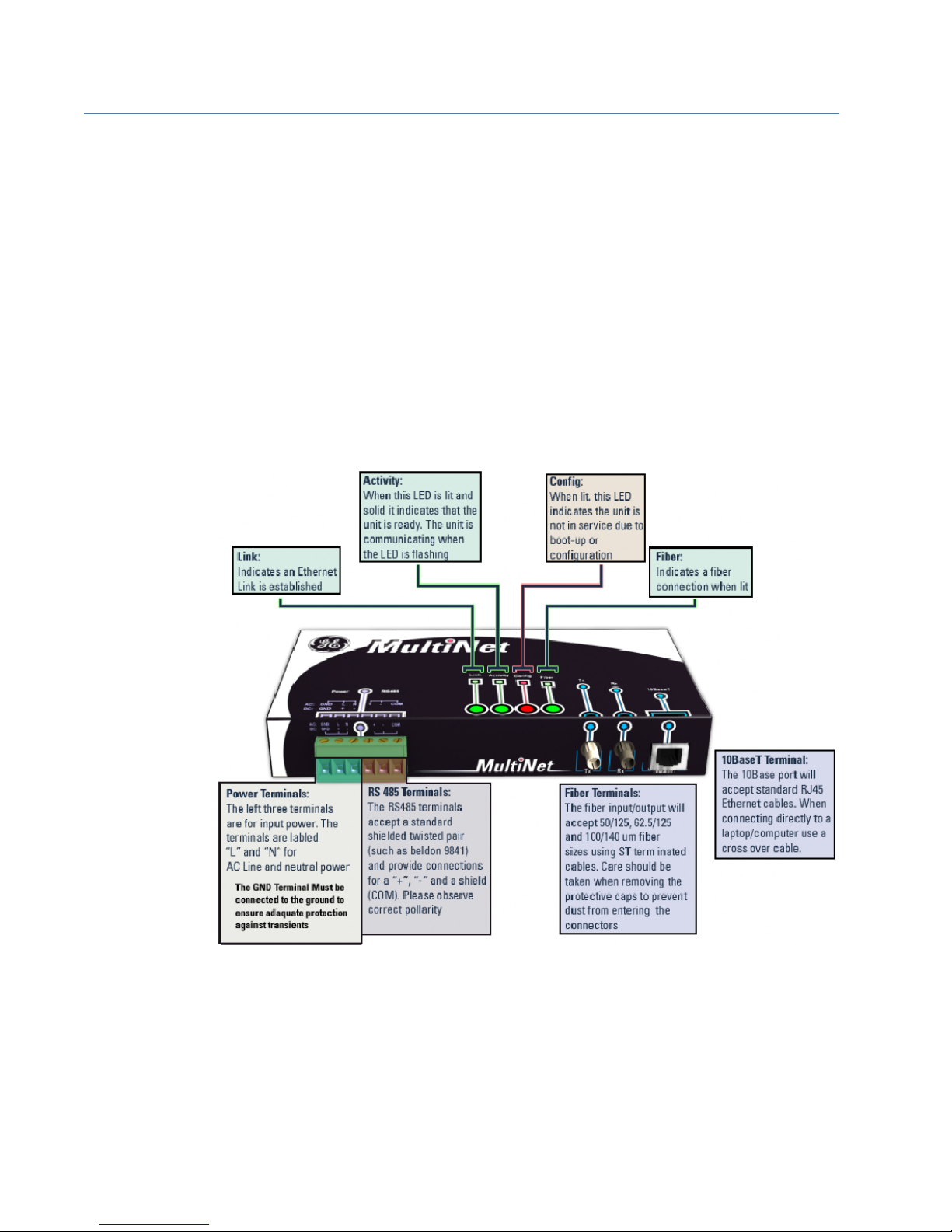
FIGURE –1: Connections
Page 7

3. RS485 Serial Port
RS485 data transmission and reception is accomplished over a single twisted pair with
transmit and receive data alternating over the same two wires. Using this port, continuous
monitoring and control to a PLC, protection relay or any serial Modbus IED is possible.
Connect the “+”, “–“ and common terminal of MultiNet to the “+”, “–“ and common terminals
of all the IEDs. Correct polarity must also be observed. For instance, the IEDs must be
connected with all RS485 “+” terminals connected together, and all RS485 “–” terminals
connected together.
To minimize errors from noise, the use of shielded twisted pair wire is recommended. The
COM terminal should be connected to the common wire inside the shield, when provided.
To avoid loop currents, the shield should be grounded at one point only. Each relay should
also be daisy-chained to the next relay in the link. A maximum of 32 relays can be
connected in this manner without exceeding driver capability.
Lightning strikes and ground surge currents can cause large momentary voltage
differences between remote ends of the communication link. For this reason, surge
protection devices are internally provided at the communication port. An isolated power
supply with an opto-coupled data interface also acts to reduce noise coupling. To ensure
maximum reliability, all equipment should have similar transient protection devices
installed.
INSTRUCTION MANUAL
Note
NOTE
Both ends of the RS485 circuit can be terminated with impedance as shown in Figure 2:
Typical Configuration. Termination networks should only be applied if long cable runs
are used between RS485 connections. A typical load value for a terminating network is a
120-ohm resistor in series with a 100-pF capacitor.
The termination capacitors are used for AC termination to reduce the power consumption
of the idle link, as well as to reduce the ringing voltage. The negative effect is a reduction in
cable length and bit rate. Termination capacitor values are dependent on various factors,
including the number of Unit Loads, network data rate, and cable length. The termination
capacitor value provided in the instruction manual should be taken as a guideline only. In
order to determine the optimum capacitor value factors, such as number of devices
connected on the network, network speed, physical media, and network cable length
should be considered.
MULTINET SERIAL TO ETHERNET CONVERTER – INSTRUCTION MANUAL 3
Page 8

INSTRUCTION MANUAL
4. 10BASE-F Fiber Optic Port
The fiber optic communications port allows for fast and efficient communications with
Modbus TCP/IP at 10 Mbps. Fiber optic transmissions provide an ideal solution for areas
where RS485 communications or Ethernet via a twisted pair have traditionally caused
problems. Fiber is immune to electrical interference and provides complete isolation.
Optical fibers may be connected to the MultiNet supporting a wavelength of 820 nm in
multimode. Optical fiber is only available with the MultiNet-FE option (see the Order Code
for details). The MultiNet-FE has a 10BaseF transmitter/receiver for optical fiber
communications and supports optical fiber sizes of 50/125 μm, 62.5/125 μm, and 100/140
μm. The fiber optic port is designed such that the response times will not vary for any core
100 μm or less in diameter. For optical power budgeting, splices are required every 1 km
for the transmitter/receiver pair (the ST type connector contributes for a connector loss of
0.2 dB). When splicing optical fibers, the diameter and numerical aperture of each fiber
must be the same. Only a quarter turn of the coupling is required to engage or disengage
the ST type connector.
The 10BaseT Ethernet port and the 10BaseF Fiber port are internally linked and should not
be used together.
Ensure the dust covers are installed when the fiber is not In use. Dirty or scratched
connectors can lead to high losses on a fiber link.
Observing any fiber transmitter output may cause injury to the eye!
4 MULTINET SERIAL TO ETHERNET CONVERTER – INSTRUCTION MANUAL
Page 9

5. Input Power Terminals
The input power terminals are located on the left side of the green terminal block. MultiNet
may be connected to either 90 to 265 V AC at 50/60 Hz or 90 to 300 V DC supply power.
The terminals are labeled "+" and "–" for DC positive and negative input power and "L" and
"N" are for AC line and neutral input power. The GND terminal must be connected to
ground to ensure adequate protection against transients.
Control power supplied to the MultiNet must be connected to the matching power supply
range. If the voltage is applied to the wrong terminals, damage may occur!
INSTRUCTION MANUAL
MULTINET SERIAL TO ETHERNET CONVERTER – INSTRUCTION MANUAL 5
Page 10

INSTRUCTION MANUAL
6. Mounting
MultiNet is DIN rail mountable and ships with two DIN rail clips attached on the rear of the
unit. The DIN rail clips can attach the unit onto a standard 35 mm DIN rail. Place the top
hooks of the clip against the DIN rail and apply a downward force until an audible click is
heard. In order to remove the unit, place a standard slotted screwdriver between the unit
and the DIN rail and apply an upward force.
Each clip is held onto the unit using a standard 4-40 Phillips head screw. If the DIN rail
option is not used, remove the DIN rail clips by unscrewing the six screws. Once the clips
have been removed re-screw the six screws back into their original positions. Do not
substitute screws, since the wrong length of screw may damage the internals of the
product and void the warranty.
6 MULTINET SERIAL TO ETHERNET CONVERTER – INSTRUCTION MANUAL
FIGURE –2: Typical Configurations
Page 11

7. Getting Started With EnerVista to Setup Multinet
The MultiNet setup software is provided to edit settings and configure the unit. The setup
software connects to the unit through either the 10BaseT (RJ45*) port or the 10BaseF
(fiber) port.
INSTRUCTION MANUAL
Note
NOTE
* Use a shielded RJ45 cable
The following requirements must be met to ensure correct operation of the MultiNet setup
software:
• Pentium class or higher processor (Pentium II 300 MHz or higher recommended)
• Windows 95, 98, 98SE, ME, NT 4.0 (Service Pack 4 or higher), 2000, XP
• 64 MB of RAM (256 MB recommended)
• 40 MB of available hard drive space (100 MB recommended)
• Video capable of displaying 800 600 or higher in High Color mode (16-bit color)
• An Ethernet communications port.
To download MulitNet directly, go to
http://www.GEmultilin.com
To download MulitNet through enerVista (suggested), follow the procedure outlined below.
1. Download EnerVista
• From the Web:
i Direct your web browser to the enerVista website at
http://
www.enerVista.com. Click on the “Downlaod Now” button.
ii Run the enerVista installation program and follow the on-screen instructions.
• From the EnerVista CD:
i Insert the enerVista CD into your computer’s CD drive and it will automatically
open the welcome page. Click on the “Install Now” button.
ii Run the enerVista installation program and follow the on-screen instructions.
MULTINET SERIAL TO ETHERNET CONVERTER – INSTRUCTION MANUAL 7
Page 12

INSTRUCTION MANUAL
.
2. Setup the MultiNet Software:
i On the main enerVista page, select “IED SetUp” from the LaunchPad window.
ii Click on the “Install Software” button at the top of the screen.
iii Select MultiNet from the product list. Indicate whether you are installing the
software from CD or the Web, then click “Check Now”.
iv Check off the MultiNet Setup program from the Downloads screen and click
“Download Now”.
v Once the download is complete, the MutiNet installation file will be shown on
screen. Double-click this file to run the installation program.
vi Run the installation program and follow the on-screen instructions.
vii Once the installation is complete, click on “IED Setup” on the left panel of the
screen. You will see a Multinet icon on the IED screen. Double click on it to
launch the MulitNet setup application.
8 MULTINET SERIAL TO ETHERNET CONVERTER – INSTRUCTION MANUAL
Page 13

INSTRUCTION MANUAL
MULTINET SERIAL TO ETHERNET CONVERTER – INSTRUCTION MANUAL 9
Page 14

INSTRUCTION MANUAL
8. Configuration
Before starting, verify that the Ethernet network cable is properly connected to the
Ethernet port on MultiNet. To connect MultiNet directly to the Ethernet port of a PC or
laptop, use a crossover cable; to connect MultiNet directly to an Ethernet network, use a
regular pass-through RJ-45 cable.
To setup MultiNet for Ethernet communications use the following procedure:
1. Install and start the latest version of the MultiNet Setup software (available from the
GE Multilin Products CD or online from
section: Getting Started with MultiNet Software).
http://www.GEmultilin.com . See the previous
2. Select the Communications > Device Setup menu item to open the Device Setup
window.
3. The left pane shows the currently configured MultiNet Devices. Click the Add Device
button to add a new MultiNet device to the device list.
4. Enter the desired name in the Device Name field and a description (optional) of the
device.
10 MULTINET SERIAL TO ETHERNET CONVERTER – INSTRUCTION MANUAL
FIGURE –3: MultiNet Setup Software Main Screen
Page 15

INSTRUCTION MANUAL
5. The MAC address is used to identify and configure the unit. Fill in the MAC address
field with the address found on the back of MultiNet (for example, 00-20-4A-62-AE-66).
FIGURE –4: Device Setup Screen
6. Under network settings, enter the IP address, Subnet and Gateway of the MultiNet
network interface. If these values are not known, consult your network administrator.
7. Under port settings, enter the Baud Rate and Parity bit for the MultiNet serial
interface.
8. Once the serial and network settings have been entered, click [SAVE] to save the
changes. The message “success saving settings to MultiNet device” will appear in the
status window when complete. Additional devices may be added to the list by
following the same procedure.
9. Click [OK] to close the device setup screen.
MULTINET SERIAL TO ETHERNET CONVERTER – INSTRUCTION MANUAL 11
Page 16

INSTRUCTION MANUAL
8.1 EXAMPLE: Connecting MultiNet to a PQM
The following steps detail how to use MultiNet in order to connect a PQM to an Ethernet
network.
1. Wire COM1 on the back of the PQM to the RS485 terminals on MultiNet. The wiring is
detailed in Figure 2: Typical Configuration. Since for this example short cable runs are
used, terminators are not necessary.
2. Check the settings within the PQM, noting the Baud rate, Parity Bit and Slave Address.
For the sake of this example the values of 19200, none (or N), and 254 will be used for
the baud rate, parity bit, and slave address respectively.
3. Note the MAC address of the MultiNet unit. For this example, a MAC address of 00-20-
4A-62-AE-00 will be used. The MAC address is located on the rear of the unit.
4. Connect MultiNet to the network LAN. Consult your IT administrator to determine a
suitable IP address, subnet, and gateway setting for the unit . For this example we will
use 192.168.1.2 as the IP address, 255.255.255.0 as the Subnet and 192.168.1.1 as
the Gateway.
5. Open the MultiNet setup software. Use the procedure detailed in the Configuration
section to configure the unit. For this example the following settings will be used:
Note
Device Name: MultiNet 1
IP Address: 192.168.1.2
Subnet: 255.255.255.0
Gateway: 192.168.1.1
Baud Rate: 19200
Parity Bit: None
The baud rate and parity bit are identical to those set within the PQM. Additionally, the
MAC address from step 3 is needed to configure the Network settings.
NOTE
6. Close the MultiNet setup software and open enerVista Viewpoint.
7. From the main screen of enerVista Viewpoint, click Device Setup to open the Device
Setup window.
12 MULTINET SERIAL TO ETHERNET CONVERTER – INSTRUCTION MANUAL
Page 17

INSTRUCTION MANUAL
FIGURE –5: Device Setup Screen within Viewpoint
8. On the left is the device list showing the “Quick Connect” default site. Click on the plus
sign next to the “Quick Connect” site to reveal the “Quick Connect” default device.
Selecting this device allows parameters to be entered in the right pane.
9. For this example, we are going to configure the “Quick Connect” device as our PQM.
Select Ethernet as the interface and fill in the IP address and slave address of the PQM.
10. Click Read Order Code. Viewpoint will locate the PQM device and connect to it. Once
this order code has been read, click OK to save the configuration.
11. Select the Plug & Play > Create Schema menu item to open the Plug and Play Device
dialog box. Ensure that “PQM” is selected within the drop down selection. Click Create
to automatically create plug and play screens for the PQM.
MULTINET SERIAL TO ETHERNET CONVERTER – INSTRUCTION MANUAL 13
Page 18

INSTRUCTION MANUAL
FIGURE –6: Dialog Box for Creating “plug and play” Screens
12. When finished, the plug and play menu will appear, showing our PQM labeled as
Quick Connect. Click the Dashboard button below the PQM icon to view the device
information. We have now successfully accessed our PQM through MultiNet.
14 MULTINET SERIAL TO ETHERNET CONVERTER – INSTRUCTION MANUAL
FIGURE –7: Plug and Play Menu Showing Attached PQM.
Page 19

INSTRUCTION MANUAL
8.2 EXAMPLE: Configuring a Laptop to Communicate to MultiNet over Crossover Cable.
This procedure details how to configure MultiNet for use with a crossover cable. Using a
crossover cable allows for a direct local connection to a MultiNet device, bypassing the
network. The following procedure is based upon the Windows 2000 operating system;
variations of this procedure will work other windows operating systems, as they are all
fairly similar.
Note
This example uses sample values for IP address, subnet and gateway. Please substitute
these values with your own
NOTE
1. Connect a CAT5 crossover Ethernet cable between the laptop running the MultiNet
setup software and the MultiNet unit. Since the 10BaseT connection is being used, the
10BaseF connection must be disconnected.
2. Right click on My Network Places and select properties from the pop down menu.
3. Click on the Local Area Connection icon and select properties.
4. Select Internet Protocol (TCP/IP) and click Properties.
5. Record the current settings of the Internet Protocol (TCP/IP) properties window.
6. Select the Use the following IP address button. The Multinet IP address must be
assigned as the gateway address of the laptop. For example, if an IP address of
192.168.1.2 has been assigned to the MultiNet, use that address as the gateway for
the laptop. Similarly, set the IP address of the laptop to the gateway IP of the MultiNet.
For example, set the laptop IP address to “192.168.1.1” if the gateway IP of the
MultiNet is “192.168.1.1”. The subnet mask is to remain the same. Fill in the
corresponding fields – refer to the table below:
Laptop Multinet
IP Address 192.168.1.1 192.168.1.2
Gateway Address 192.168.1.2 192.168.1.1
Subnet 255.255.255.0 255.255.255.0
Note
The laptop has been configured as the gateway for MultiNet – do not connect the laptop
back to the network without first restoring the settings for the IP address. Again, the IP
NOTE
address, Subnet and gateway supplied here are for this example only. Please change
these values so that they correspond to the values assigned in your network.
7. Click OK to save the changes. Depending on your operating system, you may wish to
restart your PC.
MULTINET SERIAL TO ETHERNET CONVERTER – INSTRUCTION MANUAL 15
Page 20

INSTRUCTION MANUAL
FIGURE –8: Setting the IP Address on a Laptop.
8. Open the MultiNet setup program and follow the procedure detailed within the
CONFIGURATION section. For this example use the IP address of 192.168.1.2, subnet
of 255.255.255.0 and a gateway of 192.168.1.1.
9. Once the configuration of the MultiNet device is complete, return the laptop to its
previous settings using the recorded values from step 5. If the MultiNet device was
configured properly, communications may be tested on the connected network using
EnerVista, as shown in the first example.
16 MULTINET SERIAL TO ETHERNET CONVERTER – INSTRUCTION MANUAL
Page 21

9. Dimensions
INSTRUCTION MANUAL
MULTINET SERIAL TO ETHERNET CONVERTER – INSTRUCTION MANUAL 17
FIGURE –9: MultiNet Dimensions
Page 22

INSTRUCTION MANUAL
10. Order Code
Multinet * Modbus RTU to Modbus TCP/IP converter with RS485 communications
FE 10BaseT Ethernet Port, and 10BaseF fiber optic port
18 MULTINET SERIAL TO ETHERNET CONVERTER – INSTRUCTION MANUAL
Page 23

11. Specifications
INSTRUCTION MANUAL
ETHERNET
Version 2.0/IEEE 802.3
10BaseT: ....................................................................................................RJ45 connection*
10BaseF: .....................................................................................................820 nm, multi-mode, fiber optic with
ST connector
Modbus
®
TCP/IP
Note
NOTE
* Use a shielded RJ45 cable.
RS485 PORT
RS485 2-wire, half duplex, isolated
Baud Rate: ................................................................................................300 bps to 115.2 Kbps
Protocol: .....................................................................................................Modbus
®
RTU
INSTALLATION
Configuration through EnerVista Setup software
POWER INPUT
AC power: ..................................................................................................100 to 240 V AC (±10%) at 50/60 Hz,
20 VA max
Minimum/Maximum AC voltage: 90
VAC / 264 VAC
DC power: .................................................................................................90 to 300 V DC, 5 W max.
MECHANICAL SPECIFICATIONS
Material: .....................................................................................................Metal enclosure
Dimensions: .............................................................................................6.6” 3.98” 1.46”
Shipping box: ...........................................................................................12.9” 9” 3.25”
Ship weight: .............................................................................................2 lbs.
TYPE TESTS
TEST REFERENCE STANDARD TEST LEVEL
Dielectric voltage withstand EN60255-27 2300VAC
Impulse voltage withstand EN60255-27 5KV
Insulation resistance EN60255-27 500VDC >100Mohm
Electrostatic Discharge IEC61000-4-2 Level 4
RF immunity IEC61000-4-3 20V/m 80-1GHz
Fast Transient Disturbance IEC61000-4-4 Class A and B
Surge Immunity IEC61000-4-5 2KV & 1KV
Conducted RF Immunity IEC61000-4-6 10Vrms
Radiated & Conducted Emissions CISPR11 /CISPR22/ IEC60255-25 Class A
Power magnetic Immunity IEC61000-4-8 Level 5
Pulsed Magnetic Immunity IEC61000-4-9 1000A/m
Damped Oscillatory magnetic IEC61000-4-10 100A/m
Voltage Dip & interruption IEC61000-4-11
0,40,70,80% dips, 250/
300 cycle interrupts
Damped Oscillatory IEC61000-4-18/IEEEC37.90.1 2.5KV / 1MHz
MULTINET SERIAL TO ETHERNET CONVERTER – INSTRUCTION MANUAL 19
Page 24

INSTRUCTION MANUAL
Ingress Protection IEC60529
IP10 Front , IP40
remaining sides
APPROVALS
Applicable Council Directive: According to:
Low voltage directive EN60255-27
CE compliance
EMC Directive
EN61000-6-2
EN61000-6-4
UL508
cULus e83849 - vol 1 section 10
North America
(AC power only, DC sources
C22.2.No 14
pending)
ISO Manufactured under a ISO 9001 registered program
ENVIRONMENTAL
Ambient temperatures
Operating range: -20°C to 70°C
Altitude: 2000m (max)
Insulation Class: 1
Pollution Degree: II
Overvoltage Category: II
Ingress protection:
IP10 Front
IP40 top,bottom,back, left/right
20 MULTINET SERIAL TO ETHERNET CONVERTER – INSTRUCTION MANUAL
Page 25

12. Warranty
INSTRUCTION MANUAL
For products shipped as of 1 October 2013, GE warrants most of its GE manufactured
products for 10 years. For warranty details including any limitations and disclaimers, see
the Terms and Conditions at
https://www.gegridsolutions.com/multilin/warranty.htm
For products shipped before 1 October 2013, the standard 24-month warranty applies.
MULTINET SERIAL TO ETHERNET CONVERTER – INSTRUCTION MANUAL 21
Page 26

INSTRUCTION MANUAL
22 MULTINET SERIAL TO ETHERNET CONVERTER – INSTRUCTION MANUAL
 Loading...