

Page 1

LISTED
52TL
IND.CONT. EQ.
E83849
GE
Grid Solutions
MM300
Motor Management System
MM300 Revision: 1.6x
Manual P/N: 1601-9022-AC
Manual Order Code: GEK-113336L
Quick Start Guide
*1601-9022-AC*
Page 2

© 2016 GE Multilin Inc. All rights reserved.
The MM300 Motor Management System QuickStart Guide for revision 1.6x.
MM300 Motor Management System, EnerVista, EnerVista Launchpad, and EnerVista
MM300 Setup are registered trademarks of GE Multilin Inc.
The contents of this manual are the property of GE Multilin Inc. This documentation is
furnished on license and may not be reproduced in whole or in part without the permission
of GE Multilin Inc. The content of this manual is for informational use only and is subject to
change without notice.
Part number: 1601-9022-AC (April 2016)
Page 3

Storage
Store the unit indoors in a cool, dry place. If possible, store in the original packaging. Follow
the storage temperature range outlined in the Specifications.
To avoid deterioration of electrolytic capacitors, power up units that are stored in a deenergized state once per year, for one hour continuously.
Warranty
For products shipped as of 1 October 2013, GE warrants most of its GE manufactured
products for 10 years. For warranty details including any limitations and disclaimers, see
our Terms and Conditions at
For products shipped before 1 October 2013, the standard 24-month warranty applies.
https://www.gegridsolutions.com/multilin/warranty.htm
Repairs
The firmware and software can be upgraded without return of the device to the factory.
For issues not solved by troubleshooting, the process to return the device to the factory for
repair is as follows:
• Contact a GE Grid Solutions Technical Support Center. Contact information is found in
the first chapter.
• Obtain a Return Materials Authorization (RMA) number from the Technical Support
Center.
• Verify that the RMA and Commercial Invoice received have the correct information.
• Tightly pack the unit in a box with bubble wrap, foam material, or styrofoam inserts or
packaging peanuts to cushion the item(s). You may also use double boxing whereby
you place the box in a larger box that contains at least 5 cm of cushioning material.
• Ship the unit by courier or freight forwarder, along with the Commercial Invoice and
RMA, to the factory.
Customers are responsible for shipping costs to the factory, regardless of whether the
unit is under warranty.
• Fax a copy of the shipping information to the GE Grid Solutions service department .
Use the detailed return procedure outlined at
https://www.gegridsolutions.com/multilin/support/ret_proc.htm
The current warranty and return information are outlined at
https://www.gegridsolutions.com/multilin/warranty.htm
This product cannot be disposed of as unsorted municipal waste in the European
Union. For proper recycling return this product to your supplier or a designated
collection point. For more information go to www.recyclethis.info.
Page 4

TABLE OF CONTENTS
Table of Contents
OVERVIEW
Cautions and Warnings ....................................................................................................................... 3
Safety words and definitions......................................................................................................................3
General Safety Precautions - MM300.....................................................................................................3
For Further Assistance..........................................................................................................................4
INSTALLATION
Mechanical installation ........................................................................................................................1
Dimensions..........................................................................................................................................................1
Product identification .....................................................................................................................................2
Mounting ..............................................................................................................................................................2
Electrical installation .............................................................................................................................6
Module and terminal identification..........................................................................................................7
Full-voltage non-reversing starter ...........................................................................................................8
RS485 connections..........................................................................................................................................9
Phase current inputs (IO_A module) ..................................................................................................... 10
Phase voltage inputs (IO_B module).....................................................................................................12
Type IO_C module connections..............................................................................................................14
Type IO_D module connections .............................................................................................................15
Type IO_E module connections.............................................................................................................. 16
RTD sensor connections (IO_G module).............................................................................................. 16
Maintenance ...........................................................................................................................................17
In-service maintenance ............................................................................................................................. 17
Out-of-service maintenance....................................................................................................................18
Unscheduled maintenance (system interruption) ......................................................................... 18
Interfacing with the MM300.............................................................................................................18
MM300 graphical display pages............................................................................................................ 18
Introduction to the graphical control panel .....................................................................................20
Basic control panel....................................................................................................................................... 24
EnerVista MM300 Setup Software.................................................................................................25
Software requirements............................................................................................................................... 25
Troubleshooting the USB driver.............................................................................................................. 25
Installing the EnerVista MM300 Setup software............................................................................. 28
Upgrading the software.............................................................................................................................32
Connecting EnerVista MM300 Setup to the relay .................................................................32
Configuring serial communications ..................................................................................................... 32
Using the Quick Connect feature........................................................................................................... 33
Connecting to the relay.............................................................................................................................. 34
Working with setpoints and setpoint files.................................................................................35
Engaging a device......................................................................................................................................... 35
Entering setpoints .........................................................................................................................................35
File support....................................................................................................................................................... 36
Using setpoints files ..................................................................................................................................... 36
Downloading and saving setpoints files............................................................................................. 37
Adding setpoints files to the environment.........................................................................................37
Loading setpoints from a file ...................................................................................................................38
Uninstalling files and clearing data ...................................................................................................... 39
Upgrading relay firmware................................................................................................................39
Loading new relay firmware.................................................................................................................... 39
MM300 MOTOR MANAGEMENT SYSTEM – QUICKSTART GUIDE i
Page 5

TABLE OF CONTENTS
ACTUAL VALUES
Actual values overview .........................................................................................................................1
SETPOINTS
Understanding setpoints......................................................................................................................1
Configuration setpoints ........................................................................................................................2
Motor setpoints................................................................................................................................................. 2
Current and voltage transformers........................................................................................................... 6
PROTECTION ELEMENTS
Thermal protection .................................................................................................................................1
Overload curve.................................................................................................................................................. 1
COMMUNICATIONS
Communications interfaces ...............................................................................................................1
SPECIFICATIONS
Protection specifications......................................................................................................................1
User interface specifications..............................................................................................................3
Metering and monitoring specifications.......................................................................................3
Control specifications............................................................................................................................4
Inputs specifications ..............................................................................................................................4
Outputs specifications...........................................................................................................................5
Power supply specifications...............................................................................................................6
Communications specifications .......................................................................................................6
Testing and certification.......................................................................................................................7
Physical specifications..........................................................................................................................8
Environmental specifications.............................................................................................................8
MM300 ORDER CODES
Example of an MM300 order code ..................................................................................................2
ii MM300 MOTOR MANAGEMENT SYSTEM – QUICKSTART GUIDE
Page 6

GE
Grid Solutions
MM300 Motor Management System
Chapter 1: Overview
Overview
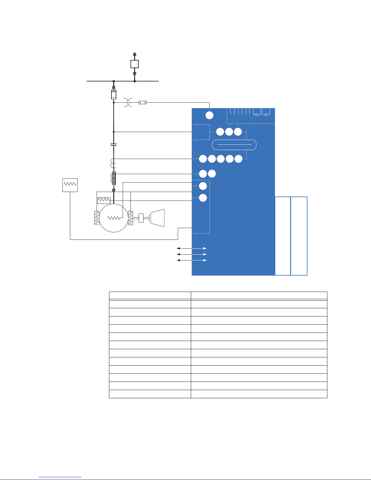
The MM300 is a modular motor protection and control system designed specifically for
low-voltage motor applications. The MM300 provides the following key benefits.
• Flexible protection, control, and communication options to suit any low-voltage motor
application.
• Small footprint designed specifically for IEC and NEMA MCC applications.
• Modular design reduces the number of spare components for maintenance and
testing.
• Integrated pushbuttons and LED indicators reduce external components and wiring.
• DIN rail and Panel Mounting.
• Multiple, simultaneous communication protocols allows simple integration into
monitoring and control systems.
• Optional basic control panel or graphical control panel interface provides local control
and access to system information.
• Automation FlexLogic™ for applications requiring more complex starter control, or
multi-starter scenarios with interlocking or programmable logic control.
MM300 MOTOR MANAGEMENT SYSTEM – QUICKSTART GUIDE 1
Page 7
CHAPTER 1: OVERVIEW
RS485 - Modbus RTU
Ethernet - Modbus TCP/IP
Profibus/DeviceNet
52
27
59 47
METERING
V, A, W, va r, VA , PF, Hz
27X
51R
49
37
66 46
50G
51G
49
MOTOR
LOAD
Stator RTDs
Bearing RTDs
Phase CT 3
Ground CT 1
Power Fuse
BUS
MM300
MOTOR MANAGEMENT SYSTEM
Temperature
Thermistor
Control PT
Contactor
Control
fuse
Direct voltage inputs
(690 V AC maximum)
Ambient air
RTD
Expansion module,
two cards per module,
maximum of two modules
38
Optional
three-phase
voltage
card
Options:
Six inputs & two form-A outputs (max 5 cards)
?
?
Three-phase voltage card (max 1 card)
Options:
Three RTDs - 100 ohm Platinum (max 2 cards)
?
?
Four form-C contact outputs (max 4 cards)
853739A2.CDR
Six inputs and two outputs (standard)
Optional RTD card
Table 1-1: MM300 protection functions
ANSI device Description
27X Undervoltage, auxiliary input
27 Undervoltage, three-phase
37 Undercurrent and underpower
38 Bearing temperature RTD
46 Current unbalance
47 Voltage phase reversal
49 Thermal overload
50G Ground instantaneous overcurrent
51G Ground time overcurrent
51R Locked/stalled rotor, mechanical jam
59 Overvoltage, three-phase
66 Starts per hour and time between starts
2 MM300 MOTOR MANAGEMENT SYSTEM – QUICKSTART GUIDE
Page 8
CHAPTER 1: OVERVIEW CAUTIONS AND WARNINGS
NOTE
Cautions and Warnings
Before attempting to install or use the device, review all safety indicators in this document
to help prevent injury, equipment damage, or downtime.
Safety words and definitions
The following symbols used in this document indicate the following conditions
DANGER:
Indicates a hazardous situation which, if not avoided, will result in death or serious
injury.
IMPORTANT:
CAUTION:
NOTE:
CAUTION:
Indicates a hazardous situation which, if not avoided, could result in death or serious
injury.
Indicates a hazardous situation which, if not avoided, could result in minor or
moderate injury.
Indicates practices not related to personal injury.
General Safety Precautions - MM300
Failure to observe and follow the instructions provided in the equipment manual(s)
could cause irreversible damage to the equipment and could lead to property damage,
personal injury and/or death.
Before attempting to use the equipment, it is important that all danger and caution
indicators are reviewed.
If the equipment is used in a manner not specified by the manufacturer or functions
abnormally, proceed with caution. Otherwise, the protection provided by the
equipment may be impaired and can result in Impaired operation and injury.
Caution: Hazardous voltages can cause shock, burns or death.
Installation/service personnel must be familiar with general device test practices,
electrical awareness and safety precautions must be followed.
Before performing visual inspections, tests, or periodic maintenance on this device or
associated circuits, isolate or disconnect all hazardous live circuits and sources of
electric power.
Failure to shut equipment off prior to removing the power connections could expose
you to dangerous voltages causing injury or death.
All recommended equipment that should be grounded and must have a reliable and
un-compromised grounding path for safety purposes, protection against
electromagnetic interference and proper device operation.
Equipment grounds should be bonded together and connected to the facility’s main
ground system for primary power.
Keep all ground leads as short as possible.
MM300 MOTOR MANAGEMENT SYSTEM – QUICKSTART GUIDE 3
Page 9

FOR FURTHER ASSISTANCE CHAPTER 1: OVERVIEW
At all times, equipment ground terminal must be grounded during device operation
and service.
In addition to the safety precautions mentioned all electrical connections made must
respect the applicable local jurisdiction electrical code.
Before working on CTs, they must be short-circuited.
For Further Assistance
For product support, contact the information and call center as follows:
GE Grid Solutions
650 Markland Street
Markham, Ontario
Canada L6C 0M1
Worldwide telephone: +1 905 927 7070
Europe/Middle East/Africa telephone: +34 94 485 88 54
North America toll-free: 1 800 547 8629
Fax: +1 905 927 5098
Worldwide e-mail: [email protected]
Europe e-mail: [email protected]
Website: http://www.gegridsolutions.com/multilin
4 MM300 MOTOR MANAGEMENT SYSTEM – QUICKSTART GUIDE
Page 10

GE
Grid Solutions
MM300 Motor Management System
Chapter 2: Installation
Mechanical installation
Installation
This section describes the mechanical installation of the MM300 system, including
dimensions for mounting and information on module withdrawal and insertion.
Dimensions
The MM300 is packaged in a modular arrangement.
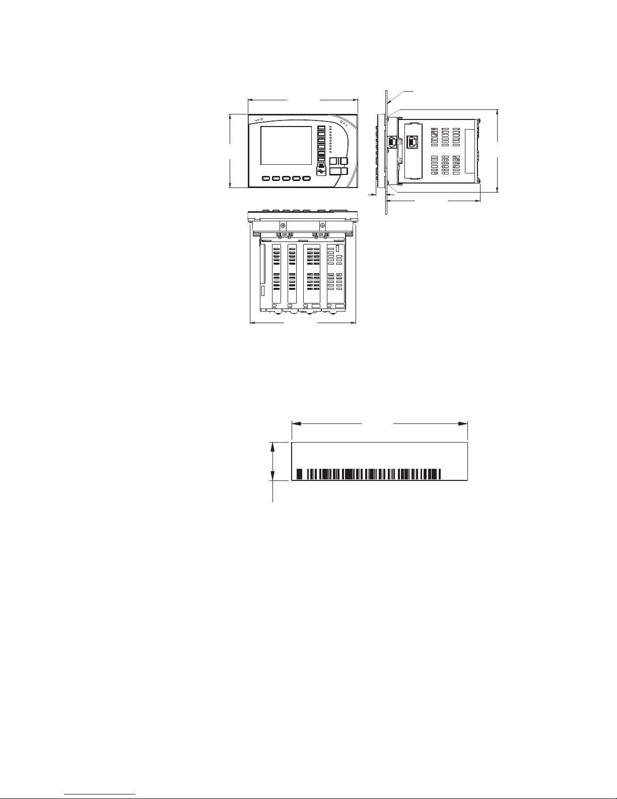
The dimensions of the MM300 are shown below. Additional dimensions for mounting and
panel cutouts are shown in the following sections.
MM300 MOTOR MANAGEMENT SYSTEM – QUICKSTART GUIDE 1
Page 11
MECHANICAL INSTALLATION CHAPTER 2: INSTALLATION
6.071”
(154,15 mm)
4.059”
(103,09 mm)
0.565”
(14,35 mm)
5.228”
(132,78 mm)
3.746”
(95,15 mm)
5.550”
(140,97 mm)
853724A1.CDR
PANEL
2.425”
(61.6 mm)
0.525”
(13.3 mm)
853748A1.CDR
Model:
Serial Number:
Firmware:
Mfg. Date:
Figure 2-1: MM300 dimensions
Product identification
The product identification label is located on the side panel of the MM300. This label
indicates the product model, serial number, firmware revision, and date of manufacture.
Figure 2-2: MM300 label
Mounting
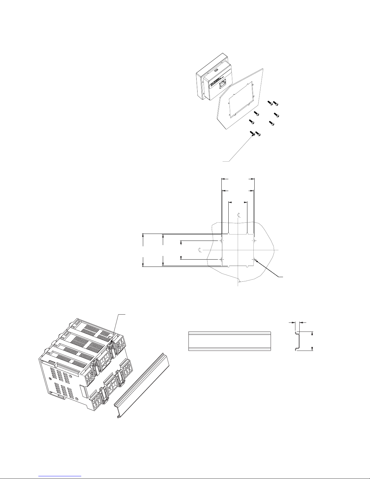
The MM300 can be mounted three ways: standard panel mount, DIN rail mount , and screw
mount for high vibration environments.
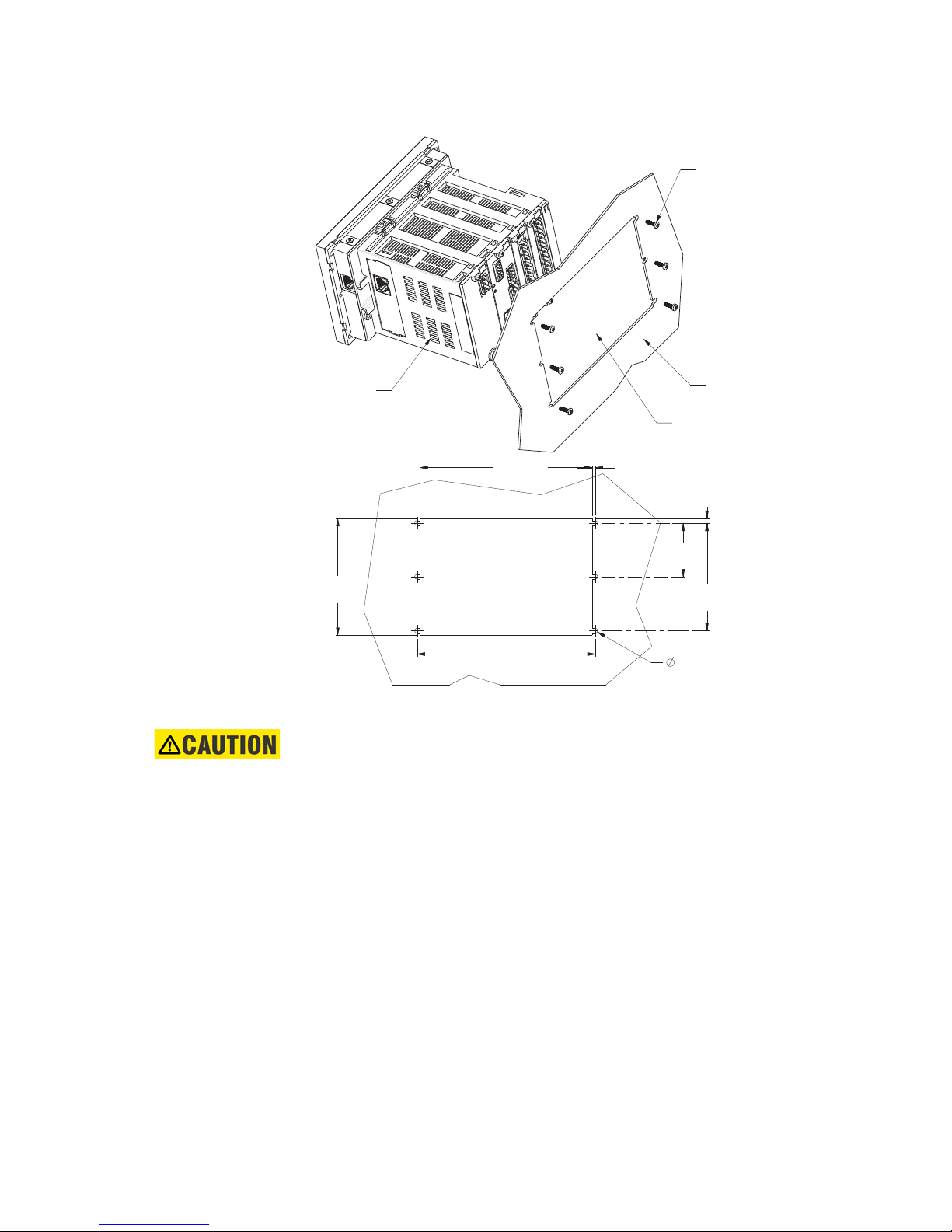
The standard panel mount and cutout dimensions are illustrated below.
2 MM300 MOTOR MANAGEMENT SYSTEM – QUICKSTART GUIDE
Page 12
CHAPTER 2: INSTALLATION MECHANICAL INSTALLATION
#4 - 40x3/8in SELF-TAP PAN HD PHILIPS
QTY: 6 (SUPPLIED); GE PART NO. 1402-0017
TIGHTENING TORQUE: 8 lb-in
REAR OF PANEL
CUTOUT AND
MOUNTING HOLES
INSTALL RELAY
FROM FRONT
OF THE PANEL
3.775”
(95,89 mm)
5.580”
(141,73 mm)
0.105”
(2,67 mm)
0.138”
(3,49 mm)
3.500”
(88,90 mm)
0.130”
(3,30 mm)
(QTY: 6)
5.790”
(147,07 mm)
1.750”
(44,45 mm)
853725A1.CDR
Figure 2-3: Base Unit standard panel mounting and cutout dimensions
The DIN rail mounting is illustrated below. The DIN rail conforms to EN 50022.
CAUTION:
To avoid the potential for personal injury due to f ire hazards, ensure the unit is
mounted in a safe location and/or within an appropriate enclosure.
MM300 MOTOR MANAGEMENT SYSTEM – QUICKSTART GUIDE 3
Page 13
MECHANICAL INSTALLATION CHAPTER 2: INSTALLATION
2.515"
63,88mm
[]
2.635"
66,93mm
[]
1.500"
38,10mm
[]
1.500"
38,10mm
[]
2.515"
63,88mm
[]
2.635"
66,93mm
[]
Ø
TypX8
.130"
3,30mm
[]
#4-40X3/8in SELF TAP PAN HD PHILIPS
QTY: 8; (SUPPLIED); GE PART# 1402-0017
TIGHTENING TORQUE: 7 lb-in
.
853825A1.cdr
SNAP-IN THE DIN CLIPS (QTY: 4)
FOR DIN RAIL MOUNTING
0.30”
(7,6 mm)
1.38”
(35,1 mm)
DIN 3 RAIL
853726A1.CDR
Figure 2-4: Basic Control Panel mounting and cutout dimensions
Figure 2-5: DIN rail mounting - Base and Expansion units
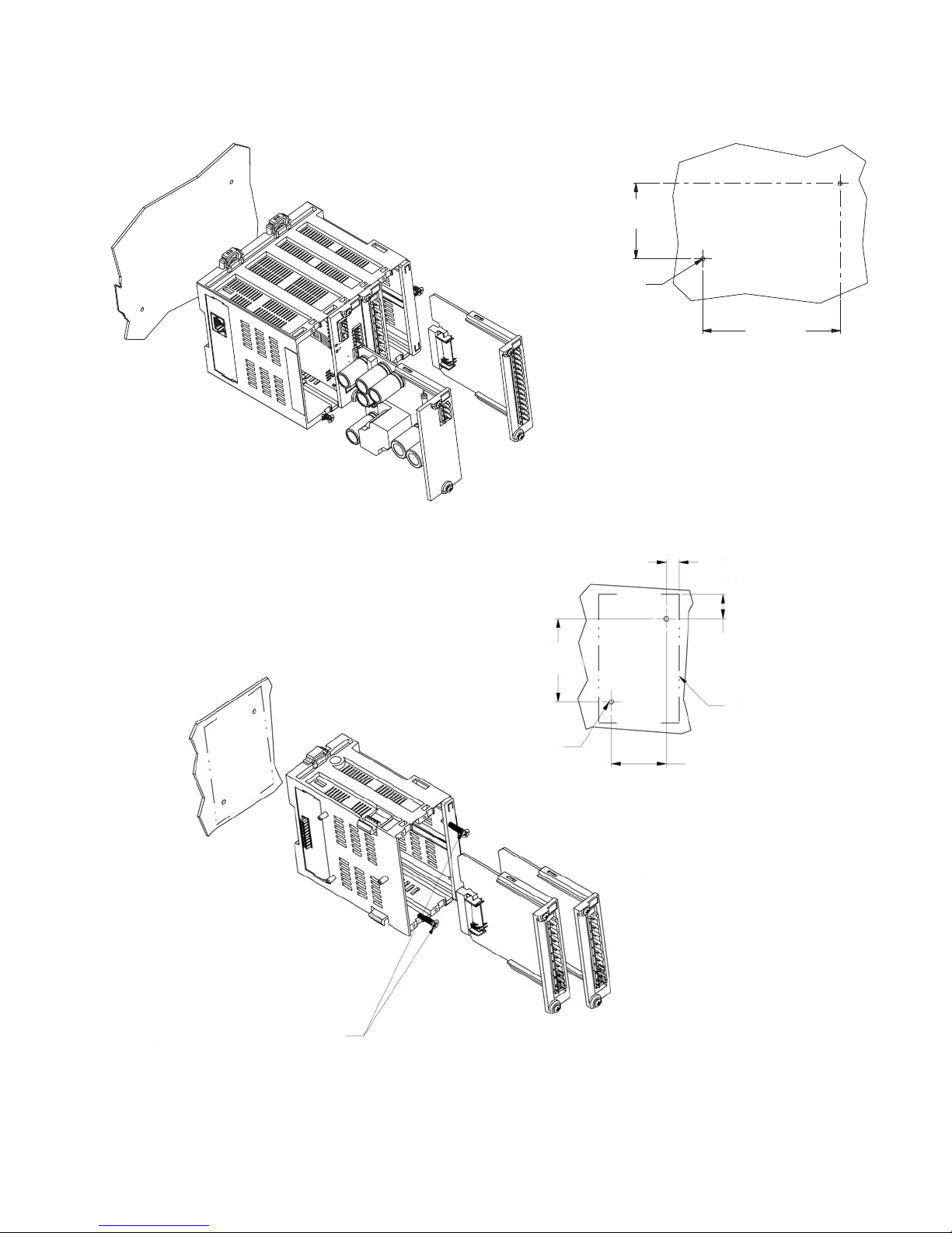
Screw mounts for high vibration environments are illustrated below.
4 MM300 MOTOR MANAGEMENT SYSTEM – QUICKSTART GUIDE
Page 14
CHAPTER 2: INSTALLATION MECHANICAL INSTALLATION
MEETS VIBRATION REQUIREMENT OF
IEC 60255 SEC 21.1, 21.2, & 21.3
2.250”
(57,15 mm)
#6 -32 THREADED HOLE
QTY: 2
4.100”
(104,14 mm)
853727A1.CDR
#6-32X1/2 FT FLAT HEAD PHIL ZINC
QTY: 2; (SUPPLIED); GE PART # 1406-0117
TIGHTENING TORQUE: 10 lb. in.
0.356”
[9.03 mm]
0.672”
[17.06 mm]
1.500”
[38.10 mm]
EXPANSION UNIT
OUTLINE
2.285”
[58.04 mm]
#6-32 THREADED HOLE
QTY: 2
853755A1.cdr
Figure 2-6: Base Unit screw mounting
Figure 2-7: Expansion Unit screw mounting
MM300 MOTOR MANAGEMENT SYSTEM – QUICKSTART GUIDE 5
Page 15

ELECTRICAL INSTALLATION CHAPTER 2: INSTALLATION
Expansion module
allows additional digital
inputs/outputs, RTDs, or
voltage inputs
Expansion module
to base unit with a single connector
•
•
•
I/O card includes:
two
contactor outputs
(form
-A)
six programmable inputs
single-phase VT input (60 to 300 V AC)
Optional three-phase
voltage module
RTDModule
with three RTD inputs
Three-phase and
residual ground CT
inputs
Optional TCP/IP
Ethernet
Core-balance ground CT input
RS485 communications
and thermistor input
Profibus or DeviceNet
Optional fieldbus protocols
Switched power supply
allows AC or DC control
voltage
853740A2.CDR
Electrical installation
This section describes the electrical installation of the MM300 system. An overview of the
MM300 terminal connections is shown below.
CAUTION:
MM300 is not to be used in any way other than described in this manual.
Figure 2-8: MM300 terminal connection overview
CAUTION:
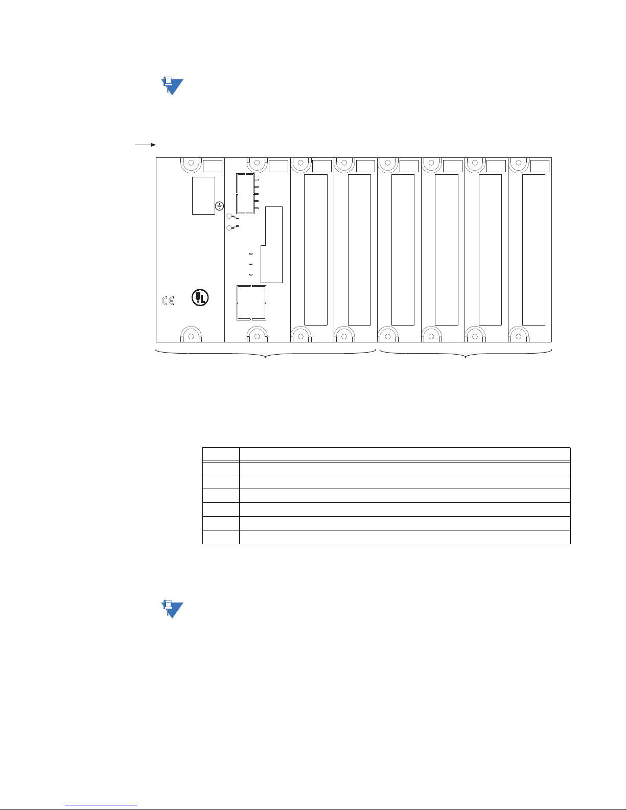
The MM300 can contain up to eight modules. The first four modules (slots A through D)
comprise the base unit, and the next four modules (slots E through H) comprise the
optional expanded unit.
Table 2-1: Module slot position
Slot Module types
Base Unit A Power supply module (High or Low)
B CPU module with communications (1 of 3 Comm Types)
C IO_C or IO_E module
D IO_A module
Expansion Modules E IO_B or IO_C or IO_E or IO_D or IO_G module
F IO_C or IO_E or IO_D or IO_G module
G IO_C or IO_E or IO_D or IO_G module
H IO_C or IO_E or IO_D or IO_G module
The following figure shows a typical module arrangement for an expanded unit .
Use gauge size appropriate for the voltage and current draw of the device.
Table 2-2: Gauge Sizes
CPU Card: Themistor, RS485 and Fieldbus 16 AWG (3.50mm pitch terminals)
PSU / CBCT /IO_C / IO_E / IO_D / IO_G 12 AWG (5.00mm pitch terminals)
IO_A / IO_B 12 AWG (7.62mm pitch terminals)
1. Wire gauge size remains constant; increased pitch distance reflects higher voltage rating.
1
1
6 MM300 MOTOR MANAGEMENT SYSTEM – QUICKSTART GUIDE
Page 16
CHAPTER 2: INSTALLATION ELECTRICAL INSTALLATION
14
13
12
11
10
9
8
7
6
5
4
3
2
1
PSU
60-300 VAC
84-250 VDC
L
gMULTILIN
LISTED
IND.CONT.EQ.
52TL
E200434
Technical Support:
Tel: (905) 294-6222
(North America) 1-800-547-8629
Fax: (905) 201-2098
www.GEMultilin.com
N
MS
NS
THERM RS485
V-
10/100
ETHERNET
GROUND
CT I/P
I
L
C
H
V+
+
–
C
+
–
FIELD BUS
8
7
6
5
4
3
2
1
ABCDEFGH
Slot position
Base unit Expansion modules
853749A1.CDR
14
13
12
11
10
9
8
7
6
5
4
3
2
1
14
13
12
11
10
9
8
7
6
5
4
3
2
1
14
13
12
11
10
9
8
7
6
5
4
3
2
1
8
7
6
5
4
3
2
1
R
SG
NOTE:
It is recommended that you install a circuit disconnection system for control power, near
the device, which should be easily accessible after installation of the unit. This is in case an
emergency power shut-down of the unit is required.
Figure 2-9: Example of module arrangement
Module and terminal identification
The MM300 input/output and protection modules are labeled with the “IO_” prefix followed
by a one-character identifier as follows.
Table 2-3: Input/output module nomenclature
Module Description
IO_A CT module
IO_B VT module
IO_C Two 10 A form-A relays, six 60 to 300 V AC digital inputs, and Aux VT input module.
IO_D Four 10 A form-C relays module.
IO_E Two 10 A form-A relays, six 20 to 60 V DC digital inputs.
IO_G 3 RTD module.
The MM300 terminals are labeled with a three-character identifier. The first character
identifies the module slot position and the second character identifies the terminals within
NOTE:
MM300 MOTOR MANAGEMENT SYSTEM – QUICKSTART GUIDE 7
the module. For example, the first terminal in a module in slot C is identified as “C1”.
Do not confuse the slot designation with the module ordering designation. That is, terminal
“C1” does not imply an IO_C module. Rather, it indicates the first terminal of whatever
module is in slot C.
Page 17
ELECTRICAL INSTALLATION CHAPTER 2: INSTALLATION
A
B
C
M M M
MOTOR
M
Stator Thermistor
M
Field Stop
Field Start
Reset
Core Balance CT
Contactor
MM300
Low Voltage
Motor
Manager
D2
D1
D8
D7
D6
D5
D4
D3
CT Module
PSU
C1
C2
C3
C4
C5
C6
C7
C8
I/O Module- Typ e C
C9
C10
C11
C12
C13
C14
I
C
I
B
I
A
Aux VT
+
-
Com
+
CPU
-
R
I
Surge G d
Core
Balance
Thermistor
RS485
CT2
CT3
G/F
CT1
RS485 Serial Link
Ground at one point
N
L
IN 1 IN 2 IN 3 IN 4 IN 5 IN 6 Com
Relay1 Relay2
LN
GE Multilin
853704A3.cdr
n
Gd
n
G
M
M
Field Stop
Field Start
Reset
MM300
Low Voltage
Motor
Manager
PSU
C1
C2
C3
C4
C5
C6
C7
C8
I/O Module- Type C
C9
C10
C11
C12
C13
C14
Aux VT
N
L
IN 1 IN 2 IN 3 IN 4 IN 5 IN 6 Com
Relay 1 Relay 2
LN
GE Multilin
853704B3.cdr
Low Voltage
DC Supply to
IO Type E
+
-
AC
Control Power
G
Full-voltage non-reversing starter
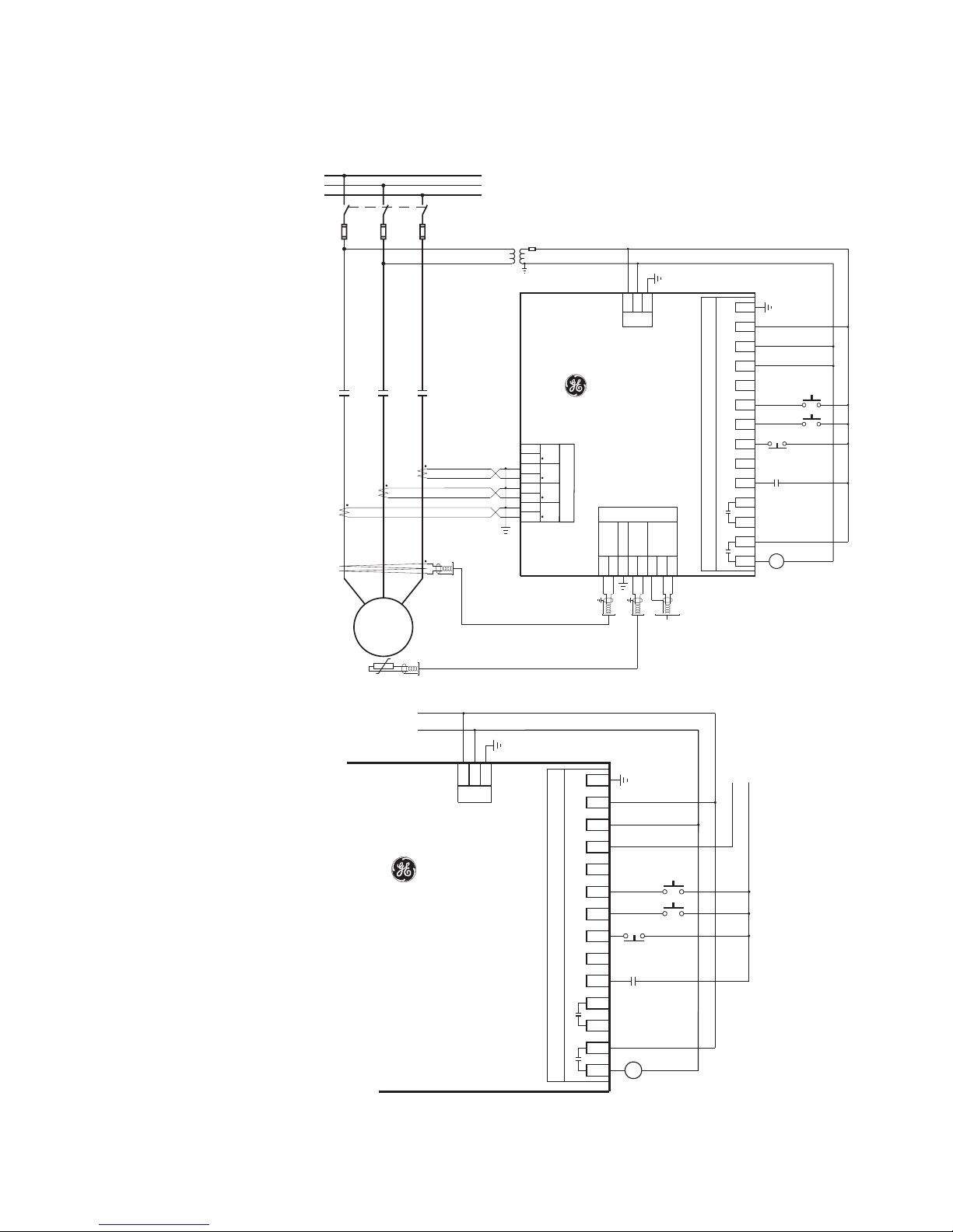
Figure 2-10: Full-voltage non-reversing starter wiring - IO_C
Figure 2-11: Full-voltage non-reversing starter control wiring - IO_E
8 MM300 MOTOR MANAGEMENT SYSTEM – QUICKSTART GUIDE
Page 18
CHAPTER 2: INSTALLATION ELECTRICAL INSTALLATION
NOTE
SCADA, PLC, OR
PERSONAL COMPUTER
COM
OPTOCOUPLER
DATA
MM300 IED
SHIELD
853745A1.CDR
UP TO 32 MM300
OR OTHER IEDs,
MAXIMUM CABLE
LENGTH OF
1200 m (4000 ft.)
LAST
DEVICE
(*) TERMINATING IMPEDANCE AT E ACH END
(typically 120 ohms and 1 nF)
TWISTED PAIR
ZT(*)
RS485 +
RS485 -
COMMON
RS485 +
RS485 -
COMMON
IED
RS485 +
IED
RS485 -
COMMON
GROUND THE SHIELD AT THE
SCADA/PLC/COMPUTER ONLY
OR THE MM300 ONLY
DATA
OPTOCOUPLER
B1
B2
B3
ZT(*)
NOTE:
The above drawing applies only to a high-voltage power supply. If a low-voltage (DC)
power supply is used, an appropriate DC voltage source must be used for this power
supply.
.
The full-voltage non-reversing starter type is a full voltage or across-the-line non-reversing
starter.
When a start control is received, the pre-contactor relay (if any) is picked up for the set precontactor time. When the pre-contactor timer times out, relay1 picks up and seals-in,
picking up contactor M, which starts the motor. When a stop control is received, relay1
drops out, contactor M drops out, and the motor stops. The pre-contactor is omitted on
forced starts (for example, UVR Immediate, External Start).
NOTE:
Connect AUX VT to the Control Supply for correct operation of the UV Restart feature and
correct input readings.
RS485 connections
Figure 2-12: Typical RS485 connection
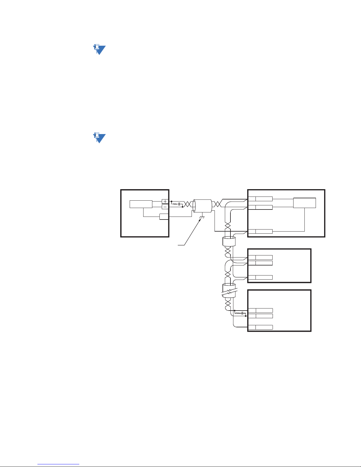
One two-wire RS485 port is provided. Up to 32 MM300 IEDs can be daisy-chained together
on a communication channel without exceeding the driver capability. For larger systems,
additional serial channels must be added. Commercially available repeaters can also be
used to add more than 32 relays on a single channel. Suitable cable should have a
characteristic impedance of 120 ohms and total wire length should not exceed 1200
meters (4000 ft.). Commercially available repeaters will allow for transmission distances
greater than 1200 meters.
Voltage differences between remote ends of the communication link are not uncommon.
For this reason, surge protection devices are internally installed across all RS485 terminals.
Internally, an isolated power supply with an optocoupled data interface is used to prevent
noise coupling.
MM300 MOTOR MANAGEMENT SYSTEM – QUICKSTART GUIDE 9
Page 19

ELECTRICAL INSTALLATION CHAPTER 2: INSTALLATION
Power flow
D1
D2
D4D3
Phase current inputs
D5
D6 D7
CT1 CT2 CT3
D8
G/F
D1
D2
D4D3
Phase current inputs
D5
D6 D7
CT1 CT2 CT3
D8
G/F
D1
D2 D4D3
Phase current inputs
D5
D6 D7
CT1 CT2 CT3
D8
G/F
Two CT Connection
Direct Connection
Residual Ground Connection
Power flowPower flow
Power flowPower flow
853753A1.cdr
CAUTION:
To ensure that all devices in a daisy-chain are at the same potential, it is imperative
that the common terminals of each RS485 port are tied together and grounded only
once, at the master or at the MM300. Failure to do so may result in intermittent or
failed communications.
The source computer/PLC/SCADA system should have similar transient protection devices
installed, either internally or externally. Ground the shield at one point only, as shown in
the figure above, to avoid ground loops.
Correct polarity is also essential. The MM300 IEDs must be wired with all the positive (+)
terminals connected together and all the negative (–) terminals connected together. Each
relay must be daisy-chained to the next one. Avoid star or stub connected configurations.
The last device at each end of the daisy-chain should be terminated with a 120 ohm ¼
watt resistor in series with a 1 nF capacitor across the positive and negative terminals.
Observing these guidelines will ensure a reliable communication system immune to
system transients.
Phase current inputs (IO_A module)
Figure 2-13: Typical phase current input connections
10 MM300 MOTOR MANAGEMENT SYSTEM – QUICKSTART GUIDE
Page 20
CHAPTER 2: INSTALLATION ELECTRICAL INSTALLATION
A
C
B
Power flow
–
+
D1
D2
D4D3
Phase current inputs
MM300
Motor Management System
To switchgear
ground bus
853744A2.CDR
D5
D6 D7
CT1 CT2 CT3
Control power
LN
D8
G/F
Contactor
R
I
CBCT /
50 : 0.025
Core Balance (Zero Sequence)
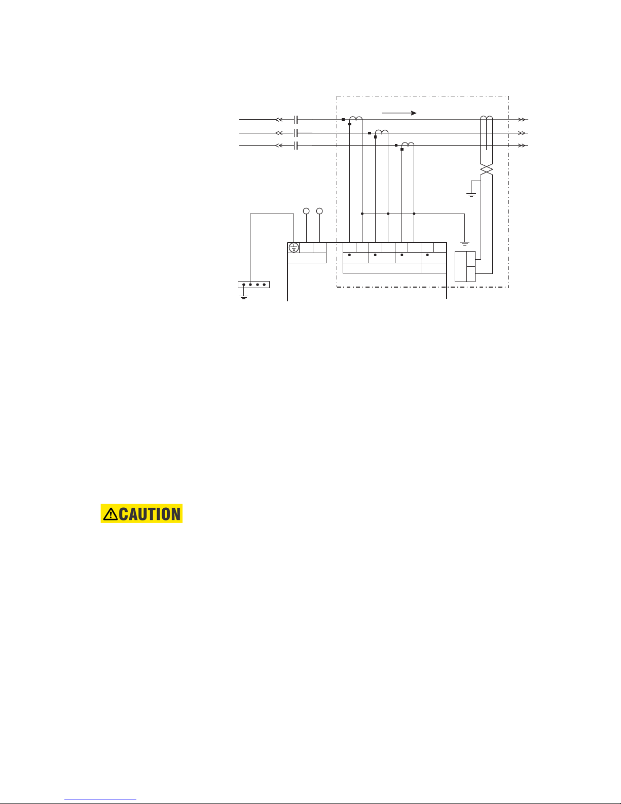
The MM300 has three channels for phase current inputs, each with an isolating
transformer. The phase CTs should be chosen so the FLA is not less than 50% of the rated
phase CT primary. Ideally, the phase CT primary should be chosen such that the FLA is
100% of the phase CT primary or slightly less, never more. This will ensure maximum
accuracy for the current measurements. The maximum phase CT primary current is 1000
A.
The ground CT connection can either be a zero sequence (core balance) installation or a
residual connection. Note that only 1 A and 5 A secondary CTs may be used for the
residual connection. The zero sequence connection is shown in the diagram above, and
this is recommended. Unequal saturation of CTs, CT mismatch, size and location of motor,
resistance of the power system, motor core saturation density, etc. may cause false
readings in the residually connected ground fault circuit. Refer to section 2.2.2.1 for CBCT
connection.
Note that if residual ground connection is selected, the CT primary setpoint used by the
Phase CT's will also be used by the residual ground calculations.
CAUTION:
Polarity of the phase CTs is critical for negative-sequence unbalance calculation,
power measurement, and residual ground current detection (if used).
Two CT configuration Each of the two CTs acts as a current source. The current that comes out of the CT on
phase A flows into the interposing CT on the relay marked CT1. From there, the current
sums with the current that is flowing from the CT on phase C which has just passed
MM300 MOTOR MANAGEMENT SYSTEM – QUICKSTART GUIDE 11
through the interposing CT on the relay marked CT3. This summed current flows through
the interposing CT marked CT2 and from there, the current splits up to return to its
respective source (CT).
Polarity is very important since the value of phase B must be the negative equivalent of
A
Only one ground connection should be made as shown. If two ground connections are
made, a parallel path for current has been created.
In the two CT configuration, the currents will sum vectorially at the common point of the
two CTs. The diagram illustrates the two possible configurations. If one phase is reading
high by a factor of 1.73 on a system that is known to be balanced, simply reverse the
polarity of the leads at one of the two phase CTs (taking care that the CTs are still tied to
ground at some point). Polarity is important.
+ C in order for the sum of all the vectors to equate to zero.
Page 21

ELECTRICAL INSTALLATION CHAPTER 2: INSTALLATION
853715A1.CDR
1.73
11
11
60°
60° 60°
808701A1.CDR
1
C
A
B
1.73
1
B
A
C
Two-phase CT currents
Two-phase CT currents,
180° out-of-phase
NOTE:
Change CT wiring only if the system is de-energized!
Figure 2-14: Two CT connection vector diagram
To illustrate the point further, the following diagram shows how the current in phases A
and C sum up to create phase "B".
Figure 2-15: Two CT connection currents
Once again, if the polarity of one of the phases is out by 180°, the magnitude of the
resulting vector on a balanced system will be out by a factor of 1.73.
On a three-wire supply, this configuration will always work and unbalance will be detected
properly. In the event of a single phase, there will always be a large unbalance present at
the interposing CTs of the relay. If for example phase A was lost, phase A would read zero
while phase B and C would both read the magnitude of phase C. If on the other hand,
phase B was lost, at the supply, phase A would be 180° out-of-phase with phase C and the
vector addition would equal zero at phase B.
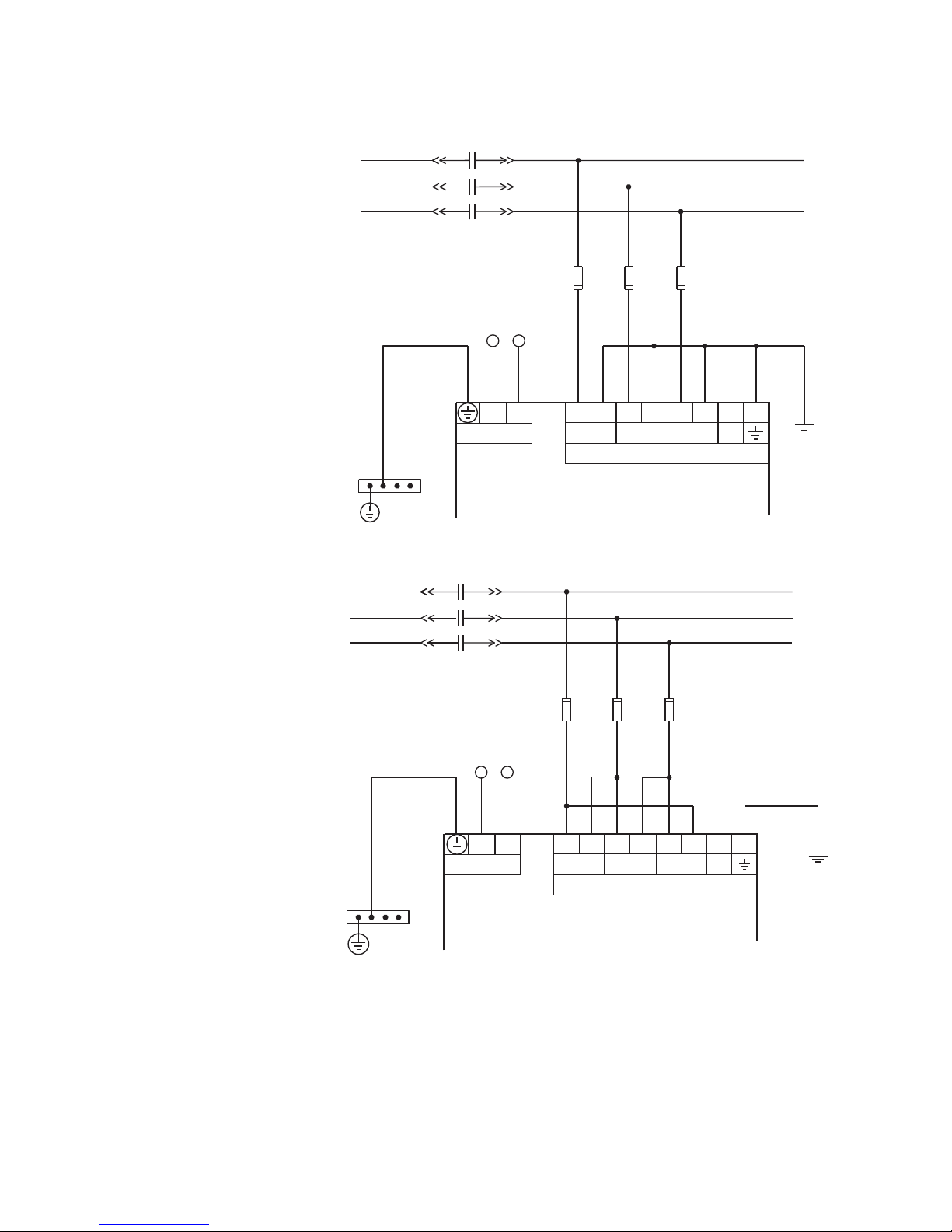
Phase voltage inputs (IO_B module)
The MM300 has three channels for AC voltage inputs. There are no internal fuses or ground
connections on the voltage inputs. Polarity is critical for correct power measurement and
voltage phase reversal operation.
12 MM300 MOTOR MANAGEMENT SYSTEM – QUICKSTART GUIDE
Page 22
CHAPTER 2: INSTALLATION ELECTRICAL INSTALLATION
A
C
B
Contactor
–
+
FUSES - 100 ma typical
E1
E2 E4E3
Phase voltage inputs
MM300
Motor Management System
To switchgear
ground bus
853735A2.CDR
E5
E6 E7
VT1 VT2 VT3
Control power
LN
E8
N/C
A
C
B
Contactor
–
+
FUSES
E1
E2 E4E3
Phase voltage inputs
MM300
Motor Management System
To switchgear
ground bus
853736A2.CDR
E5
E6
VT1 VT2 VT3
Control power
LN
E7 E8
N/C
Figure 2-16: Wye voltage connection
Figure 2-17: Delta voltage connection
MM300 MOTOR MANAGEMENT SYSTEM – QUICKSTART GUIDE 13
Page 23
ELECTRICAL INSTALLATION CHAPTER 2: INSTALLATION
NOTE
NOTE
NOTE
Contactors
~1
~2
~4
~3
853741A3.CDR
~5
~6
MM300
Motor Management System
~8
~9
~11
~10
~12
~13
~7
~14
Two form-A
contact outputs
CONTACT OUTPUT 2
CONTACT INPUT 1 +
Six contact
(digital) inputs
CONTACT OUTPUT 1
CONTACT INPUT 2 +
CONTACT INPUT 3 +
CONTACT INPUT 4 +
CONTACT INPUT 5 +
CONTACT INPUT 6 +
COMMON
VT INPUT
SURGE
L
N
AC
Control power
–
+
B
A
A
B
Type IO_C module connections
Figure 2-18: Typical wiring for type IO_C module
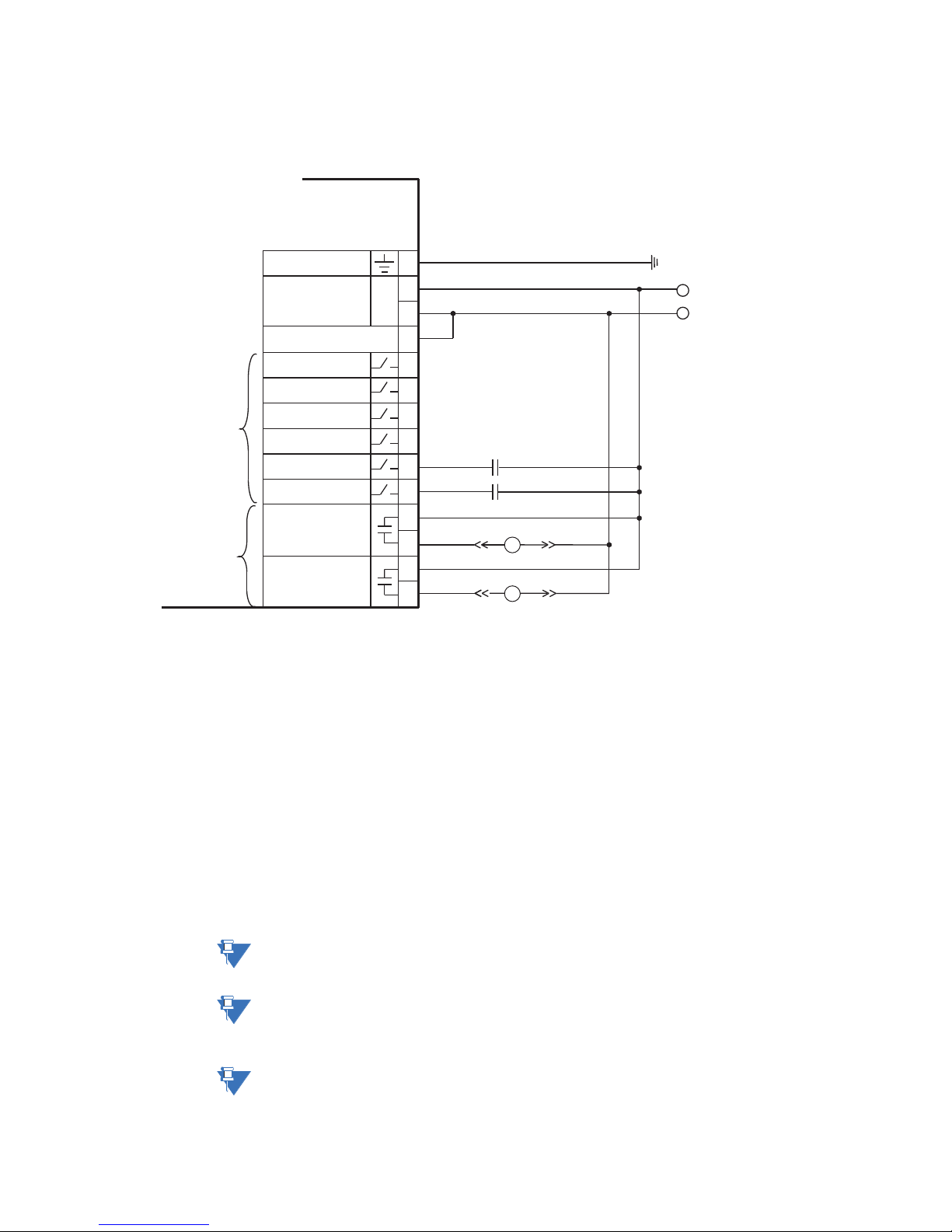
The IO_C module contains two form-A contact output relays, six digital inputs and control
voltage input.
Contact inputs can be programmed to any of the input functions, such as field stop or
process interlock. The exception is that contactor A status is fixed as the first contact input,
and contactor B status (where used) is fixed as the second contact input.
An AC auxiliary supply must be connected to terminals 12 and 13. This auxiliary voltage
(from slot C only) is also used for actual value indication, for auxiliary undervoltage, and for
undervoltage restart. When three-phase voltages are not available, it is also used to
calculate power quantities and is used as a phase angle reference.
When the IO_C module, located in slot C, senses an interruption to its auxiliary supply, it
raises an AC Low Aux Voltage Inhibit, and forces the input state of the contact inputs to
OFF, as the interruption prevents sensing the actual states.
The two contact outputs can be programmed to follow any one of the digital signals
NOTE:
NOTE:
NOTE:
14 MM300 MOTOR MANAGEMENT SYSTEM – QUICKSTART GUIDE
developed by the MM300, such as alarms and status signals. The exception is that the
contactor A relay is fixed as the first contact output, and contactor B relay is fixed as the
second contact output (where used).
Connect AUX VT to the Control Supply for correct operation of the UV Restart feature and
readings of inputs.
All IO_C cards must have the auxiliary input VT wired for proper input sensing. If the
auxiliary voltage on any IO-C module is too low, the contact inputs states for the affected
module will be forced to OFF.
Substitute the slot position of the input/output module (C, E, F, G, H) wherever the tilde
symbol “~” appears in the diagrams above.
Page 24
CHAPTER 2: INSTALLATION ELECTRICAL INSTALLATION
Control
power
~1
~2
~4
~3
853742A1.CDR
~5
~6
MM300
Motor Management System
~8
~9
~11
~10
~12
~13
~7
~14
Four form-C
contact outputs
CONTACT OUTPUT 1
NOT USED
N
CONTACT OUTPUT 2
CONTACT OUTPUT 3
CONTACT OUTPUT 4
NOT USED
–
STOP
TRIP
COIL
+
START
CLOSE
COIL
52a
52b
L
Type IO_D module connections
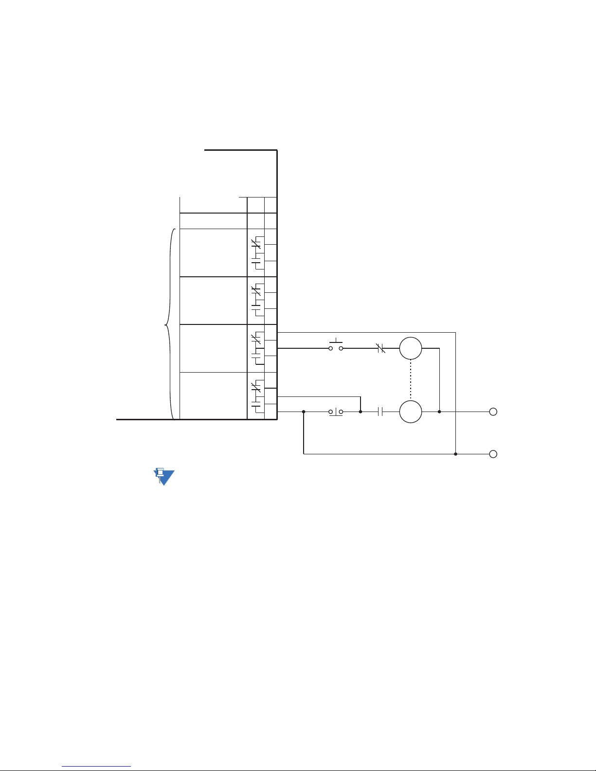
The IO_D module contains four form-C contact output relays.
In general, contact outputs can be programmed to follow any one of the digital signals
developed by the MM300, such as alarms and status signals.
Figure 2-19: Typical wiring for type IO_D contact output module
NOTE:
MM300 MOTOR MANAGEMENT SYSTEM – QUICKSTART GUIDE 15
Substitute the slot position of the input/output module (E, F, G, or H) wherever the tilde
symbol “~” appears in the diagrams above.
Page 25
ELECTRICAL INSTALLATION CHAPTER 2: INSTALLATION
NOTE
Contactors
~1
~2
~4
~3
853754A1.CDR
~5
~6
MM300
Motor Management System
~8
~9
~11
~10
~12
~13
~7
~14
Two form-A
contact outputs
CONTACT OUTPUT 2
CONTACT INPUT 1 +
Six contact
(digital) inputs
CONTACT OUTPUT 1
CONTACT INPUT 2 +
CONTACT INPUT 3 +
CONTACT INPUT 4 +
CONTACT INPUT 5 +
CONTACT INPUT 6 +
COMMON
VT INPUT
SURGE
L
N
AC
Control power
–
+
B
A
A
B
DC supply
–
+
DC supply
Contactor Aux
Type IO_E module connections
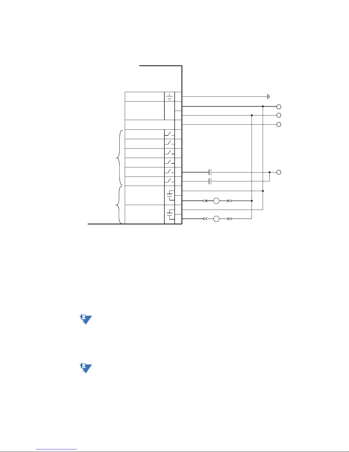
Figure 2-20: Typical wiring for type IO_E module
The IO_E module contains two form-A contact output relays, six digital inputs and a
voltage input, which is a required connection. Contact inputs can be programmed to any
of the input functions, such as field stop or process interlock. The exception is that
contactor A status is fixed as the first contact input, and contactor B status (where used) is
fixed as the second contact input.
An AC auxiliary supply must be connected to terminals 12 and 13 of the IO_E module in
slot C. This auxiliary voltage from slot C is used for actual value indication, for auxiliary
undervoltage, and for undervoltage restart. When three-phase voltages are not available,
it is also used to calculate power quantities and is used as a phase angle reference. When
the IO_E module, located in slot C, senses a low auxiliary voltage inhibit and the
Undervoltage restart function is enabled, the states of the contact inputs are forced to OFF.
NOTE:
NOTE:
RTD sensor connections (IO_G module)
16 MM300 MOTOR MANAGEMENT SYSTEM – QUICKSTART GUIDE
The auxiliary voltage connection is required on all IO_E modules, both in slot C and in
expansion slots.
The two contact outputs can be programmed to follow any one of the digital signals
developed by the MM300, such as alarms and status signals. The exception is that the
contactor A relay is fixed as the first contact output, and contactor B relay is fixed as the
second contact output (where used).
Substitute the slot position of the input/output module (C, E, F, G, H) wherever the tilde
symbol “~” appears in the diagrams above.
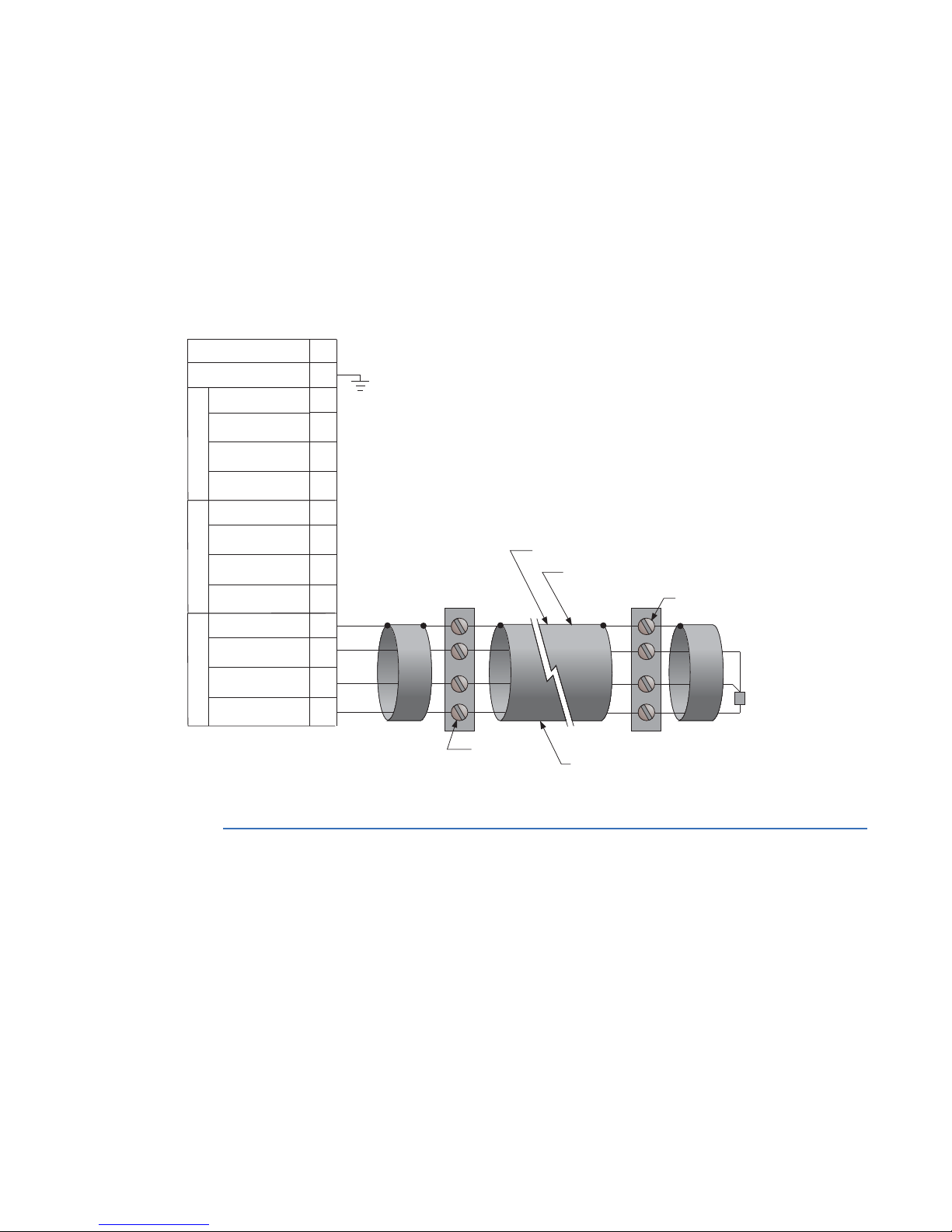
The type IO_G module contains three PT100 RTDs and associated protection functionality.
Page 26
CHAPTER 2: INSTALLATION MAINTENANCE
Motor
starter
Motor
Three-wire shielded cable
RTD
terminals in
motor starter
RTD terminals
at motor
Maximum total lead resistance:
25 ohms for Platinum RTDs
Route cable in separate conduit from
current carrying conductors
RTD in motor
stator or
bearing
853737A3.CDR
MM300 Motor Protection System
Surge ground
~13
~4
~3
~2
~1
Compensation
Return
Hot
Shield
RTD1
~8
~7
~6
~5
Compensation
Return
Hot
Shield
RTD2
~12
~11
~10
~9
Compensation
Return
Hot
Shield
RTD3
N/C
~14
The MM300 monitors up to six RTD inputs for stator, bearing, ambient, or other
temperature monitoring types. The type of each RTD is 100 ohm platinum (DIN 43760).
RTDs must be three-wire type.
The RTD circuitry compensates for lead resistance, provided that each of the three leads is
the same length. Lead resistance should not exceed 25 ohms per lead. Shielded cable
should be used to prevent noise pickup in industrial environments. RTD cables should be
kept close to grounded metal casings and away from areas of high electromagnetic or
radio interference. RTD leads should not be run adjacent to or in the same conduit as high
current carrying wires.
Figure 2-21: RTD wiring
MM300 MOTOR MANAGEMENT SYSTEM – QUICKSTART GUIDE 17
Maintenance
The MM300 requires minimal maintenance. As a microprocessor-based relay, its
characteristics do not change over time. The expected service life of an MM300 is 20 years
when the environment and electrical conditions are within stated specifications.
While the MM300 performs continual self-tests, it is recommended that maintenance be
scheduled with other system maintenance. This maintenance can involve in-service, out-
In-service maintenance
of-service, or unscheduled maintenance.
1. Visual verification of the analog values integrity, such as voltage and current (in
comparison to other devices on the corresponding system).
Page 27

INTERFACING WITH THE MM300 CHAPTER 2: INSTALLATION
2. Visual verification of active alarms, relay display messages, and LED indications.
3. Visual inspection for any damage, corrosion, dust, or loose wires.
4. Event recorder file download with further events analysis.
Out-of-service maintenance
1. Check wiring connections for firmness.
2. Analog values (currents, voltages, RTDs, analog inputs) injection test and metering
accuracy verification. Calibrated test equipment is required.
3. Protection elements setting verification (analog values injection or visual verification
of setting file entries against relay settings schedule).
4. Contact inputs and outputs verification. This test can be conducted by direct change
of state forcing or as part of the system functional testing.
5. Visual inspection for any damage, corrosion, or dust.
6. Event recorder file download with further events analysis.
FASTPATH:
To avoid deterioration of electrolytic capacitors, power up units that are stored in a deenergized state once per year, for one hour continuously.
Unscheduled maintenance (system interruption)
• View the event recorder and oscillography for correct operation of inputs, outputs,
and elements.
Interfacing with the MM300
There are three methods of interfacing with the MM300 Motor Management System.
• Interfacing via the graphical control panel.
• Interfacing via the basic control panel.
• Interfacing via the EnerVista MM300 Setup software.
This section provides an overview of the interfacing methods available with the MM300
using the Graphical and Basic control panels. For additional details on interface
parameters (for example, settings, actual values, etc.), refer to the individual chapters.
MM300 graphical display pages
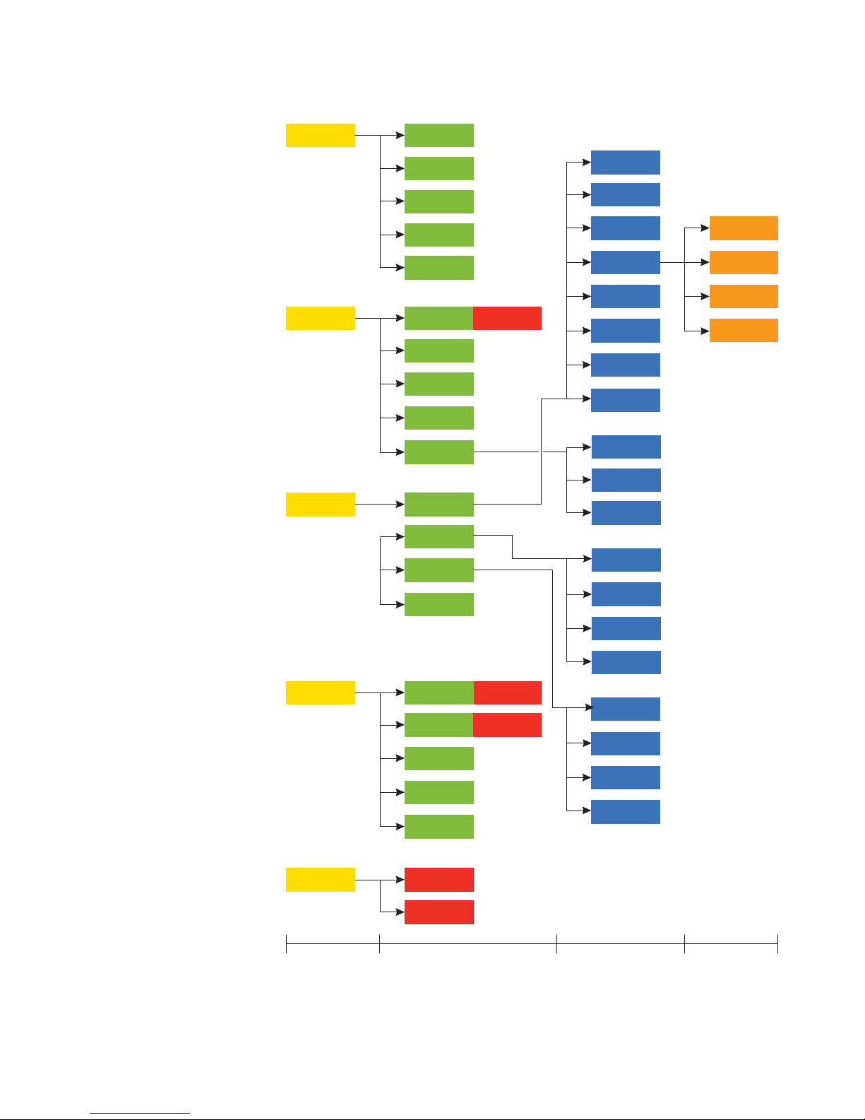
A summary of the MM300 page hierarchy is shown below.
18 MM300 MOTOR MANAGEMENT SYSTEM – QUICKSTART GUIDE
Page 28
CHAPTER 2: INSTALLATION INTERFACING WITH THE MM300
853701A3.CDR
Amps
Power
Volts
Sensor
Values
Inputs
Outputs
System
Message
Flex
Summary
Status
Reset
Protection
Control
Security
Config
Setpoints
CT-VT
Inputs
Outputs
Motor
Comms
System
Events
Counters
Thermal
Mech
Elec
Sensor
Starter
Inhibits
Interlock
UV Restart
Alarms
Trips
Control
Counters
Phasors
Info
Events
Learned
Diag
Clear
Clear
Manual
Auto
Control
Main menu
Level 1 Level 2 Level 3
Summary
V Inputs
V Outputs
Virtual
Figure 2-22: MM300 display page hierarchy
MM300 MOTOR MANAGEMENT SYSTEM – QUICKSTART GUIDE 19
Page 29
INTERFACING WITH THE MM300 CHAPTER 2: INSTALLATION
Introduction to the graphical control panel
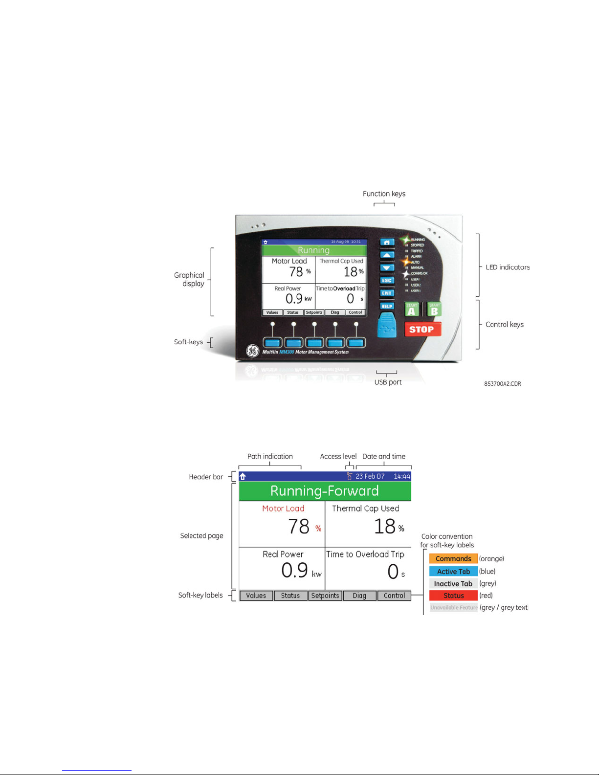
The central feature of the graphical control panel is a 3.5-inch 320 by 240 pixel backlit
color LCD screen. The panel also contains keys (pushbuttons) that control the display and
perform commands. In addition, the interface contains START A, START B, and STOP direct
acting control pushbuttons.
The display also contains several LED indicators that provide a summary of the machine
status. Details are displayed on the screen when the user navigates to the appropriate
page.
Figure 2-23: MM300 front panel with example default display
Graphical display Each display page consists of the three components shown below.
Figure 2-24: Graphical display overview
The header bar (white text on a blue background) displays the hierarchical path name, the
date and time in 24-hour format, and the current password access level. The hierarchical
path is always displayed on the left top side of the graphical display. The present time is
displayed on the right top side. If the test switch is on, the time is replaced with the text
TEST MODE in red.
The soft-key labels are indicated on the bottom line. The soft-keys are used for navigation,
performing functions, and for acknowledgement.
20 MM300 MOTOR MANAGEMENT SYSTEM – QUICKSTART GUIDE
Page 30
CHAPTER 2: INSTALLATION INTERFACING WITH THE MM300
• Navigation: soft-keys can be used to traverse across and down the hierarchy of
pages.
• Functional: soft-keys can be used to perform page-specific functions.
• Acknowledgement: soft keys can be used to acknowledge popup windows.
Soft-keys labels change to show relevant selections for the displayed screen. The color of
each soft-key label indicates its functionality. Soft-keys are highlighted for the displayed
page, unauthorized keys are “greyed-out”, and unused keys are not displayed.
The remainder of the screen shows the selected page. Pages are organized in a
hierarchical or tree-based menu structure. To improve readability, some pages are labeled
with rectangular outlines or colored backgrounds. Some pages contain too many fields to
display at once. These pages display arrows bars at the right edge to indicate that the
page continues below the screen. When recalled, scrolled pages are re-positioned at the
top of the page.
Fields display actual value or setting information, and have behaviours that allow help
display, editing, and control.
Each Actual Value analog field displayed on the home page has an associated alarm limit
and changes color to orange when that limit is exceeded. Fields with an associated trip
limit change their color to red when that limit has tripped. Fields that are disabled or
unavailable are greyed-out.
Keypad The function keys perform the labeled functionality. The summary of function key
operation is shown below.
Table 2-4: Summary of function key operations
Key Operation
HOME Single press recalls the home page; double press recalls the default display
UP Scroll up page, select field, tab to next field, increment value
DOWN Scroll down page, select field, tab to previous field, decrement value
ESC Single press closes pop-up, cancels editing, deselects field, moves to previous page;
ENTER Single press freezes scrolling and selects field, edits selected field, saves edited value;
HELP Displays context sensitive help and Modbus address
sustained press logs out (cancels security passcode entry)
double press sets the selected field/page as default; sustained press logs in (enter
security passcode)
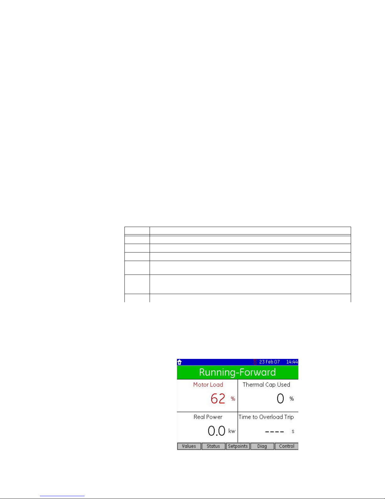
The HOME key always recalls the root or home page. The home page allows access to all
sub-pages and also contains a status and process values summary. Double pressing the
HOME key recalls the default display. Like a screen-saver, the default display appears after
a period of inactivity and displays user-selected information. A typical default display is
shown below, indicating a running motor in the forward direction.
Figure 2-25: Typical default display (actual size)
MM300 MOTOR MANAGEMENT SYSTEM – QUICKSTART GUIDE 21
Page 31
INTERFACING WITH THE MM300 CHAPTER 2: INSTALLATION
The UP and DOWN keys function in different ways depending on their context.
• Where a scroll bar is displayed, the UP and DOWN keys scroll the page up and down.
• Where there is no scroll bar or it is greyed-out, the first press of the UP and DOWN
keys selects the first field. Subsequent presses tab up and down through the fields,
scrolling as required.
• When a field is open for editing, the UP and DOWN keys increment/decrement the
value of that field.
The ENTER key functions in different ways depending on its context.
• If there are no selected fields, the ENTER key will freeze any scroll bars and select the
first field on the display.
• If a field is selected, pressing ENTER will attempt to open it for editing.
• If a field is opened for editing, pressing enter will exit the edit sequence.
• Double pressing the ENTER key at any time selects the displayed page as the default
display.
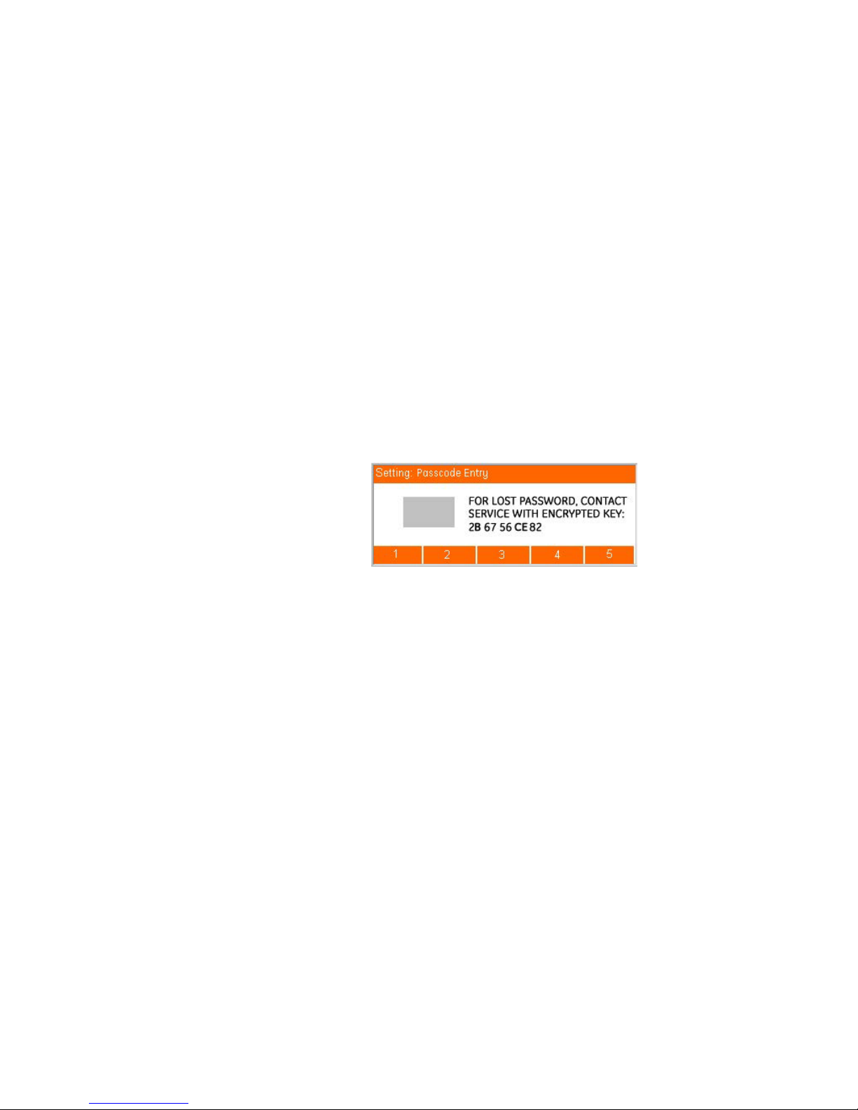
• A sustained press on ENTER prompts the security passcode and displays a dialog box
that allows passcode entry.
For example, pressing and holding the ENTER key, or attempting a control where a
password is required, displays the following page.
Figure 2-26: Passcode entry dialog box
The ESC key functions in different ways depending on its context.
• If a pop-up dialog box is displayed, the ESC key closes it.
• If an edit sequence is in progress, the ESC key cancels the edit.
• If a field is selected, the ESC key de-selects it.
• In all other instances, the ESC key moves back one page in the menu structure.
• A sustained press on the ESC key clears the security passcode and prompts for
confirmation.
The HELP key functions in different ways depending on its context.
• If a field is selected, the HELP key displays a help window for the field.
• If a help window is displayed, the HELP key closes it.
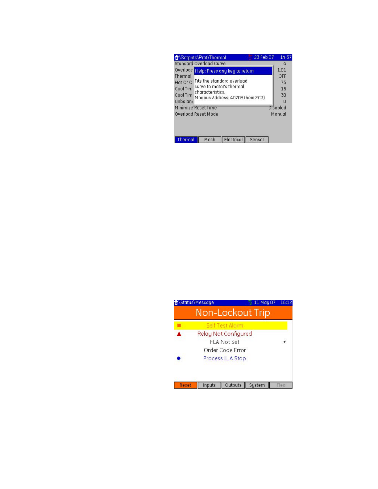
Help windows are also closed when any other key is pressed. A typical help window is
shown below.
22 MM300 MOTOR MANAGEMENT SYSTEM – QUICKSTART GUIDE
Page 32
CHAPTER 2: INSTALLATION INTERFACING WITH THE MM300
Figure 2-27: Typical MM300 help window
Pressing an invalid key displays a message explaining the problem and recommending a
solution. Where the keypress is invalid because a security passcode is required, the dialog
window will be a passcode entry window.
When a lockout occurs that clears when a count-down timer expires or when the thermal
capacity recovers for a restart, the Status > Message page is displayed indicating timer
value or thermal capacity.
Status pages
The status pages provide the user with up-to-date information on the current status of the
MM300.
Status pages are divided into five sections.
• Message (displays all locked out conditions plus conditions such as alarms, internal
faults, control status, etc.).
• Inputs (displays the present state of assigned contact inputs).
• Outputs (displays the present state of assigned contact outputs).
• System (displays the present state of the communications interface).
• Flex (displays the present state of the FlexLogic™ engine and number of lines used.)
A typical display is shown below:
Figure 2-28: Typical status message page
Message types are classified by color and associated icon type, as follows::
• Red Triangle = Trip
• Orange Square = Alarm
• Blue Circle = Inhibit
• Black Text = Information Message
Message can have an associated countdown timer.
MM300 MOTOR MANAGEMENT SYSTEM – QUICKSTART GUIDE 23
Page 33
INTERFACING WITH THE MM300 CHAPTER 2: INSTALLATION
853750A1.CDR
When the relay is first powered up, the status page lists why the relay is not available for
service. This is not an exhaustive list of setpoints to be configured, but is a list of key items
such as FLA, CT Type, starter type and control Source, that must be configured before the
unit will be available for use. Protection values must still be configured for the motor to be
protected correctly.
Inhibits
These include Process Interlock Stop, and Field Stop.
Trips / Alarms
These trigger depending on the protection setpoints. A typical example would be;
“Overload Trip”.
Information Messages
Information pages are split into two groups
– With navigation (shown above, as an Enter symbol on the right side of the
display)
– Without navigation
When a line showing a message (with navigation) is highlighted, pressing Enter will take
the GCP directly to the page in question, so that the situation can be quickly resolved. A
typical example would be “FLA not set”. Selecting this entry on the page will take you to the
\setpoints\config\motor page.
MM300 programming
techniques
CAUTION:
Basic control panel
To streamline the setting entry process, the graphical control panel omits non-functional
settings from the display.
Settings may be changed while the motor is running. However, appropriate measures
must be taken to limit the consequences of entering unintended or misunderstood
setting values. Consequences of inappropriate settings to the specific application at
hand include loss of protection, loss of control, and undesired starting or stopping.
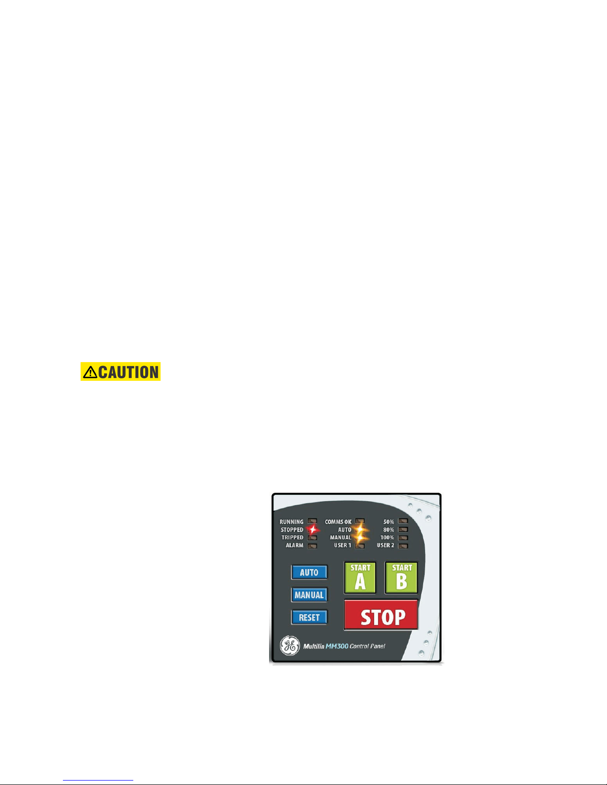
The MM300 basic control panel provides the basic start and stop panel functionality, as
well as a series of LED indications. The basic control panel is illustrated below.
Figure 2-29: Basic control panel
The following LEDs are provided:
• Two USER LEDs (USER 1 and USER 2). the user can select parameters from a list
24 MM300 MOTOR MANAGEMENT SYSTEM – QUICKSTART GUIDE
Page 34

CHAPTER 2: INSTALLATION ENERVISTA MM300 SETUP SOFTWARE
• 50%/80%/100% - showing motor load
• RUNNING, STOPPED, TRIPPED, and ALARM
• COMMS OK
•AUTO and MANUAL
EnerVista MM300 Setup Software
Although settings can be entered manually using the control panel keys, a PC can be used
to download values through the communications port. The EnerVista MM300 Setup
software is available from GE Multilin to make this as convenient as possible. With
EnerVista MM300 Setup running, it is possible to:
• Program and modify settings
• Load and save setting files to and from a disk
• Read actual values
• Monitor status
• Read pre-trip data and event records
• Get help on any topic
• Upgrade the MM300 firmware
The EnerVista MM300 Setup software allows immediate access to all MM300 features with
easy to use pull down menus in the familiar Windows environment. This section provides
the necessary information to install EnerVista MM300 Setup, upgrade the relay firmware,
and write and edit setting files.
The EnerVista MM300 Setup software can run without a MM300 connected to the
computer. In this case, settings may be saved to a file for future use. If an MM300 is
connected to a PC and communications are enabled, the MM300 can be programmed
from the setting screens. In addition, measured values, status and trip messages can be
displayed with the actual value screens.
Software requirements
The following requirements must be met for the EnerVista MM300 Setup software.
• Windows 7 or Windows 8.1 is installed and running properly.
The EnerVista MM300 Setup software can be installed from either the GE EnerVista CD or
the GE Multilin website at
www.gegridsolutions.com/Multilin.
Troubleshooting the USB driver
When the Setup Software is installed on the Windows 2000 or XP operating system, and
the device is power recycled while the native USB port is still connected to the PC, the USB
driver in the PC Program may get lost and the setup software may fail to recognize the
USB device. If this happens, the ‘MM300 USB Serial Emulation (COM #)’ will be missing in the
Setup Software’s Device Setup window. To overcome the problem:
1. Remove the USB cable from the native port of the device.
2. Wait for 20 Seconds and connect the cable back to the native port of the device.
MM300 MOTOR MANAGEMENT SYSTEM – QUICKSTART GUIDE 25
Page 35
ENERVISTA MM300 SETUP SOFTWARE CHAPTER 2: INSTALLATION
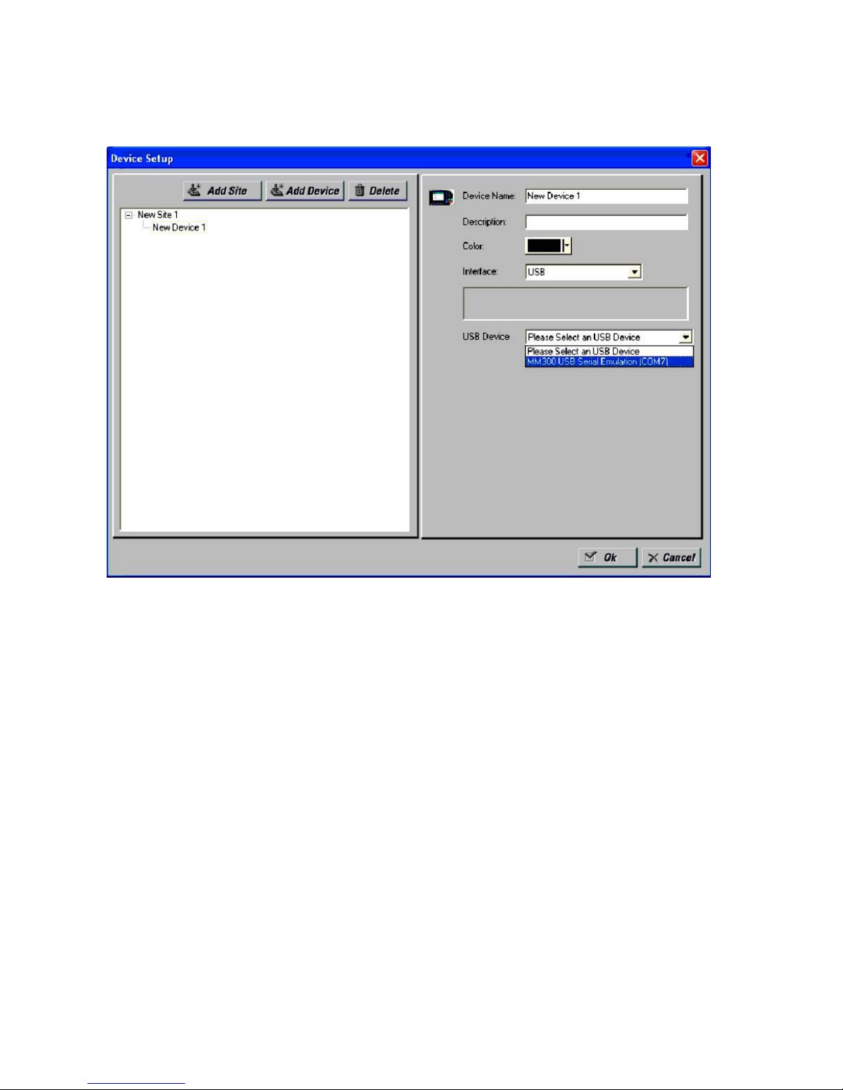
3. Check the Setup Software for the availability of the USB Device on the Device setup
Window. It will automatically reappear on the ‘USB Device’ list as ‘MM300 USB Serial
Emulation (COM #)’ as shown in the image below.
4. If the USB Device is not recognized automatically in the Setup Software, repeat the
same procedure 2 or 3 times until the PC Program recognizes the USB device (and
‘MM300 USB Serial Emulation (COM #)’ reappears in dropdown of ‘USB Device’ list).
26 MM300 MOTOR MANAGEMENT SYSTEM – QUICKSTART GUIDE
Page 36
CHAPTER 2: INSTALLATION ENERVISTA MM300 SETUP SOFTWARE
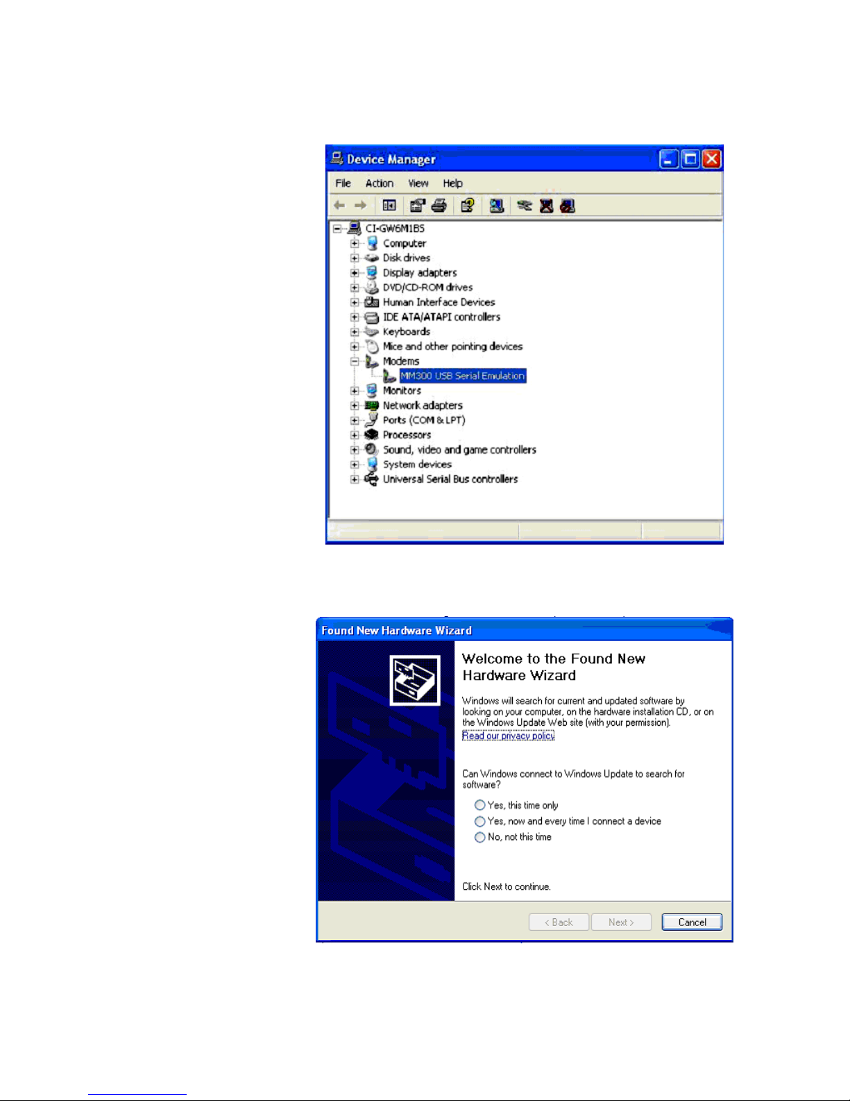
5. If problem still persists, uninstall the USB driver from Computer’s ‘Device Manager’
under tree-branch modems from the Installation folder. To uninstall it, right click on
MM300 USB Serial Emulation and select Uninstall.
6. After the uninstall, remove the USB cable from the Device’s native USB port, wait for at
least 10 Seconds and reconnect it.
7. Now the ‘Found New Hardware Wizard’ will open, select No, not this time and press
the Next button.
MM300 MOTOR MANAGEMENT SYSTEM – QUICKSTART GUIDE 27
Page 37
ENERVISTA MM300 SETUP SOFTWARE CHAPTER 2: INSTALLATION
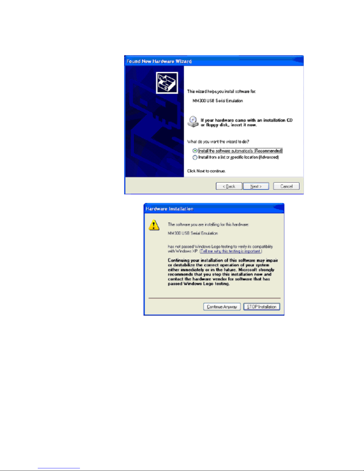
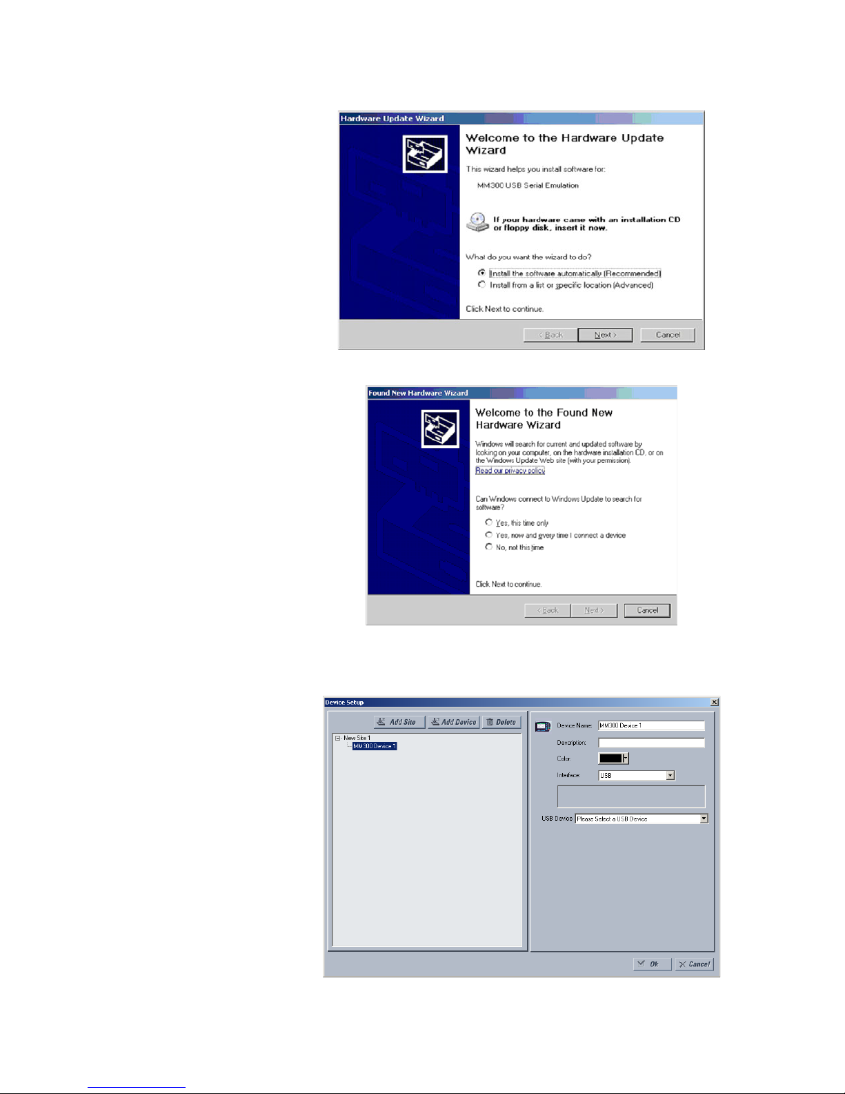
8. Select Install the software automatically (Recommended) and press the Next
button.
9. Press Continue Anyway.
10. At the end press Finish.
11. Check in the Setup Software for the availability of the USB Device on the Device setup
Window. Now the device will reappear on the ‘USB Device’ list.
For the current version, the USB driver can not be installed on Windows Vista Operating
System and communication to the Device via the Native USB port is not supported.
Installing the EnerVista MM300 Setup software
After ensuring the minimum requirements indicated earlier, use the following procedure to
install the EnerVista MM300 Setup software from the enclosed GE EnerVista CD.
1. Insert the GE EnerVista CD into your CD-ROM drive.
2. Click the Install Now button and follow the installation instructions to install the nocharge EnerVista software on the local PC.
3. When installation is complete, start the EnerVista Launchpad application.
28 MM300 MOTOR MANAGEMENT SYSTEM – QUICKSTART GUIDE
Page 38
CHAPTER 2: INSTALLATION ENERVISTA MM300 SETUP SOFTWARE
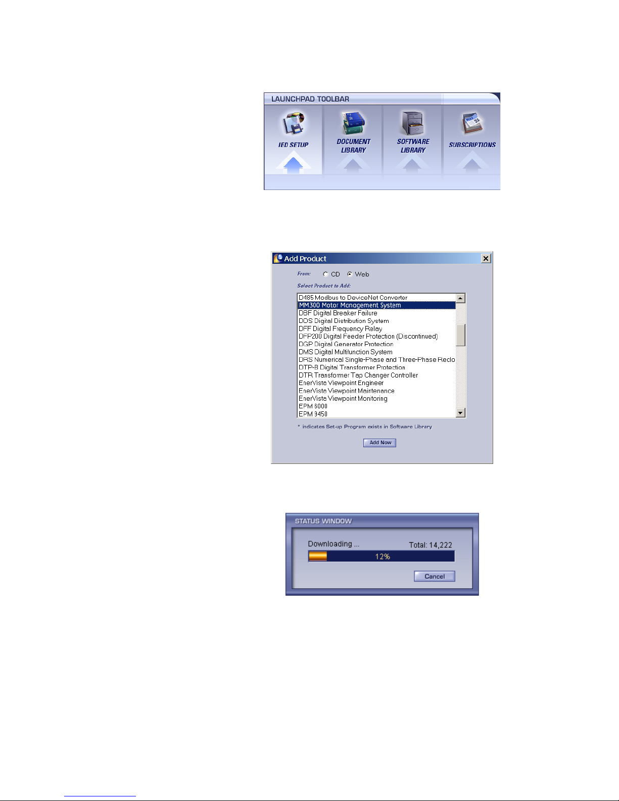
4. Click the IED Setup section of the Launch Pad toolbar.
5. In the EnerVista Launchpad window, click the Add Product button and select the
MM300 Motor Management System as shown below. Select the Web option to ensure
the most recent software release, or select CD if you do not have a web connection,
then click the Add Now button to list software items for the MM300.
6. EnerVista Launchpad will obtain the latest installation software from the Web or CD
and automatically start the installation process. A status window with a progress bar
will be shown during the downloading process.
7. Select the complete path, including the new directory name, where the EnerVista
MM300 Setup software will be installed.
8. Click on Next to begin the installation. The files will be installed in the directory
indicated, the USB driver will be loaded into the computer, and the installation
program will automatically create icons and add EnerVista MM300 Setup software to
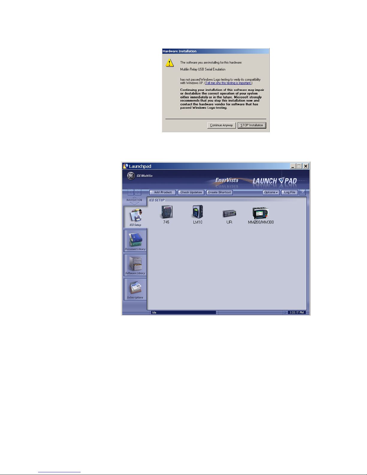
the Windows start menu. The following screen will appear:
MM300 MOTOR MANAGEMENT SYSTEM – QUICKSTART GUIDE 29
Page 39
ENERVISTA MM300 SETUP SOFTWARE CHAPTER 2: INSTALLATION
9. Press the Continue Anyway button, then click Finish to end the installation. The
MM300 device will be added to the list of installed IEDs in the EnerVista Launchpad
window, as shown below.
If you are going to communicate from your computer to the MM300 Relay using the
USB port:
10. Plug the USB cable into the USB port on the MM300 Relay then into the USB port on
your computer. The following screen will appear:
30 MM300 MOTOR MANAGEMENT SYSTEM – QUICKSTART GUIDE
Page 40
CHAPTER 2: INSTALLATION ENERVISTA MM300 SETUP SOFTWARE
11. Select Install... Automatically
12. Select No, not this time. The above Hardware Installation warning screen (see #8
above) will reappear. Press the Continue Anyway button.
13. In EnerVista > Device Setup:
MM300 MOTOR MANAGEMENT SYSTEM – QUICKSTART GUIDE 31
Page 41

CONNECTING ENERVISTA MM300 SETUP TO THE RELAY CHAPTER 2: INSTALLATION
Select USB as the Interface type.
14. Select the appropriate USB device.
Upgrading the software
The latest EnerVista software and firmware can be downloaded from:
https://www.gegridsolutions.com/app/ViewFiles.aspx?prod=mm300&type=7
After upgrading, check the version number under Help > About. If the new version does
not display, try uninstalling the software and reinstalling the new versions.
Connecting EnerVista MM300 Setup to the relay
Configuring serial communications
Before starting, verify that the cable is properly connected to either the USB port on the
front panel of the device (for USB communications) or to the Serial port on the rear of the
device. This example demonstrates a Serial connection.
1. Install and start the latest version of the EnerVista MM300/MM200 Setup software
(available from the GE Multilin web site). See the previous section for the installation
procedure.
2. Click on the Device Setup button to open the Device Setup window and click the Add
Site button to define a new site.
3. Enter the desired site name in the "Site Name" field. If desired, a short description of
the site can also be entered. In this example, we will use “New Site 1” as the site name.
4. The new site will appear in the upper-left list in the EnerVista MM300/MM200
Setup window.
5. Click the Add Device button to define the new device.
6. Enter the desired name in the "Device Name" field and a description (optional) of the
device.
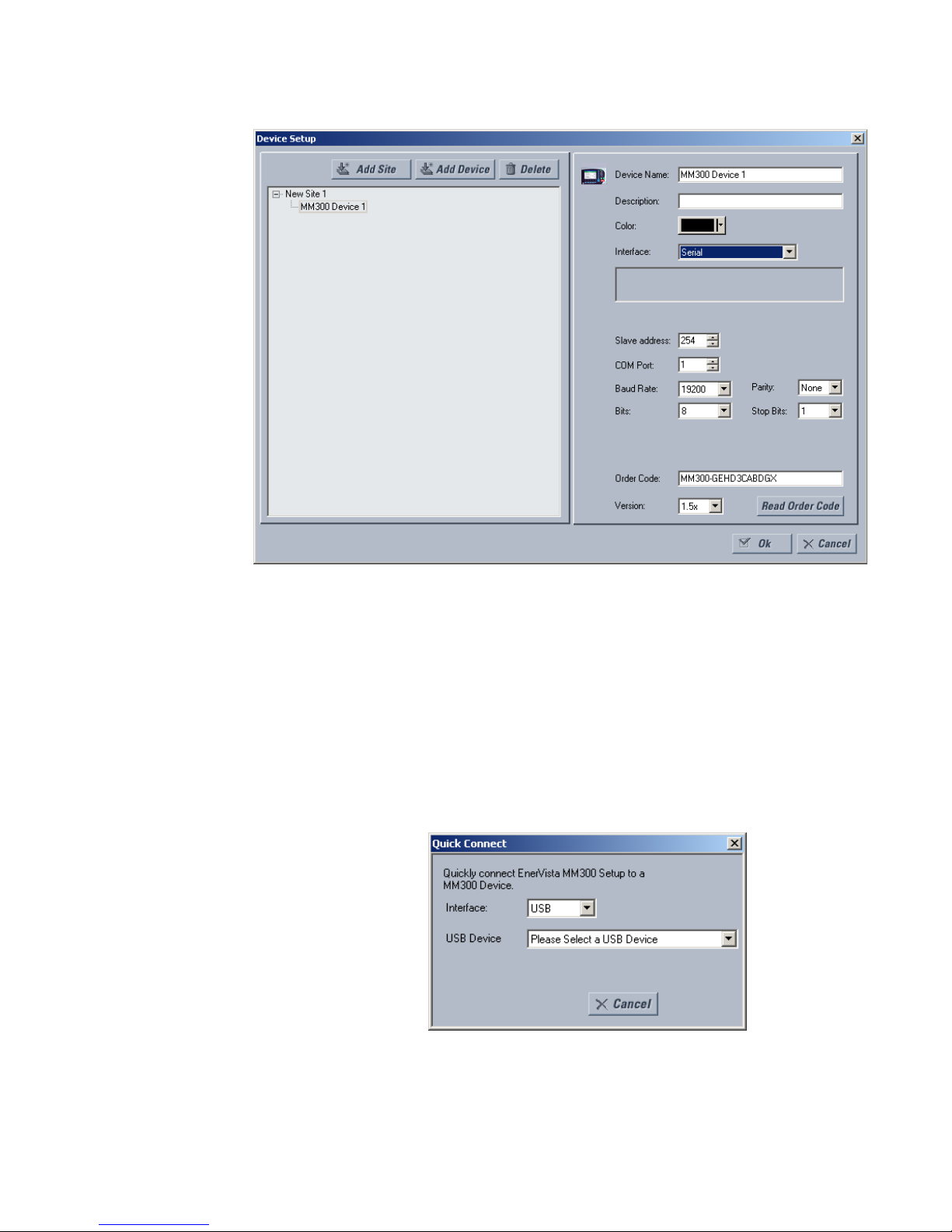
7. Select “Serial Device” from the Interface drop-down list.
32 MM300 MOTOR MANAGEMENT SYSTEM – QUICKSTART GUIDE
Page 42
CHAPTER 2: INSTALLATION CONNECTING ENERVISTA MM300 SETUP TO THE RELAY
8. Click the Read Order Code button to connect to the MM300 device and upload the
order code.
9. Click OK when the relay order code has been received. The new device will be added
to the Site List window (or Online window) located in the top left corner of the main
EnerVista MM300/MM200 Setup window.
The MM300 Site Device has now been configured for Serial communications. Proceed to
Connecting to the Relay below, to begin communications.
Using the Quick Connect feature
The Quick Connect button can be used to establish a fast connection through the front
panel USB port of a MM300
QuickConnect button is pressed:
relay. The following window will appear when the
As indicated by the window, the "Quick Connect" feature can quickly connect the EnerVista
MM300/MM200 Setup
drop-down list. Select "MM300 Relay" and press the Connect button.
When connected, a new Site called “Quick Connect” will appear in the Site List window.
MM300 MOTOR MANAGEMENT SYSTEM – QUICKSTART GUIDE 33
software to a MM300 front port if the USB is selected in the interface
Page 43
CONNECTING ENERVISTA MM300 SETUP TO THE RELAY CHAPTER 2: INSTALLATION
The MM300 Site Device has now been configured via the Quick Connect feature for either
USB or Serial communications. Proceed to Connecting to the Relay below, to begin
communications.
Connecting to the relay
Now that the communications parameters have been properly configured, the user can
easily communicate with the relay.
1. Expand the Site list by double clicking on the site name or clicking on the «+» box to
list the available devices for the given site.
2. Desired device trees can be expanded by clicking the «+» box. The following list of
headers is shown for each device:
Device Definition
Setpoints
Values
Diagnostics
Device Summary
Status
Exerciser
Maintenance.
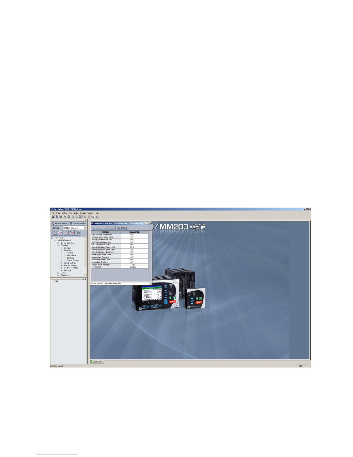
3. Expand any list item and double click on any item contained in the expanded list to
open that item, as shown below:
4. The window related to that item will open with a corresponding status indicator tab on
the lower left of the EnerVista SR3 Setup window.
5. If the status indicator is red, verify that the seria or USB cable is properly connected to
the relay, and that the relay has been properly configured for communications (steps
described earlier).
34 MM300 MOTOR MANAGEMENT SYSTEM – QUICKSTART GUIDE
Page 44
CHAPTER 2: INSTALLATION WORKING WITH SETPOINTS AND SETPOINT FILES
The "item" settings can now be edited, printed, or changed. Other windows can be
displayed and edited in a similar manner. These windows can be arranged, and resized at
will.
Working with setpoints and setpoint files
Engaging a device
The EnerVista MM300/MM200 Setup software may be used in on-line mode (relay
connected) to directly communicate with a relay. Communicating relays are organized
and grouped by communication interfaces and into sites. Sites may contain any number
of relays selected from the product series.
Entering setpoints
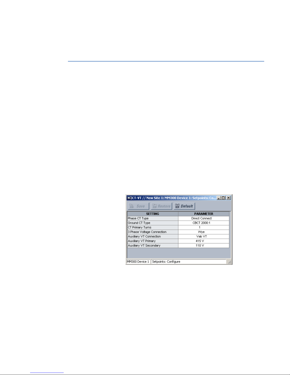
The System Setup page will be used as an example to illustrate the entering of setpoints. In
this example, we will be changing the current sensing setpoints.
1. Establish communications with the relay.
2. Select the Setpoint > Configure > CT-VT menu item.
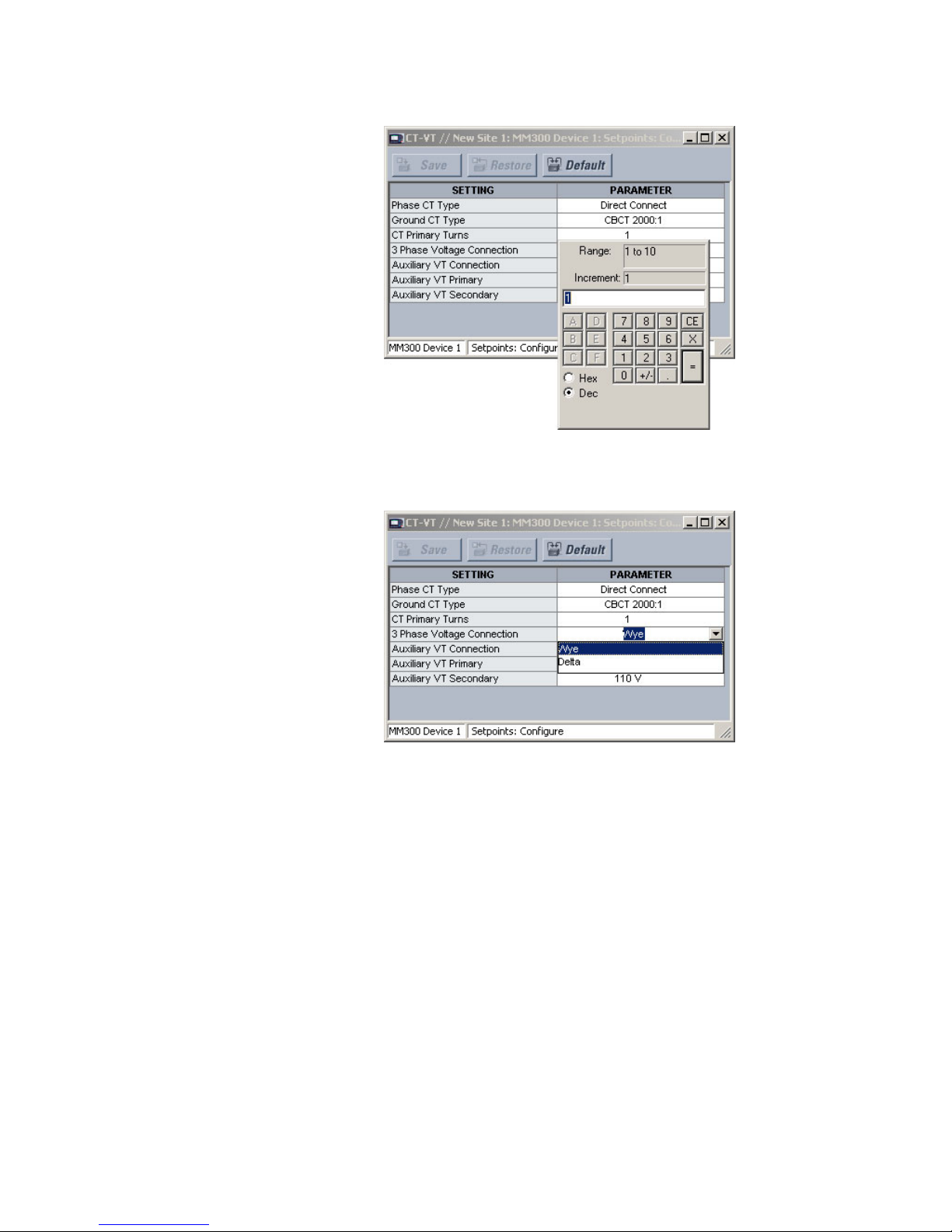
3. Select the CT Primary setpoint by clicking anywhere in the parameter box. This will
display three arrows: two to increment/decrement the value and another to launch
the numerical keypad.
4. Clicking the arrow at the end of the box displays a numerical keypad interface that
MM300 MOTOR MANAGEMENT SYSTEM – QUICKSTART GUIDE 35
allows the user to enter a value within the setpoint range displayed near the top of the
keypad: Click = to exit from the keypad and keep the new value. Click on X to exit from
the keypad and retain the old value.
Page 45
WORKING WITH SETPOINTS AND SETPOINT FILES CHAPTER 2: INSTALLATION
5. For setpoints requiring non-numerical pre-set values (e.g. CT Primary below), clicking
anywhere within the setpoint value box displays a drop-down selection menu arrow.
Select the desired value from this list.
6. For setpoints requiring an alphanumeric text string (e.g. "relay name"), the value may
be entered directly within the setpoint value box.
7. In the Setpoint > Config > CT-VT dialog box, click on Save to save the values into the
MM300 . Click YES to accept any changes and exit the window. Click Restore to retain
previous values. Click Default to restore Default values.
File support
Opening any EnerVista MM300/MM200 Setup file will automatically launch the application
or provide focus to the already opened application. If the file is a Settings file (has a ‘SR3’
extension) which had been removed from the Settings List tree menu, it will be added back
to the Settings List tree.
New files will be automatically added to the tree.
Using setpoints files
The EnerVista MM300/MM200 Setup software interface supports three ways of handling
changes to relay settings:
36 MM300 MOTOR MANAGEMENT SYSTEM – QUICKSTART GUIDE
Page 46

CHAPTER 2: INSTALLATION WORKING WITH SETPOINTS AND SETPOINT FILES
• In off-line mode (relay disconnected) to create or edit relay settings files for later
download to communicating relays.
• Directly modifying relay settings while connected to a communicating relay, then
saving the settings when complete.
• Creating/editing settings files while connected to a communicating relay, then saving
them to the relay when complete.
Settings files are organized on the basis of file names assigned by the user. A Settings file
contains data pertaining to the following types of relay settings:
•Configure
•Protection
• Control
• Security Settings
• Modbus User Map
•FlexLogic
Factory default values are supplied and can be restored after any changes.
The EnerVista MM300/MM200 Setup EnerVista MM300/MM200 Setup displays relay
setpoints with the same hierarchy as the front panel display.
Downloading and saving setpoints files
Setpoints must be saved to a file on the local PC before performing any firmware
upgrades. Saving Setpoints is also highly recommended before making any Setpoint
changes or creating new Setpoint files.
The Setpoint files in the EnerVista MM300/MM200 Setup window are accessed in the Files
Window. Use the following procedure to download and save Setpoint files to a local PC.
1. Ensure that the site and corresponding device(s) have been properly defined and
configured as shown in Connecting EnerVista MM300/MM200 Setup to the Relay,
above.
2. Select the desired device from the site list.
3. Select the Online > Read Device Settings from Device menu item (at the top of the
page), or right-click on the device and select Read Device Settings to obtain settings
information from the device.
4. After a few seconds of data retrieval, the software will request the name and
destination path of the setpoint file. The corresponding f ile extension will be
automatically assigned. Press Receive to complete the process. A new entry will be
added to the tree, in the File pane, showing path and file name for the setpoint file.
Adding setpoints files to the environment
The EnerVista MM300/MM200 Setup software provides the capability to review and
manage a large group of setpoint files. Use the following procedure to add an existing file
to the list.
MM300 MOTOR MANAGEMENT SYSTEM – QUICKSTART GUIDE 37
Page 47

WORKING WITH SETPOINTS AND SETPOINT FILES CHAPTER 2: INSTALLATION
1. In the files pane, right-click on Files and select the Add Existing Setting File item as
shown:
CAUTION:
2. The Open dialog box will appear, prompting the user to select a previously saved
setpoint file. As for any other MS Windows® application, browse for the file to be
added then click Open. The new file and complete path will be added to the file list.
Loading setpoints from a file
An error message will occur when attempting to download a setpoint file with a
revision number that does not match the relay firmware. If the firmware has been
upgraded since saving the setpoint file, see Upgrading Setpoint Files to a New Revision,
above, for instructions on changing the revision number of a setpoint file.
The following procedure illustrates how to load setpoints from a file. Before loading a
setpoints file, it must first be added to the EnerVista MM300/MM200 Setup
described in the section, Adding Setpoints Files to the Environment.
1. Select the previously saved setpoints file from the File pane of the software main
window.
2. Select the Offline > Edit Settings File Properties menu item and verify that the
corresponding file is fully compatible with the hardware and firmware version of the
target relay. If the versions are not identical, see Upgrading Setpoint Files to a New
Revision, above, for details on changing the setpoints file version.
3. Right-click on the selected file and select the Write Settings File to Device item.
4. Select the target relay from the list of devices shown and click Send. If there is an
incompatibility, an "Incompatible Device" error message will occur:
environment as
38 MM300 MOTOR MANAGEMENT SYSTEM – QUICKSTART GUIDE
Page 48

CHAPTER 2: INSTALLATION UPGRADING RELAY FIRMWARE
NOTE
If there are no incompatibilities between the target device and the settings file, the data
will be transferred to the relay. An indication of the percentage completed will be shown at
the bottom of the main window.
Uninstalling files and clearing data
The unit can be decommissioned by turning off the power to the unit and disconnecting
the wires to it. Files can be cleared after uninstalling the EnerVista software or MM300
device, for example to comply with data security regulations.On the computer, settings
files can be identified by the .m30 extension.
To clear the current settings file do the following:
1. Create a default settings file.
2. Write the default settings file to the relay.
3. Delete all other files with the .m30 extension.
4. Delete any other data files , which can be in standard formats, such as COMTRADE or
.csv.
You cannot directly erase the flash memory, but all records and settings in that memory
can be deleted. Do this using these commands:
DIAGNOSTICS > COMMANDS
• CLEAR LAST TRIP DATA PROMPT
• CLEAR TRIP COUNTERS
• CLEAR MAINTENANCE TIMER
• RESET MOTOR INFORMATION
Upgrading relay firmware
To upgrade the MM300 firmware, follow the procedures listed in this section. Upon
successful completion of this procedure, the MM300
installed with the factory default setpoints.The latest firmware files are available from the
GE Multilin website at
NOTE:
EnerVista MM300/MM200 Setup EnerVista MM300/MM200 Setup software prevents
http:// www.GEmultilin.com.
incompatible firmware from being loaded into a MM300 relay.
NOTE:
Before upgrading firmware, it is very important to save the current settings to a file on
your PC. After the firmware has been upgraded, it will be necessary to load this file back
into the MM300 MM300 . Refer to Downloading and Saving Setpoints Files for details on
saving relay setpoints to a file.
NOTE:
All IO_C cards must be connected to aux. voltage during any firmware upgrade procedure.
If aux. voltage is not connected, calibration data from IO_C cards will not be restored
during the upgrade procedure.
Loading new relay firmware
Loading new firmware into the MM300 flash memory is accomplished as follows:
1. Connect the RJ45 port on the relay (labelled "RS485 to Control Panel") to the RS232
port (COM1) on the local PC, using an RS232 (female)-to-RJ45 (male) custom cable (p/n
0804-0180).
MM300 will have new firmware
MM300 MOTOR MANAGEMENT SYSTEM – QUICKSTART GUIDE 39
Page 49
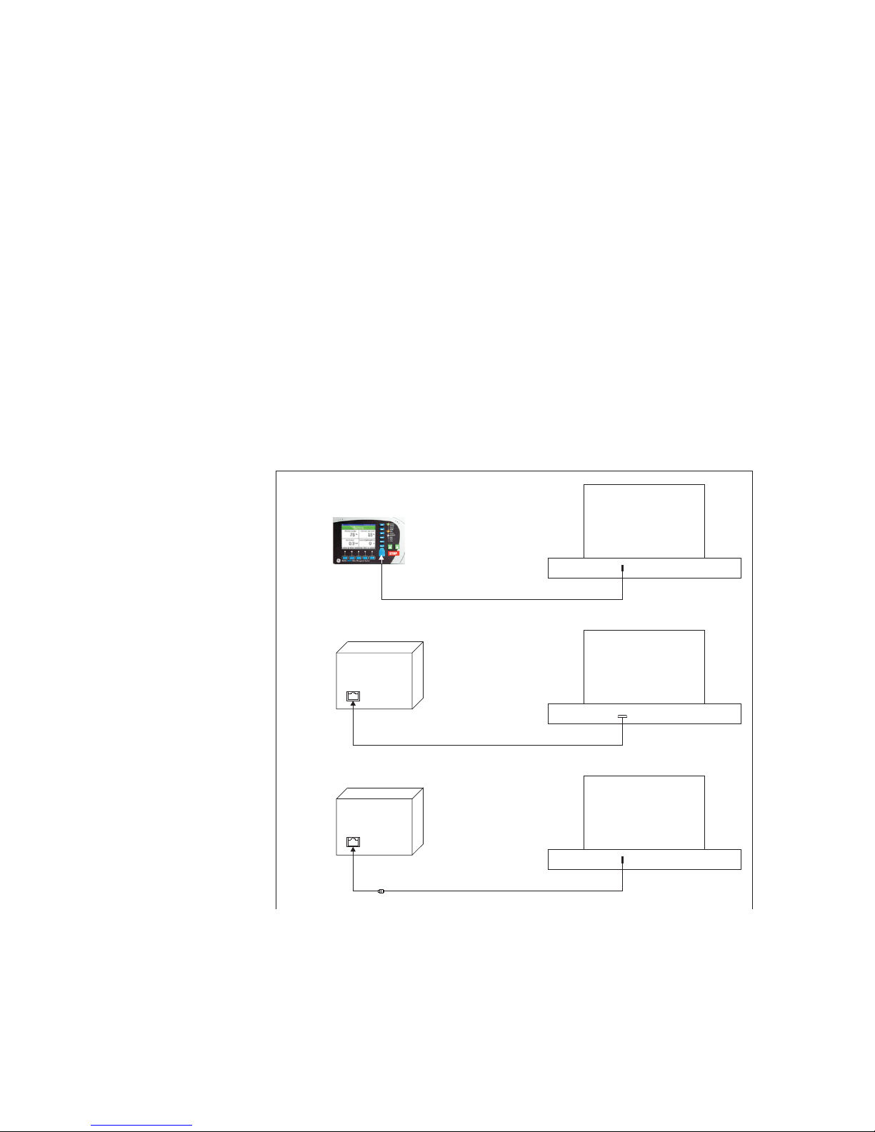
UPGRADING RELAY FIRMWARE CHAPTER 2: INSTALLATION
USB
Port
USB Port
PC
RS 485 TO
CONTROL
PANEL
PSU
USB-to-Serial converter cable
RS232-to-RJ45 cable (COM10)
USB
Port
RS232 Port (COM1)
PC
RS 485 TO
CONTROL
PANEL
PSU
RS232-to-RJ45 cable
USB (Mini-B)-to-USB (Type-A) cable
(3)
(2)
(1)
USB Port
PC
If there is no RS232 port on your PC:
1.1. If you are using the MM300 Graphical Control Panel (GCP) or Hand Held
Device (HHD), connect the USB port on the front of the MM300 relay, to the USB
port on the local PC, using a USB 2.0 type A to mini B cable. This configuration
(1) is shown below.
1.2. If you are using the Basic Control Panel (BCP), and your PC has an RS232 port,
disconnect the existing RJ45 cable from the side of the base unit (labelled
"RS485 to Control Panel"), and connect an RS232-to-RJ45 cable from the PC to
that same RJ45 port on the side of the base unit. This configuration (2) is shown
below.
1.3. If you are using no control panel, and your PC has an RS232 port, connect an
RS232-to-RJ45 cable from the PC to the RJ45 port on the side of the base unit
(labelled "RS485 to Control Panel"). This configuration (2) is shown below.
Note 1: If your PC does not have an RS232 port, you will have to use a USB-to-serial
converter cable (p/n 0100-0001), available at the GE Online Store (http://
www.gegridsolutions.com). This configuration (3) is shown below.
Note 2: If the unit does not have Graphical Control Panel (GCP), you will have to use a
RS232 to RJ45 custom cable (p/n 0804-0180), available at the GE Online Store (http://
www.gegridsolutions.com).
Note 3: If you use a USB-to-serial converter cable (see Note 1 above), the effective
COM port for this configuration, will be COM10 as shown below.
40 MM300 MOTOR MANAGEMENT SYSTEM – QUICKSTART GUIDE
Page 50
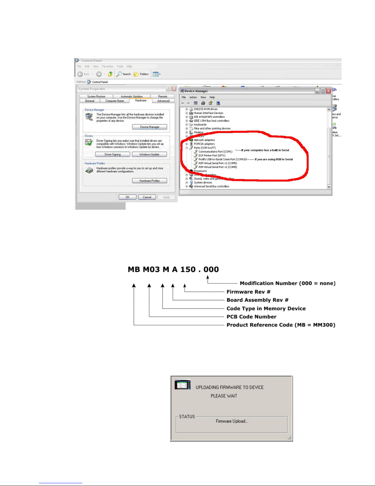
CHAPTER 2: INSTALLATION UPGRADING RELAY FIRMWARE
2. Click Windows Start Button > Control Panel > System > Hardware tab. Then click
Device Manager. Once your physical connections are complete and you have
determined which COM PORT you will be using, start your MM300/MM200 EnerVista
Setup Program.
3. Save the setpoints to a file as shown in Downloading and Saving Setpoints Files.
4. Select the Maintenance > Update Firmware menu item.
5. The EnerVista MM300/MM200 Setup software will request the location of the folder
containing the new firmware file. Locate the folder that contains the firmware files to
load into the MM300 MM300 . The firmware filename has the following format:
6. EnerVista MM300/MM200 Setup EnerVista MM300/MM200 Setup software now
prepares the MM300 to receive the new firmware file.
7. While the file is being loaded into the MM300 MM300 , a status box appears showing
how much of the new firmware file has been transferred and the upgrade status. The
entire transfer process takes approximately 10 minutes.
MM300 MOTOR MANAGEMENT SYSTEM – QUICKSTART GUIDE 41
Page 51

UPGRADING RELAY FIRMWARE CHAPTER 2: INSTALLATION
8. The EnerVista MM300/MM200 Setup software will notify the user when the
MM300 MM300 has finished loading the file. Carefully read any displayed messages
and click OK to return the main screen. Cycling power to the relay is recommended
after a firmware upgrade.
After successfully updating the MM300 firmware, the relay will not be operational and will
require setpoint programming. To communicate with the relay, the communication
settings may have to be manually reprogrammed.
When communications are established, the saved setpoints must be reloaded back into
the relay. See Loading Setpoints from a File for details.
Modbus addresses assigned to firmware modules, features, settings, and corresponding
data items (i.e. default values, min/max values, data type, and item size) may change
slightly from version to version of the firmware. Addresses are rearranged when new
features are added or existing features are enhanced or modified.
42 MM300 MOTOR MANAGEMENT SYSTEM – QUICKSTART GUIDE
Page 52

GE
Grid Solutions
MM300 Motor Management System
Chapter 3: Actual values
Actual values overview
Actual values
Measured values, maintenance and fault analysis information are accessed in the actual
values screens. Actual values may be accessed via one of the following methods.
• Through the graphical control panel, using the keys and display.
• With the EnerVista MM300 Setup software supplied with the relay.
• Through the RS485 or Ethernet ports and a PLC/SCADA system running user-written
software.
Actual value messages are organized into logical groups, or pages, for easy reference.
Pressing the Values soft-key displays the actual values summary window. A summary of
metered current, voltage, and power values are shown for all three phases.
Figure 3-1: Actual values summary window
MM300 MOTOR MANAGEMENT SYSTEM – QUICKSTART GUIDE 1
Page 53

ACTUAL VALUES OVERVIEW CHAPTER 3: ACTUAL VALUES
2 MM300 MOTOR MANAGEMENT SYSTEM – QUICKSTART GUIDE
Page 54
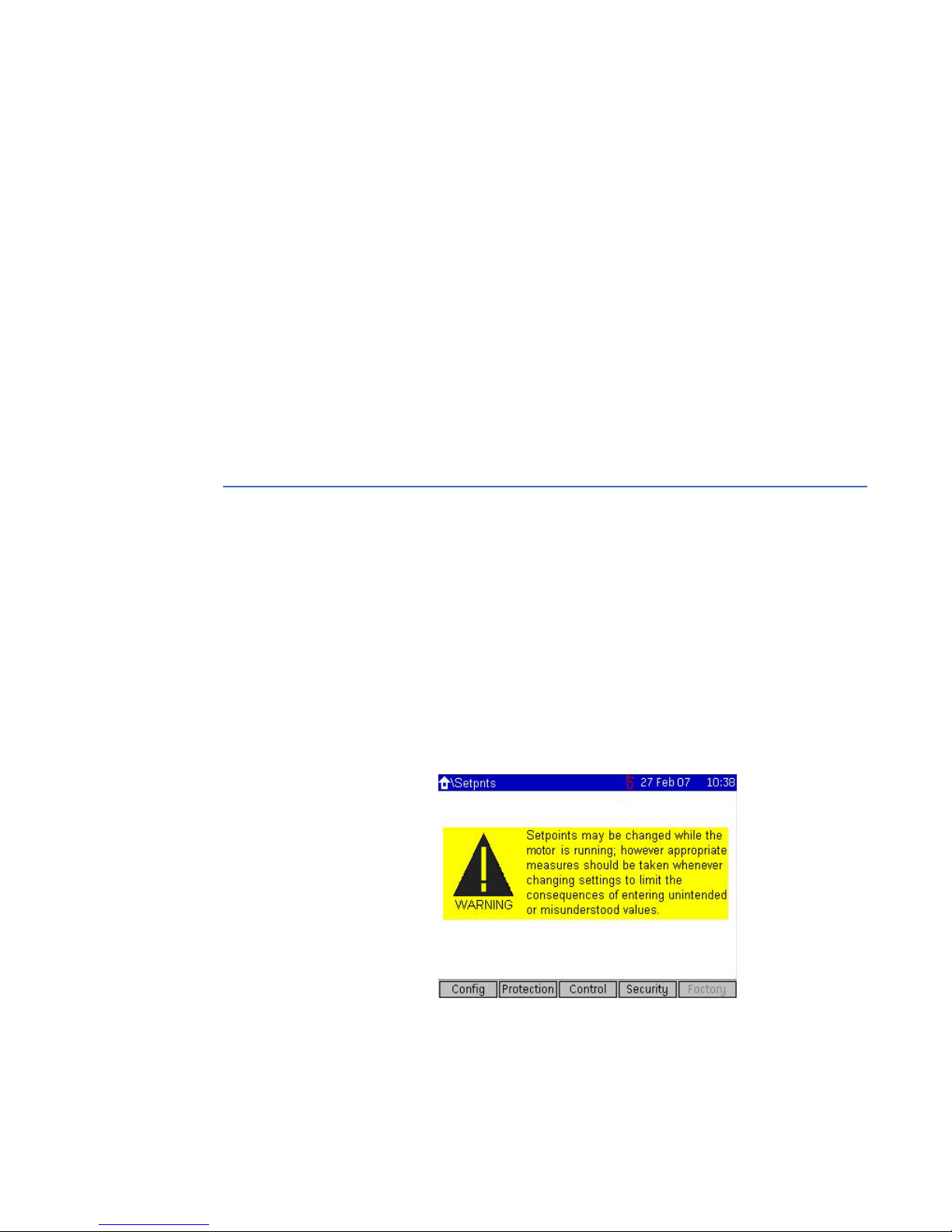
GE
Grid Solutions
MM300 Motor Management System
Chapter 4: Setpoints
Understanding setpoints
Setpoints
Any of the motor trip and alarm setpoints may be viewed or altered by pressing the
Setpoints soft-key. Setpoints data is divided into four pages.
• Configuration page: Information about the motor configuration as well as system
setup, inputs, outputs, communications, CTs, and VTs.
• Protection page: Information about the protection features.
• Control page: Information about the process control features.
• Security page: Information about the security and password features.
Press the Setpoint soft-key to scroll through the setpoints pages. When pressed for the
first time, the following screen is displayed.
Figure 4-1: Setpoints home page
The soft-keys on the Home > Setpoints page open pages two levels down, since the pages
immediately below this page are blank. For example, the Config soft-key opens the Home
> Setpoints > Config > Motor page.
MM300 MOTOR MANAGEMENT SYSTEM – QUICKSTART GUIDE 1
Page 55

CONFIGURATION SETPOINTS CHAPTER 4: SETPOINTS
NOTE
The pages containing setpoint fields, except for the inputs and outputs pages, are in a
common format. This is a simple tabular format with two columns: setpoint name and
units, and setpoint value. Setpoints for features that are not enabled are omitted from the
page.
CAUTION:
Setpoints may be changed while the motor is running; however it is not recommended
to change important protection parameters without first stopping the motor.
Setpoints will remain stored indefinitely in the internal non-volatile memory even when
control power to the unit is removed. Protection parameters are based on the entered
data. This data must be complete and accurate for the given system for reliable protection
and operation of the motor.
Configuration setpoints
The configuration setpoints contains data on motor configuration as well as system setup,
inputs, outputs, communications, CTs, and VTs. The following sub-pages are available.
• Motor (setpoints related to motor configuration).
• CT-VT (setpoints related to CT and VT configuration).
• Inputs (setpoints related to digital input configuration)
• Outputs (setpoints related to digital output configuration)
• Comms (setpoints related to communications configuration)
• System (setpoints related to MM300 system configuration, such as the faceplate
LEDs)
• Events (setpoints related to the event recorder)
• Counters (setpoints related to the digital counters)
Motor setpoints
The MM300 starter function is responsible for executing the motor startup sequence,
including the pre-contactor start warning. The MM300 provides eight pre-defined starters.
• Full-voltage non-reversing
• Full-voltage reversing
• Two-speed
• Wye-delta open transition
•Inverter
•Soft start
• Autotransformer open transition
• Autotransformer closed transition
NOTE:
By selecting a pre-defined starter, inputs and outputs are automatically assigned.
Select the Home > Setpoints > Config > Motor page to edit the motor data settings.
2 MM300 MOTOR MANAGEMENT SYSTEM – QUICKSTART GUIDE
Page 56

CHAPTER 4: SETPOINTS CONFIGURATION SETPOINTS
Figure 4-2: Motor data settings page
Common motor
setpoints
Several motor setpoints are dependent on the chosen starter type. The setpoints shown
below are common to all starter types.
Motor Name
Range: up to 20 alphanumeric characters
Default: Motor Name
This setpoint specifies a name for the motor. This name will appear in the actual values,
sequence of events record, and other reports.
Starter Type (Mandatory Setpoint)
Range: None, FV Non-Reversing, FV Reversing, Two Speed, Wye-Delta, Inverter, Soft
Starter, Autotr Open Trans, Autotr Closed Trans, Custom Starter
Default: FV Non-Reversing
This setpoint selects the starter type. The relay is essentially disabled when the value is
set to “None”. The following figure illustrates typical starter timing beginning from the
stopped state for all starter types.
Motor FLA (Mandatory Setpoint)
Range: 0.5 to 1000.0 amps in steps of 0.1
Default: OFF
This setpoint must be specified for motor protection. The value may be taken from the
motor nameplate data sheets.
Motor Nameplate Voltage (Mandatory Setpoint)
Range: 100 to 690 volts in steps of 1
Default: 690 volts
This setpoint specifies the rated motor nameplate voltage. This value represents the
base phase-to-phase voltage, and is used by the undervoltage and overvoltage
protection elements.
Supply Frequency (Mandatory Setpoint)
Range: 50 Hz, 60 Hz
Default: 60 Hz
This setpoint specifies the nominal system frequency.
Motor Rating (Mandatory Setpoint)
Range: 0.3 to 1100.0 kW in steps of 0.1 or OFF
Default: OFF
This setpoint specifies the motor rating (or low speed motor rating for two-speed
starters) in kWs.
MM300 MOTOR MANAGEMENT SYSTEM – QUICKSTART GUIDE 3
Page 57

CONFIGURATION SETPOINTS CHAPTER 4: SETPOINTS
Contactor B Relay
Contactor A Relay
Pre-contactor
Starting
Running
Start A
Start B
Start A
Stop
Motor Current
Full Voltage Non-reversing
Contactor B Relay
Contactor A Relay
Pre-contactor
Starting
Running
Motor Current
Full Voltage Reversing
Contactor B Relay
Contactor A Relay
Pre-contactor
Starting
Running
Motor Current
Two Speed Starter
Contactor B Relay
Contactor A Relay
Pre-contactor
Starting
Running
Motor Current
Wye-Delta Starter
Contactor B Relay
Contactor A Relay
Pre-contactor
Starting
Running
Motor Current
Inverter Starter and Soft Starter
Stopping
P
T
P
P
P
P
T
T
T
R
P - Pre-contactor Time setting
T - Transfer Time setting
R - Ramp Down Time setting
853710A2.CDR
1s
Figure 4-3: Typical starter timing (1 of 2)
4 MM300 MOTOR MANAGEMENT SYSTEM – QUICKSTART GUIDE
Page 58
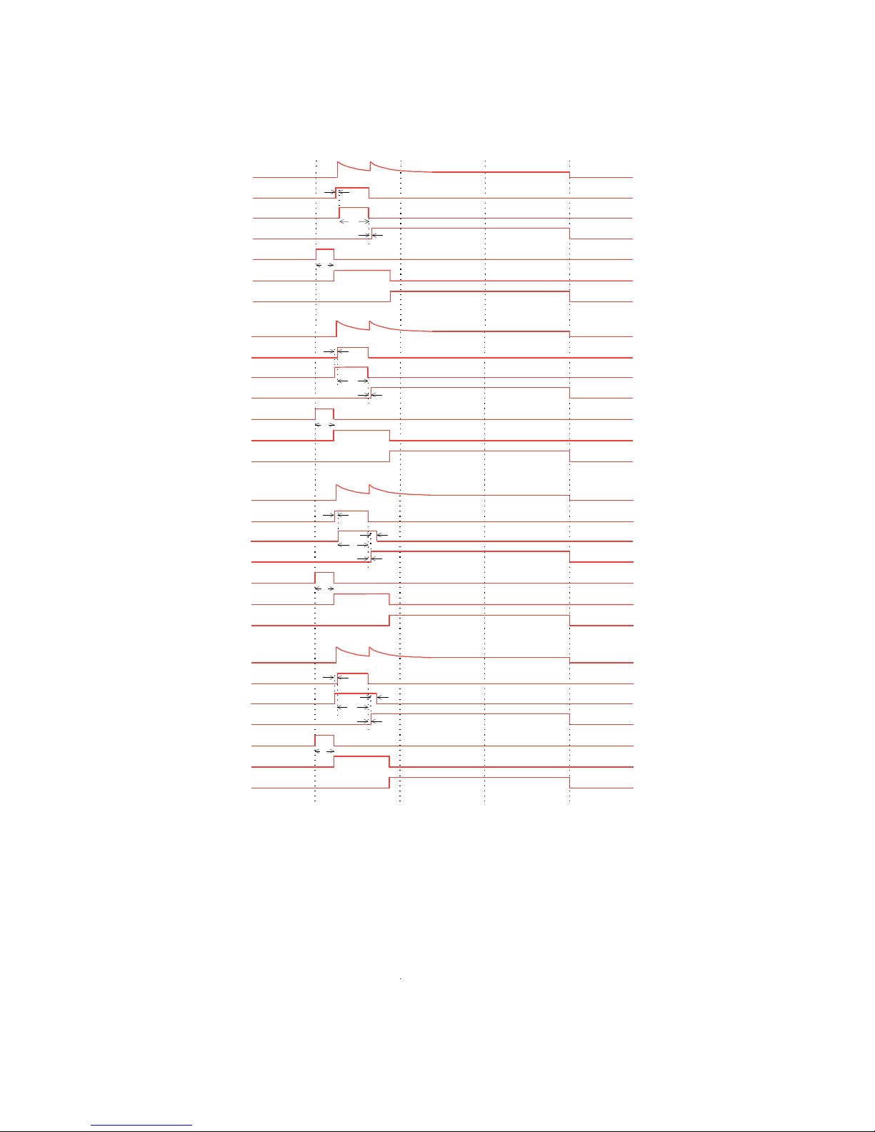
CHAPTER 4: SETPOINTS CONFIGURATION SETPOINTS
Start A
Start B
Start A
Stop
P - Pre-contactor Time setting
T - Transfer Time setting
R - Ramp Down Time setting
853856A1.CDR
Contactor B relay
Contactor A relay
Pre-contactor
Starting
Running
Motor current
P
T
Contactor C relay
~20 ms
~20 ms
Autotransformer Open Transition 1S-2S
Contactor B relay
Contactor A relay
Pre-contactor
Starting
Running
Motor current
P
T
Contactor C relay
~20 ms
~20 ms
Autotransformer Open Transition 2S-1S
Contactor B relay
Contactor A relay
Pre-contactor
Starting
Running
Motor current
P
T
Contactor C relay
~20 ms
~40 ms
~40 ms
Autotransformer Closed Transition 1S-2S
Contactor B relay
Contactor A relay
Pre-contactor
Starting
Running
Motor current
P
T
Contactor C relay
~20 ms
~40 ms
~40 ms
Autotransformer Closed Transition 2S-1S
Figure 4-4: Typical starter timing (2 of 2)
The following sections provide additional information for each starter type.
MM300 MOTOR MANAGEMENT SYSTEM – QUICKSTART GUIDE 5
Page 59
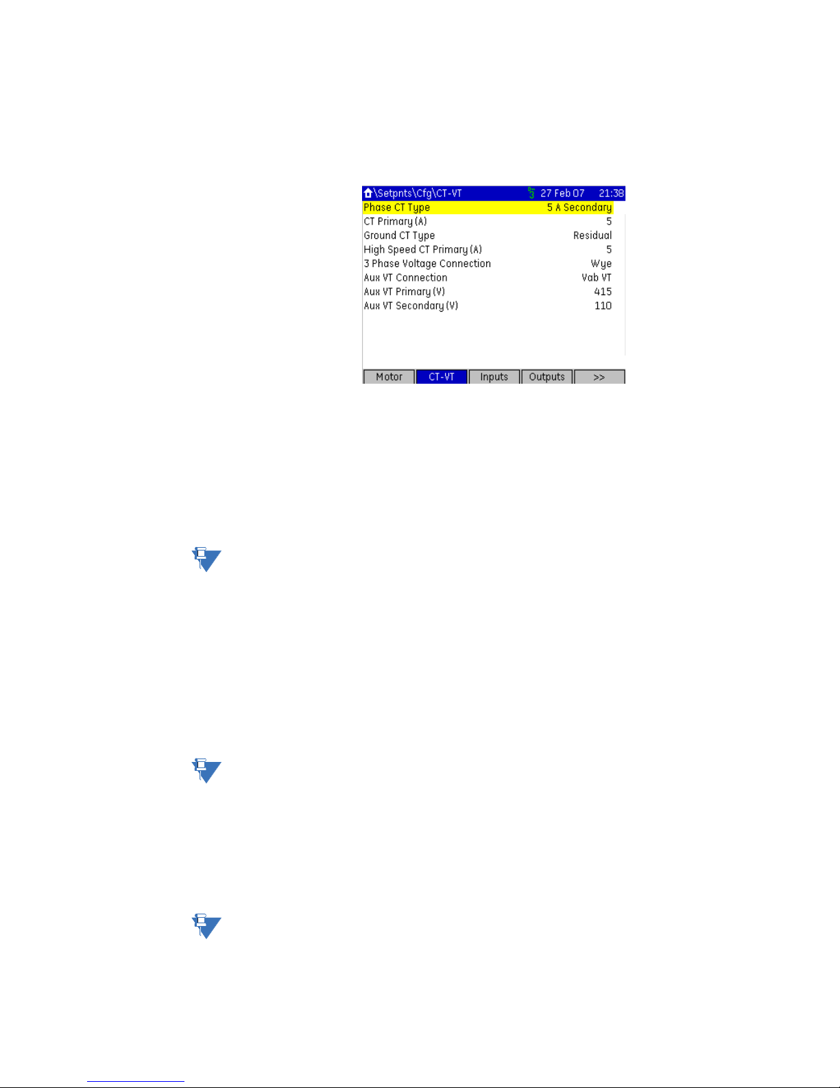
CONFIGURATION SETPOINTS CHAPTER 4: SETPOINTS
NOTE
Current and voltage transformers
Select the Home > Setpoints > Config > CT-VT page to edit the current and voltage
transformer setpoints.
Figure 4-5: Typical current and voltage transformer setpoints window
The following setpoints are available to configure the current and voltage transformers.
Phase CT Type (Mandatory Setpoint)
Range: None, 1 A Secondary, 5 A Secondary, Direct Connect
Default: Direct Connect
This setpoint specifies the phase CT connection type. The “Direct Connect” value
indicates that no phase CTs are used; instead, motor phase current passes directly
through the relay. The “Direct Connect” selection should never be used where full load
current is greater than 5.0 amps.
NOTE:
If Direct Connect is selected and the FLA is set >5 A, a "FLA too high" message will be
displayed on the Status page.
CT Primary (Mandatory Setpoint)
Range: 5 to 1000 amps in steps of 1
Default: 5 amps
This setpoint specifies the phase CT primary current. It should never be less than the full
load current, and preferably no greater than twice than the full load current.
Standard cut-off default is 20% (0.2pu) of CT primary. At CT primary less then 0.2pu,
primary CT turns are required and an appropriate current cut-off setpoint.
For example: using a 30:1 CT with 6A FLA gives 0.2A CT secondary @ FLA, the cut-off
must be lowered to 0.1A and a minimum of 3 primary turns are required.
NOTE:
This setpoint is displayed only if the phase CT type is set to 1 A secondary or 5 A
secondary.
High Speed CT Primary
Range: 5 to 1000 amps in steps of 1
Default: 5 amps
This setpoint specifies the phase CT primary current when the motor is running at high
speed. It should never be less than the high speed full load current, and preferably no
greater than twice than the high speed full load current.
NOTE:
This setpoint is displayed only if the phase CT type is set to 1 A secondary or 5 A
secondary and the motor starter type is two-speed.
6 MM300 MOTOR MANAGEMENT SYSTEM – QUICKSTART GUIDE
Page 60

CHAPTER 4: SETPOINTS CONFIGURATION SETPOINTS
Ground CT Type
Range: None, Residual, CBCT 2000:1
Default: CBCT 2000:1
This setpoint specifies the type of ground CT. Select "Residual" if the fourth CT Input on
the IO_A is connected to the residual of the Phase CT. Select 2000:1 if a zero sequence CT
(CBCT) is connected to the ground input on the CPU card.
CT Primary Turns
Range: 1 to 10
Default: 1
For smaller motors where the drawn current is very low, the motor leads may be
wrapped through the CT Primary with several turns thereby increasing the current seen
by the MM300 and as a result increasing the accuracy of the measurement. The value of
this setting should equal the number of turns on the CT Primary to display the correct
current value. Internally the current measurement will be divided by this setting.
Standard cut-off default is 20% (0.2pu) of CT primary. At CT primary less then 0.2pu,
primary CT turns are required and an appropriate current cut-off setpoint.
For example: using a 30:1 CT with 6A FLA gives 0.2A CT secondary @ FLA, the cut-off
must be lowered to 0.1A and a minimum of 3 primary turns are recommended.
Three Phase Voltage Connection
Range: Wye, Delta
Default: Wye
The method in which the IO_B voltage inputs are connected must be entered here. Note
that phase reversal is disabled for single VT operation. All voltages are assumed
balanced.
Auxiliary Voltage Connection (Mandatory Setpoint)
Range: VabVT, VbcVT, VcaVT, VanVT, VbnVT, VcnVT, VanDirect , VbnDirect, VcnDirect
Default: Vab VT
This setpoint specifies the control transformer connection to the motor supply voltage.
Auxiliary VT Primary
Range: 110 to 690 volts in steps of 1
Default: 415 volts
This setpoint specifies the primary voltage rating of the control transformer.
Auxiliary VT Secondary
Range: 110 to 300 volts in steps of 1
Default: 110 volts
This setpoint specifies the secondary voltage rating of the control transformer.
MM300 MOTOR MANAGEMENT SYSTEM – QUICKSTART GUIDE 7
Page 61

CONFIGURATION SETPOINTS CHAPTER 4: SETPOINTS
8 MM300 MOTOR MANAGEMENT SYSTEM – QUICKSTART GUIDE
Page 62

GE
Grid Solutions
MM300 Motor Management System
Chapter 5: Protection elements
Thermal protection
Protection elements
The primary protective function of the MM300 is the thermal model. The MM300 integrates
stator and rotor heating into a single model. The rate of motor heating is gauged by
measuring the terminal currents. The present value of the accumulated motor heating is
maintained in the
overload, the motor temperature and thermal capacity used will rise. A trip occurs when
the thermal capacity used reaches 100%. When the motor is stopped and is cooling to
ambient, the thermal capacity used decays to zero. If the motor is running normally, the
motor temperature will eventually stabilize at some steady state temperature, and the
thermal capacity used increases or decreases to some corresponding intermediate value,
which accounts for the reduced amount of thermal capacity left to accommodate
transient overloads.
The thermal model consists of six key elements.
• Unbalance current biasing that accounts for negative-sequence heating.
• Hot/cold biasing that accounts for normal temperature rise.
• RTD biasing that accounts for ambient variation and cooling problems
• An overload curve that accounts for the rapid heating that occurs during stall,
acceleration, and overload.
• Cooling rate that accounts for heat dissipation.
• Thermal protection reset that controls recovery from thermal trips and lockouts.
Each of these categories are described in the following sub-sections.
Overload curve
The overload curve accounts for the rapid motor heating that occurs during stall,
acceleration, and overload. Specifically, the overload curve controls the rate of increase of
Thermal Capacity Used whenever the equivalent motor heating current is greater than
1.01 times the full load current setpoint. The curve is defined by the following equation and
Thermal Capacity Used actual value register. When the motor is in
MM300 MOTOR MANAGEMENT SYSTEM – QUICKSTART GUIDE 1
Page 63

THERMAL PROTECTION CHAPTER 5: PROTECTION ELEMENTS
´
=
Curve Multiplier
timeTrip
2.2116623
0.02530337 x (Pickup - 1) + 0.05054758 x (Pickup -1)
2
reflects that overload heating largely swamps the cooling, and this heating is primarily due
to resistive losses in the stator and the rotor windings (said losses being proportional to the
square of the current).
Eq. 1
In the above equation,
• The trip time represents the time (in seconds) for the MM300 to trip, given the motor
starts cold and the current is constant.
• The multiplier represents the value of the Curve Multiplier setpoint. This setpoint can
be used to adjust the curve to match the thermal characteristics of the motor.
• Ieq represents the equivalent motor heating current in per-unit values on a full load
current base. The value of I
is limited in this equation to 8.0 to prevent the overload
eq
from acting as an instantaneous element and responding to short circuits. Equivalent
motor heating current is discussed in the Unbalance biasing section.
For example, a motor with a stall current (also known as locked rotor current) of 8 times its
FLA, with a curve multiplier of 7, if stalled from a cold state, trips in the following amount of
time.
This would respect a safe stall cold time of 10 seconds.
The standard overload curves are displayed below.
Eq. 2
2 MM300 MOTOR MANAGEMENT SYSTEM – QUICKSTART GUIDE
Page 64

CHAPTER 5: PROTECTION ELEMENTS THERMAL PROTECTION
x1
x15
100000
10000
1000
100
10
1.00
0.10
1.00
MULTIPLE OF FULL LOAD AMPS
TIME IN SECONDS
10
100
1000
806804A5.CDR
Figure 5-1: Standard overload curves
The trip times for the standard overload curves are tabulated below.
Table 5-1: Standard overload curve trip times (in seconds)
PIC
STANDARD CURVE MULTIPLIERS
KUP
× 1 × 2 × 3 × 4 × 5 × 6 × 7 × 8 × 9 × 10 × 11 × 12 × 13 × 14 × 15
(× F
LA)
1.014353.68707.21306117414217682612230475348293918343536478905224356597609516530
1.05853.711707.42561.13414.94268.65122.35976.06829.77683.48537.19390.81024511098119521280
1.10416.68833.361250.01666.72083.42500.12916.83333.53750.14166.84583.55000.25416.95833.66250
1.20198.86397.72596.58795.44994.301193.21392.01590.91789.71988.62187.52386.32585.22784.12982
1.30126.80253.61380.41507.22634.02760.82887.631014.41141.21268.01394.81521.61648.51775.31902
1.4091.14182.27273.41364.55455.68546.82637.96729.09820.23911.371002.51093.61184.81275.91367
1.5069.99139.98209.97279.96349.95419.94489.93559.92629.91699.90769.89839.88909.87979.861049
4
6
.2
.9
.1
.0
.9
MM300 MOTOR MANAGEMENT SYSTEM – QUICKSTART GUIDE 3
Page 65

THERMAL PROTECTION CHAPTER 5: PROTECTION ELEMENTS
PIC
STANDARD CURVE MULTIPLIERS
KUP
× 1 × 2 × 3 × 4 × 5 × 6 × 7 × 8 × 9 × 10 × 11 × 12 × 13 × 14 × 15
(× F
LA)
1.7542.4184.83127.24169.66212.07254.49296.90339.32381.73424.15466.56508.98551.39593.81636.
2.0029.1658.3287.47116.63145.79174.95204.11233.26262.42291.58320.74349.90379.05408.21437.
2.2521.5343.0664.5986.12107.65129.18150.72172.25193.78215.31236.84258.37279.90301.43322.
2.5016.6633.3249.9866.6483.3099.96116.62133.28149.94166.60183.26199.92216.58233.24249.
2.7513.3326.6539.9853.3166.6479.9693.29106.62119.95133.27146.60159.93173.25186.58199.
3.0010.9321.8632.8043.7354.6665.5976.5287.4698.39109.32120.25131.19142.12153.05163.
3.259.15 18.2927.4436.5845.7354.8764.0273.1682.3191.46100.60109.75118.89128.04137.
3.507.77 15.5523.3231.0938.8746.6454.4162.1969.9677.7385.5193.28101.05108.83116.
3.756.69 13.3920.0826.7833.4740.1746.8653.5660.2566.9573.6480.3487.0393.73100.
4.005.83 11.6617.4923.3229.1534.9840.8146.6452.4758.3064.1369.9675.7981.6287.4
4.255.12 10.2515.3720.5025.6230.7535.8741.0046.1251.2556.3761.5066.6271.7576.8
4.504.54 9.08 13.6318.1722.7127.2531.8036.3440.8845.4249.9754.5159.0563.5968.1
4.754.06 8.11 12.1716.2220.2824.3328.3932.4436.5040.5544.6148.6652.7256.7760.8
5.003.64 7.29 10.9314.5718.2221.8625.5029.1532.7936.4340.0843.7247.3651.0154.6
5.502.99 5.98 8.97 11.9614.9517.9420.9323.9126.9029.8932.8835.8738.8641.8544.8
6.002.50 5.00 7.49 9.99 12.4914.9917.4919.9922.4824.9827.4829.9832.4834.9737.4
6.502.12 4.24 6.36 8.48 10.6012.7214.8416.9619.0821.2023.3225.4427.5529.6731.7
7.001.82 3.64 5.46 7.29 9.11 10.9312.7514.5716.3918.2120.0421.8623.6825.5027.3
7.501.58 3.16 4.75 6.33 7.91 9.49 11.0812.6614.2415.8217.4118.9920.5722.1523.7
8.001.39 2.78 4.16 5.55 6.94 8.33 9.71 11.1012.4913.8815.2716.6518.0419.4320.8
22
37
96
90
91
98
18
60
42
5
7
4
3
5
4
7
9
2
4
2
The following tables illustrate the relation between GE Multilin MM2 and MM3 curve
numbers, NEMA curves, and the MM300 curve multipliers.
Table 5-2: MM2 and MM3 curve numbers and MM300 curve multipliers
MM2 and MM3 curve number 1 2 3 4 5 6 7 8
MM300 curve multiplier 1 2 3 4 7 9 12 15
Table 5-3: NEMA curves and MM300 curve multipliers
NEMA curve Class 10 Class 15 Class 20 Class 30
MM300 curve multiplier 4 6 8 12
4 MM300 MOTOR MANAGEMENT SYSTEM – QUICKSTART GUIDE
Page 66

GE
Grid Solutions
MM300 Motor Management System
Chapter 6: Communications
Communications interfaces
Communications
The MM300 has three communications interfaces. These can be used simultaneously:
• RS485
• 10/100Base-T Ethernet
•Fieldbus
NOTE:
NOTE:
NOTE:
Setpoint changes related to DeviceNet, Profibus, and Ethernet, require a power cycle to be
activated.
External power must be present on the Fieldbus port at power-up, in order to correctly
initialize and operate.
For full details, please refer to the MM300 Communications Guide, to be found on the GE
Multilin web site.
MM300 MOTOR MANAGEMENT SYSTEM – QUICKSTART GUIDE 1
Page 67

COMMUNICATIONS INTERFACES CHAPTER 6: COMMUNICATIONS
2 MM300 MOTOR MANAGEMENT SYSTEM – QUICKSTART GUIDE
Page 68

GE
NOTE
Grid Solutions
MM300 Motor Management System
Chapter 7: Specifications
NOTE:
Specifications
Specifications are subject to change without notice.
Protection specifications
ACCELERATION TIMER
Pickup:......................................................................Iav > I
Dropout: ..................................................................Iav < Ipu or timer expired
Time delay: ............................................................ 0.5 to 250.0 seconds in steps of 0.1
Timing accuracy:................................................ ±500 ms or 1.5% of total time
Elements: ................................................................ trip and alarm
AUXILIARY UNDERVOLTAGE
Pickup level:........................................................... 60 to 90% of NCV
Time delay: ............................................................ 1 to 60 seconds in steps of 1
Timing accuracy:................................................ ± 500 ms
Elements: ................................................................ trip and alarm
CURRENT UNBALANCE
Range: ...................................................................... 4 to 40% in steps of 1
Accuracy:................................................................ ±2%
Time delay: ............................................................ 1 to 60 seconds in steps of 1 s
Timing accuracy:................................................ ±500 ms
Elements: ................................................................ trip and alarm
pu
CALCULATION METHOD
If I
If I
Where:
I
AV
I
M
I
FLA
MM300 MOTOR MANAGEMENT SYSTEM – QUICKSTART GUIDE 1
≥ I
: ( [IM - IAV] /IAV ) x 100%
AV
FLA
≤ I
: ( [IM - IAV] /I
AV
FLA
= average phase current
= current in a phase with maximum deviation from I
= MOTOR FULL LOAD CURRENT setpoint
) x 100%
FLA
AV
Page 69

PROTECTION SPECIFICATIONS CHAPTER 7: SPECIFICATIONS
FUSE FAILURE (RUNNING STATE ONLY)
Timing: ..................................................................... <500 ms
Elements:................................................................ trip and alarm
GROUND FAULT (CBCT OR RESIDUAL)
Pickup level:........................................................... 0.5 to 15.0 A in steps of 0.1 (CBCT); 10 to 100% of FLA in
steps of 1% (residual)
Trip time delay on start: .................................. 0 to 10 s in steps of 0.1 s
Trip time delay on run:..................................... 0 to 5 s in steps of 0.1 s
Alarm time delay on start/run:..................... 0 to 60 s in steps of 1 s
Timing accuracy:................................................ ±50 ms or ±0.5% of total time
Elements:................................................................ trip and alarm
LOAD INCREASE
Pickup level:........................................................... 50 to 150% of FLA in steps of 1%
Timing accuracy:................................................ ±500 ms
Elements:................................................................ Alarm
MECHANICAL JAM
Pickup level:........................................................... 1.01 to 4.50 × FLA in steps of 0.01
Time delay:............................................................ 0.1 to 30.0 seconds in steps of 0.1
Timing accuracy:................................................ ±500 ms
Elements:................................................................ trip
PHASE OVERVOLTAGE
Pickup level:........................................................... 101 to 120% of rated in steps of 1%
Time delay:............................................................ 1 to 60 seconds in steps of 1 s
Timing accuracy:................................................ ±500 ms
Elements:................................................................ trip and alarm
PHASE UNDERVOLTAGE
Pickup level:........................................................... 60 to 99% of rated in steps of 1
Time delay:............................................................ 1 to 60 seconds in steps of 1 s
Timing accuracy:................................................ ±500 ms
Elements:................................................................ trip and alarm
RTD PROTECTION
RTD types:.............................................................. three-wire (100 ohm Platinum)
Range:...................................................................... –50 to 250°C in steps of 1
Hysteresis: ............................................................. 2°C
THERMAL MODEL
Standard curve time multiplier: ................... 1 to 15 in steps of 1
Thermal overload pickup:............................... 1.01 to 1.25 in steps of 0.01
Motor full load current (FLA): ......................... 0.5 to 1000 A in steps of 0.1
Motor rated voltage: ......................................... 100 to 690 V AC
Curve biasing:....................................................... phase unbalance (±5%) hot/cold ratio stator RTD
exponential running and stopped cooling rates
Update rate:.......................................................... 3 cycles
Hot/cold safe stall ratio:.................................. 1 to 100% in steps of 1%
Timing accuracy:................................................ ±200 ms or ±2% of total time (based on measured value)
Elements:................................................................ trip and alarm
THERMISTOR
Sensor types:........................................................ PTC (R
Timing accuracy:................................................ ±500 ms
Elements:................................................................ Trip and alarm
= 100 to 30 kohms); NTC (R
HOT
= 100 to 30 kohms)
HOT
UNDERCURRENT
Pickup level:........................................................... 1 to 100% of FLA in steps of 1
Time delay:............................................................ 1 to 60 seconds in steps of 1
Timing accuracy:................................................ ±500 ms
Elements:................................................................ trip and alarm
2 MM300 MOTOR MANAGEMENT SYSTEM – QUICKSTART GUIDE
Page 70

CHAPTER 7: SPECIFICATIONS USER INTERFACE SPECIFICATIONS
UNDERPOWER
Pickup level:........................................................... 1 to 100% of kW rating in steps of 1
Time delay: ............................................................ 1 to 60 seconds in steps of 1
Timing accuracy:................................................ ±500 ms
Elements: ................................................................ trip and alarm
VOLTAGE PHASE REVERSAL
Configuration:....................................................... ABC or Rev starter
Timing accuracy:................................................ ±500 ms
Elements: ................................................................ trip or alarm
User interface specifications
GRAPHICAL CONTROL PANEL AND HAND HELD DEVICE
Size: ........................................................................... width 153mm, height 102mm, depth 35mm
LCD: ........................................................................... 3.5-inch color, 320 by 240 pixels
LED indicators: ..................................................... 10 LEDs
Pushbuttons:......................................................... Start A, Start B, Stop, plus 11 LCD screen display control keys
Ports:......................................................................... USB 2.0 port for laptop computer connection
Cable - GCP to Base Unit:................................ Shielded RJ45; Maximum length 6’ (1.83 m)
BASIC CONTROL PANEL
Size: ........................................................................... BCP: width 75mm, height 75mm, depth 31mm
LCD: ........................................................................... 3.5-inch color, 320 by 240 pixels
LED indicators: ..................................................... 12 LEDs
Pushbuttons:......................................................... Start A, Start B, Stop, Reset, Auto, Manual
Cable - BCP to Base Unit: ................................ Shielded RJ45; Maximum length 6’ (1.83 m)
Metering and monitoring specifications
EVENT RECORDER
Capacity:................................................................. 256 events
Data storage:........................................................ non-volatile memory
FREQUENCY METERING
Range: ...................................................................... 40.00 to 70.00 Hz in steps of 0.01
Accuracy:................................................................ ±0.05 Hz
POWER METERING
Real power range: .............................................. –2000.0 to 2000.0 kW in steps of 0.1
Apparent power range:.................................... 0.0 to 2500.0 kVA in steps of 0.1
Accuracy:................................................................ ±1% of full scale
POWER FACTOR METERING
Range: ...................................................................... –0.99 to +0.99 in steps of 0.01
Accuracy:................................................................ ±0.05
MM300 MOTOR MANAGEMENT SYSTEM – QUICKSTART GUIDE 3
Page 71

CONTROL SPECIFICATIONS CHAPTER 7: SPECIFICATIONS
Control specifications
UNDERVOLTAGE RESTART
Dropout/Pickup Level: ...................................... 60 to 100% NCV in steps of 1%
Short Dip Time: .................................................... 100 to 500 ms or OFF in steps of 10 ms
Medium Dip Time: .............................................. 0.1 to 10.0 s in steps of 0.1 s
Medium Dip Delay: ............................................ 0.2 to 90 s in steps of 0.2 s
Long Dip Time:..................................................... 0.5 to 60.0 min or OFF in steps of 0.5 min
Long Dip Delay: ................................................... 1.0 to 1200.0 s in steps of 1.0 s
Short Dip Time Accuracy:............................... ±5% of total time
Medium and Long Dip Time Accuracy:.... ±1 s or ±5% of total time, whichever is greater
Inputs specifications
AUXILIARY VOLTAGE INPUT (UNDERVOLTAGE RESTART SOURCE)
External VT primary: ......................................... 110 to 690 V AC in steps of 1 (if used)
Input range:........................................................... 60 to 300 V AC
Nominal frequency:........................................... 50 or 60 Hz
Accuracy: ............................................................... ±5% of reading
DIGITAL INPUTS (IO_C MODULE)
Fixed pickup:......................................................... 65 V AC
Recognition time:................................................ 2 cycles
Current draw at rated voltage: .................... 75 mA @ 120 V AC for 200 µs every cycle
60 mA @ 240 V AC for 800 µs every cycle
Input impedence:................................................ 1.7 kΩ
Type:......................................................................... opto-isolated inputs
External switch: ................................................... wet contact
Maximum input voltage: ................................. 300 V AC
DIGITAL INPUTS (IO_E MODULE)
Fixed pickup:......................................................... 20 V DC
Recognition time:................................................ 2 cycles
Current draw at rated voltage: .................... 7 mA @ 24 V DC
14 mA @ 48 V DC
Input impedence:................................................ 1.23 kΩ
Type:......................................................................... opto-isolated inputs
External switch: ................................................... wet contact
Maximum input voltage: ................................. 60 V DC
GROUND CURRENT INPUT (50:0.025)
CT primary:............................................................ 0.5 to 15.0 A
Nominal frequency:........................................... 50 or 60 Hz
Accuracy (CBCT):................................................. ±0.1 A (0.5 to 3.99 A)
±0.2 A (4.0 A to 15 A)
Burden: .................................................................... <8.6 mVA at 25 A
4 MM300 MOTOR MANAGEMENT SYSTEM – QUICKSTART GUIDE
Page 72

CHAPTER 7: SPECIFICATIONS OUTPUTS SPECIFICATIONS
PHASE CURRENT INPUTS (INCLUDING RESIDUAL GROUND CURRENT)
Range: ...................................................................... 0.2 to 40 A (8 × CT), direct connection up to 5 A FLA
Input type:.............................................................. Combined 1 A / 5 A
Frequency: ............................................................. 50 or 60 Hz
Accuracy:................................................................ ExtCT: ±2% of reading or ±1% of 8× CTPrimary, whichever is
greater
Direct: ±2% of reading or ±0.1 A, whichever is greater
Withstand (at 5A nominal):............................. 0.2 s at 100×
1.0 s at 50×
2.0 s at 40×
continuous at 3× rated current
Burden: .................................................................... <4 mVA at 1 A
<0.1 VA at 5 A
PHASE VOLTAGE INPUTS (THREE-PHASE VOLTAGE)
Input range:........................................................... 208 to 690 V
Nominal frequency:........................................... 50 or 60 Hz
Accuracy:................................................................ ±2% of reading, or ±1 V, whichever is greater
RTD INPUTS
Sensor type: .......................................................... Three-wire RTD (100 ohm Platinum)
Sensing current:................................................... 5 mA
Accuracy:................................................................ ±3°C
THERMISTOR INPUTS
Sensor type: .......................................................... Positive temperature coefficient PTC (R
ohms), negative temperature coefficient NTC(R
30000 ohms)
Accuracy:................................................................ ±6% of reading or ±100 ohms, whichever is greater
=100 to 30000
HOT
HOT
= 100 to
Outputs specifications
OUTPUT RELAYS
Configuration:....................................................... electromechanical form-A (IO_C) and form-C (IO_D)
Contact material: ................................................ silver-alloy
Operate time:........................................................ 10 ms
Minimum contact load:.................................... 10 mA at 5 V DC
Maximum switching rate: ............................... 300 operations per minute (no load), 30 operations per
Mechanical life:.................................................... 10 000 000 operations
Continuous current:........................................... 10 A
Make and carry for 0.2s:.................................. 30 A per ANSI C37.90
OUTPUT RELAY BREAK CAPACITY (FORM-A RELAY)
AC resistive, 120 V AC:....................................... 10 A
AC resistive, 240 V AC:....................................... 10 A
AC inductive, PF = 0.4 pilot duty:.................. 2 A
DC resistive, 30 V DC: ........................................ 10 A
OUTPUT RELAY BREAK CAPACITY (FORM-C RELAY)
AC resistive, 120 V AC:....................................... 10 A normally-open, 5 A normally-closed
AC resistive, 240 V AC:....................................... 10 A normally-open, 8 A normally-closed
AC inductive, PF = 0.4 pilot duty:.................. 2.5 A
DC resistive, 30 V DC: ........................................ 10 A
minute (load)
MM300 MOTOR MANAGEMENT SYSTEM – QUICKSTART GUIDE 5
Page 73

POWER SUPPLY SPECIFICATIONS CHAPTER 7: SPECIFICATIONS
Power supply specifications
POWER SUPPLY (HIGH PSU)
Nominal:.................................................................. 120 to 240 V AC 125 to 250 V DC
Range:...................................................................... 60 to 300 V AC (50 and 60 Hz) 84 to 250 V DC
Ride-Through:....................................................... 35 ms
POWER SUPPLY (LOW PSU)
Nominal:.................................................................. 24 to 48 V DC
Range:...................................................................... 20 to 60 V DC
Ride-Through:....................................................... 35 ms
ALL RANGES
Voltage withstand:............................................. 2 × highest nominal voltage for 10 ms
Power consumption: ......................................... 16 W typical, 25 W maximum
Communications specifications
DEVICENET (COPPER)
Modes: ..................................................................... slave (125, 250, and 500 kbps)
Connector: ............................................................. 5-pin terminal
Current Draw:....................................................... 80 mA @ 24 VDC
ETHERNET (COPPER)
Modes: ..................................................................... 10/100 MB (auto-detect)
Connector: ............................................................. RJ-45
SNTP clock synchronization error:.............. <200 ms (typical)
Protocol:.................................................................. Modbus TCP
PROFIBUS (COPPER)
Modes: ..................................................................... DPV0 slave, up to 1.5 Mbps DPV1 slave, up to 1.5 Mbps
Connector: ............................................................. 5-pin terminal
RS485 PORT
Port:........................................................................... opto-isolated
Baud rates: ............................................................ up to 115 kbps
Protocol:.................................................................. Modbus RTU, half-duplex
Maximum distance:........................................... 1200 m
Isolation: ................................................................. 2 kV
USB PORT (GRAPHIC CONTROL PANEL ONLY)
Standard specification:.................................... Compliant with both USB 2.0 and USB 1.1
Data transfer rate: ............................................. USB device emulating serial communications port at 115
kbps
6 MM300 MOTOR MANAGEMENT SYSTEM – QUICKSTART GUIDE
Page 74

CHAPTER 7: SPECIFICATIONS TESTING AND CERTIFICATION
Testing and certification
TESTING AND CERTIFICATION
Test Reference Standard Test Level
Dielectric Voltage Withstand: EN60255-5 2.3KV (1 minute)
Impulse Voltage Withstand: EN60255-5 5KV
Damped Oscillatory: IEC61000-4-18IEC60255-22-1 2.5KV CM, 1KV DM
Electrostatic Discharge: EN61000-4-2/IEC60255-22-2 Level 4
RF Immunity: EN61000-4-3/IEC60255-22-3 Level 3
Fast Transient Disturbance: EN61000-4-4/IEC60255-22-4 Class A
Surge Immunity: EN61000-4-5/IEC60255-22-5 Level 3
Conducted RF Immunity: EN61000-4-6/IEC60255-22-6 Level 3
Voltage Interruption and Ripple DC: IEC60255-11 15% ripple , 200ms
Radiated & Conducted Emissions: CISPR11 /CISPR22/ IEC60255-25 Class A
Sinusoidal Vibration: IEC60255-21-1 Class 1
Shock & Bump: IEC60255-21-2 Class 1
Power magnetic Immunity: IEC61000-4-8 Level 5
Pulse Magnetic Immunity: IEC61000-4-9 Level 4
Voltage Dip & Interruption: IEC61000-4-11 0,40,70% dips,250/300cycle
Damped Oscillatory: IEC61000-4-12 2.5KV CM, 1KV DM
Harmonics & Interharmonics: IEC61000-4-13 Class 3
Voltage Ripple: IEC61000-4-17 15% ripple
Ingress Protection: IEC60529 IP20 (base unit) , IP54
Environmental (Cold): IEC60068-2-1 -25
Environmental (Dry heat): IEC60068-2-2 70
Relative Humidity Cyclic: IEC60068-2-30 6-day variant 2
interupts
interrupts
(Control Panel)
o
C 16 hrs
o
C 16hrs
APPROVALS
CE compliance: Low voltage directive EN60255-5, EN61010-1
North America: cULus UL1053 [e83849 NKCR]
EAC Machines and Equipment TR CU 010/2011
ISO: Manufactured under a registered
EAC
The EAC Technical Regulations (TR) for Machines and Equipment apply to the Customs
Union (CU) of the Russian Federation, Belarus, and Kazakhstan
MM300 MOTOR MANAGEMENT SYSTEM – QUICKSTART GUIDE 7
Applicable Council Directive According to
EMC Directive EN50263 / EN61000-6-2/ EN61000-6-4
UL508 [e83849 NKCR]
C22.2-14 [e83849 NKCR7]
ISO9001
quality program
Page 75

PHYSICAL SPECIFICATIONS CHAPTER 7: SPECIFICATIONS
Item Description
Country of origin Spain or Canada; see label on the unit
Date of manufacture See label on the MM300 unit
Declaration of Conformity and/or Certificate of
Conformity
Available on request
Physical specifications
DIMENSIONS
Size: ........................................................................... Base: 120 mm (W) × 90 mm (H) × 113 mm (D) [+ terminals
10mm]
Expansion: 62 mm (W) × 90 mm (H) × 113 mm (D)
GCP: 153 mm (W) × 102 mm (H) × 35 mm (D)
BCP: 75 mm (W) × 75 mm (H) × 31 mm (D)
Weight (Base):....................................................... 0.75 kg
Environmental specifications
ENVIRONMENTAL SPECIFICATIONS
Ambient temperatures:
Storage/shipping: - 40
Operating: -20
* 1" around Base Unit
Humidity: Operating up to 95% (non condensing) @ 55
Altitude: 2000m (max)
Overvoltage Category: II
Ingress Protection: IP20 (Base Unit) IP54 (Control Panel)
Environmental rating: 60
Pollution Degree: II
Noise: 0 dB
o
C to 90oC *
o
C to 60oC *
per IEC60068-2-30 Variant 2, 6days)
o
C surrounding air
Type 1 (panel mount versions only)
o
C (As
8 MM300 MOTOR MANAGEMENT SYSTEM – QUICKSTART GUIDE
Page 76

GE
853702A4.PDF
NOTES: * The UV Restart feature is not supported with the Low-Voltage power supply option.
Harsh Environment Coating is a standard feature on all MM300 units.
Base Expanded
MM300 * E * * * * A * * * *
InterfaceMM300 | |||| |||| MM300 Motor Management System
Control
panel
X | | | | | | | | No control panel
B | | | | | | | | Basic control panel, no USB
G | | | | | | | | Graphical control panel with USB
Power supply H | | | | | | | High: 80 to 250 V DC (Standard); 60 to 300 V AC
L | | | | | | | Low*: 24 V DC (24 to 48 V DC Nominal)
Communications S|| |||| Standard communications: RS485 Modbus RTU
D|| |||| Standard plus DeviceNet Slave and 10/100 Modbus TCP
P|| |||| Standard plus Profibus DP Slave and 10/100 Modbus TCP
Options S | | | | | Standard: Starter control and event recorder
1 | | | | | Option 1: Standard plus undervoltage autorestart
2 | | | | | Option 2: Option 1 plus waveform capture and data logger
3 | | | | | Option 3: Option 2 plus FlexLogic
Protection | XXXX No Additional Protection
|
|
B
||||||Three-phase voltage metering and three-phase underpower,
undervoltage, overvoltage, phase reversal
| GGGG Bank of three (3) RTDs: 100PT (maximum of 2 banks)
Input/output modules C C C C C Two (2) 10 A form-A relays and six (6) 60 to 300 V AC digital Inputs
E E E E E Two (2) 10 A form-A relays and six (6) 20 to 60 V DC digital Inputs
D D D D Four (4) 10 A form-C relays
Grid Solutions
MM300 Motor Management System
Chapter 8: MM300 order codes
MM300 order codes
The information to specify an MM300 relay is provided in the following order code figure.
Figure 8-1: MM300 order codes
MM300 MOTOR MANAGEMENT SYSTEM – QUICKSTART GUIDE 1
Page 77

EXAMPLE OF AN MM300 ORDER CODE CHAPTER 8: MM300 ORDER CODES
Example of an MM300 order code
MM300-GEHS1CAXXXX: MM300 with graphical control panel and USB port, English
language display, high voltage 84 to 250 V DC and 60 to 300 V AC power supply, RS485
Modbus RTU communications, starter control, event recorder, undervoltage autorestart,
three-phase current, thermal overload, undercurrent, single phase underpower, two 10 A
form-A contact output relays, and six digital inputs.
 Loading...