

GE
Grid Solutions
850
Feeder Protection System
Feeder protection and control
Instruction manual
850 version: 2.0x
GE publication code: 1601-0298-AB (GEK-119591K)
*1601-0298-AB*

© 2017 GE Multilin Incorporated. All rights reserved.
GE Multilin 850 Feeder Protection System instruction manual for revision 2.0x.
850 Feeder Protection System, EnerVista, EnerVista Launchpad, and EnerVista 8 Series
Setup software are registered trademarks of GE Multilin Inc.
The contents of this manual are the property of GE Multilin Inc. This documentation is
furnished on license and may not be reproduced in whole or in part without the permission
of GE Multilin. The content of this manual is for informational use only and is subject to
change without notice.
Part number: 1601-0298-AB (July 2017)
Note
May contain components with FCC ID: XF6-RS9110N1122
and IC ID: 8407A-RS9110N1122.

Table of Contents
1.INTRODUCTION Overview .............................................................................................................................................. 1 - 1
Description of the 850 Feeder Protection System............................................................1 - 2
Security Overview............................................................................................................................ 1 - 7
850 Order Codes............................................................................................................................... 1 - 8
Specifications...................................................................................................................................1 - 11
Device .......................................................................................................................................................... 1 - 11
Protection................................................................................................................................................... 1 - 11
Control......................................................................................................................................................... 1 - 21
Monitoring.................................................................................................................................................. 1 - 23
Recording................................................................................................................................................... 1 - 24
User-Programmable Elements ........................................................................................................ 1 - 25
Metering...................................................................................................................................................... 1 - 26
Inputs ........................................................................................................................................................... 1 - 28
Outputs........................................................................................................................................................ 1 - 29
Power Supply ........................................................................................................................................... 1 - 31
Communications .................................................................................................................................... 1 - 31
Testing & Certification.......................................................................................................................... 1 - 32
Physical....................................................................................................................................................... 1 - 33
Environmental.......................................................................................................................................... 1 - 33
Cautions and Warnings ..............................................................................................................1 - 34
Safety words and definitions............................................................................................................ 1 - 34
General Cautions and Warnings..................................................................................................... 1 - 34
Must-read Information................................................................................................................1 - 37
Storage........................................................................................................................................................ 1 - 38
For Further Assistance.................................................................................................................1 - 38
Repairs......................................................................................................................................................... 1 - 38
2.INSTALLATION Mechanical Installation................................................................................................................. 2 - 1
Product Identification..............................................................................................................................2 - 1
Dimensions...................................................................................................................................................2 - 2
Mounting .......................................................................................................................................................2 - 3
Standard Panel Mount.............................................................................................................................2 - 4
Depth Reducing Collar.............................................................................................................................2 - 5
Draw-out Unit Withdrawal and Insertion ...................................................................................... 2 - 7
Removable Power Supply .....................................................................................................................2 - 8
Removable Magnetic Module .............................................................................................................. 2 - 9
Arc Flash Sensor ..................................................................................................................................... 2 - 10
Sensor Fiber Handling & Storage....................................................................................................2 - 10
Sensor Installation..................................................................................................................................2 - 10
Electrical Installation ....................................................................................................................2 - 11
Typical Wiring Diagram....................................................................................................................... 2 - 11
Terminal Identification ......................................................................................................................... 2 - 13
Wire Size......................................................................................................................................................2 - 17
Phase Sequence and Transformer Polarity ............................................................................... 2 - 18
Ground CT Inputs.................................................................................................................................... 2 - 18
Voltage Inputs.......................................................................................................................................... 2 - 20
Restricted Earth Fault Inputs ............................................................................................................ 2 - 20
Zero-Sequence CT Installation ......................................................................................................... 2 - 21
Control Power........................................................................................................................................... 2 - 22
Contact Inputs ......................................................................................................................................... 2 - 22
Output Relays .......................................................................................................................................... 2 - 23
850 FEEDER PROTECTION SYSTEM – INSTRUCTION MANUAL I

Serial Communications ........................................................................................................................2 - 26
IRIG-B............................................................................................................................................................2 - 27
3.INTERFACES Front Control Panel Interface......................................................................................................3 - 2
850 Graphical Display Pages .............................................................................................................. 3 - 3
Working with Graphical Display Pages.......................................................................................... 3 - 5
Single Line Diagram................................................................................................................................. 3 - 7
Rugged and Membrane Front Panel LEDs .................................................................................... 3 - 8
Home Screen Icons................................................................................................................................3 - 10
Relay Messages.......................................................................................................................................3 - 11
Target Messages.....................................................................................................................................3 - 11
Self-Test Errors.........................................................................................................................................3 - 12
Out of Service............................................................................................................................................3 - 15
Flash Messages........................................................................................................................................3 - 15
Label Removal..........................................................................................................................................3 - 15
Software Interface ........................................................................................................................3 - 17
EnerVista 8 Series Setup Software..................................................................................................3 - 17
Hardware & Software Requirements ............................................................................................3 - 17
Installing the EnerVista 8 Series Setup Software.....................................................................3 - 18
Upgrading the Software......................................................................................................................3 - 20
Connecting EnerVista 8 Series Setup software to the Relay..............................................3 - 21
Using the Quick Connect Feature...................................................................................................3 - 21
Configuring Ethernet Communications........................................................................................3 - 23
Connecting to the Relay......................................................................................................................3 - 24
Working with Setpoints & Setpoints Files ....................................................................................3 - 25
Engaging a Device..................................................................................................................................3 - 25
Entering Setpoints ..................................................................................................................................3 - 25
File Support................................................................................................................................................3 - 26
Using Setpoints Files..............................................................................................................................3 - 27
Downloading & Saving Setpoints Files..........................................................................................3 - 27
Adding Setpoints Files to the Environment.................................................................................3 - 27
Creating a New Setpoints File...........................................................................................................3 - 29
Upgrading Setpoints Files to a New Revision............................................................................3 - 30
Printing Setpoints....................................................................................................................................3 - 31
Printing Values from a Connected Device...................................................................................3 - 32
Loading Setpoints from a File ...........................................................................................................3 - 32
Uninstalling Files and Clearing Data..............................................................................................3 - 33
Quick Setup................................................................................................................................................3 - 33
Upgrading Relay Firmware ................................................................................................................3 - 35
Loading New Relay Firmware...........................................................................................................3 - 36
Advanced EnerVista 8 Series Setup Software Features .......................................................3 - 39
SLD Configurator.....................................................................................................................................3 - 39
FlexCurve Editor.......................................................................................................................................3 - 46
Transient Recorder (Waveform Capture).....................................................................................3 - 47
Protection Summary.............................................................................................................................3 - 51
Offline Settings File Conversion........................................................................................................3 - 53
Convert SR 750/760 Files ....................................................................................................................3 - 53
Conversion Summary Report............................................................................................................3 - 54
Results Window.......................................................................................................................................3 - 54
4.SETPOINTS Setpoints Main Menu ......................................................................................................................4 - 1
Setpoints Entry Methods ....................................................................................................................... 4 - 2
Common Setpoints................................................................................................................................... 4 - 3
Logic Diagrams.......................................................................................................................................... 4 - 4
Setpoints Text Abbreviations............................................................................................................... 4 - 5
Device.....................................................................................................................................................4 - 6
II 850 FEEDER PROTECTION SYSTEM – INSTRUCTION MANUAL

Custom Configuration............................................................................................................................. 4 - 6
Clock................................................................................................................................................................4 - 9
Real-time Clock...........................................................................................................................................4 - 9
PTP Configuration......................................................................................................................................4 - 9
Clock..............................................................................................................................................................4 - 11
SNTP Protocol...........................................................................................................................................4 - 12
Security ....................................................................................................................................................... 4 - 13
Basic Security...........................................................................................................................................4 - 14
CyberSentry ..............................................................................................................................................4 - 15
Communications .................................................................................................................................... 4 - 23
RS485............................................................................................................................................................4 - 23
WiFi................................................................................................................................................................4 - 23
USB ................................................................................................................................................................4 - 26
Ethernet Ports...........................................................................................................................................4 - 27
Modbus Protocol.....................................................................................................................................4 - 29
Routing.........................................................................................................................................................4 - 33
DNP Protocol.............................................................................................................................................4 - 36
DNP / IEC104 Point Lists ......................................................................................................................4 - 38
IEC 60870-5-104 .....................................................................................................................................4 - 41
IEC 60870-5-103 .....................................................................................................................................4 - 42
IEC 61850....................................................................................................................................................4 - 43
Remote Modbus Device.......................................................................................................................4 - 45
Transient Recorder ................................................................................................................................ 4 - 46
Data Logger .............................................................................................................................................. 4 - 48
Fault Reports ............................................................................................................................................ 4 - 51
Event Data ................................................................................................................................................. 4 - 53
Flex States.................................................................................................................................................. 4 - 54
Front Panel ................................................................................................................................................ 4 - 54
Programmable LEDs..............................................................................................................................4 - 54
Programmable Pushbuttons.............................................................................................................4 - 56
Tab Pushbuttons.....................................................................................................................................4 - 61
Annunciator...............................................................................................................................................4 - 64
Display Properties ..................................................................................................................................4 - 67
Default Screens........................................................................................................................................4 - 68
Home Screens..........................................................................................................................................4 - 68
Resetting..................................................................................................................................................... 4 - 69
Installation................................................................................................................................................. 4 - 70
System ................................................................................................................................................4 - 71
Current Sensing....................................................................................................................................... 4 - 71
Voltage Sensing ...................................................................................................................................... 4 - 72
Traditional VT............................................................................................................................................4 - 72
Power System .......................................................................................................................................... 4 - 73
Breakers...................................................................................................................................................... 4 - 74
Switches...................................................................................................................................................... 4 - 76
FlexCurves ................................................................................................................................................. 4 - 79
Inputs...................................................................................................................................................4 - 87
Contact Inputs ......................................................................................................................................... 4 - 87
Virtual Inputs ............................................................................................................................................ 4 - 90
Analog Inputs ........................................................................................................................................... 4 - 92
Remote Inputs.......................................................................................................................................... 4 - 96
Outputs ...............................................................................................................................................4 - 97
Output Relays .......................................................................................................................................... 4 - 97
Output Relay 1 (F1) Trip..................................................................................................................... 4 - 100
Output Relay 2 (F4) programmed as Close..............................................................................4 - 102
Auxiliary Output Relays....................................................................................................................4 - 104
Critical Failure Relay #8....................................................................................................................4 - 105
Virtual Outputs.......................................................................................................................................4 - 106
850 FEEDER PROTECTION SYSTEM – INSTRUCTION MANUAL III

Analog Outputs.....................................................................................................................................4 - 106
Protection....................................................................................................................................... 4 - 108
Feeder Elements................................................................................................................................... 4 - 110
Undercurrent (37).................................................................................................................................4 - 110
Current Elements .................................................................................................................................4 - 113
Inverse Time Overcurrent Curves.................................................................................................4 - 114
Percent of Load-To-Trip....................................................................................................................4 - 121
Phase Time Overcurrent Protection (51P).................................................................................4 - 121
Phase Instantaneous Overcurrent Protection (50P)............................................................4 - 124
Phase Directional Overcurrent Protection (67P)....................................................................4 - 126
Neutral Time Overcurrent Protection (51N).............................................................................4 - 129
Neutral Instantaneous Overcurrent Protection (50N).........................................................4 - 132
Neutral Directional Overcurrent Protection (67N)................................................................4 - 135
Ground Time Overcurrent Protection (51G).............................................................................4 - 140
Ground Instantaneous Overcurrent Protection (50G).........................................................4 - 142
Ground Directional Overcurrent Protection (67G) ................................................................4 - 144
Sensitive Ground Time Overcurrent Protection (51SG).......................................................4 - 149
Sensitive Ground Instantaneous Overcurrent Protection (50SG)..................................4 - 152
Sensitive Ground Directional Overcurrent Protection (67SG)..........................................4 - 154
Restricted Ground (Earth) Fault (87G).........................................................................................4 - 159
Switch on to Fault (SOTF)..................................................................................................................4 - 164
Negative Sequence Time Overcurrent Protection (51_2)..................................................4 - 167
Negative Sequence Instantaneous Overcurrent Protection (50_2)..............................4 - 169
Negative Sequence Directional Overcurrent Protection (67_2).....................................4 - 172
Broken Conductor................................................................................................................................4 - 176
Load Encroachment...........................................................................................................................4 - 178
Thermal Overload (49) .......................................................................................................................4 - 182
Voltage Elements .................................................................................................................................4 - 185
Undervoltage Curves .........................................................................................................................4 - 185
Phase Undervoltage Protection (27P).........................................................................................4 - 187
Timed Undervoltage Protection (27T).........................................................................................4 - 190
UV Reactive Power (27Q)..................................................................................................................4 - 200
Auxiliary Undervoltage (27X)..........................................................................................................4 - 207
Phase Overvoltage Protection (59P)............................................................................................4 - 210
Auxiliary Overvoltage Protection (59X)......................................................................................4 - 213
Neutral Overvoltage Protection (59N)........................................................................................4 - 216
Negative Sequence Overvoltage Protection (59_2).............................................................4 - 219
Admittance..............................................................................................................................................4 - 221
Neutral Admittance (21YN)..............................................................................................................4 - 221
Power Elements....................................................................................................................................4 - 228
Directional Power (32)........................................................................................................................4 - 228
Wattmetric Ground Fault (32N)..................................................................................................... 4 - 234
Frequency Elements...........................................................................................................................4 - 239
Underfrequency (81U) .......................................................................................................................4 - 239
Overfrequency (81O) ..........................................................................................................................4 - 242
Frequency Rate of Change (81R)..................................................................................................4 - 245
Fast Underfrequency.........................................................................................................................4 - 249
Monitoring...................................................................................................................................... 4 - 253
Trip and Close Circuit Monitoring .................................................................................................4 - 253
Breaker Arcing Current...................................................................................................................... 4 - 261
Breaker Health ......................................................................................................................................4 - 264
Functions ................................................................................................................................................. 4 - 268
Power Factor (55).................................................................................................................................4 - 268
Demand....................................................................................................................................................4 - 274
Pulsed Outputs......................................................................................................................................4 - 283
Digital Counters....................................................................................................................................4 - 286
Harmonic Detection ...........................................................................................................................4 - 289
RTD Temperature.................................................................................................................................4 - 292
IV 850 FEEDER PROTECTION SYSTEM – INSTRUCTION MANUAL

RTD Trouble.............................................................................................................................................4 - 297
Loss of Communications ..................................................................................................................4 - 298
Control..............................................................................................................................................4 - 300
Setpoint Group.......................................................................................................................................4 - 300
Local Control Mode (breakers and switches) ..........................................................................4 - 303
Breaker Control .....................................................................................................................................4 - 312
Switch Control (9)..................................................................................................................................4 - 315
Pole Discordance (52) .........................................................................................................................4 - 318
Virtual Input Control............................................................................................................................4 - 324
Trip Bus......................................................................................................................................................4 - 325
Breaker Failure (50BF) ........................................................................................................................4 - 327
Setup..........................................................................................................................................................4 - 328
Initiate .......................................................................................................................................................4 - 330
Arc Flash Protection ............................................................................................................................4 - 332
Synchrocheck (25)................................................................................................................................4 - 334
Manual Close Blocking.......................................................................................................................4 - 339
Cold Load Pickup ..................................................................................................................................4 - 342
Undervoltage Restoration ................................................................................................................4 - 346
Underfrequency Restoration ..........................................................................................................4 - 350
Bus Transfer............................................................................................................................................4 - 354
ATS Wiring Diagrams .........................................................................................................................4 - 373
Autoreclose .............................................................................................................................................4 - 377
Setup..........................................................................................................................................................4 - 379
Initiate .......................................................................................................................................................4 - 385
Shot ............................................................................................................................................................4 - 386
Rate Supervision...................................................................................................................................4 - 387
Current Supervision............................................................................................................................4 - 390
Zone Coordination...............................................................................................................................4 - 392
CT Supervision........................................................................................................................................4 - 394
VT Fuse Failure (VTFF) .........................................................................................................................4 - 401
FlexLogic .........................................................................................................................................4 - 403
Timers ........................................................................................................................................................4 - 414
Non-volatile Latches...........................................................................................................................4 - 414
FlexLogic Equation...............................................................................................................................4 - 416
Viewing FlexLogic Graphics............................................................................................................4 - 418
FlexElements...........................................................................................................................................4 - 418
Testing..............................................................................................................................................4 - 425
Simulation................................................................................................................................................4 - 425
Setup..........................................................................................................................................................4 - 426
Pre-Fault...................................................................................................................................................4 - 427
Fault ...........................................................................................................................................................4 - 427
Post-Fault ................................................................................................................................................4 - 428
Test LEDs ..................................................................................................................................................4 - 428
Contact Inputs .......................................................................................................................................4 - 429
Output Relays ........................................................................................................................................4 - 429
Ethernet Loopback Test.....................................................................................................................4 - 429
5.STATUS Summary .............................................................................................................................................5 - 2
Configurable SLD.......................................................................................................................................5 - 2
Annunciator ................................................................................................................................................. 5 - 2
Tab Pushbuttons........................................................................................................................................5 - 3
Breakers ............................................................................................................................................... 5 - 4
Switches ...............................................................................................................................................5 - 4
Last Trip Data..................................................................................................................................... 5 - 5
Arc Flash............................................................................................................................................... 5 - 5
850 FEEDER PROTECTION SYSTEM – INSTRUCTION MANUAL V

Contact Inputs....................................................................................................................................5 - 6
Output Relays.....................................................................................................................................5 - 6
Output Relay 1 (TRIP)............................................................................................................................... 5 - 6
Output Relay 2 (CLOSE) .......................................................................................................................... 5 - 6
Virtual Inputs.......................................................................................................................................5 - 7
Virtual Outputs...................................................................................................................................5 - 8
Flex State..............................................................................................................................................5 - 8
Communications...............................................................................................................................5 - 8
GOOSE Rx and Tx ...................................................................................................................................... 5 - 8
Information.......................................................................................................................................5 - 13
Main CPU.....................................................................................................................................................5 - 13
Comms CPU...............................................................................................................................................5 - 13
Hardware Versions.................................................................................................................................5 - 13
Environment..............................................................................................................................................5 - 14
Device Status...................................................................................................................................5 - 15
Clock ....................................................................................................................................................5 - 16
PTP Status..........................................................................................................................................5 - 16
Autoreclose.......................................................................................................................................5 - 17
6.METERING Summary..............................................................................................................................................6 - 4
Admittance ..........................................................................................................................................6 - 5
Neutral Admittance 1.............................................................................................................................. 6 - 5
Currents.................................................................................................................................................6 - 5
Voltages ................................................................................................................................................6 - 7
Frequency............................................................................................................................................6 - 8
Fast Underfrequency......................................................................................................................6 - 9
Harmonics 1(Harmonics 2)...........................................................................................................6 - 9
Harmonic Detection.....................................................................................................................6 - 10
Synchrocheck..................................................................................................................................6 - 10
Power...................................................................................................................................................6 - 11
Energy.................................................................................................................................................6 - 12
Power Factor....................................................................................................................................6 - 13
Current Demand 1.........................................................................................................................6 - 13
Power Demand...............................................................................................................................6 - 14
Thermal Capacity ..........................................................................................................................6 - 14
Directional Power ..........................................................................................................................6 - 15
Wattmetric Ground Fault...........................................................................................................6 - 15
CT Supervision (CTS)......................................................................................................................6 - 15
Arc Flash ............................................................................................................................................6 - 16
RTDs .....................................................................................................................................................6 - 16
RTD Maximums...............................................................................................................................6 - 17
Analog Inputs...................................................................................................................................6 - 17
FlexElements....................................................................................................................................6 - 17
7.RECORDS Events.....................................................................................................................................................7 - 1
Transient Records.............................................................................................................................7 - 1
Fault Reports.......................................................................................................................................7 - 2
Data Logger.........................................................................................................................................7 - 3
Breakers................................................................................................................................................7 - 4
Breaker Arcing Current........................................................................................................................... 7 - 4
Breaker Health ........................................................................................................................................... 7 - 4
VI 850 FEEDER PROTECTION SYSTEM – INSTRUCTION MANUAL

Digital Counters ................................................................................................................................ 7 - 4
Remote Modbus Device................................................................................................................ 7 - 5
Clear Records..................................................................................................................................... 7 - 7
8.MAINTENANCE Environmental Health Report.....................................................................................................8 - 1
General Maintenance..................................................................................................................... 8 - 3
In-service Maintenance..........................................................................................................................8 - 3
Out-of-service Maintenance................................................................................................................8 - 3
Unscheduled Maintenance (System Interruption) .....................................................................8 - 3
A.APPENDIX A Warranty..............................................................................................................................................A - 1
Revision history.................................................................................................................................A - 1
Major Updates ............................................................................................................................................A - 2
850 FEEDER PROTECTION SYSTEM – INSTRUCTION MANUAL VII

VIII 850 FEEDER PROTECTION SYSTEM – INSTRUCTION MANUAL

GE
Grid Solutions
850 Feeder Protection System
Chapter 1: Introduction
Introduction
The Multilin™ 850 relay is a member of the Multilin 8 Series protective relay platform
designed for the management, protection and control of feeder applications. The Multilin
850 is used to provide primary (main) or backup protection for underground and overhead
feeders for utility and industrial power networks.
Overview
Each relay provides protection, control, and monitoring functions with both local and
remote human interfaces. They also display the present trip/alarm conditions, and most of
the more than 35 measured system parameters. Recording of past trip, alarm or control
events, maximum demand levels, and energy consumption is also performed.
These relays contain many innovative features. To meet diverse utility standards and
industry requirements, these features have the flexibility to be programmed to meet
specific user needs. This flexibility will naturally make a piece of equipment difficult to
learn. To aid new users in getting basic protection operating quickly, setpoints are set to
typical default values and advanced features are disabled. These settings can be
reprogrammed at any time.
Programming can be accomplished with the front panel keys and display. Due to the
numerous settings, this manual method can be somewhat laborious. To simplify
programming and provide a more intuitive interface, setpoints can be entered with a PC
running the EnerVista 8 Setup software provided with the relay. Even with minimal
computer knowledge, this menu-driven software provides easy access to all front panel
functions. Actual values and setpoints can be displayed, altered, stored, and printed. If
settings are stored in a setpoint file, they can be downloaded at any time to the front panel
program port of the relay via a computer cable connected to the USB port of any personal
computer.
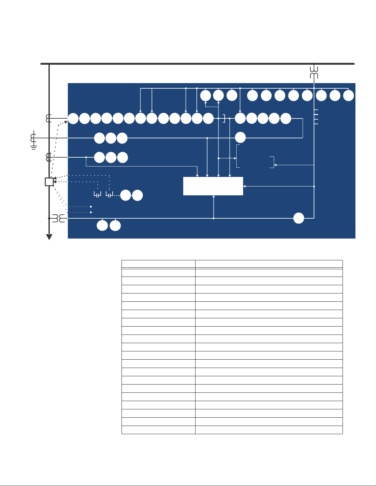
A summary of the available functions and a single-line diagram of protection and control
features is shown below. For a complete understanding of each feature operation, refer to
Chapter 4:
feature and show all logic signals passed between individual features. Information related
to the selection of settings for each setpoint is also provided.
Setpoints. The logic diagrams include a reference to every setpoint related to a
850 FEEDER PROTECTION SYSTEM – INSTRUCTION MANUAL 1–1

DESCRIPTION OF THE 850 FEEDER PROTECTION SYSTEM CHAPTER 1: INTRODUCTION
Description of the 850 Feeder Protection System
CPU
Relay functions are controlled by two processors: a Freescale MPC5125 32-bit
microprocessor that measures all analog signals and digital inputs and controls all output
relays, and a Freescale MPC8358 32-bit microprocessor that controls all the advanced
Ethernet communication protocols.
Analog Input and Waveform Capture
Magnetic transformers are used to scale-down the incoming analog signals from the
source instrument transformers. The analog signals are then passed through a 11.5 kHz
low pass analog anti-aliasing filter. All signals are then simultaneously captured by sample
and hold buffers to ensure there are no phase shifts. The signals are converted to digital
values by a 16-bit A/D converter before finally being passed on to the CPU for analysis.
The 'raw' samples are scaled in software, then placed into the waveform capture buffer,
thus emulating a fault recorder. The waveforms can be retrieved from the relay via the
EnerVista 8 Series Setup
Frequency
Frequency measurement is accomplished by measuring the time between zero crossings
of the composite signal of three-phase bus voltages, line voltage or three-phase currents.
The signals are passed through a low pass filter to prevent false zero crossings. Frequency
tracking utilizes the measured frequency to set the sampling rate for current and voltage
which results in better accuracy for the Discrete Fourier Transform (DFT) algorithm for offnominal frequencies.
The main frequency tracking source uses three-phase bus voltages. The frequency
tracking is switched automatically by an algorithm to the alternative reference source, i.e.,
three-phase currents signal or line voltage for the configuration of tie-breaker, if the
frequency detected from the three-phase voltage inputs is declared invalid. The switching
will not be performed if the frequency from the alternative reference signal is detected
invalid. Upon detecting valid frequency on the main source, the tracking will be switched
back to the main source. If a stable frequency signal is not available from all sources, then
the tracking frequency defaults to the nominal system frequency.
Phasors, Transients, and Harmonics
All waveforms are processed eight times every cycle with a DC decaying removal filter and
a Discrete Fourier Transform (DFT). The resulting phasors have fault current transients and
all harmonics removed. This results in an overcurrent relay that is extremely secure and
reliable and one that will not overreach.
Processing of AC Current Inputs
The DC Decaying Removal Filter is a short window digital filter, which removes the DC
decaying component from the asymmetrical current present at the moment a fault
occurs. This is done for all current signals used for overcurrent protection; voltage signals
use the same DC Decaying Removal Filter. This filter ensures no overreach of the
overcurrent protection.
The Discrete Fourier Transform (DFT) uses exactly one cycle of samples to calculate a
phasor quantity which represents the signal at the fundamental frequency; all harmonic
components are removed. All subsequent calculations (e.g. power, etc.) are based upon the
current and voltage phasors, such that the resulting values have no harmonic
components. RMS (root mean square) values are calculated from one cycle of samples
prior to filtering.
Protection Elements
All voltage, current and frequency protection elements are processed eight times every
cycle to determine if a pickup has occurred or a timer has expired. The voltage and current
protection elements use RMS current/voltage, or the magnitude of the phasor.
software for display and diagnostics.
1–2 850 FEEDER PROTECTION SYSTEM – INSTRUCTION MANUAL
CHAPTER 1: INTRODUCTION DESCRIPTION OF THE 850 FEEDER PROTECTION SYSTEM
892770A4.CDR
3 CTs
CT
27P
59P
59N
59_2
VTFF
81U
81O
81R
51N 50N 67N
87G
27X
59X
METERING
TRANSIENT RECORDER
EVENT RECORDER
FAULT REPORT
LOAD
BUS
TRIP52CLOSE
MONITORING
CLP50BF 51P 50P 67P 51_2 50_2 67_2 49
50G/
51G
51G
50G
67G
50G/
51G
51SG
50SG 67SG
25
32N
V_2
BUS
BREAKER
32
850 Feeder Protection System
V_0
POLE DISCORDANCE*
SOTF*
Fast Underfrequency
UV Restoration
UF Restoration
Bus Transfer
MCB
LIGHT
Broken Conductor
Load Encroachment
CT Supervision
Demand
Pulsed Outputs
Harmonic Detection
37*
21YN 27Q 27T
79
AFP
* 850-D only
55
Figure 1-1: Single Line Diagram
Table 1-1: ANSI Device Numbers and Functions
ANSI Device Description
21 YN Neutral Admittance
25 Synchrocheck
27P Phase Undervoltage
27Q UV Reactive Power
27T Timed Undervoltage Protection
27X Auxiliary Undervoltage
32 Directional Power
32N Wattmetric Ground Fault (Wattmetric zero sequence directional)
37 Undercurrent
49 Thermal Overload
50BF Breaker Failure
50G Ground Instantaneous Overcurrent
50SG Sensitive Ground Instantaneous Overcurrent
50N Neutral Instantaneous Overcurrent
50P Phase Instantaneous Overcurrent
50_2 Negative Sequence Instantaneous Overcurrent
51G Ground Time Overcurrent
51SG Sensitive Ground Time Overcurrent
51N Neutral Time Overcurrent
850 FEEDER PROTECTION SYSTEM – INSTRUCTION MANUAL 1–3
51P Phase Time Overcurrent

DESCRIPTION OF THE 850 FEEDER PROTECTION SYSTEM CHAPTER 1: INTRODUCTION
ANSI Device Description
51_2 Negative Sequence Time Overcurrent
52 AC Circuit Breaker
Pole Discordance
55 Power Factor
59N Neutral Overvoltage
59P Phase Overvoltage
59X Auxiliary Overvoltage
59_2 Negative Sequence Overvoltage
67G Ground Directional Element
67SG Sensitive Ground Directional Element
67N Neutral Directional Element
67P Phase Directional Element
67_2 Negative Sequence Directional Element
79 Automatic Recloser
81O Overfrequency
81U Underfrequency
81R Frequency Rate of Change
87G Restricted Ground Fault (RGF)
AFP Arc Flash Protection
CLP Cold Load Pickup
I1/12 Broken Conductor
MCB Manual Close Blocking
SOTF Switch Onto Fault
VTFF Voltage Transformer Fuse Failure
Table 1-2: Other Device Functions
Description
Analog Input
Analog Output
Automatic Bus Transfer Scheme (MTM)
Breaker Arcing Current (I2t)
Breaker Control
Breaker Health
CT Supervision
Current/Power Demand
Data Logger
Digital Counters
Event Recorder
Fault Report and Fault Locator
Fast Underfrequency
Flexelements
FlexLogic Equations
Flexstates
Harmonic Detection
IEC 61850 Communications
Metering: current, voltage, power, PF, energy, frequency, harmonics, THD
Load Encroachment
1–4 850 FEEDER PROTECTION SYSTEM – INSTRUCTION MANUAL

CHAPTER 1: INTRODUCTION DESCRIPTION OF THE 850 FEEDER PROTECTION SYSTEM
Description
Modbus User Map
Neutral Admittance
Non-volatile Latches
OPC-UA Communications
Output Relays
Pulsed Outputs
Setpoint Groups (6)
Trip Bus (6)
Transient Recorder (Oscillography)
Trip and Close Coil Monitoring
Underfrequency Restoration
Undervoltage Restoration
User-programmable LEDs
User-programmable Pushbuttons
Virtual Inputs (64)
Virtual Outputs (96)
850 FEEDER PROTECTION SYSTEM – INSTRUCTION MANUAL 1–5

Setpoints
Device
System
Inputs
Outputs
Protection
Monitoring
Control
FlexLogic
S
tatus
Metering
Records
Events
Transients
Data Logger
Breakers
Dig Counters
Clear Records
Targets
Fault Reports
Testing
Output Relays
Virtual Inputs
Contact Inputs
Arc Flash
Virtual Outputs
Communications
Information
Device Status
PTP Status
Clock
Last Trip Data
Flex States
Summary
Breakers
Switches
Autoreclose
Summary
Currents
Voltages
Frequency
Harmonics
Synchrocheck
Power
Energy
Current Demand
Thermal Capacity
Power Demand
Directional Power
Wattmetric Gnd Flt
Fast Underfrequency
Arc Flash
Analog Inputs
RTD Maximums
Admittance
Harmonic Detection
Power Factor
RTDs
FlexElements
Remote Modbus Device
DESCRIPTION OF THE 850 FEEDER PROTECTION SYSTEM CHAPTER 1: INTRODUCTION
Figure 1-2: Main Menu Hierarchy
1–6 850 FEEDER PROTECTION SYSTEM – INSTRUCTION MANUAL

CHAPTER 1: INTRODUCTION SECURITY OVERVIEW
Security Overview
The following security features are available:
BASIC SECURITY
The basic security feature is present in the default offering of the 850 relay. The
850 introduces the notion of roles for different levels of authority. Roles are used as login
names with associated passwords stored on the device. The following roles are available
at present: Administrator, Operator, Factory and Observer, with a fixed permission
structure for each one. Note that the Factory role is not available for users, but strictly
used in the manufacturing process.
The 850 can still use the Setpoint access switch feature, but enabling the feature can be
done only by an Administrator. Setpoint access is controlled by a keyed switch to offer
some minimal notion of security.
CYBERSENTRY
The CyberSentry Embedded Security feature is a software option that provides advanced
security services. When the software option is purchased, the Basic Security is
automatically disabled.
CyberSentry provides security through the following features:
• An Authentication, Authorization, Accounting (AAA) Remote Authentication Dial-In
User Service (RADIUS) client that is centrally managed, enables user attribution, and
uses secure standards based strong cryptography for authentication and credential
protection.
• A Role-Based Access Control (RBAC) system that provides a permission model that
device operations and configurations based on specific roles
devices using the Secure Shell (SSH) protocol, the
FASTPATH:
allows access to 850
and individual user accounts configured on the AAA server. At present the defined
roles are: Administrator, Operator and Observer.
• Strong encryption of all access and configuration network messages between the
EnerVista software and 850
Advanced Encryption Standard (AES), and 128-bit keys in Galois Counter Mode (GCM)
as specified in the U.S. National Security Agency Suite B extension for SSH and
approved by the National Institute of Standards and Technology (NIST) FIPS-140-2
standards for cryptographic systems.
• Security event reporting through the Syslog protocol for supporting Security
Information Event Management (SIEM) systems for centralized cyber security
monitoring.
There are two types of authentication supported by CyberSentry that can be used to
access the 850 device:
• Device Authentication – in which case the authentication is performed on the
device itself, using the predefined roles as users (No RADIUS involvement).
850
– 850 authentication using local roles may be done either from the front panel or
through EnerVista.
• Server Authentication - in which case the authentication is done on a RADIUS server,
using individual user accounts defined on the server. When the user accounts are
created, they are assigned to one of the predefined roles recognized by the 850
– 850 authentication using RADIUS server may be done only through EnerVista.
WiFi and USB do not currently support CyberSentry security. For this reason WiFi is
disabled by default if the CyberSentry option is purchased. The user can enable WiFi, but
be aware that doing so violates the security and compliance model that CyberSentry is
supposed to provide.
850 FEEDER PROTECTION SYSTEM – INSTRUCTION MANUAL 1–7

850 ORDER CODES CHAPTER 1: INTRODUCTION
NOTE
When both 850 device and server authentication are enabled, the 850 automatically
directs authentication requests to the 850
device or the respective RADIUS server, based
on user names. If the user ID credential does not match one of the device local accounts,
the 850
automatically forwards the request to a RADIUS server when one is provided. If a
RADIUS server is provided, but is unreachable over the network, server authentication
requests are denied. In this situation, use local 850
system.
850
device accounts to gain access to the
USER ROLES
User Access Levels are used to grant varying permissions to specific user roles. User roles
are used by both Basic Security and CyberSentry.
The following user roles are supported:
• Administrator: The Administrator role has complete read and write access to all
settings and commands. The role does not allow concurrent access. The Administrator
role also has an operand to indicate when it is logged on.
• Operator: The Operator role is present to facilitate operational actions that may be
programmed and assigned to buttons on the front panel. The Operator has read/write
access to all settings under the command menu/section. The Operator can view
settings from EnerVista or the front panel but does not have the ability to change any
settings. This role is not a concurrent role.
• Observer: The Observer role has read-only access to all 850 settings. This role allows
concurrent access. The Observer is the default role if no authentication has been done
to the device. This role can download settings files and records from the device.
• Factory: This is an internal non-user accessible role used for manufacturing
diagnostics. The ability to enable or disable this role is a security setting that the
Administrator controls.
GENERAL RULES FOR USER ROLES WITH CYBERSENTRY
1. The only concurrent role is Observer. If the user is logged in through serial, front panel,
or over the network, that counts as the role being logged in for concurrency reasons.
2. Both EnerVista and the front panel provide a one-step logoff. For the front panel, the
root menu has a logoff command. From EnerVista right-clicking on a device and
providing a logoff function from the context menu is sufficient.
3. The EnerVista Login Screen has “User Name:” and “Password:” fields for the default
remote (Radius) authentication, but when a “Local Authentication” checkbox is
selected the “User Name:” field changes to a drop down menu where the user can
select one of the predefined roles on the 850.
850 Order Codes
NOTE:
NOTE:
1–8 850 FEEDER PROTECTION SYSTEM – INSTRUCTION MANUAL
Support of some of the features described in the "Setpoints" section are order code
dependent. Each 8 Series unit is ordered with a number of required and optional modules.
Each of these modules can be supplied in a number of configurations specified at the time
of ordering.
Refer to https://www.gegridsolutions.com/multilin/catalog/850.htm for available order
code combinations.
The information to specify an 850 relay is provided in the following Order Code figure:

CHAPTER 1: INTRODUCTION 850 ORDER CODES
850 * * NN * * * * A * * * * * * * * * * * * N *
Interface 850 | | | | | | | | | | | | | | | | | | | | | |
850 Feeder Protection System (Standard: English Language,
High Voltage Power Supply, Graphical Control Panel)
Model E | | ||||||||||||||||||| Industrial
D| | ||||||||||||||||||| Distribution Feeder
Phase Currents - Slot J P1 | | | | | | | | | | | | | | | | | | | | 1A three-phase current inputs (Slot J) + 4 voltage inputs (J2)
P5 | | | | | | | | | | | | | | | | | | | | 5A three-phase current inputs (Slot J) + 4 voltage inputs (J2)
Phase Currents - Slot K NN ||||||||||||||||||| No phase current inputs (Slot K)
Ground Currents G1 | | | | | | | | | | | | | | | | | | 1A ground input
G5 | | | | | | | | | | | | | | | | | | 5A ground input
S1 | | | | | | | | | | | | | | | | | | 1A ground + 1A sensitive ground input
S5 | | | | | | | | | | | | | | | | | | 5A ground + 5A sensitive ground input
D1 | | | | | | | | | | | | | | | | | | 1A ground + 1A polarizing current input
D5 | | | | | | | | | | | | | | | | | | 5A ground + 5A polarizing current input
Power Supply L | | ||||||||||||||| 24 to 48 V DC
H||||||||||||||||| 110 to 250 V DC/110 to 230 V AC
Slot B (LV I/O) N | | | | | | | | | | | | | | | | None
R | | | | | | | | | | | | | | | | 6 x RTDs (Pt100, Ni100, Ni120)
S | | | | | | | | | | | | | | | | 6 x RTDs (Pt100, Ni100, Ni120, Cu10)
Slot C (LV I/O) N ||||||||||||||| None
R||||||||||||||| 6 x RTDs (Pt100, Ni100, Ni120)
S||||||||||||||| 6 x RTDs (Pt100, Ni100, Ni120, Cu10)
Slot F (HV I/O) A
||||||||||||||||||||||||||||2 Form A (Vmon), 3 Form C, 7 Digital Inputs (Low/High
Voltage, Int/Ext Supply)
Slot G (HV I/O) N ||||||||||||| None
A
||||||||||||||||||||||||||2 Form A (Vmon), 3 Form C, 7 Digital Inputs (Low/High
Voltage, Int/Ext Supply)
L||||||||||||| 7 DcmA O/P + 4 DcmA I/P + 1 RTD
Slot H (HV I/O) N | | | | | | | | | | | | None
A
||||||||||||||||||||||||2 Form A (Vmon), 3 Form C, 7 Digital Inputs (Low/High
Voltage, Int/Ext supply)
F | | | | | | | | | | | | 10 Digital Inputs + 4 Arc Flash Inputs
Faceplate M | | | |||||||| Basic = Membrane Keypad
G||||||||||| Standard = Rugged Keypad
Current Protection S | | | | | | | | | | Basic (850-E): 50P(2), 50N(2), 50G(1), 51P(2), 51N(2), 51G(1)
M | | | | | | | | | |
Standard (850-E): Basic + 50SG(1), 50_2(1), 51SG(1), 51_2(1),
RGF(1)
D
|
|
|
|
|
|
|
|
|
|
|
|
|
|
|
|
|
|
|
|
|
|
|
|
|
|
|
|
|
|
|
|
|
|
|
|
|
|
|
|
|
|
|
|
|
|
|
|
|
|
|
|
|
|
|
|
|
|
|
|
Standard (850-D) = 37(3), 50P (4/CT bank), 50N (4/CT bank),
50G (4/CT bank), 51P(4), 51N(4), 51G(2/CT bank), 50SG(4/CT
bank), 50_2(4/CT bank), 51SG(2/CT bank), 51_2 (2/CT bank),
RGF(3), SOTF (3/Bkr), 67P(4), 67N(4), 67G (1/CT bank), 67SG (1/
CT bank), 67_2 (1/CT bank), 49(2), Load Encroachment (1/CT
bank), Broken Conductor (3)
A
|||||||||||||||||||
|
Advanced (850-E): Standard (850-E) + 67P(1), 67N(1), 67G(1),
67SG(1), 67_2(1), 49(2), Load Encroachment 1), Broken
Conductor(1)
Voltage Monitoring and Protection S||
|
|
|
|
|
|
|
|
|
|
|
|
|
|
|
|
|
|
|
|
|
|
|
|
|
Standard Voltage Metering & Protection: 27P (4/VT bank),
27X (2/VT bank), 59P(4), 59N(4), 59X (2/VT bank, 81O (6/VT
bank), 81U (6/VT bank)
P||
|
|
|
|
|
|
|
|
|
|
|
|
|
|
|
|
|
|
|
|
|
|
|
|
|
Advanced Voltage Metering & Protection: Standard + 25 (1/
CT bank), 27T(4), 27Q(3/Bkr), 32(4), 32N(4), 55(4), 59_2 (2/VT
banks), 81R (6/VT bank), Fast U/F (8), Neutral Admittance (3)
Control B
||||||||||||||||Basic (850-E): Setpoint Group Control, Virtual Inputs, Trip
Bus, Breaker Control, VTFF
F
||||||||||||||||Standard (850-E): Basic + FlexLogic, CLP, 50BF (2/CT bank),
CT Supervision(3)
D
|
|
|
|
|
|
|
|
|
|
|
|
|
|
|
|
|
|
|
|
|
|
|
|
|
|
|
|
|
|
|
|
Standard (850-D): Setpoint Group Control, Virtual Inputs,
Trip Bus(6), Breaker Control (1/Bkr), VTFF (1/VT bank),
FlexLogic, CLP (1/Bkr), 50BF (2/CT bank), Pole
Discordance(3), Autoreclose (1/Bkr), CT Supervision(3)
C
||||||||||||||||Advanced (850-E): Standard + Autoreclose, Bus Transfer
(requires voltage option P)
H
||||||||||||||||Advanced HMI (850-E): Advanced + Tab PBs, Annunciator
Panel, Configurable SLDs with Bay Control
T||||||||||||||||
Advanced (850-D): Standard + Tab PBs, Annunciator Panel,
Configurable SLDs with Bay Control
Monitoring B||
|
|
|
|
|
|
|
|
|
|
|
|
|
|
|
|
|
|
|
Basic: Breakers Coil Monitoring (1/Bkr), Breaker Arcing (1/
Bkr), THD, Current Demand (1/CT bank), Digital Counters
(16), Data Logger
C||||||| Standard: Basic + Advanced Breaker Health (1/Bkr)
A||||||| Advanced: Standard + Harmonic Detection(6)
Figure 1-3: 850 Order Codes
850 FEEDER PROTECTION SYSTEM – INSTRUCTION MANUAL 1–9

850 ORDER CODES CHAPTER 1: INTRODUCTION
892800A5.PDF
Communications S E
||||||||||Standard: Front USB, 1 x Rear RS485: Modbus RTU, DNP3.0,
IEC60870-5-103 + 1 x Ethernet (Modbus TCP, DNP)
1 E
|
|
|
|
|
|
|
|
|
|
|
|
|
|
|
Advanced: Front USB, 1 x Rear RS485 + 2 x Ethernet Fiber,
MODBUS RTU/TCP, DNP3.0, IEC 60870-5-103/104, 1588,
SNTP, OPC-UA
1 P | | | | | Advanced + PRP
2 A
|||||||||
|
Advanced + IEC 61850
2 E | | | | | Advanced + PRP + IEC 61850
3 A
|||||||||
|
Advanced + Extended IEC 61850
3 E | | | | | Advanced + PRP + Extended IEC 61850
Advanced Communications Connector N |||| None
S|||| ST, Multi-mode 1310 nm
C|||| RJ45, Copper 10/100 M
Wireless Communication N | | | None
W | | | WiFi 802.11
Security B| | Basic
A| | Advanced: CyberSentry Level 1
Future Option N | Not Available
Retrofit Kit Option 1
Wye 750-850 Retrofit Kit, terminal block wiring assembly
for wye (for retrofit kit only)
2
Delta 750-850 Retrofit Kit, terminal block wiring assembly
for delta (for retrofit kit only)
3
Wye 735-850 Retrofit Kit, terminal block wiring assembly
for wye (for retrofit kit only)
4
Delta 735-850 Retrofit Kit, terminal block wiring assembly
for delta (for retrofit kit only)
850 * * NN * * * * A * * * * * * * * * * * * N *
FASTPATH:
Harsh Environment Coating is a standard feature on all 8 Series units.
Advanced security is only available with advanced communications (1E, 1P, 2A, 2E, 3A, 3E).
When the advanced communications option is selected, the Ethernet port on the main CPU
is disabled.
FASTPATH:
Retrofit order codes must be configured using the GE Multilin Online Store (OLS) based on
the existing relay order code and additional requirements.
Navigate to https://www.gegridsolutions.com/multilin/catalog/850.htm
Retrofit Kit for further information.
Accessories
• 18J0-0030 8 Series Depth Reducing Collar - 1 3/8"
• 18J0-0029 8 Series Depth Reducing Collar - 3"
1–10 850 FEEDER PROTECTION SYSTEM – INSTRUCTION MANUAL
• 8 Series Retrofit Kit , 750/760 to 850
• 8 Series Retrofit Kit, 735 to 850
and click Buy

CHAPTER 1: INTRODUCTION SPECIFICATIONS
Specifications
To obtain the total operating time, i.e. from the presence of a trip condition to initiation of a
trip, add 8 ms output relay time to the operate times listed below.
Device
ANNUNCIATOR PANEL
Number of Elements: ........................................1 (36 indicators)
Layout:.....................................................................Grid of 2x2 or 3x3
Data Storage:........................................................Non-volatile memory
Mode:........................................................................Self-reset, latched, acknowledgeable
Display Text:..........................................................3 lines of 15 characters maximum
Visual Indication:.................................................Flashing: 2Hz @ 50% duty cycle
CUSTOM CONFIGURATIONS
Config Mode:.........................................................Simplified, Regular
Protection
ARC FLASH HS PHASE/GROUND INSTANTANEOUS OVERCURRENT HS 50P/50G
Current:....................................................................Phasor Magnitude (special high speed algorithm)
Pickup Level:..........................................................0.050 to 30.000 x CT in steps of 0.001 x CT
Dropout Level: ......................................................97 to 98% of Pickup
Level Accuracy:....................................................For 0.1 to 0.2 x CT: ± 0.2% of reading or 1.5% of rated,
whichever is greater
For > 0.2 x CT: ± 1.5% of reading
Operate Time:.......................................................4 ms at >6 x Pickup at 60 Hz
5 ms at >6 x Pickup at 50 Hz
4-8 ms at > (3-6) x Pickup at 60 Hz
4-10 ms at > (3-6) x Pickup at 50 Hz
AUXILIARY OVERVOLTAGE (59X)
Operating Parameter:.......................................Vx (Phasor)
Pickup Level:..........................................................0.00 to 3.00 x VT in steps of 0.01 x VT
Dropout Level: ......................................................97 to 98% of Pickup
Level Accuracy:....................................................±0.5% of reading from 10 to 240 V
Overvoltage Curves: ..........................................Definite Time, Inverse T ime, FlexCurves A/B/C/D
Pickup Time Delay:.............................................0.000 to 6000.000 s in steps of 0.001s
Dropout Time Delay: .........................................0.000 to 6000.000 s in steps of 0.001s
Pickup Accuracy:.................................................‘Auxiliary voltage input channel error
Operate Time:.......................................................< 30 ms at 1.1 x pickup at 60Hz
Curve Timing Accuracy: ..................................at >1.1 x PKP: 3.5% of operate time ± ½ cycle (whichever is
greater) from pickup to operate
Timer Accuracy: ..................................................± 3% of operate time or ± ½ cycle (whichever is greater)
850 FEEDER PROTECTION SYSTEM – INSTRUCTION MANUAL 1–11

SPECIFICATIONS CHAPTER 1: INTRODUCTION
AUXILIARY UNDERVOLTAGE (27X)
Operating Parameter: ......................................Vx (Phasor)
Minimum Voltage: .............................................. 0.00 to 1.50 x VT in steps of 0.01 x VT
Pickup Level: .........................................................0.00 to 1.50 x VT in steps of 0.01 x VT
Dropout Level:......................................................102 to 103% of Pickup
Level Accuracy: ...................................................± 0.5% of reading from 10 to 208 V
Undervoltage Curves:.......................................Definite Time, GE IAV Inverse Time or FlexCurves A/B/C/D
Pickup Time Delay: ............................................0.000 to 6000.000 s in steps of 0.001 s
Operate Time: ......................................................< 20 ms at 0.90 x pickup at 60 Hz
< 25 ms at 0.90 x pickup at 50 Hz
Curve Timing Accuracy:.................................. at < 0.90 x pickup: ± 3.5% of curve delay or ± ½ cycle
(whichever is greater) from pickup to operate
BROKEN CONDUCTOR
Minimum Operating Positive Current:.......0.05 to 1.00 x CT in steps of 0.01 x CT
Maximum Operating Positive Current: .....0.05 to 5.00 x CT in steps of 0.01 x CT
Pickup Level: .........................................................20.0% to 100.0% in steps of 0.1%
Dropout Level:......................................................97% to 98% of the Pickup Level
Pickup Time Delay: ............................................0.000 to 6000.000 s in steps of 0.001 s
Timer Accuracy:..................................................± 3% of delay setting or ± ¾ cycle (whichever is greater)
from pickup to operate
DIRECTIONAL POWER (32)
Measured Power:................................................3-phase
Number of Stages: ............................................. 2
Characteristic Angle:......................................... 0º to 359º in steps of 1°
Calibration Angle: ............................................... 0.00º to 0.95º in steps of 0.05°
Power Pickup Range: ........................................ –1.200 to 1.200 x Rated Power in steps of 0.001
Pickup Level Accuracy:.................................... ± 1% or ± 0.001 x Rated Power, whichever is greater
Hysteresis: .............................................................2% or 0.001 x Rated Power, whichever is greater
Pickup Time Delay: ............................................0.000 to 6000.000 s in steps of 0.001 s
Operate Time: ......................................................< 55 ms at 1.1 x pickup at 60 Hz
< 65 ms at 1.1 x pickup at 50 Hz
Timer Accuracy:..................................................± 3% of delay setting or ± ¼ cycle (whichever is greater)
from pickup to operate
FAST UNDERFREQUENCY
Operating Parameter: ......................................Frequency and rate of change of frequency
UF Pickup Level:................................................... 20.00 to 65.00 Hz in steps of 0.01 Hz
df/dt Pickup Level:..............................................-10.00 to -0.10 Hz/s in steps of 0.01 Hz/s
Pickup Time Delay: ............................................0.000 to 6000.000 s in steps of 0.001 s
Dropout Time Delay:......................................... 0.000 to 6000.000 s in steps of 0.001 s
Frequency Accuracy:........................................± 0.01 Hz
Timer Accuracy:..................................................± 3% of operate time or ± ¼ cycle (whichever is greater)
FLEXELEMENTS
Number of elements:........................................ 8
Operating signal: ................................................Any analog actual value, or two values in a differential mode
Operating signal mode:................................... Signed, or Absolute value
Operating mode:.................................................Level, Delta
Comparison direction:......................................Over, Under
Pickup Level: .........................................................-30.000 to 30.000 pu in steps of 0.001 pu
Hysteresis: .............................................................0.1 to 50.0% in steps of 0.1%
Delta dt:...................................................................40 msec to 45 days
Pickup and dropout delays:........................... 0.000 to 6000.000 s in steps of 0.001 s
1–12 850 FEEDER PROTECTION SYSTEM – INSTRUCTION MANUAL

CHAPTER 1: INTRODUCTION SPECIFICATIONS
FREQUENCY RATE OF CHANGE (81R)
df/dt Trend:............................................................Increasing, Decreasing, Bi-directional
df/dt Pickup Level: ..............................................0.10 to 15.00 Hz/s in steps of 0.01 Hz/s
df/dt Dropout Level:...........................................96% of Pickup Level
df/dt Level Accuracy:........................................80 mHz/s or 3.5%, whichever is greater
Minimum Frequency:........................................20.00 to 80.00 Hz in steps of 0.01 Hz
Maximum Frequency:.......................................20.00 to 80.00 Hz in steps of 0.01 Hz
Minimum Voltage Threshold:.........................0.000 to 1.250 x VT in steps of 0.001 x VT
Minimum Current Threshold:.........................0.000 to 30.000 x CT in steps of 0.001 x CT
Pickup Time Delay:.............................................0.000 to 6000.000 s in steps of 0.001 s
Timer Accuracy: ..................................................± 3% of delay setting or ± ¼ cycle (whichever is greater)
from pickup to operate
95% Settling Time for df/dt:...........................< 24 cycles
Operate Time:.......................................................typically 10 cycles at 2 × Pickup
GROUND DIRECTIONAL OVERCURRENT (67G)
Directionality: .......................................................Co-existing forward and reverse
Polarizing: ...............................................................Voltage, Current, Dual
Polarizing Voltage:..............................................V_0 or VX
Polarizing Current:..............................................Isg
Operating Current: .............................................Ig
Level Sensing:.......................................................Ig, Isg
Characteristic Angle:.........................................-90º to 90º in steps of 1°
Limit Angle: ............................................................40º to 90º in steps of 1°, independent for forward and
reverse
Angle Accuracy: ..................................................±2º
Pickup Level:..........................................................0.050 to 30.000 x CT in steps of 0.001
Dropout Level: ......................................................97 to 98%
Operate Time (no direction transition):.....< 12 ms typical at 3 x Pickup at 60 Hz
< 15 ms typical at 3 x Pickup at 50 Hz
LOAD ENCROACHMENT
Operating Parameter:.......................................Positive sequence impedance (V1/I1)
Reach (in secondary Ω):...................................0.02 to 250.00 Ω in steps of 0.01Ω
Angle:........................................................................5º to 50º in steps of 1°
Minimum Voltage:...............................................0.00 to 1.50 x VT in steps of 0.01 x VT
Impedance Accuracy: ......................................± 5%
Angle Accuracy: ..................................................± 2º
Pickup Time Delay:.............................................0.000 to 6000.000 s in steps of 0.001 s
Dropout Time Delay: .........................................0.000 to 6000.000 s in steps of 0.001 s
Operate Time:.......................................................<20 ms at 1.1 x pickup at 60 Hz
<24 ms at 1.1 x pickup at 50 Hz
Timing Accuracy:................................................± 3% of delay setting or ± ¼ cycle (whichever is greater)
from pickup to operate
850 FEEDER PROTECTION SYSTEM – INSTRUCTION MANUAL 1–13

SPECIFICATIONS CHAPTER 1: INTRODUCTION
NOTE
NEGATIVE SEQUENCE TIME OVERCURRENT (51_2)
Operating Parameter: ......................................I_2 (Fundamental Phasor Magnitude)
Pickup Level: .........................................................0.050 to 30.000 x CT in steps of 0.001 x CT
Dropout Level:......................................................97 to 98% of Pickup
Level Accuracy: ...................................................For 0.1 to 2.0 x CT:± 0.5% of reading or ±0.4% of rated,
whichever is greater
For > 2.0 x CT: ± 1.5% of reading
Curve Shape:......................................................... IEEE Extremely/Very/Moderately Inverse
ANSI Extremely/Very/Normally/Moderately Inverse
IEC Curve A/B/C and Short Inverse
IAC Extreme/Very/Inverse/Short Inverse
FlexCurve™ A, FlexCurve™ B, FlexCurve™ C, FlexCurve™ D
2
I
t, I4t, Definite Time
Curve Multiplier: ..................................................0.05 to 600.00 in steps of 0.01
Reset Time: ............................................................Instantaneous, Timed
Curve Timing Accuracy:.................................. Currents > 1.1 x pickup: ± 3% of curve delay or ± ½ cycle
(whichever is greater) from pickup to operate
NOTE:
Add 1.5 cycles to the curve time to obtain the TOC operating time, i.e., from fault inception
until operation.
NEGATIVE SEQUENCE INSTANTANEOUS OVERCURRENT (50_2)
Current:.................................................................... I_2 Fundamental Phasor Magnitude
Pickup Level: .........................................................0.050 to 30.000 x CT in steps of 0.001 x CT
Dropout Level:......................................................97 to 98% of Pickup
Level Accuracy: ...................................................For 0.1 to 2.0 x CT: ±0.5% of reading or ± 0.4% of rated,
whichever is greater
For > 2.0 x CT: ± 1.5% of reading
Pickup Time Delay: ............................................0.000 to 6000.000 s in steps of 0.001 s
Dropout Time Delay:......................................... 0.000 to 6000.000 s in steps of 0.001 s
Overreach: .............................................................< 2%
Operate Time: ......................................................< 12 ms typical at 3 x Pickup at 60 Hz
< 15 ms typical at 3 x Pickup at 50 Hz
Timer Accuracy:.................................................. ±3% of delay setting or ± ¼ cycle (whichever is greater) from
pickup to operate
NEUTRAL ADMITTANCE (21YN)
Operating Characteristic (Modes):.............. Admittance, Conductance and Susceptance
Directionality: ....................................................... Non-directional, Forward and Reverse
Reach Admittance
(secondary Siemens): ................................. 0.00 to 500.00 mS in steps of 0.01
Reach Conductance\ Susceptance
(secondary Siemens): ................................. -500.00 to 500.00 mS in steps of 0.01
Level Accuracy: ...................................................±1% of Pickup or ±0.01 mS, whichever is greater
Pickup Delay:........................................................ 0.000 to 600.000 s in steps of 0.001
Dropout Level:......................................................0.000 to 600.000 s in steps of 0.001
Time Accuracy:.................................................... ±3% of delay setting time or ±20 ms, whichever is greater
Pickup:...................................................................... < 12 ms typical at 3 x Pickup at 60 Hz
Minimum Current Supervision
Pickup: ................................................................ 0.02 to 1.00 x CT in steps of 0.01
Dropout:.................................................................. 103% of pickup
Minimum Voltage Supervision
Pickup: ................................................................ 0.01 to 1.50 x VT in steps of 0.01
Dropout:.................................................................. 103% of pickup
1–14 850 FEEDER PROTECTION SYSTEM – INSTRUCTION MANUAL

CHAPTER 1: INTRODUCTION SPECIFICATIONS
NEUTRAL DIRECTIONAL OVERCURRENT (67N)
Directionality: .......................................................Co-existing forward and reverse
Polarizing: ...............................................................Voltage, Current, Dual
Polarizing Voltage:..............................................V_0 or VX
Polarizing Current:..............................................Ig
Operating Current: .............................................I_0
Level Sensing:.......................................................3 x (|I_0| – K x |I_1|), Ig
Restraint, K: ...........................................................0.000 to 0.500 in steps of 0.001
Characteristic Angle:.........................................-90º to 90º in steps of 1°
Limit Angle: ............................................................40º to 90º in steps of 1°, independent for forward and
reverse
Angle Accuracy: ..................................................±2º
Pickup Level:..........................................................0.050 to 30.000 x CT in steps of 0.001 x CT
Dropout Level: ......................................................97 to 98% of Pickup
Operate Time (no direction transition):.....< 16 ms at 3 x Pickup at 60 Hz
< 20 ms at 3 x Pickup at 50 Hz
NEGATIVE SEQUENCE DIRECTIONAL OVERCURRENT (67_2)
Directionality: .......................................................Co-existing forward and reverse
Polarizing: ...............................................................Voltage
Polarizing Voltage:..............................................V_2
Operating Current: .............................................I_2
Level Sensing:.......................................................Negative-sequence: |I_2| – K x |I_1|
Restraint, K: ...........................................................0.000 to 0.500 in steps of 0.001
Characteristic Angle:.........................................0º to 90º in steps of 1°
Limit Angle: ............................................................40º to 90º in steps of 1°, independent for forward and
reverse
Angle Accuracy: ..................................................± 2º
Pickup Level:..........................................................0.050 to 30.000 x CT in steps of 0.001 x CT
Dropout Level: ......................................................97 to 98% of Pickup
Operate Time:.......................................................< 12 ms typical at 3 x Pickup at 60 Hz
< 15 ms typical at 3 x Pickup at 50 Hz
NEUTRAL OVERVOLTAGE (59N)
Operating Parameter:.......................................3V_0 calculated from phase to ground voltages
Pickup Level:..........................................................0.02 to 3.00 x VT in steps of 0.01 x VT
Dropout Level: ......................................................97 to 98% of Pickup
Level Accuracy:....................................................±0.5% of reading from 10 to 208 V
Neutral Overvoltage Curves: .........................Definite time, FlexCurve A,B,C,D
Pickup Time Delay:.............................................0.000 to 6000.000 s in steps of 0.001 s (Definite Time)
Dropout Time Delay: .........................................0.000 to 6000.000 s in steps of 0.001 s (Def inite T ime)
Operate Time:.......................................................< 25 ms at 1.1 x pickup at 60Hz
< 30 ms at 1.1 x pickup at 50Hz
Curve Timing Accuracy: ..................................at > 1.1 x Pickup: ± 3% of curve delay or ± 1 cycle (whichever
is greater) from pickup to operate
NEGATIVE SEQUENCE OVERVOLTAGE (59_2)
Operating Parameter:.......................................V_2
Pickup Level:..........................................................0.00 to 3.00 x VT in steps of 0.01 x VT
Dropout Level: ......................................................97 to 98% of Pickup
Level Accuracy:....................................................± 0.5% of reading from 10 to 208 V
Pickup Time Delay:.............................................0.000 to 6000.000 s in steps of 0.001 s
Dropout Time Delay: .........................................0.000 to 6000.000 s in steps of 0.001 s
Operate Time:.......................................................< 25 ms at 1.1 x pickup at 60 Hz
< 30 ms at 1.1 x pickup at 50 Hz
Timer Accuracy: .................................................. ± 3% of delay setting or ± ¼ cycle (whichever is greater)
from pickup to operate
850 FEEDER PROTECTION SYSTEM – INSTRUCTION MANUAL 1–15

SPECIFICATIONS CHAPTER 1: INTRODUCTION
OVERFREQUENCY (81O)
Pickup Level: .........................................................20.00 to 65.00 Hz in steps of 0.01
Dropout Level:......................................................Pickup - 0.03 Hz
Pickup Time Delay: ............................................0.000 to 6000.000 s in steps of 0.001 s
Dropout Time Delay:......................................... 0.000 to 6000.000 s in steps of 0.001 s
Minimum Operating Voltage:........................ 0.000 to 1.250 x VT in steps of 0.001 x VT
Level Accuracy: ...................................................± 0.001 Hz
Timer Accuracy:..................................................± 3% of delay setting or ± ¼ cycle (whichever is greater)
from pickup to operate
Operate Time: ......................................................typically 7.5 cycles at 0.1 Hz/s change
typically 7 cycles at 0.3 Hz/s change
typically 6.5 cycles at 0.5 Hz/s change
FASTPATH:
Typical times are average Operate Times including variables such as frequency change
instance, test method, etc., and may vary by ± 0.5 cycles.
PHASE/NEUTRAL/GROUND TIME OVERCURRENT (51P/N/G)
Current:.................................................................... Phasor or RMS
Pickup Level: .........................................................0.050 to 30.000 x CT in steps of 0.001 x CT
Dropout Level:......................................................97 to 98% of Pickup
Level Accuracy: ...................................................For 0.1 to 2.0 x CT: ±0.5% of reading or ±0.4% of rated,
whichever is greater;
For > 2.0 x CT: ±1.5% of reading
Curve Shape:......................................................... IEEE Extremely/Very/Moderately Inverse;
ANSI Extremely/Very/Normally/Moderately Inverse;
Definite T ime, IEC A/B/C and Short Inverse;
IAC Extremely/Very/Inverse/Short Inverse;
FlexCurve A/B/C/D, I
2
t, I4t
Curve Multiplier: ..................................................0.05 to 600.00 in steps of 0.01
Reset Time: ............................................................Instantaneous, Timed
Curve Timing Accuracy:.................................. Currents > 1.03 to 20 x pickup: ± 3% of operate time or ± ½
cycle (whichever is greater) from pickup to operate
Voltage Restrained Function (51V): ............ Modifies Pickup from 0.1 < V < 0.9 VT Nominal in a fixed
linear relationship
FASTPATH:
Add 1.5 cycles to the curve time to obtain the TOC operating time, i.e., from fault inception
until operation.
PHASE/NEUTRAL/GROUND INSTANTANEOUS OVERCURRENT (50P/N/G)
Current (for Phase IOC only):......................... Phasor or RMS
Current (for Neutral/Ground IOC only):.....Fundamental Phasor Magnitude
Pickup Level: .........................................................0.050 to 30.000 x CT in steps of 0.001 x CT
Dropout Level:......................................................97 to 98% of Pickup
Level Accuracy: ...................................................For 0.1 to 2.0 x CT: ±0.5% of reading or ±0.4% of rated,
whichever is greater
For > 2.0 x CT: ±1.5% of reading
Operate Time: ......................................................<12 ms typical at 3 × Pickup at 60 Hz (Phase/Ground IOC)
<16 ms typical at 3 × Pickup at 60 Hz (Neutral IOC)
<15 ms typical at 3 × Pickup at 50 Hz (Phase/Ground IOC)
<20 ms typical at 3 × Pickup at 50 Hz (Neutral IOC)
NOTE:
Operating time specifications given above are applicable when RMS inputs are used.
Typical times are average operate times over multiple test cases.
Timer Accuracy:.................................................. ±3% of delay setting or ± ¼ cycle (whichever is greater) from
pickup to operate
1–16 850 FEEDER PROTECTION SYSTEM – INSTRUCTION MANUAL

CHAPTER 1: INTRODUCTION SPECIFICATIONS
PHASE DIRECTIONAL OVERCURRENT (67P)
Relay Connection: ..............................................90º(Quadrature)
Quadrature Voltage:..........................................ABC phase seq.: phase A (Vbc), phase B (Vca), phase C (Vab);
ACB phase seq.: phase A (Vcb), phase B (Vac), phase C (Vba)
Polarizing Voltage Threshold:........................0.050 to 3.000 x VT in steps of 0.001 x VT
Current Sensitivity Threshold:.......................0.05 x CT
Characteristic Angle:.........................................0º to 359º in steps of 1°
Angle Accuracy: ..................................................± 2º
Operation Time (FlexLogic™ operands): ..Reverse to Forward transition: < 12 ms, typically;
Forward to Reverse transition: <8 ms, typically
PHASE UNDERVOLTAGE (27P)
Voltage:....................................................................Fundamental Phasor Magnitude
Minimum Voltage:...............................................0.00 to 1.50 x VT in steps of 0.01 x VT
Pickup Level:..........................................................0.00 to 1.50 x VT in steps of 0.01 x VT
Dropout Level: ......................................................102 to 103% of Pickup
Level Accuracy:....................................................±0.5% of reading from 10 to 208 V
Phases Required for Operation:...................Any one, Any two, All three
Undervoltage Curves: .......................................Definite Time, GE IAV Inverse Time or FlexCurves A/B/C/D
Pickup Time Delay:.............................................0.000 to 6000.000 s in steps of 0.001s
Operate Time:.......................................................< 20 ms at 0.90 x pickup at 60 Hz
< 25 ms at 0.90 x pickup at 50 Hz
Curve Timing Accuracy: ..................................at < 0.90 x pickup: ± 3.5% of curve delay or ± ½ cycle
(whichever is greater) from pickup to operate
PHASE OVERVOLTAGE (59P)
Voltage:....................................................................Fundamental Phasor Magnitude
Pickup Level:..........................................................0.02 to 3.00 x VT in steps of 0.01 x VT
Dropout Level: ......................................................97 to 98% of Pickup
Level Accuracy:....................................................±0.5% of reading from 10 to 208 V
Phases Required for Operation:...................Any one, Any two, All three
Pickup Time Delay:.............................................0.000 to 6000.000 s in steps of 0.001s (Definite T ime)
Dropout Time Delay: .........................................0.000 to 6000.000 s in steps of 0.001s (Definite Time)
Pickup Accuracy:.................................................Per phase voltage input channel error
Operate Time:.......................................................< 25 ms at 1.1 x pickup at 60Hz
< 30 ms at 1.1 x pickup at 50Hz
Timer Accuracy: ..................................................± 3% of delay setting or ± ¼ cycle (whichever is greater)
from pickup to operate
RESTRICTED GROUND (EARTH) FAULT (87G)
Operating Parameter:.......................................Ia, Ib, Ic and Ig (Fundamental Phasor Magnitude)
Pickup Level:..........................................................0.050 to 30.000 x CT in steps of 0.001 x CT (phase CT)
Ground Supervision Level:..............................0.050 to 30.000 x CT in steps of 0.001 x CT (ground CT)
Dropout Level: ......................................................97 to 98% of Pickup
Slope Range: .........................................................0 to 100% in steps of 1%
Pickup Delay: ........................................................0.000 to 6000.000 s in steps of 0.001 s
Level Accuracy:....................................................For 0.1 to 2.0 x CT: ±0.5% of reading or ±0.4% of rated,
whichever is greater
For > 2.0 x CT: ± 1.5% of reading
Operate Time:.......................................................<25 ms at 1.1 x slope x Imax at 60 Hz, typically
<30 ms at 1.1 x slope x Imax at 50 Hz, typically
Timing Accuracy:................................................±3% of delay setting or ± ¼ cycle (whichever is greater) from
pickup to operate
RTD PROTECTION
Pickup:......................................................................1°C to 250°C in steps of 1°C
Hysteresis:..............................................................2°C
Timer Accuracy: ..................................................<2 s
Elements: ................................................................Trip and Alarm
850 FEEDER PROTECTION SYSTEM – INSTRUCTION MANUAL 1–17

SPECIFICATIONS CHAPTER 1: INTRODUCTION
SENSITIVE GROUND TIME OVERCURRENT (51SG)
Operating Parameter: ......................................Isg (RMS or Fundamental)
Pickup Level: .........................................................0.005 to 3.000 xCT in steps of 0.001 xCT
Pickup Level: .........................................................0.005 to 3.000 xCT in steps of 0.001 xCT
0.50 to 15.00 A in steps of 0.01 A (For 50:0.025)
Dropout Level:......................................................97 to 98% of Pickup
Level Accuracy: ...................................................For 0.1 to 2.0 xCT: ±0.5% of reading or ±0.4%of rated
(whichever is greater)
For > 2.0 xCT: ±1.5% of reading > 2.0 xCT rating
Level Accuracy: ...................................................For 0.1 to 2.0 xCT: ±0.5% of reading or ±0.4%of rated
(whichever is greater)
For > 2.0 xCT: ±1.5% of reading > 2.0 xCT rating
For 50:0.025: ±0.1A for 0.5A to 4A; ±0.2A for >4A
Dropout Level:......................................................97 to 98% of Pickup
Curve Shape:......................................................... IEEE Extremely/Very/Moderately Inverse
ANSI Extremely/Very/Normally/Moderately Inverse
IEC A/B/C and Short Inverse
IAC Extreme/Very/Inverse/Short Inverse
I2t, I4t, FlexCurve A/B/C/D, Definite T ime
Curve Multiplier: ..................................................0.05 to 600.00 in steps of 0.01
Reset Time: ............................................................Instantaneous, Timed
Curve Timing Accuracy:.................................. Currents > 1.03 to 20 x pickup: ± 3% of operate time or
± ½ cycle (whichever is greater) from pickup to operate
SENSITIVE GROUND INSTANTANEOUS OVERCURRENT (50SG)
Operating Parameter: ......................................Isg (Fundamental Phasor Magnitude)
Pickup Level: .........................................................0.005 to 3.000 xCT in steps of 0.001 xCT
Pickup Level: .........................................................0.005 to 3.000 xCT in steps of 0.001 xCT
Dropout Level:......................................................97 to 98% of Pickup
Level Accuracy: ...................................................For 0.1 to 2.0 xCT: ±0.5% of reading or ±0.4% of rated
(whichever is greater)
For > 2.0 xCT: ±1.5% of reading > 2.0 xCT rating
Level Accuracy: ...................................................For 0.1 to 2.0 xCT: ±0.5% of reading or ±0.4% of rated
(whichever is greater)
For > 2.0 xCT: ±1.5% of reading > 2.0 xCT rating
Operate Time: ......................................................< 12 ms at 3 × Pickup at 60 Hz
Timer Accuracy:..................................................±3% of operate time or ± ¼ cycle (whichever is greater)
1–18 850 FEEDER PROTECTION SYSTEM – INSTRUCTION MANUAL

CHAPTER 1: INTRODUCTION SPECIFICATIONS
SENSITIVE GROUND DIRECTIONAL OVERCURRENT (67SG)
Directionality: .......................................................Co-existing forward and reverse
Polarizing: ...............................................................Voltage, Current, Dual
Polarizing Voltage:..............................................V_0 or VX
Polarizing Current:..............................................Ig
Operating Current: .............................................Isg
Level Sensing:.......................................................Ig, Isg
Characteristic Angle:.........................................-90º to 90º in steps of 1°
Limit Angle: ............................................................40º to 90º in steps of 1°, independent for forward and
reverse
Angle Accuracy: ..................................................± 2º
Pickup Level:..........................................................0.005 to 3.000 x CT in steps of 0.001 x CT
Dropout Level: ......................................................97 to 98%
Operate Time (no direction transition):.....< 12 ms typical at 3 × Pickup at 60 Hz
< 15 ms typical at 3 × Pickup at 50 Hz
SOTF (SWITCH ON TO FAULT)
Number of Elements: ........................................6 (3 per Breaker)
Pickup Threshold:................................................0.050 to 10.000 pu of CT in steps of 0.001
Pickup Level Accuracy: ....................................0.1 to 2.0 x CT rating: ±0.5% of reading or ±1% of rated
(whichever is greater)
> 2.0 x CT rating: ±1.5% of reading
Pickup Level:..........................................................0.05 to 1.00 x VT in steps of 0.01
Level Accuracy:....................................................±0.5% of reading from 10 to 240 V
Pickup Delay: ........................................................0.000 to 600.000 s in steps of 0.01
Time Accuracy:....................................................±3% or ±35 ms, whichever is greater
Operate Time:.......................................................<10 ms @ 60Hz
TIMED UNDERVOLTAGE - TIMED UV (27T)
Operating Parameter:.......................................[VA, VB, VC] or [VA, VB, VC] (Phasor)
Minimum Voltage:...............................................0.00 to 1.50 (VT) in steps of 0.01 VT
Pickup Level:..........................................................0.00 to 1.50 (VT) in steps of 0.01 VT
Dropout Level: ......................................................102.0% to 150.0% of PKP in steps of 0.1% PKP
Level Accuracy:....................................................±0.5% of reading from 10 to 240 V
Phases required for operation:.....................Any one, Any two, All three
Curve Limit:............................................................0.00 to 1.50 (VT) in steps of 0.01 VT
Curve Time:............................................................0.000 – 600000.000 s in steps of 0.001s
Dropout Time Delay: .........................................0.000 – 600000.000 s in steps of 0.001s
Pickup Accuracy:.................................................Per phase voltage input channel error
Dropout Accuracy:.............................................Per phase voltage input channel error
Curve Timing Accuracy: ..................................at < 0.90 x pickup: ± 3.5% of operate time or ± ½ cycle
(whichever is greater) from pickup to operate
THERMAL OVERLOAD (49)
Operating Parameter:.......................................RMS current
Pickup Level:..........................................................0.050 to 30.000 x CT in steps of 0.001 x CT
Alarm Level:...........................................................70.0 to 110.0% in steps 0.1%
Heat Time Constant (τ
Cool Time Constant (τ
Current Level Accuracy: ..................................For 0.1 to 2.0 x CT: ± 0.5% of reading or ± 0.4% of rated
Operate Time:.......................................................< 45 ms at 60 Hz (from 0 to 120 x pickup)
): .................................3.0 to 600.0 min in steps of 0.1 min
H
): ..................................1.00 to 6.00 x τH in steps of 0.01 x τ
C
(whichever is greater)
For > 2.0 x CT: ± 1.5% of reading
< 50 ms at 50 Hz (from 0 to 120 x pickup)
H
850 FEEDER PROTECTION SYSTEM – INSTRUCTION MANUAL 1–19

SPECIFICATIONS CHAPTER 1: INTRODUCTION
UNDERCURRENT (37)
Operating Parameter: ......................................Per-phase current Ia, Ib, Ic (Phasor)
Trip/Alarm Pickup Level:..................................0.05 to 0.95 x CT in steps of 0.01 x CT
Dropout Level:......................................................102 to 103% of Pickup
Trip/Alarm Delay:................................................ 0.00 to 180.00 s in steps of 0.01 s
Pickup Accuracy: ................................................For 0.05 to 2.0 x CT: ±0.5% of reading or ±0.4% of rated,
whichever is greater
Operate Time: ......................................................<45 ms at 60 Hz,<50 ms at 50 Hz
Timer Accuracy:..................................................±3% of delay setting or ± 2 power cycles (whichever is
greater) from pickup to operate
Stages:..................................................................... Trip and Alarm
No. of Elements:...................................................3
UNDERFREQUENCY (81U)
Pickup Level: .........................................................20.00 to 65.00 Hz in steps of 0.01
Dropout Level:......................................................Pickup + 0.03 Hz
Pickup Time Delay: ............................................0.000 to 6000.000 s in steps of 0.001s
Dropout Time Delay:......................................... 0.000 to 6000.000 s in steps of 0.001s
Minimum Operating Voltage:........................ 0.000 to 1.250 x VT in steps of 0.001 x VT
Minimum Operating Current:........................0.000 to 30.000 x CT in steps of 0.001 x CT
Level Accuracy: ...................................................± 0.001 Hz
Timer Accuracy:..................................................± 3% of delay setting or ± ¼ cycle (whichever is greater)
from pickup to operate
Operate Time: ......................................................typically 7.5 cycles at 0.1 Hz/s change
typically 7 cycles at 0.3 Hz/s change
typically 6.5 cycles at 0.5 Hz/s change
FASTPATH:
Typical times are average Operate Times including variables such as frequency change
instance, test method, etc., and may vary by ± 0.5 cycles.
UV REACTIVE POWER (27Q)
Protection Function
Voltages:................................................................. Phasor only
Pickup Voltage: .................................................... 0.00 to 1.50 x VT in steps of 0.01
Pickup Vars:...........................................................1 to 65000 Kvar in steps of 1 Kvar
Dropout Level:......................................................103% of pickup for Undervoltage
97% of pickup for Over Reactive Power
103% of pickup for Under Reactive Power
Level Accuracy: ...................................................±0.5% of reading or ±2V (secondary), whichever is greater
Pickup Time Delay: ............................................0.000 to 600.000 s in steps of 0.001
Timer Accuracy:..................................................±3% of the delay setting time or ±½ cycle (whichever is
greater) from pickup to operate
Current Supervision Level:.............................. 0.00 to 0.20 x CT in steps of 0.01
Stages:..................................................................... Trip, Alarm and Configurable
Restoration Function
Min Voltage:...........................................................0.05 to 1.50 x VT in steps of 0.01
Min/Max Frequency: ......................................... 20.00 to 65.00 Hz in steps of 0.01
Restore Time Delay: ..........................................0.00 to 6000.00 s in steps of 0.01
Stages:..................................................................... Close and Configurable
1–20 850 FEEDER PROTECTION SYSTEM – INSTRUCTION MANUAL
 Loading...