

Page 1

LISTED
GE
Grid Solutions
Multilin
from M & MII Family, 239, 735/737, MLJ, & TOV relays
3 Series Retrofits
TM
Retrofit Guide
3 Series version: 2.3x
GE publication code: 1601-0380-A2 (GEK-130924A)
*1601-0380-A2*
Page 2

Copyright © 2017 GE Multilin Inc. All rights reserved.
3 Series Retrofit Guide.
3 Series Retrofit is a registered trademark of GE Multilin Inc.
The contents of this manual are the property of GE Multilin Inc. This documentation is
furnished on license and may not be reproduced in whole or in part without the permission
of GE Multilin Inc. The content of this manual is for informational use only and is subject to
change without notice.
Part numbers contained in this manual are subject to change without notice, and should
therefore be verified by GE Multilin Inc. before ordering.
Part number: 1601-0380-A2 (September 2017)
For further assistance
For product support, contact the information and call center as follows:
GE Grid Solutions
650 Markland Street
Markham, Ontario
Canada L6C 0M1
Worldwide telephone: +1 905 927 7070
Europe/Middle East/Africa telephone: +34 94 485 88 54
North America toll-free: 1 800 547 8629
Fax: +1 905 927 5098
Worldwide e-mail: multilin.tech@ge.com
Europe e-mail: multilin.tech.euro@ge.com
Website: http://www.gegridsolutions.com/multilin
ii
Page 3

Safety words and definitions
NOTE
The following symbols used in this document indicate the following conditions:
Note
Indicates a hazardous situation which, if not avoided, will result in death or serious
injury.
Note
Indicates a hazardous situation which, if not avoided, could result in death or serious
injury.
Note
Indicates a hazardous situation which, if not avoided, could result in minor or
moderate injury.
Note
Indicates practices not related to personal injury.
Indicates general information and practices, including operational information and
practices, that are not related to personal injury.
General Cautions and Warnings
The following general safety precautions and warnings apply.
Note
Note
Disassembly of this unit will void the warranty. Do not attempt to open or repair the
retrofit enclosure. All repairs are to be conducted by the factory.
Before attempting to use the equipment, it is important that all danger and caution
indicators are reviewed.
If the equipment is used in a manner not specified by the manufacturer or functions
abnormally, proceed with caution. Otherwise, the protection provided by the
equipment may be impaired and can result in impaired operation and injury.
Note
Note
Hazardous voltages can cause shock, burns or death.
Installation/service personnel must be familiar with general device test practices,
electrical awareness and safety precautions must be followed.
Before performing visual inspections, tests, or periodic maintenance on this device or
associated circuits, isolate or disconnect all hazardous live circuits and sources of
electric power.
Failure to shut equipment off prior to removing the power connections could expose
you to dangerous voltages causing injury or death.
Ensure that all connections to the product are correct to avoid accidental risk of shock
and/or fire, for example from high voltage connected to low voltage terminals.
Follow the requirements of this manual, including adequate wiring size and type,
terminal torque settings, voltage, current magnitudes applied, and adequate isolation/
clearance in external wiring from high to low voltage circuits.
Use the device only for its intended purpose and application.
iii
Page 4

Ensure that all ground paths are un-compromised for safety purposes during device
operation and service.
All recommended equipment should be grounded and must have a reliable and uncompromised grounding path for safety purposes, protection against electromagnetic
interference and proper device operation.
Equipment grounds should be bonded together and connected to the facility’s main
ground system for primary power.
Keep all ground leads as short as possible.
In addition to the safety precautions mentioned all electrical connections made must
respect the applicable local jurisdiction electrical code.
It is recommended that a field external switch, circuit breaker be connected near the
equipment as a means of power disconnect. The external switch or circuit breaker is
selected in accordance with the power rating.
Ensure that the control power applied to the device, the AC current, and voltage input
match the ratings specified on the relay nameplate. Do not apply current or voltage in
excess of the specified limits.
Only qualified personnel are able to operate the device. Such personnel must be
thoroughly familiar with all safety cautions and warnings in this manual and with
applicable country, regional, utility, and plant safety regulations.
Hazardous voltages can exist in the power supply and at the device connection to
current transformers, voltage transformers, control, and test circuit terminals. Make
sure all sources of such voltages are isolated prior to attempting work on the device.
Hazardous voltages can exist when opening the secondary circuits of live current
transformers. Make sure that current transformer secondary circuits are shorted out
before making or removing any connection to the current transformer (CT) input
terminals of the device.
For tests with secondary test equipment, ensure that no other sources of voltages or
currents are connected to such equipment and that trip and close commands to the
circuit breakers or other switching apparatus are isolated, unless this is required by
the test procedure and is specified by appropriate utility/plant procedure.
When the device is used to control primary equipment, such as circuit breakers,
isolators, and other switching apparatus, all control circuits from the device to the
primary equipment must be isolated while personnel are working on or around this
primary equipment to prevent any inadvertent command from this device.
Use external disconnect equipment to isolate the mains voltage supply.
Note
To ensure the settings file inside the relay is updated, wait 30 seconds after a setpoint
change before cycling power.
Note
This product is rated to Class A emissions levels and is to be used in Utility, Substation
Industrial environments. Not to be used near electronic devices rated for Class B levels.
iv
Page 5

Table of Contents
1: OVERVIEW INTRODUCTION ................................................................................................................................ 1
MIF AND MIF II RELAYS .................................................................................................................. 3
MIV AND MIV II RELAYS ................................................................................................................. 5
MIG AND MIG II RELAYS ................................................................................................................ 7
MIN AND MIN II RELAYS ................................................................................................................ 11
MIW AND MIW II RELAYS .............................................................................................................. 13
239 RELAYS ........................................................................................................................................15
735/737 RELAYS ............................................................................................................................... 17
MLJ AND TOV RELAYS .................................................................................................................... 19
FINDING YOUR M AND MII FAMILY RELAY ORDER CODE ............................................... 21
2: CONVERTING
SETTINGS FILES
3: INSTALLING THE
3 SERIES RELAY
4: ELECTRICAL
INSTALLATION
DOWNLOADING AND SAVING MIF II OR MIV II SETPOINT FILES ................................. 24
CONVERTING A SAVED MIF II OR MIV II SETPOINT FILE .................................................. 25
CONVERSION REPORT ................................................................................................................... 27
LOADING SETPOINTS FROM A FILE .......................................................................................... 28
CONVERTING MIN II 67IG1 TO 350 32N ................................................................................ 29
3 SERIES DIMENSIONS AND MOUNTING ............................................................................... 34
M AND MII FAMILY RELAYS .......................................................................................................... 36
239 DIMENSIONS ............................................................................................................................. 43
735/737 DIMENSIONS AND 350 RETROFIT MOUNT ......................................................... 44
MLJ AND TOV DIMENSIONS AND MOUNTING .................................................................... 46
P40 AGILE DIMENSIONS ............................................................................................................... 49
350 WIRING ........................................................................................................................................ 52
345 WIRING ........................................................................................................................................ 53
339 WIRING ........................................................................................................................................ 54
MIF II WIRING ..................................................................................................................................... 56
MIV II WIRING .................................................................................................................................... 57
MIF II/MIV II TO 350 RETROFIT WIRING .................................................................................. 58
239 WIRING ........................................................................................................................................ 62
735/737 WIRING .............................................................................................................................. 65
A: APPENDIX WARRANTY ......................................................................................................................................... 67
CHANGE NOTES ................................................................................................................................ 67
3 SERIES RETROFIT – INSTRUCTION MANUAL v
Page 6

3 SERIES RETROFIT – INSTRUCTION MANUAL vi
Page 7

GE
Grid Solutions
3 Series Retrofit
Chapter 1: Overview
Overview
1.1 Introduction
As the Multilin MII Family, Multilin 239, and Multilin 735/737 digital relays age, the Multilin
Series (SR3) family of protection relays provide updated functional and economical
3
protection solutions for feeders, motors and transformers. The 3
the 350, 345, and 339, provide extensive diagnostic information allowing users to
troubleshoot and minimize downtime. 3
simplify engineering tasks such as configuration, wiring, testing, commissioning, and
maintenance.
The MultilinTM 3 Series Retrofit Instruction Manual offers a solution to upgrade previously
installed Multilin relays, providing detailed order code equivalencies, mechanical details,
and wiring diagrams. For common MII Family Digital relays a software conversion tool
provides conversion of existing settings files and Modbus Maps. This manual also provides
retrofit suggestions for Multilin M Family, MLJ, and TOV relays in less detail.
Series relays streamline work flow processes and
Series family, including
3 SERIES RETROFIT – INSTRUCTION MANUAL 1
Page 8

INTRODUCTION CHAPTER 1: OVERVIEW
The MultilinTM 3 Series Retrofit takes place in four general steps, as follows.
1. Select a replacement relay - see the summary tables and the specific order code
comparisons for the MII Family relays shown in this chapter. If you need to determine
your MII relay order code, refer to section
1.10 Finding your M and MII Family relay
order code.
2. Convert the existing settings file if applicable; MIF II, and MIV II file conversion is
currently supported for most models - see Chapter 2:
Converting Settings F iles.
3. Install the new 3 Series Retrofit - see Chapter 3: Installing the 3 Series Relay.
4. Wire the new 3 Series Retrofit - see Chapter 4: Electrical Installation.
3 Series relays have an IP54 rating, superior to that of the MII Family relays which have an
IP52 rating. In addition, vibration tests for 3
Series relays have been passed for both the 4screw mount (as used in the MII Family retrofit) and 8-screw mount (as used for new
installations).
2 3 SERIES RETROFIT – INSTRUCTION MANUAL
Page 9

CHAPTER 1: OVERVIEW MIF AND MIF II RELAYS
NOTE
1.2 MIF and MIF II relays
Installed Relay Retrofit Relay
MIFII Digital Feeder Relay
MIF Digital Feeder Relay
MIF and MIF II features are available in 350 relays as described in the table below:
Feature MIF MIF II
Protection &
Control
Monitoring &
Metering
Oscillography 8 samples/cycle
Communications Serial (RS232, RS485)
Hardware 2 digital inputs
1. For additional features, refer to the 350 Instruction Manual.
Thermal Overload: 49,
IOC: 50PH, 50PL, 50GH, 50GL, 50NH,
50NL
TOC: 51G, 51N, 51P
Cold Load Pickup: CLP
Breaker Failure: 50BF
Breaker Health
Event Recording
maximum length 24 cycles
protocols: Modbus RTU
6 relay outputs
Configurable I/O
Configurable Logic
4 configurable LEDs
2 fixed LEDs
Thermal Overload: 49(1)
IOC: 50P (2), 50G(2)
TOC: 51G(1), 51P(1)
Autoreclose: 79
Cold Load Pickup: CLP
Breaker Failure to Open
Breaker Health
Event Recording
8 samples/cycle
maximum length 24 cycles
Serial (RS232, RS485)
protocols: Modbus RTU, IEC 60870-5103
2 digital inputs
6 digital outputs
Configurable I/O
Configurable Logic
4 configurable LEDs
2 fixed LEDs
350 Feeder Protection System
350
Thermal Overload: 49
IOC: 50P(2), 50N(2), 50_2, 50G/SG(2)
TOC: 51P, 51N, 51_2, 51G/SG
Other protection: 67G/SG, 32N, VTFF,
27_1, 27X, 59X, 67P, 67N, 46BC, 32,
27P, 59P, 59_2, 59N, 81U(2), 81O(2),
Arc Flash
Autoreclose: 79
Cold Load Pickup: CLP
Breaker Failure: 50BF
Other control: 60CTS, 86, 25
Breaker Health
Event Recording
up to 32 samples per cycle
(user-selectable)
maximum length 192 cycles
USB
Serial (RS485) protocols: Modbus RTU,
DNP 3.0, IEC 60870-5-103
Ethernet protocols: Modbus TCP/IP,
DNP 3.0, IEC 60870-5-104, IEC 61850
GOOSE, IEC 61850, OPC-UA
10 inputs
7 outputs (2 Form A, 5 Form C)
Configurable I/O
Configurable Logic
10 LEDs (non-programmable LEDs)
12 LEDs (programmable LEDs)
1
The following table describes MIF and MIF II options, and the equivalent 350 options and
order codes. In some cases the 350 options have changed from those available for MIF and
MIF II relays, so read the descriptions carefully.
Note
Order codes are subject to change without notice. See the GE Multilin website at: http://
www.gegridsolutions.com/multilin for up-to-date order codes.
3 SERIES RETROFIT – INSTRUCTION MANUAL 3
Page 10

MIF AND MIF II RELAYS CHAPTER 1: OVERVIEW
Feature MIF order code options MIF II order code options 350 order code options
Application MIF-P-A11E100F00C
MIFII-P-A11E00HI00
All 350 relays come with 3 phase
and ground standard.
P: 3 Phase and Ground
N: Single Phase
Curves MIFP-A-11E100F00C
P: 3 Phase and Ground
N: Single Phase
MIFIIP-A-11E00HI00
All 350 relays come with ANSI, IEC,
and IAC curves standard.
A: ANSI Curves
I: IEC Curves
U: IAC Curves
C: EPTAR-C Curves (single phase
only)
Phase CT Range MIFPA-1-1100F00C
A: ANSI Curves
I: IEC Curves
U: IAC Curves
C: EPTAR-C Curves (single phase
only)
MIFIIPA-1-1E00HI00
350E-P0-G0HEENNSNNN
Ground CT
0: N models (single phase)
1: Phase CT = 1 A (0.1 - 2.4 A)
5: Phase CT = 5 A (0.5 - 12 A)
MIFPA1-1-E100F00C
0: Phase CT = 1/5 A
1: Phase CT = 1 A
5: Phase CT = 5 A
MIFIIPA1-1-E00HI00
Range
1: Ground CT In = 1 A (0.1 - 2.4 A)
5: Ground CT In = 5 A (0.5 - 12 A)
N: Sensitive Ground (0.005 - 0.12 A)
1: Ground CT In = 1 A (0.1 - 2.4 A)
5: Ground CT In = 5 A (0.5 - 12 A)
L: Extremely Sensitive Ground In
= 1 A (0.002 - 0.048 A)
N: Sensitive Ground (0.005 - 0.12 A)
Language All MIF relays come with English
MIFIIPA11-E-00HI00
standard.
E: English
F: French
T: Turkish
Options MIFPA11E-1-00F00C
0: Basic Model ()
1: Option 1 (Configurable I/O, Event
Recording, and Oscillography)
2: Option 2 (Option 1 and Cold Load
Pickup, Breaker Failure Protection,
Breaker Health, and Configurable
Logic)
MIFIIPA11E-0-0HI00
0: Basic Model ()
1: Option 1 (Event Recording,
Oscillography, Configurable I/O and
LEDs)
2: Option 2 (Option 1 and Cold Load
Pickup, Breaker Failure Protection,
Breaker Health, Configurable Logic,
and Circuit Breaker Control)
Recloser n/a MIFIIPA11E0-0-HI00
0: without Recloser
R: with Recloser
Power Supply MIFPA11E100-F-00C
MIFIIPA11E00-HI-00
P0: user selectable 1/5 A three-
phase current inputs (0.02 - 20 × CT)
350EP0-G0-HEENNSNNN
G0: user selectable 1/5 A Ground
current input (0.02 - 20 × CT)
S0: user selectable 1/5 A Sensitive
Ground current input (0.002 - 3 × CT)
All 350 relays come with English
standard.
350EP0G0HEE-N-NSNNN
N: CLP, Lockout (86)
C: CLP, 50BF, Autoreclose (79)
All 350 relays come with Event
Recording, Oscillography,
Configurable I/O and LEDs,
Configurable Logic (up to 16),
Breaker Health, and Circuit Breaker
Control standard.
1
350EP0G0HEE-N-NSNNN
N: CLP, Lockout (86)
C: CLP, 50BF, Autoreclose (79)
350EP0G0-H-EENNSNNN
H:
110 - 250 VDC (Range: 88~300 VDC)
110 - 230 VAC (Range: 88~264 VAC)
F: 24 - 48 VDC (Range: 19~58 VDC)
Protocol All MIF relays come with Modbus
RTU standard.
Environmental
n/a MIFIIPA11E00HI0-0
Option
1. Some features are implemented or configured somewhat differently in the 350 relay. See the 350 Instruction Manual for details.
2. For details of 350 communications implementation, see the 3 Series Communications Guide.
4 3 SERIES RETROFIT – INSTRUCTION MANUAL
HI:
110 - 250 VDC (Range: 88~300 VDC)
110 - 230 VAC (Range: 88~264 VAC)
LO: 28 - 48 VDC (Range: 19~58 VDC)
MIFIIPA11E00HI-0-0
0: Standard model (Modbus RTU)
C: IEC60870-5-103 with 2 Comms
ports
0: None
H: Conformal Coating
H: 110 - 250 VDC
110 - 230 VAC
L: 28 - 48 VDC
350EP0G0HEENN-SN-NN
SN: Standard: Front USB, Rear
RS485: Modbus RTU, DNP3.0,
IEC60870-5-103
2
350EP0G0HEENNSNN-N
N: None
H: Harsh Environment Conformal
Coating
Page 11

CHAPTER 1: OVERVIEW MIV AND MIV II RELAYS
1.3 MIV and MIV II relays
Installed Relay Retrofit Relay
MIV II Voltage/Frequency Relay
MIV Voltage/Frequency Relay
MIV and MIV II features are available in 350 relays as described in the table below:
350 Feeder Protection System
Feature MIV MIV II
Protection &
Control
Oscillography 8 samples/cycle
CommunicationsSerial (RS232, RS485)
Hardware 2 digital outputs
1. For additional features, refer to the 350 Instruction Manual.
UV: 27(2)
OV: 59(2), 59N(2)
Underfrequency: 81U(2)
Overfrequency: 81O(2)
Phase reversal: 47(1)
maximum length 24 cycles
protocols: Modbus RTU
6 relay outputs
Configurable I/O
Configurable Logic
2 fixed LEDs
4 configurable LEDs
UV: 27P(4)
OV: 59P(4), 59N(4)
Underfrequency: 81U(4)
Overfrequency: 81O(4)
Phase reversal: 47(1)
Note: the number of elements
differs for different MIV II options.
Maximum numbers are shown.
MIV 1000 & 3000:
8 samples/cycle
maximum length 24 cycles
MIV 2000:
2 samples per cycle
maximum length 432 cycles
Serial (RS232, RS485)
protocols: Modbus RTU
2 digital inputs
6 digital outputs
Configurable I/O
Configurable Logic
2 fixed LEDs
4 configurable LEDs
1
350
UV: 27P(4), 27X(1), 27P_1(1)
OV: 59P(4), 59N(4), 59X(1), 59_2(2)
Underfrequency: 81U(4)
Overfrequency: 81O(4)
Other Protection: 25(1), VTFF(1),
Volt/Hz
24(1)
up to 32 samples per cycle
(user-selectable)
maximum length 192 cycles
USB
Serial (RS485) protocols: Modbus RTU,
DNP 3.0, IEC 60870-5-103
Ethernet protocols: Modbus TCP/IP,
DNP 3.0, IEC 60870-5-104, IEC 61850
GOOSE, IEC 61850, OPC-UA
10 inputs
7 outputs (2 Form A, 5 Form C)
Configurable I/O
Configurable Logic
10 LEDs (non-programmable LEDs)
12 LEDs (programmable LEDs)
3 SERIES RETROFIT – INSTRUCTION MANUAL 5
Page 12

MIV AND MIV II RELAYS CHAPTER 1: OVERVIEW
The following table describes MIV II options, and the equivalent 350 options and order
codes. In some cases the 350 options have changed from those available for MIV II relays,
so read the descriptions carefully.
Feature MIV order code options MIV II order code options 350 order code options
Function MIV-1-000E000F00C
MIVII-1-010E00HI00
350E-PXGX-HE-N-N-V-SNNN
1: Voltage Functions
2: Frequency Functions
3: Voltage and Frequency Function
Voltage Range MIV10-0-0E000F00C
0: 10 - 250 V Setting Range
1: 2 - 60 V Setting Range
Language All MIV relays come with English
standard.
Power Supply MIV1000E000-F-00C
H:
110 - 250 VDC (Range: 88~300 VDC)
110 - 230 VAC (Range: 88~264 VAC)
F: 24 - 48 VDC (Range: 19~58 VDC)
Environmental
n/a MIVII1010E00HI-00
Option
Note
Order codes are subject to change without notice. See the GE Multilin website at: http://
www.gegridsolutions.com/multilin for up-to-date order codes.
1: Voltage Functions
2: Frequency Functions
3: Voltage and Frequency Function
MIVII10-1-0E00HI00
0: 10 - 250 V Setting Range
1: 2 - 60 V Setting Range
MIVII1010-E-00HI00
E: English
F: French
T: Turkish
MIVII1010E00-HI-00
HI:
110 - 250 VDC (Range: 88~300 VDC)
110 - 230 VAC (Range: 88~264 VAC)
LO: 28 - 48 VDC (Range: 19~58 VDC)
00: None
0H: Conformal Coating
V: Voltage Metering - 27P(4), 27X(1),
27P_1(1), 59P(4), 59N(4), 59X(1),
59_2(2), 81O(4), 81U(4), 25(1), VTFF(1)
All 350 models with the VT module:
Primary VT range: 0.15 to 550kV
VT Secondary range: 50 to 220V
All 350 relays come with English
standard.
350EPXGX-H-ENNVSNNN
H: 110 - 250 VDC
110 - 230 VAC
L: 28 - 48 VDC
350EPXGXHENNVSNN-N
N: None
H: Harsh Environment Conformal
Coating
6 3 SERIES RETROFIT – INSTRUCTION MANUAL
Page 13
CHAPTER 1: OVERVIEW MIG AND MIG II RELAYS
NOTE
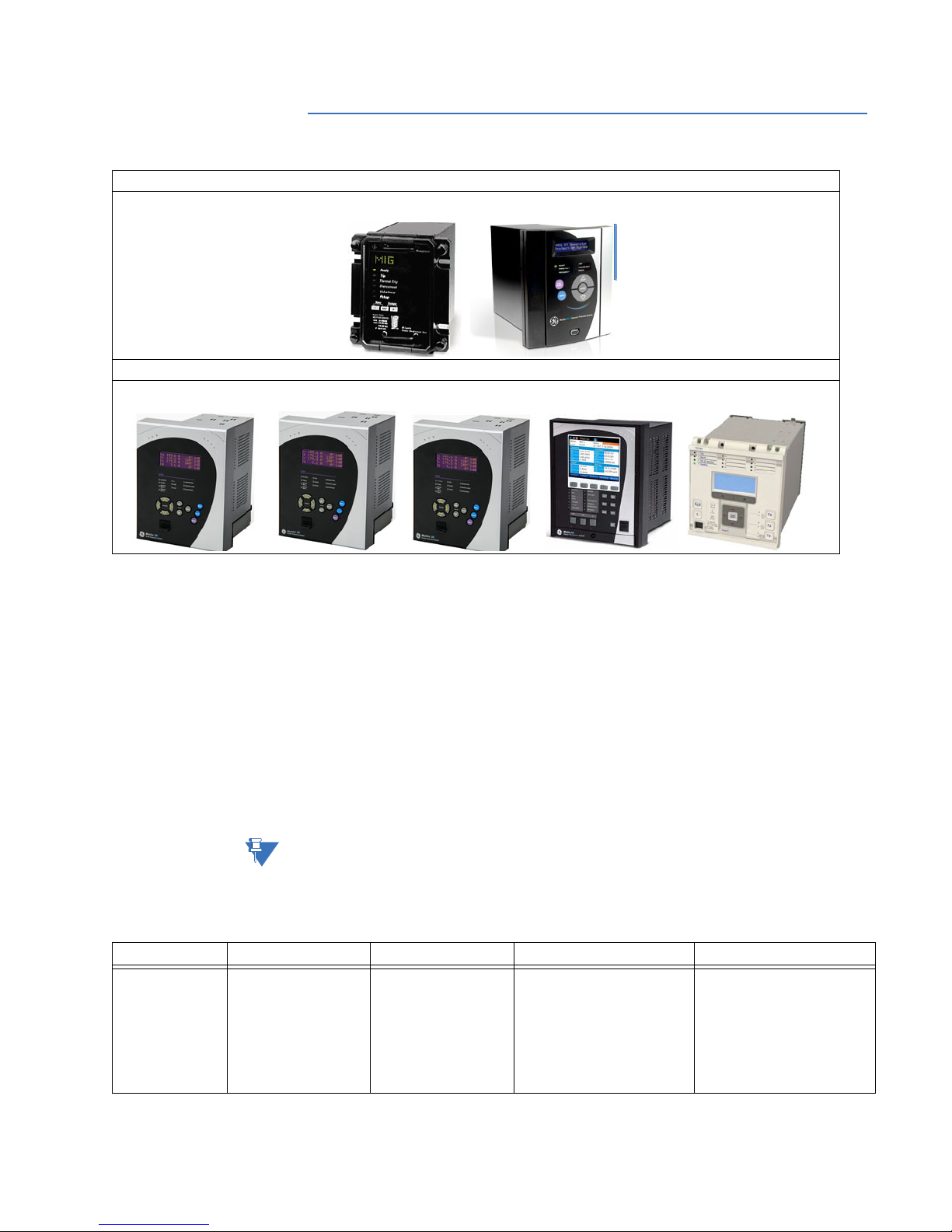
1.4 MIG and MIG II relays
Installed Relay
MIG II Generator Protection System
MIG Machine Protection Relay
Retrofit Relay
350 Feeder Protection System, 345 Transformer Protection System, 339 Motor Protection System, 850 Feeder Protection System,
or P40 Agile P14D Relay
Most MIG and MIG II features are available in 350, 345, or 339 relays as described in the
tables below. In some cases an 8 Series or P40 Agile relay may be required to replace full
functionality. For additional information, refer to the P40 Technical Manual or
850
Instruction Manual.
1.4.1 MIG and MIG II P to 350 or 345
For the MIG II P being used as a transformer, when 87R is not required, the 350 relay is an
option. When 87R is required, the 345 relay with 87G is an option.
For the MIG II P being used as a generator, the 350 relay is an option.
Note
Feature MIG MIG II P
Protection &
Control
Current Unbalance: 46
Thermal Protection: 49
IOC: 50P, 50G, 51G
TOC: 51P
Undercurrent: 37
66
Restricted Ground
Differential: 87R
The 350 Feeder Protection System does not support Restricted Ground Differential 87R. To
replace MIG and MIG II P relays when Restricted Ground Fault protection is required, the
345 relay with 87G can be used. a P40 Agile P14D relay or 850 Feeder Protection System
can also be used.
Current Unbalance: 46
Thermal Protection: 49
IOC: 50N, 50P, 50G
TOC: 51G, 51N, 51P
Restricted Ground
Differential: 87R
1
350
Current unbalance:
51_2 or 46(1), 50_2 (1) or 46(1)
Thermal Protection: 49
IOC: 50P(2), 50G/SG(2), 50N(2),
TOC: 51P(1), 51G/SG(1), 51N(1),
Other Protection: I1/I2(46BC)
2
345
Current unbalance:
51_2 or 46(1), 50_2 (1) or 46(1)
Thermal Protection: 49
IOC: 50P(2), 50G/SG(2), 50N(2),
TOC: 51P(1), 51G/SG(1), 51N(1),
Restricted Ground Fault:
87G/RGF(2)
3 SERIES RETROFIT – INSTRUCTION MANUAL 7
Page 14

MIG AND MIG II RELAYS CHAPTER 1: OVERVIEW
Feature MIG MIG II P
Metering &
Monitoring
Oscillography 8 samples/cycle
Communications Serial (RS232, RS485)
Hardware 2 digital outputs
1. For additional features, refer to the 350 Instruction Manual.
2. For additional features, refer to the 345 Instruction Manual.
Metering
Event Recording
maximum length 24
cycles
protocols: Modbus RTU
6 relay outputs
Configurable I/O
Configurable Logic
2 fixed LEDs
4 configurable LEDs
Metering
Event Recording
8 samples/cycle
maximum length 24
cycles
Serial (RS232, RS485)
protocols: Modbus RTU
2 digital inputs
6 digital outputs
Configurable I/O
Configurable Logic
2 fixed LEDs
4 configurable LEDs
The following table describes MIG II P options, and the equivalent 350 and 345 options and
order codes. In some cases the 350/345 options have changed from those available for
MIG II relays, so read the descriptions carefully.
1
350
Metering
Event Recording
up to 32 samples per cycle
(user-selectable)
maximum length 192 cycles
USB
Serial (RS485) protocols:
Modbus RTU, DNP 3.0, IEC
60870-5-103
Ethernet protocols: Modbus
TCP/IP, DNP 3.0, IEC 60870-5104, IEC 61850 GOOSE, IEC
61850, OPC-UA
10 inputs
7 outputs (2 Form A, 5 Form C)
Configurable I/O
Configurable Logic
10 LEDs (non-programmable
LEDs)
12 LEDs (programmable LEDs)
2
345
Metering
Event Recording
up to 32 samples per cycle
(user-selectable)
maximum length 192 cycles
USB
Serial (RS485) protocols:
Modbus RTU, DNP 3.0, IEC
60870-5-103
Ethernet protocols: Modbus
TCP/IP, DNP 3.0, IEC 60870-5104, IEC 61850 GOOSE, IEC
61850, OPC-UA
10 inputs
7 outputs (2 Form A, 5 Form C)
Configurable I/O
Configurable Logic
10 LEDs (non-programmable
LEDs)
12 LEDs (programmable LEDs)
Feature MIG order code options MIG II P order code options 350/345 order code options
Application n/a MIGII-P-A11E00HI00
P: Generator Protection Elements
350EP0G0HE-M-NNSNNN
M: Advanced configuration: User
selectable 49, 50P(2), 50G/SG(2),
50N(2), 51P(1), 51G/SG(1), 51N(1),
51_2 or 46(1), 50_2 (1) or 46(1), I1/
I2(46BC)
345EP0G0HE-M-NNSNNN
M: Advanced configuration: 87T,
87T-50, 51P(2), 51N(2), 51G(2),
50P(2), 50G(2), 50N(2), 49P, 46 (51_2/
50_2)(2), 86, 50BF(2), 87G/RGF(2)
Curves MIGP-A-11E000F00C
MIGIIP-A-11E00HI00
All 350 and 345 relays come with
ANSI, IEC, and IAC curves standard.
A: ANSI Curves
I: IEC Curves
Phase CT Range MIGPA-1-1E000F00C
1: Phase CT = 1 A (0.1 - 2.4 A)
5: Phase CT = 5 A (0.5 - 12 A)
A: ANSI Curves
I: IEC Curves
MIFIIPA-1-1E00HI00
0: Phase CT = 1/5 A
1: Phase CT = 1 A
3xxE-P0-G0HEMNNSNNN
P0: P0 user selectable 1/5 A three-
phase current inputs
5: Phase CT = 5 A
Ground CT
MIGPA1-1-E000F00C
MIGIIPA1-1-E00HI00
3xxEP0-G0-HEMNNSNNN
Range
1: Ground CT In = 1 A (0.1 - 2.4 A)
5: Ground CT In = 5 A (0.5 - 12 A)
N: Sensitive Ground CT In = 1 A
(0.005 - 0.12 A)
1: Ground CT In = 1 A (0.1 - 2.4 A)
5: Ground CT In = 5 A (0.5 - 12 A)
N: Sensitive Ground (0.005 - 0.12 A)
G0: user selectable 1/5 A Ground
current input (0.02 - 20 × CT)
S0: user selectable 1/5 A Sensitive
Ground current input (0.002 - 3 × CT)
8 3 SERIES RETROFIT – INSTRUCTION MANUAL
Page 15

CHAPTER 1: OVERVIEW MIG AND MIG II RELAYS
NOTE
Feature MIG order code options MIG II P order code options 350/345 order code options
Power Supply MIGPA11E000-F-00C
MIGIIPA11E00-HI-00
3xxEP0G0-H-EENNSNNN
H:
110 - 250 VDC (Range: 88~300 VDC)
110 - 230 VAC (Range: 88~264 VAC)
F: 24 - 48 VDC (Range: 19~58 VDC)
Note
Order codes are subject to change without notice. See the GE Multilin website at: http://
HI:
110 - 250 VDC (Range: 88~300 VDC)
110 - 230 VAC (Range: 88~264 VAC)
LO: 28 - 48 VDC (Range: 19~58 VDC)
www.gegridsolutions.com/multilin for up-to-date order codes.
1.4.2 MIG and MIG II Q to 339
Feature MIG MIG II Q
Protection &
Control
Metering &
Monitoring
Oscillography 8 samples/cycle maximum length
Communications Serial (RS232, RS485)
Hardware 2 digital outputs
1. For additional features, refer to the 339 Instruction Manual.
Current Unbalance: 46
Thermal Protection: 49
IOC: 50P, 50G, 51G
TOC: 51P
Undercurrent: 37
66
Restricted Ground Differential: 87R
24 cycles
protocols: Modbus RTU
6 relay outputs
Configurable I/O
Configurable Logic
2 fixed LEDs
4 configurable LEDs
Current Unbalance: 46
Acceleration Time: 48
Thermal Protection: 49
IOC: 50N, 50P, 50G
TOC: 51G, 51N, 51P
Undercurrent: 37
66
Metering
Event Recording
8 samples/cycle
maximum length 24 cycles
Serial (RS232, RS485)
protocols: Modbus RTU
2 digital inputs
6 digital outputs
Configurable I/O
Configurable Logic
2 fixed LEDs
4 configurable LEDs
H: 110 - 250 VDC
110 - 230 VAC
L: 28 - 48 VDC
1
339
Current Unbalance: 46
Acceleration Time: 48
Thermal Protection: 49
IOC: 50G/SG(1), 50L, 50N(1), 50P(1)
TOC: 51N(1), 51P(1), 51R
Undercurrent: 37
66
Other Protection: 86, 50BF
Metering
Event Recording
up to 32 samples per cycle
(user-selectable)
maximum length 192 cycles
USB
Serial (RS485) protocols: Modbus RTU,
DNP 3.0, IEC 60870-5-103
Ethernet protocols: Modbus TCP/IP,
DNP 3.0, IEC 60870-5-104, IEC 61850
GOOSE, IEC 61850
10 inputs
7 outputs (2 Form A, 5 Form C)
Configurable I/O
Configurable Logic
10 LEDs (non-programmable LEDs)
12 LEDs (programmable LEDs)
3 SERIES RETROFIT – INSTRUCTION MANUAL 9
Page 16

MIG AND MIG II RELAYS CHAPTER 1: OVERVIEW
NOTE
The following table describes MIG and MIG II Q options, and the equivalent 339 options and
order codes. In some cases the 339 options have changed from those available for MIG
and MIG II relays, so read the descriptions carefully.
Feature MIG order code options MIG II Q order code options 339 order code options
Application n/a MIGII-Q-A11E00HI00
339EP0G0HE-S-NNSNNN
Curves MIGP-A-11E000F00C
A: ANSI Curves
I: IEC Curves
Phase CT Range MIGPA-1-1E000F00C
1: Phase CT = 1 A (0.1 - 2.4 A)
5: Phase CT = 5 A (0.5 - 12 A)
Ground CT
MIGPA1-1-E000F00C
Range
1: Ground CT In = 1 A (0.1 - 2.4 A)
5: Ground CT In = 5 A (0.5 - 12 A)
N: Sensitive Ground CT In = 1 A
(0.005 - 0.12 A)
Power Supply MIFPA111-F-C
H:
110 - 250 VDC (Range: 88~300 VDC)
110 - 230 VAC (Range: 88~264 VAC)
F: 24 - 48 VDC (Range: 19~58 VDC)
Note
Order codes are subject to change without notice. See the GE Multilin website at: http://
www.gegridsolutions.com/multilin for up-to-date order codes.
Q: Motor Protection Elements
MIGIIQ-A-11E00HI00
A: ANSI Curves
I: IEC Curves
MIGIIQA-1-1E00HI00
1: Phase CT = 1 A (0.1 - 2.4 A)
5: Phase CT = 5 A (0.5 - 12 A)
MIGIIQA1-1-E00HI00
1: Ground CT In = 1 A (0.1 - 2.4 A)
5: Ground CT In = 5 A (0.5 - 12 A)
N: Sensitive Ground CT In = 1 A
(0.005 - 0.12 A)
MIFIIQA11E00-HI-00
HI:
110 - 250 VDC (Range: 88~300 VDC)
110 - 230 VAC (Range: 88~264 VAC)
LO: 28 - 48 VDC (Range: 19~58 VDC)
S: Standard configuration: 37, 46,
48, 49, 50P(1), 50G/SG(1), 50N(1),
50L,51R, 66, 86, 51N(1), 51P(1), 50BF
All 339 relays come with ANSI, IEC,
and IAC curves standard.
339E-P0-G0HESNNSNNN
P0: user selectable 1/5 A three-
phase current inputs (0.02 - 20 × CT)
339EP0-G0-HESNNSNNN
G0: user selectable 1/5 A Ground
current input (0.02 - 20 × CT)
All 339 relays come with CBCT
(50:0.025) standard.
339EP1G1-H-ESNNSNNN
H: 110 - 250 VDC
110 - 230 VAC
L: 28 - 48 VDC
10 3 SERIES RETROFIT – INSTRUCTION MANUAL
Page 17

CHAPTER 1: OVERVIEW MIN AND MIN II RELAYS
1.5 MIN and MIN II relays
Installed Relay Retrofit Relay
MIN II Ground Protection System
MIN Digital Ground Protection
Most MIN and MIN II features are available in 350 relays as described in the table below:
350 Feeder Protection System,
or P40 Agile Relay
Feature MIN
Protection &
Control
Metering &
Monitoring
Oscillography 8 samples/cycle
Communications Serial (RS232, RS485)
Hardware 2 digital outputs
1. For a detailed example of converting the MIN II Option "S" 67IG1 function to the 350 32N function, see Converting MIN II 67IG1 to 350
32N on page 29.
2. For additional features, refer to the 350 Instruction Manual.
Directional: 67N1, 67N2
IOC: 50GH, 50GL
TOC: 51GH, 51GL
Cold Load Pickup: CLP
Breaker Failure: 50BF
Metering
Breaker Health
Event Recording
maximum length 24 cycles
protocols: Modbus RTU
6 relay outputs
Configurable I/O
Configurable Logic
2 fixed LEDs
4 configurable LEDs
67G1, 67G2, 67PC1, 67PC2
50G1, 50G2
51G1, 51G2
Metering
Event Recorder
8 samples/cycle
maximum length 24 cycles
Serial (RS232, RS485)
protocols: Modbus RTU
2 digital inputs
6 digital outputs
Configurable I/O
Configurable Logic
2 fixed LEDs
4 configurable LEDs
MIN II
1
Directional: 67P(1), 67N(1), 67G/SG(1)
IOC: 50P(2), 50N(2), 50_2, 50G/SG(2)
TOC: 51P(1), 51G/SG(1), 51N(1)
Cold Load Pickup: CLP
Breaker Failure: 50BF
Other: 49, 32N(2), VTFF + Voltage,
Power, and Energy Metering, 60CTS
Metering
Breaker Health
Event Recording
up to 32 samples per cycle
(user-selectable)
maximum length 192 cycles
USB
Serial (RS485) protocols: Modbus RTU,
DNP 3.0, IEC 60870-5-103
Ethernet protocols: Modbus TCP/IP,
DNP 3.0, IEC 60870-5-104, IEC 61850
GOOSE, IEC 61850, OPC-UA
10 inputs
7 outputs (2 Form A, 5 Form C)
Configurable I/O
Configurable Logic
10 LEDs (non-programmable LEDs)
12 LEDs (programmable LEDs)
350
2
3 SERIES RETROFIT – INSTRUCTION MANUAL 11
Page 18

MIN AND MIN II RELAYS CHAPTER 1: OVERVIEW
NOTE
The following table describes MIN and MIN II options, and the equivalent 350 options and
order codes. In some cases the 350 options have changed from those available for MIN
and MIN II relays, so read the descriptions carefully.
Feature MIN order code options MIN II order code options 350 order code options
Function MIN-N-A0E000H00C
MINII-N-A0EE00HI00
350EP0G0HE-E-N-R-SNNN
N: Ground directional relay
L1: Ground directional relay for
teleprotection schemes
N: Ground directional relay
L: Ground directional relay for
teleprotection schemes
Current Protection E: Extended
configuration: User selectable 49,
50P(2), 50G/SG(2), 50N(2), 51P(1),
51G/SG(1), 51N(1)
Other Options R: Phase, Neutral, and
Ground Directional Overcurrent
Protection: 67P(1), 67N(1), 67G/SG(1),
32N(2), VTFF + Voltage, Power, and
Energy Metering, 60CTS
Curves MINN-A-0E000H00C
A: ANSI Curves
I: IEC Curves
MINIIN-A-0EE00HI00
A: ANSI Curves
All 350 relays come with ANSI, IEC,
and IAC curves standard.
I: IEC Curves
Ground CT
MINNA0-E-000H00C
MINIINA0-E-E00HI00
350EP0-G0-HEENRSNNN
Range
E: Ground CT In = 1 A or 5 A (10240% of CT rating)
S2: Isolated ground and Peterson
coil
Power Supply MINNA0E000-H-00C
H:
110 - 250 VDC (Range: 88~300 VDC)
110 - 230 VAC (Range: 88~264 VAC)
F: 24 - 48 VDC (Range: 19~58 VDC)
Environmental
n/a MINIINA0EE00HI-00
E: Ground CT In = 1 A or 5 A (10240% of CT rating)
S2: Isolated ground3 and Peterson
coil
MINIINA0EE00-HI-00
HI:
110 - 250 VDC (Range: 88~300 VDC)
110 - 230 VAC (Range: 88~264 VAC)
LO: 28 - 48 VDC (Range: 19~58 VDC)
G0: user selectable 1/5 A Ground
current input (0.02 - 20 × CT)
S0: user selectable 1/5 A Sensitive
Ground current input (0.002 - 3 × CT)
350EP0G0-H-EENRSNNN
H: 110 - 250 VDC
110 - 230 VAC
L: 28 - 48 VDC
350EP0G0HEENRSNN-N
Option
00: None
0H: Conformal Coating
N: None
H: Harsh Environment Conformal
Coating
1. Option L is not available in the 3 Series.
2. Option S is not directly replaced in the 350 Feeder Protection System, however the Wattmetric Ground Fault element (32N) is a
substitute for MINII option S and detects feeder/line ground faults in solidly grounded, ungrounded, resistance grounded and res
onance grounded networks. It provides equivalent functionality to the Isolated Ground and Petersen Coil elements of the MIN II
relay.
Option S directional ground fault for Isolated or Peterson Coil grounded networks may also be replaced by P40 Agile P14D relays.
The P40 Agile P14D relay uses different algorithms to achieve more accurate High Impedance Fault detection; refer to the
P14D
Technical Manual, Chapter 6, Section 18.
3. For a detailed example of converting the MIN II Option "S" 67IG1 Isolated Ground function to the 350 32N function, see Converting
MIN II 67IG1 to 350 32N on page 29.
-
Note
Order codes are subject to change without notice. See the GE Multilin website at: http://
www.gegridsolutions.com/multilin for up-to-date order codes.
12 3 SERIES RETROFIT – INSTRUCTION MANUAL
Page 19

CHAPTER 1: OVERVIEW MIW AND MIW II RELAYS
1.6 MIW and MIW II relays
Installed Relay Retrofit Relay
MIW II Directional Power Protection System 350 Feeder Protection System or 889 Generator Protection System
Most MIW and MIW II features are available in 350 relays as described in the table below.
In some cases an 8 Series relay may be required to replace full functionality.
Feature MIW MIW II
Protection &
Control
Metering &
Monitoring
Oscillography 8 samples/cycle
Communications Serial (RS232, RS485)
Hardware 2 digital outputs
1. For additional features, refer to the 350 Instruction Manual.
Directional Power: 32RP, 32FP, 32LF
40
60
maximum length 24 cycles
protocols: Modbus RTU
6 relay outputs
Configurable I/O
Configurable Logic
2 fixed LEDs
4 configurable LEDs
Directional Power: 32(4)
40
60
Metering
Event Recording
Configurable IO and LEDs
Configurable Logic
8 samples/cycle
maximum length 24 cycles
Serial (RS232, RS485)
protocols: Modbus RTU
2 digital inputs
6 digital outputs
Configurable I/O
Configurable Logic
2 fixed LEDs
4 configurable LEDs
1
350
Directional Power: 32(2)
Other Protection: 27P(2), 27X(1),
27P_1 (1), 59P(2), 59N(1), 59X(1),
59_2(1), 81O(2), 81U(2), 67P(1),
67N(1), 67G/SG(1), VTFF(1), 25(1),
60CTS
Metering
Breaker Health
Event Recording
Programmable Logic Elements
...
up to 32 samples per cycle
(user-selectable)
maximum length 192 cycles
USB
Serial (RS485) protocols: Modbus
RTU, DNP 3.0, IEC 60870-5-103
Ethernet protocols: Modbus TCP/IP,
DNP 3.0, IEC 60870-5-104, IEC 61850
GOOSE, IEC 61850, OPC-UA
10 inputs
7 outputs (2 Form A, 5 Form C)
Configurable I/O
Configurable Logic
10 LEDs (non-programmable LEDs)
12 LEDs (programmable LEDs)
3 SERIES RETROFIT – INSTRUCTION MANUAL 13
Page 20

MIW AND MIW II RELAYS CHAPTER 1: OVERVIEW
NOTE
The following table describes MIW and MIW II options, and the equivalent 350 options and
order codes. In some cases the 350 options have changed from those available for MIW
and MIW II relays, so read the descriptions carefully.
Feature MIW order code options MIW II order code options 350 order code options
Function n/a MIWII-1-000E00HI00
350EP0G0HEEN-W-SNNN
11: 3x Directional Power, 1x Loss of
Field, 1x Fuse Failure
2: 4x Directional Power
W: Advanced Protection: 27P(2),
27X(1), 27P_1 (1), 59P(2), 59N(1),
59X(1), 59_2(1), 81O(2), 81U(2),
67P(1), 67N(1), 67G/SG(1), VTFF(1),
25(1), 60CTS, 32(2)
Power Supply MIW1000E000-F-00C
H:
110 - 250 VDC (Range: 88~300 VDC)
110 - 230 VAC (Range: 88~264 VAC)
F: 24 - 48 VDC (Range: 19~58 VDC)
1. To replace model MIW II 1000 and the Loss of Excitation protection function, refer to the 889 Instruction Manual.
Note
Order codes are subject to change without notice. See the GE Multilin website at: http://
MIWII1000E00-HI-00
HI:
110 - 250 VDC (Range: 88~300 VDC)
110 - 230 VAC (Range: 88~264 VAC)
LO: 28 - 48 VDC (Range: 19~58 VDC)
350EP0G0-H-EENWSNNN
H: 110 - 250 VDC
110 - 230 VAC
L: 28 - 48 VDC
www.gegridsolutions.com/multilin for up-to-date order codes.
14 3 SERIES RETROFIT – INSTRUCTION MANUAL
Page 21

CHAPTER 1: OVERVIEW 239 RELAYS
1.7 239 relays
Installed Relay Retrofit Relay
239 Motor Protection Relay 339 Motor Protection System
239 features are available in 339 relays as described in the table below:
Feature
Protection &
Control
Monitoring &
Metering
Communications RS485 port USB
Hardware 2 inputs and 3 fixed inputs.
1. The 239 relay with MOD 509 is designed to provide ground directional protection. Similar protection can be obtained using the 339 relay neutral instantaneous protection using either the
current, voltage, or both.
2. For additional features, refer to the 339 Instruction Manual.
Undercurrent/minimum load: 37
Motor/load bearing, Overtemperature: 38
Mechanical jam:39
Current unbalance: 46
Stator winding overtemperature: 49
Phase short circuit: 50
Timed overload: 51
Ground fault instantaneous or definite
time: 50G/50N
Alarm relay: 74
Lockout and trip relay: 86/94
Metering
Event Recording
4 Form C contacts
6 Fixed LEDs
239
1
Undercurrent: 37
Current Unbalance: 46
Acceleration Time: 48
Thermal Protection: 49
IOC: 50G/SG(1), 50L, 50N(1), 50P(1)
TOC: 51N(1), 51P(1), 51R
Other Protection: 66, 86, 50BF
Metering
Event Recording
Serial (RS485) protocols: Modbus
RTU, DNP 3.0, IEC 60870-5-103
Ethernet protocols: Modbus TCP/IP,
DNP 3.0, IEC 60870-5-104, IEC
61850 GOOSE, IEC 61850
10 inputs
7 outputs (2 Form A, 5 Form C)
Configurable I/O
Configurable Logic
8 configurable and 4 fixed LEDs
10 fixed LED (drawout unit)
12 fixed LEDs (non-drawout unit)
339
2
3 SERIES RETROFIT – INSTRUCTION MANUAL 15
Page 22

239 RELAYS CHAPTER 1: OVERVIEW
NOTE
The following table describes 239 options, and the equivalent 339 options and order codes.
In some cases the 339 options have changed from those available for 239 relays, so read
the descriptions carefully.
Note
Order codes are subject to change without notice. See the GE Multilin website at: http://
www.gegridsolutions.com/multilin for up-to-date order codes.
Feature 239 order code options 339 order code options
Application 239RTD-AN-H
AN: Single isolated, analog output:
0 – 1, 0 – 20, 4 – 20 mA
Programmable output parameters:
thermal capacity,% full load, phase
current, RTD1, RTD2, RTD3 temperature
Phase CT
239 standard phase CT Input:
Range
1 A and 5 A secondary
Range: 0.1 to 11 x phase CT primary
Ground CT
239 standard ground CT input:
Range
5 A secondary and 50:0.025
Range:
0.03 to 1.4 x CT primary (5 A CT)
0.05 to 16.0 A (50:0.025 CT)
Power
Supply
239 standard power supply:
90 – 300 VDC or 70 – 265 VAC,
50 / 60 Hz
Harsh
239RTDAN-H
Environment
H: Harsh Environment Conformal
Coating
RTDs 239-RTD-ANH
3 RTDs: stator/bearing; programmable
type: platinum, nickel, copper
339EP0G0HE-S-NNSNNH
S: Standard configuration: 37, 46, 48, 49,
50P(1), 50G/SG(1), 50N(1), 50L,51R, 66,
86, 51N(1), 51P(1), 50BF
339E-P0-G0HESNNSNNH
P0: user selectable 1/5 A three-phase
current inputs (0.02 - 20 × CT)
339EP0-G0-HESNNSNNH
G0: user selectable 1/5 A Ground current
input (0.02 - 20 × CT)
All 339 relays come with CBCT (50:0.025)
standard.
339EP1G1-H-ESNNSNNH
H: 110 - 250 VDC
110 - 230 VAC
L: 28 - 48 VDC
339EP1G1HESNNSNN-H
H: Harsh Environment Conformal
Coating
The 339 can support 3 - 100 ohm Pt
RTDs.
The RMIO module supports up to
12 - 100 ohm Pt RTDs.
16 3 SERIES RETROFIT – INSTRUCTION MANUAL
Page 23

CHAPTER 1: OVERVIEW 735/737 RELAYS
1.8 735/737 relays
Installed Relay Retrofit Relay
735/737Feeder Protection System 350 Feeder Protection System
735 and 737 features are available in 350 relays as described in the table below.
Feature 735/737
Protection &
Control
Metering &
Monitoring
Communications RS485 2-wire communications
Hardware 8 LED trip indicators
1. For additional features, refer to the 350 Instruction Manual.
50/51, 50G/51G 50P(2), 50G/SG(2), 50N(2), 51P(1),
Current Metering shown in % Metering
or RS422 4-wire communications
4 LED status indicators
3 standard outputs
737 has 8 additional output relays to
provide separate dry contact
outputs for each overcurrent
protection element.
1
350
51G/SG(1), 51N(1)
User selectable 49, 86
Breaker Health
Event Recording
Programmable Logic Elements
...
USB
Serial (RS485) protocols: Modbus
RTU, DNP 3.0, IEC 60870-5-103
Ethernet protocols: Modbus TCP/IP,
DNP 3.0, IEC 60870-5-104, IEC 61850
GOOSE, IEC 61850, OPC-UA
10 inputs
7 outputs (2 Form A, 5 Form C)
Configurable I/O
Configurable Logic
8 configurable and 4 fixed LEDs
10 fixed LED (drawout unit)
12 fixed LEDs (non-drawout unit)
3 SERIES RETROFIT – INSTRUCTION MANUAL 17
Page 24

735/737 RELAYS CHAPTER 1: OVERVIEW
The following table describes 735 and 737 options, and the equivalent 350 options and
order codes. In some cases the 350 options have changed from those available for 735/
737 relays, so read the descriptions carefully.
Feature 735/737 order code options 350 order code options
Function 735-55HI485
735: Standard 735 Relay with 50/51,
50G/51G protection
737: 737 Relay (same as 735 with 8
additional output relays)
Phase CT Range 735-5-5HI485
1: 1 A Phase CT Secondaries 5: 5 A
Phase CT Secondaries
Ground CT
7355-5-HI485
Range
1: 1 A Ground CT Secondaries 5: 5 A
Ground CT Secondaries
Power Supply 73555-HI-485
HI: 90 to 300 V DC; 70 to 265 V AC at
50/60 Hz
LO: 20 to 60 V DC; 20 to 48 V AC at
50/60 Hz
Comms 73555HI-485
350EP0G0HE-E-NNSNDN
E: Extended configuration: User
selectable 49, 50P(2), 50G/SG(2),
50N(2), 51P(1), 51G/SG(1),
51N(1)
350E-P0-G0HEENNSNDN
P0: P0 user selectable 1/5 A threephase current inputs
350EP0-G0-HEENNSNDN
G0: user selectable 1/5 A Ground
current input (0.02 - 20 × CT)
350EP0G0-H-EENNSNDN
H: 110 - 250 VDC
110 - 230 VAC
L: 28 - 48 VDC
350EP0G0HEENN-SN-DN
485: RS485 2-wire communications
(standard)
422: RS422 4-wire communications
SN: Standard: Front USB, Rear
RS485: Modbus RTU, DNP3.0, IEC
60870-5-103
(optional)
Note
Order codes are subject to change without notice. See the GE Multilin website at: http://
www.gegridsolutions.com/multilin for up-to-date order codes.
18 3 SERIES RETROFIT – INSTRUCTION MANUAL
Page 25

CHAPTER 1: OVERVIEW MLJ AND TOV RELAYS
1.9 MLJ and TOV relays
Installed Relay Retrofit Relay
MLJ Digital Synchronism Check
Relay
350 Feeder Protection System, option V
or P40 Agile P14D Relay
TOV Modular Voltage Relay
Most MLJ and TOV features are available in 350 relays as described in the table below:
Feature MLJ TOV
Protection &
Control
Communications Serial (RS232, RS485, fiber)
Hardware 2 digital outputs
1. For additional features, refer to the 350 Instruction Manual.
UV: 27
Synchrocheck: 25
protocols: GEPCE
6 relay outputs
Configurable I/O
Configurable Logic
3 fixed LEDs
UV: 27
OV: 59
2 digital inputs
6 digital outputs
Configurable I/O
Configurable Logic
3 fixed LEDs
350 Feeder Protection System, option V,
or P40 Agile P14D Relay
UV: 27P(4), 27X(1), 27P_1(1)
OV: 59P(4), 59N(4), 59X(1), 59_2(2)
Underfrequency: 81U(4)
Overfrequency: 81O(4)
Synchrocheck: 25(1)
Voltage Fuse Failure: VTFF(1)
USB
Serial (RS485) protocols: Modbus RTU,
DNP 3.0, IEC 60870-5-103
Ethernet protocols: Modbus TCP/IP,
DNP 3.0, IEC 60870-5-104, IEC 61850
GOOSE, IEC 61850, OPC-UA
10 inputs
7 outputs (2 Form A, 5 Form C)
Configurable I/O
Configurable Logic
8 configurable and 4 fixed LEDs
10 fixed LED (drawout unit)
12 fixed LEDs (non-drawout unit)
350
1
For voltage and frequency functionality, P40 Agile P94V Voltage and Frequency IEDs are
another option. Refer to the P40 Agile P94V Technical Manual for details.
3 SERIES RETROFIT – INSTRUCTION MANUAL 19
Page 26

MLJ AND TOV RELAYS CHAPTER 1: OVERVIEW
NOTE
The following table describes MLJ and TOV options, and the equivalent 350 options and
order codes. In some cases the 350 options have changed from those available for MLJ
and TOV relays, so read the descriptions carefully.
Feature MLJ order code options TOV 4 order code options 350 order code options
Application n/a TOV-4-013I030F00C
4: 3 Phase voltage relay
5: Single Phase
Function n/a TOV4013-I-030F00C
All 350 relays come with 3 phase
and ground standard.
350E-PXGX-HE-N-N-V-SNNN
I: Undervoltage
M: Overvoltage
Protocol MLJ100-5-B010F00C
n/a 350EPXGXHENENV-SN-NN
5: RS485 communications
6: RS485 + RS232 + plastic fiber
optics communications
7: RS485 + RS232 + glass fiber
optics communications
Power Supply MLJ1005B010-F-00C
H: 110/250 VDC input and auxiliary
voltage
F: 24/48 VDC input and auxiliary
voltage
1. For details of 350 communications implementation, see the 3 Series Communications Guide.
Note
Order codes are subject to change without notice. See the GE Multilin website at: http://
TOV4013I030-F-00C
F: Aux voltage 24 - 48 VDC/VAC
G: Aux voltage 48 - 125 VDC/VAC
H: Aux voltage 110 - 240 VDC,
110 - 220 VAC
www.gegridsolutions.com/multilin for up-to-date order codes.
V: Voltage Metering - 27P(4), 27X(1),
27P_1(1), 59P(4), 59N(4), 59X(1),
59_2(2), 81O(4), 81U(4), 25(1), VTFF(1)
SN: Standard: Front USB, Rear
RS485: Modbus RTU, DNP3.0,
IEC60870-5-103
1
350EPXGX-H-ENNVSNNN
H: 110 - 250 VDC
110 - 230 VAC
L: 28 - 48 VDC
20 3 SERIES RETROFIT – INSTRUCTION MANUAL
Page 27

CHAPTER 1: OVERVIEW FINDING YOUR M AND MII FAMILY RELAY ORDER CODE
1.10 Finding your M and MII Family relay order code
M Family (MIF, MIG, MIN, MIV, and MIW) relay order codes are in the format MIFPA111FC,
and are shown on the faceplate of the relay. The order code is also shown on the relay
display from the Information menu, and can be found in the Enervista MII Setup software
under File > Properties.
MII Family (MIF II, MIG II, MIN II, MIV II, MIW II, and MIB) relay order codes are in the format
MIFIIPA11E00HI00. To find the order code for your existing MII relay, check the label on the
side of the relay. The model listed on the label is the complete order code. The order code is
also shown on the relay display, and can be found in the Enervista MII Setup software
under File > Properties.
3 SERIES RETROFIT – INSTRUCTION MANUAL 21
Page 28

FINDING YOUR M AND MII FAMILY RELAY ORDER CODE CHAPTER 1: OVERVIEW
22 3 SERIES RETROFIT – INSTRUCTION MANUAL
Page 29

GE
NOTE
Grid Solutions
3 Series Retrofit
Chapter 2: Converting Settings
Files
Converting Setting s Files
Before any mechanical or electrical changes are made, the settings file from the Multilin
MII relay in use must be backed up. The existing settings file can then be converted to a
3
Series settings file. All converted settings and new settings (set to default values) must be
carefully reviewed before the file is uploaded to the new 3
Series relay.
Note
Settings file conversion is currently available for converting most MIF II and MIV II relay
settings files to EnerVista 3 Series Setup software version 2.3x files.
Table 2–1: File conversion support
Series release 2.3x
for 3
MII models FW versions
MIFP V2.14
MIFIIP V301
MIFIIP V502
All MIV II models V310
V401
V402
V403
V404
V503
V504
V505
V506
V507
V401
V402
V403
V404
V405
3 SERIES RETROFIT – INSTRUCTION MANUAL 23
Page 30

DOWNLOADING AND SAVING MIF II OR MIV II SETPOINT FILES CHAPTER 2: CONVERTING SETTINGS FILES
NOTE
2.1 Downloading and saving MIF II or MIV II setpoint files
Use the following procedure to download and save MIF II or MIV II setpoint files to a local
PC.
4.Note the location of the saved setpoint file. Two files will be generated, *.txt and *.ajs,
and both are necessary for converting to *.sr3 setting file.
1. Start the EnerVista MII Setup software.
Note
Only MIF II or MIV II setpoint files from EnerVista MII Setup version 2.70 and firmware
versions listed at the beginning of this chapter are supported for conversion. Older file
versions must be converted to the latest version using the latest EnerVista MII Setup
software.
To download the latest MII setup software, see http://www.gegridsolutions.com
Ensure that the site and corresponding device(s) have been properly defined and
configured. (Refer to the MIF II Instruction Manual for more information on the
Enervista MII Setup software.)
2. Obtain settings information from the connected relay using File > Get info from relay.
3. The EnerVista MII Setup software prompts for the name and destination path of the
setpoint file. The corresponding file extension is automatically assigned (*.ajs). Press
Save to complete the process. After a few seconds of data retrieval the file is saved.
4. Note the location of the saved setpoint file. Two files will be generated: *.txt and *.ajs.
Both files are needed for conversion to a *.sr3 setting file.
24 3 SERIES RETROFIT – INSTRUCTION MANUAL
Page 31

CHAPTER 2: CONVERTING SETTINGS FILES CONVERTING A SAVED MIF II OR MIV II SETPOINT FILE
NOTE
2.2 Converting a saved MIF II or MIV II setpoint file
The Enervista 3 Series Setup software allows the user to create new setpoint files based on
existing MII setpoint files. These can be uploaded to a relay at a later date. The following
procedure illustrates how to convert existing MII setpoint files.
Note
Only MIF II and MIV II setpoint files from EnerVista MII Setup version 2.70 and firmware
versions listed at the beginning of this chapter are supported for conversion.
1. Install and start the latest version of the EnerVista 3 SeriesSetup software (available
from the GE EnerVista CD or Website). (See the 350 Feeder Protection Instruction
Manual for more information.)
2. Select Offline > New Settings File from the top menu bar. The following box appears,
allowing for the configuration of the setpoint file for the correct firmware version and
relay order code.
3 SERIES RETROFIT – INSTRUCTION MANUAL 25
It is important to define the correct firmware version and order code to ensure that
only available setpoints are downloaded into the relay.
Page 32

CONVERTING A SAVED MIF II OR MIV II SETPOINT FILE CHAPTER 2: CONVERTING SETTINGS FILES
NOTE
If the MIF II or MIV II setpoint file cannot be converted due to an incompatible 350
order code, the following message is shown.
Notehe one that is added in
3. Select the Firmware Version, and Order Code options for the new setpoint file.
4. For future reference, enter some useful information in the Description box to facilitate
the identification of the device and the purpose of the file.
5. To select a file name and path for the new file, click the button beside the File Name
box.
6. Select the f ile name and path to store the file, or select any displayed file name to
replace an existing file. All 3
Series setpoint files should have the extension ‘.sr3’ (for
example, ‘350 1.sr3’).
File names for setting files cannot have a decimal point other than the one that is added in
front of sr3.
7. Click the box beside Initialize Settings from MIF II or MIV II Settings File.
8. To select an existing MIIF II or MIV II file, click the button beside the Initialize Settings
from MIF II/MIV II Settings File box and navigate to the file.
9. Click OK to complete the process. Once this step is completed, the new file, with a
complete path, is added to the 3
Series software environment. In addition a
Conversion Report is generated, as described in the following section.
For more information on the EnerVista 3 Series Setup software, refer to the 350 Feeder
Protection System Instruction Manual at
http://www.gegridsolutions.com
26 3 SERIES RETROFIT – INSTRUCTION MANUAL
Page 33

CHAPTER 2: CONVERTING SETTINGS FILES CONVERSION REPORT
2.3 Conversion report
Once the file conversion process is complete, the conversion results are summarized in a
Conversion Report. The report is found under Device Definition in the Offline pane of the
EnerVista 3 Series Setup Setup software.
The Conversion Report can be printed using the File/Print command in the EnerVista
taskbar or can be printed from the "GUI" print button.
Note
All Conversion Reports are removed when the converted file is edited in the EnerVista 3
Series Setup software. Save the conversion report promptly after each conversion.
3 SERIES RETROFIT – INSTRUCTION MANUAL 27
Page 34

LOADING SETPOINTS FROM A FILE CHAPTER 2: CONVERTING SETTINGS FILES
NOTE
• The Display Filter checkboxes at the top of the conversion report can be used to
change the setpoint display to include or exclude Successfully Converted setpoints
(green), setpoints that Need Verification (orange), and setpoints that Need Manual
Configuration (red).
• Save a copy of the Conversion Report immediately after the conversion, to use for
future reference. All Conversion Reports are removed and become inaccessible if the
user removes or modifies the converted file from the EnerVista 3 Series Setup
software.
• Only settings converted from the original MIF II/MIV II setpoint file are shown in the
Conversion Report. All other settings available in the new setpoint file are set to the
default value, and must be verified by the user before putting the relay into service.
Note
The settings file conversion process is provisioned to reduce the effort of manually
converting settings. This conversion process does not guarantee settings accuracy. Each
successfully converted setting must be reviewed before putting the relay in service.
Settings in the Conversion Report window are linked to the appropriate settings screens.
Use the Conversion report window to navigate to the corresponding settings window to
review converted settings.
2.4 Loading setpoints from a file
Once the converted settings file has been thoroughly reviewed, it can be uploaded to the
Series Relay.
3
An error message occurs when attempting to upload a setpoint file with a revision number
that does not match the relay firmware. If the firmware has been upgraded since saving
the setpoint file, see the 3
revision number of a setpoint file.
The following procedure illustrates how to load setpoints from a file.
1. Start the latest version of the EnerVista 3 Series Setup software.
2. Select the previously saved setpoints file from the File pane of the 3 Series software
main window.
Series Instruction Manual for instructions on changing the
3. Select the Offline > Edit Settings File Properties menu item and verify that the
corresponding file is fully compatible with the hardware and firmware version of the
target relay. If the versions are not identical, see Upgrading Setpoint Files to a New
Revision for details on changing the setpoints file version.
4. Right-click on the selected file and select the Write Settings File to Device item.
5. Select the target relay from the list of devices shown and click Send.
If there are no incompatibilities between the target device and the settings file, the data is
transferred to the relay. An indication of the percentage completed is shown in the bottom
of the main window.
28 3 SERIES RETROFIT – INSTRUCTION MANUAL
Page 35

CHAPTER 2: CONVERTING SETTINGS FILES CONVERTING MIN II 67IG1 TO 350 32N
2.5 Converting MIN II 67IG1 to 350 32N
The 67IG function in MIF II, Option "S", is overcurrent protection specifically designed for
detecting ground faults for isolated ground systems.
Isolated Ground Directional Control in the MIN II relay provides directional protection for
ungrounded systems. In this type of system the neutral is completely isolated from the
ground, as a result of this the ground fault current value is minimum and produced only by
the line capacitive coupling. The relay operation is based on the presence of this capacitive
current plus the detection of an overvoltage condition.
Figure 2-1: MIN II functional block diagram, option S
This same protection can be provided by the 350 relay using the Wattmetric Ground Fault
(32N) element. The Wattmetric ground fault element, also called the Wattmetric Zerosequence Directional element, responds to power derived from zero-sequence voltage and
zero-sequence current in a direction specified by the element characteristic angle. The
angle can be set within all four quadrants, so the measured power can be active or
reactive or some combination thereof. Therefore the element can be used to sense either
forward or reverse ground faults in either inductively, capacitively, or resistively grounded
networks.
In order to convert the settings from MIN II 67IG to 350 32N, the settings must be
transferred using the Enervista Setup software, and the Power pickup must be calculated.
3 SERIES RETROFIT – INSTRUCTION MANUAL 29
Page 36

CONVERTING MIN II 67IG1 TO 350 32N CHAPTER 2: CONVERTING SETTINGS FILES
MIN II Settings
350 Settings
2.5.1 Mapping settings
Figure 2-2: Sample settings screens
Table 2–2: Enervista setting conversion
67IG1 (MIN II) 67IG1
(MIN II)
67IG1 Enable Ready WGN 1 Function Trip
67IG1 Trip Ready
67IG1 Voltage Low 10 Volts WGN 1 Voltage PKP 0.1 x VT convert V to x VTn
67IG1 Current Low 0.01 A WGN 1 Current PKP 0.01 x CT convert 0.01 A to x CTn
67IG1 Direction Forward WGN 1 ECA 90° setting the ECA angle to 90 deg. provides for
67IG1 Charact. Angle 90°
67IG1 Time Delay 0.5 s WGN 1 Power PKP Delay 0.5 s
32N WGN1 (350) 32N WGN1
(350)
WGN 1 Voltage Calculated (Vn)
(for example, if Vn = 100 V, the new setting is 0.1 x VT)
WGN 1 Current Calculated (In)
(for example: if CTn = 1 As the new setting is 0.01 xCT)
WGN 1 Power PKP 0.003 xCTxVT enter in x CTxVT as explained below
WGN 1 Ref Power PKP 0.500 xCTxVT Applicable only if Curve is selected under WGN 1
Curve
FORWARD direction (positive power)
WGN 1 Curve Definite Time Applicable only if Curve is selected under WGN 1
Curve
WGN 1 Multiplier 1 s Applicable only if Curve is selected under WGN 1
Curve
WGN 1 Relays Relay:
Disabled
WGN 1 Block 1 Off
WGN 1 Block 2 Off
WGN 1 Block 3 Off
Notes
30 3 SERIES RETROFIT – INSTRUCTION MANUAL
Page 37

CHAPTER 2: CONVERTING SETTINGS FILES CONVERTING MIN II 67IG1 TO 350 32N
2.5.2 Calculation of power pickup
To achieve the same operation zone with the 32N function, we need to calculate the
minimum power for the WGN 1 Power PKP setpoint.
1. Compute the average point between Voltage High (Vh) and Voltage Low (Vl) from the
MIN 67IG1 settings.
2. Compute the average point between Current High (Ih) and Current Low (Il) settings
from 67IG1
3. Compute the power corresponding to the middle point from the line between Vh/Il
and Vl/Ih points, as indicate din the figure below. Express the result in x CTxVT. This will
be the setting for WGN 1 Power PKP.
Example: (matching screenshots above)
Voltage average = (0.1 +0.3)/2 = 0.2 xVT
Current average = (0.025+0.01)/2 = 0.0175 xCT
Compute average power: 0.2 xVT * 0.0175 xCT = 0.0035 x CTxVT
Since the relay allows only three decimal places, select 0.003 xVTxCT as the more sensitive
setting. If a more conservative setting is required, select 0.004 xCTxVT
The 32N function operates if the computed neutral current is bigger than the Current PKP
level, the computed neutral voltage is bigger than the Voltage PKP level, the computed
power is bigger than the Power PKP level, and the direction of the power is detected in the
Forward direction.
3 SERIES RETROFIT – INSTRUCTION MANUAL 31
Page 38

CONVERTING MIN II 67IG1 TO 350 32N CHAPTER 2: CONVERTING SETTINGS FILES
32 3 SERIES RETROFIT – INSTRUCTION MANUAL
Page 39

GE
Grid Solutions
3 Series Retrofit
Chapter 3: Installing the 3 Series
Relay
Installing the 3 Series Relay
This chapter describes the mechanical installation of the 3 Series Retrofit for various
installed Multilin relays.
3 SERIES RETROFIT – INSTRUCTION MANUAL 33
Page 40

3 SERIES DIMENSIONS AND MOUNTING CHAPTER 3: INSTALLING THE 3 SERIES RELAY
3.1 3 Series dimensions and mounting
All 3 Series relays (350, 345, and 339) have the same dimensions, with small differences
between the drawout and non-drawout models.
Figure 3-1: 3 Series Dimensions
Drawout Non-drawout
in mm in mm
H 7.93 201.5 7.98 202.7
W 6.62 168.2 6.23 158.2
D 9.62 244.2 9.35 237.5
W1 3.96 100.6 3.96 100.6
D1 7.89 200.4 7.88 200.2
D2 1.73 43.8 1.47 37.3
D3 1.087 27.6 0.755 19.17
H1 6.82 173.2 6.82 173.2
34 3 SERIES RETROFIT – INSTRUCTION MANUAL
Page 41

CHAPTER 3: INSTALLING THE 3 SERIES RELAY 3 SERIES DIMENSIONS AND MOUNTING
5.350” 0.010”
(135.9 mm 0.25mm)
±
±
4.100” 0.010”
(104.1 mm 0.25 mm)
±
±
0.200”
(5.1 mm)
Φ
6.900” 0.010”
(175.3 mm 0.25 mm)
±
±
6.000” 0.010”
(152.4 mm 0.25 mm)
±
±
4.000” 0.010”
(101.6 mm 0.25 mm)
±
±
C
L
C
L
Figure 3-2: 3 Series panel cutout
The panel cutout used to mount the 3 Series relays is the same for the 350, 345, and 339
models. Eight screws are used to mount the relay from the back of the cutout panel.
Depth reducing collars are available in two widths as accessories:
• 18L0-0076 3 Series depth reducing collar - 1.375” (34.92 mm)
• 18L0-0075 3 Series depth reducing collar - 3.00” (76.20 mm)
Straight terminal block connectors are available for the non-drawout (NDO) 3 Series relays,
providing screws parallel to the wires for easier access when space is limited.
• 3S-NDO-STCONKIT 3 Series NDO straight terminal block kit
3 SERIES RETROFIT – INSTRUCTION MANUAL 35
Page 42

M AND MII FAMILY RELAYS CHAPTER 3: INSTALLING THE 3 SERIES RELAY
NOTE
3.2 M and MII Family relays
The 3 Series relays have a smaller depth than the M and MII Family relays, so no depth
adjustment should be required. If the installed M or MII relay is using a depth-reducing
collar, one is also required for the replacement 3
dimensions and mounting for details.
All MII Family panel cutouts and most M Family panel cutouts (MIF, MIG, MIN, and MIW) can
be reused to install new 3
Series relays. (The MIV cutout is a different size.)
• The four screw holes in the MII/M cutout have identical spacing to those in the 3 Series
relays.
• The small difference in size of the panel cutout (<6 mm) does not affect the relay
mount.
• M4 Din9021 zinc plated washers must be used to compensate for the slightly wider
screw holes in the MII/M cutout panel.
• Four screws (#8 - 32 x 3/8) must be used to secure the 3 Series relay from the back
(instead of the front as for the MII/M relays).
Series unit. Refer to section 3.1 3 Series
Note
Using four mounting screws instead of eight does not affect the stability of the relay
mount. The 4-screw 3
8-screw 3
Series relay mount used for new installations, as listed below.
Series relay mount has passed the same vibration tests as the
Table 3–1: 3 Series vibration tests, 4-screw and 8-screw mounts
IEC 60255-21-1 Class 1 Vibration, Bump and Seismic Test. Section 1: Vibration Test
IEC 60255-21-2 Class 1 Vibration, Bump and Seismic Test. Section 2: Shock and Bump Test
IEC 60255-21-3 Class 2 Shock, Bump, and Seismic Test. Section 3: Seismic
36 3 SERIES RETROFIT – INSTRUCTION MANUAL
Page 43

CHAPTER 3: INSTALLING THE 3 SERIES RELAY M AND MII FAMILY RELAYS
NOTE
3.2.1 M Family of relays
Most of the M Family of relays (MIF, MIG, MIN, and MIW), like the MII Family, have a slightly
larger cutout panel than the 3
to secure the relay.
The MIV relay has a smaller cutout panel than the 3 Series relays.
Series relays, and uses four mounting screws from the front
Note
Replacing an MIV relay with a 3 Series relay requires panel modification.
Figure 3-3: M Family: MIF, MIG, MIN, MIW, MIV (note MIV is smaller)
3 SERIES RETROFIT – INSTRUCTION MANUAL 37
Page 44

M AND MII FAMILY RELAYS CHAPTER 3: INSTALLING THE 3 SERIES RELAY
3.2.2 MII Family of relays
The MII Family of relays (MIF II, MIG II, MIN II, MIW II, and MIB) has a slightly larger cutout
panel than the 3
relay.
Series relays, and uses four mounting screws from the front to secure the
Figure 3-4: MII Family: MIF II, MIG II, MIN II, MIV II, MIW II, MIB
38 3 SERIES RETROFIT – INSTRUCTION MANUAL
Page 45

CHAPTER 3: INSTALLING THE 3 SERIES RELAY M AND MII FAMILY RELAYS
NOTE
NOTE
3.2.3 Replacing an M or MII relay
To replace an MII or M Family relay with a 3 Series relay, follow these steps.
Note
Four M4 Din9021 zinc plated washers are required (not included) to install a 3 Series relay
in an existing MII or M cutout.
Note
Ensure the MII settings file has been saved before disconnecting an installed MII relay.
The pictures show an MII relay, however the same steps also apply to an M relay (with the
exception of the MIV) unless otherwise noted.
1. Disconnect power and unplug all wires from the installed MII or M unit.
2. For an MII relay, pull open the sides to access the screw heads.
3. Unscrew the four mounting screws.
3 SERIES RETROFIT – INSTRUCTION MANUAL 39
Page 46

M AND MII FAMILY RELAYS CHAPTER 3: INSTALLING THE 3 SERIES RELAY
4. Carefully remove the MII relay.
5. Remove the mounting clips from the screw holes.
40 3 SERIES RETROFIT – INSTRUCTION MANUAL
Page 47

CHAPTER 3: INSTALLING THE 3 SERIES RELAY M AND MII FAMILY RELAYS
6. Insert the 3 Series relay into the empty panel cutout.
7. To complete the installation, go around to the back of the panel.
3 SERIES RETROFIT – INSTRUCTION MANUAL 41
Page 48

M AND MII FAMILY RELAYS CHAPTER 3: INSTALLING THE 3 SERIES RELAY
NOTE
8. From the back of the relay, secure the relay with the new 3 Series screws and M4
Din9021 zinc plated washers (not included) with a torque of 18 in/lb.
Note
The M and MII screws cannot be reused for the 3 Series relay installation, as they are a
different size.
9. Wire the 3 Series relay, referring to the table provided in Chapter 4: Electrical
Installation, and to the complete product instruction manual if needed.
10. Load the converted settings file if applicable, as described in 2.4 Loading setpoints
from a file.
42 3 SERIES RETROFIT – INSTRUCTION MANUAL
Page 49

CHAPTER 3: INSTALLING THE 3 SERIES RELAY 239 DIMENSIONS
3.3 239 dimensions
Multilin 239 relays do not have panel cutouts compatible with the 3 Series relays, and
require panel modification in order to retrofit with 3
are available for the 3
dimensions and mounting for details.
Series relays if space is limited. Refer to section 3.1 3 Series
Figure 3-5: 239 dimensions and cutout
Series relays. Depth reducing collars
3 SERIES RETROFIT – INSTRUCTION MANUAL 43
Page 50

735/737 DIMENSIONS AND 350 RETROFIT MOUNT CHAPTER 3: INSTALLING THE 3 SERIES RELAY
3.4 735/737 dimensions and 350 retrofit mount
Multilin 735/737 relays do not have panel cutouts compatible with the 3 Series relays. A
retrofit kit containing an adapter plate is available in order to retrofit 3
735/737 to 350 Retrofit Kit Part number: 1819-0103
Contents:
• Adapter Plate: 1463-0012
• Washer Lock (8): 1430-0003
• Machine Screws (8): 1408-0015
• Flat Washers (4): 1430-0039
• Screws with ext. Lock Washers (4): 1410-0112
The 350 unit is deeper than the 735/737, and may require a depth reducing collar if space
is limited. Existing 735/737 relays installed with a depth reducing collar may also need a
reduced-depth replacement. Refer to section
details.
3.1 3 Series dimensions and mounting for
Series relays.
Figure 3-6: 735/737 dimensions and cutout
44 3 SERIES RETROFIT – INSTRUCTION MANUAL
Page 51

CHAPTER 3: INSTALLING THE 3 SERIES RELAY 735/737 DIMENSIONS AND 350 RETROFIT MOUNT
11.000”
279.4 mm
8.000”
203.2 mm
6.123”
155.5 mm
9.750”
247.7 mm
#10-32 NUT
QTY: 4
To install a 350 relay using the 735/737 to 350 Retrofit Kit, do the following:
1. Power down, unplug, and remove the existing 735 or 737 relay.
Figure 3-7: 735/737 to 350 retrofit adapter plate
2. Drill or punch 4 holes on the existing panel at the #10-32 nut locations, as indicated on
the adapter plate drawing above.
3. Mount the adapter plate in the correct orientation (front surface outside; the surface
with flush nuts is the front surface of the adapter plate).
Ensure that the mounting screws do not penetrate through the adapter plate front
surface.
4. Mount the 350 captive unit (chassis) using the adapter plate.
5. Slide and lock the drawout unit into the chassis if applicable.
3 SERIES RETROFIT – INSTRUCTION MANUAL 45
Page 52

MLJ AND TOV DIMENSIONS AND MOUNTING CHAPTER 3: INSTALLING THE 3 SERIES RELAY
3.5 MLJ and TOV dimensions and mounting
The MLJ and TOV relays do not have panel cutouts compatible with the 3 Series relays.
Both the large MLJ models with communications (1006 and 1007, shown below) and the
smaller MLJ and TOV models shown on the following pages require panel modification in
order to retrofit with 3
for details.
Series relays. Refer to section 3.1 3 Series dimensions and mounting
Figure 3-8: MLJ 1006 and 1007 (226B6086H2)
46 3 SERIES RETROFIT – INSTRUCTION MANUAL
Page 53

CHAPTER 3: INSTALLING THE 3 SERIES RELAY MLJ AND TOV DIMENSIONS AND MOUNTING
Figure 3-9: MLJ 1000 and 1005 (226B6086H1)
3 SERIES RETROFIT – INSTRUCTION MANUAL 47
Page 54

MLJ AND TOV DIMENSIONS AND MOUNTING CHAPTER 3: INSTALLING THE 3 SERIES RELAY
Figure 3-10: TOV (226B6086H1)
48 3 SERIES RETROFIT – INSTRUCTION MANUAL
Page 55

CHAPTER 3: INSTALLING THE 3 SERIES RELAY P40 AGILE DIMENSIONS
99.0mm
159.0mm 168.0mm
78.0mm
8 holes
3.4mm
52.0mm 23.5mm
10.5mm
102.4mm
177.0mm
213.1mm
243.1mm
AA
AA
BB
BB
A = Clearance holes
B = Mounting holes
E01403
3.6 P40 Agile Dimensions
In some cases a P40 Agile P14x relay may be the preferred replacement option.
Dimensions of the two P40 Agile P14x case sizes are provided for reference. For additional
information, refer to the P40 Technical Manual.
Figure 3-11: P40 Agile P14x 20TE case dimensions
3 SERIES RETROFIT – INSTRUCTION MANUAL 49
Page 56

P40 AGILE DIMENSIONS CHAPTER 3: INSTALLING THE 3 SERIES RELAY
151.0mm
159.0mm 168.0mm
129.5mm 10.75
8 holes
3.4mm
23.7mm 103.6mm
154.2mm
177.0mm
213.1mm
242.7mm
AA
AA
BB
BB
A = Clearance hole
B = Mounting hole
E01404
Figure 3-12: P40 Agile P14x 30TE case dimensions
50 3 SERIES RETROFIT – INSTRUCTION MANUAL
Page 57

GE
NOTE
Grid Solutions
3 Series Retrofit
Chapter 4: Electrical Installation
Electrical Installation
This chapter shows the electrical wiring diagram translations for MIV II, MIF II, and 350
relays.
NoteNote:
3 Series relays have DC digital inputs while MII Family relays have both AC and DC options.
For other relays and for complete wiring diagrams for the relays included in this chapter,
refer to the appropriate product Instruction Manuals available on our website:
www.gegridsolutions.com/multilin
3 SERIES RETROFIT – INSTRUCTION MANUAL 51
Page 58

350 WIRING CHAPTER 4: ELECTRICAL INSTALLATION
NOTE
4.1 350 Wiring
Table 4–1: 350 Terminal Blocks, non-drawout
Power Supply + B1 INPUT 1 C1 IRIG-B + D5 PHASE A CT E5 PHASE A CT
Power Supply - B2 INPUT 2 C2 IRIG-B - D6 PHASE B CT E6 PHASE B CT
Chssis GND B3 INPUT 3 C3 RS485 + D7 PHASE C CT E7 PHASE C CT
A1 TRIP N/O B4 INPUT 4 C4 RS485 - D8 GND CT E8 GND CT
A2 TRIP COM B5 INPUT 5 C5 RS485 COM D9 PHASE A VT E9 PHASE A VT
A3 TRIP OPTV B6 INPUT 6 C6 CHASSIS GND D10 PHASE B VT E10 PHASE B VT
A4 CLOSE N/O B7 INPUT 7 C7 RESERVED D11 PHASE C VT E11 PHASE C VT
A5 CLOSE COM B8 INPUT 8 C8 RESERVED D12 AUX VT E12 AUX VT
A6 CLOSE OPTV B9 INPUT 9
A7 AUX 3 N/C B10 INPUT 10
A8 AUX 3 COM B11 INPUT COM
A9 AUX 3 N/O B12 CHASSIS GND
A10 AUX 4 N/C
A11 AUX 4 COM
A12 AUX 4 N/O
A13 AUX 5 N/C
A14 AUX 5 COM
A15 AUX 5 N/O
A16 AUX 6 N/C
A17 AUX 6 COM
A18 AUX 6 N/O
A19 CRIT FAIL N/C
A20 CRIT FAIL COM
A21 CRIT FAIL N/O
Note
52 3 SERIES RETROFIT – INSTRUCTION MANUAL
Refer to the 350 Feeder Protection System Instruction Manual for Arc Flash units.
Page 59

CHAPTER 4: ELECTRICAL INSTALLATION 345 WIRING
INPUT 1
INPUT 2
INPUT 3
INPUT 4
INPUT 5
INPUT 6
INPUT 7
INPUT 8
INPUT 9
INPUT 10
INPUT COM
CHASSIS GND
1
2
3
4
5
6
7
8
9
10
11
12
W1 PHASE A CT
W1 PHASE B CT
W1 PHASE C CT
W1 GND CT
W2 PHASE A CT
W2 PHASE B CT
W2 PHASE C CT
W2 GND VT
W1 PHASE A CT
W1 PHASE B CT
W1 PHASE C CT
W1 GND CT
W2 PHASE A CT
W2 PHASE B CT
W2 PHASE C CT
W2 GND VT
■
■
■
■
■
■
■
■
5
6
7
8
9
10
11
12
POWER SUPPLY -
POWER SUPPLY +
CHASSIS GND
W1 TRIP N/O
W1 TRIP OPTV
W2 TRIP COM
AUX 3 N/C
AUX 3 N/O
AUX 4 COM
AUX 5 N/C
AUX 5 N/O
AUX 6 COM
CRIT FAIL N/C
CRIT FAIL N/O
W1 TRIP COM
W2 TRIP N/O
W2 TRIP OPTV
AUX 3 COM
AUX 4 N/C
AUX 4 N/O
AUX 5 COM
AUX 6 N/C
AUX 6 N/O
CRIT FAIL COM
1
2
3
4
5
6
7
8
9
10
11
12
13
14
15
16
17
18
19
20
21
IRIG-B +
IRIG-B RS485 +
RS485 RS485 COM
CHASSIS GND
RESERVED
RESERVED
1
2
3
4
5
6
7
8
5
6
7
8
9
10
11
12
4.2 345 Wiring
Power Supply + B1 INPUT 1 C1 IRIG-B + D5 W1 PHASE A CT E5 W1 PHASE A CT
Power Supply - B2 INPUT 2 C2 IRIG-B - D6 W1 PHASE B CT E6 W1 PHASE B CT
Chassis GND B3 INPUT 3 C3 RS485 + D7 W1 PHASE C CT E7 W1 PHASE C CT
A1 W1 TRIP N/O B4 INPUT 4 C4 RS485 - D8 W1 GND CT E8 W1 GND CT
A2 W1 TRIP COM B5 INPUT 5 C5 RS485 COM D9 W2 PHASE A CT E9 W2 PHASE A CT
A3 W1 TRIP OPTV B6 INPUT 6 C6 CHASSIS GND D10 W2 PHASE B CT E10 W2 PHASE B CT
A4 W2 TRIP N/O B7 INPUT 7 C7 RESERVED D11 W2 PHASE C CT E11 W2 PHASE C CT
A5 W2 TRIP COM B8 INPUT 8 C8 RESERVED D12 W2 GND VT E12 W2 GND VT
A6 W2 TRIP OPTV B9 INPUT 9
A7 AUX 3 N/C B10 INPUT 10
A8 AUX 3 COM B11 INPUT COM
A9 AUX 3 N/O B12 CHASSIS GND
A10 AUX 4 N/C
A11 AUX 4 COM
A12 AUX 4 N/O
A13 AUX 5 N/C
A14 AUX 5 COM
A15 AUX 5 N/O
A16 AUX 6 N/C
A17 AUX 6 COM
A18 AUX 6 N/O
A19 CRIT FAIL N/C
A20 CRIT FAIL COM
A21 CRIT FAIL N/O
3 SERIES RETROFIT – INSTRUCTION MANUAL 53
Table 4–2: 350 Terminal Blocks, non-drawout
Page 60

339 WIRING CHAPTER 4: ELECTRICAL INSTALLATION
INPUT 1
INPUT 2
INPUT 3
INPUT 4
INPUT 5
INPUT 6
INPUT 7
INPUT 8
INPUT 9
INPUT 10
INPUT COM
CHASSIS GND
1
2
3
4
5
6
7
8
9
10
11
12
PHASE A CT
PHASE B CT
PHASE C CT
GND CT
PHASE A VT
PHASE B VT
PHASE C VT
CBCT
PHASE A CT
PHASE B CT
PHASE C CT
GND CT
PHASE A VT
PHASE B VT
PHASE C VT
CBCT
■
■
■
■
■
■
■
■
5
6
7
8
9
10
11
12
POWER SUPPLY -
POWER SUPPLY +
CHASSIS GND
TRIP COM
CLOSE N/O
CLOSE OPTV
START INHIBIT COM
AUX 4 N/C
AUX 4 N/O
AUX 5 COM
AUX 6 N/C
AUX 6 N/O
CRIT FAIL COM
1
2
3
4
5
6
7
8
9
10
11
12
13
14
15
16
17
18
19
20
21
IRIG-B +
IRIG-B RS485 +
RS485 RS485 COM
CHASSIS GND
RMIO+
RMIO-
1
2
3
4
5
6
7
8
5
6
7
8
9
10
11
12
TRIP N/O
TRIP OPTV
CLOSE COM
ART INHIBIT N/C
ART INHIBIT N/O
AUX 4 COM
AUX 5 N/C
AUX 5 N/O
AUX 6 COM
CRIT FAIL N/C
CRIT FAIL N/O
ST
ST
4.3 339 Wiring
Figure 4-1: Terminal identification with switching device as BREAKER - non-drawout
Table 4–3: 339 Terminal blocks with switching device as BREAKER - non-drawout
Power Supply + B1 INPUT 1 C1 IRIG-B + D5 PHASE A CT E5 PHASE A CT
Power Supply - B2 INPUT 2 C2 IRIG-B - D6 PHASE B CT E6 PHASE B CT
Chassis GND B3 INPUT 3 C3 RS485 + D7 PHASE C CT E7 PHASE C CT
A1 TRIP N/O B4 INPUT 4 C4 RS485 - D8 GND CT E8 GND CT
A2 TRIP COM B5 INPUT 5 C5 RS485 COM D9 PHASE A VT E9 PHASE A VT
A3 TRIP OPTV B6 INPUT 6 C6 CHASSIS GND D10 PHASE B VT E10 PHASE B VT
A4 CLOSE N/O B7 INPUT 7 C7 RMIO+ D11 PHASE C VT E11 PHASE C VT
A5 CLOSE COM B8 INPUT 8 C8 RMIO- D12 CBCT E12 CBCT
A6 CLOSE OPTV B9 INPUT 9
A7 Start Inhibit N/C B10 INPUT 10
A8 Start Inhibit COM B11 INPUT COM
A9 Start Inhibit N/O B12 CHASSIS GND
A10 AUX 4 N/C
A11 AUX 4 COM
A12 AUX 4 N/O
A13 AUX 5 N/C
A14 AUX 5 COM
A15 AUX 5 N/O
A16 AUX 6 N/C
A17 AUX 6 COM
A18 AUX 6 N/O
A19 CRIT FAIL N/C
A20 CRIT FAIL COM
A21 CRIT FAIL N/O
54 3 SERIES RETROFIT – INSTRUCTION MANUAL
Page 61

CHAPTER 4: ELECTRICAL INSTALLATION 339 WIRING
INPUT 1
INPUT 2
INPUT 3
INPUT 4
INPUT 5
INPUT 6
INPUT 7
INPUT 8
INPUT 9
INPUT 10
INPUT COM
CHASSIS GND
1
2
3
4
5
6
7
8
9
10
11
12
PHASE A CT
PHASE B CT
PHASE C CT
GND CT
PHASE A VT
PHASE B VT
PHASE C VT
CBCT
PHASE A CT
PHASE B CT
PHASE C CT
GND CT
PHASE A VT
PHASE B VT
PHASE C VT
CBCT
■
■
■
■
■
■
■
5
6
7
8
9
10
11
12
POWER SUPPLY -
POWER SUPPLY +
CHASSIS GND
START INHIBIT N/C
START INHIBIT N/O
TRIP COM
AUX 5 N/C
AUX 5 N/O
AUX 6 COM
CRIT FAIL N/C
CRIT FAIL N/O
START INHIBIT COM
TRIP N/C
TRIP N/O
AUX 5 COM
AUX 6 N/C
AUX 6 N/O
CRIT FAIL COM
1
2
3
4
5
6
7
8
9
10
11
12
13
14
15
16
17
18
19
20
21
IRIG-B +
IRIG-B RS485 +
RS485 RS485 COM
CHASSIS GND
RMIO+
RMIO-
1
2
3
4
5
6
7
8
5
6
7
8
9
10
11
12
Figure 4-2: Terminal identification with switching device as CONTACTOR - non-
drawout
Table 4–4: 339 Terminal blocks with switching device as CONTACTOR - non-drawout
Power Supply + B1 INPUT 1 C1 IRIG-B + D5 PHASE A CT E5 PHASE A CT
Power Supply - B2 INPUT 2 C2 IRIG-B - D6 PHASE B CT E6 PHASE B CT
Chassis GND B3 INPUT 3 C3 RS485 + D7 PHASE C CT E7 PHASE C CT
A1 B4 INPUT 4 C4 RS485 - D8 GND CT E8 GND CT
A2 B5 INPUT 5 C5 RS485 COM D9 PHASE A VT E9 PHASE A VT
A3 B6 INPUT 6 C6 CHASSIS GND D10 PHASE B VT E10 PHASE B VT
A4 B7 INPUT 7 C7 RMIO+ D11 PHASE C VT E11 PHASE C VT
A5 B8 INPUT 8 C8 RMIO- D12 CBCT E12 CBCT
A6 B9 INPUT 9
A7 Start Inhibit N/C B10 INPUT 10
A8 Start Inhibit COM B11 INPUT COM
A9 Start Inhibit N/O B12 CHASSIS GND
A10 Trip N/C
A11 Trip COM
A12 Trip N/O
A13 AUX 5 N/C
A14 AUX 5 COM
A15 AUX 5 N/O
A16 AUX 6 N/C
A17 AUX 6 COM
A18 AUX 6 N/O
A19 CRIT FAIL N/C
A20 CRIT FAIL COM
A21 CRIT FAIL N/O
3 SERIES RETROFIT – INSTRUCTION MANUAL 55
Page 62

MIF II WIRING CHAPTER 4: ELECTRICAL INSTALLATION
4.4 MIF II Wiring
Table 4–5: MIF II Terminal Blocks
A1 +/L B1 C1 IA D1 IA
A2 -/N B2 C2 N D2 N
A3 B3 C3 IB D3 IB
A4 B4 C4 N D4 N
A5 TRIP B5 C5 IC D5 IC
A6 TRIP B6 C6 N D6 N
A7 COM (DO) B7 OUT1
A8 CC1 (DI) B8 OUT2
A9 CC2 (DI) B9 OUT3
A10 COM (DI) B10 OUT4
A11 B11 RS485
A12 RS485
SDB
B12 RS485
(DO)
(DO)
(DO)
(DO)
GND
SDA
C7 IG D7 IG
C8 N D8 N
C9 D9
C10 D10
C11 D11
C12 D12
56 3 SERIES RETROFIT – INSTRUCTION MANUAL
Page 63

CHAPTER 4: ELECTRICAL INSTALLATION MIV II WIRING
4.5 MIV II Wiring
Table 4–6: MIV II Terminal Blocks
A1 +/L B1 VI
A2 -/N B2 N
A3 VIII B3 VII
A4 N B4 N
A5 TRIP B5 READY CO
A6 TRIP B6 READY CO
A7 COM (DO) B7 OUT1 (DO)
A8 CC1 (DI) B8 OUT2 (DO)
A9 CC2 (DI) B9 OUT3 (DO)
A10 COM (DI) B10 OUT4 (DO)
A11 B11 RS485 GND
A12 RS485 SDB B12 RS485 SDA
3 SERIES RETROFIT – INSTRUCTION MANUAL 57
Page 64

MIF II/MIV II TO 350 RETROFIT WIRING CHAPTER 4: ELECTRICAL INSTALLATION
4.6 MIF II/MIV II to 350 Retrofit Wiring
4.6.1 MIV II Terminal Block Mapping
Table 4–7: MIV II Terminal Block Mapping
1 2 3 4 5 6 7 8 9 10 11 12
+/L -N/ VIII N TRIP TRIP COM
A
VI N VII N READY COREADY COOUT1
B
(DO)
(DO)
1 2 3 4 5 6 7 8 9 10 11 12
4.6.2 MIF II Terminal Block Mapping
Table 4–8: MIF II Terminal Block Mapping
1 2 3 4 5 6 7 8 9 10 11 12
+/L -N/ VIII N TRIP TRIP COM
A
B
IA N IB N IC N IG N
C
IA2 N IB2 N IC2 N IG2 N
D
1 2 3 4 5 6 7 8 9 10 11 12
(DO)
OUT1
(DO)
CC1 (DI) CC2 (DI) COM (DI) RS485
OUT2
(DO)
CC1 (DI) CC2 (DI) COM (DI) RS485
OUT2
(DO)
OUT3
(DO)
OUT3
(DO)
OUT4
(DO)
OUT4
(DO)
RS485
GND
RS485
GND
SDB
RS485
SDA
SDB
RS485
SDA
4.6.3 350 Terminal Block Mapping
Table 4–9: 350 Terminal Block Mapping
1 2 3 4 5 6 7 8 9 10 11 12 13 14 15 16 17 18 19 20 21
Power
PS
A TRIP
B INPUT 1INPUT 2INPUT 3INPUT 4INPUT 5INPUT 6INPUT 7INPUT 8INPUT 9INPUT 10INPUT
C IRIG-B +IRIG-B -RS485 +RS485 -RS485
D NA NA NA NA PHASE
E NA NA NA NA PHASE
Power
Chssis
Supply +
N/O
Supply -
TRIP
COM
NA NA NA NA NA NA NA NA NA NA NA NA NA NA NA NA NA NA
GND
TRIP
CLOS
CLOSE
CLOSE
AUX 3
AUX 3
AUX 3
AUX 4
AUX 4
AUX 4
AUX 5
AUX 5
AUX 5
AUX 6
AUX 6
OPTV
E N/O
COM
COM
A CT
A CT
OPTV
CHASSIS
GND
PHASE
B CT
PHASE
B CT
N/C
COM
RESERVED RESERVED
PHASE
GND CTPHASE
C CT
PHASE
GND CTPHASE
C CT
N/O
N/C
COM
N/O
N/C
COM
N/O
N/C
CHASSIS
NA NA NA NA NA NA NA NA NA
GND
COM
NA NA NA NA NA NA NA NA NA NA NA NA NA
PHASE
PHASE
A VT
A VT
B VT
PHASE
B VT
AUX VTNA NA NA NA NA NA NA NA NA
C VT
PHASE
AUX VTNA NA NA NA NA NA NA NA NA
C VT
COM
AUX 6
N/O
CRIT
FAIL
N/C
1 2 3 4 5 6 7 8 9 10 11 12 13 14 15 16 17 18 19 20 21
4.6.4 350 to MIF II Equivalent Terminal Block Mappings
Table 4–10: 350 to MIF II Terminal Block Mapping
1 2 3 4 5 6 7 8 9 10 11 12 13 14 15 16 17 18 19 20 21
A1 A2 GND NA NA NA NA NA NA NA NA NA NA NA NA NA NA NA NA NA NA
PS
CRIT
FAIL
COM
CRIT
FAIL
N/O
58 3 SERIES RETROFIT – INSTRUCTION MANUAL
Page 65

CHAPTER 4: ELECTRICAL INSTALLATION MIF II/MIV II TO 350 RETROFIT WIRING
Table 4–10: 350 to MIF II Terminal Block Mapping
123456789101112131415161718192021
A5 A6 B7* A7 B7 B8* A7 B8 B9* A7 B9 B10* A7 B10 B6 A7 B5
A
A8 A9 NA NA NA NA NA NA NA NA NA
B
C
NA NA NA NA C1 C3 C5 C7 NA NA NA NA NA NA NA NA NA
D
NA NA NA NA C2 C4 C6 C8 NA NA NA NA NA NA NA NA NA
E
1 2 3 4 5 6 7 8 9 10 11 12 13 14 15 16 17 18 19 20 21
B12 A12 B11 NA NA NA NA NA NA NA NA NA NA NA NA NA
* By default the MIF II relays are on the NO (Normally Open) option. For the NC (Normally
Closed) position, the output can be modified by changing the jumper position on the
hardware.
4.6.5 350 to MIV II Equivalent Terminal Block Mappings
Table 4–11: 350 to MIV II Terminal Block Mapping
1 2 3 4 5 6 7 8 9 10 11 12 13 14 15 16 17 18 19 20 21
A1 A2 GND NA NA NA NA NA NA NA NA NA NA NA NA NA NA NA NA NA NA
PS
A5 A6 B7* A7 B7 B8* A7 B8 B9* A7 B9 B10* A7 B10 B6 A7 B5
A
A8 A9 NA NA NA NA NA NA NA NA NA
B
C
NA NA NA NA B1 B3 A3 NA NA NA NA NA NA NA NA NA
D
NA NA NA NA B2 B4 A4 NA NA NA NA NA NA NA NA NA
E
1 2 3 4 5 6 7 8 9 10 11 12 13 14 15 16 17 18 19 20 21
B12 A12 B11 NA NA NA NA NA NA NA NA NA NA NA NA NA
* By default the MIV II relays are on the NO (Normally Open) option. For the NC (Normally
Closed) position, the output can be modified by changing the jumper position on the
hardware.
4.6.6 MIF II and MIV II to 350 by function
Table 4–12: CT connections
Type Function MIF II MIV II 350
Currents Ia polarity C1 NA E5
Currents Ia non-polarity C2 NA D5
Currents Ib polarity C3 NA E6
Currents Ib non-polarity C4 NA D6
Currents Ic polarity C5 NA E7
Currents Ic non-polarity C6 NA D7
Currents Ig polarity C7 NA E8
Currents Ig non-polarity C8 NA D8
Table 4–13: Control Power and Grounding connection
Type Function MIF II MIV II 350
Power Supply Positive A1 A1 PS1
Power Supply Negative A2 A2 PS2
3 SERIES RETROFIT – INSTRUCTION MANUAL 59
Page 66

MIF II/MIV II TO 350 RETROFIT WIRING CHAPTER 4: ELECTRICAL INSTALLATION
Table 4–13: Control Power and Grounding connection
Type Function MIF II MIV II 350
Power Supply Ground SCREW SCREW PS GND and
SCREW
Table 4–14: I/O Contact Outputs
Type Function MIF II MIV II 350
Contact Output TRIP N/O A5 A5 A1
Contact Output TRIP COM A6 A6 A2
Contact Output TRIP OPTV NA NA A3
Contact Output CLOSE N/O NA NA A4
Contact Output CLOSE COM NA NA A5
Contact Output CLOSE OPTV NA NA A6
Contact Output AUX 3 N/C B7
1
Contact Output AUX 3 COM A7 A7 A8
Contact Output AUX 3 N/O B7 B7 A9
Contact Output AUX 4 N/C B8
*
Contact Output AUX 4 COM A7 A7 A11
Contact Output AUX 4 N/O B8 B8 A12
Contact Output AUX 5 N/C B9
*
Contact Output AUX 5 COM A7 A7 A14
Contact Output AUX 5 N/O B9 B9 A15
Contact Output AUX 6 N/C B10
*
Contact Output AUX 6 COM A7 A7 A17
Contact Output AUX 6 N/O B10 B10 A18
Contact Output CRIT FAIL N/C B6 B6 A19
Contact Output CRIT FAIL COM A7 A7 A20
Contact Output CRIT FAIL N/O B5 B5 A21
1. By default the MIF II and MIV II relays are in the NO (Normally Open)
position. For the NC (Normally Closed) position, the output can be
modified by changing the jumper position on the hardware.
B7
B8
B9
B10
*
*
*
A7
A10
A13
*
A16
Type Function MIF II MIV II 350
Voltages Va polarity NA B1 E9
Voltages Va non-polarity NA B2 D9
Voltages Vb polarity NA B3 E10
Voltages Vb non-polarity NA B4 D10
Voltages Vc polarity NA A3 E11
Voltages Vc non-polarity NA A4 D11
Voltages Vaux polarity NA NA E12
Voltages Vaux non-polarity NA NA D12
Type Function MIF II MIV II 350
Contact Input In1 A8 A8 B1
Contact Input In2 A9 A9 B2
60 3 SERIES RETROFIT – INSTRUCTION MANUAL
Table 4–15: VT connections
Table 4–16: I/O Contact Inputs
Page 67

CHAPTER 4: ELECTRICAL INSTALLATION MIF II/MIV II TO 350 RETROFIT WIRING
Table 4–16: I/O Contact Inputs
Type Function MIF II MIV II 350
Contact Input In3 NA NA B3
Contact Input In4 NA NA B4
Contact Input In5 NA NA B5
Contact Input In6 NA NA B6
Contact Input In7 NA NA B7
Contact Input In8 NA NA B8
Contact Input In9 NA NA B9
Contact Input In10 NA NA B10
Contact Input Common A10 A10 B11
Contact Input Chassis NA NA B12
Table 4–17: Communications
Type Function MIF II MIV II 350
IRIG-B + NA NA C1
IRIG-B - NA NA C2
RS485 + B12 B12 C3
RS485 - A12 A12 C4
RS485 COM B11 B11 C5
Comms CHASSIS GND C6
Spare terminal N/A C7
Spare terminal N/A C8
3 SERIES RETROFIT – INSTRUCTION MANUAL 61
Page 68

819790AG.CDR
110.000
SUPPLY VOLTAGE
TAG#
MOD#
®
NRTL
MAXIMUM CONTACT RATING
250 VAC 10A RESISTIVE
1/4 HP 125VAC 1/2HP 250VAC
12
11
10
9
8
7
654
3
2
1
MAXIMUM CONTACT RATING
250 VAC 10A RESISTIVE
1/4HP 125VAC 1/2HP 250VAC
MODEL
SUPPLY VOLTAGE SERIAL NO.:
TAG# 1234-567-89
90-300VDC 20VA
70-265VAC 50/60HZ 20VA
D6401234
239-RTD-AN
MADE IN CANADA
MOD#s NONE
FIRMWARE
64D240C4.000
GE Power Management
239 WIRING CHAPTER 4: ELECTRICAL INSTALLATION
4.7 239 Wiring
Table 4–18: 239 Terminal Blocks
CT ROW SIGNAL LOWER ROW SIGNAL UPPER ROW
1 Phase A CT 5A 13 Safety ground* 36 Control live (+)
2 Phase A CT 1A 14 Filter ground 37 Control neutral (–)
3 Phase A CT COM 15 RS485 A+ 38 Sw com
4 Phase B CT 5A 16 RS485 B– 39 Sw com
5 Phase B CT 1A 17 RS485 ground 40 Sw com
6 Phase B CT COM 18 Analog out + 41 Sw com
7 Phase C CT 5A 19 Analog out – 42 Sw com
8 Phase C CT 1A 20 Analog out shield 43 Access sw +
9 Phase C CT COM 21 Thermistor in + 44 Restart sw +
10 Ground CT 5A 22 Thermistor com 45 Reset sw +
11 Ground CT 50:0.025 23 Trip NO 46 Option 1 sw +
12 Ground CT COM 24 Trip COM 47 Option 2 sw +
25 Trip NC 48 RTD shield
26 Alarm NO 49 RTD1 hot
27 Alarm COM 50 RTD1 comp
28 Alarm NC 51 RTD1 ret
29 Auxiliary NO 52 RTD2 hot
30 Auxiliary COM 53 RTD2 comp
31 Auxiliary NC 54 RTD2 ret
32 Service NO 55 RTD3 hot
33 Service COM 56 RTD3 comp
34 Service NC 57 RTD3 ret
35 V1 polarizing
(Mod 509 only)
58 Vcom polarizing
(Mod 509 only)
62 3 SERIES RETROFIT – INSTRUCTION MANUAL
Page 69

CHAPTER 4: ELECTRICAL INSTALLATION 239 WIRING
4.7.1 239 to 339 Retrofit Wiring
Table 4–19:
239 Terminal Wiring Connection 339 Terminal
1 Phase A CT 5A E5
2 Phase A CT 1A E5
3 Phase A CT COM D5
4 Phase B CT 5A E6
5 Phase B CT 1A E6
6 Phase B CT COM D6
7 Phase C CT 5A E7
8 Phase C CT 1A E7
9 Phase C CT COM D7
10 Ground CT 5A E8
11 Ground CT 50:0.025 E8
12 Ground CT COM D8
13 Safety ground Chassis Ground/
14 Filter ground Chassis Ground
15 RS485 A+ C3
16 RS485 B+ C4
17 RS485 ground C5
18 Analog out + Not Applicable
19 Analog out - Not Applicable
20 Analog out shield Not Applicable
21 Thermistor in + Not Applicable
22 Thermistor com Not Applicable
23 Trip NO A1
24 Trip COM A2
25 Trip NC May Use Aux 4
26 Alarm NO A12
27 Alarm COM A11
28 Alarm NC A10
29 Auxiliary NO A15
30 Auxiliary COM A14
31 Auxiliary NC A13
32 Service NO A21
33 Service COM A20
34 Service NC A19
35 V1 Polarizing (MOD 509) Note 1
36 Control live (+) L
37 Control neutral (-) N
38 Sw com B11
39 Sw com B11
40 Sw com B11
41 Sw com B11
42 Sw com B11
GND Stud
Contact
3 SERIES RETROFIT – INSTRUCTION MANUAL 63
Page 70

239 WIRING CHAPTER 4: ELECTRICAL INSTALLATION
Table 4–19:
239 Terminal Wiring Connection 339 Terminal
43 Access sw + Programmable
44 Restart sw + Programmable
45 Reset sw + Programmable
46 Option 1 sw + Programmable
47 Option 2 sw + Programmable
48 RTD shield A11
49 RTD1 hot B8
50 RTD1 comp A8
51 RTD1 ret B11
52 RTD2 hot B9
53 RTD2 comp A9
54 RTD2 ret B11
55 RTD3 hot B10
56 RTD3 comp A10
57 RTD3 ret B11
58 Vcom polarizing
(MOD 509)
from B1 to B10
from B1 to B10
from B1 to B10
from B1 to B10
from B1 to B10
Note 1
Note 1: The 239 relay with MOD 509 is designed to provide Ground directional protection.
Similar protection can be obtained using the 339 relay on neutral instantaneous protection
using the either current or voltage or both.
64 3 SERIES RETROFIT – INSTRUCTION MANUAL
Page 71

CHAPTER 4: ELECTRICAL INSTALLATION 735/737 WIRING
AUX
H8
H7H6
H5H4H3H2
H1
H12H11
H10
H9
+-
-+
COM COM COM
SERVICETRIP
RS485 TX/RX
GROUND
SAFETY
GROUND
FILTER
+-
SERVICE
NC
SERVICE
NO
RS422TX OPTION
G12G11G8
G7
G10
G9
G6G5G4G3G2
G1
COMCOMCOM
GROUND
PHASE 3
PHASE 2
PHASE 1
NO
AUX
RS422 RX OPTION
SHIELD
COM
GROUND
NO
TRIP
PHASE 3
PHASE 2PHASE 1
CONTROL
POWER
CONTROL
POWER
A1
A2 A3 A4 A5 A6
A9
A10
A7
A8 A11 A12
PHASE C
INST
B9
B10
B11 B12
B1
B2 B3 B4 B5
B6 B7
B8
NO
GROUND
INST
NC
PHASE C
INST
NC
PHASE B
INST
NC
PHASE A
INST
NO
PHASE A
INST
NC
GROUND
TIMED
NC
PHASE C
TIMED
NO
PHASE C
TIMED
NC
PHASE
TIMED
NC
PHASE A
TIMED
NO
PHASE A
TIMED
NC
COM
TIMED
PHASE A
NO
TIMED
PHASE B
COM
TIMED
PHASE B
COM
TIMED
PHASE C
NO
TIMED
GROUND
COM
TIMED
GROUND
COM
INST
PHASE A
NO
INST
PHASE B
COM
INST
PHASE B
COM
INST
PHASE C
COM
INST
GROUND
NO
INST
GROUND
4.8 735/737 Wiring
Figure 4-3: Bottom terminals (735 and 737)
Figure 4-4: Top terminals (737 only)
4.8.1 735/737 to 350 Retrofit Wiring
Terminal Description 735/737
Control Power + H12 B1
Control Power - H11 A1
Filter Ground G11 B2
Safety Ground G12 B2
Phase 1 Current Input o G1 E5
Phase 1 Current Input H1 D5
Phase 2 Current Input o G2 E6
Phase 2 Current Input H2 D6
Phase 3 Current Input o G3 E7
Phase 3 Current Input H3 D7
Ground Current Input o G4 E8
Ground Current Input H4 D8
Trip Output G5 A2
Trip Output H5 B3
Aux. Trip G6 B6
Aux. Trip H6 A6
Service NO G7 A12
Service COM H7 B12
Service NC G8 A11
Table 4–20:
Terminal
350
Terminal
3 SERIES RETROFIT – INSTRUCTION MANUAL 65
Page 72

735/737 WIRING CHAPTER 4: ELECTRICAL INSTALLATION
NOTE
Table 4–20:
Terminal Description 735/737
Terminal
RS485 + H9 F3
RS485 - H10 F4
RS485 Shield H8 F5
RS422TX +(Option) G9 N/A
RS422TX - (Option) G10 N/A
350
Terminal
Note
The 737 relay is identical to the 735 relay, with eight additional output contacts that are
custom programmable to indicate Pickup and Cause of Trip.
Similar functionality can be achieved with the 350 relay by configuring the four Auxiliary
contacts. For details please contact GE Multilin.
66 3 SERIES RETROFIT – INSTRUCTION MANUAL
Page 73

GE
Grid Solutions
Warranty
3 Series Retrofit
Appendix
Appendix
For products shipped as of 1 October 2013, GE warrants most of its GE manufactured
products for 10 years. For warranty details including any limitations and disclaimers, see
our Terms and Conditions at
For products shipped before 1 October 2013, the standard 24-month warranty applies.
Change notes
Manual Revision history
Table 1: Revision History
MANUAL P/N RELEASE DATE
1601-0380-A1 August 2016
1601-0380-A2 September 2017
Table 2: Major Updates for A2
Page Number CHANGES
Cover Revision to A2
https://www.gegridsolutions.com/multilin/warranty.htm
3 SERIES RETROFIT – INSTRUCTION MANUAL 67
Page 74

CHANGE NOTES CHAPTER A: APPENDIX
Table 2: Major Updates for A2
Page Number CHANGES
Added transformer/generator replacement options for MIG
Chapter 1
and MIG
Added some references to specific sections in the P40 Agile
manual
II P, including 345 87G
Added 239
Added 735/737
Chapter 2 Added MIN II 67IG to 32N 350 mapping section
Added vibrations test details
Chapter 3
Added straight terminal block kit
Added 239
Added 735/737
Added note about 3 Series DC digital inputs
Chapter 4
Added 239
Added 735/737
Ge n e r a l
Table 3: Major Updates for A1
Updated P40 Agile pictures throughout
Minor corrections
Page Number CHANGES
Initial release
68 3 SERIES RETROFIT – INSTRUCTION MANUAL
 Loading...