

Page 1

269
MOTOR MANAGEMENT RELAY
Instruction Manual
Firmware Rev.: 269P.D6.0.4
Manual P/N: 1601-0013-D3
Copyright 1999 GE Multilin
®
CANADA
215 Anderson Avenue, Markham, Ont., L6E 1B3
Tel: (905) 294-6222 Fax: (905) 201-2098
Internet: http://www.ge.com/edc/pm
Page 2

TABLE OF CONTENTS
1 INTRODUCTION
1.1 Motor Protection Requirements................1-1
1.2 269 Relay Features..................................1-1
1.3 Typical Applications.................................1-1
1.4 Order Code/Information..........................1-3
1.5 Technical Specifications...........................1-4
2 INSTALLATION
2.1 Physical Dimensions...............................2-1
2.2 Mounting.................................................2-6
2.3 External Connections...............................2-6
2.4 Control Power........................................2-12
2.5 Phase CT Inputs....................................2-12
2.6 Ground CT Input....................................2-15
2.7 Trip Relay Contacts...............................2-15
2.8 Alarm Relay Contacts............................2-16
2.9 Auxiliary Relay #1 Contacts...................2-16
2.10 Auxiliary Relay #2 Contacts.................2-16
2.11 RTD Sensor Connections.....................2-17
2.12 Emergency Restart Terminals..............2-18
2.13 External Reset Terminals.....................2-18
2.14 Analog Output Terminals
(Non-Isolated)......................................2-18
2.15 Programming Access Terminals...........2-18
2.16 Display Adjustment..............................2-19
2.17 Front Panel Faceplate..........................2-19
2.18 269 Drawout Relay..............................2-19
2.19 Meter Option Installation......................2-23
3 SETUP AND USE
3.1 Controls and Indicators............................3-2
3.2 269 Relay Display Modes........................3-6
3.3 ACTUAL VALUES Mode..........................3-6
3.3a Starts/Hour Timer...............................3-16
3.3b Time Between Starts Timer..................3-16
3.3c Cause of Last Trip................................3-16
3.3d Cause of Last Event.............................3-16
3.4 SETPOINTS Mode.................................3-16
3.5 HELP Mode..........................................3-41
3.6 TRIP/ALARM Mode...............................3-41
3.7 Phase CT and Motor Full Load Current
Setpoints..............................................3-44
3.8 Acceleration Time Setpoint....................3-44
3.9 Inhibits..................................................3-44
3.10 Unbalance Setpoints............................3-45
3.11 Ground Fault (Earth Leakage)
Setpoints............................................ 3-46
3.12 Undercurrent Setpoints........................3-49
3.13 Rapid Trip / Mechanical Jam Setpoints3-49
3.14 Short Circuit Setpoints.........................3-50
3.15 Immediate Overload Alarm Level
Setpoint...............................................3-50
3.16 Stator RTD Setpoints...........................3-50
3.17 Other RTD Setpoints............................3-51
3.18 Overload Curve Setpoints....................3-51
3.19 Thermal Capacity Alarm......................3-55
3.20 Thermal Memory.................................3-55
3.21 Emergency Restart..............................3-56
3.22 Resetting The 269 Relay......................3-57
3.23 269 Relay Self-Test..............................3-57
3.24 Statistical Data Features.....................3-58
3.25 Factory Setpoints................................3-58
3.26 Meter Option.......................................3-58
4 TESTING
4.1 Primary Injection Testing.........................4-1
4.2 Secondary Injection Testing.....................4-1
4.3 Phase Current Input Functions................4-1
4.4 Ground Fault Current Functions..............4-4
4.5 RTD Measurement Tests.........................4-4
4.6 Power Failure Testing..............................4-5
4.7 Analog Current Output............................4-5
4.8 Routine Maintenance Verification.............4-5
4.9 Dielectric Strength (Hi-Pot) Test...............4-5
5 THEORY OF OPERATION
5.1 Hardware................................................5-1
5.2 Firmware.................................................5-1
6 APPLICATION EXAMPLES
6.1 269 Relay Powered from One of Motor
Phase Inputs..........................................6-1
6.2 Loss of Control Power Due to Short Circuit
or Ground Fault......................................6-1
6.3 Example Using FLC Thermal Capacity
Reduction Setpoint.................................6-1
APPENDIX A
269 UNBALANCE EXAMPLE........................A-1
APPENDIX B
269 Thermal Model.......................................B-1
269 RTD Bias Feature...................................B-2
APPENDIX C
269 RTD Circuitry.........................................C-1
APPENDIX D
2φ CT Configuration......................................D-1
APPENDIX E
Asymmetrical Starting Current......................E-1
APPENDIX F
269 Do's and Don'ts Checklist.......................F-1
APPENDIX G
Ground Fault and Short Circuit Instantaneous
Elements...............................................G-1
APPENDIX H
I. 269 CT Withstand......................................H-1
II. CT Size and Saturation.............................H-1
APPENDIX I
269 Commissioning Summary.......................I-1
i
Page 3

GLOSSARY
TABLE OF CONTENTS
ii
Page 4

1 INTRODUCTION
1.1 Motor Protection Requirements
Three phase AC motors have become standard in
modern industry. These motors are generally rugged
and very reliable when used within their rated limits.
Newer motors, however, tend to be designed to run
much closer to these operational limits and thus, there
is less margin available for any type of abnormal supply, load, or operating conditions.
In order to fully protect these motors, a modern protective device is required. Accurate stator and rotor thermal modeling is necessary to allow the motor to
operate within its thermal limits and still give the maximum desired output. As well, other features can be
incorporated into a modern relay to fully protect the
motor, the associated mechanical system, and the
motor operator from all types of faults or overloads.
Motor thermal limits can be exceeded due to increased
current from mechanical overloads or supply unbalance. Unbalance can greatly increase heating in the
rotor because of the large negative sequence current
components present during even small voltage unbalances. A locked or stalled rotor can cause severe
heating because of the associated large currents drawn
from the supply. Many motor starts over a short period
of time can cause overheating as well. Phase-to-phase
and phase-to-ground faults can also cause damage to
motors and hazards to personnel. Bearing overheating
and loss of load can cause damage to the mechanical
load being driven by the motor.
The ideal motor protection relay should monitor the
rotor and stator winding temperatures exactly and shut
off the motor when thermal limits are reached. This
relay should have an exact knowledge of the temperature and proper operating characteristics of the motor
and should shut down the motor on the occurrence of
any potentially damaging or hazardous condition.
The GE Multilin Model 269 Motor Management Relay
uses motor phase current readings combined with stator RTD temperature readings to thermally model the
motor being protected. The relay also monitors the
motor and mechanical load for faults and problems.
With the addition of a GE Multilin meter (MPM), the
269 may also monitor voltages and power and perform
several protection functions based on these values.
alphanumeric display. A built-in "HELP" function can
instruct the user on the proper function of each of the
programming keys and on the meaning of each displayed message.
One 269 relay is required per motor. Phase and
ground fault currents are monitored through current
transformers so that motors of any line voltage can be
protected. The relay is used as a pilot device to cause
a contactor or breaker to open under fault conditions;
that is, it does not carry the primary motor current.
All setpoints are stored in the 269 non-volatile memory
within the relay. Thus, even when control power is removed from the 269, all relay setpoints and pre-trip
values will remain intact.
The 269 can provide one of various output signals for
remote metering or programmable controller attachment. Analog signals of motor current as a percentage
of full load, hottest stator RTD temperature, percentage
of phase CT secondary current, motor thermal capacity, or bearing temperature are available by simple field
programming. A total of four output relays are provided
on the 269, including a latched trip relay, an alarm relay, and two auxiliary relays. All output relays may be
programmed via the keypad to trip on specific types of
faults or alarms.
When an output relay becomes active, the 269 will display the cause of the trip, and if applicable, the lock-out
time remaining. Pre-trip values of average and individual line motor current, unbalance, ground fault current,
and maximum stator RTD temperature are stored by
the 269 and may be recalled using the keypad.
The correct operation of the GE Multilin 269 relay is
continually checked by a built-in firmware self-test routine. If any part of the relay malfunctions under this
self-test, an alarm indication will tell the operator that
service is required.
®
1.3 Typical Applications
The many features of the 269 make it an ideal choice
for a wide range of motor protection applications. Versatile features and controls allow the relay to protect
associated mechanical equipment as well as the motor.
The 269 should be considered for the following and
other typical uses:
1.2 269 Relay Features
The GE Multilin Model 269 Motor Management Relay
is a modern microcomputer-based product designed to
provide complete, accurate protection for industrial
motors and their associated mechanical systems. The
269 offers a wide range of protection, monitoring, and
diagnostic features in a single, integrated package. All
of the relay setpoints may be programmed in the field
using a simple 12-position keypad and 48 character
1. Protection of motors and equipment from operator
abuse.
®
2. Protection of personnel from shock hazards due to
winding shorts or earth leakage current from
moisture.
3. Protection of gears, pumps, fans, saw mills, cutters, and compressors from mechanical jam.
1-1
Page 5

1 INTRODUCTION
Table 1-1 Model 269 Relay Features
Protection Features
-Overloads
-Stator Winding Overtemperature (Alarm, High Alarm and Trip)
-Multiple Starts
-Short Circuit
-Locked Rotor
-Rapid Trip/Mechanical Jam
-Unbalance/Single Phasing
-Ground Fault (Alarm and Trip)
-Bearing Overtemperature (Alarm and Trip)
-Undercurrent (Alarm and Trip)
-Variable Lock-Out Time
- Phase Reversal (Meter Option)
Operational Features
-Microcomputer controlled
-Keypad programmable
-48 character alphanumeric display
-Built-in "HELP" function
-Eight selectable standard overload curves
-Continual relay circuitry self-check
Monitoring and Display Features
-Negative sequence phase current unbalance measurement
-Ground fault (earth leakage) current measurement
-Up to six stator RTD inputs
-Two additional RTD inputs
-Monitoring of motor ambient air temperature
-Display of all SETPOINTS or ACTUAL VALUES upon request
-Display of relay TRIP/ALARM and HELP messages
Communications and Control Features
-One latched, main trip relay
-One alarm relay
-Two auxiliary relays
-Emergency restart capability
-Pre-trip alarm warnings
-4-20mA output of motor current as a percentage of full load, motor thermal capacity, hottest stator RTD temperature, percentage of phase CT secondary current, or bearing RTD
Statistical and Memory Features
-Recall of all pre-trip motor values
-Tamperproof setpoints stored in non-volatile memory
-Microcomputer "learns" motor inrush current
-Accumulation of motor running hours
Voltage and Power Metering (available with MPM)
-Display of 3 phase or line voltages, kWatts, kVars, Power Factor, and frequency.
-Protection features based on Voltage, Power Factor, kVars, and voltage sensed phase reversals.
-Pre-trip values of average voltage, kWatts, kVars, Power Factor, and frequency.
-Accumulated MegaWattHours.
4. Protection for loss of suction for pumps or loss of
air flow for fans using the undercurrent feature.
5. Protection of motor and load bearings from excessive heat buildup due to mechanical wear.
6. Protection of motors operated in environments with
varying ambient temperatures.
7. Complete protection, allowing maximum motor
utilization with minimum downtime, for all AC motors.
1-2
Page 6
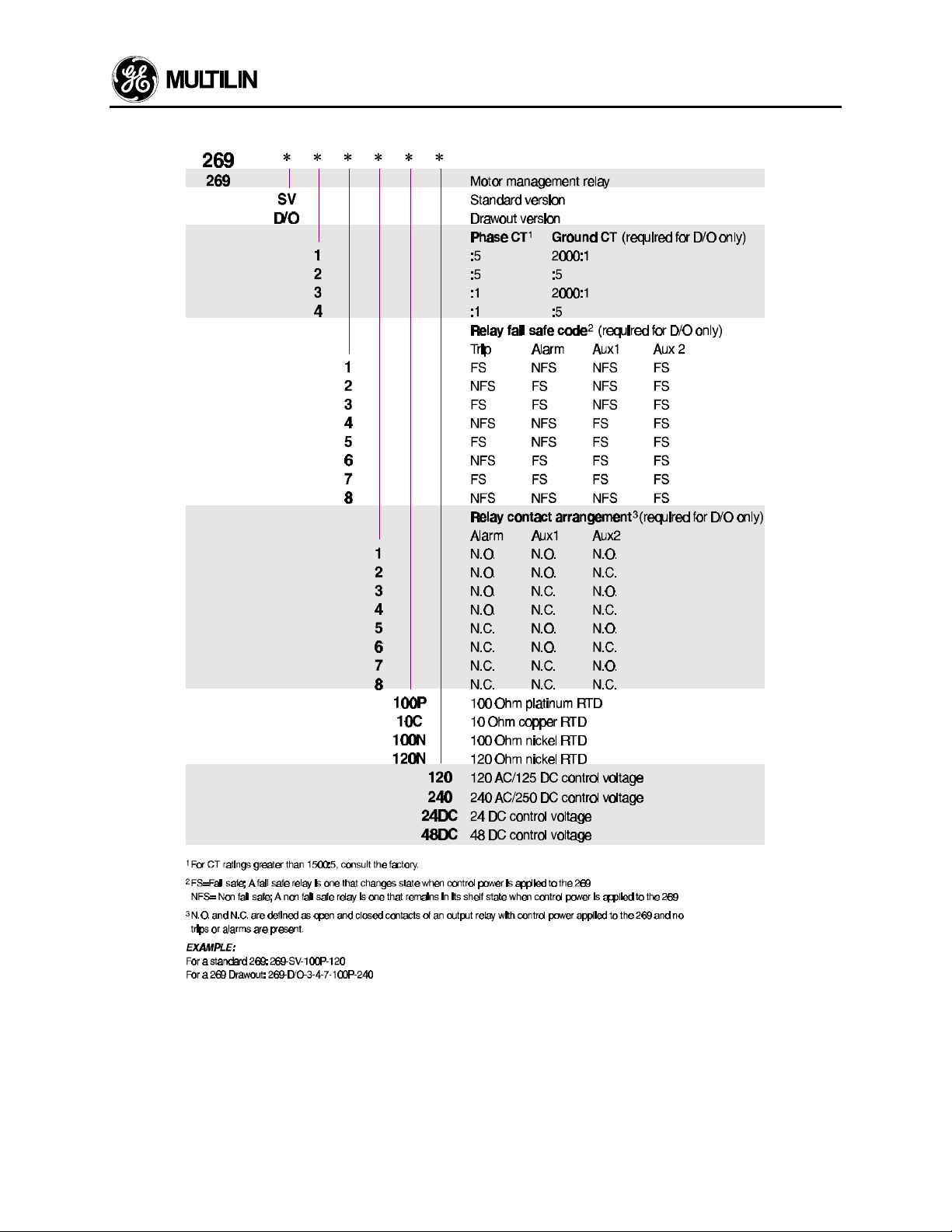
1.4 Order Code/Information
1 INTRODUCTION
The model 269 relay is almost entirely field programmable. The information shown above must be specified when the relay is ordered, as these options are not
selectable in the field. Additional features can be made
available on special order by contacting the GE Multilin
factory.
** See Glossary for definitions
* CT information, failsafe code, and contact ar-
rangement must be specified for drawout relays
only; on standard 269's these features are field
selectable.
1-3
Page 7

1 INTRODUCTION
1.5 Technical Specifications
Phase Current Inputs
conversion: calibrated RMS, sample time 2ms
range: 0.05 to 12 × phase CT primary amps set-
point
full scale: 12 × phase CT primary amps setpoint
accuracy: ± 0.5% of full scale
(0.05 to 2 × phase CT primary amps set-
point)
± 1.0% of full scale
(over 2 × phase CT primary amps set-
point)
Frequency: 20–400 Hz
Ground Fault Current Input
conversion: calibrated RMS, sample time 2ms
range: 0.1 to 1.0 × G/F CT primary amps set-
point (5 Amp secondary CT)
1.0 to 10.0 amps 50:0.025A (2000:1 ratio)
full scale: 1 × G/F CT primary amps setpoint
(5 Amp secondary CT)
10 amps (2000:1 CT)
accuracy: ± 4% of G/F CT primary amps setpoint
(5 Amp secondary CT)
± 0.3 amps primary (2000:1 CT)
Frequency: 20–400 Hz
Overload Curves
curves: 8 curves fixed shape
trip time accuracy: ± 1 sec. up to 13 sec.
± 8% of trip time over 13 sec.
detection level: ± 1% of primary CT amps
Unbalance
display accuracy:± 2 percentage points of true negative
sequence unbalance (In/Ip)
Running Hours Counter
accuracy: ± 1%
Relay Lock-out Time
accuracy: ± 1 minute with control power applied
± 20% of total lock-out time with no con-
trol power applied
Trip/Alarm Delay Times
accuracy: ± 0.5 sec. or 2% of total time, whichever
is greater with the exception of:
1. "INST."setpoints: 20–45ms
2. Ground Fault 0.5 Second delay: +/150 msec.
3. Ground Fault 250 msec delay: +75
msec, -150 msec.
4. Metering setpoints (Page 7): +/- 1.5sec
or 2% of total time
RTD Inputs
sensor types: 10 OHM copper
100 OHM nickel
120 OHM nickel
100 OHM platinum
(specified with order)
display accuracy: ± 2 C
trip/alarm setpoint range: 0-200 °C
dead band: 3 C
maximum lead resistance:25% of RTD 0 °C resistance
Analog Current Output (4-20 mA standard)
PROGRAMMABLE
OUTPUT 0-1 mA 0-20 mA 4-20 mA
MAX LOAD
2000 Ω 300 Ω 300 Ω
MAX OUTPUT 1.01 mA 20.2 mA 20.2 mA
accuracy: ± 1% of full scale reading
polarity: terminal 58 ("-") must be at
ground potential (i.e. output is
not isolated)
Isolation: non-isolated, active source
Update Time: 250 ms max.
Communications
Type: RS485 2-wire, half duplex, isolated
Baud Rate: 300, 1200, 2400
Protocol: Subset of Modbus® RTU
Functions: Read/write setpoints (03/16),
Read actual values (03/04)
Relay Contacts
VOLTAGE
30 VDC 10 30 10
RESISTIVE 125 VDC 10 30 0.5
250 VDC 10 30 0.3
30 VDC 10 30 5
INDUCTIVE 125 VDC 10 30 0.25
(L/R=7ms) 250 VDC 10 30 0.15
RESISTIVE 120 VAC 10 30 10
250 VAC 10 30 10
INDUCTIVE 120 VAC 10 30 4
PF=0.4 250 VAC 10 30 3
CONFIGURATION FORM C NO/NC
CONTACT MATERIAL SILVER ALLOY
MINIMUM PERMISSIBLE LOAD 5 VDC, 100 mA
MAKE/CARRY
CONTINUOUS
MAKE/CARRY
0.2 sec
12 VAC, 100 mA
BREAK
Switch Inputs
Type: dry contacts
Differential Relay Input
relay response time: 100 msec. maximum (contact
closure to output relay activation)
1-4
Page 8

1 INTRODUCTION
CT Burden Due to Connection of 269 Relay
CT INPUT BURDEN
(AMPS) (VA)
1 0.04 43
PHASE CT 4 0.5 31
(1A) 13 4.8 28
5 0.06 2.4
PHASE CT 20 1 2.5
(5A) 65 8.5 2.01
G/F CT 5 0.08 3
(5A) 10 0.3 3
G/F CT 0.025 0.435
(50:0.025) 0.1 3.29
0.5 50
CT Thermal Withstand
Phase CT & G/F 5 amp tap:3 × - continuous
6 × - 40 sec
12 × - 3 sec
G/F 50:0.025 mA 6 × - continuous
Control Power (Includes Tolerances)
frequency: 50/60 Hz
24 VDC, range: 20-30 VDC
48 VDC, range: 30-55 VDC
120 VAC/125 VDC, range: 80-150 VAC/VDC
240 VAC/250 VDC, range: 160-300 VAC/VDC
max. power consumption: 20 VA
Voltage low ride-through time:
100ms (@ 120VAC/125VDC)
NOTE:Relay can be powered from either AC or DC
source. If Control Power input exceeds 250 V,
an external 3A fuse must be used rated to the
required voltage.
Fuse Specifications
T3.15A H 250V
Timelag high breaking capacity
Dielectric Strength
2200 VAC, 50/60 Hz for 1 sec.
GROUND (Terminal 42) to
Output Contacts (Terminals 29 through 40)
Control Power (Terminals 41 & 43)
Current Transformer Inputs (Terminals 72
through 83)
NOTE: If Hi-Pot tests are performed, jumper J201
beside terminal 43 should be placed in the "HIPOT" position. Upon completion of Hi-Pot tests, the
jumper should be placed in the "GND" position.
See Fig. 4.3.
(mΩ)
696 Ω
329 Ω
200 Ω
Type Tests
Dielectric Strength: 2.0 kV for 1 minute to relays,
CTs, power supply
Insulation Resistance:IEC255-5,500Vdc
Transients: ANSI C37.90.1 Oscillatory 2.5kV/1MHz
ANSI C37.90.1 Fast Rise 5kV/10ns
Ontario Hydro A-28M-82
IEC255-4 Impulse/High
Frequency Disturbance
Class III Level
Impulse Test: IEC 255-5 0.5 Joule 5kV
RFI: 50 MHz/15W Transmitter
EMI: C37.90.2 Electromagnetic Interference
@ 150 MHz and 450 MHz, 10V/m
Static: IEC 801-2 Static Discharge
Humidity: 95% non- condensing
Temperature: -25°C to +60°C ambient
Environment: IEC 68-2-38 Temperature/Humidity
Cycle
Dust/Moisture: NEMA 12/IP53
Ambient Temperature and Storage Temperature
-25°C to +60°C
Packaging
Shipping box: 11.40" x 7.50" x 16.00" (WxHxD)
290mm x 190mm x 410mm (WxHxD)
Ship weight: 3.5 kg
7.75 lb.
269 Plus drawout:
Shipping box: 13.25" x 12.50" x 20.50" (LxHxD)
340mm x 320mm x 520mm
Ship weight: 12 kg
26.4 lb.
Certifications
ISO: Manufactured to an ISO9001 certified program
UL: UL recognized under E83849
CSA: Approved under LR41286
CE: Conforms to IEC 947-1, IEC 1010-1
Overvoltage Category: II
Pollution Degree: 2
IP Code: 40X
Note: 269 Drawout does not meet CE compliance.
WARNING:HAZARD may result if the product is
not used for intended purposes.
This equipment can only be serviced
by trained personnel.
1-5
Page 9

1 INTRODUCTION
MPM OPTION SPECIFICATIONS
PHASE CURRENT INPUTS
Conversion: true rms, 64 samples/cycle
CT input: 1A & 5A secondary
Burden: 0.2 VA
Overload: 20xCT for 1s, 100xCT for 0.2s
Range: 1-150% of CT pri
Frequency: up to 32nd harmonic
Accuracy: ± 1% of display
VOLTAGE INPUTS
Conversion: true rms, 64 samples/cycle
VT pri/Sec: direct or 120-72000:69-240
Input range: 20-600 VAC
Full scale: 150/600 VAC autoscaled
Frequency: up to 32nd harmonic
Accuracy: ± 1% of display
ANALOG OUTPUTS
MAX LOAD
MAX OUTPUT 1.1 mA 21 mA
0-1 mA (T1 Option) 4-20 mA (T20 Option)
2400 Ω 600 Ω
Accuracy: ±2% of full scale reading
Isolation: 50V isolated, active source
MEASURED VALUES
OUTPUT
EMI: C37.90.2 Electromagnetic Inter-
ference @ 150 MHz and 450
MHz, 10V/m
Static: IEC 801-2 Static Discharge
Humidity: 95% non-condensing
Temperature: -10°C to +60°C ambient
Environment: IEC 68-2-38 Tempera-
ture/Humidity Cycle
Dust/moisture: NEMA 12/IP53
PACKAGING
Shipping box: 8½" × 6" × 6" (L×H×D) 215cm ×
152cm × 152 cm (L×H×D)
Ship weight: 5 lbs/2.3 kg
CERTIFICATION
ISO: Manufactured to an ISO9001 certified
program
UL: Recognized under E83849
CSA: Recognized under LR41286
Note: It is recommended that all relays be powered
up at least once per year to avoid deterioration of
electrolytic capacitors in the power supply.
Due to updating technology, specifications may be improved without notice.
PARAMETER ACCURACY (%
OF FULL SCALE)
VOLTAGE ±0.2% 20% TO 100% OF VT
kW ±0.4% 0-999,999.99 kW
kVar ±0.4% 0-999,999.99 kVar
kVA ±0.4% 0-999,999.99 kVA
kWh ±0.4% 0-999,999,999 kWh
PF ±1.0% ±0.00-1.00
FREQUENCY ±0.02Hz 20.00-70.00 Hz
RANGE
CONTROL POWER
Input: 90 – 300 VDC or
70 – 265 VAC, 50/60 Hz
Power: nominal 10VA
maximum 20VA
Holdup: 100 ms typical (@ 120 VAC/125
VDC)
TYPE TESTS
Dielectric strength: 2.0 kV for 1 minute to relays,
CTs, VTs, power supply
Insulation resistance: IEC255-5,500Vdc
Transients: ANSI C37.90.1 Oscillatory
2.5kV/1MHz
ANSI C37.90.1 Fast Rise
5kV/10ns
Ontario Hydro A-28M-82
IEC255-4 Impulse/High
Frequency Disturbance
Class III Level
Impulse test: IEC 255-5 0.5 Joule 5kV
RFI: 50 MHz/15W Transmitter
1-6
Page 10
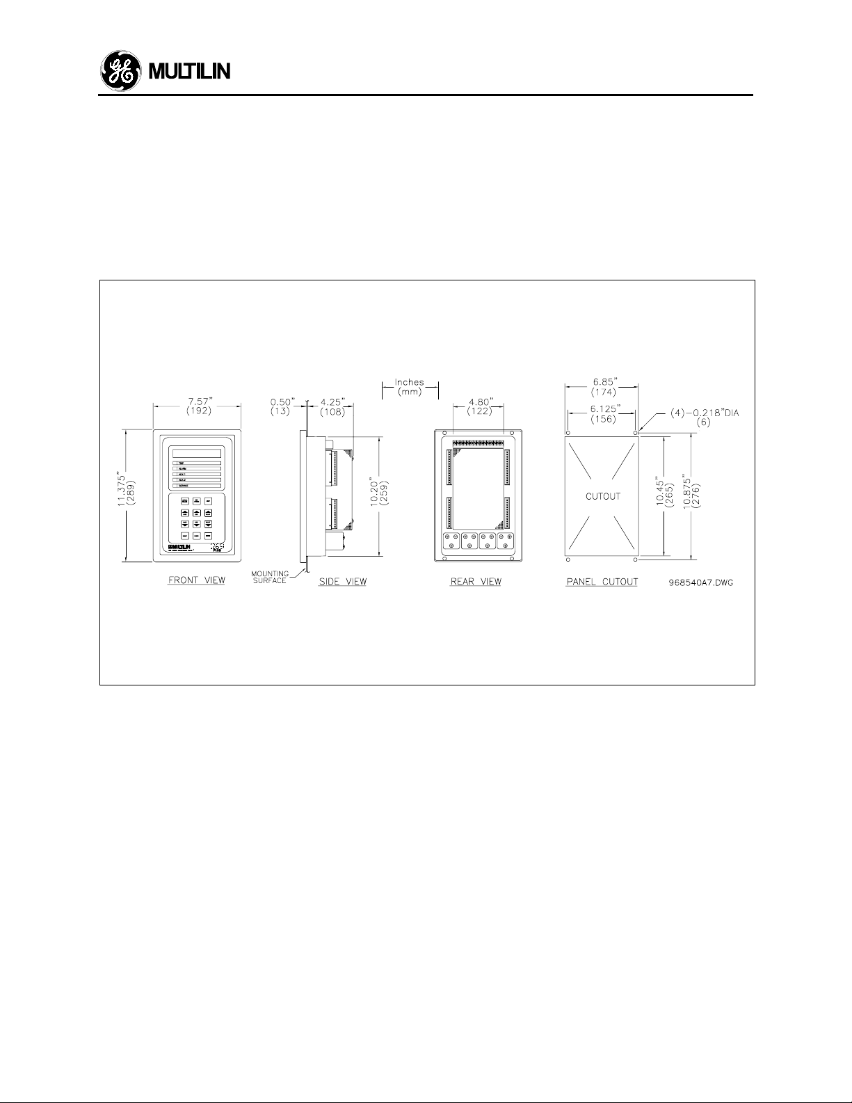
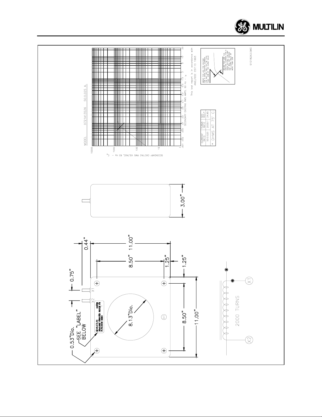
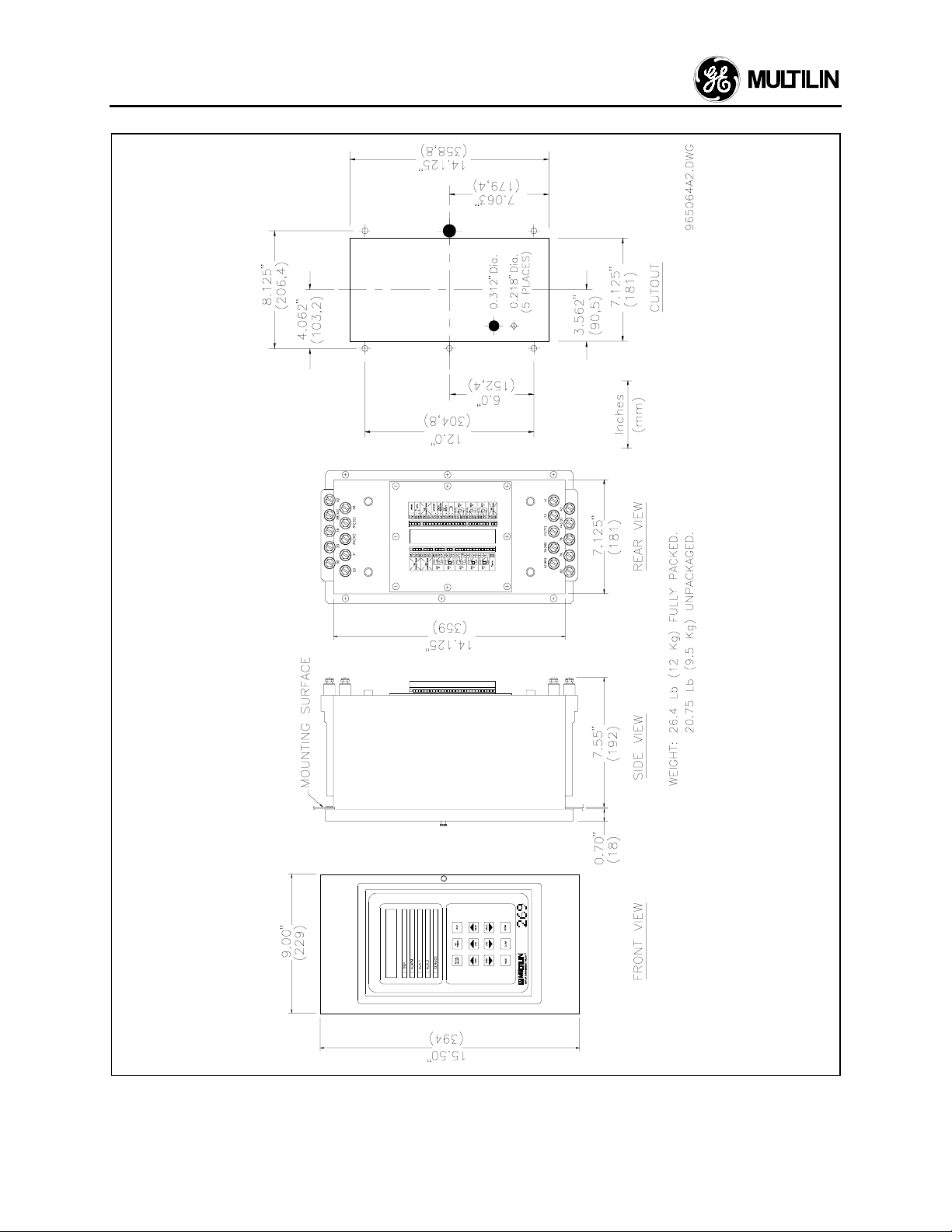
2.1 Physical Dimensions
2 INSTALLATION
The 269 relay is contained in a compact plastic and
metal housing with the keypad, display, and all
indicators located on the front panel. The physical
dimensions of the 269 unit are given in Figure 2.1.
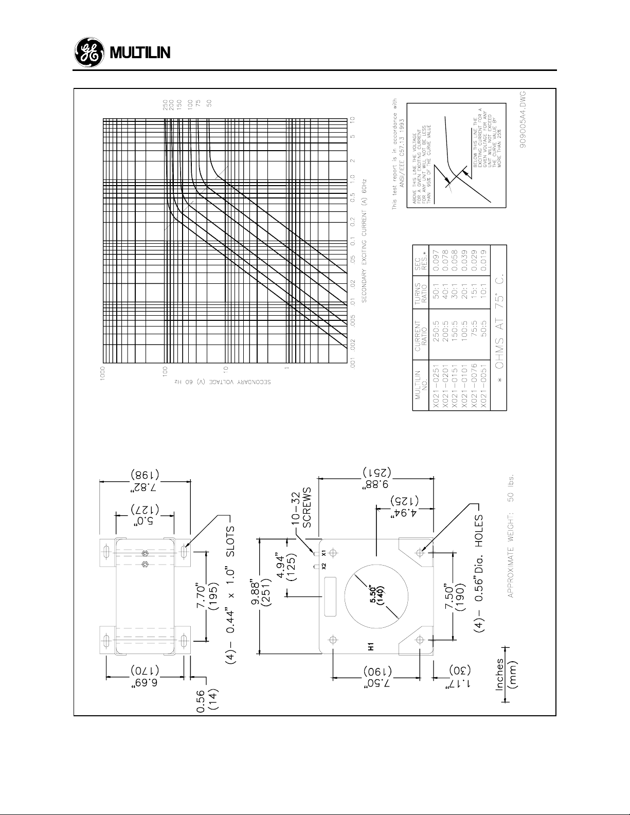
GE Multilin also provides phase and ground fault CTs
if required. Dimensions for these are shown in Figure
2.2a, Figure 2.2b, Figure 2.2c, and Figure 2.2d.
Dimensions of a are for 100:5 to 1000:5 phase CT's;
for the dimensions of 50:5 and 75:5 CT's, consult
factory.
Note
:
Figure 2.1
Physical Dimensions
2-1
Page 11
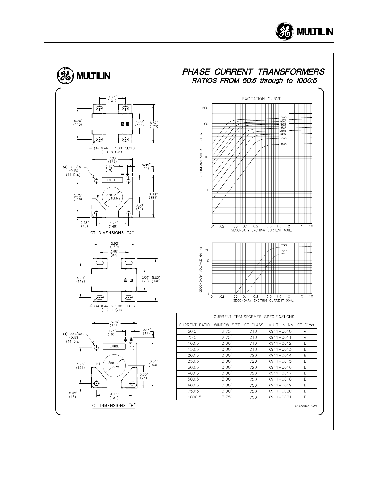
2 INSTALLATION
2-2
Figure 2.2a
Phase CT Dimensions
Page 12
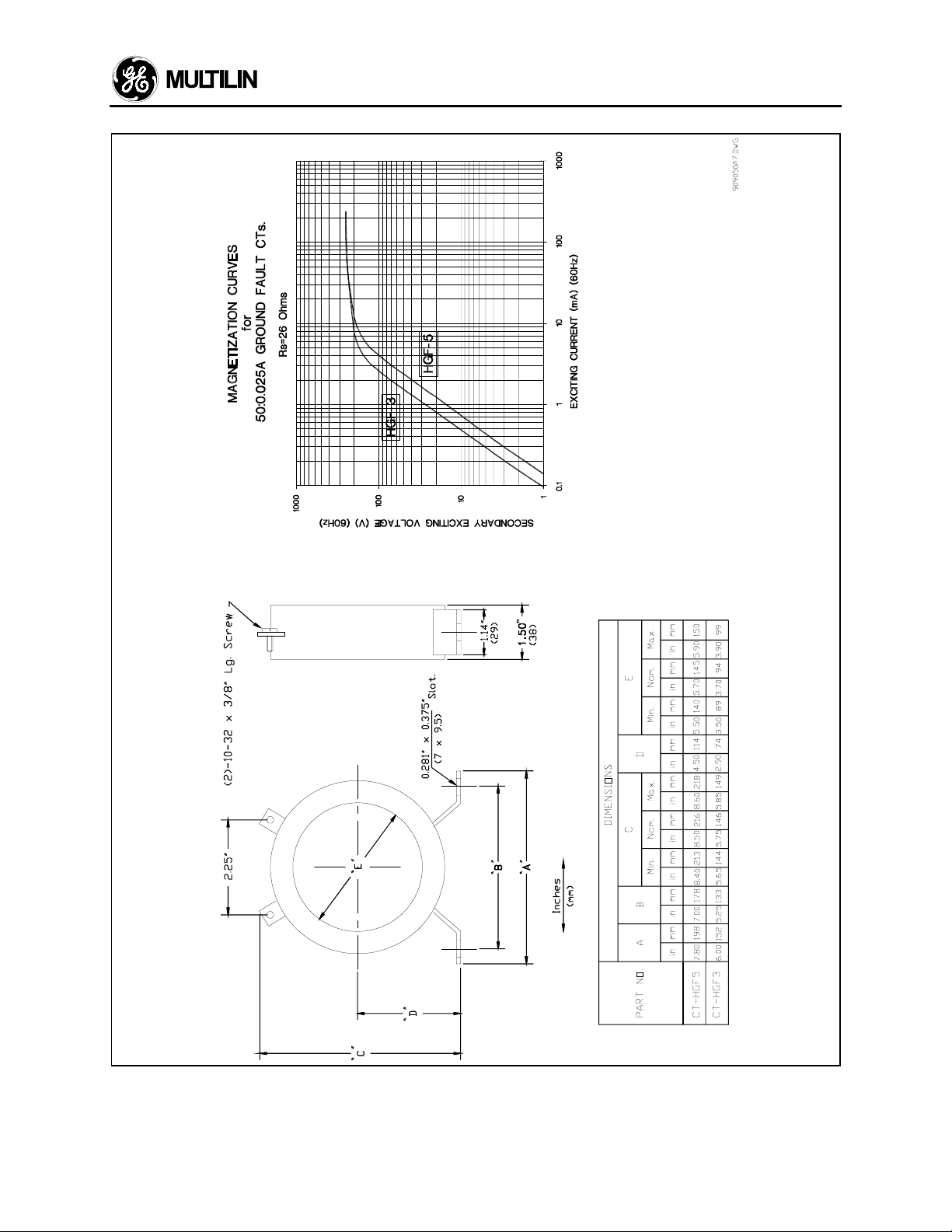
2 INSTALLATION
Figure 2.2b
Ground CT (50:0.025) 3” and 5” window
2-3
Page 13
2 INSTALLATION
2-4
Figure 2.2c
Ground CT (50:0.025) 8” window
Page 14
2 INSTALLATION
Figure 2.2d
Ground CT (x:5) Dimensions
2-5
Page 15
2 INSTALLATION
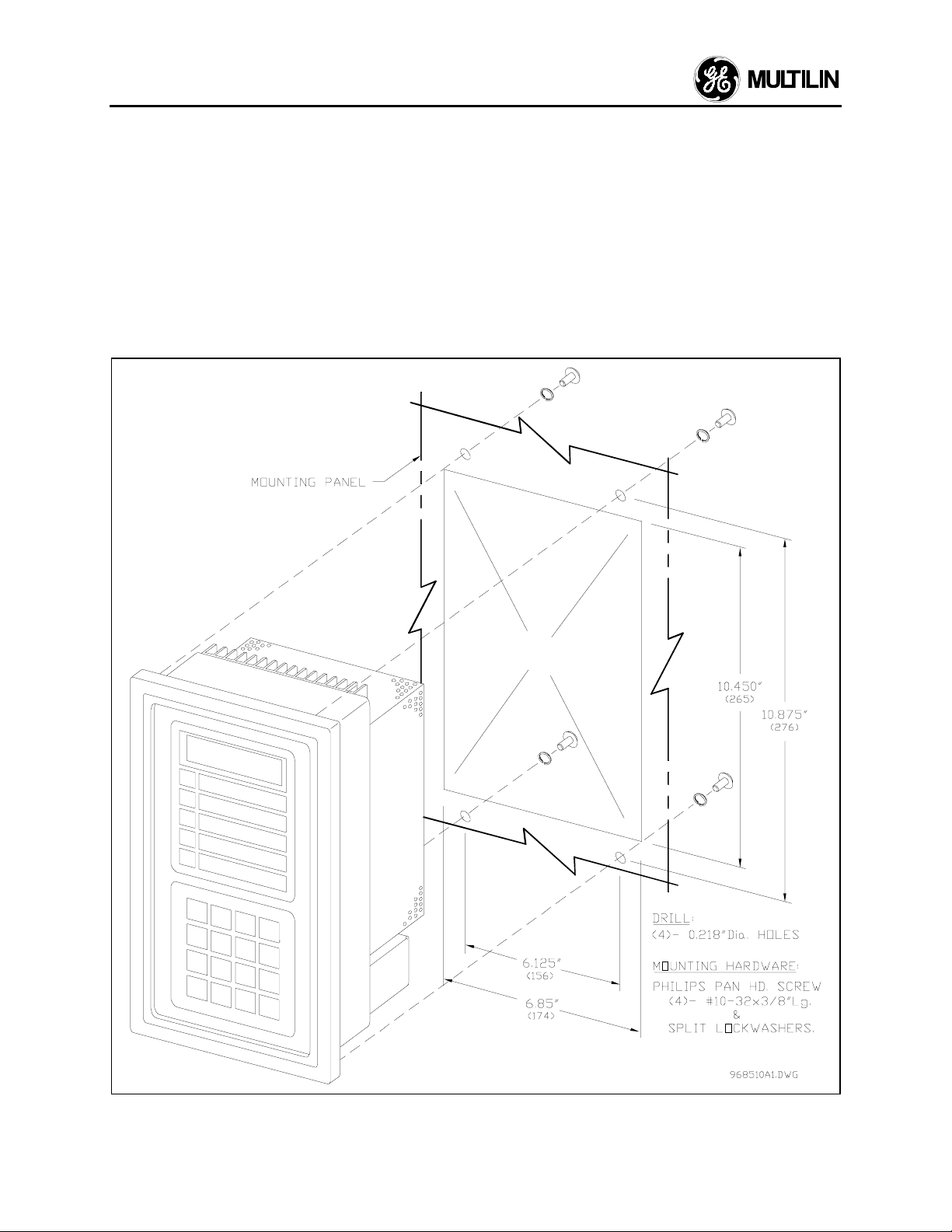
2.2 Mounting
The 269 should be positioned so that the display is
visible and the front panel keypad is accessible. A
cut-out is made in the mounting panel and the unit is
mounted as shown in Figure 2.3. Four washers and
10-32 × 3/8" mounting screws are provided.
Although the 269 circuitry is internally shielded, to
minimize noise pickup and interference the relay
should be placed away from high current conductors
or sources of strong magnetic fields. Connections to
the relay are made through terminal blocks and CTs
located on the rear of the unit.
2.3 External Connections
The connections made to the 269 relay will vary
depending on the programming of the unit. It is not
necessary to use all of the connections provided; a
minimal configuration would include supply power,
three phase current CT inputs and the Trip relay
contacts wired in series with the contactor control
relay or circuit breaker shunt trip coil. Connections to
these and the other terminals outlined below will be
explained in the following sections.
2-6
Figure 2.3
Relay Mounting
Page 16

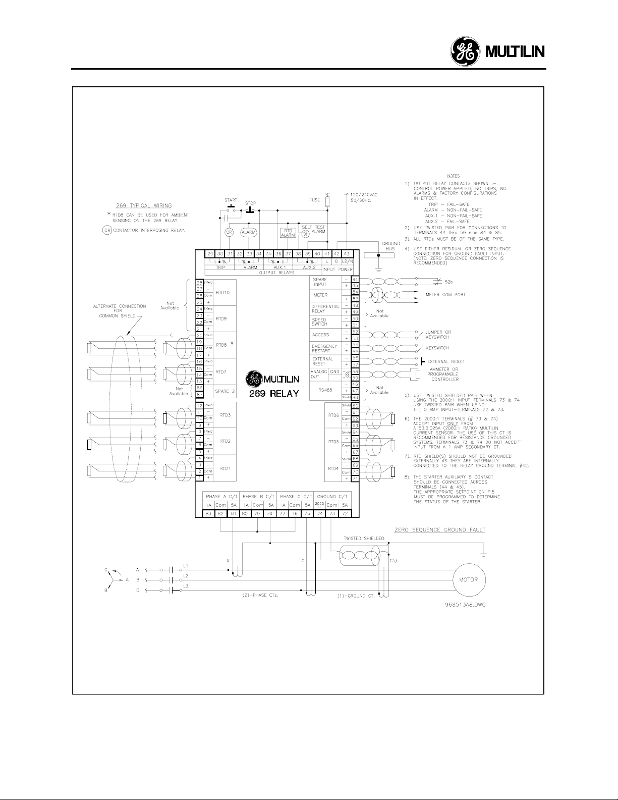
Figure 2.4, Figure 2.6, and Figure 2.7 show typical
connections to the 269 relay.
NOTE: The rear of the 269 relay shows output relay
contacts in their power down state. Figure 2.4, Figure
2.6, and Figure 2.7 show output relay contacts with
power applied, no trips or alarms, Factory
Configurations, i.e. TRIP - fail-safe, ALARM - non-failsafe, AUX.1 - non-fail-safe, AUX.2 - fail-safe). See
Figure 2.5 for a complete list of all possible output
relay contact states. See SETPOINTS page 5 for a
description of the RELAY FAILSAFE CODE.
2 INSTALLATION
Table 2-1
Inputs
-Supply Power L(+), G, N(–) - universal AC/DC
supply
-Phase CTs
-Ground Fault CTs (core balance CT)
-6 Stator RTDs
-2 additional RTDs
-Emergency Restart keyswitch
-External Reset pushbutton
-Programming Access jumper or keyswitch
-Meter Communication Port
Outputs
-4 Sets of Relay Contacts (NO/NC)
-Programmable Analog Current Output Terminals
WARNING: HAZARD may result if the product is
269 External Connections
not used for intended purposes. This
equipment can only be serviced by
trained personnel.
2-7
Page 17

2 INSTALLATION
2-8
Figure 2.4
Relay Wiring Diagram (AC Control Power)
Page 18
2 INSTALLATION
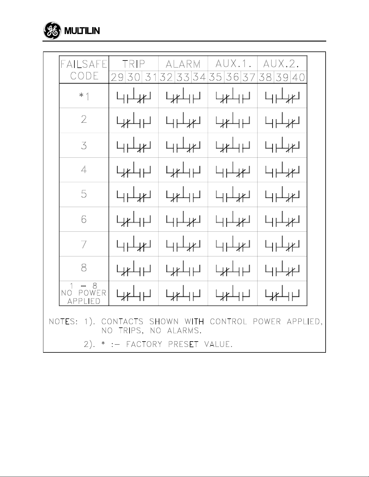
Figure 2.5
WARNING: In locations where system voltage
disturbances cause voltage levels to dip below the
range specified in the Specifications (1.5), any relay
contact programmed failsafe may change state.
Therefore, in any application where the "process" is
more critical than the motor, it is recommended that
the trip relay contacts be programmed non-failsafe. In
this case, it is also recommended that the AUX2
Output Relay Contact States
contacts be monitored for relay failure. If, however,
the motor is more critical than the "process," then the
trip contacts should be programmed failsafe.
2-9
Page 19
2 INSTALLATION
2-10
Figure 2.6
Relay Wiring Diagram (Two Phase CTs)
Page 20
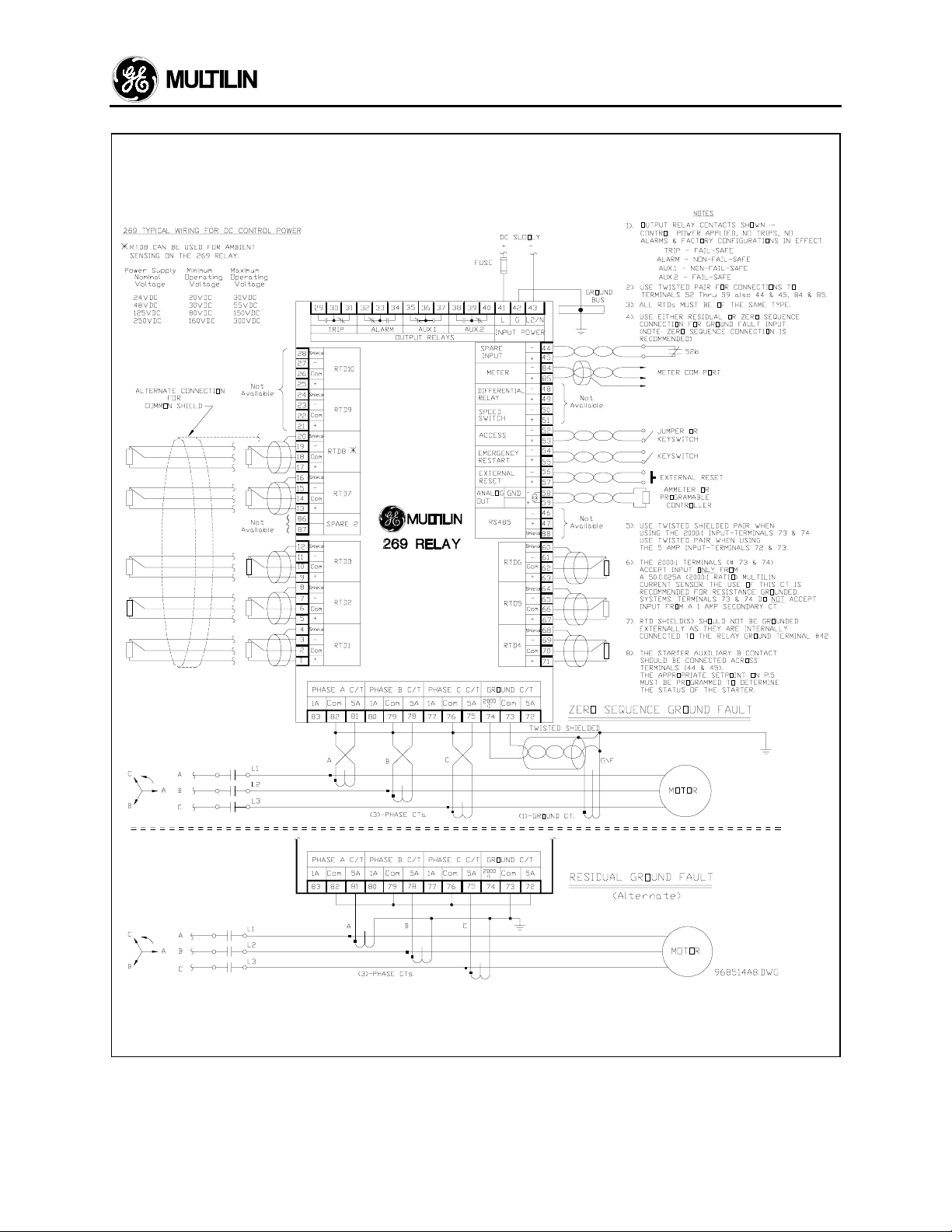
2 INSTALLATION
Figure 2.7
Relay Wiring Diagram (DC Control Power)
2-11
Page 21

2 INSTALLATION
2.4 Control Power
The relay is powered on using any one of four
different switching power supplies: 120-125
VAC/VDC, 240-250 VAC/VDC, 48 VDC, or 24 VDC.
The first two versions have been designed to work
with either AC or DC control power. Maximum power
consumption for the unit is 20 VA.
The 269 will operate properly over a wide range of
supply voltages typically found in industrial
environments (see control power specifications in
section 1.5). When the supply voltage drops below
the minimum, the output relays will return to their
power down states but all setpoints and statistical
data will remain stored in the relay memory. Motor
lock-out time will be adhered to with or without control
power applied. If control power is removed, the relay
keeps track of the Motor Lockout time for up to an
hour.
Control power must be applied to the 269 relay, and
the relay programmed, before the motor is energized.
Power is applied at terminals 41, 42, and 43 which
are terminal blocks having #6 screws.
Note: Chassis ground terminal 42 must be
connected directly to the dedicated cubicle
ground bus to prevent transients from damaging
the 269 resulting from changes in ground
potential within the cubicle. Terminal 42 must be
grounded for both AC and DC units for this
reason.
Verify from the product identification label on the back
of the relay that the control voltage matches the
intended application. Connect the control voltage
input to a stable source of supply for reliable
operation. A 3.15A, slow blow mini fuse (see Fuse
Specifications in Technical Specifications) is
accessible from the back of the 269 by removing the
perforated cover. See Figure 2.8 for details on
replacing the fuse. Using #10 gauge wire or ground
braid, connect terminal 42 to a solid ground which is
typically the copper ground bus in the switchgear.
Extensive filtering and transient protection is built into
the 269 to ensure reliable operation under harsh
industrial operating environments. Transient energy
must be conducted back to the source through filter
ground. The filter ground is separated from the safety
ground terminal 42 at jumper J201 on the back of the
relay to allow dielectric testing of a switchgear with a
269 wired up. Jumper J201 must be removed during
dielectric testing. It must be put back in place once
the dielectric testing is done.
When properly installed, the 269 will meet the
interference immunity requirements of IEC 1000-43/EN61000-4-3; EN 61000-4-6. It also meets the
emission requirements of IEC CISPR11/EN55011
and EN50082-2.
2.5 Phase CT Inputs
One CT for each of the three motor phases is
required to input a current into the relay proportional
to the motor phase current. The phase sequence
must be as shown in Figure 2.4 and Figure 2.7. The
CTs used can have either a 1 amp or 5 amp
secondary and should be chosen so that the motor
full load current is between 75 and 95 percent of the
rated CT primary amps. The CT ratio should thus be
of the form n:1 or n:5 where n is between 20 and
1500. The ratio of the CT used must be programmed
into the 269 (see section 3.7).
The CT connections to the relay are made between
the ":1" and "COM" terminals for 1 amp CTs or
between the ":5" and "COM" terminals for CTs with a
5 amp secondary.
The connections to the 269 internal phase CTs are
made directly via #10 screws.
CTs should be selected to be capable of supplying
the required current to the total secondary load which
includes the 269 relay burden of 0.1 VA at rated
secondary current and the connection wiring burden.
The CT must not saturate under maximum current
conditions which can be up to 8 times motor full load
during starting or up to 20 times during a short circuit.
Only CTs rated for protective relaying should be used
since metering CTs are usually not rated to provide
enough current during faults. Typical CT ratings are:
CSA (Canada): Class10L100 10=accuracy,
L=protection,
100=capacity, higher is
better
ANSI (USA): Class C 100 B4 C or T=protection,
100=capacity, higher is
better, B4=accuracy
IEC (Europe): 20 VA Class 5P20 P=protection,
20VA=capacity, higher is
better
Refer to Appendix H for details on CT withstand, CT
size and saturation, as well as the safe use of 600V
class window type CTs on a 5 kV circuit.
2-12
Page 22
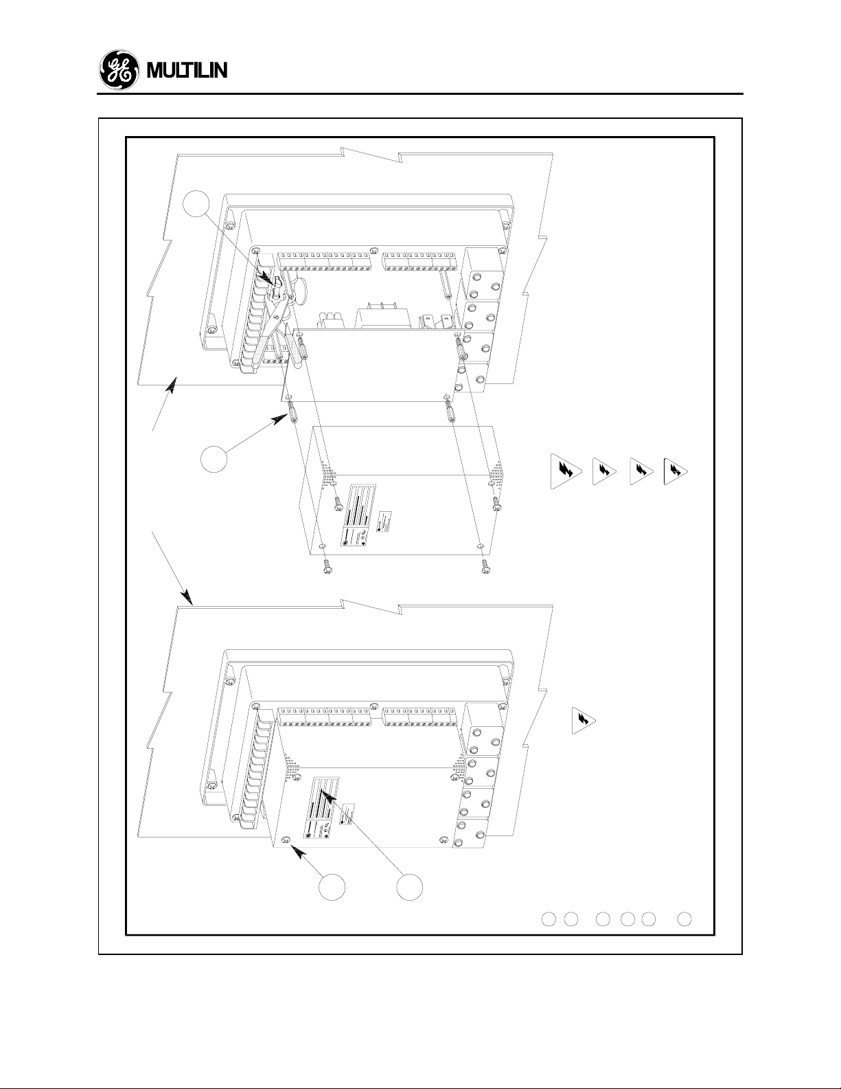
4
3
2 INSTALLATION
NOTES
REMOVE CONTROL POW ER FROM THE RELAY
BEFORE ATTEMPTING TO CHANGE THE FUSE.
WARNING :
CAUTION
CAUTION
ENSURE THAT THE PERFORATED COVER CLEARS ALL COMPONENTS
WHEN BEING RE-INSTALLED.
FOR DRAW OUTS, CONTACT THE FACTORY.
THIS PROCEDURE DOES NOT APPLY TO 269/269Plus DRAWOUT VERSIONS.
CAUTION
AND COMPLETELY PLUG GED IN THE MATING 968023A2.DWG
ENSURE THAT POWER SUPPLY PCB IS FIRM LY IN PLACE
CONNECTOR.
CAUTION
SWITCHGEAR PANEL
CAUTION
1
2
PROCEDURE
REMOVING FUSE:
REPLAC ING FU SE:4IN TECHNICAL SPECIFICATIONS.
USE MINI CARTRIDGE FUSE 3.15A/250V. SEE FUSE SPECIFIC ATIO NS
USING A FUSE PULLER, REMOVE THE FUSE FRO M HO LDER.
REMOVE PER FORATED COVER BY U NSCREW ING THE (4)- #8 -32 SCREW S.
REMOVING PERFOR ATED COVER:
1
REMOVE PO WER SUPPLY BY UNSCREW ING THE (4)- #8 -32 x 3/8" LG. STAND OFFS
& UNPLUGG ING THE INTERBOARD CONN ECTO R.
REMOVING POW ER SUPPLY PCB:
THIS PROCEDURE APPLIES TO 269/269Plus RELAYS
WITH REVISION "C" ONLY.
C = REVISION "C" UNITS.
EXAMPLE: SERIAL N O. C5261392
2
3
POSITION THE FUSE IN THE PULLER AND PLACE BACK IN FUSE HOLDER.
PERFORATED COVER & SCREWS.
RE-INSTALL POWER SUPPLY PCB, STA NDOFFS,
5
6
Figure 2.8
Replacing a blown fuse
2-13
Page 23
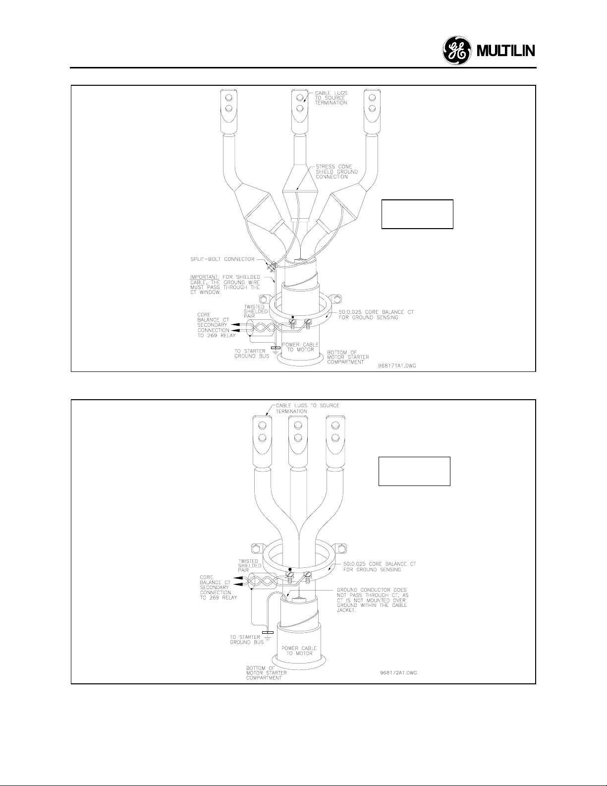
2 INSTALLATION
SHIELDED
CABLE
Figure 2.9a
Core Balance Ground CT Installation using Shielded Cable
UNSHIELDED
CABLE
2-14
Figure 2.9b
Core Balance Ground CT Installation using Unshielded Cable
Page 24

2 INSTALLATION
2.6 Ground CT Input
All current carrying conductors must pass through a
separate ground fault CT in order for the ground fault
function to operate correctly. If the CT is placed over
a shielded cable, capacitive coupling of phase current
into the cable shield during motor starts may be
detected as ground current unless the shield wire is
also passed through the CT window; see Figure 2.9a.
If a safety ground is used it should pass outside the
CT window; see Figure 2.9b.
The connections to the 269 internal ground CT are
made directly via #10 screws. The ground CT is
connected to terminals 73 and 72 for a 5 amp
secondary CTs, or to terminals 73 and 74 for a GE
Multilin 50:0.025A (2000:1 ratio) CTs, as shown in
Figure 2.4, Figure 2.5, and Figure 2.7. The polarity of
the ground CT connection is not important. It is
recommended that the two CT leads be twisted
together to minimize noise pickup. If a 50:0.025A
(2000:1 ratio) ground CT is used, the secondary
output will be a low level signal which allows for
sensitive ground fault detection.
NOTE: The GE Multilin 2000:1 CT is actually a
50:0.025A CT recommended for resistance
grounded systems where sensitive ground fault
detection is required. If higher levels are to be
detected, a 5 Amp secondary CT should be used.
For a solidly grounded system where higher ground
fault currents will flow, a 5 amp secondary CT with a
primary between 20 and 1500 A may be used to
surround all phase conductors. The phase CTs may
also be residually connected to provide ground
sensing levels as low as 10% of the phase CT
primary rating. For example, 100:5 CTs connected in
the residual configuration can sense ground currents
as low as 10 amps (primary) without requiring a
separate ground CT. This saves the expense of an
extra CT, however 3 phase CTs are required. If this
connection is used on a high resistance grounded
system verify that the ground fault alarm and trip
current setpoints are below the maximum ground
current that can flow due to limiting by the system
ground resistance. Sensing levels below 10% of the
phase CT primary rating is not recommended for
reliable operation.
2.7 Trip Relay Contacts
The main control relay or shunt trip coil of the motor
starter or circuit breaker should be connected to the
Trip relay contacts of the 269. These contacts are
available as normally open (NO), normally closed
(NC), and can switch up to 10 amps at either 250
VAC or 30 VDC with a resistive load. Silver cadmium
oxide contacts are used because of their ability to
handle high inrush currents on inductive loads.
Contact GE Multilin if these contacts are to be used
for carrying low currents since they are not
recommended for use below 0.1 amps. Connection to
the motor contactor or breaker is shown in Figure 2.4,
Figure 2.5, and Figure 2.7.
The Trip output relay will remain latched after a trip.
This means that once this relay has been activated it
will remain in the active state until the 269 is manually
reset. The Trip relay contacts may be reset by
pressing the RESET key (see section 3.1) if motor
conditions allow, or by using the Emergency Restart
feature (see section 2.12), or the External Reset
terminals, or by remote communications via the
RS485 port.
The Trip relay may be programmed to be fail-safe or
non-fail-safe. When in the fail-safe mode, relay
activation or a loss of power condition will cause the
relay contacts to go to their power down state. Thus,
in order to cause a trip on loss of power to the 269,
output relays should be programmed as fail-safe.
The Trip relay cannot be reset if a lock-out is in effect.
Lock-out time will be adhered to regardless of
whether control power is present or not. A maximum
of one hour lockout time is observed if control power
is not present.
The Trip relay can be programmed to activate on any
combination of the following trip conditions: overload,
stator RTD overtemperature, rapid trip, unbalance,
ground fault, short circuit, RTD overtemperature,
acceleration time, number of starts per hour, single
phase (see section 3.4 for factory preset
configurations).
Connections to the Trip relay contacts are made via a
terminal block which uses #6 screws.
When the phase CTs are connected residually, the
secondaries must be connected in such a way to
allow the 269 to sense any ground current that might
be flowing. To correctly display ground current and
trip or alarm on ground fault, the connection to the
269 must be made at terminals 72 and 73 as shown
in Figure 2.4 and Figure 2.7. These terminals are
designed to accept input from a 5A secondary CT.
The 269 must also be programmed for a 5A
secondary ground CT with the primary being equal to
the phase CT primary. This is done in SETPOINTS,
page 1.
NOTE: The rear of the 269 relay shows output relay
contacts in their power down state. Figure 2.4, Figure
2.6, and Figure 2.7 show output relay contacts with
power applied, no trips or alarms, and Factory
Configurations in effect (i.e. TRIP - fail-safe, ALARM non-fail-safe, AUX.1 - non-fail-safe, AUX.2 - fail-safe).
See Figure 2.5 for a list of all possible contact states.
WARNING: In locations where system voltage
disturbances cause voltage levels to dip below
the range specified in the Specifications (1.5), any
relay contact programmed failsafe may change
2-15
Page 25

2 INSTALLATION
state. Therefore, in any application where the
"process" is more critical than the motor, it is
recommended that the trip relay contacts be
programmed non-failsafe. In this case, it is also
recommended that the AUX2 contacts be
monitored for relay failure. If, how ever, the motor
is more critical than the "process" then the trip
contacts should be programmed failsafe.
2.8 Alarm Relay Contacts
These contacts are available as normally open (NO),
normally closed (NC), with the same ratings as the
Trip relay but can only be programmed to activate
when alarm setpoint levels are reached. (On a
Drawout version of 269, only one set of alarm
contacts is available and the user must specify
normally open or normally closed and failsafe or nonfailsafe when ordering). Thus these contacts may be
used to signal a low level fault condition prior to motor
shut-down.
Conditions which can be programmed to activate the
relay are alarm levels for the following functions:
immediate overload; mechanical jam; unbalance;
undercurrent; ground fault; stator RTD
overtemperature; RTD overtemperature; broken RTD;
low temperature or shorted RTD; and self-test alarm
(see section 3.4 for factory preset configurations).
The relay can be configured as latched or unlatched
and fail-safe or non-fail-safe.
These contacts may be used for alarm purposes or to
trip devices other than the motor contactor. For
example, the ground fault and short circuit functions
may be directed to Auxiliary relay #1 to trip the main
circuit breaker rather than the motor starter.
Connections to the relay contacts are made via a
terminal block which uses #6 screws.
NOTE: The rear of the 269 relay shows output relay
contacts in their power down state. Figure 2.4, Figure
2.6, and Figure 2.7 show output relay contacts with
power applied, no trips or alarms, and Factory
Configurations in effect (i.e. TRIP - fail-safe, ALARM non-fail-safe, AUX.1 - non-fail-safe, AUX.2 - fail-safe).
See Figure 2.5 for a list of all possible contact states.
2.10 Auxiliary Relay #2 Contacts
This relay provides another set of NO/NC contacts
with the same ratings as the other relays. (On a
Draw-out version of 269, only one set of Aux.2
contacts is available and the user must specify
normally open or normally closed when ordering).
This relay is different from the others in the fact that it
is permanently programmed as latched and fail-safe.
This relay may be programmed to activate on any
combination of alarm conditions (see section 3.4 for
factory preset configurations). The feature
assignment programming is thus the same as for the
Alarm relay.
Connections to the Alarm relay contacts are made via
a terminal block which uses #6 screws.
NOTE: The rear of the 269 relay shows output relay
contacts in their power down state. Figure 2.4, Figure
2.6 and Figure 2.7 show output relay contacts with
power applied, no trips or alarms, and Factory
Configurations in effect (i.e. TRIP - fail-safe, ALARM non-fail-safe, AUX.1 - non-fail-safe, AUX.2 - fail-safe).
See Figure 2.5 for a list of all possible contact states.
2.9 Auxiliary Relay #1 Contacts
Auxiliary relay #1 is provided to give an extra set of
NO/NC contacts which operate independently of the
other relay contacts. (On a Drawout version of 269,
only one set of Aux.1 contacts is available and the
user must specify normally open or normally closed
and failsafe or non-failsafe when ordering). This
auxiliary relay has the same ratings as the Trip relay.
Auxiliary relay #1 can be configured as latched or
unlatched and fail-safe or non-fail-safe. The
conditions that will activate this relay can be any trip
or alarm indications (see section 3.4 for factory preset
configurations).
Connections to the relay contacts are made via a
terminal block which uses #6 screws.
NOTE: The rear of the 269 relay shows output relay
contacts in their power down state. Figure 2.4, Figure
2.6, and Figure 2.7 show output relay contacts with
power applied, no trips or alarms, and Factory
Configurations in effect (i.e. TRIP - fail-safe, ALARM non-fail-safe, AUX.1 - non-fail-safe, AUX.2 - fail-safe).
See Figure 2.5 for a list of all possible contact states.
2-16
Page 26
2 INSTALLATION
Figure 2.10
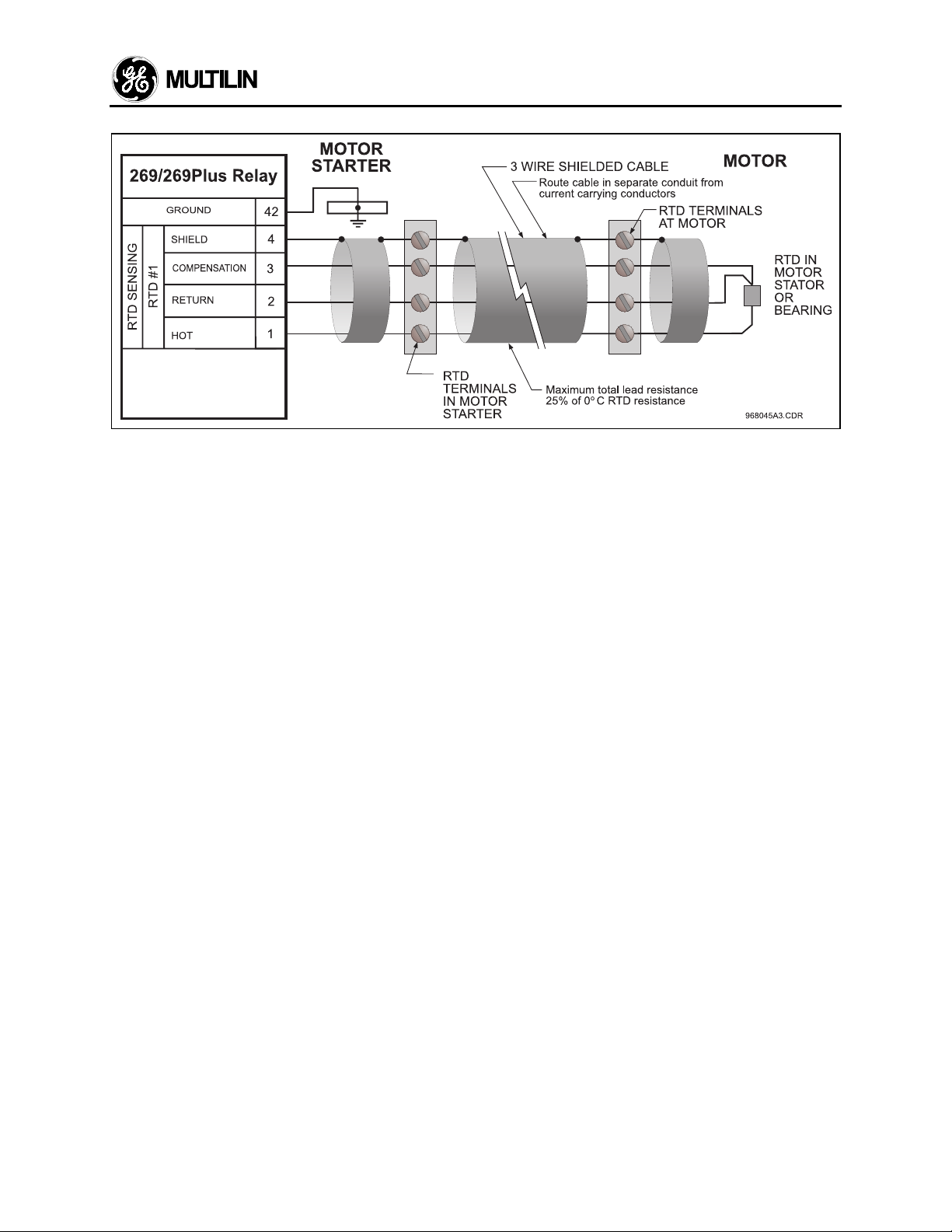
2.11 RTD Sensor Connections
Up to six resistance temperature detectors (RTDs)
may be used for motor stator temperature monitoring.
The remaining RTD inputs may be used for motor
and load bearing, or other temperature monitoring
functions. All RTDs must be of the same type. RTD
#8 may be used to monitor ambient air temperature.
This is done to enhance protection in environments
where the ambient temperature varies considerably.
The number of stator RTDs used together with RTD
trip and alarm temperatures must be programmed
into the 269 (see sections 3.16, 3.17). The RTD type
to be used must be specified when ordering the 269
relay. If the type of RTD in use is to be changed, the
269 must be returned to the factory.
Each RTD has four connections to the 269 relay as
shown in Figure 2.4, Figure 2.6, and Figure 2.7.
Since the RTD indicates temperature by the value of
its resistance, it is necessary to compensate for the
resistance of the connecting wires, which is
dependent on lead length and ambient temperature.
The 269 uses a circuit to cancel this resistance and
reads only the actual RTD resistance. Correct
operation will occur providing all three wires are of the
same length and the resistance of each lead is not
greater than 25% of the RTD 0°C resistance. This
can be accomplished by using identical lengths of the
same type of wire. If 10 ohm copper RTDs are to be
used, special care should be taken to keep the lead
resistance as low as possible.
If RTD #8 is to be used for ambient air temperature
measurement, the RTD should be placed and
mounted somewhere in the motor cooling air intake
flow. The sensor should be in direct contact with the
cooling air but not with any surface that is at a
temperature other than the cooling air. This RTD is
RTD Wiring
selected for ambient temperature use in page 5 of
SETPOINTS mode.
If no RTD sensor is to be connected to any of the
RTD terminals on the 269, the terminals may be left
open.
If fewer than 6 stator RTDs are to be employed, they
should be connected to the lowest numbered relay
RTD connections. For example, if 3 stator RTDs are
to be used they should be connected to the terminals
for RTD1, RTD2, and RTD3 (terminals #1-12). Other
RTDs should be connected to the terminals for RTD7RTD10 (terminals #13-28) as shown in Figure 2.4.
The connections are made via terminal blocks which
can accommodate up to #16 AWG multi-strand wire.
Note: Shielded, three-wire cable must be used in
industrial environments to prevent noise pickup.
Wherever possible, the RTD leads should be kept
close to grounded metal casings and avoid areas
of high electromagnetic or radio frequency fields.
RTD leads should not run adjacent to, or in the
same conduit as high current carrying wires. It is
recommended to use a three wire shielded cable
of #18 AWG copper conductors. The shield
connection of the RTD should not be grounded at
the sensor end as there is an internal ground on
the 269. This arrangement prevents noise pickup
that would otherwise occur from circulating
currents due to differences in ground potentials
on a doubly grounded shield.
2-17
Page 27

2 INSTALLATION
2.12 Emergency Restart Terminals
If it is desired to override relay trips or lock-outs and
restart the motor, a normally open keyswitch should
be installed between terminals 54 and 55.
Momentarily shorting these terminals together will
cause the thermal memory of the 269 to discharge to
0% (if RTD input to thermal memory is enabled,
thermal memory can be reduced to 0% by keeping
terminals 54 and 55 shorted together for more than
11 seconds; see section 3.20). The Emergency
Restart terminals can thus be used to override an
OVERLOAD TRIP. Shorting the Emergency Restart
terminals together will also decrement the relay's
internal starts/hour counter by 1 and therefore allow
the operator to override a STARTS/HOUR inhibit or
time between starts inhibit.
Note: This option should be used only when an
immediate restart after a lock-out trip is required for
process integrity or personnel safety. Discharging
the thermal memory of the 269 gives the relay an
unrealistic value for the thermal capacity remaining in
the motor and it is possible to thermally damage the
motor by restarting it. Thus, complete protection may
be compromised in order to restart the motor using
this feature.
A twisted pair of wires should be used. Connection to
the 269 is made via a terminal block which can
accommodate up to #16 AWG multi-strand wire.
2.13 External Reset Terminals
An external reset switch, which operates similarly to
the keypad RESET key (see section 3.1), can be
connected to terminals 56 and 57 for remote reset
operation. The switch should have normally open
contacts. Upon closure of these contacts the relay
will be reset. This external reset is equivalent to
pressing the keypad RESET key. Keeping the
External Reset terminals shorted together will cause
the 269 to be reset automatically whenever motor
conditions allow.
A twisted pair of wires should be used. Connection to
the 269 is made via a terminal block which can
accommodate up to #16 AWG multi-strand wire.
2.14 Analog Output Terminals (NonIsolated)
Terminals 58 and 59 of the 269 are available for an
analog current output representing one of:
percentage of motor thermal capacity used; motor
current as a percentage of full load (i.e. 0.25-2.5
XFLC); hottest stator RTD temperature as a
percentage of 200°C; RTD#7 (bearing) temperature
as a percentage of 200°C; or CT secondary current
as a percentage of CT secondary amps rating. The
choice of output is selected in page 5 of SETPOINTS
mode. This selection can be made or changed at any
time without affecting the protective features of the
relay.
The output current range is factory default at 4-20
mA. However, this range may be enlarged in page 5
of SETPOINTS mode. 4 mA output corresponds to a
low scale reading (i.e. 0% thermal capacity used,
0.25xFLC, 0
RTD#7 temperature, or 0 A phase CT secondary
current). 20 mA output current corresponds to a high
scale reading (i.e. 100% thermal capacity used,
2.5xFLC or lower phase current, 200
stator RTD and RTD#7 temperature, or either 1 A or
5 A phase CT secondary depending on the CT used).
This output is an active, non isolated current source
suitable for connection to a remote meter, chart
recorder, programmable controller, or computer load.
Current levels are not affected by the total lead and
load resistance as long as it does not exceed 300
ohms for the 4-20 mA or the 0-20 mA range (2000
ohms for 0-1 mA range). For readings greater than
100% of full scale the output will saturate at 20.2 mA.
This analog output is not isolated. Terminal 58 is
internally connected to system ground. Consequently
the negative terminal of the connected load device
must be at ground potential. When isolation is
necessary, an external two-wire isolated transmitter
should be used between the 269 and the load (e.g.
PLC).
A twisted pair of wires should be used. Connection to
the 269 is made via a terminal block which can
accommodate up to #16 AWG multi-strand wire.
o
C hottest stator RTD temperature,
o
C for hottest
2.15 Programming Access Terminals
When a jumper wire is connected between ACCESS
terminals 52 and 53 all setpoints and configurations
can be programmed using the keypad. Once
programming is complete the jumper will normally be
removed from these terminals. When this is done all
actual and setpoint values can still be accessed for
viewing; however, if an attempt is made to store a
new setpoint value the message "ILLEGAL ACCESS"
will appear on the display and the previous setpoint
will remain intact. In this way all of the programmed
setpoints will remain secure and tamperproof.
Alternatively, these terminals can be wired to an
external keyswitch to permit setpoint programming
upon closure of the switch. For additional tamper
proof protection, a software access code may be
programmed on Page 6 of SETPOINTS. See section
3 (Setup and Use).
2-18
Page 28

A twisted pair of wires should be used for connection
to an external switch. Connection to the 269 is made
via a terminal block which can accommodate up to
#16 AWG multi-strand wire.
2.16 Display Adjustment
Once the 269 relay has been installed and input
power applied, the contrast of the LCD display may
have to be adjusted. This adjustment has been made
at the factory for average lighting conditions and a
standard viewing angle but can be changed to
optimize the display readability in different
environments. To alter the display contrast the
trimpot on the rear of the unit marked "CONTRAST"
must be adjusted with a small slotted screwdriver.
2 INSTALLATION
thin panels, the relay will not seat properly and the
door will not shut over the relay when installed on a
thick panel. Loosening the screws and moving the
relay forward before retightening will fix the problem.
RELAY REMOVAL - Open the hinged door. Next
remove the two ten finger connecting plugs making
sure the top one is removed first. Swivel the cradleto-case hinged levers at each end of the 269 cradle
assembly and slide the assembly out of the case.
RELAY INSTALLATION - Slide the 269 cradle
assembly completely into the case. Swivel the hinged
levers in to lock the 269 cradle assembly into the
drawout case. Install the two ten finger connecting
plugs making sure the bottom plug is installed first.
Close the hinged door and secure with the captive
screw.
2.17 Front Panel Faceplate
The front panel faceplate is composed of a
polycarbonate material that can be cleaned with
isopropyl or denatured alcohol, freon, naphtha, or
mild soap and water.
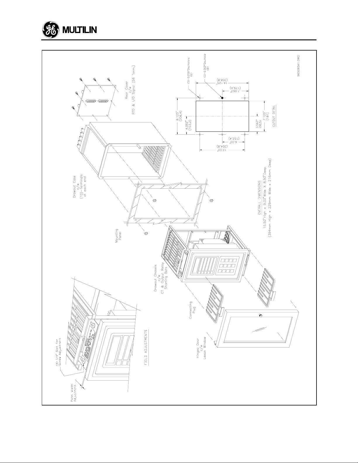
2.18 269 Drawout Relay
The model 269 relay is available in a drawout case
option. The operation of the relay is the same as
described elsewhere in this manual except for the
differences noted in this section. The physical
dimensions of the drawout relay are as shown in
Figure 2.11. The relay should be mounted as shown
in Figure 2.12.
The drawout 269 relay can be removed from service
without causing motor shut-down. This can be useful
for replacing, calibrating, or testing units.
RELAY MOUNTING - Make cutout as shown and drill
six 7/32" holes on mounting panel. Approximately 21/2" should be clear at the top and bottom of the
cutout in the panel for the hinged door. Ensure that
the five #6-32 nuts are removed from the threaded
studs in the mounting flange and that the drawout
chassis has been removed from the drawout case.
Install the case from the rear of the mounting panel
by aligning the five #6-32 threaded case studs to the
previously drilled holes. With the studs protruding
through the holes secure the case on the right hand
side with two #6-32 nuts provided. Install the hinged
door on the front of the mounting panel using three
#6-32 nuts provided.
NOTE: There must be at least ½" clearance on the
hinged side of the drawout relay to allow the door
to open.
IMPORTANT NOTE
relay cradle assembly the top ten finger connecting
plug must be withdrawn first. This isolates the 269
output relay contacts before power is removed from
the relay. When installing the drawout relay cradle
assembly the bottom ten finger connecting plug must
be installed first. This causes power to be applied to
the 269 relay before the output relay contacts are
placed in the circuit.
After a 269 relay cradle assembly has been removed
from the drawout case it is recommended that the
hinged door be closed in order to reduce the risk of
electric shock.
Due to the hardware configuration of the drawout
relay shorting bars, the RELAY FAILSAFE CODE
(SETPOINTS, page 5) should not be changed without
consulting the factory. Spare shorting bars are
included with each drawout specifically for the
required modification. Wiring for the 269 drawout is
shown in Figure 2.13. If it is required that any of the
output relay configurations in Figure 2.13 be different
than shown, this information must be stated when the
relay is ordered.
The 269 Drawout does not meet the IEC947-1 and
IEC1010-1.
No special ventilation requirements need to be
observed during the installation of this unit
: When removing the drawout
.
FIELD ADJUSTMENTS - There are four screws
holding the plastic 269 case to the drawout cradle.
These screw into holes which are slotted to
compensate for panel thickness. If the 269 case is
mounted at the extreme end of the slot intended for
2-19
Page 29
2 INSTALLATION
2-20
Figure 2.11
269 Drawout Relay Physical Dimensions
Page 30
2 INSTALLATION
Figure 2.12
269 Drawout Relay Mounting
2-21
Page 31

2 INSTALLATION
2-22
Figure 2.13
269 Drawout Relay Typical Wiring Diagram
Page 32

2 INSTALLATION
2.19 Meter Option Installation
The addition of a GE Multilin MPM (Motor Protection
Meter) option allows the 269 user to monitor and
assign protective features based on voltage and
power measurement. Either meter also provides four
isolated analog outputs representing: Current, Watts,
Vars, and Power Factor. These outputs from the
meter can provide the signals for the control of the
motor or a process.
MPM External Connections
Physical dimensions for the MPM and the required
cutout dimensions are shown in Figure 2.16. Once
the cutout and mounting holes are made in the panel,
use the eight #6 self tapping screws to secure the
relay.
MPM Wiring
Signal wiring is to box terminals that can
accommodate wire as large as 12 gauge. CT, VT and
control power connections are made using #8 screw
ring terminals that can accept wire as large as 8
gauge.
Consult the wiring Figure 2.17 through 2.22 for
suggested wiring. For proper operation of the MPM
and 269 set, MPM control power and phase CTs/VTs
must be connected. Other features may be wired
depending on the MPM model ordered.
Control Power (5/6/7/8)
Control power supplied to the
MPM must match the installed
power supply. If the applied
voltage does not match, damage
to the unit may occur.
A universal AC/DC power supply is standard. It
covers the range 90 - 300 VDC and 70 - 265 VAC
50/60 Hz. It is not necessary to make any adjustment
to the MPM as long as the control voltage falls within
this range. A low voltage power supply is available as
an option. It covers the range 20 - 60 VDC and 20 48 VAC 50/60 Hz. Verify from the product
identification label on the back of the MPM that the
control voltage matches the intended application.
Connect the control voltage input to a stable source
of supply for reliable operation. A 2 amp fuse is
accessible from the back of the MPM by sliding back
the fuse access door. Using #8 gauge wire or ground
braid, connect terminals 5 & 6 to a solid system
ground which is typically a copper bus in the
switchgear. Extensive filtering and transient
protection is built into the MPM to ensure reliable
operation under harsh industrial operating
environments. Transient energy must be conducted
back to the source through filter ground terminal 5.
The filter ground terminal (5) is separated from the
safety ground terminal (6) to allow dielectric testing of
switchgear with a MPM wired up. Connections to the
filter ground terminal must be removed during
dielectric testing.
030
Figure 2.14 Control Power Wiring
When properly installed, the MPM will meet the
interference immunity requirements of IEC 801 and
ANSI C37.90.1.
VT Inputs (1-4)
The MPM can accept input voltages from 0 - 600VAC
between the voltage inputs (V
common (Vn). These inputs can be directly
connected or supplied via external VTs. If voltages
greater than 600VAC are to be measured, external
VTs are required. When measuring line to line
quantities using inputs V
voltage common input Vn is grounded. This input is
used as a reference for measuring the voltage inputs.
, V2, V3) and voltage
1
, V2 and V3, ensure that the
1
All connections to the MPM
voltage inputs should be
connected using HRC fuses with
a 2 AMP rating to ensure
adequate interrupting capacity.
CT Inputs (9-20)
5 amp or 1 amp current transformer secondaries can
be used with the MPM for phase and neutral sensing.
Each current input has 3 terminals: 5 amp input, 1
amp input and common. Select either the 1 amp or 5
amp terminal and common to match the phase CT
2-23
Page 33

2 INSTALLATION
secondary. Correct polarity as indicated in the wiring
Figure 2.17 through Figure 2.21 is essential for
correct measurement of all power quantities.
CTs should be selected to be capable of supplying
the required current to the total secondary load which
includes the MPM relay burden of 0.2 VA at rated
secondary current and the connection wiring burden.
Serial Communications Port (COM1 - 46,47,48)
The MPM will communicate with 269 via COM1. The
connection must be made as shown below. The MPM
must be connected to only one 269 relay at any given
time for successful communication.
MPM Analog Output
The Analog Out Scale Factor setpoint is entered to
set the Full Scale value for the MPM analog outputs
(KWATTS and KVARS). The value entered here is
the multiplier that is multiplied by 100 kW to
determine the meter’s analog output Full Scale for
KWATTS, or by 30 KVAR to determine the meter’s
analog output Full Scale for KVAR. 4 mA represents
0 KWATTS and 0 KVARS and 20 mA represents full
scale. Average RMS current is produced in analog
form where the MPM 4-20 mA is equivalent to 0 A to
1×CT rating. Power factor is produced in analog form
where 4/12/20 mA represents -0/1/+0 power factor
value respectively.
MPM
RS485 CO M1
46 47 48
C O M - +
Figure 2.15 MPM and 269 Communication Wiring
The 269 communicates the following information to
the meter module: 1) 269/meter Protocol Revision; 2)
Reset MWH; 3) CT Primary; 4) VT Ratio; 5) Analog
Output Scale Factor; and 6) Checksum.
The meter, in turn, sends back the following
information to the 269:
1) Echo Protocol Revision
2) Vab, Vbc, Vca or Van, Vbn, Vcn (depending on
whether the VTs are connected phase to phase or
phase to neutral)
3) Average Voltage
4) kW
5) kvar
6) Frequency
7) Voltage Phase Reversal Status
8) VT Wiring Configuration (open delta or 2 input
wye)
9) kW sign
10) kvar sign
11) Meter Revision
12) Power Factor
13) Power Factor sign indication
+: Lead
–: Lag
14) MWh
15) Checksum
This exchange of information takes place once every
0.5 second.
269
Meter
85 84
+ -
2-24
Page 34

2 INSTALLATION
Figure 2.16
MPM Mounting Dimensions
2-25
Page 35

2 INSTALLATION
2-26
Figure 2.17
MPM to 269 Typical Wiring (4-wire Wye, 3 VTs)
Page 36

2 INSTALLATION
Figure 2.18
MPM to 269 Typical Wiring (4-wire Wye, 2 VTs)
2-27
Page 37

2 INSTALLATION
2-28
Figure 2.19
MPM to 269 Typical Wiring (3-wire Delta, 2 VTs)
Page 38

2 INSTALLATION
Figure 2.20
MPM to 269 Typical Wiring (2 CT)
2-29
Page 39

2 INSTALLATION
2-30
Figure 2.21
MPM Wiring (Open Delta)
Page 40

3 SETUP AND USE
Figure 3.1 Front Panel Controls and Indicators
3-1
Page 41

3 SETUP AND USE
3.1 Controls and Indicators
Once the 269 relay has been wired and control power
applied, it is ready to be programmed for the given
application. Programming is accomplished using the
Table 3-1 Controls and Indicators
No. Name Description
1
FUNCTION: The ACTUAL VALUES key allows the user to examine all of the actual
motor operating parameters. There are seven pages of ACTUAL VALUES data:
page 1: Phase Current Data
page 2: RTD Temperature Data
page 3: Motor Capacity Data
page 4: Statistical Data
page 5: Pre-trip Data
page 6: Learned Parameters
page 7: Metering Data
EFFECT: Pressing this key will put the relay into ACTUAL VALUES mode. The
flash message,
ACTUAL VALUES HAS SEVENACTUAL VALUES HAS SEVEN
PAGES OF DATAPAGES OF DATA
will be displayed for 2 seconds. The beginning of page 1 of ACTUAL VALUES mode
will then be dhown:
12 position keypad and 48 character alphanumeric
display shown in Figure 3.1. The function of each key
on the keypad and each of the indicators is briefly
explained in Table 3-1.
PAGE 1: ACTUAL VALUESPAGE 1: ACTUAL VALUES
PHASE CURRENT DATAPHASE CURRENT DATA
USE: This key can be pressed at any time, in any mode to view actual motor values. To go from page to page the PAGE UP and PAGE DOWN keys can be used.
To go from line to line within a page the LINE UP and LINE DOWN keys can be
used.
2
FUNCTION: The SET POINTS key allows the user to examine and alter all trip,
alarm, and other relay setpoints. There are seven pages of setpoints data:
page 1: Motor Amps Setpoints
page 2: RTD Setpoints
page 3: O/L Curve Setpoints
page 4: Relay Configuration
page 5: System Configuration
page 6: GE Multilin Service Codes
page 7: Metering Setpoints
EFFECT: Pressing this key will put the relay into SETPOINTS mode. The flash
message,
SETPOINTS HAS SEVENSETPOINTS HAS SEVEN
PAGES OF DATAPAGES OF DATA
will be displayed for 2 seconds. The beginning of page 1 of SETPOINTS mode will
then be shown:
PAGE 1: SETPOINT VALUESPAGE 1: SETPOINT VALUES
MOTOR AMPS SETPOINTSMOTOR AMPS SETPOINTS
3-2
Page 42

No. Name Description
USE: This key can be pressed at any time, in any mode, to view or alter relay setpoints. To go from page to page the PAGE UP and PAGE DOWN keys can be
used. To go from line to line within a page the LINE UP and LINE DOWN keys can
be used. To alter a setpoint, the VALUE UP and VALUE DOWN keys can be used.
All setpoints will increment and decrement to pre-determined limits. When the desired value is reached, the STORE key must be used to save the new setpoint. If an
altered setpoint is not stored the previous value will still be in effect. If the Access
jumper is not installed a STORE will not be allowed and the flash message
"ILLEGAL ACCESS" will be displayed for 2 seconds.
3
FUNCTION: The HELP key allows the user to obtain information on the function
and use of each of the other keys on the keypad and on each of the ACTUAL
VALUES, SETPOINTS, and TRIP/ALARM messages.
EFFECT: Pressing this key will put the relay into HELP mode. If this key is pressed
with the first line of a page (ie. a page header) on the display the message,
Press KEY of interest orPress KEY of interest or
HELP again for detailsHELP again for details
will be displayed. To obtain information on the function of a particular key, the key
must be pressed. To obtain information on the previously displayed ACTUAL
VALUES, SETPOINTS, or TRIP/ALARM message the HELP key should be pressed
again. If this key is pressed with any other message shown on the display, only
information on the previous line will be available.
USE: This key will have no effect when a flash message or HELP message is
shown on the display. Once HELP mode is entered the LINE UP and LINE DOWN
keys can be used to view the HELP message. The CLEAR key is used to exit from
HELP mode and return to the previous display mode. The ACTUAL VALUES and
SET POINTS keys can also be used to exit HELP mode.
4,5
6,7
FUNCTION: The PAGE DOWN and PAGE UP keys allow the user to scan the next
or previous pages of either ACTUAL VALUES or SETPOINTS modes. If either key
is held for more than 1/2 second the next or previous pages will be selected at a fast
rate.
EFFECT: Pressing the PAGE DOWN key will cause the display to show the first
line of the next page of information. Pressing the PAGE UP key will cause the display to show the first line of the previous page.
USE: These keys can be used any time the relay is in either the ACTUAL VALUES
or SETPOINTS modes.
FUNCTION: The LINE DOWN, and LINE UP keys allow the user to scan the next
or previous lines of the currently selected page. If either key is held for more than
1/2 second the next or previous lines will be selected at a fast rate.
EFFECT: Pressing the LINE DOWN key will cause the display to show the next line
of the currently selected page of information. Pressing the LINE UP key will cause
the display to show the line immediately in front of the currently displayed line.
USE: These keys can be used at any time in any relay mode of operation. If the
display shows the last line of a page the LINE DOWN key will have no effect. If the
display shows the first line of a page the LINE UP key will have no effect.
3 SETUP AND USE
3-3
Page 43

3 SETUP AND USE
No. Name Description
8,9
10
11
CLEAR
FUNCTION: The VALUE UP and VALUE DOWN keys allow the user to alter the
currently selected setpoint. If either key is held for more than 1/2 second the setpoint selected will increment or decrement at a fast rate. If either key is held for
more than 2 seconds the setpoint selected will increment or decrement at a very
fast rate.
EFFECT: Pressing the VALUE UP key will cause the currently displayed setpoint
value to increment. Pressing the VALUE DOWN key will cause the currently displayed setpoint value to decrement. For YES/NO questions, pressing either key will
cause the answer to change. Any changed setpoint will not be used internally until
the STORE key is pressed.
USE: These keys can be pressed any time a setpoint is displayed in SETPOINTS
mode or when a YES/NO question is displayed in ACTUAL VALUES mode (see
STORE key). When the desired setpoint value is reached the STORE key is used to
save it. If an altered setpoint is not stored the previous value will still be in effect.
FUNCTION: The RESET key allows the user to reset the 269 after any of the
latched output relays have become active so that a motor start can be attempted.
EFFECT: Pressing this key will reset (ie. return to an inactive state) any of the active output relay contacts if motor conditions allow (see below). The message,
RESET NOT POSSIBLE -RESET NOT POSSIBLE Condition still presentCondition still present
will be displayed if any active output relays cannot be reset
USE: A latched relay cannot be reset if the trip/alarm condition persists (eg. an
OVERLOAD TRIP lock-out or a high RTD temperature).Pre-trip motor values may
be viewed in ACTUAL VALUES mode page 5 (Pre-trip Data). If an immediate restart is required after an OVERLOAD or INHIBIT LOCKOUT the Emergency Restart
terminals (see section 2.12) may be shorted together. This will reduce the lock-out
time to 0 minutes.
FUNCTION: In SETPOINTS mode the CLEAR key allows the user to return an altered, non-stored setpoint to its original value. In HELP mode the CLEAR key allows the user to return to the previous display mode.
EFFECT: When this key is pressed in SETPOINTS mode any altered, currently
displayed setpoint will be returned to its original value. When this key is pressed in
HELP mode the relay will return to the line and page of the mode active when the
HELP key was pressed.
USE: This key can be used in SETPOINTS or HELP modes only. In SETPOINTS
mode it can only be used when a displayed setpoint has been changed with the
VALUE UP/VALUE DOWN keys but has not yet been stored. After a setpoint has
been stored the CLEAR key will have no effect. In HELP mode the CLEAR key can
be used any time there is a HELP message on the display.
3-4
Page 44

3 SETUP AND USE
No. Name Description
12 FUNCTION: The STORE key allows the user to store new setpoints into the 269
relay's internal memory.
EFFECT: When this key is pressed in SETPOINTS mode the currently displayed
setpoint will be stored and will immediately come into effect. When a setpoint is
stored the flash message,
NEW SETPOINT STOREDNEW SETPOINT STORED
will appear on the display.
The STORE key can be pressed in ACTUAL VALUES mode to clear the maximum
actual temperature data. To do this the following message from page 2 of ACTUAL
VALUES mode must be displayed after the "NO" value is altered to say "YES" by
pressing the VALUE UP/VALUE DOWN key:
CLEAR LAST ACCESS DATA?CLEAR LAST ACCESS DATA?
YESYES
Then when the STORE key is pressed the following flash message will appear on
the display:
last access data clearedlast access data cleared
13
14
15
16
17
TRIP
ALARM
AUX. 1
AUX. 2
SERVICE
The maximum actual temperature data (see section 3.24) will then be cleared. The
STORE key can be pressed in ACTUAL VALUES mode to start a new motor commissioning (ie. clear statistical data). To do this the following message from page 4
of ACTUAL VALUES mode must be displayed after the "NO" value is altered to say
"YES" by pressing the VALUE UP/VALUE DOWN key:
START COMMISSIONING?START COMMISSIONING?
YESYES
Then when the STORE key is pressed the following flash message will appear on
the display:
COMMISSIONING DATACOMMISSIONING DATA
clearedcleared
All statistical data (see section 3.24) will then be cleared.
USE: The STORE key can be used only in SETPOINTS mode to store new set-
points, or in ACTUAL VALUES mode to clear the maximum actual temperature data
or start a new commissioning (ie. clear statistical data). This key will have no effect
unless the Access terminals are shorted together.
LED indicator used to show the state of the Trip output relay. When on, the trip
relay is active. When off, the Trip relay is inactive.
LED indicator used to show the state of the Alarm output relay. When on, the Alarm
relay is active. When off, the Alarm relay is inactive.
LED indicator used to show the state of Auxiliary relay #1. When on, Aux. relay #1
is active. When off, Aux. relay #1 is inactive.
LED indicator used to show the state of Auxiliary relay #2. When on, Aux. relay #2
is active. When off, Aux. relay #2 is inactive.
LED indicator used to show the result of the 269 self-test feature. When flashing,
the relay has failed the self-test and service is required. When on steady, the supply
voltage may be too low. This LED may be on momentarily during relay power up.
3-5
Page 45

3 SETUP AND USE
3.2 269 Relay Display Modes
The 269 relay display is used for viewing actual motor
values, setpoint values, HELP messages, and
TRIP/ALARM messages. This is accomplished by
having the relay in one of four possible modes of operation:
1. ACTUAL VALUES mode
2. SETPOINTS mode
3. HELP mode
4. TRIP/ALARM mode
The relay will operate correctly, giving full motor pro-
tection, regardless of which display mode is currently in
effect. The different modes affect only the data that
appears on the 269 relay's 48 character alphanumeric
display.
TRIP/ALARM mode can only be entered by having one
or more of the trip or alarm level setpoints exceeded.
The other display modes can be entered using the
ACTUAL VALUES, SET POINTS, or HELP keys (see
section 3.1).
The ACTUAL VALUES and SETPOINTS modes are
based on a book-like system of "pages" and "lines".
One line from any page may be displayed at any given
time. To "turn" a page, the PAGE UP and PAGE
DOWN keys are used. To scan the lines on a page the
LINE UP and LINE DOWN keys are used. In the HELP
and TRIP/ALARM modes only the LINE UP and LINE
DOWN keys are needed.
3.3 ACTUAL VALUES Mode
In ACTUAL VALUES mode, any of the parameters
monitored or calculated by the 269 relay may be
viewed by the user. This mode is divided into seven
separate pages of data each of which contains a different group of actual motor values. The seven pages
and the lines in each page are as shown in Table 3-2.
When control power is applied to the relay the following
power up message will be displayed:
GE MULTILIN 269 RELAYGE MULTILIN 269 RELAY
REVISION XXX XX.XXREVISION XXX XX.XX
After this the display will show, (factory default settings)
I1= XXX I2= XXXI1= XXX I2= XXX
I3= XXX (AMPS)I3= XXX (AMPS)
which is in page 1 of ACTUAL VALUES mode.
A description of each display mode is given in the fol-
lowing sections.
3-6
Page 46

Actual Values, Pg. 1 3 SETUP AND USE
Table 3-2 ACTUAL VALUES
Page Line Information Line Description
1 1
PAGE 1: ACTUAL VALUESPAGE 1: ACTUAL VALUES
ACTUAL VALUES page 1 header.
PHASE CURRENT DATAPHASE CURRENT DATA
2
3 *
4
MOTOR STARTINGMOTOR STARTING
###1###2###3###4###5###6###1###2###3###4###5###6
I1= XXXX I2= XXXXI1= XXXX I2= XXXX
I3= XXXX (AMPS) ---I3= XXXX (AMPS) ---
I(3 ph avg) = XXXX AMPSI(3 ph avg) = XXXX AMPS
Max Stator RTD = XXX CMax Stator RTD = XXX C
Motor starting current level (seen only during a
motor start).
Motor phase current data.
("---" becomes "RUN" when motor is running.)
Average of 3 phase currents. Maximum of 6
stator RTDs. This line is shown only if the answer to the question “ARE THERE ANY RTDs
CONNECTED?” is “YES”. This setpoint is located on page 2 of Setpoints, line 3.
I(3 ph avg) = XXXX AMPSI(3 ph avg) = XXXX AMPS
T.C. USED = XXX ERCENTT.C. USED = XXX ERCENT
5
UNBALANCE RATIO (In/Ip)UNBALANCE RATIO (In/Ip)
Average of 3 phase currents. Thermal capacity
used. This line is shown only if the answer to
the question “ARE THERE ANY RTDs
CONNECTED?” is “NO”.
Ratio of negative to positive sequence currents.
U/B = XXX PERCENTU/B = XXX PERCENT
6
GROUND FAULT CURRENTGROUND FAULT CURRENT
Actual ground fault current.
G/F = XX.X AMPSG/F = XX.X AMPS
7
ST/HR TIMERS (MIN)ST/HR TIMERS (MIN)
Starts/hour timers (see section 3.3a).
XX XX XX XX XXXX XX XX XX XX
8
TIME BETWEEN STARTSTIME BETWEEN STARTS
Time between starts timer (see section 3.3b).
TIMER = XX MINTIMER = XX MIN
10
9
nnnnnn11nnnnnn22nnnnnn33nnnnnn44nnnnnn55
nnnnnn11nnnnnn22nnnnnn33nnnnnn44nnnnnn55
END OF PAGE ONEEND OF PAGE ONE
This line can be examined to ensure that all
pixels in the 40 character liquid crystal display
are functional.
Last line of page 1.
ACTUAL VALUESACTUAL VALUES
* If line 2 is programmed to be displayed, it will only show when the motor is starting. It will then default to line 3.
Programming which line the display will default to is done in Setpoint Values page 5.
3-7
Page 47

3 SETUP AND USE Actual Values, Pg. 2
Page Line Information Line Description
2 1
2
3 •
4 •
5 •
6 •
7 •
8 •
9 •
10 •
PAGE 2: ACTUAL VALUESPAGE 2: ACTUAL VALUES
RTD TEMPERATURE DATARTD TEMPERATURE DATA
NO RTDs ARE CONNECTEDNO RTDs ARE CONNECTED
TO THE 269TO THE 269
HOTTEST STATOR RTDHOTTEST STATOR RTD
RTD # X = XXX CRTD # X = XXX C
STATOR TEMPERATURESTATOR TEMPERATURE
RTD #1= XXX DEGREES CRTD #1= XXX DEGREES C
or
RTD TEMPERATURERTD TEMPERATURE
RTD #1= XXX DEGREES CRTD #1= XXX DEGREES C
STATOR TEMPERATURESTATOR TEMPERATURE
RTD #2= XXX DEGREES CRTD #2= XXX DEGREES C
or
RTD TEMPERATURERTD TEMPERATURE
RTD #2= XXX DEGREES CRTD #2= XXX DEGREES C
STATOR TEMPERATURESTATOR TEMPERATURE
RTD #3= XXX DEGREES CRTD #3= XXX DEGREES C
or
RTD TEMPERATURERTD TEMPERATURE
RTD #3= XXX DEGREES CRTD #3= XXX DEGREES C
STATOR TEMPERATURESTATOR TEMPERATURE
RTD #4= XXX DEGREES CRTD #4= XXX DEGREES C
or
RTD TEMPERATURERTD TEMPERATURE
RTD #4= XXX DEGREES CRTD #4= XXX DEGREES C
STATOR TEMPERATURESTATOR TEMPERATURE
RTD #5= XXX DEGREES CRTD #5= XXX DEGREES C
or
RTD TEMPERATURERTD TEMPERATURE
RTD #5= XXX DEGREES CRTD #5= XXX DEGREES C
STATOR TEMPERATURESTATOR TEMPERATURE
RTD #6= XXX DEGREES CRTD #6= XXX DEGREES C
or
RTD TEMPERATURERTD TEMPERATURE
RTD #6= XXX DEGREES CRTD #6= XXX DEGREES C
RTD TEMPERATURERTD TEMPERATURE
RTD #7= XXX DEGREES CRTD #7= XXX DEGREES C
ACTUAL VALUES page 2 header.
(see note at end of Actual Values page 2).
This line is shown only if the answer to the
question “ARE THERE ANY RTDs
CONNECTED?” is “NO”. This setpoint is located on page 2 of Setpoints, line 3.
Maximum stator RTD temperature.
RTD #1 temperature.
RTD #2 temperature.
RTD #3 temperature.
RTD #4 temperature.
RTD #5 temperature.
RTD #6 temperature.
RTD #7 temperature.
3-8
Page 48

Actual Values, Pg. 2 3 SETUP AND USE
Page Line Information Line Description
2
11 •
RTD TEMPERATURERTD TEMPERATURE
RTD #8 temperature.
RTD #8= XXX DEGREES CRTD #8= XXX DEGREES C
or
Seen when RTD #8 is used for ambient sensing on model 269
Maximum stator RTD temperature since last
access.
Maximum RTD #7 temperature since last access.
Maximum RTD #8 temperature since last access.
Used to clear the data in the last 5 lines (see
section 3.1, STORE key).
Last line of page 2.
12 •
13 •
14 •
15 •
16
AMBIENT TEMPERATUREAMBIENT TEMPERATURE
RTD #8= XXX DEGREES CRTD #8= XXX DEGREES C
MAX. STATOR SINCE LASTMAX. STATOR SINCE LAST
ACCESS: RTD# X = XXXACCESS: RTD# X = XXX
MAXIMUM RTD#7 TEMP SINCEMAXIMUM RTD#7 TEMP SINCE
LAST ACCESS: XXX DEGREES CLAST ACCESS: XXX DEGREES C
MAXIMUM RTD#8 TEMP SINCEMAXIMUM RTD#8 TEMP SINCE
LAST ACCESS = XXX CLAST ACCESS = XXX C
CLEAR LAST ACCESS DATA?CLEAR LAST ACCESS DATA?
XXX XXX
END OF PAGE TWOEND OF PAGE TWO
ACTUAL VALUESACTUAL VALUES
In the above messages, temperatures may be displayed in either Celsius (indicated by “C”) or Fahrenheit (indicated
by “F”) depending on the setting in Setpoints pg.2 line 2.
• Lines 3 to 15 in the above messages are not shown if the answer to the question “ARE THERE ANY RTDs
CONNECTED?” is “NO”. This setpoint is located on page 2 of Setpoints, line 3.
3-9
Page 49

3 SETUP AND USE Actual Values, Pg. 3
Page Line Information Line Description
3 1
PAGE 3: ACTUAL VALUESPAGE 3: ACTUAL VALUES
MOTOR CAPACITY DATAMOTOR CAPACITY DATA
2
ESTIMATED TIME TOESTIMATED TIME TO
TRIP = XXX SECONDSTRIP = XXX SECONDS
3
MOTOR LOAD AS A PERCENTMOTOR LOAD AS A PERCENT
FULL LOAD = XXX PERCENTFULL LOAD = XXX PERCENT
4
THERMAL CAPACITYTHERMAL CAPACITY
USED = XXX PERCENTUSED = XXX PERCENT
5
END OF PAGE THREEEND OF PAGE THREE
ACTUAL VALUESACTUAL VALUES
ACTUAL VALUES page 3 header.
Estimated time to overload trip under present
conditions (seen only during overloads).
Actual motor current as a percentage of full
load.
Percentage of motor thermal capacity used.
Last line of page 3.
3-10
Page 50

Actual Values, Pg. 4 3 SETUP AND USE
Page Line Information Line Description
4 1
PAGE 4: ACTUAL VALUESPAGE 4: ACTUAL VALUES
ACTUAL VALUES page 4 header.
STATISTICAL DATASTATISTICAL DATA
2
3 •
RUNNING HRS SINCE LASTRUNNING HRS SINCE LAST
COMMISSIONING XXXXX HRSCOMMISSIONING XXXXX HRS
MEGAWATTHOURS SINCE LASTMEGAWATTHOURS SINCE LAST
Total motor running hours since last commissioning.
Total megawatthours since last commissioning
COMMISSIONING XXXXX MWHRCOMMISSIONING XXXXX MWHR
4
START NEW COMMISSIONINGSTART NEW COMMISSIONING
XXX XXX
5
END OF PAGE FOUREND OF PAGE FOUR
Used to clear the data in the last 14 lines (see
section 3.1, STORE key).
Last line of page 4.
ACTUAL VALUESACTUAL VALUES
• Available only if a meter is online.
3-11
Page 51

3 SETUP AND USE Actual Values, Pg. 5
Page Line Information Line Description
5 1
2
3
4
5
6
7
8
9
10
11
12 •
13 •
14 •
15 •
16 •
PAGE 5: ACTUAL VALUESPAGE 5: ACTUAL VALUES
PRE-TRIP DATAPRE-TRIP DATA
XXXXXXXXXXXXXXXXXXXXXX
CAUSE OF LAST EVENT:CAUSE OF LAST EVENT:
XXXXXXXXXXXX XXXXXXXXXXXX
CAUSE OF LAST TRIP:CAUSE OF LAST TRIP:
XXXXXXXXXXXX XXXXXXXXXXXX
PRE-TRIP AVERAGE MOTORPRE-TRIP AVERAGE MOTOR
CURRENT = XXXXX AMPSCURRENT = XXXXX AMPS
PRE-TRIP PHASE CURRENTPRE-TRIP PHASE CURRENT
I1 = XXX AMPSI1 = XXX AMPS
PRE-TRIP PHASE CURRENTPRE-TRIP PHASE CURRENT
I2 = XXX AMPSI2 = XXX AMPS
PRE-TRIP PHASE CURRENTPRE-TRIP PHASE CURRENT
I3 = XXX AMPSI3 = XXX AMPS
PRE-TRIP U/B RATIOPRE-TRIP U/B RATIO
(In/Ip) XXX PERCENT(In/Ip) XXX PERCENT
PRE-TRIP G/F CURRENTPRE-TRIP G/F CURRENT
G/F = XXX AMPSG/F = XXX AMPS
PRE-TRIP MAX STATOR RTDPRE-TRIP MAX STATOR RTD
RTD # X = XXX C RTD # X = XXX C
PRE-TRIP AVERAGE VOLTAGEPRE-TRIP AVERAGE VOLTAGE
VOLTS = XXXXXVOLTS = XXXXX
PRE-TRIP KWATTSPRE-TRIP KWATTS
KW = +XXXXXKW = +XXXXX
PRE-TRIP KVARSPRE-TRIP KVARS
KVAR = +XXXXXKVAR = +XXXXX
PRE-TRIP POWER FACTORPRE-TRIP POWER FACTOR
PF = X.XX LAGPF = X.XX LAG
PRE-TRIP FREQUENCYPRE-TRIP FREQUENCY
HZ = XX.XHZ = XX.X
ACTUAL VALUES page 5 header.
This message is only displayed, and defaulted
to, when a trip or alarm occurs and describes
the trip/alarm condition. Refer to Table 3-4
Trip/Alarm Messages and Fault Diagnosis. See
section 3.3c.
This message describes the cause of the last
event detected by the 269. See section 3.3d. It
will be updated when an event occurs (trip or
inhibit).
This message describes the cause of the last
trip. It will be updated when a trip occurs. See
section 3.3c.
Average motor phase current prior to last relay
trip.
I1 motor phase current prior to last relay trip.
I2 motor phase current prior to last relay trip.
I3 motor phase current prior to last relay trip.
Ratio of negative to positive sequence currents
prior to last relay trip.
Ground fault current prior to last relay trip.
("=" will be ">" if delay set to 0.0, 0.25, 0.5)
Maximum stator RTD temperature prior to last
relay trip. This message is display only if the
answer to the question “ARE THERE ANY
RTDs CONNECTED?” is “YES”. This setpoint
is located on page 2 of Setpoints, line 3.
Average voltage prior to last relay trip
Positive or negative kwatts prior to last relay
trip. (See Figure 3.8 for Power Measurement
Conventions.)
Positive or negative kvars prior to last relay
trip. (See Figure 3.7 for Power Measurement
Conventions.)
Power factor prior to last relay trip. The lead or
lag word messages are also captured and displayed prior to last relay trip.
Frequency prior to last relay trip
3-12
Page 52

Actual Values, Pg. 5 3 SETUP AND USE
Page Line Information Line Description
17
17
CLEAR PRE-TRIP DATA?CLEAR PRE-TRIP DATA?
NO NO
END OF PAGE FIVEEND OF PAGE FIVE
Used to clear all pre-trip data, cause of last
event, and cause of last trip.
Data can be cleared before or after the reset of
a trip or alarm.
Pre-trip data can be cleared by changing the
“NO” to “YES” using the VALUE UP key and
storing it. Once the data is cleared, the flash
message “PRE-TRIP DATA CLEARED” is displayed for a few seconds.
Once cleared, the cause of last event and
cause of last trip messages will be blank, all
pre-trip data will be equal to zero, the PF sign
will be reset to a default of Lag, and the pre-trip
kW and pre-trip kvar signs will be reset to a
default of “+”. See section 3.24.
Last line of page 5.
ACTUAL VALUESACTUAL VALUES
• Available only if a GE Multilin MPM meter is installed and online (see Setpoints page 7, line 2)
3-13
Page 53

3 SETUP AND USE Actual Values, Pg. 6
Page Line Information Line Description
6 1
PAGE 6: ACTUAL VALUESPAGE 6: ACTUAL VALUES
LEARNED PARAMETERSLEARNED PARAMETERS
2
LEARNED Istart (AVG.OF 4LEARNED Istart (AVG.OF 4
STARTS) = XXX AMPSSTARTS) = XXX AMPS
3
LEARNED Istart (last one) =LEARNED Istart (last one) =
XXX AMPSXXX AMPS
4
END OF PAGE SIXEND OF PAGE SIX
ACTUAL VALUESACTUAL VALUES
ACTUAL VALUES page 6 header.
Learned average motor starting current of 4
starts.
Learned motor starting current from last start.
Last line of page 6.
3-14
Page 54

Actual Values, Pg. 7 3 SETUP AND USE
Page Line Information Line Description
7 1
PAGE 7: ACTUAL VALUESPAGE 7: ACTUAL VALUES
ACTUAL VALUES page 7 header
METERING DATAMETERING DATA
2
3
3 •
4
4 •
5 •
6 •
7 •
8 •
METER MODULEMETER MODULE
NOT INSTALLEDNOT INSTALLED
PHASE TO PHASEPHASE TO PHASE
VOLTAGE CONNECTIONVOLTAGE CONNECTION
PHASE TO NEUTRALPHASE TO NEUTRAL
VOLTAGE CONNECTIONVOLTAGE CONNECTION
Vab = XXXX Vbc = XXXXVab = XXXX Vbc = XXXX
Vca = XXXX AVG.= XXXX VVca = XXXX AVG.= XXXX V
Van = XXXX Vbn = XXXXVan = XXXX Vbn = XXXX
Vcn = XXXX AVG.= XXXX VVcn = XXXX AVG.= XXXX V
3 PHASE KWATTS3 PHASE KWATTS
KW = +XXXXXKW = +XXXXX
3 PHASE KVARS3 PHASE KVARS
KVAR = +XXXXXKVAR = +XXXXX
POWER FACTORPOWER FACTOR
PF = X.XX LAGPF = X.XX LAG
FREQUENCYFREQUENCY
Appears if meter not on-line (setpoints page 7
line 2)
Appears whether or not the meter is online.
When the meter is online, this message displays the VT configuration as connected to the
meter. See Figure 2.15, 2.16a, 2.16b and 2.23
through 2.29.
This message is displayed when the meter’s
VTs are wired to measure for phase to phase
voltage.
This message is displayed when the meter’s
VTs are wired for phase to neutral voltage
measurement.
Appears whether or not the meter is online.
3 phase to phase voltages. Displayed when the
VT configuration above is phase to phase.
3 phase to neutral voltages. Displayed only
when the VT configuration is phase to neutral.
Positive or negative 3 phase kwatts.
See Figure 3.7 for power measurement conventions.
Positive or negative 3 phase kvars.
See Figure 3.7 for power measurement conventions.
Power factor and Lead or Lag sign..
See Figure 3.7 for power measurement conventions.
Frequency
HZ = XX.XHZ = XX.X
9
END OF PAGE SEVENEND OF PAGE SEVEN
Last line of page 7
ACTUAL VALUESACTUAL VALUES
• Available only if a GE Multilin MPM meter is installed and on-line (see pg. 7 setpoints, line 2)
To place the relay in ACTUAL VALUES mode, the
ACTUAL VALUES key must be pressed. When this is
done the following flash message will appear for 2 seconds,
If the relay is in SETPOINTS mode or ACTUAL
VALUES mode and no key is pressed for more than
four minutes the display will change to, (factory default
settings)
ACTUAL VALUES HAS SEVEN ACTUAL VALUES HAS SEVEN
PAGES OF DATA PAGES OF DATA
I1= XXX I2= XXXI1= XXX I2= XXX
I3= XXX (AMPS)I3= XXX (AMPS)
The display will then show,
which is the second line in page 1 of ACTUAL VALUES
PAGE 1: ACTUAL VALUESPAGE 1: ACTUAL VALUES
PHASE CURRENT DATAPHASE CURRENT DATA
which is the beginning of page 1.
mode. This default display line can be changed in
page 5 of SETPOINTS mode.
When in this mode the PAGE UP, PAGE DOWN, LINE
UP, and LINE DOWN keys (see section 3.1) can be
3-15
Page 55

3 SETUP AND USE
used to examine all of the actual motor data outlined
above.
3.3a Starts/Hour Timer
An individual starts/hour timer is activated each time a
motor start condition is detected and starts to time out
beginning from 60 minutes. All starts/hour timers can
be viewed in Actual Values pg. 1 line 7. If the number of
starts/hour programmed in Setpoints pg.1 line 7 is exceeded within one hour, a start/hour inhibit is initiated
with a lockout time equal to the smallest start/hour
timer. A maximum of five starts/hour may be programmed, or the setpoint turned OFF.
In the case of an emergency, when the lockout time has
to be bypassed and an additional start is required, the
Emergency Restart button can be pushed (terminals
#54 and 55 temporarily shorted) making the smallest
start/hour timer zero, resetting the inhibit and effectively
allowing an additional start. Note that the other timers
continue to time out unaffected.
Every time the Emergency Restart button is pushed,
another timer is emptied and an additional start/hour is
allowed. For example, pushing the Emergency Restart
button again will empty the second timer and two more
starts/hour are allowed before another start/hour inhibit
is initiated.
3.3b Time Between Starts Timer
This timer corresponds to the “Time Between Starts
Time Delay” feature in Setpoints pg. 5 line 24. The time
displayed is the actual lockout time that the user has to
wait before an additional start can be performed.
This timer is updated continuously until it expires, then
a zero is displayed. When the timer expires, this indicates to the user that a start is allowed immediately
after a motor stop without any lockout time.
curs. “XXXXXXXXXXX” in the message represents one
of the following trips:
Overload Trip Speed Switch Trip
Short Circuit Trip Differential Trip
Rapid Trip Single Phase Trip
Stator RTD Trip Spare Input Trip
RTD Trip Power Factor Trip
Ground Fault Trip Undervoltage Trip
Acceleration Trip Overvoltage Trip
Phase Reversal Trip Undercurrent Trip
3.3d Cause of Last Event
An event is defined as a TRIP or an INHIBIT. If the last
event was a trip, then the message “CAUSE OF LAST
EVENT” and the following message “CAUSE OF LAST
TRIP” are the same, mainly displaying the cause of the
trip. However, it is possible to have a trip which is immediately followed by an inhibit such as starts/hour,
time between starts, start inhibit or backspin timer. In
this case “INHIBIT LOCKOUT” is displayed as the
“CAUSE OF LAST EVENT” message and the cause of
the trip is displayed as the “CAUSE OF LAST TRIP”
message. Sometimes only an inhibit activates the
TRIP, AUX1 or TRIP and AUX1 relays. This may happen when the motor is intentionally stopped, but more
often, it happens accidentally on an unloaded motor
when current drops below 5% of CT. 5% of CT is the
cutoff point for the 269, where a motor stop condition is
registered. In this case, the cause of the last trip is not
updated. Only the cause of last event message is updated to show “INHIBIT LOCKOUT”. This message
should greatly assist in the diagnosis of the problem,
because the activation of the TRIP relay will not be
misunderstood and treated as an actual trip. Instead,
the solution may be fairly simple to implement, and it
may only require that a 52b contact for a breaker, or
equivalent for a contactor, be wired to terminals 44 and
45 on the 269, and the setpoint “SPARE INPUT TO
READ 52b?” on page 5 of setpoints be changed to
The time between starts timer is equal to zero in the
following two cases:
1. If the timer has expired and therefore there’s no
lockout time prior to starting again after a motor
stop condition is detected.
2. If the “Time Between Starts Time Delay” feature
is set to “OFF” in Setpoints pg.5 line 24.
3.3c Cause of Last Trip
The message in Actual Values pg.5 line 3 describes the
cause of the last trip. It will be updated when a trip oc-
3-16
3.4 SETPOINTS Mode
In SETPOINTS mode any or all of the motor trip/alarm
setpoints may be either viewed or altered. This mode is
divided into seven separate pages of data each of
which contains a different group of relay setpoints.
To enter SETPOINTS mode the SETPOINTS key must
be pressed. When in this mode, if no key is pressed
for more than four minutes, the display will automatically go into ACTUAL VALUES mode as explained in
section 3.3. To return to SETPOINTS mode the SET
POINTS key must be pressed. When this key is
pressed the following flash message will appear on the
display,
Page 56

3 SETUP AND USE
SETPOINTS HAS SEVEN SETPOINTS HAS SEVEN
PAGES OF DATA PAGES OF DATA
Then the display will show,
PAGE 1: SETPOINT VALUESPAGE 1: SETPOINT VALUES
MOTOR AMPS SETPOINTSMOTOR AMPS SETPOINTS
which is the first line of the first page of SETPOINTS
mode. The PAGE UP, PAGE DOWN, LINE UP, and
LINE DOWN keys (see section 3.1) may then be used
to view all of the SETPOINTS data.
When setpoints are to be changed, the VALUE UP,
VALUE DOWN, STORE, and CLEAR keys (see section
3.1) are used. The Access terminals must first be
shorted together (see section 2.15). The PAGE UP,
PAGE DOWN, LINE UP, and LINE DOWN keys are
used to display the setpoints that are to be changed.
The setpoints themselves are changed by pressing the
VALUE UP or VALUE DOWN keys until the desired
setpoint value is reached. To return the setpoint to its
original value, the CLEAR key can be used. When the
setpoint is adjusted to its proper value the STORE key
should be pressed in order to store the setpoint into the
269's internal memory. Once the STORE key is
pressed the flash message,
Thus this data must be complete and accurate for the
given system.
new setpoint stored new setpoint stored
will appear on the display and the new setpoint value
will be used by the 269 relay.
If an attempt is made to store a new setpoint value
without the Access terminals shorted together the new
value will not be stored and the flash message,
ILLEGAL ACCESS ILLEGAL ACCESS
will appear on the display. To make the setpoints tamperproof the Access terminals should be shorted together only when setpoints are to be changed.
Setpoints may be changed while the motor is running;
however it is not recommended to change important
protection parameters without first stopping the motor.
Setpoints will remain stored indefinitely in the 269 relay's internal non-volatile memory even when control
power to the unit is removed.
All seven pages of data and the lines in each page are
as shown in Table 3-3. Also shown are the default settings, the ranges and increments for each setpoint. It
should be noted that the 269 relay's motor protection
parameters are based on the data entered by the user.
3-17
Page 57

3 SETUP AND USE Setpoints, Pg. 1
Table 3-3 SETPOINTS
Page Line Information Line Setpoint Range and Units Manual Ref.
1 1
2
3
4
5
6
7
8
9
10
11
12
13
14
15
PAGE 1: SETPOINT VALUESPAGE 1: SETPOINT VALUES
MOTOR AMPS SETPOINTSMOTOR AMPS SETPOINTS
PHASE CT RATIOPHASE CT RATIO
CT SECONDARY = X AMPCT SECONDARY = X AMP
PHASE CT RATIOPHASE CT RATIO
CT PRIMARY = XXXX:XCT PRIMARY = XXXX:X
MOTOR FULL LOAD CURRENTMOTOR FULL LOAD CURRENT
FLC= XXXX AMPSFLC= XXXX AMPS
O/L PICKUP LEVEL O/L PICKUP LEVEL
LEVEL = 1.05 x FLCLEVEL = 1.05 x FLC
ACCEL.TIME= XXX.X SECONDSACCEL.TIME= XXX.X SECONDS
Consult motor data sheetConsult motor data sheet
STARTS/HOUR= XSTARTS/HOUR= X
Consult motor data sheetConsult motor data sheet
UNBALANCE ALARM LEVELUNBALANCE ALARM LEVEL
U/B ALARM= XX PERCENTU/B ALARM= XX PERCENT
U/B ALARM TIME DELAYU/B ALARM TIME DELAY
TIME DELAY = XXX SECTIME DELAY = XXX SEC
UNBALANCE TRIP LEVELUNBALANCE TRIP LEVEL
U/B TRIP= XX PERCENTU/B TRIP= XX PERCENT
U/B TRIP TIME DELAYU/B TRIP TIME DELAY
U/B DELAY= XXX SECONDSU/B DELAY= XXX SECONDS
G/F CT RATIO :5 ? XXXG/F CT RATIO :5 ? XXX
(NO indicates 2000:1)(NO indicates 2000:1)
GROUND CT PRIMARYGROUND CT PRIMARY
•
GROUND CT = XXX:5GROUND CT = XXX:5
GROUND FAULT ALARM LEVELGROUND FAULT ALARM LEVEL
G/F ALARM= XXX AMPSG/F ALARM= XXX AMPS
GROUND FAULT ALARM LEVELGROUND FAULT ALARM LEVEL
•
G/F ALARM= XXX xCTG/F ALARM= XXX xCT
:1 or :5
Factory Value = 5
20-1500 (increments of 1)
Factory Value = 100
10-1500 amps (increments of 1)
Factory Value = 10
1.05-1.25 ×FLC (increments of
0.01)
Factory Value = 1.05
0.5-125.0 or OFF
(increments of 0.5)
Factory Value = 10.0
1-5 starts or OFF
(increments of 1)
Factory Value = 3
4-30 % or OFF (increments of 1)
Factory Value = 10
3-255 seconds (increments of 1)
Factory Value = 5
4-30 % or OFF
(increments of 1)
Factory Value = 15
3-255 seconds (increments of 1)
Factory Value = 5
YES (5 amp secondary)
or NO (GE Multilin’s 50:0.025A
CT w/ ratio of 2000:1)
Factory Value = NO
20–1500 (increments of 1)
(Not seen if ratio is 2000:1)
Factory Value = 100
50:0.025A (2000:1 ratio) CT:
1.-10 amps or OFF
(increments of 1)
Factory Value = 4
5 A secondary CT: 0.1-1.0 xCT
rating or OFF (increments of
0.1)
(not seen if ratio is 2000:1)
Factory Value = 0.4
3.7
3.7
3.7
3.18,3.20
3.8
3.9
3.10
3.10
3.10
3.10
3.11
3.11
3.11
3.11
3-18
Page 58

Setpoints, Pg. 1 3 SETUP AND USE
Page Line Information Line Setpoint Range and Units Manual Ref.
1 16
17
18
•
19
20
21
22
23
24
25
26
27
28
29
G/F ALARM TIME DELAYG/F ALARM TIME DELAY
TIME DELAY = XXX SECTIME DELAY = XXX SEC
GROUND FAULT TRIP LEVELGROUND FAULT TRIP LEVEL
G/F TRIP = XXX AMPSG/F TRIP = XXX AMPS
GROUND FAULT TRIP LEVELGROUND FAULT TRIP LEVEL
G/F TRIP = XXX xCTG/F TRIP = XXX xCT
G/F TRIP TIME DELAYG/F TRIP TIME DELAY
G/F DELAY= XX.X SECONDSG/F DELAY= XX.X SECONDS
UNDERCURRENT ALARM LEVELUNDERCURRENT ALARM LEVEL
U/C ALARM= XXXX AMPSU/C ALARM= XXXX AMPS
UNDERCURRENT ALARM DELAYUNDERCURRENT ALARM DELAY
TIME DELAY= XXX SECONDSTIME DELAY= XXX SECONDS
UNDERCURRENT TRIP LEVELUNDERCURRENT TRIP LEVEL
U/C TRIP = OFF AMPSU/C TRIP = OFF AMPS
UNDERCURRENT TRIP DELAYUNDERCURRENT TRIP DELAY
TIME DELAY= XXX SECONDSTIME DELAY= XXX SECONDS
MECHANICAL JAM ALARMMECHANICAL JAM ALARM
ALARM LEVEL= XXX xFLCALARM LEVEL= XXX xFLC
MECH. JAM ALARM TIMEMECH. JAM ALARM TIME
DELAY = XXX.X SECONDSDELAY = XXX.X SECONDS
RAPID TRIP / MECH. JAMRAPID TRIP / MECH. JAM
TRIP LEVEL= X.X x FLC TRIP LEVEL= X.X x FLC
RAPID TRIP TIME DELAYRAPID TRIP TIME DELAY
DELAY= XXX.X SECONDSDELAY= XXX.X SECONDS
SHORT CIRCUIT TRIP LEVELSHORT CIRCUIT TRIP LEVEL
S/C TRIP= XX x FLCS/C TRIP= XX x FLC
SHORT CIRCUIT TIME DELAYSHORT CIRCUIT TIME DELAY
S/C DELAY= XX.X SECONDSS/C DELAY= XX.X SECONDS
1-255 seconds (increments of 1)
Factory Value = 10
50:0.025A (2000:1 ratio) CT:
1.0-10.0 amps or OFF
(increments of 1.0)
Factory Value = 8
5 A secondary CT: 0.1-1.0%
xCT rating or OFF (increments
of 0.1)
(not seen if ratio is 2000:1)
Factory Value = 0.8
0.0 (Instantaneous) - 20.0 seconds (increments of 0.5). Additional time delay of 0.25 seconds
following 20.0.
Factory Value = 0.0
1-1000 amps or OFF (increments of 1)
Factory Value = OFF
1-255 seconds (increments of 1)
Factory Value = 10
1–1000 amps or OFF (increments of 1)
Factory Value = OFF
1–255 seconds (increments of 1)
Factory Value = 5
1.5–6.0 xFLC or OFF (increments of 0.5)
Factory Value = OFF
0.5–125.0 seconds (increments
of 0.5)
Factory Value = 5.0
1.5×FLC-4.5×FLC or OFF (increments of 0.5×FLC)
Factory Value = 2.5
0.5-125.0 seconds (increments
of 0.5)
Factory Value = 10.0
4×FLC-12×FLC or OFF (increments of 1×FLC)
Factory Value = OFF
Instantaneous or 0.5-20.5 seconds (increments of 0.5)
Factory Value = INST
3.11
3.11
3.11
3.11
3.12
3.12
3.12
3.12
3.13
3.13
3.13
3.13
3.14
3.14
3-19
Page 59

3 SETUP AND USE Setpoints, Pg. 1
Page Line Information Line Setpoint Range and Units Manual Ref.
1 30
IMMEDIATE OVERLOADIMMEDIATE OVERLOAD
LEVEL = X.XX x FLCLEVEL = X.XX x FLC
31
END OF PAGE ONEEND OF PAGE ONE
SETPOINT VALUESSETPOINT VALUES
1.01×FLC-1.50×FLC or OFF (increments of 0.01×FLC)
Factory Value = OFF
3.15
3-20
Page 60

Setpoints, Pg. 2 3 SETUP AND USE
Page Line Information Line Setpoint Range and Units Manual Ref.
2 1
PAGE 2: SETPOINT VALUESPAGE 2: SETPOINT VALUES
RTD SETPOINTSRTD SETPOINTS
2
RTD SENSOR TYPERTD SENSOR TYPE
TYPE = 100 OHM PLATINUMTYPE = 100 OHM PLATINUM
3
ARE THERE ANY RTDsARE THERE ANY RTDs
CONNECTED? XXXCONNECTED? XXX
4
RTD MESSAGE DISPLAY = CRTD MESSAGE DISPLAY = C
(C:CELSIUS/F:FAHRENHEIT)(C:CELSIUS/F:FAHRENHEIT)
5
# OF STATOR RTDS USED# OF STATOR RTDS USED
# OF RTDs = X# OF RTDs = X
STATOR #1 ALARM LEVELSTATOR #1 ALARM LEVEL
6
= XXX DEGREES C= XXX DEGREES C
or
Not a setpoint.
Displays the RTD type the relay
will accept. To change the RTD
type, contact the factory.
100 ohm platinum, 10 ohm copper, 100 ohm nickel, 120 ohm
nickel.
YES or NO
When programmed to “NO”, all
RTD messages in Setpoints and
Actual Values are not displayed.
Factory Value = YES
C or F
Factory Value = C
0-6 (increments of 1)
Factory Value = 6
0-200 degrees C or OFF
(increments of 1)
(32-392 degrees F)
Factory Value = OFF
3.16
3.16
3.16
3.16
3.16
RTD #1 ALARM LEVELRTD #1 ALARM LEVEL
= XXX DEGREES C= XXX DEGREES C
7
STATOR #1 TRIP LEVELSTATOR #1 TRIP LEVEL
= XXX DEGREES C= XXX DEGREES C
or
0-200 degrees C or OFF
(increments of 1)
(32-392 degrees F)
Factory Value = OFF
3.16
RTD #1 TRIP LEVELRTD #1 TRIP LEVEL
= XXX DEGREES C= XXX DEGREES C
STATOR #2 ALARM LEVELSTATOR #2 ALARM LEVEL
8
= XXX DEGREES C= XXX DEGREES C
or
0-200 degrees C or OFF
(increments of 1)
(32-392 degrees F)
3.16
RTD #2 ALARM LEVELRTD #2 ALARM LEVEL
= XXX DEGREES C= XXX DEGREES C
STATOR #2 TRIP LEVELSTATOR #2 TRIP LEVEL
9
= XXX DEGREES C= XXX DEGREES C
or
0-200 degrees C or OFF
(increments of 1)
(32-392 degrees F)
Factory Value = OFF
3.16
RTD #2 TRIP LEVELRTD #2 TRIP LEVEL
= XXX DEGREES C= XXX DEGREES C
10
STATOR #3 ALARM LEVELSTATOR #3 ALARM LEVEL
= XXX DEGREES C= XXX DEGREES C
or
0-200 degrees C or OFF
(increments of 1)
(32-392 degrees F)
Factory Value = OFF
3.16
RTD #3 ALARM LEVELRTD #3 ALARM LEVEL
= XXX DEGREES C= XXX DEGREES C
3-21
Page 61

3 SETUP AND USE Setpoints, Pg. 2
Page Line Information Line Setpoint Range and Units Manual Ref.
2
11
STATOR #3 TRIP LEVELSTATOR #3 TRIP LEVEL
= XXX DEGREES C= XXX DEGREES C
or
RTD #3 TRIP LEVELRTD #3 TRIP LEVEL
= XXX DEGREES C= XXX DEGREES C
STATOR #4 ALARM LEVELSTATOR #4 ALARM LEVEL
12
= XXX DEGREES C= XXX DEGREES C
or
RTD #4 ALARM LEVELRTD #4 ALARM LEVEL
= XXX DEGREES C= XXX DEGREES C
STATOR #4 TRIP LEVELSTATOR #4 TRIP LEVEL
13
= XXX DEGREES C= XXX DEGREES C
or
RTD #4 TRIP LEVELRTD #4 TRIP LEVEL
= XXX DEGREES C= XXX DEGREES C
STATOR #5 ALARM LEVELSTATOR #5 ALARM LEVEL
14
= XXX DEGREES C= XXX DEGREES C
or
RTD #5 ALARM LEVELRTD #5 ALARM LEVEL
= XXX DEGREES C= XXX DEGREES C
STATOR #5 TRIP LEVELSTATOR #5 TRIP LEVEL
15
= XXX DEGREES C= XXX DEGREES C
or
RTD #5 TRIP LEVELRTD #5 TRIP LEVEL
= XXX DEGREES C= XXX DEGREES C
STATOR #6 ALARM LEVELSTATOR #6 ALARM LEVEL
16
= XXX DEGREES C= XXX DEGREES C
or
RTD #6 ALARM LEVELRTD #6 ALARM LEVEL
= XXX DEGREES C= XXX DEGREES C
STATOR #6 HIGH ALARMSTATOR #6 HIGH ALARM
17
LEVEL = XXX DEGREES CLEVEL = XXX DEGREES C
or
RTD #6 HIGH ALARMRTD #6 HIGH ALARM
LEVEL = XXX DEGREES CLEVEL = XXX DEGREES C
STATOR #6 TRIP LEVELSTATOR #6 TRIP LEVEL
18
= XXX DEGREES C= XXX DEGREES C
or
RTD #6 TRIP LEVELRTD #6 TRIP LEVEL
= XXX DEGREES C= XXX DEGREES C
19
RTD #7 ALARM LEVELRTD #7 ALARM LEVEL
= XXX DEGREES C= XXX DEGREES C
0-200 degrees C or OFF
(increments of 1)
(32-392 degrees F)
Factory Value = OFF
0-200 degrees C or OFF
(increments of 1)
(32-392 degrees F)
Factory Value = OFF
0-200 degrees C or OFF
(increments of 1)
(32-392 degrees F)
0-200 degrees C or OFF
(increments of 1)
(32-392 degrees F)
0-200 degrees C or OFF
(increments of 1)
(32-392 degrees F)
Factory Value = OFF
0-200 degrees C or OFF
(increments of 1)
(32-392 degrees F)
Factory Value = OFF
0-200 degrees C or OFF
(increments of 1)
(32-392 degrees F)
Factory Value = OFF
0-200 degrees C or OFF
(increments of 1)
(32-392 degrees F)
0-200 degrees C or OFF
(increments of 1)
(32-392 degrees F)
3.16
3.16
3.16
3.16
3.16
3.16
3.16
3.16
3.17
3-22
Page 62

Setpoints, Pg. 2 3 SETUP AND USE
Page Line Information Line Setpoint Range and Units Manual Ref.
2 20
21
22
23
RTD #7 TRIP LEVELRTD #7 TRIP LEVEL
= XXX DEGREES C= XXX DEGREES C
RTD #8 ALARM LEVELRTD #8 ALARM LEVEL
= XXX DEGREES C= XXX DEGREES C
RTD #8 TRIP LEVELRTD #8 TRIP LEVEL
= XXX DEGREES C= XXX DEGREES C
END OF PAGE TWOEND OF PAGE TWO
0-200 degrees C or OFF
(increments of 1)
(32-392 degrees F)
0-200 degrees C or OFF
(increments of 1)
(32-392 degrees F)
0-200 degrees C or OFF
(increments of 1)
(32-392 degrees F)
3.17
3.17
3.17
SETPOINT VALUESSETPOINT VALUES
3-23
Page 63

3 SETUP AND USE Setpoints, Pg. 3
Page Line Information Line Setpoint Range and Units Manual Ref.
3 1
PAGE 3: SETPOINT VALUESPAGE 3: SETPOINT VALUES
O/L CURVE SETPOINTSO/L CURVE SETPOINTS
2
SELECTED CURVE NUMBERSELECTED CURVE NUMBER
CURVE # = XCURVE # = X
3
END OF PAGE THREEEND OF PAGE THREE
1-8
Factory Value = 4
SETPOINT VALUESSETPOINT VALUES
3.18
3.18
3.18
3-24
Page 64

Setpoints, Pg. 4 3 SETUP AND USE
PAGE 4: SETPOINT VALUESPAGE 4: SETPOINT VALUES
RELAY CONFIGURATIONRELAY CONFIGURATION
This page is used to assign trip and alarm functions to specific output relays (ie. TRIP, ALARM, AUX. 1, AUX. 2)
on the 269. Each trip/alarm function is assigned separately to the appropriate relay or to "NO" relay. If an alarm
feature is assigned to no relay, it can still become active (ie. cause the appropriate alarm message to be displayed if setpoints are exceeded) but no output relay activation will occur. Possible assignments and factory
values are shown below.
Note: Only one TRIP may occur at any one time. TRIP functions and inhibits must therefore be used to
trip or lockout the motor. Once one TRIP or INHIBIT function is active, no other trip or inhibit may occur.
Assign XXXXXXXXXXXXXXXXAssign XXXXXXXXXXXXXXXX
to XXXXXXXXXXXXXX relayto XXXXXXXXXXXXXX relay
Feature Possible Assignments Factory Value Comments
O/L TRIP TRIP or AUX. 1 or TRIP & AUX.1 TRIP RELAY
U/B TRIP TRIP or AUX. 1 or TRIP & AUX.1 TRIP RELAY
S/C TRIP TRIP or AUX. 1 or TRIP & AUX.1 TRIP RELAY
U/C TRIP TRIP or AUX. 1 or TRIP & AUX.1 TRIP RELAY
RAPID TRIP TRIP or AUX. 1 or TRIP & AUX.1 TRIP RELAY
•STATOR RTD TRIP TRIP or AUX. 1 or TRIP & AUX.1 TRIP RELAY
•RTD TRIP TRIP or AUX. 1 or TRIP & AUX.1 TRIP RELAY
G/F TRIP TRIP or AUX. 1 or TRIP & AUX.1 TRIP RELAY
ACCEL. TIME TRIP TRIP or AUX. 1 or TRIP & AUX.1 TRIP RELAY
PHASE REVERSAL TRIP TRIP or AUX. 1 or TRIP & AUX.1 TRIP RELAY METER OPTION
INHIBIT LOCKOUTS TRIP or AUX. 1 or TRIP & AUX.1 AUX. 1 RELAY
SINGLE PHASE TRIP or AUX. 1 or TRIP & AUX.1 TRIP RELAY
U/V TRIP TRIP or AUX. 1 or TRIP & AUX.1 TRIP RELAY METER OPTION
O/V TRIP TRIP or AUX. 1 or TRIP & AUX.1 TRIP RELAY METER OPTION
POWER FACTOR TRIP TRIP or AUX. 1 or TRIP & AUX.1 TRIP RELAY METER OPTION
O/L WARNING ALARM or AUX. 1 or AUX. 2 or NO ALARM RELAY
G/F ALARM ALARM or AUX. 1 or AUX. 2 or NO ALARM RELAY
U/B ALARM ALARM or AUX. 1 or AUX. 2 or NO ALARM RELAY
U/C ALARM ALARM or AUX. 1 or AUX. 2 or NO ALARM RELAY
MECH. JAM ALARM ALARM or AUX. 1 or AUX. 2 or NO AUX. 1 RELAY
•STATOR RTD ALARM ALARM or AUX. 1 or AUX. 2 or NO ALARM RELAY
•RTD ALARM ALARM or AUX. 1 or AUX. 2 or NO AUX. 1 RELAY
•NO SENSOR ALARM ALARM or AUX. 1 or AUX. 2 or NO AUX. 1 RELAY
•LOW TEMP. ALARM ALARM or AUX. 1 or AUX. 2 or NO AUX. 1 RELAY
T.C. ALARM ALARM or AUX. 1 or AUX. 2 or NO NO RELAY
U/V ALARM ALARM or AUX. 1 or AUX. 2 or NO ALARM RELAY METER OPTION
O/V ALARM ALARM or AUX. 1 or AUX. 2 or NO ALARM RELAY METER OPTION
PF ALARM ALARM or AUX. 1 or AUX. 2 or NO ALARM RELAY METER OPTION
KVAR ALARM ALARM or AUX. 1 or AUX. 2 or NO ALARM RELAY METER OPTION
METER ALARM ALARM or AUX. 1 or AUX. 2 or NO AUX. 2 RELAY
SELF TEST FAIL ALARM or AUX. 1 or AUX. 2 or NO AUX. 2 RELAY
• These messages are not displayed when no RTDs are connected to the 269.
3-25
Page 65

3 SETUP AND USE Setpoints, Pg. 5
1
PAGE 5: SETPOINT VALUESPAGE 5: SETPOINT VALUES
SYSTEM CONFIGURATIONSYSTEM CONFIGURATION
This page is used to configure the 269 relay to exactly match the motor and motor system being protected. Various special features can be selected, defeated, or adjusted in this page of setpoints.
2
NORMAL RUN DISPLAY SHOWSNORMAL RUN DISPLAY SHOWS
LINE = LINE XXLINE = LINE XX
This setpoint determines the line of the selected page in ACTUAL VALUES MODE to which the display
will return if no key is pressed for more than four minutes and no trips or alarms are present:
1-40 - line number in selected page (see Table 3-2)
Factory Value = 2
3
NORMAL RUN DISPLAY SHOWSNORMAL RUN DISPLAY SHOWS
PAGE = PAGE XXPAGE = PAGE XX
This setpoint determines the page in ACTUAL VALUES mode to which the display will return if no key is
pressed for more than four minutes and no trips or alarms are present:
1 - page 1 (see Table 3-2)
2 - page 2
3 - page 3
4 - page 4
5 - page 5
6 - page 6
Factory Value = 1
4 •
DEFEAT NO SENSOR ALARM?DEFEAT NO SENSOR ALARM?
XXX XXX
This setpoint is used to enable or defeat the Broken RTD Sensor Alarm. This alarm will only become
active for open circuit RTDs chosen for use:
YES - RTD Broken Sensor Alarm defeated.
NO - RTD Broken Sensor Alarm enabled.
Factory Value = YES
5 •
ENABLE LOW TEMPERATUREENABLE LOW TEMPERATURE
ALARM? XXXALARM? XXX
This setpoint is used to enable or defeat the RTD LOW TEMP. ALARM. This alarm will only become active for RTD’s measuring 0°C (32°F) (see section 3.16–3.17).
YES - RTD Low Temperature Alarm enabled
NO - RTD Low Temperature Alarm disabled.
Factory Value = NO
• Messages are not displayed if the answer to the question “ARE THERE ANY RTDs CONNECTED” is “NO”.
This setpoint is located on page 2 of setpoints, line 3.
3-26
Page 66

Setpoints, Pg. 5 3 SETUP AND USE
[
]
6 •
ENABLE STATOR RTD VOTINGENABLE STATOR RTD VOTING
(2 RTDs>=TRIP)? XXX(2 RTDs>=TRIP)? XXX
This setpoint is used to enable or defeat the stator RTD voting feature. If enabled, any one Stator RTD
alone will not trip the motor even when it exceeds its trip setpoint. A minimum of two stator RTDs will
have to exceed both their individual trip setpoints before a trip signal is issued by the 269. The second
stator RTD encountered that is above its trip setpoint will be the cause of the trip. In addition, a reset of a
stator RTD trip will not be allowed unless both stator RTD temperatures are below their respective setpoints. Stator RTD Alarms are not affected by this feature. Stator RTD Alarms will still be issued based
on individual RTD temperatures.
If the number of stator RTDs is programmed to 1, then no stator RTD voting takes place.
YES - RTD Voting enabled
NO - RTD Voting disabled
Factory Value = YES
7 •
DEFEAT RTD INPUT TODEFEAT RTD INPUT TO
THERMAL MEMORY ? XXXTHERMAL MEMORY ? XXX
This setpoint is used to enable or defeat the thermal memory RTD bias feature of the relay (see section
3.20). With this feature defeated, the effect of the stator RTD temperature is not included in the thermal
memory:
YES - RTD bias defeated (RTD temperature does not affect thermal memory)
NO - RTD bias enabled (thermal memory affected as per section 3.20).
Factory Value = YES
8 *
RTD BIAS CURVE MINIMUMRTD BIAS CURVE MINIMUM
VALUE = XXX CVALUE = XXX C
(Not seen when RTD input to thermal memory is defeated. )
(See section 3.16)
This setpoint is used to set the RTD bias minimum value (see Figure 3.4):
This setpoint is typically programmed as the ambient temperature.
Limits: 0°C to (RTD Bias Center Temp – 1) in degrees C or F
Factory Value = 40
9 *
RTD BIAS CENTER T.C.RTD BIAS CENTER T.C.
VALUE = XX PERCENTVALUE = XX PERCENT
(Not seen when RTD input to thermal memory is defeated)
This is the thermal capacity value for the center point of the two part curve. This level may be set as the
percentage difference of the hot motor thermal damage curve to the cold motor thermal damage curve.
Center T.C. =
Limits: 1–99%
Factory Value = 15
• Messages are not displayed if the answer to the question “ARE THERE ANY RTDs CONNECTED” is “NO”.
This setpoint is located on page 2 of setpoints, line 3.
* Messages are not displayed when “RTD INPUT TO THERMAL MEMORY” (setpoints page 5, line 7) is defeated.
Hot motor stall time
1 100− ×
Cold motor stall time
3-27
Page 67

3 SETUP AND USE Setpoints, Pg. 5
10*
RTD BIAS CENTER TEMP.RTD BIAS CENTER TEMP.
VALUE = XXX CVALUE = XXX C
(Not seen when RTD input to thermal memory is defeated)
(See section 3.16)
This is the temperature value for the center point of the two part curve.
Limits: (RTD Bias Min Temp + 1) to (RTD Bias Max Temp – 1) in degrees C or F
Factory Value = 110
11*
RTD BIAS CURVE MAXIMUMRTD BIAS CURVE MAXIMUM
VALUE = XXX CVALUE = XXX C
(Not seen when RTD input to thermal memory is defeated.)
This setpoint is used to set the RTD bias maximum value (see Figure 3.4):
Limits: (RTD Bias Center Temp + 1) to 200°C (392°F)
Factory Value = 155
12
DEFEAT U/B INPUT TODEFEAT U/B INPUT TO
THERMAL MEMORY ? XXXTHERMAL MEMORY ? XXX
This code is used to defeat or enable the unbalance bias function. With this feature defeated the effect of
negative sequence unbalance is not included in the thermal memory:
YES - Unbalance bias defeated, thermal memory affected by average of three phase currents.
NO - Unbalance bias enabled, thermal memory affected by equivalent motor heating current (including
negative sequence contribution).
Note: Ensure that the proper value for the K factor is programmed in the following setpoint. The
K factor is used to bias the thermal memory as explained in section 3.20.
Factory Value = YES
13•
DEFAULT K VALUE = XXDEFAULT K VALUE = XX
This setpoint is used to select a value for the negative sequence unbalance K factor (see section 3.20):
K =
175
; ILR is the locked rotor current value in per unit; ILR =
2
I
LR
I (Amps)
LR
I (Amps)
FLC
1-19 (increments of 1)
Factory Value = 6
* Messages are not displayed when “RTD INPUT TO THERMAL MEMORY” (setpoints page 5, line 7) is defeated.
• Message is not displayed when “DEFEAT U/B INPUT TO THERMAL MEMORY” is set to “Yes”.
3-28
Page 68

Setpoints, Pg. 5 3 SETUP AND USE
14
ENTER RUNNINGENTER RUNNING
COOL TIME = XXX MINUTESCOOL TIME = XXX MINUTES
This setpoint represents the time for the thermal memory to discharge from 100% to 0% with the motor
running in a non-overload condition:
1-45 - cooling time in minutes
Factory Value = 15
15
ENTER STOPPEDENTER STOPPED
COOL TIME = XXX MINUTESCOOL TIME = XXX MINUTES
This value represents the time for the thermal memory to discharge from 100% to 0% with the motor
stopped. The OVERLOAD TRIP lockout time is 85% of this value (see section 3.20).
5-213 - cooling time in minutes
Factory Value = 30
16•
RTD 8 AMBIENT SENSOR ?RTD 8 AMBIENT SENSOR ?
XXX XXX
This setpoint is used to select one of the bearing RTDs, RTD8, as an ambient air temperature sensor.
See section 3.20.
YES - Indicated RTD will be used for ambient air temperature measurement
NO - Indicated RTD will be used for other (non-stator) temperature measurement
Factory Value = NO
17
ANALOG OUTPUT PARAMETERANALOG OUTPUT PARAMETER
= XXXXXXXXXXXXXX = XXXXXXXXXXXXXX
This setpoint is used to select the analog current output function.
Motor Load - Motor current as a percentage of full load
Thermal Memory - Motor thermal capacity used
• Max Stator RTD - Hottest stator RTD temperature (0-200°C)
• RTD #7 - RTD #7 temperature (0-200°C). Bearing RTD.
CT secondary - CT secondary current as a percentage of CT secondary amps rating
Factory Value = Max Stator RTD
18
ANALOG OUTPUT TYPEANALOG OUTPUT TYPE
TYPE = X-XX mATYPE = X-XX mA
This setpoint is used to select the analog output range.
Possible ranges: "4-20 mA"
"0-20 mA"
"0-1 mA"
Factory Value = "4-20 mA"
• Messages are not displayed if the answer to the question “ARE THERE ANY RTDs CONNECTED?” is “NO”.
This setpoint is located on page 2 of setpoints, line 3.
3-29
Page 69

3 SETUP AND USE Setpoints, Pg. 5
19
MOTOR LOAD ANALOG OUTPUTMOTOR LOAD ANALOG OUTPUT
FULL SCALE = XXX %FLCFULL SCALE = XXX %FLC
This setpoint is used when the “Analog Output Parameter” setpoint is set to “MOTOR LOAD”. Motor load
as a percent of full scale can then be represented by the analog output signal.
25% – 250%, in increments of 1%.
Factory Value = 100%.
20
RELAY ALARMRELAY ALARM
LATCHCODE = XXLATCHCODE = XX
This setpoint allows the choice of output relay latch attributes. A latched output relay must be manually
reset. An unlatched relay will be automatically reset when the condition that caused the relay activation
goes away.
Note: Trip functions must always be manually reset regardless of the Latchcode value chosen
here. This setpoint allows Alarm functions to be either manually or automatically reset. The Immediate
O/L Alarm function will always be automatically reset regardless of the Latchcode.
latched = manual reset, unlatched = automatic reset
Value Trip Alarm Aux. 1 Aux. 2
1 latched unlatched unlatched latched
2 or 3 latched latched unlatched latched
4 or 5 latched unlatched latched latched
6 or 7 latched latched latched latched
Factory Value = 1
21
DRAWOUT FAILSAFE ACCESSDRAWOUT FAILSAFE ACCESS
CODE = 0 (See manual)CODE = 0 (See manual)
This setpoint appears only if the 269 is a drawout.
NOTE: FOR PROPER OPERATION OF A DRAWOUT UNIT, HARDWARE CHANGES MAY BE
REQUIRED IF THE FAILSAFE CODE IS CHANGED. (CONTACT FACTORY)
Entering value from factory for this setpoint allows access of the failsafe codes for approximately 3 minutes.
Factory Value = 0
• Messages are not displayed if the answer to the question “ARE THERE ANY RTDs CONNECTED?” is “NO”.
This setpoint is located on page 2 of setpoints, line 3.
3-30
Page 70

Setpoints, Pg. 5 3 SETUP AND USE
22
RELAY FAILSAFERELAY FAILSAFE
CODE = XCODE = X
(message does not appear on Drawout versions of 269 unless proper code is entered for the previous
setpoints)
This code allows the choice of output relay fail-safe attributes.
FS = fail-safe, NFS = non-fail-safe (see Glossary).
Value Trip Alarm Aux. 1 Aux. 2
1 FS NFS NFS FS (see Figure 2.5)
2 NFS FS NFS FS
3 FS FS NFS FS
4 NFS NFS FS FS
5 FS NFS FS FS
6 NFS FS FS FS
7 FS FS FS FS
8 NFS NFS NFS FS
Factory Value = 1
Note: Due to the hardware configuration of the 269 drawout relay this code cannot be changed
on any drawout models without corresponding hardware change.
WARNING: In locations where system voltage disturbances cause voltage levels to dip below the
range specified in specifications (1.5), any relay contact programmed failsafe may change state.
Therefore, in any application where the "process" is more critical than the motor, it is recommended that the trip relay contacts be programmed non-failsafe. In this case, it is also recommended that the AUX2 contacts be monitored for relay failure. If, however, the motor is more
critical than the "process" then the trip contacts should be programmed failsafe. See
Figure 3.2 and Figure 3.3
23
SPARE INPUT TO READSPARE INPUT TO READ
52B CONTACT? XXX52B CONTACT? XXX
This setpoint is designed to read the 52B contact of a breaker or equivalent normally closed auxiliary
contact of a contactor to determine a motor "stop" condition.
For proper operation of the 269, it is required that a 52B contact be wired to terminals 44 and 45 and this
setpoint programmed to “YES”. Only if the spare input terminals are to be used for trip or alarm purposes (see next two setpoints), should this setpoint be programmed to “NO”.
Programming this setpoint to “NO” results in the 269 detecting a motor stop condition when current
drops below 5% of CT. This may result in nuisance lockouts being initiated by the 269 if the motor (synchronous or induction) is running unloaded or idling, and if the starts/hour, time between starts or backspin timer are programmed.
YES - Enables the spare input to read the 52B contact.
NO - Disables the spare input from reading a 52B contact.
Factory Value = NO
3-31
Page 71

3 SETUP AND USE Setpoints, Pg. 5
[
]
24
TIME BETWEEN STARTSTIME BETWEEN STARTS
TIME DELAY = XXX MINTIME DELAY = XXX MIN
This setpoint is used to inhibit the current start attempt if the time specified has not elapsed since the
most recent start.
1-254 (increments of 1) or OFF - time delay in minutes (OFF disables this function)
Factory Value = OFF
25
FLC THERMAL CAPACITYFLC THERMAL CAPACITY
REDUCTION = XX PERCENTREDUCTION = XX PERCENT
This setpoint is used to program the level which the thermal memory will discharge to when the motor is
running at full load current. This level may be set as the percentage difference of the hot motor thermal
damage curve to the cold motor thermal damage curve. See section 3.20.
TCR =
Range: 0% - 90% increments of 1% (0 disables this feature)
Factory Value = 15%
26
THERMAL CAPACITY USEDTHERMAL CAPACITY USED
(Hot motor stall time)
1 100− ×
(Cold motor stall time)
ALARM LEVEL = XXX% ALARM LEVEL = XXX%
This setpoint is used to set the level to which the thermal capacity will be compared. If the thermal capacity equals or exceeds this setpoint for the specified time delay, an alarm will occur (see section 3.19).
Range: 1% - 100% increments of 1%, or OFF
Factory Value = OFF
27
THERMAL CAPACITY USEDTHERMAL CAPACITY USED
TIME DELAY = XXX SEC TIME DELAY = XXX SEC
This setpoint is used to set the time delay for operation of the Thermal Capacity Alarm function.
Range: 1 - 255 sec (increments of 1)
Factory Value = 5
28
END OF PAGE FIVEEND OF PAGE FIVE
SETPOINT VALUESSETPOINT VALUES
3-32
Page 72

Setpoints, Pg. 6 3 SETUP AND USE
1
PAGE 6: SETPOINT VALUESPAGE 6: SETPOINT VALUES
GE MULTILIN SERVICE CODESGE MULTILIN SERVICE CODES
This page is used for 269 relay testing both in the field and at the GE Multilin factory. The first five lines
of this page are available to the user for testing the relay once it is installed. The other lines in this page
are only accessible to GE Multilin service personnel by entering an access code.
2
PLACE 269 INPLACE 269 IN
TEST MODE? XXXTEST MODE? XXX
All statistical values in Actual Values page 4 and all learned parameters in Actual Values page 6 are not
updated when this setpoint is set to “YES”; i.e. as long as the 269 remains in test mode. Normal updating of these Actual Values resumes once the 269 is placed in normal running mode by changing this
setpoint to “NO”.
YES - Places 269 in test mode
NO - Places 269 in normal running mode
Factory Value = NO
3
EXERCISE RELAY :EXERCISE RELAY :
XXXXXX XXXXXX
This line is used to test the operation of the 269 output relay contacts and to test any connected switchgear. This can only be done when the motor is stopped and not tripped. With the access terminals
shorted, pressing the VALUE UP or VALUE DOWN keys, followed by the STORE key, will cause different
output relays to change state:
NO - No output relays activated
TRIP - Trip relay activated
ALARM - Alarm relay activated
AUX.1 - Aux. 1 relay activated
AUX.2 - Aux. 2 relay activated
ALL - All output relays activated
4 •
TEMPERATURE= XXX C FORTEMPERATURE= XXX C FOR
FORCED RTD # XFORCED RTD # X
This line is used to force the 269 relay to read a single RTD. The RTD number is chosen by pressing the
VALUE UP or VALUE DOWN keys.
1-8 - RTD number to be read continuously
5
ANALOG OUT FORCEDANALOG OUT FORCED
TO: XXXXXX SCALETO: XXXXXX SCALE
This line is used to force the analog current output of the 269 relay to a certain value to test the relay and
any associated meters.
NORMAL - Analog current output left unchanged
ZERO - Analog current output forced to zero
MID - Analog current output forced to the middle of the scale
FULL - Analog current output forced to a full scale output
• Messages are not displayed if the answer to the question “ARE THERE ANY RTDs CONNECTED” is “NO”.
This setpoint is located on page 2 of setpoints, line 3.
3-33
Page 73

3 SETUP AND USE Setpoints, Pg. 6
6
STATUS = XXXXXXSTATUS = XXXXXX
FOR: XXXXXXXXXXXX SWITCHFOR: XXXXXXXXXXXX SWITCH
This line can be used to check the status (either OPEN or SHORT) of any of the following terminals:
EXT.RESET, EMG.RESTART, ACCESS, SPEED, DIFF., or SPARE
7
SOFTWARE ACCESS = OFFSOFTWARE ACCESS = OFF
ACCESS STATUS: ENABLEDACCESS STATUS: ENABLED
This line will display the access status as ENABLED or DISABLED, reflecting whether setpoints may be
stored or not. Storing a value of OFF for “Software Access” defeats the software access feature. Access
is then strictly a function of the access jumper. Once the status reflects ENABLED, a value may be
stored for “Software Access”. This value (1–500) will activate the software access feature. The value
stored will remain on the screen until the user moves to a new line, presses the CLEAR button, or access becomes disabled. The display of the Software Access code will then revert to “0” so that the code
cannot be viewed (a value of “0” may never be stored for this setpoint). The Access Status will remain
enabled for approximately 4 minutes after the last key is pressed, or until the access jumper is removed.
To enable access again, the user must ensure the access jumper is installed and then store his software
access code.
0–500, in increments of 1, or OFF (A value of OFF disables the Software Access feature. A value of “0”
indicates that the feature is enabled).
Factory Value = OFF.
8
SERVICE USE ONLYSERVICE USE ONLY
CODE = XXCODE = XX
This line is used by GE Multilin service personnel for calibration and service to the 269 relay.
9
CAN.SERVICE: 905-294-6222CAN.SERVICE: 905-294-6222
http://www.ge.com/edc/pmhttp://www.ge.com/edc/pm
Canadian service phone number and web site address.
10
ENCRYPTED SECURITYENCRYPTED SECURITY
ACCESS CODE = XXXACCESS CODE = XXX
In the event that the user should forget or lose his Software Access code, the value displayed on this line
may be used by a GE Multilin Service person to decipher and notify the user of his Software Access
code.
11
MULTILIN 269 RELAYMULTILIN 269 RELAY
REVISION 269.XX.XREVISION 269.XX.X
This is the 269 relay firmware revision identifier line.
12
269 SERIAL NUMBER269 SERIAL NUMBER
SERIAL #: D20 X XXXXSERIAL #: D20 X XXXX
This is the 269 relay serial number identifier, where:
D: Hardware revision
20: Product code
X: Last digit of production year
XXXX: Four digit serial number
3-34
Page 74

Setpoints, Pg. 6 3 SETUP AND USE
13
END OF PAGE SIXEND OF PAGE SIX
SETPOINT VALUESSETPOINT VALUES
3-35
Page 75

3 SETUP AND USE Setpoints, Pg. 7
1
PAGE 7: SETPOINT VALUESPAGE 7: SETPOINT VALUES
METERING SETPOINTSMETERING SETPOINTS
This page is used to enable the 269 to display and/or trip and alarm on voltage or power values received
from a GE Multilin meter (MPM).
2
METERING SETPOINTS SETMETERING SETPOINTS SET
AND METER ON LINE? XXXAND METER ON LINE? XXX
This setpoint is used to enable 269 communication with a GE Multilin meter.
NOTE: CT and VT ratio must be programmed before "YES" is entered for this setpoint.
YES - 269 initiates communication and enables all page 7 setpoints as programmed.
NO - 269 no longer communicates with the meter and all page 7 setpoints are disabled.
Factory Value = NO
3
METER MODULEMETER MODULE
NOT INSTALLEDNOT INSTALLED
This message is shown when the answer to the question in the above setpoint is “NO”; i.e. the meter is
not online.
4
METER PHASE CTMETER PHASE CT
PRIMARY = XXX AMPSPRIMARY = XXX AMPS
Enter the phase CT primary value of the current transformers connected to the meter.
NOTE: Failure to enter a correct value for CT primary will result in incorrect values from the meter.
20-1500 (increments of 1)
Factory Value = 100
5
PHASE VT RATIOPHASE VT RATIO
VT RATIO = XXX:1VT RATIO = XXX:1
Enter the phase VT ratio of the voltage transformers connected to the meter.
VT ratio = VT primary / VT secondary (round to one decimal place).
NOTE: Failure to enter a correct value for VT ratio will result in incorrect values from the meter.
1-255 in steps of 1
Factory Value = 1
6
METER PHASE VT SECONDARYMETER PHASE VT SECONDARY
VT SECONDARY = XXX VOLTVT SECONDARY = XXX VOLT
Enter the VT secondary of the voltage transformer connected between the system and the meter. All
under and overvoltage protection is expressed as a percent of this setpoint.
40–240 (increments of 1)
3-36
Factory Value = 120
Page 76

Setpoints, Pg. 7 3 SETUP AND USE
7
ENABLE U/V TRIP & ALARMENABLE U/V TRIP & ALARM
IF AVG. VOLTS=0? XXXIF AVG. VOLTS=0? XXX
This setpoint should be used if an undervoltage alarm or trip is desired on a dead bus, i.e. when the average voltage of all three phases is zero.
YES - Enables undervoltage trip & alarm features if the average voltage received from the meter is zero.
Reset of an U/V trip or alarm is only possible if the average voltage goes above the setpoints.
NO - If the bus is de-energized (or dead), the 269 will not issue an undervoltage trip or alarm. In fact, if
an undervoltage trip or alarm condition existed prior to the average voltage becoming zero, these
conditions may be reset after the average voltage becomes zero.
8
UNDERVOLTAGE ALARM LEVELUNDERVOLTAGE ALARM LEVEL
U/V ALARM = XX %VTU/V ALARM = XX %VT
This setpoint sets the threshold for the undervoltage alarm condition as a percentage of VT primary.
The alarm level programmed in this setpoint is compared to the average voltage received from the meter.
NOTE: To detect an undervoltage alarm upon complete loss of all three phases, the setpoint "Enable U/V
Trip & Alarm if Avg. Volts=0?" must be set to Yes.
30-95 % (increments of 1) or OFF
Factory Value = OFF
9
U/V ALARM TIME DELAYU/V ALARM TIME DELAY
TIME DELAY = XXX SECTIME DELAY = XXX SEC
This setpoint sets the time that an undervoltage alarm condition must persist in order to facilitate an
alarm.
1-255 seconds (increments of 1)
Factory Value = 10
10
UNDERVOLTAGE TRIP LEVELUNDERVOLTAGE TRIP LEVEL
U/V TRIP = XX %VTU/V TRIP = XX %VT
This setpoint sets the threshold for the undervoltage trip condition as a percentage of VT primary.
The alarm level programmed in this setpoint is compared to the average voltage received from the meter.
NOTE: To detect an undervoltage trip upon complete loss of all three phases, the setpoint "Enable U/V
Trip & Alarm if Avg. Volts=0?" must be set to Yes.
30-95 % (increments of 1) or OFF
Factory Value = OFF
11
U/V TRIP TIME DELAYU/V TRIP TIME DELAY
TIME DELAY = XXX SECTIME DELAY = XXX SEC
This setpoint sets the time that an undervoltage trip condition must persist in order to facilitate a trip.
1-255 seconds (increments of 1)
Factory Value = 5
3-37
Page 77

3 SETUP AND USE Setpoints, Pg. 7
12
OVERVOLTAGE ALARM LEVELOVERVOLTAGE ALARM LEVEL
O/V ALARM = XXX %VTO/V ALARM = XXX %VT
This setpoint sets the threshold for the overvoltage alarm condition as a percentage of VT primary.
The alarm level programmed in this setpoint is compared to the average voltage received from the meter.
101–115% (increments of 1) or OFF.
Factory Value = OFF.
13
OVERVOLTAGE ALARM TIMEOVERVOLTAGE ALARM TIME
DELAY = XXX SECDELAY = XXX SEC
This setpoint sets the time that an overvoltage alarm condition must persist in order to facilitate an
alarm.
The alarm level programmed in this setpoint is compared to the average voltage received from the meter.
1-255 seconds (increments of 1)
Factory Value = 10
14
OVERVOLTAGE TRIP LEVELOVERVOLTAGE TRIP LEVEL
O/V TRIP = XX %VTO/V TRIP = XX %VT
This setpoint sets the threshold for the overvoltage trip condition as a percentage of VT primary.
The trip level programmed in this setpoint is compared to the average voltage received from the meter.
101–115 % (increments of 1) or OFF
Factory Value = OFF
15
O/V TRIP TIME DELAYO/V TRIP TIME DELAY
TIME DELAY = XXX SECTIME DELAY = XXX SEC
This setpoint sets the time that an overvoltage trip condition must persist in order to facilitate a trip.
1-255 seconds (increments of 1)
Factory Value = 5
16
BLOCK PF PROTECTIONBLOCK PF PROTECTION
ON START? XXXON START? XXX
When programmed to “YES”, the “PF PROTECTION DELAY” setpoint is not shown. Instead, the
“BLOCK PF ALARM & TRIP ON START” setpoint is shown.
YES - “BLOCK PF ALARM & TRIP ON START BY” is shown and may be enabled; “PF PROTECTION
NO - “BLOCK PF ALARM & TRIP ON START BY” is not shown; “PF PROTECTION DELAY” is shown
and may be enabled.
3-38
Factory Value = NO
Page 78

Setpoints, Pg. 7 3 SETUP AND USE
17
BLOCK PF ALARM & TRIPBLOCK PF ALARM & TRIP
ON START BY: XXX SECONDSON START BY: XXX SECONDS
When enabled, Power Factor alarm and trip protection are blocked from the time the motor starts until
the time delay programmed expires.
1–254 seconds (increments of 1) or OFF (OFF disables this function)
18
PF PROTECTION DELAYPF PROTECTION DELAY
TIME DELAY = XXX SECTIME DELAY = XXX SEC
When enabled, after a successful start, the Power Factor must come within range of the Power Factor
lead/lag trip levels for the specified period of time before the Power Factor trip and alarm features become active.
1-254 seconds (increments of 1) or OFF (OFF disables this function)
Factory Value = OFF
19
POWER FACTOR LEADPOWER FACTOR LEAD
ALARM LEVEL = X.XXALARM LEVEL = X.XX
This setpoint is used to set the power factor "lead" alarm threshold level for a power factor alarm condition.
0.05-0.99 (increments of 0.01) or OFF
Factory Value = OFF
20
POWER FACTOR LAGPOWER FACTOR LAG
ALARM LEVEL = X.XXALARM LEVEL = X.XX
This setpoint is used to set the power factor "lag" alarm threshold level for a power factor alarm condition.
0.05-0.99 (increments of 0.01) or OFF
Factory Value = OFF
21
POWER FACTOR ALARMPOWER FACTOR ALARM
TIME DELAY = XXXTIME DELAY = XXX
This setpoint is used to set the time delay that a power factor alarm condition must persist for in order to
facilitate an alarm.
1-255 seconds (increments of 1)
Factory Value = 10
22
POWER FACTOR LEADPOWER FACTOR LEAD
TRIP LEVEL = X.XXTRIP LEVEL = X.XX
This setpoint is used to set the power factor "lead" trip threshold level for a power factor trip condition.
0.05-0.99 (increments of 1) or OFF
Factory Value = OFF
3-39
Page 79

3 SETUP AND USE Setpoints, Pg. 7
23
POWER FACTOR LAGPOWER FACTOR LAG
TRIP LEVEL = X.XXTRIP LEVEL = X.XX
This setpoint is used to set the power factor "lag" trip threshold level for a power factor trip condition.
0.05-0.99 (increments of 0.01) or OFF
Factory Value = OFF
24
POWER FACTOR TRIPPOWER FACTOR TRIP
TIME DELAY = XXXTIME DELAY = XXX
This setpoint is used to set the time delay that a power factor trip condition must persist for in order to
facilitate a trip.
1-255 seconds (increments of 1)
Factory Value = 5
25
POSITIVE KVAR ALARMPOSITIVE KVAR ALARM
LEVEL = +XXXXX KVARSLEVEL = +XXXXX KVARS
This setpoint is used to set the positive kvar limit threshold for a kvar alarm condition.
100-25000 (increments of 100) or OFF
Factory Value = OFF
26
NEGATIVE KVAR ALARMNEGATIVE KVAR ALARM
LEVEL = -XXXXX KVARSLEVEL = -XXXXX KVARS
This setpoint is used to set the negative kvar limit threshold for a kvar alarm condition.
100-25000 (increments of 100) or OFF
Factory Value = OFF
27
KVAR ALARMKVAR ALARM
TIME DELAY = XXX SECTIME DELAY = XXX SEC
This setpoint is used to set the time that a KVAR alarm condition must persist for in order to facilitate an
alarm.
1-255 seconds (increments of 1)
Factory Value = 5
28
ENABLE VOLTAGE PHASEENABLE VOLTAGE PHASE
REVERSAL? XXXREVERSAL? XXX
This setpoint is used to enable or disable the phase reversal trip feature as detected from the meter
monitoring the line voltages.
3-40
YES - enable voltage phase reversal
NO - disable voltage phase reversal
Page 80

Setpoints, Pg. 7 3 SETUP AND USE
29
ANALOG OUT SCALE FACTORANALOG OUT SCALE FACTOR
100KWxXXX 30KVARxXXX100KWxXXX 30KVARxXXX
This setpoint is used to set the full scale value for the meter’s analog output (KWATTS and KVARS).
1-255 (increments of 1)
Factory Value = 1
30
END OF PAGE SEVENEND OF PAGE SEVEN
SETPOINT VALUESSETPOINT VALUES
3.5 HELP Mode
This display mode should be used whenever help is
required in using the 269 relay. The HELP key can
provide the user with information on the proper function
and use of each key on the keypad or can provide information about the currently displayed ACTUAL
VALUES, SETPOINTS, or TRIP/ALARM message.
Pressing the HELP key has no effect when a flash
message or HELP message is on the display.
If the HELP key is pressed with the first line of a page
(ie. a page header) on the display the following message will appear:
Press KEY of interest orPress KEY of interest or
HELP again for detailsHELP again for details
The user should then press the key for which instruction is required or press the HELP key again to access
information on the previously displayed ACTUAL
VALUES, SETPOINTS, or TRIP/ALARM message.
When the desired key is pressed the display will show
the message:
Press LINE DOWN forPress LINE DOWN for
info or CLEAR to exitinfo or CLEAR to exit
The LINE DOWN key can then be used to display the
requested HELP message.
If the HELP key is pressed with any line that is not a
page header on the display the HELP message shown
will be for the previously displayed ACTUAL VALUES,
SETPOINTS, or TRIP/ALARM message.
Pressing the CLEAR key at any time during the HELP
message will return the display to the page and line of
the mode in effect when the HELP key was originally
pressed. The ACTUAL VALUES and SET POINTS
keys may also be pressed to exit HELP mode.
3.6 TRIP/ALARM Mode
TRIP/ALARM mode can only be entered when an actual motor value exceeds a setpoint value or an alarm
becomes active. Every trip and alarm condition has a
separate message so that the exact nature of the
problem can be easily identified.
TRIP/ALARM mode will be entered whenever a setpoint
is exceeded or an alarm condition arises regardless of
whether an output relay activation occurs. For example, if the "STATOR RTD ALARM LEVEL" setpoint is
exceeded, but this function is assigned to "NO" output
relay, the 269 will enter TRIP/ALARM mode but no output relay activation will occur.
To leave TRIP/ALARM mode the ACTUAL VALUES,
SET POINTS, or HELP keys can be pressed. Doing
this will not change the state of the output relays but
will allow the user to access other motor and relay information to determine the cause of the trip. The active
TRIP/ALARM messages are found in ACTUAL VALUES
mode, page 5, immediately in front of the pre-trip motor
data. If any trip/alarm function is active and no key is
pressed for a time of 20 seconds, the 269 relay display
will return to the appropriate TRIP/ALARM message.
Only one type of relay trip can occur at any one time.
However, a trip and an alarm or multiple alarms can
occur at the same time. If this is the case the 269 relay
display will show the TRIP/ALARM message for the trip
or alarm with the highest priority. Any other active messages can be examined by using the LINE DOWN key.
The complete set of TRIP/ALARM messages is shown
in Table 3-4 together with a description of the conditions causing the relay to enter TRIP/ALARM mode.
The messages are shown in order of display priority.
• • • • • • • • • • • • • • • • • • • • • • • • • • • • • • • •
NOTE: Only one TRIP function or inhibit can occur at
any one time. TRIP functions must therefore be used to
trip out the motor. Once one TRIP function or Inhibit is
active no other TRIPs can occur. If multiple ALARMs
occur, the other ALARM messages may be viewed by
pressing the LINE DOWN key.
• • • • • • • • • • • • • • • • • • • • • • • • • • • • • • • •
3-41
Page 81

3 SETUP AND USE
Table 3-4 TRIP/ALARM Messages and Fault Diagnosis
Pri. Information Line Explanation Suggestions Manual
Ref.
3.13
3.10
1
SELF-TEST ALARMSELF-TEST ALARM
A/D H/W FAILA/D H/W FAIL
SELF-TEST ALARMSELF-TEST ALARM
RTD H/W FAIL. RTDs OFFRTD H/W FAIL. RTDs OFF
SELF-TEST ALARMSELF-TEST ALARM
RAM FAILRAM FAIL
SELF-TEST ALARM FACTORYSELF-TEST ALARM FACTORY
SETPOINTS LOADEDSETPOINTS LOADED
2
3
4
PHASE S/C TRIPPHASE S/C TRIP
RAPID TRIPRAPID TRIP
SINGLE PHASE TRIPSINGLE PHASE TRIP
Problem in A/D circuit detected by
internal self-test. Service required.
Problem in RTD circuit detected by
internal self-test. Service required.
Number of stator RTDs is set to
zero, and all RTD setpoints are set
to “OFF”.
Problem in RAM detected by internal
self-test. Service required.
Problem in NOVRAM detected by
internal self-test. Service required.
Short Circuit Trip Level exceeded for
a time greater than the Short Circuit
Time Delay.
Rapid trip / Mech. Jam Trip Level
exceeded for a time greater than the
Rapid Trip Time Delay.
Unbalance of over 30% present for a
time greater than 4 seconds.
- Return relay for service. 3.23
- Return relay for service.
- Return relay for service.
- Return relay for service.
- Check for motor winding shorts. 3.14
- Check system for jams / excessive load.
- Check continuity of incoming
three phase supply.
5
6
GROUND FAULT TRIPGROUND FAULT TRIP
OVERLOAD TRIP OVERLOAD TRIP
LOCKOUT TIME = XXX MIN.LOCKOUT TIME = XXX MIN.
7
STARTS/HOURSTARTS/HOUR
LOCKOUT TIME = XXX MIN.LOCKOUT TIME = XXX MIN.
8
TIME BETWEEN STARTSTIME BETWEEN STARTS
LOCKOUT TIME = XXX MINLOCKOUT TIME = XXX MIN
9
10
UNBALANCE TRIPUNBALANCE TRIP
STATOR RTD TRIPSTATOR RTD TRIP
RTD # X = XXX CRTD # X = XXX C
11
RTD TRIP RTD TRIP
RTD # X = XXX CRTD # X = XXX C
12
13••
14••
ACCEL. TIME TRIPACCEL. TIME TRIP
PHASE REVERSAL TRIPPHASE REVERSAL TRIP
UNDERVOLTAGE TRIPUNDERVOLTAGE TRIP
Ground Fault Trip Level exceeded for
a time greater than the Ground Fault
Trip Time Delay.
Motor thermal capacity exceeded.
Motor lock-out time is also shown.
Total number of motor starts over the
past hour greater than Number of
Starts per Hour setpoint.
Time elapsed since the last start has
not exceeded Time Between Starts
setpoint.
Unbalance Trip Level exceeded for a
time greater than the Unbalance Trip
Time Delay (all phases > 0.1 × FLC).
Stator RTD Trip Level temperature
exceeded on at least one stator RTD.
RTD Trip Level temperature exceeded.
Motor did not enter a normal running
state (ie. phase current < FLC) within
Acceleration Time setpoint.
Phases not connected to motor in
proper sequence.
Low incoming voltage from substation.
- Check for motor winding to case
or ground shorts.
- Check motor for moisture or
conductive particles.
- Excessive load with motor running
or locked rotor on start.
- Wait for motor to cool.
- Reduce number of starts during
normal motor operation.
- Wait until Inhibit expires.
- Check incoming supply phases
for unbalance.
- Check for motor winding shorts.
- Increase Trip Level if required.
- Check motor ventilation and ambient temperature.
- Allow motor to cool.
- Excessive load or locked rotor on
start.
- Check incoming phase sequence
and VT polarity.
- Adjust transformer tap changer.
3.11
3.18
3.9
3.10
3.16
3.17
3.8
3.19
15••
16
3-42
OVERVOLTAGE TRIPOVERVOLTAGE TRIP
UNDERCURRENT TRIPUNDERCURRENT TRIP
High incoming voltage from substation.
Phase current less than U/C Trip
setpoint for a time period greater
than the U/C trip time delay.
- Adjust transformer tap changer.
- Check system for loss of load. 3.12
Page 82

3 SETUP AND USE
Pri. Information Line Explanation Suggestions Manual
Ref.
17••
POWER FACTOR TRIPPOWER FACTOR TRIP
Fault in excitation control system. - Check excitation.
18
OVERLOAD WARNING OVERLOAD WARNING
TIME TO TRIP = XXXXXTIME TO TRIP = XXXXX
19
GROUND FAULT ALARM GROUND FAULT ALARM
G/F = XX PERCENTG/F = XX PERCENT
20
UNBALANCE ALARM UNBALANCE ALARM
U/B = XX PERCENTU/B = XX PERCENT
21
UNDERCURRENT ALARM UNDERCURRENT ALARM
I(3 ph avg) = XXXX A RMSI(3 ph avg) = XXXX A RMS
22
MECHANICAL JAM ALARM MECHANICAL JAM ALARM
I(3 ph avg) = XXX AMPSI(3 ph avg) = XXX AMPS
23
STATOR RTD ALARMSTATOR RTD ALARM
RTD # XX = XXX CRTD # XX = XXX C
24
RTD ALARM RTD ALARM
RTD # XX = XXX CRTD # XX = XXX C
25
STATOR RTD HIGH ALARM STATOR RTD HIGH ALARM
RTD # XX = XXX CRTD # XX = XXX C
26
RTD HIGH ALARM RTD HIGH ALARM
RTD # XX = XXX CRTD # XX = XXX C
27
BROKEN RTD LINEBROKEN RTD LINE
see RTD ACTUAL VALUESsee RTD ACTUAL VALUES
28
LOW TEMPERATURE ALARMLOW TEMPERATURE ALARM
RTD # XXRTD # XX
29
THERMAL CAPACITY ALARMTHERMAL CAPACITY ALARM
USED = XXX PERCENTUSED = XXX PERCENT
30••
UNDERVOLTAGE ALARM UNDERVOLTAGE ALARM
V(3 ph avg) = XXXXXV(3 ph avg) = XXXXX
31••
OVERVOLTAGE ALARM OVERVOLTAGE ALARM
V(3 ph avg) = XXXXXV(3 ph avg) = XXXXX
32••
POWER FACTOR ALARMPOWER FACTOR ALARM
PF = XX.XX LAGPF = XX.XX LAG
33••
KVAR LIMIT ALARMKVAR LIMIT ALARM
KVAR = +XXXXXKVAR = +XXXXX
34••
METER FAILURE METER FAILURE
(COMMUNICATION HARDWARE)(COMMUNICATION HARDWARE)
35••
METER FAILURE METER FAILURE
(INCOMPATIBLE REVISIONS)(INCOMPATIBLE REVISIONS)
Phase current greater than Immediate O/L Level setpoint.
Ground Fault Alarm Level exceeded
for a time greater than the Ground
Fault Time Delay.
Unbalance Alarm Level exceeded for
a time greater than the Unbalance
Time Delay.
Phase current less than Undercurrent Alarm Level for a time greater
than the Undercurrent Alarm Time
Delay.
Phase current exceeded Mechanical
Jam Alarm Level for a time greater
than the Mechanical Jam Alarm
Time Delay.
Stator RTD Alarm Level temperature
exceeded on at least one stator RTD.
RTD Alarm Level temperature exceeded.
Stator RTD High Alarm Level temperature exceeded.
RTD High Alarm Level temperature
exceeded.
Open circuit on RTD. - Check continuity of RTDs. 3.16,
Indicates a possibly shorted RTD in
ambient temperature above 0°C.
Thermal capacity used equals or
exceeds setpoint
Low incoming voltage from substation.
High incoming voltage from substation.
Fault in excitation control system. - Check excitation.
Machine KVAR limit exceeded. - Adjust excitation.
Meter is not connected or not responding.
Meter firmware is an older revision
than the 269 firmware.
- Reduce motor load. 3.15
- Check motor windings for shorts,
moisture, or conductive particles.
- Check incoming phases for unbalance.
- Check system for loss of load. 3.12
- Check system for jams/excessive
load.
- Check motor ventilation and ambient temperature.
- Check motor ventillation and
ambient temperature.
- Check continuity of RTDs.
- Adjust transformer tap changer.
- Adjust transformer tap changer.
- Check meter control power.
- Check meter wiring to 269.
- Upgrade meter firmware
3.11
3.10
3.13
3.16
3.17
3.16
3.17
3.17
•• Available only if a GE Multilin meter (MPM) is installed and on-line (see pg. 7 setpoints, line 2)
3-43
Page 83

3 SETUP AND USE
3.7 Phase CT and Motor Full Load Current Setpoints
The "PHASE CT RATIO" is entered into the 269 relay in
SETPOINTS mode, page 1. This value must be entered correctly in order for the relay to read the actual
motor phase currents. The choice of phase CTs depends on the Full Load Current of the motor. The
Phase CTs should be chosen such that the Full Load
Current is not less than 50% of the rated phase CT
primary. For maximum accuracy, the phase CT primary
should be equal to the FLC of the motor, but never
more. The maximum phase CT primary current is
1500A. For higher ratings, please contact the factory.
The "MOTOR FULL LOAD CURRENT" setpoint is used
by the relay as the maximum continuous current that
the motor can draw without overheating and should be
taken from the motor nameplate or data sheets. It is
entered into the relay in SETPOINTS mode, page 1.
If the motor has a service factor, it may be accommodated using the Overload Pickup Level setpoint. See
Sections 3.18 and 3.20.
When the relay detects a current greater than the
Overload Pickup Level x FLC, the time/overload
curve will come into effect, and the Trip relay will activate after a time determined by the overload curve
shape, the amount of phase current unbalance present
and the RTD bias (when enabled), and the thermal
memory contents.
3.8 Acceleration Time Setpoint
The acceleration time of the drive system is entered
into the 269 relay in SETPOINTS mode, page 1. This
feature is strictly a timer that can be used to protect the
equipment driven by the motor. This time does not affect the thermal memory calculated by the relay.
The acceleration time is used by the relay as the
maximum allowable time between a motor start attempt and the beginning of normal running operation. A
motor start attempt is detected by the 269 when an
average phase current greater than one full load current
is detected within one second following a motor stop
condition. A normal running condition will be detected
by the relay when the phase current drops below overload pickup ×FLC for any length of time following a start.
When the phase current drops below 5% of CT primary
rated amps a motor stop will be detected. In the case
where a motor may idle at less than 5% of rated CT
primary Amps (ie. synchronous motor) it is imperative
that a 52b contact is input to the 269 (52b contact reflects the opposite state of the breaker). The 269 will
then determine a “STOP” condition if motor current is
less than 5% of CT primary and the 52b contact is
closed (see section 3.9).
To protect against a locked rotor condition the 269 relay
allows its thermal memory (see section 3.20) to fill
during a start. Thus if the heat produced by a locked
rotor condition causes the thermal capacity of the motor to be exceeded, an overload trip will be initiated.
The acceleration time setpoint can only be used for
driven load protection, not locked rotor protection.
If the Acceleration Time function is not required, the
setpoint should be set to "OFF".
3.9 Inhibits
An Inhibit is a feature that becomes active only once a
motor 'STOP' condition has been detected and prevents
motor starting until the Inhibit has timed out. There are
two Inhibit features in the 269. They are Starts/Hour
and Time Between Starts. These two features are assigned to output relays in one group as Inhibits. After a
motor has stopped, if either of the Inhibits are active,
the output relay(s) assigned to Inhibits will activate and
the message that appears will represent the Inhibit with
the longest lockout time remaining. Neither of the Inhibits will increment any of the statistical values of page
four of actual values, and all of the Inhibits are always
auto-reset.
The allowable number of motor Starts per Hour is entered into the 269 relay in SETPOINTS mode, page 1.
The relay keeps a record of the number of motor starts
over the past hour and will cause an output relay activation when this value is equal to the setpoint value. An
Inhibit will occur only after the motor is stopped. This
setpoint should be obtained from the motor manufacturer's data sheets. If more than 5 starts/hour are allowed, this setpoints should be stored as "OFF". The
relay starts/hour counter will be saved if power is lost to
the unit. Note that the 269 relay must detect all motor
start attempts (see section 3.8) in order for this feature
to operate correctly.
A value in minutes for the Time Between Starts feature
is entered into the 269 relay in setpoints mode, page 5.
The time between starts timer is loaded during a start
condition and begins to decrement. Once the motor
stops, if the timer has not decremented to zero, an Inhibit will occur. The Inhibit will time out when the timer
decrements to zero, and another start will be possible.
NOTE: Due to the nature of the Inhibit features,
they fall into the class of 269 Trip features and
therefore they must be active only during a motor
'STOP' condition. (ONLY ONE TRIP OR INHIBIT
MAY OCCUR AT ANY ONE TIME). The detection of
a motor 'STOP' condition is important. In the case
where a motor may idle at less than 5% of rated CT
primary amps (i.e. synchronous motors), it is imperative that a 52B contact is input to the spare
terminals (44,45) to detect a motor 'STOP' condition
(52B contact reflects the opposite state of the
3-44
Page 84

breaker). Enabling the 52B contact setpoint in
page 5 of setpoints will allow the 269 to determine
a 'STOP' condition if motor current is less than 5%
CT primary and the 52B contact is closed.
It is recommended that the trip functions and inhibit
features be assigned to different relays. For example,
all the trip functions may be assigned to activate the
TRIP relay when a trip condition is met. The Inhibit
Lockout should then be assigned to activate the AUX1
relay when the motor stops and an inhibit is issued by
the 269. Separating TRIPs and INHIBITs in this manner
makes it easier for operators to properly diagnose
problems and take appropriate corrective action.
Also, the “CAUSE OF LAST EVENT” message seen on
page 5 of Actual Values clearly shows whether the last
event was a TRIP or an INHIBIT.
Note: Inhibit lockouts are assigned to the AUX1
relay as a factory default. Ensure that AUX1 contac-
tors are properly wired in your control circuit. See
Figure 3.2 and Figure 3.3 for wiring details.
3.10 Unbalance Setpoints
Unbalanced three phase supply voltages are a major
cause of induction motor thermal damage. Unbalance
can be caused by a variety of factors and is common in
industrial environments. Causes can include increased
resistance in one phase due to pitted or faulty contactors, transformer faults and unequal tap settings, or
non-uniformly distributed three phase loads. The incoming supply to a plant may be balanced but varying
single phase loads within the plant can cause voltage
unbalance at the motor terminals. The most serious
case of unbalance is single phasing which is the complete loss of one phase of the incoming supply. This
can be caused by a utility supply problem or by a blown
fuse in one phase and can seriously damage a three
phase motor.
Unbalance at the motor terminals means an increase in
the applied negative sequence voltage. This results in
a large increase in the negative sequence current
drawn by the motor due to the relatively small negative
sequence impedance of the rotor. This current is normally at about twice the power supply frequency and
produces a torque in the opposite direction to the desired motor output. For small unbalances the overall
output torque will remain constant, but the motor will be
developing a large positive torque to overcome the
negative sequence torque. These opposing torques and
the high negative sequence current produce much
higher rotor losses and consequently greatly increased
rotor heating effects. Stator heating is increased as
well, but to a much smaller extent. The amount of unbalance that a given motor can tolerate is therefore
dependent on the rotor design and heat dissipation
characteristics.
3 SETUP AND USE
Persistent, minor voltage unbalance can thus lead to
rotor thermal damage while severe unbalance such as
single phasing can very quickly lead to a motor burnout.
For phase currents above 100% FLC, the 269 relay
calculates the ratio of the negative to positive sequence
currents (In/Ip) for unbalance protection. The method
of determining In/Ip is independent of actual line frequency or phase current lead/lag characteristics. This
negative sequence unbalance method provides readings similar to the NEMA unbalance calculation but
gives more realistic results for the thermal effect of
unbalance on the motor (for a 269 unbalance example
see Appendix A). For phase currents below 100% FLC,
the relay calculates the ratio of In to full load current
(In/IFLC) and uses this to provide protection. This
avoids nuisance trips due to relatively high levels of In
with lower levels of Ip that may create high U/B levels
at low loads.
For unbalance protection, trip and alarm In/Ip ratios
may be chosen along with appropriate persistence
times (time delays) in SETPOINTS mode, page 1. If
no separate unbalance protection is desired, the trip
and alarm levels should be set to "OFF". The delay
times will then be disregarded by the relay. Above
100% FLC, if an unbalance of more than 30% persists
for more than 4 seconds, a "SINGLE PHASE TRIP" will
result. Below 100% FLC, if motor load is >25%, and
any one phase reads zero, this will also be considered a single phase condition. The single phase time
delay can be adjusted by contacting the factory.
Note: If the "UNBALANCE TRIP LEVEL" is set to
"OFF," single phase protection will be turned off.
It should be noted that a 1% voltage unbalance typically translates into a 6% current unbalance. So, if for
example the supply voltage is normally unbalanced up
to 2%, the current unbalance seen by a typical motor
would be 2×6 = 12%. Set the alarm pickup at 15% and
the trip at 20% to prevent nuisance tripping. 5 or 10
seconds is a reasonable delay.
Other factors may produce unbalanced phase currents.
Cyclic, pulsating and rapidly changing loads have been
observed to create unbalance in motors driving machines such as ball mill grinders, shredders, crushers,
and centrifugal compressors, where the load characteristics are constantly and rapidly changing.
Under such circumstances, and in order to prevent
nuisance unbalance trips or alarms, the pickup level
should not be set too low. Also, a reasonable time delay should be set to avoid nuisance trips or alarms. It is
recommended that the unbalance input to thermal
memory be used to bias the thermal model, thus accounting for motor heating that may be caused by cyclic short term unbalances.
3-45
Page 85

3 SETUP AND USE
3.11 Ground Fault (Earth Leakage) Setpoints
Aging and thermal cycling can eventually cause a lowering of the dielectric strength of the insulation in the
stator winding. This can produce a low impedance
path from the supply to ground resulting in ground fault
currents which can be quite high in solidly grounded
systems. In resistance grounded systems there is a
resistance in series with the supply source to limit
ground fault current and allow the system to continue
operating for a short time under fault conditions. The
fault should be located and corrected as soon as possible, however, since a second fault on another phase
would result in a very high current flow. In addition to
damaging the motor, a ground fault can place the motor casing above ground potential thus presenting a
safety hazard to personnel.
3-46
Page 86

3 SETUP AND USE
Figure 3.2 Wiring Diagram for Contactors
3-47
Page 87

3 SETUP AND USE
3-48
Figure 3.3 Wiring Diagram for Breakers
Page 88

3 SETUP AND USE
On the occurrence of a ground fault caused by insulation breakdown, an unprotected motor will commonly
suffer severe structural damage and have to be replaced. The fault could also shut down the power supply bus to which the faulty motor is connected.
Ground faults can occur in otherwise good motors because of environmental conditions. Moisture or conductive dust, which are often present in mines, can
provide an electrical path to ground thus allowing
ground fault current to flow. In this case, ground fault
protection should shut down the motor immediately so
that it can be dried or cleaned before being restarted.
For ground fault protection by the 269 relay, all three of
the motor conductors must pass through a separate
ground fault CT (see section 2.6). The CT may be either GE Multilin’s 50:0.025A (2000:1 ratio) or 50:5 up to
1500:5 and is chosen in SETPOINTS mode, page 1.
Separate ground fault trip and alarm levels, and persistence times (time delays) may also be set. The
ground fault trip can be instantaneous, or up to 20.0
seconds of time delay can be chosen to allow the 269
relay to be coordinated with other protective devices
and switchgear.
The amount of current that will flow due to a fault depends on where the fault occurs in the motor winding.
A high current flow will result if a short to ground occurs near the end of the stator winding nearest the terminal voltage. A low ground fault current will flow if a
fault occurs at the neutral end of the winding since this
end should be a virtual ground. Thus a low level of
ground fault pickup is desirable to protect as much of
the stator winding as possible and to prevent the motor
casing from becoming a shock hazard. In resistance
grounded systems the ground fault trip level must be
set below the maximum current limited by the ground
resistor or else the relay will not see a large enough
ground fault current to cause a trip.
3.12 Undercurrent Setpoints
These setpoints are found in SETPOINTS mode, page
1 and are normally used to detect a decrease in motor
current flow caused by a loss of, or decrease in, motor
load. This is especially useful for indication of loss of
suction for pumps, loss of airflow for fans, or a broken
belt for conveyors. When the current falls below the
setpoint value for the setpoint time, the relay assigned
to the undercurrent trip or alarm function will become
active.
If this feature is used for loss of load detection, the
"UNDERCURRENT ALARM LEVEL" or
“UNDERCURRENT TRIP LEVEL” setpoints should be
chosen to be just above the motor current level for the
anticipated reduced load condition. If the feature is not
desired, the alarm and trip levels should be set to
"OFF". The delay time setpoint, will then be ignored by
the relay.
If the motor is normally operated at a current level below its rated full load current, this feature may be used
for a pre-overload warning. This is accomplished by
setting the "UNDERCURRENT ALARM LEVEL" to be
above the normal operating current of the motor but
below the rated full load current. In this way the undercurrent function will cause the relay assigned to it to
become inactive if the motor current increases above
the Undercurrent setpoint level. This would indicate an
abnormal loading condition prior to an actual motor
overload.
The output relay assigned to the undercurrent function
will automatically reset itself when the motor stops (i.e.
when the phase current becomes zero) unless this relay
is programmed as latched (see "RELAY ALARM
LATCHCODE", SETPOINTS, page 5). The undercurrent trip function is always latched and a reset is required to clear the trip.
The ground fault trip level should be set as low as possible, although too sensitive a setting may cause nuisance trips due to capacitive current flow. If nuisance
trips occur with no apparent cause the trip level should
be increased; conversely if no nuisance trips occur a
lower fault setpoint may be desirable.
CAUTION: Care must be taken when turning on this
feature. If the interrupting device (circuit breaker or
contactor) is not rated to break ground fault current
(low resistance or solidly grounded systems), the trip
setpoint should be set to “OFF”. The feature may be
assigned to the AUX1 relay and connected such that it
trips an upstream device that is capable of breaking the
fault current.
3.13 Rapid Trip / Mechanical Jam Setpoints
These setpoints are found in SETPOINTS mode, page
1 and are used to protect the driven mechanical system
from jams. If used, this feature is active only after the
motor has successfully started, and will cause relay
activation in the event of a stall while the motor is running.
A current surge of 150% to 600% of motor full load
from 0.5 to 125.0 seconds during motor operation, depending on the setpoints chosen, will cause the relay
assigned to the Rapid Trip or Mechanical Jam alarm
functions to become active. To disable the Rapid Trip or
Mechanical Jam alarm functions, the "RAPID
TRIP/MECH. JAM TRIP LEVEL" or “MECHANICAL
JAM ALARM LEVEL” setpoints should be set to "OFF".
The "RAPID TRIP TIME DELAY" and “MECHANICAL
3-49
Page 89

3 SETUP AND USE
JAM TIME DELAY” setpoints will then be disregarded
by the relay.
Note: These features are not recommended for use
with systems that experience overloads as part of
normal operation.
It is possible to operate the 269 without connecting any
RTDs to it. A setpoint on page 2 of Setpoints asks the
question:
ARE THERE ANY RTDsARE THERE ANY RTDs
CONNECTED? NOCONNECTED? NO
3.14 Short Circuit Setpoints
The Short Circuit protective function provides overriding
protection for any large phase current. Complete protection from phase-to-phase and phase-to-ground
faults is provided with this feature. This feature is active at all times, including during motor starts, unless
the "SHORT CIRCUIT TRIP LEVEL" is set to OFF. The
setpoints are in SETPOINTS mode, page 1.
The phase current short circuit trip level can be set
from 4 to 12 times motor full load current. The trip can
be instantaneous or can be delayed by up to 20.5 seconds to facilitate coordination with system switchgear.
If this feature is not desired the "SHORT CIRCUIT TRIP
LEVEL" setpoint should be set to "OFF". If this is done
the relay will disregard the "SHORT CIRCUIT TIME
DELAY" setpoint.
CAUTION! When using this feature be certain that
the interrupting device can safely open to break the
short circuit duty. Otherwise this setpoint must be
set to OFF. Other means of interrupting fault currents must then be used (e.g. fuses).
3.15 Immediate Overload Alarm Level
Setpoint
The Immediate Overload Alarm Level setpoint is found
in SETPOINTS mode, page 1. It is adjustable from
1.01 XFLC to 1.50 XFLC. An output relay activation
will occur immediately when the average phase current
goes over the setpoint value. This function can never
cause latched (manual reset) relay operation.
An Immediate Overload Alarm will not be issued when
the motor is started. This function is only active when
the motor is in the run mode.
3.16 Stator RTD Setpoints
if the answer is “NO”, the 269 hides all RTD related
Setpoints and Actual Values thus making it easier to
program for the application.
The 269 relay displays temperatures in either Celsius
or Fahrenheit depending on the RTD Message Display
setpoint. If Fahrenheit option is chosen the increment
can vary between 1 and 2 due to the conversion from
Celsius to Fahrenheit and the rounding of the result.
NOTE: CARE MUST BE TAKEN NOT TO ENTER
CELSIUS VALUES FOR SETPOINT PARAMETERS
WHEN IN FAHRENHEIT MODE AND VICE-VERSA.
The 269 relay has 6 sets of 4 terminals available for the
connection of RTDs to monitor the temperature of the
stator windings. If fewer than 6 RTDs are to be used
they must be connected to the lowest numbered RTD
connections on the rear of the relay. The stator RTD
setpoints are found in SETPOINTS mode, page 2. The
"# OF STATOR RTDS USED" setpoint should be chosen to represent the number of RTDs actually connected to the motor stator windings. Thus if 3 RTDs
are connected to the stator, the "# OF STATOR RTDS
USED" setpoint should be set to 3, and the 3 RTDs
must be connected to the terminals for RTD1, RTD2,
and RTD3 (terminals #1-12).
There are individual trip and alarm setpoints for each
RTD. A relay activation will occur when any one of the
RTD temperatures goes over its corresponding setpoint
value. The maximum stator RTD temperature at any
time will be used for relay thermal calculations. Activation will occur when at least two stator RTDs go over
their corresponding setpoints. This is the case when the
“Stator RTD Voting” scheme is in effect. Other RTDs
are not affected by the voting feature. Trip relay activation for other RTDs will occur when any one of the RTD
temperatures goes over its setpoint value. This is also
the case for stator RTDs if voting is defeated. Stator
RTD alarms, high alarms and other RTD Alarms are
also issued based on individual RTD setpoints. The
maximum stator RTD temperature at any time will be
used for relay thermal calculation.
The 269 is ordered with one of the following RTD types:
100 ohm platinum, 10 ohm copper, 100 ohm nickel, or
120 ohm nickel. A message on page 2 of Setpoints
may be examined to determine the type of RTD built
into the relay.
3-50
When the relay is in ACTUAL VALUES mode the temperature readings from all of the RTDs may be displayed. If no connection has been made to any RTD
terminals, the display for that RTD will be "no RTD". If
the answer to the question “ARE THERE ANY RTDs
CONNECTED?” is “NO”, the display will show “NO
RTDs ARE CONNECTED TO THE 269PLUS”. If the "#
OF STATOR RTDS USED" setpoint is stored as 3, only
the maximum temperature from RTD1, RTD2, and
Page 90

3 SETUP AND USE
RTD3 will be used for motor temperature calculations.
Thus, in this case, RTD4, RTD5, and RTD6 may be
used for any other RTD temperature monitoring function desired.
If a stator RTD becomes open circuited during use, the
ACTUAL VALUES display for that RTD will be "no
RTD". Readings from the disconnected RTD will then
be ignored. The 269 Plus relay will enter TRIP/ALARM
mode to warn the user of the faulty RTD if the "No Sensor Alarm" is enabled (SETPOINTS, page 5). Similarly,
if the “Low Temperature Alarm” is enabled (Setpoints,
page 5) the relay will enter Trip/Alarm mode to warn the
user of any one RTD measuring 0°C (32°F). This setpoint can be used to detect shorted RTDs given that the
normal running temperature of the motor’s stator,
bearing and other RTDs is not 0°C or less. After a stator RTD temperature trip, alarm, or high alarm setpoint
is exceeded the 269 Plus relay will not allow the active
output relays to be reset until the temperature has
fallen 4°C below the exceeded setpoint.
3.17 Other RTD Setpoints
A total of 8 RTD inputs is provided on the 269. Any
RTD inputs not used for stator RTD protection can be
used for other temperature monitoring functions.
These will commonly be used for motor and load bearings. Separate alarm and trip level temperatures can
be selected for each RTD in SETPOINTS mode, page
2.
until the temperature has fallen 4 C below the exceeded
setpoint.
To use RTD #8 for ambient air temperature sensing a
setpoint in page 5 of SETPOINTS mode must be
changed (see sections 3.4, 3.20).
3.18 Overload Curve Setpoints
The overload curve is chosen in SETPOINTS mode,
page 3. The curve will come into effect when the motor
phas current goes over the Overload Pickup level x
FLC (see Figure 3.4). When this is true the motor
thermal capacity will be decreased accordingly; the
output relay assigned to the OVERLOAD TRIP function
will activate when 100% of the available thermal capacity has been exhausted. Thermal capacity may be
reduced by the presence of unbalance and RTD bias as
well as overload (if the U/B and RTD inputs to thermal
memory are enabled). Thus the times on the overload
curve may be reduced due to phase current unbalance
(see section 3.20). A choice of eight standard curves,
as shown in Figure 3.5, is available on the 269.
Trip and alarm level setpoints should be set to "OFF"
for any unused RTD terminals. When no connection is
made to a set of RTD terminals or if a sensor becomes
damaged, the ACTUAL VALUES display for that RTD
will be "no RTD". If the "No Sensor Alarm" is enabled
(SETPOINTS, page 5) the relay will enter TRIP/ALARM
mode to warn the user of any open RTD connection
that does not have its trip and alarm level setpoints
stored as "OFF". Similarly, if the “Low Temperature
Alarm” is enabled (Setpoints, page 5) the relay will
enter Trip/Alarm mode to warn the user of any one RTD
measuring 0°C (32°F). The 269 can detect
shorted RTD’s in motors where the normal running
temperature, hence stator RTD and bearing RTD temperature, is not 0°C (32°F) or less. If an RTD becomes
shorted, and the “Low Temperature Alarm” setpoint is
enabled, the 269 will detect that shorted RTD, and displays a message indicating a “Low Temperature Alarm”
for that specific RTD. The RTD number is also displayed for ease of troubleshooting. This feature is not
recommended to be used in harsh environments where
normal running motor temperature (stator and bearing
RTD temperature) can go to 0°C or less.
RTDs connected to the RTD terminals of the 269 relay
must all be of the same type. After an RTD temperature trip or alarm setpoint is exceeded, the 269 relay
will not allow the activated output relays to be reset
Figure 3.4 Standard Overload Curves with Overload
Pickup
3-51
Page 91

3 SETUP AND USE
Protection of a motor with a service factor that is not
1.0 may use the Overload Pickup Level setpoint to ensure the overload curve does not pick up until the desired level. This setpoint determines where the overload
curve picks up as a percent of FLC; it effectively cuts
off the overload curve below the setpoint x FLC.
NOTE: If a new curve number is stored while the
motor is running, the new curve will not come into
effect until the motor has stopped.
3-52
Page 92

3 SETUP AND USE
Table 3-5 Standard Overload Curve Trip Times (in seconds)
Overload GE Multilin Standard Curve Number
Level 1 2 3 4* 5 6 7 8
1.05 853 1707 2560 3414 5975 7682 10243 12804
1.10 416 833 1249 1666 2916 3749 4999 6249
1.20 198 397 596 795 1391 1789 2385 2982
1.30 126 253 380 507 887 1141 1521 1902
1.40 91 182 273 364 637 820 1093 1366
1.50 70 140 210 280 490 630 840 1050
1.75 42 84 127 169 296 381 508 636
2.00 29 58 87 116 203 262 349 436
2.25 21 43 64 86 150 193 258 322
2.50 16 33 49 66 116 149 199 249
2.75 13 26 39 53 92 119 159 198
3.00 10 21 32 43 76 98 131 163
3.50 7 15 23 30 54 69 92 115
4.00 5 11 17 23 40 52 69 87
4.50 4 9 13 18 31 40 54 67
5.00 3 7 10 14 25 32 43 54
5.50 2 5 8 11 20 26 35 43
6.00 2 4 7 9 17 22 29 36
6.50 2 4 6 8 14 18 24 30
7.00 1 3 5 7 12 16 21 27
7.50 1 3 4 6 10 13 18 22
8.00 1 2 3 5 9 11 15 19
* - Factory preset value
3-53
Page 93

3 SETUP AND USE
3-54
Figure 3.5 Standard Overload Curves
Page 94

3 SETUP AND USE
3.19 Thermal Capacity Alarm
The Thermal Capacity Alarm setpoint level determines
the threshold that thermal capacity must equal or exceed for an alarm condition to exist. The time delay set
determines the amount of time that these conditions
must persist before an actual alarm occurs.
3.20 Thermal Memory
The 269 relay uses an internal thermal memory register
to represent the thermal capacity of the motor. To "fill"
this register, the square of the equivalent motor heating
current is integrated over time. This equivalent current
is a biased average of the 3 phase currents. The rate
at which the memory fills is thus dependent on the
amount of overload as well as RTD bias. The RTD bias
can be defeated using a setpoint in page 5 of
SETPOINTS mode. When the thermal memory register fills to a value corresponding to 100% motor thermal capacity used, an OVERLOAD TRIP will be
initiated. This value is determined from the overload
curve.
Thermal memory is emptied in certain situations. If the
motor is in a stopped state the memory will discharge
within the motor STOPPED COOL TIME (factory value
= 30 min.). If the motor is running at less than full
load, thermal memory will discharge at a programmed
rate to a certain value. This value is determined by the
"FLC Thermal Capacity Reduction" setpoint. For example, a value of 25% may be chosen for this setpoint. If
the current being drawn by the motor drops below full
load current to 80%, then the thermal memory will
empty to 80% of the FLC Thermal Capacity Reduction
setpoint, namely, 20% (0.8 × 25%). In this way the
thermal memory will discharge to an amount related to
the present motor current in order to represent the actual temperature of the motor closely. Thermal memory
will discharge at the correct rate, in an exponential
fashion, even if control power is removed from the 269.
Figure 3.6 Hot Motor Thermal Capacity Reduction
3-55
Page 95

3 SETUP AND USE
Thermal memory can be cleared to 0% by using the
Emergency Restart feature (see section 3.21).
If the phase current is between 1.00 × FLC and the
Overload Pickup level × FLC, one of two thermal model
algorithms can be observed. If the THERMAL
CAPACITY USED is less than the phase current (as a
multiple of FLC) × the FLC Thermal Capacity Reduction
setpoint, the THERMAL CAPACITY USED will rise to
that value. If, on the other hand, the THERMAL
CAPACITY USED is above that value, it will remain
unchanged (neither increase nor decrease) unless RTD
BIAS is enabled, in which case the greater of the two
values will be used.
Thermal capacity reduction may be calculated using
the following formula:
Time Stall Motor Hot
1 ×
−=TCR
100
Time Stall Motor Cold
U/B INPUT TO THERMAL MEMORY - When U/B input
to thermal memory is defeated the 269 relay will use
the average of the three phase currents for all overload
calculations (ie. any time the overload curve is active).
When U/B input to thermal memory is enabled the 269
relay will use the equivalent motor heating current calculated as shown:
Ieq = Iavg (with U/B input to thermal memory disabled;
factory preset)
22
ea
lnKlpI ++= (with U/B input to thermal memory
enabled)
where K =
I (Amps)
LR
I (Amps)
FLC
or user entered value
(negative sequence current heating factor; see below)
Ieq = equivalent motor heating current
Iavg = average of three phase currents
Iflc = motor full load current
Istart = learned motor starting current (avg. of last 4
starts)
Ip = positive sequence component of phase current
In = negative sequence component of phase current
Thus the larger the value for K the greater the effect of
current unbalance on the thermal memory of the 269
relay.
RTD INPUT TO THERMAL MEMORY - When the hottest Stator RTD temperature is included in the Thermal
memory (Setpoints mode, page 5, factory preset disabled) the maximum measured stator RTD temperature
is used to bias (correct) the thermal model. The RTD
BIAS curve acts as a double check of the thermal
model based on feedback from the actual stator temperature (as measured from the RTDs). When the
hottest stator temperature is at or above the RTD Bias
Maximum value (Setpoints mode, page 5) the thermal
capacity used is 100%. When the hottest stator RTD
temperature is below the RTD Bias Minimum value
(Setpoints mode, page 5) there is no effect on the
thermal capacity used. Between these two extremes,
the thermal capacity used is determined by looking up
the value of the Hottest Stator RTD on the user's curve
(RTD BIAS Min, Center, Max temperatures, RTD BIAS
Center Thermal Capacity) and finding the corresponding Thermal Capacity used. The Hottest Stator RTD
value for Thermal Capacity used is compared to the
value of THERMAL CAPACITY USED generated by the
thermal model, (overload curve and cool times). The
larger of the two values is used from that point onward.
This feedback provides additional protection in cases
where cooling is lost, the overload curve was selected
incorrectly, the ambient temperature is unusually high,
etc.
The two-part curve allows for easy fitting of HOT /
COLD curves to the RTD BIAS feature. The minimum
value could be set to the ambient temperature the motor was designed to (40°C). The center point for thermal capacity could be set to the difference between the
hot and cold curves (eg. 15 %). The center point temperature could be set for hot running temperature (eg.
110°C). Finally, the Maximum value could be set to the
rating of the insulation (eg. 155°C) The user has the
flexibility to set the RTD BIAS as liberally or conservatively as he/she desires.
It should be noted that the Thermal Capacity values for
the RTD BIAS curve MUST increase with temperature.
For this reason, there is range checking on the temperature setpoints (eg. the minimum setpoint cannot be
larger than the center temperature setpoint). It may
take a couple of attempts to set the parameters to the
desired values (it is best to start with the minimum or
maximum value).
It should also be noted that RTD BIAS may force the
THERMAL CAPACITY USED value to 100%, but it will
never alone cause a trip. If the RTD BIAS does force
THERMAL CAPACITY USED to 100%, when the motor
load increases above the overload pickup value, a trip
will occur immediately (see Appendix B). A trip by
RTDs will only occur when the RTD values exceed the
user's trip level for RTD trip, as defined in page 2 of
setpoints.
Additionally, RTD bias may artificially sustain lockout
times for the O/L and Start Inhibit features as they are
based on thermal capacity.
3.21 Emergency Restart
When production or safety considerations become
more important than motor protection requirements it
may be necessary to restart a faulted motor. Momentarily shorting together the Emergency Restart terminals will discharge the thermal memory to 0% so that
the relay can be reset after an OVERLOAD TRIP. In
3-56
Page 96

3 SETUP AND USE
this way the lock-out is avoided. The Emergency Restart feature will also reduce the relay's starts/hour
counter by one each time the terminals are shorted
together, so that a STARTS/HOUR INHIBIT can be
defeated.
When RTD input to thermal memory (SETPOINTS,
page 5) is enabled and the Emergency Restart feature
is used, thermal capacity will be reduced to 0% only for
as long as the Emergency Restart terminals are held
shorted (note: it may take up to 11 seconds for the
"Thermal Capacity Used" display to change to 0%).
When the Emergency Restart terminals are opened
again, the thermal capacity will change to what is used
according to the maximum stator RTD temperature and
Figure 3.7. Thus, momentarily shorting the Emergency
Restart terminals with RTD input to thermal memory
enabled may not reduce the thermal capacity used to
0% when the motor is hot.
Shorting the Emergency Restart terminals together will
have no effect unless the motor is stopped. Thus having these terminals permanently shorted together will
cause the memory to be cleared when the motor stops.
This will allow for an immediate restart after an
OVERLOAD TRIP.
Caution is recommended in the use of this feature
since the 269 relay's thermal protective functions
will be overridden and it is possible to damage the
motor if Emergency Restart is used.
to be displayed. However, shorting the Emergency
Restart terminals together will reduce the lock-out time,
allowing the relay to be reset immediately.
Note: If RTD input to thermal memory is enabled
(SETPOINTS, page 5) the lock-out time may not be
reduced to 0 minutes since the thermal capacity
available is dependent on the RTD bias curve and
the maximum stator RTD temperature (see section
3.21).
If the External Reset terminals are permanently shorted
together the relay will be reset immediately when motor
conditions allow (eg. when the lock-out time runs out).
If the 269 relay trips and then loses control power, the
trip function will become active again once control
power is re-applied. For example, if a GROUND
FAULT TRIP occurs and then control power for the relay is removed and later returned, the message
"GROUND FAULT TRIP" will appear on the display and
the output relay assigned to the Ground Fault Trip
function will become active.
Note: If control power is removed for more than
one hour after a trip, the 269 relay may be reset
when power is re-applied (for O/L trips).
3.23 269 Relay Self-Test
All of the inhibits will be cleared if the Emergency Restart terminals are shorted with the exception of the
backspin timer (section 3.9). Due to the potentially dangerous conditions of a rotor spinning backwards, the only way to defeat the backspin timer is to
turn the setpoint “OFF”.
3.22 Resetting The 269 Relay
Resetting the 269 relay after a trip must be done
manually by pressing the RESET key, or by shorting
together the External Reset terminals. Alarm functions
can cause latched (manual reset) or unlatched (automatic reset) output relay operation depending on the
RELAY ALARM LATCHCODE (SETPOINTS mode,
page 5). A latched relay will stay activated until the
RESET key is pressed or the External Reset feature is
used. Remote reset via communications is also possible. See Chapter 4.
If a trip/alarm condition persists (eg. a high RTD temperature), or if the relay has locked out the motor,
pressing the RESET key will cause the flash message,
RESET NOT POSSIBLE -RESET NOT POSSIBLE Condition still present.Condition still present.
The 269 relay's internal circuitry self-test consists of
three separate tests. A/D, RTD, and memory circuitry
tests are continually performed. The A/D test involves
sending a known, precise voltage level through the A/D
circuitry and seeing if it is converted correctly. The
RTD test involves reading a known, internal resistance
and checking to see if the correct temperature is determined. To test the memory circuitry, test data is
stored in the 269 relay's non-volatile RAM and is then
read and compared with the original data.
Should any of these tests indicate an internal circuitry
failure, the "SERVICE" LED will start to flash and the
output relay programmed for the self-test feature will
activate.
Note: When a relay A/D or memory self-test failure
occurs, all metering and protective functions will
be suspended. The ACTUAL VALUES display for all
parameters will be zero in order to avoid nuisance
tripping. When in this state, the relay will not provide motor protection. If a memory failure occurs,
the factory setpoints will be reloaded into the 269.
If an RTD hardware failure occurs the "# OF
STATOR RTDS USED" setpoint will be automatically
set to 0 and the RTD ALARM and TRIP levels will be
automatically set to OFF; however all currentrelated functions will continue to operate normally.
3-57
Page 97

3 SETUP AND USE
3.24 Statistical Data Features
the 269 relay will reload the factory setpoints but will
not provide motor protection.
The model 269 relay offers a record of maximum RTD
temperatures and pre-trip current and RTD values. The
maximum RTD temperature data is found on page 2 of
ACTUAL VALUES mode and can be cleared to zero by
storing a YES in response to the "CLEAR LAST
ACCESS DATA?" question at the end of page 2. Pretrip motor current and temperature values are found in
ACTUAL VALUES mode, page 5. These values will be
updated only when a relay trip occurs. Note that if a
trip function setpoint is set to INST. (instantaneous) and
this type of trip occurs, the values for pre-trip current
will not be recorded exactly. This is because the relay
has tripped instantaneously and thus did not have
enough time to update the registers holding this information. The pre-trip values can be cleared to zero by
storing a YES in response to the “CLEAR PRE-TRIP
DATA?” question at the end of page 5 of Actual Values.
Running hours and MegaWatt hours can be cleared to
zero by storing a value of YES in response to the
"START NEW COMMISSIONING?" question at the end
of page 4.
The running hours and MegaWatt hours data will reset
to zero after each reaching the number 65535.
If a 269 relay is to be taken out of service for maintenance or testing purposes, the statistical data accumulated by the relay may be copied to the new relay
replacing it. Simply record the information from page 4
of Actual Values and call the factory for a detailed procedure on transferring this information to the new relay.
The obvious benefit of this exercise is the ability of the
new relay to start with accurate data about the motor
and the system to maintain a continuity from relay to
relay during maintenance or testing of the original 269.
When the original relay is ready to be reinstalled, the
same procedure may be followed to transfer the accumulated statistical data from the replacement relay to
the original 269.
A list of the motor current, RTD, and overload curve
setpoints is given in Table 3-6. For other factory setpoints see Tables 3-7 and 3-3.
3.26 Meter Option
The addition of a GE Multilin MPM meter to a 269 provides valuable voltage and power measurement. These
values are good for troubleshooting and protective
features.
In order to install the MPM, all connections to the meter
must be made. Then, on the 269 page 7 of Setpoints,
meter CT primary, VT ratio and VT secondary must be
programmed. These setpoints will be sent to the meter
via the communication link for meter calculations.
*** IMPORTANT *** Only after the above steps are
complete may the meter be brought on-line by changing the meter on-line setpoint (page 7) to YES. The 269
will then initiate communication with the meter and
actual values from the meter may be displayed.
A value for MegaWattHours from 0-65535 may be displayed in the Statistical data of Actual Values page 4.
Voltage, KWatts, KVARS, Power Factor, and Frequency
may be viewed on page 7 of Actual Values. These values may also be seen as their pre-trip levels on page 5
of Actual Values.
The Undervoltage trip and alarm levels determine the
threshold that voltage must fall below for an alarm or
trip condition to exist. The time delay set determines
the amount of time that these conditions must persist
before an actual trip or alarm occurs.
The Power Factor Lag and Power Factor Lead trip and
alarm levels determine the threshold that the power
factor must fall below for an alarm or trip condition to
exist. The time delay set determines the amount of
time that these conditions must persist before an actual
trip or alarm occurs.
3.25 Factory Setpoints
When the 269 relay is shipped, it will have default setpoints stored in its non-volatile memory. These values
are meant to be used as a starting point for programming the relay and should be changed as each application requires.
In the event of a non-volatile memory failure, which will
be detected by the self-test feature (see section 3.23),
3-58
Power Factor is commonly used for synchronous motor
protection. Ideally, synchronous motors run at unity
power factor. Conditions may exist where the power
factor drops below an acceptable level. This may be
caused by several factors, such as the loss of field to
the main exciter, accidental tripping of the field breaker,
short circuits in the field currents, poor brush contact in
the exciter, or loss of AC supply to the excitation system.
Page 98

3 SETUP AND USE
time expires. When programming this delay, consideration must be given to the time it takes the motor to
start, apply the field and the load.
The positive KVAR alarm and negative KVAR alarm
setpoint levels determine the threshold that KVARS
must exceed for an alarm or trip condition to exist. The
time delay set determines the amount of time that
these conditions must persist before an actual trip or
alarm occurs.
All motors (synchronous and induction) require vars
from the system to run. The 269 displays consumed
vars by the motor as positive vars. Conversely, if a
synchronous motor is run overexcited as a synchronous condensor, it may be capable of supplying vars
back to the system. Such motors are typically used to
correct a poor PF in an industrial plant. The 269 displays motor supplied vars as negative vars when a
synchronous motor is running at synchronous speed,
its power factor is unity and the vars required to run the
motor are completely supplied by the field. So, ideally
the reactive power for a unity synchronous motor coming from the AC system is zero. Hence, another way of
indicating abnormal running conditions on synchronous
and induction motors is by using the positive kvar
alarm and negative kvar alarm levels and the kvar
alarm time delay.
Figure 3.7 Power Measurement Conventions
Power Factor Lead and Power Factor Lag alarm and
trip setpoints with programmable time delays can be
used to detect such conditions as out of step, loss of
synchronism or loss of field.
Where the motor is started unloaded and the field applied later in the start, the power factor may be poor
until the motor is loaded and synchronous speed is
attained. It may then be necessary to block power factor protection until the motor is up to speed.
A setpoint on page 7 allows the user to pick one of two
methods of blocking power factor protection on start.
Answering “NO” to the setpoint “BLOCK PF
PROTECTION ON START?” puts the 269 in a mode
where the “Power Factor protection delay” feature may
be enabled. So, when programmed, after the motor has
successfully completed a start, this setpoint required
that the measured power factor comes between the
user specified POWER FACTOR TRIP LEAD and LAG
setpoints for the specified period of time (user’s value
for Power Factor protection delay) before the power
factor trip and alarm features become active. A stop
condition resets the algorithm.
Answering “YES” to the setpoint “BLOCK PF
PROTECTION ON START?” puts the 269 in another
mode where “Block PF alarm & trip on start by: XXX
seconds” may be enabled. When this delay is programmed, the 269 blocks power factor lag and power
factor lead alarm and trip protection from start until the
Enabling Voltage Phase Reversal allows the 269 to trip
or inhibit based on phase reversal sensed from voltage
from the MPM. This allows sensing of phase reversal
when the bus is energized before the motor is started.
There is a 3-4 second delay for voltage phase reversal,
and it is also defeated on starts to prevent nuisance
trips caused by distortion of the bus voltage waveshape.
The Analog Out Scale Factor setpoint is entered to set
the Full Scale value for the MPM analog outputs
(KWATTS and KVARS). The value entered here is the
multiplier that is multiplied by 100 KW to determine the
MPM analog output Full Scale for KWATTS, or by 30
KVAR to determine the MPM analog output Full Scale
for KVAR. 4 mA represents 0 KWATTS and 0 KVARS
and 20 mA represents full scale. Average RMS current
is produced in analog form where 4-20 mA is equivalent to 0 A to 1xCT rating. Power Factor is produced in
analog form where 4/12/20 mA represents -0/1/+0
power factor values respectively.
NOTE: If a meter Communications Failure occurs,
it may be necessary to press the RESET key to remove the message if that alarm is assigned to a
latching relay.
On commissioning of a synchronous motor protected
by a 269 and an MPM, correct wiring of the VTs and
CTs is crucial for accurate measurement and protection. Typically, commissioning and testing starts with
the motor unloaded. It is also typical to examine the
power factor to verify the wiring and proper operation of
3-59
Page 99

3 SETUP AND USE
the relays, motor and associated equipment. Under
such circumstances, the power factor measured by the
MPM and displayed by the 269 appears to be swinging
from a very low lagging value to a very low leading
value with the field being constant. This may mislead
you to believe that wiring problems such as reversed
CT or VT polarities or wrong connections exist. More
often than not however, there is nothing wrong with the
wiring. In order to understand why the displayed power
factor is swinging from lead to lag, it is important to
understand how power factor is determined and why
power factor is not the best indication of proper operation and wiring when the motor is unloaded and the
field applied. Recommendations will be made for commissioning and checking for wiring problems.
THE PHENOMENON
By convention, an induction motor consumes watts and
vars. This is shown in the 269 as positive watts and
positive vars. A synchronous motor can consume watts
and vars or consume watts and generate vars. This is
shown in the 269 as positive watts, positive vars and
positive watts, negative vars respectively. See Figure
3.7.
Since the motor is unloaded, the real power or kW re-
quired to run the machine is at its minimum. The reactive power or kvar is a function of the field and motor
requirement, and is at a high value with the field applied. In fact the motor will be running extremely overexcited. The apparent power or kVA is the vector sum
of both kW and kvar as seen in Figure 3.8, and hence it
is at a high value with the field applied. The result is a
power factor that is significantly low with PF = kW/kVA
(low value/high value). Because of these unrealistic
motor conditions, and because of digital technology of
sampling waveforms, it is possible that the PF sign is
detected to be either leading or lagging. This is clearly
seen in Figure 3.7 where at around 270°, the PF is very
low and changes signs with the slightest movement
around this angle in either direction.
kW
kvar
kVA
Figure 3.8
RECOMMENDATIONS
By examining Figure 3.7, it is very obvious that the only
stable and reliable number that should be checked on
commissioning of unloaded synchronous motors with
the field applied is the signed REACTIVE POWER or
kvar. Under such circumstances the kvar number
should always be NEGATIVE with a value that is significantly larger than that of the real power or kW.
Glancing at the kW number, it should be a very small
value with possible fluctuations in the sign from positive
to negative. By examining the apparent power or kVA
number, it should always be positive and also relatively
large, almost equal to the kvar number. Consequently,
the PF number will be a very small value in the order of
0.02 to 0.2, also with a possible unstable sign going
from leading to lagging.
3-60
Once the kvar value is examined and found to be inconsistent with the observations made above, it could
be safely assumed that there may be some wiring
problems in the switchgear. It is important however, not
to ignore the other values, because if the kW value is
examined and found to be a large number, regardless
of its sign, it is also an indication of wiring problems.
Similarly, a large value for the PF, regardless of its sign
is an indication of wiring problems.
Page 100

Table 3-6 Preset Factory Relay Configurations and Functions
CONFIGURATION/FUNCTION OUTPUT RELAY
TRIP ALARM AUX. 1 AUX. 2 NO
CONFIGURATION
3 SETUP AND USE
Latched (Manual Reset)
Unlatched (Automatic Reset)
Fail-safe
Non-fail-safe
ALARM SIGNALS
Immediate O/L Warning
G/F Alarm
U/B Alarm
U/C Alarm
Mechanical Jam Alarm
Stator RTD Alarm
RTD Alarm
Broken Sensor Alarm
Low Temperature Alarm
TC Alarm
U/V Alarm
O/V Alarm
PF Alarm
KVAR Alarm
Meter Alarm
Self Test Alarm
TRIP SIGNALS
O/L Trip
U/B Trip
S/C Trip
U/C Trip
Rapid Trip
Stator RTD Trip
RTD Trip
G/F Trip
Acceleration Time Trip
Phase Reversal Trip
Inhibits
Single Phase Trip
U/V Trip
O/V Trip
Power Factor Trip
l l
l l
l l
l l
¡
l
l
¡
¡
¡
¡
¡
¡
¡
¡
¡
¡
l
l
l
l
¡
¡
l
¡
¡
l
l
¡
l
l
¡
¡
¡
¡
lFunction programmed ON
¡Function programmed OFF
3-61
 Loading...