

GE Motion Sensing Diecast Metal Lantern None, Motion Sensing Diecast Metal L Installation Manual
AUTO
OFF ON
Single
Pole Motion
Sensing Switch
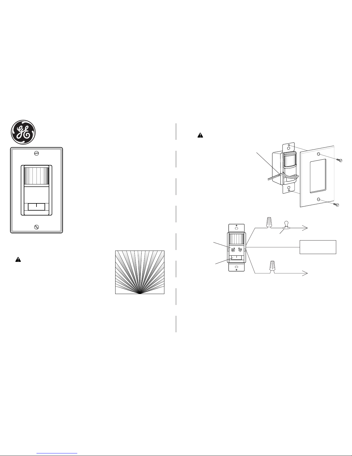
The Single Pole Motion S ensing Switch detects motion to turn on
lights for an adjustable amount of time. A built-in photo cell can be set
to keep lights off when the lights aren't needed. The unit has excellent
sensitivity and a wide 150° detection range. It can be used with incandescent lighting as well as rapid start fluorescent lighting.
Install ation is as easy as replacing a wall switch. However, some
codes require installation by a qualified electrician.
Features include:
• 150° motion detection angle.
• Adjustable on-time from 5 sec. to 20 min.
• Adjustable photocell.
• Works with incandescent and rapid start fluorescent lighting.
• Works with motors up to 1/8 hp.
• Slide switch selectable OFF, ON AND AUTO modes.
WARNING: Turn power off at the circuit breaker before wiring.
TYPICAL INSTALLATION
• Remove the decorative coverplate (secured by two
screws).
• Remove Control Cover. (Press in with screwdriver.
Swing out cover to remove.)
• Remove the existing switch (if this is a retrofit
application).
• Connect the detector as shown in the diagram.
Before installing the detector into the box, make
sure there is no wire exposed at the connection.
OF
F
N
O
AU
TO
- 2 -
• Mount the detector into the wall box with the mounting screws.
• For test p urposes, use a small screwdriver to turn th e time control fully counter-clockwise and the light
control fully clockwise. Turn the power back on at the circuit breaker.
• Set the switch to the AUTO mode. When unit stabilizes (about 1 minute), the sensor is ready to detect motion.
If motion is detected, the lights will turn on. The lights will turn off 5 seconds after motion is no longer detected.
Control Cover
Plate Removed
MODE
Selection
Switch
TIM E LIG HT
+ +
WHITE
(NEUTRAL)
Green ground wire to
junction box screw or
grounding wire.
BLACK
BLACK
BLACK
(LINE)
LIGHTING
LOAD
GENERAL APPLICATION INFORMATION
The detector is more sensitive to motion across the front of the sensor than to motion towards the sensor.
The detector senses heat in motion and possible heat sources that change temperature quickly. Therefore, to
avoid false triggering, avoid placing the sensor where it will be aimed at air conditioners, heaters, and other
sources of heat or cold.
NEW APPLICATION
Choose a location where the motion sensor has a clear view of
the entire area where occupant motion may occur.
RETROFIT APPLICATION
Motion sensing switch will replace existing wall switch. Use only
where the existi ng switch location provides a clear view of the
occupied area.
Included are: • The sensor switch • Cover plate • 3 wire connectors • 2 large screws • 2 small screws.
INSTALLATION
INSTALLING THE SWITCH
SELECT A LOCATION
Typical Plan View of Coverage
30'
15'
0'
WARNING: For indoor use only.
Questions? Call 1-800-654-8483 Or visit us at www.jascoproducts.com
598-1106-03
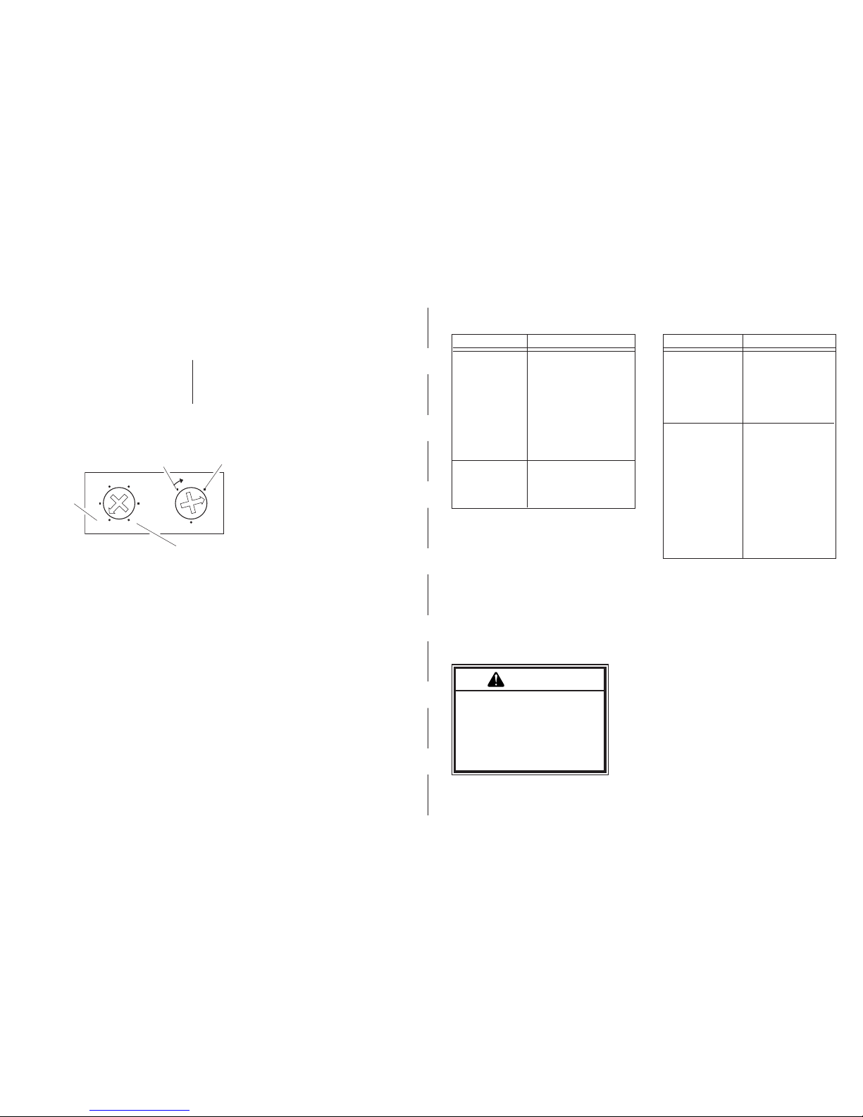
There are 6 preset selections for the amount
of time the lights stay on: Test (5 seconds), 1,
5, 10, 15, and 20 minutes. Use a small, phillips
screw driver to adjust the TIME control (see
Figure 4). Tur n the TIME control until it “snaps”
into the desired time position.
Replace control panel cover and install the decorative wall plate. In installations where the GE motion sensor
switch is combined with other switches or outlets on an expanded box, a combination wall plate will need to
be purchased. Various combination wall plates are available at Home Centers and Electrical Supply Stores.
Slide the switch a couple of times to make sure it operates freely.
When the light in the room is at the
level you want the lights to turn on,
set the switch to the AUTO position.
Put the TIME control t o the 5 second position.
Put the LIG HT control to th e minimum dark (ful ly counter-clockwise)
position. Wait for the lights to turn
off.
Turn the LIGHT adjustment clockwise in very small steps and wait 2
seconds before moving your hand in
front of the sensor. Repeat until the
lights controlled by the sensor come
on. The light will now come on when
the light level is at or below the present level and motion is detected.
To adjust the photocell:
MODE Selection Switch
Moving the switch selects one of three modes of operation: OFF, AUTO, ON
OFF: Lights stay off.
AUTO: Lights come on for time set when motion is detected and the light level is below the set level.
ON: Lights stay on continuously.
•
•
•
•
•
•
The senso r can be prevente d from turnin g on l ights
when there is already enough light in the room. Use a
small phillips screw driver to set the light level using this
diag ram as a guide. In the full y clockw ise posi tion ,
the sensor turns on ligh ts even in f ull daylight. I n the
fully counter-clockw ise position, the sen sor only tu rns
on lights when the surroundin g light level i s very low.
ADJUSTMENTS
USE
TIME
Complete Installation
LIGHT LEVEL
- 3 -
Electrical input............ ................. ................. ................. ................. ................. ................. ..............120 V, 60 Hz
Fluorescent Load.............................................(2 tube minimum) 30 Watt minimum 400 Watt maximum Rapid Start
Motor Load................... ................. .................. ................. ................. ................. ................. ...1/8 HP maximum
Incandes cent...... ......... .......... .......... ......... .......... ......... .......... .......... ......... .......... .......... ......... 500W maximum
On-Time.............. ....................... ........................ ....................... ......Adjustable approximately 5 sec. to 20 m in.
Photocell Sensor.................................... .......................... ......................... From full daylight to less than 1 FC.
Coverage...............................................................................up to 15 ft. at 150°, up to 30 ft. in front of the sensor
SPECIFICATIONS
TROUBLESHOOTING
- 4 -
SYMPTOM
Light does not
come on.
Lights do not stay
on in the Auto mode.
POSSIBLE CAUSE
Circuit breaker or fuse is
turned off.
If the lam p bei ng c on trolled has another switch,
it may be turned off.
Bulb is defective.
LIGHT control is set too far
toward the DARK position.
MOD E swit ch i s set t o
OFF instead of AUTO.
Poor connection.
Motion has stopped in the
room.
TIME control is set for too
short a delay.
1.
2.
3.
4.
5.
6.
1.
2.
SYMPTOM
Light does not
turn off.
Light comes on for
no reason in the Auto
mode.
POSSIBLE CAUSE
Incorrect wiring.
MODE switch is set to
ON instead of AUTO.
Motion is still present.
De lay set by TI ME
c on tr o l h as n ot
expired.
Heating or cooling obje cts (s uch a s ai r
vents, appli ances, or
drafts through the wall
box) are causing false
triggering.
Switch on the sensor
has been tu rne d off
and back on.
There was a momentar y power in ter rup tion. The light will turn
off automatically when
the "on" time expires.
1.
2.
3.
4.
1.
2.
3.
WARNING
Risk of electric shock
• Shut off power at fuse box or
circuit breaker before installation
• Use indoors only
Risk of fire
• Do not exceed electrical ratings
T I M E L I G H T
+
Test 20
151
5 10
Dark (low
light level)
Any Light Level
5 Seconds
20 Minutes
 Loading...