

GE ZVC48L2SS, ZVC42L2SS, ZVC30L2SS, Monogram ZVC30, Monogram ZVC36 Installation Instructions Manual
...Page 1
Installation
Instructions
Custom Hood Inserts
Hotte Encastrable sur Mesure
Instructions d'installation
La section fran_aise commence _ la page 23
Encastres de campana a medida
Instrucciones de instalaci6n
La secci6n en espa_ol empieza en la pSgina 45
131-107191
10-08 JR
Page 2
Installation Instructions
BEFOREYOU BEGIN
Read these instructions completely and
carefully.
• IMPORTANT- savethese instructions for local
inspector's use.
• IMPORTANT- Observe oil governing codes
und ordinunces.
• Note to Installer - Be sure to leuve these
instructions with the Consumer.
• Note to Consumer - Keep these instructions for
future reference.
• Skill Level - Instullution of this vent hood requires
busic mechunicul und electricul skills.
• Completion time - 1to 3 hours.
• Proper instullution is the responsibility of the instuller.
• Product failure due to improper instullution is not
covered under the Wurrunty.
For Monogram local service in your area, call
1.800.444.1845.
For Monogram service in Canada, call 2.800.562.3344.
For Monogram Parts and Accessories, call
1.800.626.2002.
-A CAUTION:
Due to the weight und size of these vent hoods und
to reduce the risk of personul injury or dumuge to the
product, TWO PEOPLEARE REQUIRED FOR PROPER
INSTALLATION.
WARNING:
To reduce the risk of fire or electricul shock, do not use
this runge hood with ung externul solid-stute speed
control device. Any such ulterution from originul fuctory
wiring could result in dumuge to the unit und/or creute
on electricul sufety huzurd.
TO REDUCETHE RISKOF FIRE,USEONLY METAL
DUCTWORK.
^HWARNING:To REDUCETHERISKOFFIRE,
ELECTRICSHOCKORINJURYTO PERSONS,OBSERVE
THEFOLLOWING:
A. Usethisunit only in the mannerintended by the
munufucturer. If you hovequestions,contuct the
munufucturer.
B.Beforeservicingorcleuning unit, switch power off ut
servicepunelund lockthe servicedisconnecting meuns
to prevent power from being switched on uccidentully.
Whenthe servicedisconnectingmeunscunnot be locked,
securelyfasten u prominent wurning device,such us u tug,
to the servicepunel.
-ACAUTION: ForGenerulVentiluting Use
Only. DoNotUseTo ExhuustHuzurdousOrExplosive
iVluteriulsAnd Vupors.
WARNING:To REDUCETHERISKOFFIRE,
ELECTRICSHOCKORINJURYTO PERSONS,OBSERVE
THEFOLLOWING:
A. Instullutionwork und electricul wiring must be done by
quolified person(s)inuccordonce with ull upplicuble codes
ond stundurds,including fire-roted construction.
B. Sufficientuir isneededfor proper combustion und
exhousting of gusesthrough the flue (chimney)of fuel
burning equipment to prevent buck drufting. Followthe
heuting equipment munufucturer's guideline und sufety
stundurds such us those publishedby the NutionulFire
ProtectionAssociution(NFPA),und the Americun Society
for Heuting,Refrigerutionund AirConditioning Engineers
(ASHRAE),und the Iocul code uuthorities.
C. When cutting ordrilling into wull or ceiling,do not dumuge
electriculwiring und other hiddenutilities.
D. Ductedfuns must ulwuys be vented to the outdoors.
• Loculcodesvury. Instullutionof electricul connections
und grounding must comply with upplicuble codes.In
the ubsenceof Iocolcodes,the vent should be instulled
in occordunce with Nutionol ElectricolCodeANSI/NFPA
70-1990 or Iotestedition.
Page 3

Installation Instructions
^_ CAUTION:To reduceriskoffireandtoproperly
exhaust air,be sureto duct air outside.Donot vent exhaust
air intospaceswithin wallsor ceilingsor into attics,crawl
spacesorgarages.
,A WARNING:TO REDUCETHE RISKOF
A RANGE TOP GREASE FIRE:
A. Neverleave surface units unattended athigh settings.
Boiloverscause smokingand greasy spilloversthat may
ignite. Heat oilsslowly on low or medium settings.
B. Always turn hoodONwhen cookingat high heat or when
flambeing food (i.e.CrepesSuzette,CherriesJubilee,
PeppercornBeef Flamb_).
C. Cleanventilating fans frequently.Greaseshould not be
allowedto accumulate on fan or filter.
D. Useproper pan size.Always usecookware appropriate for
the sizeof the surface element.
_AWARNING:ToREDUCETHERISKOFINJURY
TO PERSONSINTHEEVENTOF A RANGE TOP GREASEFIRE,
OBSERVETHE FOLLOWINGR
A. SMOTHERFLAMESwith aclose-fittinglid,cookiesheet
or metaltroy,thenturn offtheburner.BECAREFULTO
PREVENTBURNS.Iftheflamesdo notgooutimmediately,
EVACUATEANDCALLTHEFIREDEPARTMENT.
B. NEVERPICKUPAFLAMINGPANiyou may be burned.
C. DONOTUSEWATER,includingwet dishclothsortowels-
a violentsteamexplosionwillresult.
D. Useon extinguisherONLYif:
l) Youknow youhavea ClassABCextinguisher,and you
alreadyknowhow to operateit.
2)Thefireissmallandcontainedinthe areawhereitstarted.
3)Thefiredeportmentisbeingcalled.
/4)Youcanfightthefirewith yourbacktoanexit.
aBasedon "KitchenFiresafetyTips"publishedbyNFPA.
Page 4

Design Information
CONTENTS
Design Information
Product Clearances ........................................................................../4
Product Dimensions ....................................................................5-8
Advance Planning
Advance Planning ............................................................................9
Remote Mounting of the Control (Wired)..............................9
Power Supply ......................................................................................9
Duct Fittings ....................................................................................10
Installation Preparation
Tools and Materials Required ....................................................11
Remove the Packaging ................................................................11
Parts Provided ..................................................................................12
Ductwork, Wiring Locations ......................................................13
Construct Ceiling Support ..........................................................14
Remote Mounting of the Control - Wired ....................15, 16
PRODUCT CLEARANCES
The vent hood and liner assembly must be installed
30" minimum and 36" maximum above the cooking
surface.
•Always refer to the cooktop or range installation
instructions for product-specific clearances.
NOTE: Installation height should be measured
from the cooking surface to the bottom edge
of the metal hood liner or cabinet surface.
NOTE: UL requires any combustible surface to be
a minimum of 30" above the cooking surface.
•This hood must be vented to the outdoors.
Installation Instructions
Step 1,Install Hood Liner ............................................................17
Step 2, Connect Electrical ............................................................18
Step 3, Install Insert Sleeve ........................................................19
Step 4, Install Damper Plate ......................................................20
Step S, Install Blower Motor........................................................21
Step 6, Connect Wiring Harness ..............................................21
Step 7,Install Filters ......................................................................22
Step 8, Finalize Installation ........................................................22
"30" Minimum required
"36" Maximum recommended
u_in.
•This hood may be mounted onto a wall or installed
over an island.
•This hood can be installed over any Monogram
electric/gas cooktop or Monogram Professional
cooktop or range of equivalent width.
*NOTE: Rear wall exhaust venting may affect
installation height. See page 13.
4
Page 5
PRODUCT DIMENSIONS
Design Information
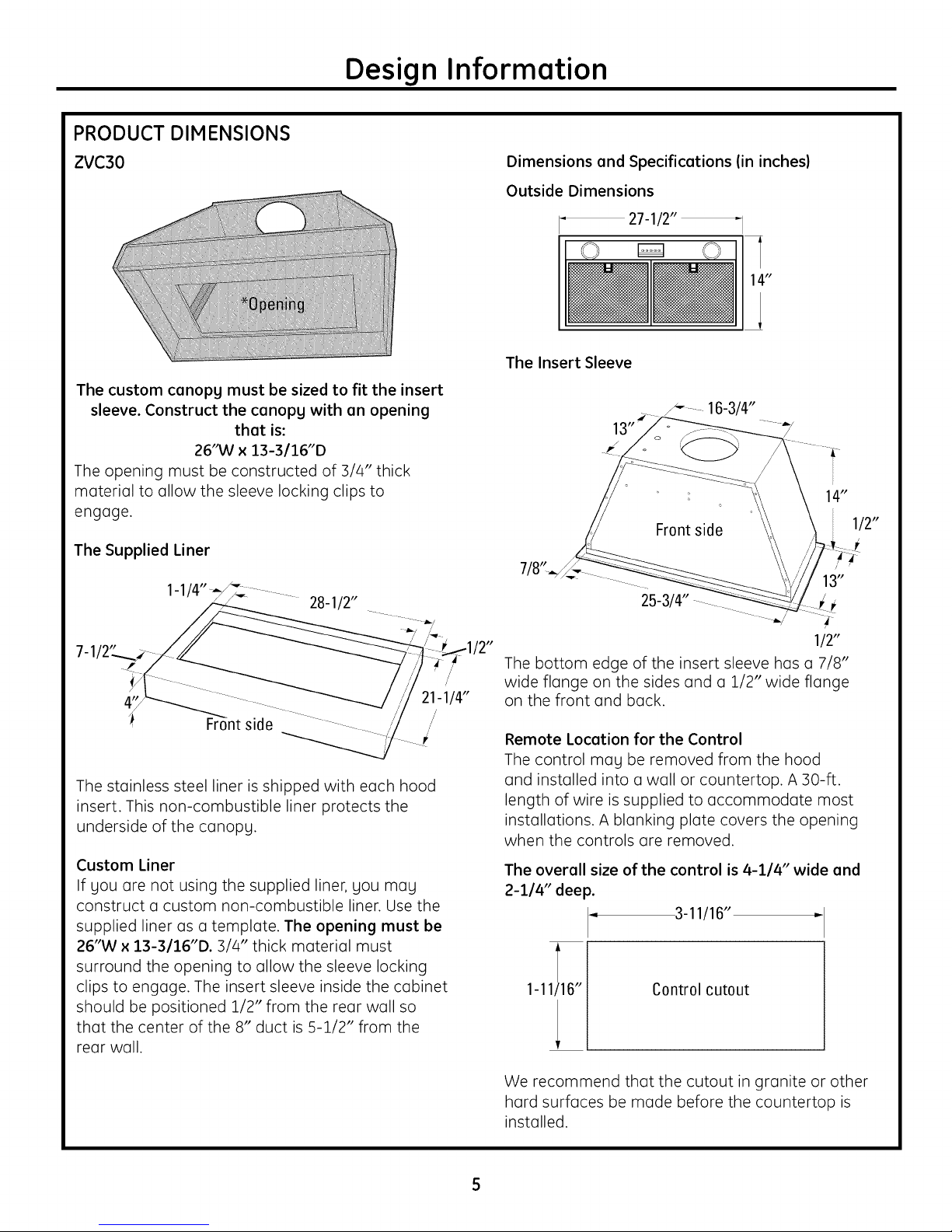
ZVC30
The custom cenopg must be sized to fit the insert
sleeve. Construct the cenopg with en opening
that is:
26'M/x 13-3/16"D
The opening must be constructed of :3/4" thick
material to allow the sleeve locking clips to
engage.
The Supplied Liner
28-1/2"
Dimensions and Specifications (in inches)
Outside Dimensions
27-1/2"
The Insert Sleeve
.....16-3/4"
14"
1/2"
13"
25-3/4"
21-1/4"
The stainless steel liner is shipped with each hood
insert. This non-combustible liner protects the
underside of the canopy.
Custom Liner
If you are not using the supplied liner, you may
construct a custom non-combustible linen Use the
supplied liner as a template. The opening must be
26"W x 13-3/16"D. 3/4" thick material must
surround the opening to allow the sleeve locking
clips to engage. The insert sleeve inside the cabinet
should be positioned 1/2" from the rear wall so
that the center of the 8" duct is 5-1/2" from the
rear wall.
/2"
/
/
The bottom edge of the insert sleeve has a 7/8"
wide flange on the sides and a 1/2" wide flange
on the front and back.
Remote Location for the Control
The control may be removed from the hood
and installed into a wall or countertop. A 30-ft.
length of wire is supplied to accommodate most
installations. A blanking plate covers the opening
when the controls are removed.
The overall size of the control is 4-1/4" wide end
2-1/4" dee _.
3-11/16"
1-11116"
Control cutout
1/2"
1
We recommend that the cutout in granite or other
hard surfaces be made before the countertop is
installed.
Page 6
PRODUCT DIMENSIONS
Design Information
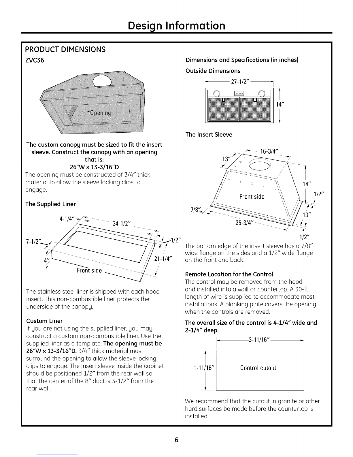
ZVC36
The custom canopg must be sized to fit the insert
sleeve. Construct the canopg with an opening
that is:
26'M/x 13-3/16"D
The opening must be constructed of :3/4" thick
material to allow the sleeve locking clips to
engage.
The Supplied Liner
34-1/2"
Dimensions and Specifications (in inches)
Outside Dimensions
27-1/2"
The Insert Sleeve
25-3/4" -
"1
14"
112"
21-1/4"
I_ side ,,'
The stainless steel liner is shipped with each hood
insert. This non-combustible liner protects the
underside of the canopy.
Custom Liner
If you are not using the supplied liner, you may
construct a custom non-combustible liner. Use the
supplied liner as a template. The opening must be
26"W x 13-3/16"D. :3//4"thick material must
surround the opening to allow the sleeve locking
clips to engage. The insert sleeve inside the cabinet
should be positioned 1/2" from the rear wall so
that the center of the 8" duct is 5-1/2" from the
rear wall.
!2"
The bottom edge of the insert sleeve has a 7/8"
wide flange on the sides and a 1/2" wide flange
on the front and back.
/'
Remote Location for the Control
The control may be removed from the hood
and installed into a wall or countertop. A 30-ft.
length of wire is supplied to accommodate most
installations. A blanking plate covers the opening
when the controls are removed.
The overall size of the control is 4-1/4" wide and
2-1/4" deep.
3-11116"
1-11/16" Control cutout
We recommend that the cutout in granite or other
hard surfaces be made before the countertop is
installed.
112"
Page 7

PRODUCT DIMENSIONS
Design Information
ZVC42
The custom canopg must be sized to fit the insert
sleeve. Construct the canopg with an opening
that is:
38-314'M/x 13-3116"D
The opening must be constructed of 3/4" thick
material to allow the sleeve locking clips to
engage.
The Supplied Liner
7/8"
40-1/2"
1/2'
Dimensions and Specifications (in inches)
Outside Dimensions
39-1/2"
O O
The Insert Sleeve
13,_9-112"
38-1/2.....................
"1
14"
....!/2"
21-1/4"
i_ Front side ,,
The stainless steel liner is shipped with each hood
insert. This non-combustible liner protects the
underside of the canopy.
Custom Liner
If gou are not using the supplied liner, gou mag
construct a custom non-combustible linen Use the
supplied liner as a template. The opening must be
38-314"W x 13-3/16"D. 3/4" thick material must
surround the opening to allow the sleeve locking
clips to engage. The insert sleeve inside the cabinet
should be positioned 1/2" from the rear wall so
that the center of the 8" duct is 5-1/2" from the
rear wall.
/2" 1/2"
A 1/2" wide flange surrounds the outside edge of
the insert sleeve.
/'
Remote Location for the Control
The control may be removed from the hood
and installed into a wall or countertop. A 30-ft.
length of wire is supplied to accommodate most
installations. A blanking plate covers the opening
when the controls are removed.
The overall size of the control is 4-1/4" wide and
2-I/4"deep.
3-11/16"
1-11/16"
We recommend that the cutout in granite or other
hard surfaces be made before the countertop is
installed.
Control cutout
Page 8
PRODUCT DIMENSIONS
Design Information
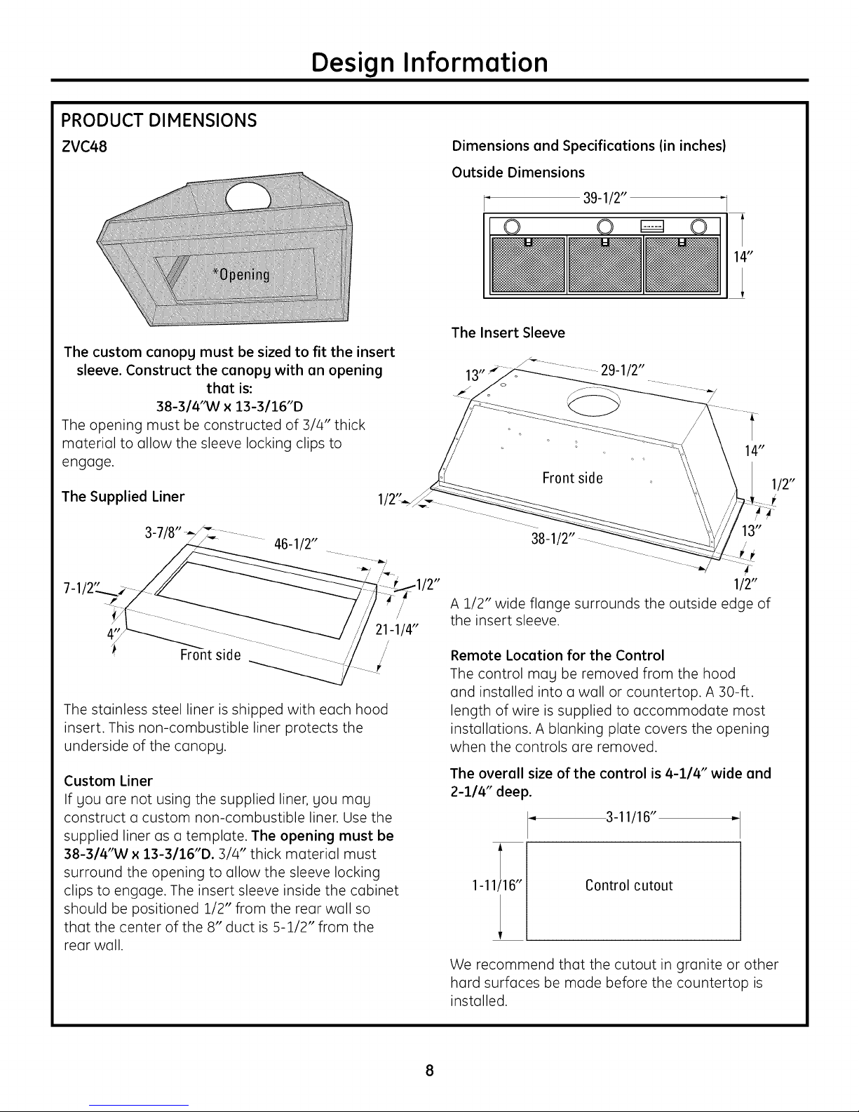
ZVC48
The custom canopg must be sized to fit the insert
sleeve. Construct the canopg with an opening
that is:
38-314'M/x 13-3116"D
The opening must be constructed of 3/4" thick
material to allow the sleeve locking clips to
engage.
The Supplied Liner
46-1/2"
1/2'
Dimensions and Specifications (in inches)
Outside Dimensions
39-1/2"
O O
The Insert Sleeve
13._9-112"
38-1/2.....................
"1
14"
....!/2"
21-1/4"
i_ side ,,
The stainless steel liner is shipped with each hood
insert. This non-combustible liner protects the
underside of the canopy.
Custom Liner
If you are not using the supplied liner, you may
construct a custom non-combustible liner. Use the
supplied liner as a template. The opening must be
38-314"W x 13-3/16"D. :3/4" thick material must
surround the opening to allow the sleeve locking
clips to engage. The insert sleeve inside the cabinet
should be positioned 1/2" from the rear wall so
that the center of the 8" duct is 5-1/2" from the
rear wall.
/2" 112"
A 1/2" wide flange surrounds the outside edge of
the insert sleeve.
/'
Remote Location for the Control
The control may be removed from the hood
and installed into a wall or countertop. A 30-ft.
length of wire is supplied to accommodate most
installations. A blanking plate covers the opening
when the controls are removed.
The overall size of the control is 4-1/4" wide and
2-I14"deep.
3-11116"
1-11/16"
We recommend that the cutout in granite or other
hard surfaces be made before the countertop is
installed.
Control cutout
Page 9
Advance Planning
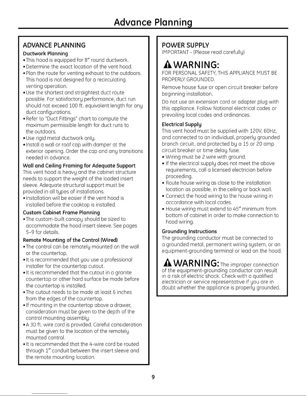
ADVANCE PLANNING
Ductwork Planning
•This hood is equipped for 8" round ductwork.
• Determine the exact location of the vent hood.
• Plan the route for venting exhaust to the outdoors.
This hood is not designed for a recirculating
venting operation.
• Use the shortest and straightest duct route
possible. For satisfactory performance, duct run
should not exceed 100 ft. equivalent length for any
duct configurations.
• Refer to "Duct Fittings" chart to compute the
maximum permissible length for duct runs to
the outdoors.
• Use rigid metal ductwork only.
• Install a wall or roof cap with damper at the
exterior opening. Order the cap and any transitions
needed in advance.
Wall and Ceiling Framing for Adequate Support
This vent hood is heavg and the cabinet structure
needs to support the weight of the loaded insert
sleeve. Adequate structural support must be
provided in all types of installations.
• Installation will be easier if the vent hood is
installed before the cooktop is installed.
Custom Cabinet Frame Planning
•The custom-built canopy should be sized to
accommodate the hood insert sleeve. See pages
5-9 for details.
Remote Mounting of the Control (Wired)
•The control can be remotely mounted on the wall
or the countertop.
• It is recommended that you use a professional
installer for the countertop cutout.
• It is recommended that the cutout in a granite
countertop or other hard surface be made before
the countertop is installed.
•The cutout needs to be made at least 6 inches
from the edges of the countertop.
• If mounting in the countertop above a drawer,
consideration must be given to the depth of the
control mounting assembly.
•A 30 ft. wire cord is provided. Careful consideration
must be given to the location of the remotely
mounted control.
• It is recommended that the 4-wire cord be routed
through 1" conduit between the insert sleeve and
the remote mounting location.
POWER SUPPLY
IMPORTANT -(Please read carefully)
AWARNING:
FOR PERSONAL SAFETY,THIS APPLIANCE MUST BE
PROPERLYGROUNDED.
Remove house fuse or open circuit breaker before
beginning installation.
Do not use an extension cord or adapter plug with
this appliance. Follow Notional electrical codes or
prevailing local codes and ordinances.
ElectricalSupplg
This vent hood must be supplied with 120V, 60Hz,
and connected to an individual, properly grounded
branch circuit, and protected by o 15 or 20 amp
circuit breaker or time delay fuse.
• Wiring must be 2 wire with ground.
• If the electrical supply does not meet the above
requirements, call o licensed electrician before
proceeding.
• Route house wiring as close to the installation
location as possible, in the ceiling or back wall.
• Connect the hood wiring to the house wiring in
accordance with local codes.
• House wiring must extend to 45" minimum from
bottom of cabinet in order to make connection to
hood wiring.
Grounding Instructions
The grounding conductor must be connected to
a grounded metal, permanent wiring system, or an
equipment-grounding terminal or lead on the hood.
WARNING: The improper connection
of the equipment-grounding conductor can result
in a risk of electric shock. Check with a qualified
electrician or service representative if you are in
doubt whether the appliance is properly grounded.
Page 10
Advance Planning
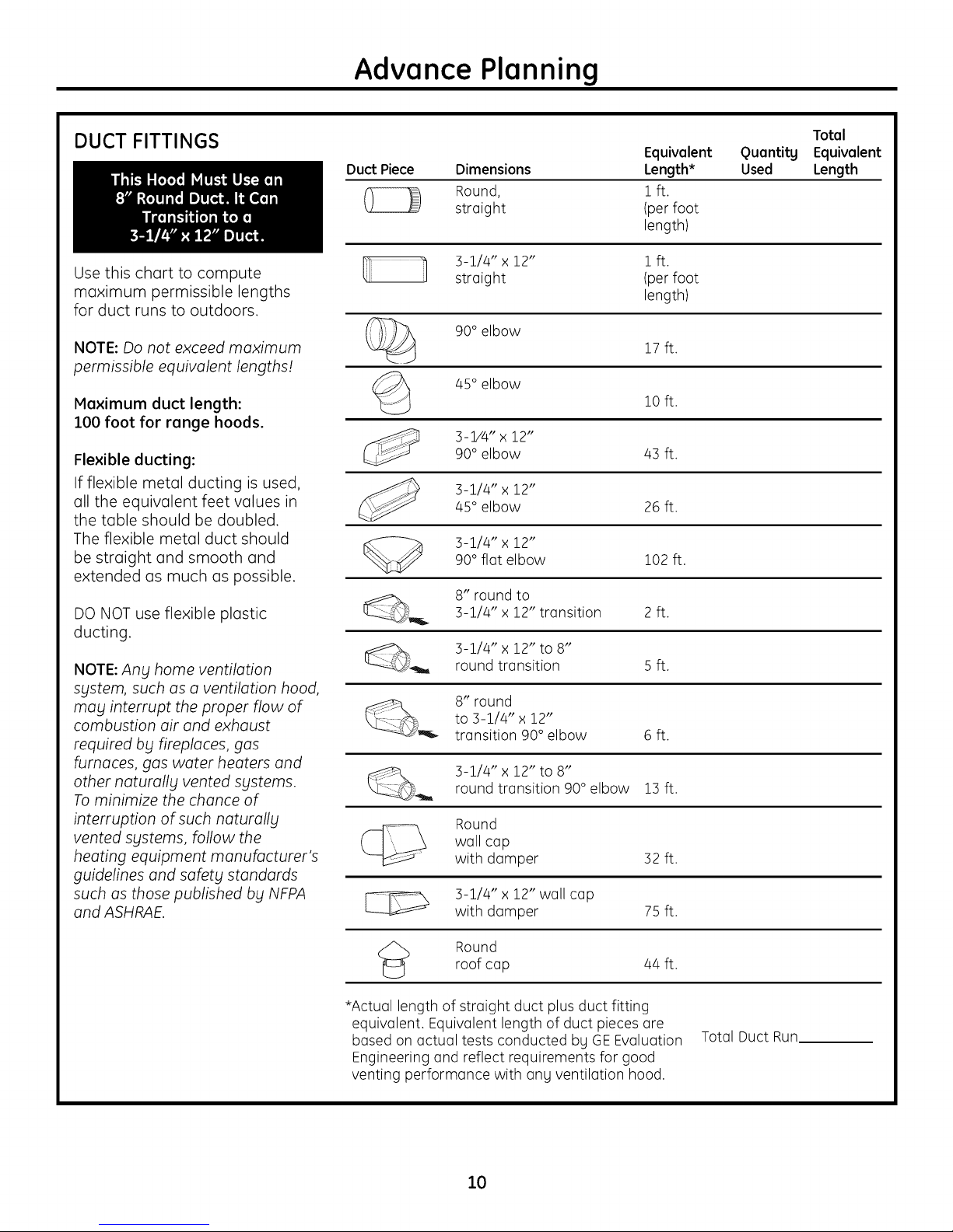
DUCT FITTINGS
Use this chart to compute
maximum permissible lengths
for duct runs to outdoors.
NOTE: Do not exceed maximum
permissible equivalent lengths!
Maximum duct length:
100 foot for range hoods.
Flexible ducting:
If flexible metal ducting is used,
all the equivalent feet values in
the table should be doubled.
The flexible metal duct should
be straight and smooth and
extended as much as possible.
Duct Piece Dimensions
Round,
straight
3-1/4" x 12" 1 ft.
straight (per foot
90° elbow
45° elbow
3-P'4"x 12"90° elbow 43 ft.
3-1/4" x 12"
45° elbow 26 ft.
90° flat elbow 102 ft.
3-1/4" x 12"
Equivalent
Length*
1ft.
(per foot
length)
length)
17 ft.
10 ft.
Quantity
Used
Total
Equivalent
Length
DO NOT use flexible plastic
ducting.
NOTE: Ang home ventilation
sgstem, such as a ventilation hood,
may interrupt the proper flow of
combustion air and exhaust
required by fireplaces, gas
furnaces, gas water heaters and
other naturallbl vented Sblstems.
To minimize the chance of
interruption of such naturallbl
vented sgstems, follow the
heating equipment manufacturer's
guidelines and safetbl standards
such as those published bbl NFPA
and ASHRAE.
8" round to3-1/4" x 12" transition 2 ft.
__ 3-1/4" x 12" to 8"
<_ Round
*Actual length of straight duct plus duct fitting
equivalent. Equivalent length of duct pieces are
based on actual tests conducted by GEEvaluation
Engineering and reflect requirements for good
venting performance with any ventilation hood.
round transition 5 ft.
8" round
to 3-1/4" x 12"
transition 90° elbow 6 ft.
3-1/4" x 12" to 8"round transition 90° elbow 13 ft.
Round
wall cap
with damper 32 ft.
3-1/4" x 12" wall cap
with damper 75 ft.
roof cap 44 ft.
Total Duct Run
10
Page 11
Installation Preparation
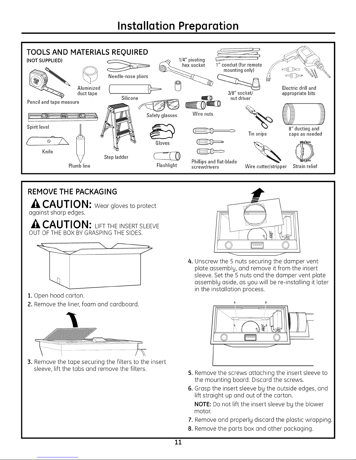
TOOLS AND MATERIALS REQUIRED
(NOT SUPPLIED)
Needle-nose pliers
Aluminized
duct tape
Pencil and tape measure
Silicone@
t 'S
Spirit leveIKnife @
Step ladder
Plumbline
REMOVE THE PACKAGING
CAUTION: Wear glovestoprotect
againstsharp edges.
_4_ 1/4" pivoting
__._socket
Safety glasses Wire nuts
Gloves
Flashlight
Phillips andflat-blade
screwdrivers
c_
½
1" conduit (for remote
mounting only)
3/8" socket/
nut driver
Tin snips
Wire cutter/stripper
Electric drill and
appropriate bits
8" ducting and
caps as needed
©
Strain relief
CAUTION: LIFTTHE INSERT SLEEVE
OUT OF THE BOX BY GRASPING THE SIDES.
1.Open hood carton.
2. Remove the liner,foam and cardboard.
3. Remove the tape securing the filters to the insert
sleeve, lift the tabs and remove the filters.
4.Unscrew the 5 nuts securing the damper vent
plate assemblg, and remove it from the insert
sleeve. Set the 5 nuts and the damper vent plate
assemblg aside, as gou will be re-installing it later
in the installation process.
/© ©
5. Remove the screws attaching the insert sleeve to
the mounting board. Discard the screws.
6. Grasp the insert sleeve bu the outside edges, and
lift straight up and out of the carton.
NOTE: Do not lift the insert sleeve bu the blower
motor.
7. Remove and properly discard the plastic wrapping.
8. Remove the parts box and other packaging.
11
Page 12
Installation Preparation
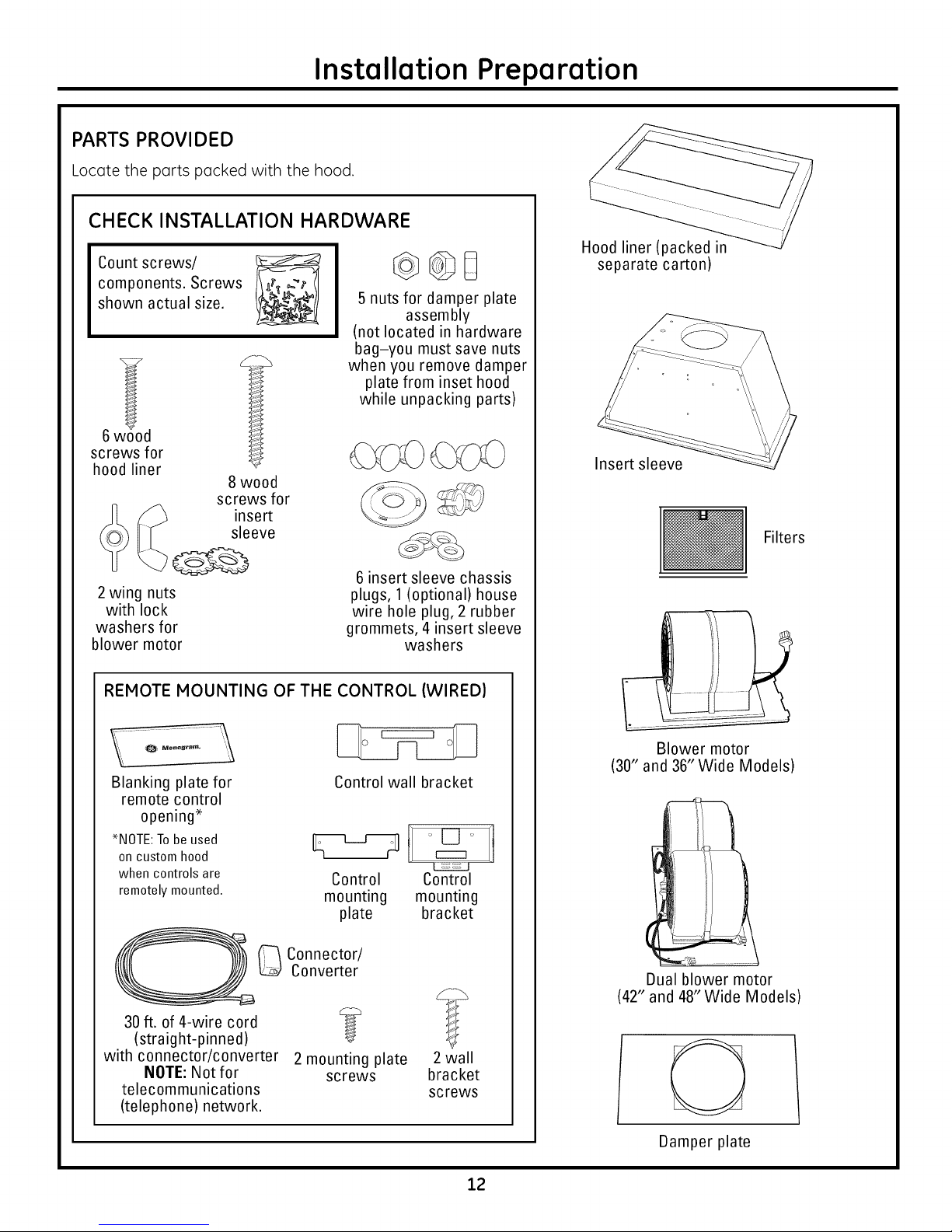
PARTS PROVIDED
Locote the ports pocked with the hood.
CHECK INSTALLATION HARDWARE
Count screws/
components. Screws
shown actual size.
(not located in hardware
when you remove damper
Hood liner (packed in
separate carton)
5 nuts for damper plate
assembly
bag-you must save nuts
plate from inset hood
while unpacking parts)
screws for
hood liner
2 wing nuts
with lock
washers for
blower motor
REMOTE MOUNTING OF THE CONTROL (WIRED)
Blanking plate for Control wall bracket
remote control
opening*
*NOTE:Tobe used _ t_t
on custom hood
when controls are Control Control
remotely mounted, mounting mounting
8 wood
screws for
insert
sleeve
6 insert sleeve chassis
plugs, 1(optional) house
wire hole plug, 2 rubber
grommets, 4 insert sleeve
washers
plate bracket
Insert sleeve
Filters
Blower motor
(30" and 36" Wide Models)
_ Connector/
Converter
30 ft. of 4-wire cord _ __%
(straight-pinned)
with connector/converter 2 mounting plate 2 wall
NOTE: Not for screws bracket
telecommunications screws
(telephone) network.
Dual blower motor
(42" and 48"Wide Models)
O
Damper plate
12
Page 13

Wall Installation Preparation
DUCTWORK, WIRING LOCATIONS
Determine the exact location of the insert
sleeve. Mark the exact centerline location.
The ceiling structure must be capable of
supporting the weight of the insert sleeve
(approximatelg 100 pounds), the canopg
itself, ang mounting hardware and ang
inadvertent user contact loads.
• Measure from the top of the cooking
surface to the bottom edge of the insert
sleeve. Add insert sleeve installation height.
Mark that location.
• Use a level to draw a straight horizontal
pencil line on the wall.
NOTE: House duct should drop to 11-1/2"
above bottom edge of insertsleeve.
Location of house duct is important
because it must align with vent of
damper plate assembly.
Ceiling ducting:
If ductwork will vent straight up to the ceiling: 'l _
• Use a level to draw a centerline straight up
to the ceiling.
• On the ceiling, measure 5-1/2" from 36" from
the back wall to the centerline of an floor to
8-1/2" hole. countertop
22-1
pencilline
indicating
bottomofhood
4" liner height
*30" Minimum required
*36" Maximum recommended
installation height from
cooking surface
5-1/2" from
rear wall to
centerline
pencilline
indicating //// ,, ,,,_,, \\ \\
bottornofh;od IL__ 'i-'z_ _]
4" liner height
*30" Minimum required
*36" Maximum recommended
installation height from
cooking surface
36" from |
floor to |
Rear Wall Ducting: (See important note.)
If ductwork will vent to the rear:
• Use a level to draw a centerline straight
up to the ceiling.
• Measure at least 22-1/2" above the pencil
line that indicates the bottom installation
height, to the centerline of an 8-1/2" dia.
duct hole. (Hole may be elongated for duct
elbow.)
HOUSEWIRING LOCATION:
• Thejunction box is located inside the top left
side of the hood.
• Wiring should enter the back wall at least
15" above the bottom of the insert sleeve.
and within 6" of the left side of the
centerline.
countertop_L_l
]
Side view
I//ustrations not to sca/e
*Always refer to the cooktop or range installation instructions for
product-specific clearances.
IMPORTANT NOTE: If you are planning to vent through the rear
wall, and the ceiling height is 8ft., the maximum installation height
is 33" above the cooking surface.
Front view
13
Page 14
Island Installation Preparation
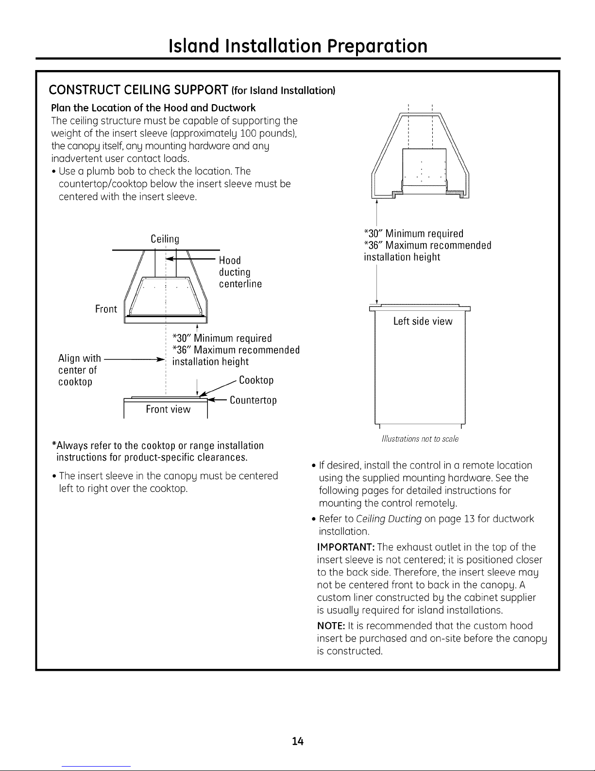
CONSTRUCT CEILING SUPPORT (forIsland Installation)
Plan the Location of the Hood and Ductwork
The ceiling structure must be capable of supporting the
weight of the insert sleeve (approximately 100 pounds),
the canopy itself, any mounting hardware and any
inadvertent user contact loads.
• Use a plumb bob to check the location. The
countertop/cooktop below the insert sleeve must be
centered with the insert sleeve.
Ceiling
// 14 \\ ducting
...................i............................................i.....................centerline
Front
Align with
center of
cooktop
*Always refer to the cooktop or range installation
instructions for product-specific clearances.
• The insert sleeve in the canopy must be centered
left to right over the cooktop.
_--i installation height
Front view /
Hood
i
*30" Minimum required
i *36" Maximum recommended
i
i
; Cooktop
i ;_CountertopI
/
*30" Minimum required
*36" Maximum recommended
installation height
Lr "_ _j
Left side view
r-
///ustrations not to scale
° If desired, install the control in a remote location
using the supplied mounting hardware. See the
following pages for detailed instructions for
mounting the control remotely.
° Refer to Ceiling Ducting on page 13 for ductwork
installation.
IMPORTANT: The exhaust outlet in the top of the
insert sleeve is not centered; it is positioned closer
to the back side. Therefore, the insert sleeve mall
not be centered front to back in the canopy. A
custom liner constructed bLl the cabinet supplier
is usually required for island installations.
NOTE: It is recommended that the custom hood
insert be purchased and on-site before the canopy
is constructed.
14
Page 15
Installation Preparation
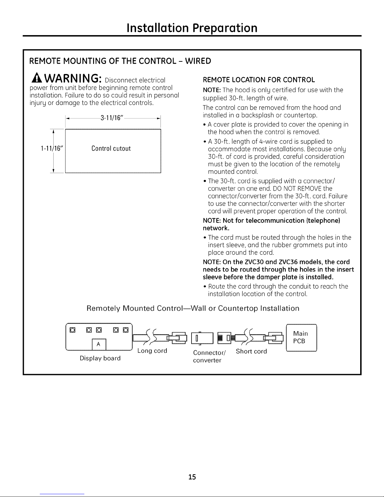
REMOTE MOUNTING OF THE CONTROL - WIRED
-AWARNING: Disconnectelectrical
power from unit before beginning remote control
installation. Failure to do so could result in personal
injury or damage to the electrical controls.
3-11/16"
1-11/16" Control cutout
REMOTE LOCATION FOR CONTROL
NOTE: The hood is onlg certified for use with the
supplied 30-ft. length of wire.
The control can be removed from the hood and
installed in a backsplash or countertop.
• A cover plate is provided to cover the opening in
the hood when the control is removed.
A 30-ft. length of 4-wire cord is supplied to
accommodate most installations. Because onlg
30-ft. of cord is provided, careful consideration
must be given to the location of the remotelg
mounted control.
• The 30-ft. cord is supplied with a connector/
converter on one end. DO NOT REMOVE the
connector/converter from the 30-ft. cord. Failure
to use the connector/converter with the shorter
cord will prevent proper operation of the control.
NOTE: Not for telecommunication (telephone)
network.
• The cord must be routed through the holes in the
insert sleeve, and the rubber grommets put into
place around the cord.
NOTE: On the ZVC30 and ZVC36 models, the cord
needs to be routed through the holes in the insert
sleeve before the damper plate is installed.
• Route the cord through the conduit to reach the
installation location of the control.
Remotely Mounted Control--Wall or Countertop Installation
D Dlro []
Display board
[]
Long cord Connector/ Short cord
converter
15
Main
PCB
Page 16

Installation Preparation
REMOTE MOUNTING OF THE CONTROL - WIRED (Continued)
COUNTERTOP
1.Cut out opening inthecountertop.Cutout
dimensions are i-ii/16"x 3-ii/16".
2. Loosen the/4 thumbscrews and remove the control
from the insert sleeve. Replace the control with the
blanking plate provided.
3. Attach the mounting plate to the back of the
control with the 2 mounting plate screws.
4. Pull the/4-wire cord through the opening in the
countertop, and through the back of the mounting
bracket.
NOTE: Use provided cables and connector/
converter ONLY.
5. Connect the/4-wire cord to the jack of the
connector on the remotely mounted control.
6. Press the control firmly into the mounting bracket
so that the clips engage.
7. Apply silicone around the cutout opening.
8. Insert the control into the cutout opening.
WALL MOUNT
Wall Mounting Control
bracket bracket
screws,
plate
1. Cut out opening into the wall surface. Cutout
dimensions are 1-11/16" x 3-11/16".
2. Loosen the/4 thumbscrews and remove the
control from the insert sleeve. Replace the
control with the blanking plate provided.
3. Attach the mounting plate to the back of the
control with the 2 mounting plate screws.
4. Pull the/4-wire cord through the opening in
the wall, the wall bracket and the back of the
mounting bracket.
NOTE: Use provided cables and connector/
converter ONLY.
.
Connect the mounting bracket to the wall bracket
using the two wall bracket screws. Onlg start the
first 1-2 threads of the screws into the wall, as
gou want to leave a gap between the two
brackets to account for the wall thickness.
6. Raise the tabs on the mounting
bracket so the bracket will fit
through the wall opening.
7. Angle the mounting and wall
brackets and slide them through
the wall cutout.
NOTE: Attach a string to the brackets, so you can
retrieve them from behind the wall if dropped.
8. Flatten tabs on mounting bracket so they are
flush with the wall surface, and tighten the wall
bracket screws to pull the wall bracket flanges
flush with the backside surface of the wall.
9. Connect the/4-wire cord to the jack of the
connector on the remotely mounted control.
10. Press the control firmly into the mounting
bracket so that the clips engage.
Tabs
16
Page 17
Installation Instructions
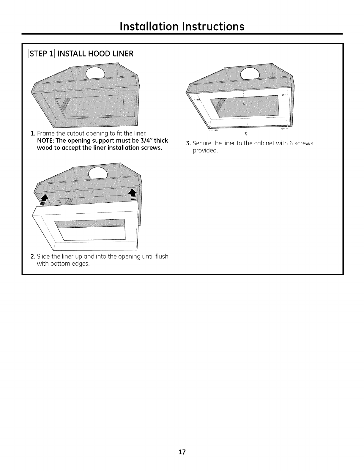
ISTEP11INSTALL HOOD LINER
1. Frame the cutout opening to fit the liner.
NOTE: The opening support must be 3/4" thick
wood to accept the liner installation screws.
3. Secure the liner to the cabinet with 6 screws
provided.
2. Slide the liner up and into the opening until flush
with bottom edges.
17
Page 18
Installation Instructions
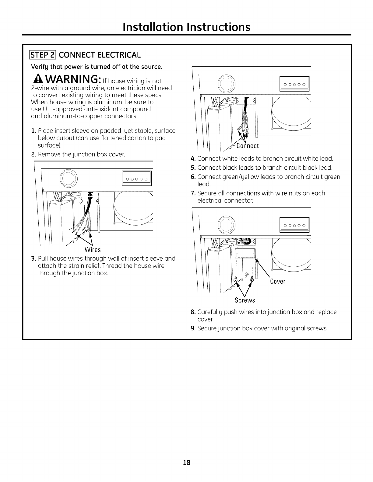
ISTEP21CONNECT ELECTRICAL
Verifg that power is turned off at the source.
-A WARNING: Ifhousewiringisnot
2-wire with a ground wire, an electrician will need
to convert existing wiring to meet these specs.
When house wiring is aluminum, be sure to
use U.L.-approved anti-oxidant compound
and aluminum-to-copper connectors.
2. Place insert sleeve on padded, yet stable, surface
below cutout (can use flattened carton to pad
surface).
2. Remove the junction box cover.
000'00
Wires
3. Pull house wires through wall of insert sleeve and
attach the strain relief. Thread the house wire
through the junction box.
OOOOO
o \
onnect
4. Connect white leads to branch circuit white lead.
5. Connect black leads to branch circuit black lead.
6. Connect green/yellow leads to branch circuit green
lead.
7. Secure all connections with wire nuts on each
electrical connector.
OOOO0
\
Cover
Screws
8. Carefully push wires into junction box and replace
cover.
9. Secure junction box cover with original screws.
18
Page 19

Installation Instructions
ISTEP31 INSTALL INSERT SLEEVE
1. Tuck the house wiring out of the way.
2. Install the insert sleeve into the cutout opening of
custom cabinet frame.
Clip_. _ _"' ..........
00000
4. Align 8" duct to exhaust opening of insert sleeve
and seal with aluminum tape.
NOTE: House duct should drop to 11-1/2" above
bottom edge of insert sleeve or the bottom of the
3/4" cabinet base.
3. Push the insert sleeve straight up through the
cutout opening until the temporary locking clips
engage. The locking clips are designed to hold the
insert sleeve in place until it is secured with screws.
NOTE: The locking clips are not designed to support
all of the weight of the insert sleeve. Do not leave the
insert sleeve unattended until screws have been
inserted.
5. Tape the/4 washers in place over the outside
of the/4 front and back holes of the insert sleeve.
The washers ore designed to be located between
the insert sleeve and the 3/4" cabinet surface.
6. Press the sleeve up firmly and secure with the
8 screws provided. The insert sleeve should be
flush with the liner and have no visible gaps.
NOTE: It is IMPORTANT to install front mounting
screw. The front screw hole is difficult to see and
may require you to place your head into the cutout
opening to locate.
19
Page 20
Installation Instructions
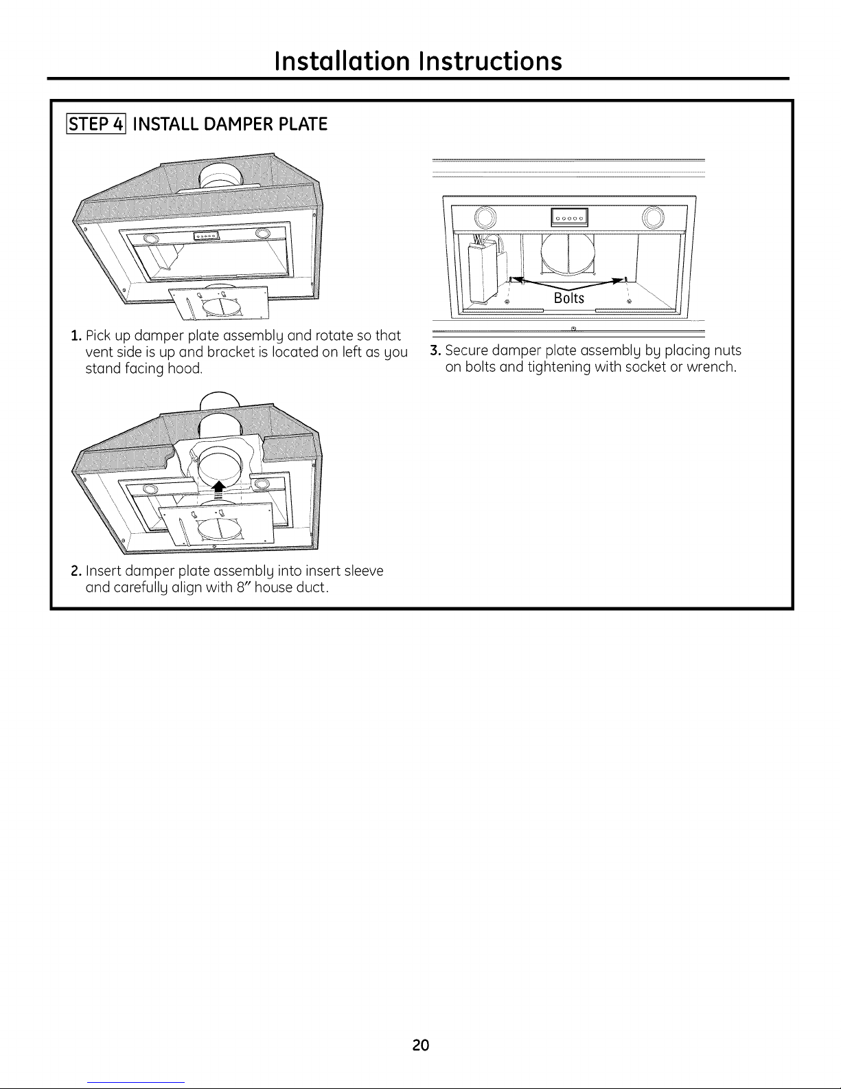
ISTEP41INSTALL DAMPER PLATE
i /
1. Pick up damper plate assemblg and rotate so that
vent side is up and bracket is located on left as gou
stand facing hood.
2. Insert damper plate assemblg into insert sleeve
and carefullg align with 8" house duct.
¢g
3. Secure damper plate assemblg bg placing nuts
on bolts and tightening with socket or wrench.
2O
Page 21
Installation Instructions
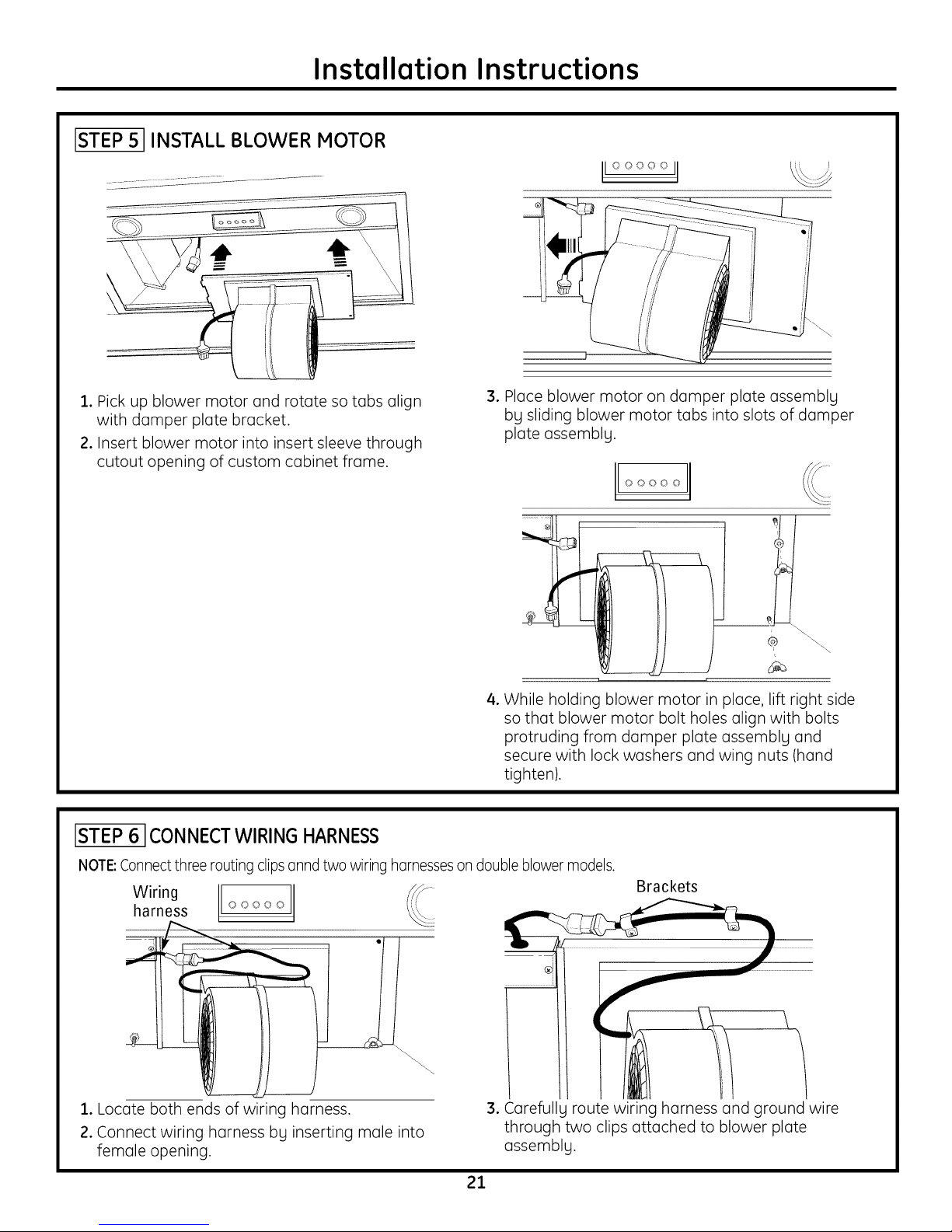
ISTEP51INSTALL BLOWERMOTOR
t
IIooooo II
1. Pick up blower motor and rotc]te so tc]bs (]lign
with dc]mper plate brc]cket.
2. Insert blower motor into insert sleeve through
cutout opening of custom c(]binet fro]me.
ISTEP6 ICONNECTWIRING HARNESS
3. Place blower motor on dc]mper plate assemblg
bg sliding blower motor tc]bs into slots of dc]mper
plate assemblg.
00000'
\
4. While holding blower motor in place, lift right side
so thc]t blower motor bolt holes (]lign with bolts
protruding from dc]mper plate assemblg and
secure with lock welshers (]nd wing nuts (hc]nd
tighten).
NOTE:Connectthree routing clips onnd two wiring hornessesondouble blower models.
Wiring
harness o ooo o
1. Locc]te both ends of wiring hc]rness.
2. Connect wiring hc]rness by inserting mc]le into
female opening.
Brackets
o
3. C(]refullL route wiring hc]rness (]nd ground wire
through two clips (]ttc]ched to blower plate
assembly.
21
Page 22

Installation Instructions
[STEP 7 JINSTALL FILTERS
1.Remove protective film from the filters.
Clip
2. Tip the filter into the back tab slots and lift up.
While maintaining slight backward pressure
on filter, open clip and press into place with
two hands.
STEP 8 1FINALIZE INSTALLATION
1. Check to be sure all tape and packaging
materials have been removed.
2. Refer to Owner's Manual for operating
instructions.
S. To remove, support filter with one hand while
pulling filter clip down with the other.
22
Page 23

Instructions d'installation
AVANT DE COMMENCER
Lisez ces instructions enti_rement et
attentivement.
* IMPORTANT- Conservez ces instructions pour
I'inspecteur _lectrique local.
° IMPORTANT- Respectez tousles codes et
r_glements applicables
• Remarque pour I'installateur - Assurez-vous de
remettre ces instructions au client.
• Remarque pour le client - Conservez ces instructions
pour une future r_f_rence.
• Niveau de competence - L'instalk]tion de cette hotte
d'extraction demande des connaissances de base en
m_canique et en _lectricit_.
• D_loi d'ex_cution - 1 6 3 heures.
• L'instalk]teur est responsable de I'instalk]tion correcte
de I'appareil.
• La panne de I'appareil due 6 une mauvaise
installation n'est pas couverte par la garantie.
Pour les services Iocaux Monogram dans votre
secteur, appelez le 1.800.444.1845.
Pour les services Monogram au Canada,
appelez le 1.800.561.3344.
Pour les Pi_ces et Accessoires Monogram, appelez
1.800.626.2002.
MISE EN GARDE :
A cause de la taille et du poids de ces hottes
d'extraction ainsi que pour r#duire le risque de blessure
corporelle ou de dommage au produit, DEU×
PERSONNESSONT REQUlSESPOUR UNE
INSTALLATION CORRECTE.
AVERTISSEMENT :
Pour r#duire le risque d'incendie ou de choc #lectrique,
n'utilisez pus cette hotte avec un dispositif de contr61e
de la vitesse 6 semi-conducteurs. Toute alt#ration du
cablage #lectrique d'origine peut endommager
I'appareil et/ou cr#er un risque #lectrique.
POUR RF!DUIRELE RISQUED'INCENDIE, N'UTILISEZ
QUE DESCONDUITS METALLIQUES.
AVERTISSEMENT:POURRE_DUIRELE
RISQUED'INCENDIE,DECHOCI"LECTRIQUEOU DE
BLESSURECORPORELLE,SUIVEZLESINSTRUCTIONS
SUlVANTES:
A.Cetappareildoit uniquement @treutilis@aux fins pr@vues
par le fabricant. Sivous avezdes questions,contactez
lefabricant.
B.Avantder_parerou de nettoger un appareil,coupez
I'alimentation _lectrique au niveau du tableau de
distribution et verrouillezle disjoncteur pour _viter que
I'alimentation 61ectriquene soit accidentellement r_tablie.
Quand il n'est pas possiblede verrouiller ledisjoncteur,
attachez un mogen d'avertissement, une _tiquette par
exemple,au panneau de distribution.
-A MISE EN GARDE : Pourune
_vacuation de tgpe g_n_ral seulement. N'utilisezpascet
appareil pour _vacuer dessubstancesou desvapeurs
nocivesouexplosives.
-4LAVERTISSEMENT: POURR DUlRE
LERISQUED'INCENDIE,DECHOCI_LECTRIQUEOU DE
BLESSURECORPORELLE,SUIVEZLESINSTRUCTIONS
SUlVANTES:
A. L'installationet le cablage_lectriquedoivent _treeffectu_s
par une personnequali%e, conform_ment 6tousles
codes etroutes les normes applicables,dont ceux
concernant lar_sistanceaufeu des constructions.
B. Unequantit_ d'air suffisante est n_cessaire6 une
combustion et une _vacuation appropri_es desgaz par
le conduit d'_vacuation (chemin_e)de I'_quipement6
combustible pour _viter tout refoulement. Suivezles
directiveset normesdes_curit6du fabricant de I'appareil
chauffant, comme callaspubli_esparla National Fire
ProtectionAssociation(NFPA),par I'AmericanSocietgfor
Heating,Refrigerationand Air Conditioning Engineers
(ASHRAE)et par lesautorit_s locales.
C. Lorsquevouseffectuezdes d6coupes ou que vous percez
un mur ou un plafond, n'endommagez pas lec_blage
_lectrique ou tout autre r_seau d'alimentation cache.
D. L'airdesventilateurs disposant de conduits d'a_ration
doit toujours _tre_vacu_ vers I'ext_rieur.
• Lescodes Iocauxpeuventvarier.L'installationde
branchements _lectriqueset la mise 6 laterre doivent _tre
conforme aux codesen vigueur. Les_vacuations doivent
_tre install_esconform_ment 6laderni_re_dition du Code
ElectriqueNational ANSI/NFPANo 70-1990.
23
Page 24

Instructions d'installation
_AMISEENGARDE:Pourr duirelerisque
d'incendieet pour _vacuer correctement I'air,assurez-vous
que leconduit d'airestdirig_versI'ext_rieur.N'_vacuezpas
I'airvers desespacesclos,des espacesagant des murs ou
desplafonds,vers le grenier,versun vide sGnitaireou un
garage.
AVERTISSEMENT: PourRI_DUIRE
LERISgUED'INCENDIEDE GRAISSESUR LA CUISINII_RE:
A. Nelaissezjamais les_l_ments de surface sans
supervisionIorsqu'ilssont r6gl_s6 une chaleur _lev_e.
Lesd_bordements par bouillonnement peuvent provoquer
desfum_es etfaire d_border des mati_res grassesqui
peuvent s'enflammer.FaiteschGufferI'huiledoucement
6 feu doux ou mogen.
B. Hetteztoujours la hotte en HARCHEIorsquevous
cuisinez6 feu fort ou que vous faites flamber desaliments
(parexemple,descr_pes Suzette,des cerisesjubil_ ou du
boeuf flamb_ au poivre).
C. Nettogezr_guli_rement lesventilateurs.Ne laissezpas
lesgraissess'accumuler sur leventilateur ousur lefiltre.
D. Utilisezla bonne taille d'ustensiles.Utiliseztoujours des
ustensilesdont lataille correspond 6 cellede I'_l_ment.
AVERTISSEMENT:PourRI_DUIRE
LERISgUEDE BLESSURECORPORELLEENCASDE FEU
DEGRAISSESUR LACUISINII_RE,SUIVE7LESCONSIGNES
SUIVANTES*:
A. _OUFFEZLESFLAMMES6 I'aided'uncouvercle,d'uneplaque
6 g_teauxoud'unplateaum_tallique,puis_teignezlebrOleur.
FAITESATTENTIONDENEPASVOUSBROLER.Silesflammesne
s'_teignentpasimm_diatement,EVACUEZLESLIEUXET
APPELEZLESPOMPIERS.
B. NESOULEVEZOUNEDEPLACEZJAMAISUNECASSEROLEEN
FEUiVouspourriezvousbrOler.
C. N'UTILISEZPASD'EAU,detorchonsoude serviettesmouill_s,
uneviolenteexplosiondevapeurpourraiten r_sulter.
D. Utilisezun extincteurSEULEMENTSI:
1)Vousavezun extincteurde classeABCetvoussavezI'utiliser.
2)LefeuestfaibleetcontenudanslazoneoL]ils'estd_clar_.
3)Vousavezappel_lespompiers.
/4)Vouspouvezcombattre lefeuenfaisantdos6 unesortie.
* Selonladocumentation<<KitchenFiresafetgTips>>publi_par
la NFPA.
24
Page 25

Information de conception
TABLE DES MATII_RES
Information de conception
D_gagements ....................................................................................25
Dimensions de I'appareil ......................................................26-29
Planification
Planification ......................................................................................30
Hontage des commandes _ distances (c6bl_es)..........30
Alimentation _lectrique ..............................................................30
Raccords de conduit ....................................................................31
Pr6paration pour I'installation
Outils et materiels n_cessaires ................................................32
Retrait de I'emballage ..................................................................32
Pi_cesfournies ................................................................................33
Emplacement des conduits et du c6blage ........................3/4
Construction du support de plafond ......................................35
Hontage des commandes _ distances -c6bl_es ....36,37
DI_GAGEMENTS
L'assemblage de la hotte d'extraction et de la
doublure doit _tre install_ (_30 po minimum et
36 po maximum de la surface de cuisson.
oVeuillez toujours vous r_f_rer aux instructions
d'installation pour connaTtre les d_gagements
n_cessaires sp_cifiques (_ce produit.
REMAROUE : Les hauteurs d'installation doivent _tre
mesur_es (_partir de la surface de cuisson jusqu'au
bord inf_rieur de la doublure m_tallique de la hotte
ou de la surface du meuble.
REMAROUE : Selon UL, toute surface combustible doit
_tre au minimum (_30 po au-dessus de la surface de
cuisson.
• L'air de cette hotte doit toujours _tre 6vacu6 vers
I'ext_rieur.
Instructions d'installation
Etape 1, Installation de Iodoublure de lahotte ....................38
Etape 2, Branchement _lectrique ..................................................39
Etape 3, Installation de la gaine de hotte encastrable ....../40
Etape/4,Installation du registre _ guillotine ............................/41
Etape 5, Installation des moteurs de ventilateurs ................/42
Etape 6, Branchement du faisceau _lectrique ....................../42
Etape 7, Installation des filtres ......................................................../43
Etape 8, finalisation de I'installation ............................................../43
*Minimum de 30 po requis
*Maximum de 36 po recommand6
*REMARQUE:L'6vacuation par le mur arri6re peut affecter
la hauteur d'installation. Se r6f6rer page34.
oCette hotte peut _tre install_e contre un mur ou
au-dessus d'un ?lot.
oCette hotte peut _tre install_e au-dessus de routes
les surfaces de cuisson (_gaz ou _lectriques
Monogram ou les surfaces de cuisson ou cuisini_res
Monogram Professional d'une largeur _quivalente.
25
Page 26

Information de conception
DIMENSIONS DE L'APPAREIL
ZVC30
Uhabillage sur mesure doit _tre con_;upour accepter
la gaine 6 encastrer. Fabriquez un habillage dont
I°ouverture a les dimensions suivantes :
Largeur de 26 po x Profondeur de 13-3116 po
Elle doit _tre fabriqu_e en mat_riau d'une
_paisseur de ::3/4po pour permettre aux fixations
autobloquantes de la gaine de s'accrocher.
Doublure de hotte fournie
1-1/4 po
28-1/2 po
Dimensions et specifications (en pouces)
Dimensions externes
. 27-1/2po
14po
1
Gaine de la hotte
....... 16-3/4 po
13 po
14po
1/2 po
7/8 po
13 po
25-3/4po
7-1/2 po
4po/
F'_ceavant
Une doublure de hotte en acier inoxydable est
expedite avec chaque hotte encastrable. Cette
doublure incombustible protege la face inf_rieure
de I'habillage de la hotte.
Doublure sur mesure
Si vous n'utilisez pas la doublure fournie, vous
pouvez fabriquer une doublure incombustible
sur mesure. Utilisez la doublure fournie comme
module. L'ouverture doit 6tre de 26 po de large
et de 13-3/16 po de profondeur. Un mat_riau
d'une _paisseur de 3//4 po doit constituer le tour
de I'ouverture pour permettre aux fixations
autobloquantes de s'accrocher. La gaine (_
I'int_rieur du meuble doit _tre positionn_e (_
1/2 po du mur arri_re de faqon (_ce que le milieu
du conduit de diam_tre 8 po soit e 5-1/2 po du
mur arri_re.
1/2 po
21-1/4po
/
/
/
1/2po
Le bord inf_rieur de la gaine de la hotte
encastrable est _quip_ de brides d'une largeur
de 7/8 po sur les c6t_s et de 1/2 po (_I'avant et
(_I'arri_re.
Emplacement 6 distance des commandes
Les commandes peuvent _tre retirees de la hotte
et install_es dans un mur ou sur un comptoir. Un
c6ble d'une Iongueur de :SOpieds est fourni pour
permettre d'effectuer la majorit_ des installations.
Un cache permet de recouvrir I'ouverture apr_s
le retrait de commandes.
Le bloc de commandes a les dimensions suivantes :
4-1/4 po de largeur et 2-1/4 de profondeur.
3-11/16 po
1-11/1 po
Pour des surfaces en granit ou pour toute autre
surface dure, il est preferable de d_couper
I'ouverture avant d'installer le comptoir.
0uverture d6coup6e pour
les commandes
26
Page 27

Information de conception
DIMENSIONS DE L'APPAREIL
ZVC36
L'habillage sur mesure doit _tre conqu pour accepter
la gaine 6 encastrer. Fabriquez un habillage dont
I'ouverture a les dimensions suivantes :
Largeur de 26 po x Profondeur de 13-3/16 po
Elle doit _tre fabriqu6e en mat6riau d'une
6paisseur de :3/4 po pour permettre aux fixations
autobloquantes de la gaine de s'accrocher.
Doublure de hotte fournie
4-1/4 po
34-1/2po
7-1/2 po
4po/
Face avant
Une doublure de hotte en acier inoxgdable est
exp6di6e avec chaque hotte encastrable. Cette
doublure incombustible protege la face inf6rieure
de I'habillage de la hotte.
Doublure sur mesure
Si vous n'utilisez pas la doublure fournie, vous
pouvez fabriquer une doublure incombustible
sur mesure. Utilisez la doublure fournie comme
module. L'ouverture doit 6tre de 26 po de large
et de 13-3/16 po de profondeur. Un mat6riau
d'une 6paisseur de 3//4 po doit constituer le tour
de I'ouverture pour permettre aux fixations
autobloquantes de s'accrocher. La gaine
I'int6rieur du meuble doit _tre positionn6e
1/2 po du mur arri_re de faqon _ ce que le milieu
du conduit de diam_tre 8 po soit _ 5-1/2 po du
mur arri_re.
21-1/4po
/
Dimensions et specifications (en pouces)
Dimensions externes
27-1/2po
Gaine de la hotte
13 po
7/8 po
25-3/4po
po
Le bord inf6rieur de la gaine de la hotte
encastrable est 6quip6 de brides d'une largeur
de 7/8 po sur les c6t6s et de 1/2 po (_I'avant et
(_I'arri_re.
Emplacement 6 distance des commandes
Les commandes peuvent 6tre retir6es de la hotte
et install6es dans un mur ou sur un comptoir. Un
c6ble d'une Iongueur de 30 pieds est fourni pour
permettre d'effectuer la majorit6 des installations.
Un cache permet de recouvrir I'ouverture apr_s
le retrait de commandes.
Le bloc de commandes a les dimensions suivantes :
4-1/4 po de largeur et 2-1/4 de profondeur.
= 3-11/16po
1-11/lj
po
Ouverture d6coup6e
pour les commandes
Pour des surfaces en granit ou pour toute autre
surface dure, il est pr6f6rable de d6couper
I'ouverture avant d'installer le comptoir.
14po
1/2 po
13'po
,/
1/2 po
27
Page 28

Information de conception
DIMENSIONS DE L°APPAREIL
ZVC42
Dimensions et specifications (en pouces)
Dimensions externes
Gaine de la hotte
L'habillage sur mesure doit 6tre conqu pour accepter
la gaine 6 encastrer. Fabriquez un habillage dont Y ...................
I'ouverture a les dimensions suivantes : ° -..............
13po __-1/2
J
Largeur de 38-3/4 po x Profondeur de 13-3/26 po
Elle doit _tre fabriqu_e en mat_riau d'une
_paisseur de 3/4 po pour permettre aux fixations
autobloquantes de la gaine de s'accrocher.
Doublure de hotte fournie
7/8 po
40-1/2po
7-1/2 po
1/2 po
38-1/2 po.....
1/2po
Les brides de :1/2 po de largeur entourent le bord
ext_rieur de la gaine.
Emplacement 6 distance des commandes
4po /
21-1/4po
//
/
Les commandes peuvent #tre retirees de la hotte
et install_es dans un mur ou sur un comptoir. Un
Une doublure de hotte en acier inoxydable est
expedite avec chaque hotte encastrable. Cette
doublure incombustible protege la face inf_rieure
de I'habillage de la hotte.
Doublure sur mesure
cable d'une Iongueur de 30 pieds est foumi pour
permettre d'effectuer la majorit_ des installations.
Un cache permet de recouvrir I'ouverture apr_s
le retrait de commandes.
Le bloc de commandes ales dimensions suivantes :
4-1/4 po de largeur et 2-1/4 de profondeur.
Si vous n'utilisez pas la doublure fournie, vous
pouvez fabriquer une doublure incombustible
sur mesure. Utilisez la doublure fournie comme
module. L'ouverture doit 6tre de 38-1/4 po de
1-11/16!o
large et de 13-3/16 po de profondeur. Un
mat_riau d'une _paisseur de 3/4 po doit constituer
le tour de I'ouverture pour permettre aux fixations
autobloquantes de s'accrocher. La gaine (_
I'int_rieur du meuble doit _tre positionn_e (_
1/2 po du mur arri_re de fagon ece que le milieu
du conduit de diam_tre 8 po soit e 5-:1/2 po du
mur arri_re.
Pour des surfaces en granit ou pour toute autre
surface dure, il est preferable de d_couper
I'ouverture avant d'installer le comptoir.
39-1/2 po
0 0
po
14po
/2 po
13po
/
1/2 po
3-11/16po
Ouvertured6coup6e
pour les commandes
28
Page 29

Information de conception
DIMENSIONS DE L°APPAREIL
ZVC48
Dimensions et specifications (en pouces)
Dimensions externes
39-1/2 pc
O O
Gaine de la hotte
L'habillage sur mesure doit 6tre conqu pour accepter
la gaine 6 encastrer. Fabriquez un habillage dont 13pc __-1/2 pc.....
I'ouverture a les dimensions suivantes : j ................
Largeur de 38-3/4 pc x Profondeur de 13-3116 pc
Elle doit _tre fabriqu_e en mat_riau d'une
_paisseur de 3/4 pc pour permettre aux fixations
autobloquantes de la gaine de s'accrocher.
Doublure de hotte fournie
3-7/8 po
46-1/2 pc
7-1/2 pc
4pc /
Faceavant
Une doublure de hotte en acier inoxydable est
expedite avec chaque hotte encastrable. Cette
doublure incombustible protege la face inf_rieure
de I'habillage de la hotte.
Doublure sur mesure
Si vous n'utilisez pas la doublure fournie, vous
pouvez fabriquer une doublure incombustible
sur mesure. Utilisez la doublure fournie comme
module. L'ouverture doit 6tre de 38-1/4 pc de
large et de 13-3/16 pc de profondeur. Un
mat_riau d'une _paisseur de 3/4 pc doit constituer
le tour de I'ouverture pour permettre aux fixations
autobloquantes de s'accrocher. La gaine
I'int_rieur du meuble doit _tre positionn_e
1/2 pc du mur arri_re de fagon e ce que le milieu
du conduit de diam_tre 8 pc soit e 5-:1/2 pc du
mur arri_re.
1/2
po
' //
21-1/4pc
/
/
3a-1/2po.....
1/2 pc
Les brides de :1/2 pc de largeur entourent le bord
ext_rieur de la gaine.
Emplacement 6 distance des commandes
Les commandes peuvent #tre retirees de la hotte
et install_es dans un mur ou sur un comptoir. Un
cable d'une Iongueur de 30 pieds est foumi pour
permettre d'effectuer la majorit_ des installations.
Un cache permet de recouvrir I'ouverture apr_s le
retrait de commandes.
Le bloc de commandes ales dimensions suivantes :
4-114 pc de largeur et 2-114 de profondeur.
3-11/16 pc
1-11/!6
po
Pour des surfaces en granit ou pour toute autre
surface dure, il est preferable de d_couper
I'ouverture avant d'installer le comptoir.
0uverture d6coup6e
pour les commandes
14pc
/2 pc
13 p0
/
1/2pc
29
Page 30

Planification
PLANIFICATION
Plonificotion des conduits
• Cette hotte est _quip_e de conduit de section
circulaire de 8 po de diam_tre.
• D@erminez I'emplacement exact de la hotte
d'extraction.
• Planifiez le cheminement des conduits de ventilation
vers I'ext@ieur. Cette hotte n'est pas congue pour
un fonctionnement avec recgclage de I'air.
• Utilisez les cheminements de conduit les plus droits
et les plus courts possibles. Pour une performance
satisfaisante, la Iongueur du conduit ne doit pas
d_passer un _quivalent de 100 pieds quelque que
soit la configuration du conduit.
• R_f@ez-vous au tableau "Raccords de conduit" pour
calculer la Iongueur maximale admise du conduit
vers I'ext@ieur.
• Utilisez seulement des conduits m@alliques rigides.
• Installez des _vents muraux ou de toiture avec un
registre sur I'ouverture vers I'ext@ieur. Commandez
(_I'avance les _vents et tout autre raccord de
transition requis.
Cadres murou× ou ou plofond pour un support
od@quot
Cette hotte d'extraction est Iourde et la structure du
meuble doit soutenir le poids de la gaine de la hotte.
Tous les types d'installation doivent avoir un support
structurel appropri_.
• L'installation sera facilit_e si la hotte d'extraction
est install_e avant la surface de caisson.
Plonificotion du cadre pour les meubles sur mesure
• L'habillage sur mesure doit @re adapt_ _ la taille
de la gaine de la hotte encastrable. Voir pages 5 et
9 pour plus de d_tails.
Montage des commondes 6 distances (cabl@es)
• Les commandes peuvent @re install_es _ distance
sur un mur ou sur un comptoir.
• II est recommand_ d'utiliser un installateur
professionnel pour preparer I'ouverture d_coup_e
dans le comptoir.
• Pour des surfaces en granit ou pour toute autre
surface dure, il est pr_f@able de d_couper
I'ouverture avant d'installer le comptoir.
• L'ouverture doit @re d_coup_e _ plus de 6 po
du bard du comptoir.
• Si vous installez les commandes au-dessus
d'un tiroir, tenez compte de la profondeur du bloc
de commandes.
• Un ceble d'une Iongueur de 30 pieds est fourni.
L'emplacement des commandes (_distance doit
@re soigneusement r_fl_chi.
• II est recommand_ de faire passer le ceble (_
/4brins par un conduit d'un diam_tre d'l po entre
la gaine de la hotte encastrable et I'emplacement
des commandes.
ALIMENTATION I_LECTRIQUE
IMPORTANT- (,Alire attentivement)
-A AVERTISSEMENT :
POUR DESRAISONS DE St_CURITt_,CET APPAREIL
DOlT t_TRECORRECTEIVlENTIVllSA LA TERRE.
Retirez le fusible du domicile ou ouvrez
le disjoncteur avant de commencer I'installation.
Les rallonges et les adaptateurs ne doivent pas @tre
utilis@s avec cet appareil. Veuillez suivre les codes
@lectriques nationaux ou les codes et r@glements
Iocaux.
Alimentotion @lectrique
Cette hotte d'extraction doit @tre aliment@e par du
120V, 60Hz, et branch@e @un circuit de d@ivation
mis @la terre et prot@g@par un disjoncteur de
15 ou 20 A ou par un fusible @action diff@r@e.
• Le c@blage @lectrique doit @treconstitu@ de 2 brins
et d'une terre.
• Si I'alimentation @lectrique n'est pas conforme
ces exigences, appelez un @lectricien qualifi@ avant
de commencer.
• Faites passer le c@blage du domicile le plus pr@s
possible de I'emplacement de la hotte, soit dans
le plafond soit dans lemur.
• Raccordez le c@blage de la hotte au c@blage du
domicile conform@ment aux codes Iocaux.
• Le ceblage du domicile doit avoir une Iongueur
de 45 po @partir du bas du meuble de fagon
pouvoir @trebranch@ au c@blage de la hotte.
Instructions de mise 6 Io terre
Le fil de mise _ la terre doit @re connect_ _ une
partie m_tallique mise _ la terre, _ une borne de
terre ou _ un fil de sortie de la hotte.
-A AVERTISSEMENT :
Une connexion incorrecte de ce fil de terre pourrait
provoquer un risque de choc _lectrique. V_rifiez
aupr_s d'un _lectricien quali% ou d'un
repr_sentant si vous n'@es pas s0r que votre
appareil soit correctement mis (_la terre.
3O
Page 31

Planification
RACCORDS DE CONDUITS
Utilisez ce tableau pour calculer
les Iongueurs maximales
permissibles des conduits vers
I'ext6rieur.
REMARQUE : Ne d@assez pas la
Iongueur @uivalente admissible!
Longueur moximole de conduit :
100 pieds pour des hottes de
cuisini_res.
Conduit flexible :
Si vous utilisez des conduits
m6talliques flexibles, routes
les valeurs en pieds 6quivalents
de ce tableau doivent 6tre
multipli6es par deux. Le conduit
m6tallique flexible doit 6tre droit,
lisse et aussi 6tir6 que possible.
N'UTILISEZ PAS de conduit en
plastique flexible.
REMARQUE : Tout sgst_me de
ventilation domestique, tel qu'une
hotte d'extraction, peut inter@rer
avec le d6bit ad@uat de I'air de
combustion et d'6vacuation des
foyers de chemin@, des brOleurs
6 gaz, des chauffe-eau 6 gaz et
de tout autre syst_me 6 ventilation
naturelle. Afin de minimiser
les risques d'interruption de tels
syst_mes 6 ventilation naturelle,
veuillez suivre les directives
du fabricant de I'@uipement
de chauffage ainsi que les normes
de s6curit6 publi@s par la NFPA
et I'ASHRAE.
Section
deconduit Dimensions
Rand droit
Oroit de
3-1/4 pox 12 po
Coude de 90°
Coude de 45°
Coude 90°
3-11/4pox 12 po 43 pi.
Coude 45°
3-:]/4 pox 12 po 26 pi.
Coude plat de 90°
3-:]/4 pox 12 po 102 pi.
Raccorddesection circulaire
de 8 po _ une section
rectangulaire de
3-1/4 pox 12 po 2 pi.
Raccord de section
rectangulaire de
3-1/4 pox 12 po _ une
section circulaire de 8 po
Raccordencoude de 90°
d'une sectioncirculairede8 po
une section rectangulaire
de 3-1/4 pox 12po 6 pi.
Raccordencoude de 90°
d'une section rectangulaire
de 3-1/4 po x 12 po _ une
section circulaire de 8 po
avec registre
Event mural
Event mural rectangulaire
3-i14po x 12 po
de avec registre 75 pi.
Event de toiture
circulaire 44 pi.
Longueur
_quivolente*
1 pi.
(par pied
de Iongueur)
1 pi.
(par pied
de Iongueur)
17 pi.
10 pi.
5 pi.
13 pi.
32 pi.
Quontit_
utilis_e
Longueur
_quivolente
totole
*Equivalent a la Iongueur r6elle du conduit droit et du
raccord. Les Iongueurs 6quivalentes des sections de
conduit sont bas6es sur desessaisr6els effectu6s
par GEEvaluation Engineeringet repr6sentent les
Iongueurs n6cessaires a une bonne ventilation pour
tout type dehotte deventilation.
31
Longueur
totale
de conduit
Page 32

Preparation pour I'installation
OUTILS ET MATI_RIELS NI_CESSAIRES
(NON FOURNIS)
Pince & bec effil_
Ruban
aluminium
Crayon et re@re
Couteau
Fil &plomb Escabeau
Silicone _)
kunettes de s6curit6 Serre-fils
RETRAIT DE L'EMBALLAGE
MISE EN GAR DE : Po_tezdesgants
pour vous prot_ger les mains des bords coupants.
_ hexagonale
_ plvotante
__d'1/4 po
Gants
Tournevis cruciforme
Torche
Douille
et &t_te plate
Conduit d'l po (pour le
montage des commandes
distance seulement)
Perceuse et forets appropri_s
douille 3/8 po
illes _t61e
Coupe-fils/Outil & R_ducteur
d_nuder les ills de tension
conform_ment aux
Conduit de 8 poet _vents,
besoins de I'installation
MISE EN GARDE : SORTEZLA
GAINE DE HOTTE ENCASTRABLE DE LA BOITE EN
TENANT FERMEMENT LESCOTt_S.
1. Ouvrez la boTte en carton de la hotte.
2. Sortez la doublure, la mousse et le carton.
3. Retirez le ruban maintenant les filtres 6 la gaine,
levez les languettes et sortez les filtres.
J
4. D6vissez les 5 6crous maintenant I'assemblage
de registre 6 guillotine d'6vent et retirez-le de
la gaine de hotte encastrable. Mettez de c6t6
les 5 @crouset I'assemblage de registre d'@vent,
vous les r6installerez plus tard dans le processus
d'installation.
5. Retirez les vis fixant la gaine de hotte encastrable
6 la plaque de montage. Jetez les vis.
6. Attrapez la gaine par les bords ext@ieurs et
tirez-la vers le haut pour la sortir du carton.
REMARQUE : Ne levez pas la gaine de hotte
encastrable par le moteur du ventilateur.
7. Retirez et jetez d'une fagon appropri6e I'emballage
en plastique.
8. Retirez la boite contenant les pi@ceset le reste
de I'emballage.
32
Page 33

Preparation pour I'installation
PII[CES FOURNIES
Localisez les pi_ces emba%es avec la hotte.
VI[RIFICATION DU MATI[RIEL D'INSTALLATION
Comptezles vis/les
616ments.Lesvis sont
pr6sent6es _ leur
taille actuelle. /_/)
6vis _ bois
pour la
doublure
de hotte
8vis bois
pour la gaine
de hotte
56crous pour I'assemblage du
registre _ guillotine (ne sont pas
contenus dans le sac de
quincaillerie - vous devez
conserver les 6crous Iorsque
vous retirez le registre
guillotine de lagaine Iors du
d6ballage de la hotte)
Doublure de hotte (emball6e
dans un carton s6par6)
Gaine de la hotte
Filtres
6 bouchons de cadre pourla
26crous _ oreilles avec
rondelles freins pour
le moteur du ventilateur
gaine encastrable, 1bouchon
trou pour lec_ble 61ectrique
du domicile, 2passe-fils en
caoutchouc et 4 rondelles
pour gaine encastrable
MONTAGE DES COMMANDES ,,&,DISTANCE {CABLI[ES)
Cache pour I'ouverture
des commandes
distance*
*REMARQUE: Ce cache
doit _tre utilis_ avec la
hotte sur mesure Iorsque
les commandes sont
install_es &distance.
30 pieds d'un c_ble _ 4 brins
(_ broches droites) 6quip6 d'un
connecteur/convertisseur
REMARQUE: Ne doit pas _tre
utilis6 pour les r6seaux de
t616communications (t616phone).
Support mural de commandes
Plaque de Support de
montage des montage des
commandes commandes
Connecteur/
Convertisseur
2vis pour 2vis pour
plaque de support
montage mural
Moteur de ventilateur
(Mod61esdelargeur 30 et36po)
Moteur de ventilateurs jumel6s
(Mod61esdelargeur 42 et48po)
0
Registre _ guillotine
33
Page 34

Preparation du mur pour I'installation
EMPLACEMENT DES CONDUITS
ET DU C/_,BLAGE
D@terminezremplacement exact de la gaine
de la hotte encastrable. IVlarquez
I'emplacement exact de la ligne centrale.
La structure du plafond doit @trecapable de
supporter lepoids de la gaine _ encastrer
(environ 100 livres), I'habillage de la hotte,
tout @quipement de fixation ainsi que
toutes charges dues _ des contacts par
inadvertance avec les utilisateurs.
• IViesurezdu dessus de la surface de cuisson
au bard inf#rieur de la gaine encastrable.
Ajoutez la hauteur d'installation de la gaine
encastrable. IViarquezcet emplacement.
• Utilisez un niveau pour tracer une ligne
droite horizontale au crayon sur lemur.
REMARQUE : Le conduit de ventilation du
domicile doit descendre 6 11-1/2 po au
dessus du bard inf_rieur de la gaine de
la hotte. L'emplacement du conduit de
ventilation du domicile est important car
ce dernier doit #tre align# avec I'#vent
de I'assemblage du registre _ guillotine.
Conduit de ventilation de plefond :
Si le conduit passe directement par
le plafond :
• Utilisez un niveau pour tracer une ligne
droite m@dianejusqu'au plafond.
• Au plafond, mesurez 5-1/2 po du mur
arri@re_ la ligne m@diane d'un trou
de 8-1/2 po de diam@tre.
Conduit mural :(Se r@f@rer_ la remarque
importante.) Si le conduit passe par lemur
arri@re:
• Utilisez un niveau pour tracer une ligne
droite m@dianejusqu'au plafond.
• IViesurezau mains 22-1/2 po au-dessus de
la ligne au cragon indiquant la hauteur du
bas de I'installation jusqu'@ la ligne m@diane
d'un trou de 8-1/2 po de diam@tre pour le
passage d'un conduit. (Letrou peut @tre
agrandi pour le passage d'un coude.)
5-1/2 po du mur
arri_re _ la
ligne m6diane
22-1/2po audessus
de la lignetrac6e au
crayon indiquant
le basde la hotte
22-1/2 po au dessus
dela lignetrac6eau////. __-:---i .\\\\
crayon indiquant //// ..... \_ \\
lebasdelahotte l( // I I-I/zpo \\ ]]
, Lt/ t
Hauteur de la doublure 4 po
T
*Minimum de30po requis
*Hauteur maximale recommand6e
de 36po pour I'installation de
la surface de cuisson
36 po du sol
jusqu'au
comptoir
]
Vue lat6rale
Lediagrammen'est pas_ /_che//e
*Veuillez toujours vous r6f6rer aux instructions d'installation de la surface de
cuisson ou de la cuisini_re pour canna\re lesd6gagements n6cessaires.
REMARQUEIMPORTANTE: Si vous envisagez de faire passer le conduit par
lemur arri_re et que la hauteur de plafond est de 8 pi, la hauteur maximale
d'installation de la surface de cuisson sera de 33 po.
]Hauteur_ de la doublure 4 po
/
*Minimum de 30 po requis
*Hauteur maximale recommand6e
de 36 po pour rinstallation de
la surface de cuisson
A Lm
Vuefrontale
EMPLACEMENT DU C_,BLAGE DU DOMICILE:
• La boTtedejonction est situ_e (_I'int_rieur
de la hotte sur le c6t_ sup_rieur gauche.
• Le ceblage du domicile doit sortir du mur
du fond au mains 15 po au dessus du bas
de la gaine de la hotte et 5 mains de 6 po
sur le c6t_ gauche de la ligne m_diane.
34
Page 35

Preparation pour I'installation en riot
CONSTRUCTION DU SUPPORT DE PLAFOND (pour une installation enTlot)
Pr_vogez I'emplacement de la hotte et du conduit
La structure du plafond dolt _tre capable de supporter
le poids de la gaine (_encastrer (environ 100 livres),
I'habillage de la hotte, tout _quipement de fixation
ainsi que toutes charges dues (_des contacts par
inadvertance avec les utilisateurs.
• Utilisez un fil (_plomb pour v_rifier I'emplacement.
Le comptoir/surface de cuisson sous la gaine
encastrable dolt _tre centr_ avec la gaine.
Plafond
//
...................i............................................i..................... conduit de
_ Lignede
Avant _" _ J
Aligner avec
le centre de
la surface
de cuisson
*Veuillez toujours vous r6f6rer aux instructions d'installation
de la surface de cuisson ou de la cuisini_re pour connakre
les d6gagements n6cessaires.
_! d'installation reeommand6e
I
Vue fl mptoir
\\
14 centrage du
la hotte
,
i
; *Minimum de 30pc requis
i *36 pc max. de hauteur
i
; _ Table de cuisson
ontale
• La gaine encastrable _ I'int@rieur de I'habillage de la
hotte dolt @trecentr@e de gauche (_droite au-dessus
de la surface de cuisson.
*Minimum de 30 pc requis
*36 pc max.de hauteur
d'installation recommand6e
Vue lat6rale gauche
F
Le diagramme n'est pas _ I_che//e
Si vous le souhaitez, installez les commandes
dans un emplacement (_distance en utilisant
les @l@mentsde fixation fournis. R@f@rez-vousaux
pages suivantes pour des instructions d@taill@es
de montage des commandes (_distance.
R@f@rez-vousau paragraphe Conduit au Plafond
(_la page :3/4pour I'installation du conduit.
IMPORTANT: La sortie d'@vacuation sur le haut
de la gaine de la hotte n'est pas centr@e, elle est
positionn@e plus pr@sde I'arri@re. Ainsi, la gaine
de la hotte ne peut pas @trepositionn@e (_I'envers
dans la hotte. Une doublure sur mesure, fabriqu@e
par le fournisseur de meubles, est en g@n@ral
requise pour les installations en Tlot.
REMARQUE : II est recommand@ d'acheter et
de faire livrer la partie encastrable de la hotte
avant de construire I'habillage de la hotte.
35
Page 36

Preparation du mur pour I'installation
MONTAGE DES COMMANDES _, DISTANCE (CABLI_ES)
AVERTISSEMENT: Coupez
I'alimentation _lectrique de I'appareil avant
d'effectuer I'installation des commandes 6 distance.
Le non-respect de ces r@glespeut entraTner des
blessures corporelles ou des dommages aux
commandes @lectriques.
3-11/16 po
1-11/1!
po
0uverture d6coup6e pour
les commandes
.POSITIONNEMENT DES COMMANDES
A DISTANCE
REMARQUE : La hotte est certifi@e pour une
utilisation avec le c0ble fourni d'une Iongueur
maximale de 30 pieds.
Les commandes peuvent @re retir@es de la hotte
et install@es sur un dosseret ou un comptoir.
• Un cache est fourni pour couvrir I'ouverture dans
la hotte oO les commandes ant @t@retir@es.
• Un cOble 6 4 brins d'une Iongueur de 30 pieds
est fourni pour permettre d'effectuer la majorit_
des installations. Parce que seul un c_ble d'une
Iongueur de :30 pieds est fourni, I'emplacement
des commandes 6 distance doit @re
soigneusement r_%chi.
• Le c_ble de :30pieds est _quip_ d'un connecteur/
convertisseur 6 une des extr_mit_s. NE RETIREZPAS
le connecteur/convertisseur du c_ble de :30 pieds.
Si le connecteur/convertisseur n'est pas utilis_
avec le c_ble plus court, les commandes ne
fonctionneront pas correctement.
REMARQUE : Ne doit pus _tre utilis_ pour les
r_seaux de t_l_communications (t_l_phone).
• Le c_]ble doit passer par les trous dans la gaine
encastrable et les passe-ills en caoutchouc
doivent @re places autour du cSble.
REMARQUE : Pour les modules ZVC30 et ZVC36,
le cable doit _tre enfil_ dens les trous de la gaine
encastrable event d'installer le registre.
• Faites passer lec_]ble par le conduit pour atteindre
I'emplacement d'installation des commandes.
Commandes install6es _ distance -installation murale ou sur un comptoir
r_Q
Affichage
Circuit
imprim6
principal
C_blelong Connecteur/ C_blecourt
Convertisseur
36
Page 37

Preparation du mur pour I'installation
MONTAGE DES COMMANDES A DISTANCE - C/_BLI:!ES (Suite)
CO M PTOI R
Commandes
C_ble _ 4 brins i..._t i Connecteur
_ Plaque de montage
Support de montage_=j_ P.osez.dusilicone sur le
/_ pe.'rim_t[ede I'ouverture
df0UP!e
1. D_coupez une ouverture dons le comptoir.
Les dimensions de Io portie d_coup_e sont
1-11/16 po x 3-11/16 po.
2. Oesserrez les 4 vis (_serroge (_moin et retirez
les commondes de Io goine. Remplocez les
commondes por le coche fourni.
3. Fixez Io ploque de montoge ou dos des
commondes (_I'oide de 2 vis.
4. Tirez le cable (_4 brins por I'ouverture dons le
comptoir puis possez-le por I'orri_re du support
de montoge.
RENARQUE : Utilisez UNIQUENENT les cables et
connecteur/convertisseur fournis.
5. Bronchez le cable (_4 brins ou connecteur femelle
sur les commondes instoll_es (_distonce.
6. Appuyez fermement sur le boTtier de commonde
pour que les Ionguettes s'occrochent sur le support
de montoge.
7. Posez du silicone sur le p_rim_tre de I'ouverture
d_coup_e.
8. Ins_rez le boTtier de commonde dons I'ouverture
d#coup#e.
MONTAGE MURAL
Support
mural __ femelle _
Support de Commandes
montage Connecteur
Vis_ rins
montage
1. D_coupez une ouverture sur Io surfoce du mur.
Les dimensions de Io portie d_coup_e sont
1-11/16 pox 3-11/16 po.
2. Desserrez les 4 vis et retirez les commondes
de Io goine. Remplocez les commondes por
le coche fourni.
3. Fixez Io ploque de montoge ou dos des
commondes (_I'oide de 2 vis.
4. Tirez le cable (_4 brins por I'ouverture dons
lemur puis possez-le por le support murol
et por I'orri_re du support de montoge.
REMAROUE : Utilisez UNIOUEMENT les cables et
connecteur/convertisseur foumis.
5. Fixez le support de montoge ou support murol (_
I'oide des deux vis de support murol. Vissezjuste
les premiers filetoges des vis dons lemur, un
espoce entre les deux supports est n_cessoire
pour tenir compte de I'_poisseur du mur.
6. Remontez les Ionguettes sur Languettes
le support de montoge pour
que le support s'emboTte dons
I'ouverture dons lemur.
,
Penchez les supports de montoge
et murol et glissez-les dons I'ouverture
dons lemur.
REMARQUE : Attechez une ficelle eux supports
pour pouvoir les rettreper s'ils tombent derriere
le mur.
,
Aplotissez les Ionguettes sur le support de
montoge pour qu'elles soient de niveou ovec
lemur et serrez les vis du support murol pour
romener les brides du support murol de niveou
ovec Io surfoce ou dos du mur.
9. Bronchez le cable (_4 brins ou connecteur
femelle sur les commondes instoll#es (_distonce.
10. AppuLlez fermement sur le boTtier de commonde
pour que les Ionguettes s'occrochent sur le
support de montoge.
37
Page 38

Instructions d'installation
IETAPE11INSTALLATION DE LA DOUBLURE DE LA HOTTE
1. EncGdrez I'ouverture d_coup_e pour qu'elle
s'GdGpte e IGdoublure.
REMARQUE : Le support en bois pour I'ouverture
doit evoir une _peisseur de 3/4 po pour recevoir
les vis d'instelletion de la doublure.
2. FGites glisser IGdoublure dGns I'ouverturejusqu'_
ce qu'elle soit de niveGu Gvec les bords inf_rieurs.
3. Fixez IGdoublure Gu meuble _ I'Gide des 6 vis
fournies.
38
Page 39

Instructions d'installation
IETAPE21BRANCHEMENT I_LECTRIQUE
V@rifiez que I'elimentetion @lectrique est coup@e
6 le source.
AVERTISSEMENT :silecablage
61ectriquedu domicileestdiff6rentd'unsgst@me
6 deux ills et 6 un fil de terre, un 61ectricien devra
convertir le sgst_me existant pour respecter ces
specifications. Si les ills sont en aluminium, prenez soin
d'utiliser des connecteurs con_us pour le raccordement
du cuivre 6 I'aluminium avec une pSte antioxgdante
approuv6e par I'UL.
1.Placezlagainesurune surfacerembourr@emais
stable,en dessousde l'ouverture(vouspouvezutiliser
du cartonaplaticomme surfacede rembourrage}.
2.Retirezlecouverclede laboTtedejonction.
OOOO0
OOO00
\
onnecter
4. Connectez le cable blanc au cable blanc du circuit
de d6rivation.
5. Connectez le cable noir au cable noir du circuit
de d6rivation.
6. Connectez le cable vert/jaune au cable vert du circuit
de d6rivation.
7. Fixez toutes les connections 6 I'aide de serre-fils sur
chaque connecteur 61ectrique.
Fils
3. Tirez les ills de la maison 6 travers la paroi de la gaine
et fixez les r@ducteurs de tension. Faites passer les ills
de la maison par la boTte dejonction.
00000
\
Couvercle
S
8. Poussez doucement les ills dans la boTte dejonction
et remettez le couvercle.
9. Fixez la boTtedejonction avec les vis d'origine.
39
Page 40

Instructions d'installation
IETAPE31INSTALLATION DE LA GAINE DE HOTTE ENCASTRABLE
1. Faites glisser le cSblage de la maison hors
de port6e.
2. Installez la gaine dons I'ouverture d6coup6e dons
le cadre du meuble sur mesure.
j ......
4. Alignez leconduit de 8 po avec I'ouverture de
ventilation de la gaine encastrable et fermez avec
du ruban en aluminium.
REMARQUE : Le conduit de ventilation du domicile doit
descendre 6 11-1/2 po au dessus du bord inf@ieur de la
gaine de la hotte ou du bas de la base de 3/4 po du
meuble.
00000
3. Poussez la gaine vers le haut 6 travers I'ouverture
jusqu'6 que les attaches autobloquantes temporaires
se fixent. Les attaches autobloquantes sont congues
pour maintenir la gaine encastrable en placejusqu'6
ce qu'elle soit fix6e 6 I'aide de vis.
REMARQUE: Lesattaches autobloquantes ne sont pas
congues pour supporter le poids total de la gaine
encastrable. Ne laissez pas la gaine encastrable sans
supervision sans que les vis soient mises.
5. Fixezavec du ruban adh6sif les 4 rondellessur I'ext@ieur
des4 trous 6 I'avant et 6 I'arri@ede la gaine encastrable.
Lesrondellessont congues pour @treplac6es entre
la gaine encastrable et la surface des meubles dune
@aisseur de 3/4 po.
6. Appuyez fermement sur la doublure et fixez-la 6 I'aide des
8 vis fournies. La gaine encastrable doit @trede niveau
avec la doublure et aucun espace ne doit @trevisible.
REMARQUE : II est IMPORTANTd'installer des vis de
montage avant. Le trou pour la vis avant est difficile
6 voir et vous aurez peut-@tre besoin de passez la t@te
dans I'ouverture pour le Iocaliser.
4O
Page 41

Instructions d'installation
IETAPE 41 INSTALLATION DU REGISTRE _, GUILLOTINE
i j
1. Prenez le registre (_guillotine et tournez-le de faqon
(_avoir le c6t_ _vent vers le haut avec le support
sur la gauche Iorsque vous faites face (_la hotte.
3. Fixez I'assemblage du registre (_guillotine en
plaqant les _crous sur les boulons et en les serrant
(_I'aide d'une douille ou d'une cir.
2. Ins_rez I'assemblage du registre (_guillotine dans la
gaine et alignez-le soigneusement avec le conduit
de 8 po du domicile.
41
Page 42

Instructions d'installation
IETAPE51INSTALLATION DES MOTEURS DE VENTILATEURS
t
1. Prenez le moteur du ventilateur et faites-le tourner de
fa_on _ avoir les languettes align6es avec le support
du registre 8 guillotine.
2. Ins6rez le moteur du ventilateur dans la gaine
encastrable par I'ouverture d6coup6e dons le cadre
du meuble sur mesure.
3. Placez le moteur du ventilateur sur I'assemblage du
registre 8 guillotine en faisant glisser les languettes du
moteur de ventilateur dons les fentes de I'assemblage
du registre 8 guillotine.
4. Tout en mointenant le moteur du ventilateur en place,
levez le c6t6 droit pour que les trous pour boulons du
moteur de ventilateur soient align6s avec les boulons
d6passant de I'assemblage du registre _ guillotine,
puis fixez le sgst_me _ I'aide des rondelles frein et
des 6crous _ oreilles (serr6s _ la main).
IETAPE61CONNEXION DU FAISCEAU ELECTRIQUE
O000O
REMARQUE :Connectez lestrois attacheset lesdeuxfaisceaux @lectriquespour lesmod@les_ ventilateursjumel@s.
Faisceau Supports
61ectrique o oo o o
1. Localisez les deux extr_mit_s du faisceau _lectrique.
2. Branchez le faisceau _lectrique en ins_rant la fiche
mele dans une prise femelle.
3.Faites passer doucement le faisceau @lectrique
et le fil de terre par les attaches fix@es@la plaque
du ventilateur.
42
Page 43

Instructions d'installation
[ETAPE 7JINSTALLATION DES FILTRES
1. Retirez le film protecteur des filtres.
__¢_
2. Enfilez I'arri_re du filtre dans les fentes puis
poussez le filtre vers le haut. Tout en maintenant
la pression vers I'arri_re, ouvrez I'attache et
encastrez lefiltre en poussant avec les deux
mains.
Atta che
ETAPE 8 FINALISATION DE
L'INSTALLATION
1. V_rifiez que tout ruban adh_sif ainsi que tous
les emballages ont _t_ retires.
2. R_f_rez-vous au Manuel d'Utilisation pour
les instructions d'utilisation.
3. Pour le retirer, maintenez le filtre avec une main
tout en tirant I'attache vers le bas avec I'autre
main.
43
Page 44

Notes
44
Page 45

Instrucciones de instalaci6n
ANTES DE COMENZAR
RLea estas instrucciones par completo
y con detenimiento.
• IMPORTANTE - Guarde estas instrucciones
para el usa de inspectores locales.
• IM PORTANTE - cumpla con todos los
c6digos g ordenanzas vigentes.
• Nota al instalador - AsegOrese de dejar estas
instrucciones con el Consumidor.
• Nota al consumidor - Conserve estas
instrucciones para referencia futura.
• Nivel de capacidad - La instalaci6n de esta
campana de ventilaci6n requiere capacidades
mec6nicas g el#ctricas b6sicas.
• Tiempo de finalizaci6n - de i a 3 horus.
• El instalador tiene la responsabilidad de efectuar
una instalaci6n adecuada.
• La Garantia no cubre las fallas del producto
debido a una instalaci6n incorrecta.
Para servicio t@cnico local Monogram en su 6rea,
Ilame al 1.800.444.1845.
Para servicio t@cnico Monogram en Canad6, Ilame
al 1.800.561.3344.
Para piezas y accesorios Monogram, Ilame al
1.800.626.2002.
PRECAUCION:
Debido al peso g tamaBo de estas campanas de
ventilaci6n g para reducir el riesgo de lesiones
personales o daflos al producto, SE NECESIT.AN DOS
PERSONAS PARA REALIZAR UNA INSTALACION
CORRECT#,.
AADVERTENCIA:
Para reducir el riesgo de incendio o descarga
el_ctrica, no utilice esta campana para estufa con
ningOn dispositivo de control de velocidad externo
de estado s61ido. Cualquier clase de modificaci6n del
cableado original de f6brica podria provocar da_os
a la unidad g/o crear un peligro de seguridad
el_ctrico.
PARA REDUCIR EL RIESGO DE INCENDIO, SOLO
UTILICE CONDUCTOS DE METAL.
A ADVERTENCIA: PARAREDUCIR
EL RIESGO DE INCENDIO, DESCARGA ELI_CTRICA
O LESIONES A PERSONAS, CUMPLA CON LOS
SIGUlENTES PUNTOS:
A. Utilice esta unidad s61o de la manera concebida
par el fabricante. Si tiene alguna pregunta,
comuniquese con el fabricante.
B. Antes de realizar reparaciones o limpiar la
unidad, desconecte la energia del panel de
servicio g bloquee los medias de desconexi6n
para evitar el accionamiento de la energia de
manera accidental. Cuando los medias de
desconexi6n de servicio no pueden bloquearse,
coloque sabre el panel de servicio un dispositivo
de advertencia bien visible, coma una etiqueta.
PRECAUCION: s61oparausa de
ventilaci6n general. No Io utilice para ventilar
materiales o vapores peligrosos o explosivos.
A ADVERTENCIA: PARAREDUCIR
EL RIESGO DE INCENDIO, DESCARGA ELI_CTRICA
O LESIONES A PERSONAS, CUMPLA CON LOS
SIGUlENTES PUNTOS:
A. El trabajo de instalaci6n g el cableado el@ctrico
deben reolizorlo personas colificodos en
cumplimiento con todos los c6digos g normas
oplicobles, inclugendo construcci6n con
closificoci6n poro incendios.
B. Se necesito suficiente oire poro uno combusti6n
g escape de gases adecuados a trav@sde la
ventilaci6n(chimenea)de equipamiento de
combusti6n de combustiblepara evitarla
controcorriente.Sigolospoutos g normos de
seguridadde fabricantedelequipamiento de
colefocci6n,talescoma lospublicodospar Io
Asociaci6nNacionalde Protecci6ncontra
Incendios(NFPA),laSociedad Estadounidensede
Ingenierosen Colefocci6n,Refrigeroci6ng Aire
Acondicionado (ASHRAE) g lasautoridadesde
c6digoslocales.
C.Cuando realicecorteso perforocionesdentro
de paredes o cielorrasos,no doBe elcableado
el_ctrico g otros servicios p0blicos ocultos.
D. Los sistemas de conductos siempre deben
cantor con uno solido ol exterior.
• Los c6digos locales pueden vorior. Lo instoloci6n
de conexiones el@ctricos g o tierro debe cumplir
con los c6digos oplicobles. Si no existieron
c6digos locales, Io ventiloci6n deber(] instolorse
en cumplimiento con el C6digo El@ctrico Nacional
ANSI/NFPA 70-1990 o la 01tima edici6n.
4S
Page 46

Instrucciones de instalaci6n
_4,PRECAUCION:Parareducir el riesgode
JncendJog para eliminar elaire de escape correctamente,
asegOresede envJarel aire del conducto hacJael exterior.
Noventile elaJrede escapeen espados dentro de paredes
o cielorrasosoen 6ticos,huecos sanitarioso garajes.
ADVERTENCIA:PARAREDUCIRELRIESGO
DEUN INCENDIODEGRASASOBREUNA ESTUFA:
A. Nuncadeje unidades de superficie desatendidasen
configuraciones de calor elevadas. Losalimentos que
hierven g se derraman provocan humo g derrames
grasososque pueden prendersefuego. Calientelosaceites
lentamente en configuraciones bajas omedias.
B. Siempreencienda(ON)lacampana cuando cocine con
configuracioneselevadasocuandoflambeealimentos
(porej.,crepessuzette,cerezasJubilee,cameflambeada
a lapimientaengrano).
C. Limpielosventiladoresconfrecuencia.Nodebepermitirse
laacumulaci6ndegrasaenelventiladoro enelfiltro.
D.Utiliceeltama_oderecipienteadecuado.Siempreutilice
recipientesdecocci6napropiadosparaeltama_odel
elementode superficie.
ADVERTENClA:PARAREDUCIRELRIESGODE
LESIONESAPERSONASENCASODEUNINCENDIODEGRASA
SOBREUNAESTUFA,CUMPLACONLOSSIGUlENTESPUNTOSa:
A.APAGUELASLLAMASconunatapaqueajustebien,una
planchaparagalletasobandejademetal,gluegoapagueel
quemador.TENGA CUIDADOA FINDEEVITARQUEMADURAS.
Silasllamasnoseapagandeinmediato,SALGADELA
VIVIENDAY LLAMEALDEPARTAMENTODE BOMBEROS.
B.NUNCA LEVANTEUNA SARTENEN LLAMAS-Ustedpuede
quemarse.
C. NO UTILICEAGUA,inclugendorepasadoreso toallas
h0medos- seprovgcar6unaviolentaexplosi6ndevapor.
D. UtJlJceun extintorSOLOsJ:
1)UstedcuentaconunextintorClaseABCg ga sabec6mo
utilizarlo.
2)Elincendioespequeflog secontuvoenel6readonde
comenz6.
3)Seest6Ilamandoal departamentodebomberos.
4)Ustedpuedecombatir elincendioconsu espalda
apuntandohaciaunasalida.
aBasadoen"consejosdeseguridadsobreincendioenlacocina"
publicadoporNFPA.
46
Page 47

Informaci6n de diseffo
CONTENIDOS
Informaci6n de dise_o
Espacios del producto ..................................................................47
Dimensiones del producto ..................................................48-51
Planificaci6n previa
Plonificoci6n previo ......................................................................52
Hontaje remoto del control (con cables) ..........................52
Fuente de energfo ......................................................................52
Accesorios poro conductos ....................................................53
Preparaci6n para la instalaci6n
Herromientos g moteriales requeridos ................................54
Quite el envoltorio ........................................................................54
Piezos provistos ..............................................................................55
Ubicoci6n de los conductos g cableado ............................56
ConstrugG el soporte del cielorroso ......................................57
Hontoje remoto del control - con cobles ....................58, 59
ESPACIOS DEL PRODUCTO
La campana de ventilaci6n g el montaje de
revestimiento deben instalarse a un minimo de :30"
gun m6ximo de 36" sobre la superficie de cocci6n.
• Siempre consulte las instrucciones de instalaci6n
de la estufa o cocina en relaci6n a los espacios
especificos del producto.
NOTA: La altura de instalaci6n debe medirse desde
la superficie de cocci6n hasta el lado inferior del
revestimiento de la campana de metal o la superficie
del gabinete.
NOTA: UL requiere que cualquier superficie
combustible se halle a un minimo de 30" sobre
la superficie de cocci6n.
• Esta campana debe ventilarse hacia el exterior.
• Esta campana puede montarse sobre una pared
o instalarse sobre una isla.
Instrucciones de instalaci6n
Paso 1, Instale el revestimiento de la campana ..............60
Paso 2, Conecte Icespiezas el_ctricas ....................................61
Paso 3, Instale Ic_fund(] del encastre ....................................62
Paso 4, Instale la placa del regulc_dor de tiro ....................63
Paso S, Instale el motor del ventilador ..................................64
Paso 6, Conecte el arn_s de cableado ..................................64
Paso 7, Instale los filtros ............................................................65
Poso 8, Finolice Io instoloci6n ....................................................65
*30" minimo requerido
*36" m_ximo recomendado
u_in.
*NOTA: LaventilaciOn de escape en la pared trasera
puede afectar la altura de instalaci6n. Ver p_gina 56.
• Esta campana puede instalarse sobre cualquier
estufa Monogram el@ctrica/a gas o estufa o cocina
Monogram Professional de un ancho equivalente.
47
Page 48

DIMENSIONES DEL PRODUCTO
Design Information
ZVC30
La cubierta a medida debe medirse para
comprobar que entre en la funda del encastre.
Construga la cubierta con una abertura de:
26" de ancho x 13-3116" de profundidad
La aberturadebe estarconstruidacon un material
de 3//4"de ancho para permitirque losganchos de
sujeci6nde lafunda puedan fUarse.
El revestimiento provisto
28-1/2"
Dimensiones g especificaciones (en pulgadas)
Dimensiones externas
27-1/2"
La funda del encastre
14"
1/2"
25-3/4"
21-1/4"
Se envia un revestimiento de acero inoxidable con
cada encastre de campana. Este revestimiento no
combustible protege el lado inferior de la cubierta.
Revestimiento a medida
Si no utiliza el revestimiento provisto, puede
construirse un revestimiento no combustible a
medida. Utilice el revestimiento provisto como
plantilla. La abertura debe set de 26" de ancho x
13-3/16" de profundidad. Un material de un
ancho de 3/4" debe rodear la abertura para
permitir que los ganchos de sujeci6n queden
ajustados. La funda del encastre dentro del
gabinete debe colocarse a 1/2" de la pared trasera
de modo que el centro del conducto de 8" se
encuentre a 5 1/2" de la pared trasera.
1/2"
/
/
El lado inferior de la funda del encastre cuenta con
una brida de 7/8" de ancho en los lados g una brida
de 1/2" de ancho en el frente y parte trasera.
Ubicaci6n remota del control
El control puede quitarse de la campana e
instalarse en una pared o mostrador de encimera.
Se provee un cable de una Iongitud de 30 pies
para poder utilizarse en la mayoria de las
instalaciones. Una placa ciega cubre la abertura
cuando los controles se quitan.
El tamaSo total del control es de 4-1/4" de ancho
g 2-1/4" de profundidad.
_- 3-11/16"
A
1-11116" Recorte del control
Recomendamos realizarlaaberturaen granitou
otrasuperficiedura antesde instalarelmostrador
de encimera.
48
Page 49

Informaci6n de diseffo
DIMENSIONES DEL PRODUCTO
ZVC36
La cubierta a medida debe medirse para
comprobar que entre en la funda del encastre.
Construga la cubierta con una abertura de:
26" de ancho x 13-3116" de profundidad
La aberturadebe estarconstruidacon un material
de :3//4"de ancho para permitirque losganchos de
sujeci6nde lafunda puedan fUarse.
El revestimiento provisto
34-1/2"
21-I/4"
Dimensiones g especificaciones (en pulgadas)
Dimensiones externas
27-1/2"
La funda del encastre
_" .......16-3/4"
25-3/4"
El lado inferior de la funda del encastre cuenta con
una brida de 7/8" de ancho en los lados y una brida
de 1/2" de ancho en el frente y parte trasera.
"1
14"
1/2"
13"
1/2"
/
Se envia un revestimiento de acero inoxidable con
cada encastre de campana. Este revestimiento no
combustible protege el lado inferior de la cubierta.
Revestimiento a medida
Si no utiliza el revestimiento provisto, puede
construirse un revestimiento no combustible a
medida. Utilice el revestimiento provisto como
plantilla. La abertura debe set de 26" de ancho ×
13-3/16" de profundidad. Un material de un
ancho de :3/4" debe rodear la abertura para
permitir que los ganchos de sujeci6n puedan
fijarse. La funda del encastre dentro del gabinete
debe colocarse a 1/2" de la pared trasera de modo
que el centro del conducto de 8" se encuentre a
5-1/2" de la pared trasera.
Ubicaci6n remota del control
El control puede quitarse de la campana e
instalarse en una pared o mostrador de encimera.
Se provee un cable de una Iongitud de :30pies
para poder utilizarse en la mayoria de las
instalaciones. Una placa ciega cubre la abertura
cuando los controles se quitan.
El tama5o total del control es de 4-1/4" de ancho
g 2-114" de profundidad.
3-11/16"
1-11/16" Recorte del control
Recomendamos realizarlaaberturaen granitou
otrasuperficiedura antes de instalarelmostrador
de encimera.
49
Page 50

Informaci6n de dise o
DIMENSIONES DEL PRODUCTO
ZVC42
Dimensiones g especificaciones (en pulgadas)
Dimensiones externas
39-1/2"
O O
La funda del encastre
La cubierta a medida debe medirse para
comprobar que entre en la funda del encastre. 13,,_ _ ................... 29-1/2"
Construga la cubierta con una abertura de: j ...............
38-314" de ancho x 13-3116" de profundidad ....
La aberturadebe estarconstruidacon un material
de 3/4"de ancho para permitirque losganchos de
sujeci6nde lafunda puedan fUarse.
El revestimiento provisto 1/2'
7/8" -_ 40-I/2" _ .....-J 38-I/2 .....................
14"
/2"
7:
13"
/
12" I/2"
,,,. Una brida de 1/2" de ancho rodea el lado exterior
_/ 21-I/4" de la funda del encastre.
I_ Lado frontal ,,, Ubicaci6n remota del control
Se envia un revestimiento de acero inoxidable con Se provee un cable de una Iongitud de 30 pies
cada encastre de campana. Este revestimiento no para poder utilizarse en la mayoria de las
combustible protege el lado inferior de la cubierta, instalaciones. Una placa ciega cubre la abertura
Revestimiento a medida
Si no utiliza el revestimiento provisto, puede
construirse un revestimiento no combustible a
medida. Utilice el revestimiento provisto como
plantilla. La abertura debe ser de 38 314" de
ancho x 13-3/16" de profundidad. Un material de
un ancho de 3/4" debe rodear la abertura para
permitir que los ganchos de sujeci6n puedan
fUarse. La funda del encastre dentro del gabinete
debe colocarse a 1/2" de la pared trasera de modo
que el centro del conducto de 8" se encuentre a
5-i/2"de lapared trasera.
/
El control puede quitarse de la campana e
instalarse en una pared o mostrador de encimera.
cuando los controles se quitan.
El tama5o total del control es de 4-1/4" de ancho
g 2-114" de _rofundidad.
3-11/16"
1-11/16" Recorte del control
Recomendamos realizar la abertura en granito u
otra superficie dura antes de instalar el mostrador
de encimera.
5O
Page 51

Informaci6n de diseffo
DIMENSIONES DEL PRODUCTO
ZVC48
Dimensiones g especificaciones (en pulgadas)
Dimensiones externas
39-1/2"
0 ©
La funda del encastre
La cubierta a medida debe medirse para
comprobar que entre en la funda del encastre. 13" Y ................. 29-1/2"
Construga la cubierta con una abertura de: ° _..............
38 3/4" de ancho x 13-3/16" de profundidad
La abertura debe estar construida con un material
de 3/4" de ancho para permitir que los ganchos de
sujeci6n de la funda puedan fijarse.
El revestimiento provisto
3-7
46-1/2"
1/2'
J
38-1/2....................
L....
14"
/2"
7
13"
//
21-1/4"
f /
/
Se envia un revestimiento de acero inoxidable con
cada encastre de campana. Este revestimiento no
combustible protege el lado inferior de la cubierta.
Revestimiento a medida
Si no utiliza el revestimiento provisto, puede
construirse un revestimiento no combustible a
medida. Utilice el revestimiento provisto como
plantilla. La abertura debe ser de 38-3/4" de
ancho x 13-3/16" de profundidad. Un material de
un ancho de 3/4" debe rodear la abertura para
permitir que los ganchos de sujeci6n puedan
fijarse. La funda del encastre dentro del gabinete
debe colocarse a 1/2" de la pared trasera de modo
que el centro del conducto de 8" se encuentre a
5-1/2" de la pared trasera.
/2" 1/2"
Una brida de 1/2" de ancho rodea el lado exterior
de la funda del encastre.
Ubicaci6n remota del control
El control puede quitarse de la campana e
instalarse en una pared o mostrador de encimera.
Se provee un cable de una Iongitud de :30pies
para poder utilizarse en la mayoria de las
instalaciones. Una placa ciega cubre la abertura
cuando los controles se quitan.
El tama_o total del control es de 4-1/4" de ancho
g 2-1/4" de profundidad.
3-11/16"
1-11/16" Recorte del control
Recomendamos realizar la abertura en granito u
otra superficie dura antes de instalar el mostrador
de encimera.
51
Page 52

Planificaci6n previa
Planificaci6n previa
Planificaci6n de conductos
• Esta campana se encuentra equipada con
un conducto redondo de 8".
• Determine la ubicaci6n exacta de la campana
de ventilaci6n.
• Planifique el recorrido de la salida de ventilaci6n
hacia el exterior. Esta campana no esta diseBada
para una operaci6n de recirculaci6n de aire.
• Utilice el recorrido de conductos mas corto y mas
recto posible. Para un desempeBo satisfactorio, el
recorrido de los conductos no debe superar una
Iongitud equivalente a los 100 pies para ninguna
configuraci6n de conductos.
• Consulte la tabla "Accesorios de conductos" para
calcular la Iongitud maxima permisible para
recorridos de conductos hacia el exterior.
• Utilice s61o conductos de metal rigidos.
• Instale una cubierta de pared con un regulador de
tiro o casquete de techo en la abertura exterior.
Solicite por adelantado la cubierta y cualquier
clase de transici6n necesaria.
Armazones de pared y de cielorraso para un
soporte adecuado
Estacampana de ventilaci6n es pesada y la
estructura del gabinete debe soportar elpeso de
la funda del encastre cargada. Debebrindarse un
soporte estructural adecuado en todas las clases
de instalaciones.
• La instalaci6n sera mas facil si la campana de
ventilaci6n se instala antes de la estufa.
Planificaci6n del armaz6n del gabinete a medida
• La cubierta hecha a medida debe medirse para
verificar que entre bien la funda del encastre de
la campana. Ver paginas 48152 para detalles.
Montaje remoto del control Icon cables)
• El control puede montarse en forma remota sobre
una pared o un mostrador de encimera.
• Se recomienda el uso de un instalador profesional
para el recorte del mostrador de encimera.
• Recomendamos realizar la abertura en granito u
otra superficie dura antes de instalar el mostrador
de encimera.
• El recorte debe realizarse por Io menos a 6 pulgadas
de los extremos del mostrador de encimera.
• Si se va a efectuar el montaje en un mostrador de
encimera sobre un caj6n, debe tenerse en cuenta
la profundidad del montaje del control.
• Se provee un cable de una Iongitud de 30 pies.
Debe prestarse mucha atenci6n a la ubicaci6n del
control de montaje remoto.
• Se recomienda que el cable de/4 hilos se dirija a
trav@s de un conducto de 1" entre la funda del
encastre y la ubicaci6n de montaje remoto.
SUMINISTRO DE ENERGJA
IMPORTANTE - (Lea con detenimiento)
ADVERTENCIA: PARASEGURIDAD
PERSONAL, ESTE APARATO DEBE CONECTARSE A
TIERRA DE MANERA ADECUADA.
Quite el fusible o abra el interruptor de circuitos
antes de comenzar la instalaci6n.
No utilice un cable de extensi6n o un enchufe
adaptador con este artefacto. Siga los c6digos
el@ctricos nacionales o c6digos y ordenanzas
locales.
Suministro el@ctrico
Esta campana de ventilaci6n deben contar con un
suministro de 120V, 60Hz, y debe estar conectada
a un circuito derivado individual con una adecuada
conexi6n a tierra y debe contar con la protecci6n
de un interruptor de circuito o un fusible con
retraso.
• Elcableado debe ser de 2 hilos con conexi6n a
tierra.
° Si el suministro el#ctrico no cumple con los
requisitos anteriores, Ilame a un electricista
matriculado antes de continuar.
° Dirija el cableado dom#stico Io mas cerca posible
a la ubicaci6n de la instalaci6n, en el cielorraso o
pared trasera.
° Conecte el cableado de la campana al cableado
dom#stico en cumplimiento con los c6digos
locales.
° El cableado dom#stico debe extenderse en 45"
como minimo desde la parte inferior del gabinete
para poder realizar la conexi6n con el cableado
de la campana.
Instrucciones de conexi6n a tierra
El conductor a tierra debe conectarse a un metal
con conexi6n a tierra, un sistema de cableado
permanente o una terminal o conductor de
conexi6n a tierra del equipamiento en la campana.
-&ADVERTENCIA:Unaconexi6n
inadecuada del conductor de conexi6n a tierra
del equipamiento puede provocar un riesgo de
descarga el@ctrica. Consulte a un electricista
calificado o representante de servicio t@cnico si
tiene dudas sobre la correcta conexi6n a tierra del
artefacto.
52
Page 53

Planificaci6n previa
ACCESORIOS PARA
CONDUCTOS
Utilice esta tabla para calcular las
longitudes maximas permitidas
para recorridos de conductos
hacia el exterior.
NOTA: INo supere los longitudes
equivalentes mdximas permitidas!
Longitud m6xima de conducto:
100 pies para campanas para
estufas.
Conductos flexibles:
Si se utilizan conductos flexibles
de metal, todos los valores
equivalentes en pies de la tabla
deben duplicarse. El conducto
flexible de metal debe ser recto g
lisa g debe extenderse Io maxima
posible.
NO USEconductos flexibles de
plastico.
NOTA:Cualquier sistema de
ventilaci4n dom4stico, coma una
campana de ventilaci6n, puede
interrumpir el flu]o adecuado de
aim de combusti4n y de escape
requerido para chimeneas, homos
a gas, calentadores de agua a gas
bl otros sistemas de ventilaci4n
natural. Para minimizar los
posibilidades de interrupci4n de
tales sistemas de ventilaci6n
natural, siga las pautas g normas
de seguridad del fabricante del
equipamiento de calefacci4n, tales
coma los publicadas par NFPA bl
ASHRAE.
Piezade
conducto Dimensiones
_[_ Redonda, recta
3-1/4" x 12" recto
Coda de 90°
Coda de 45° 10
3-1/4" x 12"
Coda de 90° 43 pies
3-1/4" x 12"
Coda de 45° 26 pies
3-1/4" x 12"Coda piano de 90° 102 pies
Conducto redondo de8" a transici6n de
3-1/4" x 12" 2 pies
3-1/4" x 12" a transici6n
redonda de 8" 5pies
Redonda de 8" a transici6n
de 3-1/4" x 12"
con coda de 90° 6 pies
3-1/4" x 12" a transici6n
redonda de 8"
con coda de 90°
Cubierta de pared redonda
con regulador de tiro 32 pies
r---T1--m, Cubierta de pared con
regulador detiro
de 3-1/4" x 12" 75 pies
(_ Casquete de techoredondo 44 pies
*Longitud real del conducto recto m6s equivalente
de accesorio de conducto. LaIongitud equivalente
de las piezas de conductos se encuentra basada
en pruebas reales realizadas par el grupo de
Ingenierfa de Evaluaci6n de GEg reflejan los
requlsitos para un buen desempeflo de
ventilaci6n con cualquier campana de ventilaci6n.
Longitud Cantidad
equivalente* utilizada
1 pie (par
Iongitud
de pie)
1 pie (par
Iongitud
de pie)
17
13 pies
Longitud
equivalente
total
pies
pies
Recorrido
total de los
conductos:
53
Page 54

Preparaci6n para la instalaci6n
HERRAMIENTAS V MATERIALES REQUERIDOS
(NO SE SUMINISTRAN)
L_pizy cinta m6trica
Alicates de punta larga
Cinta aislante
de aluminio
Silicona_ 1[_
_ Llave
_-_--_,_._ hexagonal
_de 1/4"
Conducto de 1" (s61o
para montaje remoto)
Tapones de alambre
Llave de cubo de 3/8"
Perforadora el6ctrica y
brocas correspondientes
t , 'S
Nivel de burbuja de air, II
C ............
Cuchilla
0
Plomada
_ Gafas de seguridad
Guantes
Escalera
QUITE EL ENVOLTORIO
_k PRECAUCION: Useguuntes puru
protegerse de ludos ufiludos.
_k PRECAUCION: 9UITE LA FUNDA
DEL ENCASTREDE LA CAJA TOMANDOLA DE LOS
COSTADOS.
1. Abra el cart6n de la campana.
2. Quite le revestimiento, la espuma y el cart6n.
Linterna
Tijeras para
hojalata
Conductos de 8"y tapas
seg_n sea necesano
©
Destornilladores de
estrella y de lados pianos Alicate pelacables
4. Desenrosque las 5tuercas que sujetan el montaje
de la placa de ventilaci6n del regulador de tiro, y
quitelo de la funda del encastre. Coloque las 5
tuercas y el montaje de la placa de ventilaci6n del
regulador de tiro a un lado, ya que la volvera a
instalar mas tarde durante el proceso de instalaci6n.
Alivio detensi6n
3. Quite la cinta que sujeta los filtros a la funda del
encastre, levante las lengOetas y saque los filtros.
_ _4
/io Es o
5. Saque los tornillos que sujetan la funda del
encastre a la tabla de montaje. Descarte
los tornillos.
6. Tome la funda del encastre de los lados externos
y levante hacia arriba para quitarla de la caja.
NOTA: No levante la funda del encastre del motor
del ventilador.
7. Quite y deseche adecuadamente el envoltorio
plastico.
8. Quite la caja de piezas y otros envoltorios.
54
Page 55

Preparaci6n para la instalaci6n
PIEZAS PROVISTAS
Ubique las piezas empacadas con la campana.
CONTROLE LAS PIEZAS DE INSTALACI6N
Cuente los tornillos/
componentes. Los
tornillos mostrados
tienen el tama_o real.
6 tornillos para
madera para
el revestimiento
de la campana
2 tuercas mariposa con
arandelas de presi6n para
el motor del ventilador
MONTAJE REMOTO DEL CONTROL (CON CABLES)
8 tornillos para
madera para
la funda del
encastre
6tapones del chasis de la funda
5 tuercas para el montaje
de la placa del regulador
de tiro (no se encuentran
en la bolsa de piezas;
usted debe conservar las
tuercas cuando quite la
placa del regulador de tiro
de la campana del
encastre mientras
desempaca las piezas)
del encastre, 1 tap6n de orificio
de cable dom_stico (opcional),
2 ojales de goma, 4 arandelas
para la funda del encastre
Revestimiento de la campana
(empacado en una caja separada)
Funda del encastre
Filtros
Placa ciega para la
abertura del control
remoto*
*NOTA:Parautilizarse en
campanas a medida
cuando los controles se
montan en forma remota.
30 pies de cable de 4 hilos
(clavija recta) con
conector/convertidor
BIOTA:No debe utilizarse
para una red de
telecomunicaciones (tel6fono).
Soporte de pared para el control
_ Conector/
convertidor
Placa de Soporte de
montaje del montaje del
control control
?
2 tornillos
de placa
de montaje
?
2 tornillos
de soporte
de pared
55
Motor del ventilador
(modelos de 30" y 36" de ancho)
Motor del ventilador doble
(modelos de 42" y 48" de ancho)
Q
Placa del regulador de tiro
Page 56

Preparaci6n para la instalaci6n en pared
UBICACIONES DE LOS
CONDUCTOS Y CABLEADO
Determine la ubicaci6n exacta de la funda
del encastre. Marque la ubicaci6n exacta
de la linea central.
La estructura del cielorraso debe poder
soportar el peso de la funda del encastre
(aproximadamente 100 libras), la cubierta
misma, cualquier elemento de montaje
g las cargas de contacto involuntarias
ejercidas por el usuario.
• Mida desde la parte superior de la superficie
de cocci6n hasta la parte inferior de la
funda del encastre. Sume la altura de
instalaci6n de la funda del encastre.
Marque dicha ubicaci6n.
• Utilice un nivel para dibujar una linea recta
horizontal en lapiz sobre la pared.
NOTA: EL conducto dom_stico debe
ubicarse 11-1/2" sobre el borde inferior
de la funda del encastre. La ubicaci6n del
conducto dom@stico es importante porque
debe alinearse con la ventilaci6n del
montaje de la placa del regulador de tiro.
Conductos en el cielorraso:
Si el conducto se ventilara directamente
hacia el cielorraso:
• Utiliceun nivelpara dibujar una linea
central enforma recta g ascendente hacia
el cielorraso.
• Sobre el cielorraso, mida 5-1/2" desde
la pared trasera hasta la linea central
de un orificio de 8-1/2".
Conductos en la pared trasera: (Ver nota
importante.)
Siel conducto seventilar6 hacia la parte trasera:
• Utilice un nivel para dibujar una linea
central en forma recta g ascendente hacia
el cielorraso.
• Mida por Iomenos 22-1/2" sobre la linea de
lapizque indica la altura de instalaci6n inferior,
hasta la linea central de un orificio de conducto
de diametro de 8-1/2". (Elorificio puede ser
alargado para un codo de conducto.)
UBICACI6N DEL CABLEADO DOMI_STICO:
• La caja de conexiones se encuentra dentro
del lado superior izquierdo de la campana.
• El cableado debe ingresar por la pared
trasera por Io menos 15" por encima del
extremo inferior de la funda del encastre, g
dentro de 6" del lado izquierdo de la linea
central.
22-1/2"sobrelalinea
enI_pizqueindicala
parteinferiordela
campana
5-1/2" desde la
pared trasera a
la linea central
I I
,, t
--22-1/2s0brelalinea
enl_pizqueindicala ////_ ;-_-r-: _\\\\
parteinferiordela //// 11-117" \\\\
campana 1_I _/ ';"_ \_l
i,tur r
*30" minimo requerido
*36" altura de instalaci6n
m_xima recomendada desde
la superficie de cocci6n
36" desde
el piso al
mostrador
de encimera
del revestimiento 4" altura del revestimiento
I
"30" minimo requerido
"36" altura de instalaci6n
m_xima recomendada desde
la superficie de cocci6n
deencL
Visi6n lateral
Lasi/ustracionesnoseencuentranaesca/a
*Siempre consulte las instrucciones de instalaci6n de la estufa o
cocina en cuanto a los espacios especificos del producto.
NOTA IMPORTANTE: Si planea realizar la ventilaci6n atrav_s de la
pared trasera, yla altura del cielorraso es de 8 pies, la altura
m_xima de instalaci6n es de 33" sobre la superficie de cocci6n.
Visi6n frontal
56
Page 57

Preparaci6n para la instalaci6n en isla
CONSTRUYA EL SOPORTE DEL CIELORRASO (para instalaciones enisla)
Planifique la ubicaci6n de la campana y del conducto
Lo estructura del cielorraso debe poder soportar el
peso de la funda del encastre (aproximadamente
100 libras), la cubierta misma, cualquier elemento de
montaje y las cargas de contacto involuntarias
ejercidas por el usuario.
• Utilice una plomada para verificar la ubicaci6n. El
mostrador de encimera/estufa ubicados debajo
de la funda del encastre deben estar centrados
con la funda del encastre.
Cielorraso
/ I \\ Linea central
! ! de campana
, ,_ de conducto
Frente
Alinear
con el
centro de
la estufa
*Siempre consulte las instrucciones de instalaciOn de la
estufa o cocina en cuanto a los espacios especificos
del producto.
• La funda del encastre de la cubierta debe estar
centrada de izquierda a derecha sobre la estufa.
_i m_xima recomendada
, i l_ostrado r
VisiOn frontal |encimera
\\
*30" minimo requerido
: *36" altura de instalaciOn
i
: Estufa
de
Si osi Io deseo, instole el control en uno ubicoci6n
remoto utilizondo los elementos de montoje
suministrodos. Ver los p6ginos siguientes poro
instrucciones detollodos del montoje del control
en formo remoto.
*30" minimo requerido
*36" altura de instalaciOn
m_xima recomendada
L r 3 j
VisiOn del lado
izquierdo
Las i/ustraciones no se encuentran a esca/a
r-
Consulte Conductos de cielorraso en la p6gina 56
para instalaci6n de conductos.
IMPORTANTE: La boca de salida de la parte
superior de la funda del encastre no se encuentra
centrada; se halla m6s cerca del lado trasero. Por
Io tanto, la funda del encastre puede no estar
centrada desde el centro a la parte trasera de la
cubierta. Para instalaciones en islas generalmente
se requiere un revestimiento a medida construido
por el proveedor de gabinetes.
NOTA: Se recomienda que el encastre de c(_mpc_na
a medida se adquiera LJse tenga en el lugar antes
de que se construya la cubierta.
57
Page 58

Preparaci6n para la instalaci6n
MONTAJE REMOTO DEL CONTROL - CON CABLES
-AADVERTENCIA: Desconectela
energia el_ctrica de la unidad antes de comenzar
la instalaci6n del control remoto. No hacerlo puede
provocar una lesi6n personal o da_os a los controles
el_ctricos.
3-11/16"
1-11/16" Recorte del control
UBICACI6N REMOTA DEL CONTROL
NOTA: La campana cuenta con una certificaci6n de
usa con el cable de 30 pies de longitud provisto.
El control puede quitarse de la campana e instalarse
en un salpicadero o mostrador de encimera.
• Se provee una placa para cubrir la abertura de
la campana cuando se quita el control.
• Se provee un cable de/4 hilos de una longitud de
30 pies para poder utilizarse en la magoria de las
instalaciones. Dado que se provee un cable de
s61o 30 pies, debe prestarse mucha atenci6n a la
ubicaci6n del control montado en forma remota.
El cable de 30 pies se suministra con un
conector/convertidor en un extremo. NO QUITE
el conector/convertidor del cable de 30 pies. No
utilizar el conector/convertidor con el cable m6s
corto no permitir6 un funcionamiento adecuado
del control.
NOT: No debe utilizarse para una red de
telecomunicaciones (tel@fono).
• Elcable debe dirigirse a trav_s de los orificios de
la funda del encastre g los ojales de goma deben
colocarse en su lugar alrededor del cable.
NOTA: En los modelos ZVC30 g ZVC36, el cable
debe dirigirse a trav_s de los orificios de la funda
del encastre antes se instalar la placa del
regulador de tiro.
• Dirija el cable a trav@s del conducto para alcanzar
la ubicaci6n de la instalaci6n del control.
Control de montaje remoto - Instalacion en pared o en mostrador de encimera
Placa de la pantalla
PCl
principal
Cable largo Conector/ Cable corto
convertidor
58
Page 59

Preparaci6n para la instalaci6n
MONTAJE REMOTO DEL CONTROL - CON CABLES (continuaci6n)
MOSTRADOR DE ENCIMERA
1. Corte laaberturaen elmostrador de encimera.Las
dimensiones delrecorteson 1-11/16"x 3-11/16".
2.Aflojelos4 tornillosde mariposa y quiteelcontrol
de lafunda delencastre.Reemplace elcontrolcon
laplacaciegaprovista.
3.Sujetelaplacade rnontajea lapartetraseradel
controlcon los2 tornillosde placade montaje.
4.Tiredelcablede 4 hilosa trav@sde laaberturadel
mostrador de encimera,y a trav@sde laparte
traseradelsoportede montaje.
NOTA: Utilice SOLAMENTE los cables g el
conector/convertidor provistos.
5. Conecte el cable de/4 hilos al enchufe del conector
en el control de montaje remoto.
6. Presione el control firmemente dentro del soporte
de montaje para que los ganchos se sujeten.
7. Aplique silicona alrededor de la abertura.
8. Coloque el control dentro de la abertura.
MONTAJE DE PARED
Soporte Soporte de Control
de paled m°n_!aje Enchufe _/
Tornillos_" _, f, Cable de 4 hilos
1. Corte una abertura en la superficie de la pared.
Las dimensiones del recorte son 1-11/16" x
3-ii/16".
2. Afloje los/4 tornillos de mariposa y quite el
control de la funda del encastre. Reemplace
el control con la placa ciega provista.
3. Sujete la placa de montaje a la parte trasera del
control con los 2 tornillos de placa de montaje.
4. Tire del cable de/4 hilos a trav@s de la abertura
de la pared, el soporte de pared y la parte
trasera del soporte de montaje.
NOTA: Utilice SOLAMENTE los cables g el
conector/convertidor provistos.
5. Conecte el soporte de montaje al soporte de
pared utilizando los dos tornillos del soporte de
pared. $61o comience las primeras 1-2 roscas de
los tornillos en la pared, ya que debe dejarse un
espacio entre los dos soportes LengiJetas
para el grosor de la pared.
6. Levante las lengOetas del soporte !_"x_
de montaje para que el soporte
entrea trav_sde laabertura
de la pared.
7.Girelossoportesde montaje y de pared y
deslicelosa tray,sde laaberturade la pared.
NOTA: Sujete un hilo a los soportes, para poder
recuperarlos desde detr6s de la pared si se caen.
8. Aplane las lengOetas del soporte de montaje
para que queden alineadas con la superficie de
la pared, y ajuste los tornillos del soporte de
pared para ajustar las bridas del soporte de la
pared con la superficie trasera de la pared.
9. Conecte el cable de/4 hilos al enchufe del
conector en el control de montaje remoto.
10. Presione el control firmemente dentro del
soporte de montaje para que los ganchos
se sujeten.
rlaca ae
montaje
A
i ]
59
Page 60

Instrucciones de instalaci6n
IPASOIlINSTALE EL REVESTIMIENTO DE LA CAMPANA
1. Encuadre la abertura para que entre
el revestimiento.
NOTA: El soporte de la abertura debe ser una
madera de 3/4" de ancho para que entren los
tornillos de instalaci6n del revestimiento.
3. Sujete el revestimiento ol gobinete con
los 6 tornillos provistos.
2. Deslice el revestimiento dentro de la abertura
hosto que quede olineodo con los extremos
inferiores.
6O
Page 61

Instrucciones de instalaci6n
IPASO2ICONECTELA ELECTRICIDAD
Verifique que la energia est@ cortada en la fuente.
ADVERTENCIA: sielcableado
dom@stico no es de 2 hilos con conexi6n a tierra, un
electricista debera convertir el cableado existente
para que cumpla con las especificaciones. Cuando
el cableado dom@stico es de aluminio, aseg0rese de
usar un compuesto antioxidante y conectores de
aluminio a cobre aprobados por UL.
1. Coloque la funda de encastre sobre una superficie
acolchada y estable debajo del recorte (puede
utilizarse un cart6n aplastado para acolchar
la superficie).
O OOO O
Cables
2. Quite la tapa de la caja de conexiones.
3. Tire de los cables dom@sticos a trav@s de la pared
de la funda del encastre y sujete el alivio de
tensi6n. Enrosque el cable dom@stico a trav@s de la
caja de conexiones.
OOOOO
o \
onecte
4. Conecte los cables blancos al cable blanco del
circuito derivado.
5. Conecte los cables negros al cable negro del
circuito derivado.
6. Conecte los cables verdes/amarillos al cable verde
del circuito derivado.
7. Ajuste todas las conexiones con tapones de
alambre sobre cada conector el_ctrico.
00000
\
Tapa
Tornillos
8. Con cuidado empuje los cables dentro de la caja
de conexiones y coloque la tapa.
9. Sujete la tapa de la caja de conexiones con
los tornillos originales.
61
Page 62

Page 63

Page 64

Page 65

Page 66

Page 67

Page 68

 Loading...