

Page 1

Sievers* Nitric Oxide Analyzer NOA 280i
Operation and
Maintenance Manual
Firmware Version 3.00 and later
6060 Spine Road
Boulder, CO 80301 USA
phone 800.255.6964 • 303.444.2009
fax 303.444.9543 DLM 14291 Rev A
www.geinstruments.com Printed in USA ©2006
Page 2

IDENTIFICATION RECORDS
Record the following numbers as they are listed on the identification labels
located on the back panel of the NOA and the front of the vacuum pump.
Analyzer serial no.
Pump serial no.
Warranty Start Date
Date of receipt/Installation
*Trademark of General Electric Company; may be registered in one or more countries.
GE Analytical Instruments ©2006 DLM 14291 Rev. A
ii
Page 3

PRINTING HISTORY
The information contained in this document may be revised without notice.
Sievers Instruments makes no warranty of any kind with regard to this material.
Sievers Instruments shall not be liable for errors contained herein or for incidental,
or consequential damages in connection with the furnishing, performance or use of
this material.
No part of this document may be photocopied or reproduced without the prior
written consent of Sievers Instruments, Inc.
Initial Printing December 2000
DLM 14290-01 Revision A March 2001
DLM 14291 Revision A May 2006
Printed in USA
GE Analytical Instruments ©2006 DLM 14291 Rev. A
iii
Page 4

Standard Limited Warranty
GE Analytical Instruments warrants its products (Sievers®, GE Analytical™ and
Leakwise™) against defects in materials and workmanship. GE Analytical
Instruments will, at its option, repair or replace instrument components that prove
to be defective with new or remanufactured components (i.e., equivalent to new).
The warranty set forth is exclusive and no other warranty, whether written or
oral, is expressed or implied.
Warranty Term
The GE Analytical Instruments warranty term is thirteen (13) months ex-works, or
twelve (12) months from installation or start up by GE Analytical Instruments
certified service personnel. In no event shall the standard limited warranty
coverage extend
beyond thirteen (13) months from original shipment date.
Warranty Service
Warranty Service is provided to customers through telephone support (1-800-255-
6964), Monday - Friday, from 8:00 a.m. to 5:00 p.m. (Mountain Time), excluding
all company and legal holidays. Telephone support is provided for troubleshooting
and determination of parts to be shipped from GE Analytical Instruments to the
customer in order to return the product to operation. If telephone support is not
effective, the product may be returned to GE Analytical Instruments for repair or
replacement. In some instances, suitable instruments may be available for short
duration loan or lease.
GE Analytical Instruments warrants that any labor services provided shall conform
to the reasonable standards of technical competency and performance effective at
the time of delivery. All service interventions are to be reviewed and authorized
as correct and complete at the completion of the service by a customer
representative, or designate. GE Analytical Instruments warrants these services for
30 days after the authorization and will correct any qualifying deficiency in labor
provided that the labor service deficiency is exactly related to the originating
GE Analytical Instruments ©2006 DLM 14291 Rev. A
iv
Page 5

event. No other remedy, other than the provision of labor services, may be
applicable.
Repair components (parts and materials), but not consumables, provided in the
course of a repair, or purchased individually, are warranted for 90 days ex-works
for materials and workmanship. In no event will the incorporation of a warranted
repair component into an instrument extend the whole instrument’s warranty
beyond its original term.
Consumables (e.g., dilution standards, verification solutions, and UV lamps, etc.)
are warranted to the extent of their stated shelf life, provided these items are
maintained within the stated environmental limitations. Warranty claims for
consumables and verification standards are limited to the replacement of the
defective items, prorated from the time of claim to the expiration of shelf life.
Shipping
A Repair Authorization Number (RA) must be obtained from the Technical Support
Group before any product can be returned to the factory. GE Analytical
Instruments will pay freight charges, exclusive of any taxes and duties, for
replacement or repaired products shipped to the customer site. Customers shall
pay freight charges, including all taxes and duties, for all products returning to GE
Analytical Instruments. Any product returned to the factory without an RA number
will be returned to the customer.
GE Analytical Instruments ©2006 DLM 14291 Rev. A
v
Page 6
GE Analytical Instruments ©2006 DLM 14291 Rev. A
vi
Page 7

TABLE OF CONTENTS
1. INTRODUCTION...................................................................................................................................... 1-1
SAMPLE INLET SYSTEMS.....................................................................................................................................1-5
SAMPLE FLOW CONTROL DEVICE ........................................................................................................................ 1-6
OZONE FLOW CONTROL MODULE.......................................................................................................................1-6
OZONE GENERATOR..........................................................................................................................................1-6
CHEMILUMINESCENT REACTION CHAMBER AND OPTICAL FILTER ............................................................................ 1-6
PHOTOMULTIPLIER TUBE AND COOLED HOUSING ................................................................................................. 1-7
VACUUM PUMP AND OZONE DESTRUCTION TRAP................................................................................................. 1-7
ELECTRONICS.................................................................................................................................................... 1-7
ANALOG, PRINTER AND RS-232 OUTPUTS ......................................................................................................... 1-8
EXHALATION PRESSURE TRANSDUCER .................................................................................................................1-9
THERMAL MASS FLOW METER ............................................................................................................................ 1-9
2. SPECIFICATIONS..................................................................................................................................... 2-1
3. MENUS AND CONTROL OVERVIEW ..................................................................................................... 3-1
MAIN MENU...................................................................................................................................................... 3-1
STATUS SCREEN................................................................................................................................................ 3-1
ANALYSIS ......................................................................................................................................................... 3-2
MEASUREMENT MENU ........................................................................................................................................ 3-3
MAIN MENU OPTIONS........................................................................................................................................ 3-6
Control..................................................................................................................................................... 3-6
Calibration..............................................................................................................................................3-7
Messages..................................................................................................................................................3-7
Maintenance............................................................................................................................................ 3-8
TIME-OUT FUNCTION ........................................................................................................................................3-8
4. INSTALLATION........................................................................................................................................ 4-1
LOCATION ........................................................................................................................................................ 4-1
POWER REQUIREMENTS .....................................................................................................................................4-1
ENVIRONMENTAL CONSIDERATIONS.....................................................................................................................4-2
TOOLS AND ADDITIONAL SUPPLIES...................................................................................................................... 4-2
Tools......................................................................................................................................................... 4-2
Gases........................................................................................................................................................4-2
Data Collection....................................................................................................................................... 4-2
VACUUM PUMP SETUP.......................................................................................................................................4-4
GE Analytical Instruments ©2006 DLM 14291 Rev. A
vii
Page 8

Step 1 – Add Oil to the pump...............................................................................................................
4-4
Step 2 - Install Pump Inlet Fitting ...................................................................................................... 4-4
Step 3- Install the Chemical Trap Mounting Bracket.......................................................................4-5
Step 4 - Install the Pump Outlet Fitting............................................................................................ 4-6
Step 5 - Install the Chemical Trap and Vacuum Hoses....................................................................4-6
Step 6 - Connect Power Cord to Vacuum Pump and Turn On Pump Power Switch.................... 4-9
CONNECTIONS TO NOA.....................................................................................................................................4-9
Vacuum Pump Power Cord and Vacuum Hose................................................................................... 4-9
Vacuum Test............................................................................................................................................ 4-9
Gas for Ozone Generator.................................................................................................................... 4-11
Frit Restrictor....................................................................................................................................... 4-12
Computer, Printer and Analog Signal Connections........................................................................ 4-12
Setting the Clock.................................................................................................................................. 4-13
CONFIGURATION MENU OPTIONS...................................................................................................................... 4-14
Com Port................................................................................................................................................ 4-14
Pressure Units.......................................................................................................................................4-15
SETTING THE CONSUMABLES INSTALLATION DATA..............................................................................................4-16
START-UP....................................................................................................................................................... 4-16
5. INSTALLATION AND SETUP: GAS-PHASE MEASUREMENTS............................................................5-1
INSTALLATION OF GAS SAMPLING PACKAGE .........................................................................................................5-1
INSTALLATION OF THERMAL MASS FLOWMETER....................................................................................................5-2
NOA SETUP FOR GAS-PHASE MEASUREMENTS..................................................................................................... 5-4
Exhalation Mode..................................................................................................................................... 5-4
Nitric Oxide Mode..................................................................................................................................5-7
6. CALIBRATION.......................................................................................................................................... 6-1
ZERO GAS CALIBRATION ....................................................................................................................................6-1
Calibration with Zero Air Filter..........................................................................................................6-2
Calibrating with Zero Air Cylinder.....................................................................................................6-2
Zero Gas Calibration Warnings............................................................................................................ 6-4
NO CALIBRATION GAS....................................................................................................................................... 6-4
Calibration Gas Warnings.....................................................................................................................6-6
Calculation of Gas Concentration....................................................................................................... 6-8
INDEPENDENT CALIBRATION OF PPB AND PPM RANGES..........................................................................................6-8
ACCURACY OF PPB LEVEL MEASUREMENTS USING PPM LEVEL CALIBRATION ............................................................. 6-9
FLOW/RESPONSE CHARACTERISTICS OF NOA 280I ...........................................................................................6-10
CALIBRATION AT LOWER FLOW RATES .............................................................................................................. 6-11
GE Analytical Instruments ©2006 DLM 14291 Rev. A
viii
Page 9

7.
ON-LINE EXHALED NITRIC OXIDE .......................................................................................................7-1
ASSEMBLY OF THE ACCURATE NO BREATH KIT.................................................................................................... 7-2
CONNECTION OF THERMAL MASS FLOWMETER..................................................................................................... 7-3
CONNECTION OF GAS SAMPLING AND PRESSURE TUBING ......................................................................................7-3
INSPIRATORY GAS CONNECTIONS........................................................................................................................ 7-4
Inspiratory Gas Filter............................................................................................................................ 7-4
NOA SETUP..................................................................................................................................................... 7-4
PERFORMING THE MANEUVER............................................................................................................................. 7-5
SELECTION OF NO PLATEAU..............................................................................................................................7-6
FLOW/PRESSURE CHARACTERISTICS OF ACCURATE NO RESTRICTORS ................................................................... 7-8
MODELS OF NITRIC OXIDE PRODUCTION IN THE AIRWAYS .....................................................................................7-8
CLEANING THE ACCURATE NO BREATH KIT AND FLOWMETER...............................................................................7-9
Disassemble the Valve........................................................................................................................... 7-9
Prewash the Components...................................................................................................................7-10
Sterilization.......................................................................................................................................... 7-10
Rinsing.................................................................................................................................................... 7-10
Drying..................................................................................................................................................... 7-10
CHECKING THE INSPIRATORY GAS FILTER..........................................................................................................7-11
8. OFF-LINE EXHALED NITRIC OXIDE (BAG SAMPLING) ...................................................................... 8-1
ASSEMBLY OF VITAL CAPACITY BAG COLLECTION KIT........................................................................................... 8-1
ASSEMBLY OF DEADSPACE DISCARD BAG COLLECTION KIT .................................................................................... 8-2
CLEANING THE BAGS .........................................................................................................................................8-5
COLLECTING THE SAMPLES – VITAL CAPACITY BAG KIT........................................................................................8-6
Connecting the bag to the filler.........................................................................................................8-7
Instructing the Subject and Collecting the Samples ....................................................................... 8-7
Disconnecting the bag from the filler and sealing the bag...........................................................8-8
COLLECTING THE SAMPLES – DEADSPACE DISCARD BAG KIT.................................................................................. 8-9
Connecting the bag to the filler.........................................................................................................8-9
Instructing the Subject and Collecting the Samples ..................................................................... 8-10
Disconnecting the bag from the filler and sealing the bag.........................................................8-11
ANALYZING THE SAMPLES ................................................................................................................................ 8-11
Analysis Setup....................................................................................................................................... 8-11
NOA SETUP................................................................................................................................................... 8-11
CLEANING THE BAG KITS ................................................................................................................................. 8-13
Vital Capacity Bag Kit......................................................................................................................... 8-13
Deadspace Discard Bag Kit ................................................................................................................. 8-14
GE Analytical Instruments ©2006 DLM 14291 Rev. A
ix
Page 10

F
LOW/PRESSURE CHARACTERISTICS OF BAG KITS.............................................................................................. 8-14
STABILITY OF NO IN MYLAR BAGS....................................................................................................................8-15
OFF-LINE VERSUS ON-LINE EXHALED NO MEASUREMENTS..................................................................................8-17
TESTING BAGS FOR PINHOLE LEAKS.................................................................................................................. 8-17
9. BREATH-BY-BREATH AND CHAMBER SAMPLING FOR EXHALED NITRIC OXIDE..........................9-1
BREATH-BY-BREATH MEASUREMENTS.................................................................................................................. 9-1
Spontaneously Breathing Subjects......................................................................................................9-1
Ventilated Subjects...............................................................................................................................9-2
NOA SETUP.....................................................................................................................................................9-3
NO/Pressure Offset................................................................................................................................9-3
Humidified Circuits................................................................................................................................9-3
CHAMBER SAMPLING.......................................................................................................................................... 9-4
NOA SETUP.....................................................................................................................................................9-6
10. NASAL NITRIC OXIDE......................................................................................................................10-1
RECOMMENDED SETUP.....................................................................................................................................10-1
PERFORMING THE MANEUVER...........................................................................................................................10-2
NOA SETUP...................................................................................................................................................10-3
11. INSTALLATION AND SETUP: LIQUID MEASUREMENTS..............................................................11-1
SUPPLIES........................................................................................................................................................ 11-1
Gases......................................................................................................................................................11-1
Reagents................................................................................................................................................ 11-1
Lab Equipment...................................................................................................................................... 11-1
SETUP OF PURGE VESSEL.................................................................................................................................11-2
Connections of tubing to glassware.................................................................................................. 11-3
Procedure for Tightening Swagelok Fittings.................................................................................................11-4
DILUTION OF ANTI-FOAMING AGENT.................................................................................................................11-7
NOA SETUP FOR LIQUID MEASUREMENTS.......................................................................................................... 11-8
DEPROTEINIZATION PROCEDURES....................................................................................................................11-10
Cold ethanol precipitation............................................................................................................... 11-11
Zinc Sulfate/Sodium Hydroxide precipitation.............................................................................. 11-11
12. MEASUREMENT OF NITRIC OXIDE AND NITRITE IN LIQUID SAMPLES....................................12-1
APPARATUS FOR NITRITE REDUCTION ............................................................................................................... 12-1
PREPARATION OF THE NITRITE REDUCING AGENT ..............................................................................................12-2
ADJUSTMENT OF PURGE GAS FLOW RATE .........................................................................................................12-3
GE Analytical Instruments ©2006 DLM 14291 Rev. A
x
Page 11

A
DJUSTMENT OF LIQUID LEVEL......................................................................................................................... 12-3
Preparation of Stock Solution............................................................................................................ 12-5
Preparation of Dilute Standards....................................................................................................... 12-7
WATER BLANKS .............................................................................................................................................. 12-8
INJECTION TECHNIQUE .................................................................................................................................... 12-9
PREPARATION OF CALIBRATION CURVE .............................................................................................................12-9
LINEAR RANGE AND OFF-SCALE PEAKS.............................................................................................................. 12-9
REPEATABILITY ............................................................................................................................................. 12-10
NITRITE CONTAMINATION .............................................................................................................................. 12-10
SAMPLE ANALYSIS ......................................................................................................................................... 12-12
BACKGROUND NITRITE................................................................................................................................... 12-12
REPLACING THE REDUCING AGENT AND OPENING THE PURGE VESSEL ............................................................... 12-13
SEPTUM REPLACEMENT.................................................................................................................................. 12-14
CLEANING THE PURGE VESSEL........................................................................................................................ 12-14
CLEANING OF THE IFD FILTER ....................................................................................................................... 12-16
LONG-TERM MAINTENANCE OF THE PURGE VESSEL AND BUBBLER........................................................................ 12-16
13. MEASUREMENT OF NITRATE, NITRITE AND NITRIC OXIDE IN LIQUID SAMPLES................. 13-1
APPARATUS FOR NITRATE REDUCTION .............................................................................................................. 13-1
Preparation of the Nitrate Reducing Agent.................................................................................... 13-2
Preparation of 1M NaOH..................................................................................................................... 13-2
Startup Procedures for Nitrate Reduction...................................................................................... 13-3
ADJUSTMENT OF PURGE GAS FLOW RATE.........................................................................................................13-4
LEAK CHECK FOR PURGE VESSEL...................................................................................................................... 13-5
ADJUSTMENT OF LIQUID LEVEL......................................................................................................................... 13-5
Preparation of Stock Solution............................................................................................................ 13-6
Preparation of Dilute Standards....................................................................................................... 13-7
WATER BLANKS .............................................................................................................................................. 13-9
INJECTION TECHNIQUE .................................................................................................................................... 13-9
PREPARATION OF CALIBRATION CURVE ...........................................................................................................13-10
ANALYSIS OF SAMPLES AND STANDARDS...........................................................................................................13-10
Serum and Plasma Samples.............................................................................................................. 13-10
NITRATE CONTAMINATION ............................................................................................................................. 13-11
REPLACING THE REDUCING AGENT AND OPENING THE PURGE VESSEL ............................................................... 13-11
OPENING THE GAS BUBBLER .......................................................................................................................... 13-12
SEPTUM REPLACEMENT.................................................................................................................................. 13-13
CLEANING THE PURGE VESSEL........................................................................................................................ 13-13
GE Analytical Instruments ©2006 DLM 14291 Rev. A
xi
Page 12

C
LEANING THE GAS BUBBLER.........................................................................................................................13-15
CLEANING THE BUBBLER TUBING.................................................................................................................... 13-16
CLEANING OF THE IFD FILTER .......................................................................................................................13-16
Long-term maintenance of the purge vessel and bubbler..........................................................13-17
14. OTHER LIQUID MEASUREMENT TECHNIQUES............................................................................14-1
MEASUREMENT OF NITROSOTHIOLS ...................................................................................................................14-1
Cu(I)/Cysteine Reagent.......................................................................................................................14-1
Preparation of Reducing Agent.......................................................................................................................14-1
Preparation of Nitrosothiols Standards..........................................................................................................14-2
Copper(I)/Iodide/Iodine Reagent......................................................................................................14-2
Preparation of the Reducing Agent................................................................................................................ 14-2
Preparation of S-Nitroso-Albumin...................................................................................................................14-3
Treatment of Plasma Samples ........................................................................................................................14-3
MEASUREMENT OF IRON-BOUND NO ................................................................................................................. 14-3
HEADSPACE MEASUREMENT OF NITRIC OXIDE .................................................................................................... 14-4
Apparatus for Headspace Analysis.................................................................................................... 14-5
Sample Collection................................................................................................................................14-5
Preparation of Standards for Headspace......................................................................................... 14-6
DYNAMIC HEADSPACE ANALYSIS........................................................................................................................ 14-7
15. MAINTENANCE.................................................................................................................................15-1
CHANGING THE VACUUM PUMP OIL ..................................................................................................................15-1
CHANGING THE HOPCALITE TRAP.....................................................................................................................15-4
CLEANING THE CHEMILUMINESCENCE REACTION CELL......................................................................................... 15-5
VACUUM TEST .............................................................................................................................................. 15-10
RESET THE CELL CLEANING TIMER..................................................................................................................15-10
LIGHT LEAK TEST.......................................................................................................................................... 15-10
COOLER MAINTENANCE..................................................................................................................................15-11
TESTING AND CLEANING THE FLOW RESTRICTOR FRIT...................................................................................... 15-13
GAS SAMPLING PARTICLE FILTER.................................................................................................................... 15-14
SECURITY .....................................................................................................................................................15-14
16. TROUBLESHOOTING.......................................................................................................................16-1
ERRORS..........................................................................................................................................................16-1
POSSIBLE ERRORS AND REMEDIES...................................................................................................................... 16-2
E 01 – Setup Data Corrupted, Check Before Running .................................................................... 16-2
E 02 – Cell Pressure was Above the Limit........................................................................................ 16-2
GE Analytical Instruments ©2006 DLM 14291 Rev. A
xii
Page 13

E 03 – Ozone Supply Pressure was Below the Limit.......................................................................
16-2
E 05 – Cooler Temperature Above the Limit................................................................................... 16-3
WARNINGS ..................................................................................................................................................... 16-3
W 09–Pump Oil Needs to be Replaced..............................................................................................16-4
W 10–Pump Oil Needs to be Replaced Soon..................................................................................... 16-4
W 11–Hopcalite Needs to be Replaced.............................................................................................16-4
W 12–Hopcalite Needs to be Replaced Soon.................................................................................... 16-4
W 13–Reaction Cell Needs to be Cleaned........................................................................................ 16-4
W 14–Reaction Cell Needs to be Cleaned Soon............................................................................... 16-4
W 15–Cooler Needs to be Serviced.................................................................................................... 16-5
W 16–Cooler Needs to be Serviced Soon..........................................................................................16-5
CLEARING THE ERROR AND WARNING STACKS ................................................................................................... 16-6
START-UP TESTS............................................................................................................................................. 16-6
Vacuum Pump....................................................................................................................................... 16-7
Cooler Temp......................................................................................................................................... 16-7
Supply Pressure....................................................................................................................................16-7
PMT Signal............................................................................................................................................. 16-7
TROUBLESHOOTING THE NOA.......................................................................................................................... 16-8
No Power to NOA.................................................................................................................................. 16-9
No Display............................................................................................................................................ 16-10
CELL PRESSURE TOO HIGH OR TOO LOW......................................................................................................... 16-11
GAS SAMPLING PROBLEMS.............................................................................................................................. 16-11
HIGH BACKGROUND NO AFTER CALIBRATION..................................................................................................16-12
LIQUID MEASUREMENTS PROBLEMS ................................................................................................................. 16-12
Low Sensitivity.................................................................................................................................................16-12
Leaks in Purge System....................................................................................................................................16-13
Low Conversion for Nitrate............................................................................................................................16-13
Poor Repeatability............................................................................................................................. 16-13
Syringe Problems.............................................................................................................................................16-14
Foaming of theVCl3 Reagent..........................................................................................................................16-14
Injection Technique........................................................................................................................................16-14
Contamination .................................................................................................................................................16-14
High background Signal and Rising Baselines................................................................................ 16-15
Ghost Peaks......................................................................................................................................... 16-15
GE Analytical Instruments ©2006 DLM 14291 Rev. A
xiii
Page 14

GE Analytical Instruments ©2006 DLM 14291 Rev. A
xiv
Page 15

1. INTRODUCTION
The Model 280i Nitric Oxide Analyzer (NOA™) from Sievers Instruments is a highsensitivity detector for measuring nitric oxide based on a gas-phase
chemiluminescent reaction between nitric oxide and ozone:
NO + O3 -> NO
*
NO
-> NO2+ hν
2
*
2
+ O2
Emission from electronically excited nitrogen dioxide is in the red and nearinfrared region of the spectrum, and is detected by a thermoelectrically cooled,
red-sensitive photomultiplier tube. The detection limit of the NOA for
measurement of gas-phase NO is ~0.5 part per billion by volume. The detection
limit for measurement of NO and its reaction products in liquid samples is ~ 1
picomole.
In biological systems, nitric oxide is produced from the enzymatic oxidation of
arginine. Three isoforms of the enzyme nitric oxide synthase (NOS) have been
identified in many cell types: endothelial NOS, neuronal NOS, and inducible NOS.
The biological functions of NO include action as a vasodilator, neurotransmitter,
cytotoxic agent, inhibit of platelet aggregation, and activator of smooth muscle
proliferation. Nitric oxide is also present in exhaled breath and may be a useful
marker of airway inflammation.
-
In solution, nitric oxide reacts with molecular oxygen to form nitrite (NO
with oxyhemoglobin and superoxide anion (O
-
) to form nitrate (NO- ) . NO also
2
), and
2
reacts with thiols to form S-nitroso compounds, amines to form nitrosamines, and
metals to form metal-nitrosyl complexes. In the gas phase, NO reacts with high
concentrations of oxygen to form nitrogen dioxide.
GE Analytical Instruments ©2006 DLM 14291 Rev. A
1-1
Page 16
UNITED STATES REGULATORY REQUIREMENTS
CAUTION – INVESTIGATIONAL DEVICE:
Limited by United States Law to Investigational use.
EXHALED BREATH AND LIQUID APPLICATIONS:
For Research use Only. Not for Use in Diagnostic Procedures.
SAFETY WARNINGS
WARNING:
High voltage is present in the instrument when power cord is connected. To avoid
potentially dangerous shock, disconnect the power cord before removing the
cover.
WARNING:
This is a safety Class I product provided with a protective earthing ground
incorporated into the power cord. The mains plug shall only be inserted in a socket
outlet provided with a protective earth contact. Any interruption of the protective
conductor, inside or outside the instrument is likely to make the instrument
dangerous. Intentional interruption is prohibited.
WARNING:
This symbol indicates that to comply with European Union Directive 2002/96/EC for
waste electrical and electronic equipment (WEEE), the Analyzer should be disposed of
separately from standard waste.
GE Analytical Instruments ©2006 DLM 14291 Rev. A
1-2
Page 17

ENGLISH
Any operation requiring access to the inside of the equipment, could result in
injury. To avoid potentially dangerous shock, disconnect from power supply before
For continued protection against fire hazard replace fuse with same type and
This symbol, on the instrument indicates that the user should refer to the
This is a safety Class I product. It must be wired to a mains supply with a protective
earthing ground incorporated into the power cord. Any interruption of the
protective conductor, inside or outside the equipment, is likely to make the
instrument dangerous. Intentional interruption is prohibited.
If this instrument is used in a manner not specified by Sievers Instruments Inc. USA,
the protection provided by the instrument may be impaired.
Disposal of RAM Card Lithium batteries must follow the local environmental
Chaque opération à l’intérieur de l’appareil, peut causer du préjudice. Afin
d’éviter un shock qui pourrait être dangereux, disconnectez l’appareil du
Afin de protéger l’appareil continuellement contre l’incendie, échangez le
Le symbol, indique que l’utilisateur doit consulter le manuel
Ceci est un produit de Classe de sécurité I. L’instrument doit être branché
sur l’alimentation secteur par un fil de secteur prévu d’une prise de masse.
Chaque interruption du conducteur protégeant, à l’intérieur ou á l’extérieur
de l’appareil peut rendre l’instrument dangereux. Interruption
Si l’instrument n’est pas utilisé suivant les instructions de Sievers
Instruments, Inc., USA, les dispositions de sécurité de l’appareil ne sont plus
Les batteries RAM Card Lithium doivent être déposés suivant les régulations
manual for operating instructions.
fusible par un fusible du même type et valeur.
WARNING:
opening the equipment.
WARNING:
rating.
WARNING:
WARNING:
WARNING:
WARNING:
regulations.
FRANÇAIS
ATTENTION:
réseau avant de l’ouvrir.
intentionnelle est interdite.
d’environnement locales.
ATTENTION:
ATTENTION:
d’instructions.
ATTENTION:
ATTENTION:
valables.
ATTENTION:
ESPAÑOL
ATENCION:
Cualquier operación que requiera acceso al interior del equipo, puede causar
una lesión. Para evitar peligros potenciales, desconectarlo de la alimentación a
Para protección contínua contra el peligro de fuego, sustituir el fusible por uno
Este símbolo, en el instrumento indica que el usuario debería referirse al
Esto es un producto con clase I de seguridad. Debe conectarse a una red que
disponga de tierra protectora en el cable de red. Cualquier interrupción del
conductor protector, dentro o fuera del equipo, puede ser peligroso. Se prohibe
Si este instrumento se usa de una forma no especificada por Sievers
Instruments, Inc., USA, puede desactivarse la protección suministrada por el
Las pilas de litio de la RAM Card deshechadas deben seguir las regulaciones
red antes de abrir el equipo.
del mismo tipo y características.
manual para instrucciones de funcionamiento.
la interrupción intencionada.
medioambientales locales.!
ATENCION:
ATENCION:
ATENCION:
ATENCION:
instrumento.
ATENCION:
DEUTSCH
Vor dem Öffnen des Gerätes Netzstecker ziehen!
Für kontinuierlichen Schutz gegen Brandgefahr dürfen bei
Sicherungswechsel nur Sicherungen der gleichen Stärke verwendet
Dieses, auf dem Gerät weist darauf hin, dab der Anwender zuerst
das entsprechende Kapitel in der Bedienungsanleitung lesen sollte.
Dies ist ein Gerät der Sicherheitsklasse I und darf nur mit einem
Netzkabel mit Schutzleiter betrieben werden. Jede Unterbrechung des
Schutzleiters auβerhalb oder innerhalb des Gerätes kann das Gerät
elektrisch gefährlich machen. Absichtliches Unterbrechen des
Schutzleiters ist ausdrücklich verboten.
Wenn das Gerät nicht wie durch die Firma Sievers Instruments, Inc.,
USA, vorgeschrieben und im Handbuch beschrieben betrieben wird,
können die im Gerät eingebauten Schutzvorrichtungen beeinträchtigt
Die Entsorgung der Lithium-Batterie in der RAM-Karte darf nur nach den
geltenden Umweltschutzregeln erfolgen.
WARNHINWEIS:
WARNHINWEIS:
werden!
WARNHINWEIS:
WARNHINWEIS:
WARNHINWEIS:
werden.
WARNHINWEIS:
GE Analytical Instruments ©2006 DLM 14291 Rev. A
1-3
Page 18

ITALIANO
ATTENZIONE:
Qualsiasi intervento debba essere effettuato sullo strumento può
essere potenzialmente pericoloso a causa della corrente elettrica.
Il cavo di alimentazione deve essere staccato dallo strumento prima
Per la protezione da rischi da incendio in seguito a corto circuito,
sostituire I fusibili di protezione con quelli dello stesso tipo e
Il simbolo, sullo strumento avverte l’utilizzatore di consultare il
Manuale di Istruzioni alla sezione specifica.
Questo strumento è conforme alle specifiche per I prodotti in Classe I
- Il cavo di alimentazione dalla rete deve essere munito di “terra”.
Qualsiasi interruzione del cavo di terra all’interno ed all’esterno dello
strumento potrebbe risultare pericolòsa. Son o proibite interruzioni
Se questo strumento viene utilizz ato in maniera non conforme alle
specifiche di Sievers Instruments, Inc. USA, le protezioni di cui esso è
Le batterie al Litio sulla RAM CARD, quando sono esaurite, devono
essere gettate secondo le regolamentazioni vigenti localmente.
della sua apertura.
ATTENZIONE:
caratteristiche.
ATTENZIONE:
ATTENZIONE:
intenzionali.
ATTENZIONE:
dotato potrebbero essere alterate.
ATTENZIONE:
DUTCH
Iedere handeling binnenin het toestel kan beschadiging
veroorzaken. Om iedere mogelijk gevaarlijke shock te vermijden
moet de aansluiting met het net verbroken worden, vóór het
Voor een continue bescherming tegen brandgevaar, vervang de
zekering door een zekering van hetzelfde type en waarde.
Het symbool, geeft aan dat de gebruiker de instructies in de
handleiding moet raadplegen.
Dit is een produkt van veiligheidsklasse I. Het toestel moet
aangesloten worden op het net via een geaard netsnoer. Bij
onderbreking van de beschermende geleider, aan de binnenzijde
of aan de buitenzijde van het toestel, kan gebruik het toestel
gevaarlijk maken. Opzettelijke onderbreking is verboden.
Indien het toestel niet gebruikt wordt volgens de richtlijnen van
Sievers Instruments, Inc., USA gelden de veiligheidsvoorzieningen
RAM kaart Lithium batterijen dienen volgens de lokale
afvalwetgeving verwijderd te worden.
OPGELET:
openen van het toestel.
OPGELET:
OPGELET:
OPGELET:
OPGELET:
niet meer.
OPGELET:
GE Analytical Instruments ©2006 DLM 14291 Rev. A
1-4
Page 19
The Model 280i NOA is used for measurement of NO in exhaled breath and
measurement of nitrite, nitrate/nitrite and nitrosothiols in biological fluids, cell
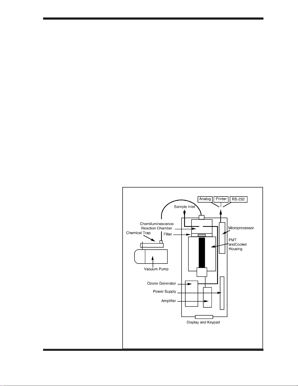
culture media, and other liquid samples. A schematic of the 280i NOA is shown in
Figure 1-1 and consists of the following major components:
• Sampling Inlet Systems
• Sample Flow Control Device
• Ozone Flow Control Module
• Ozone Generator
• Chemiluminescence Reaction Chamber and Optical Filter
• Photomultiplier Tube and Cooled Housing
• Vacuum Pump and Chemical Trap
• Front Panel Display
• Four Button Keypad
• PMT Amplifier
• Power Supply
• Analog to Digital Converter
• Microprocessor and Output Electronics
• Analog, Printer, and RS-232 Outputs
• Exhalation Pressure Transducer
• Optional Thermal Mass Flowmeter
Sample Inlet Systems
The NOA 280i has a
complete range of sample
inlet systems for
measurement of NO and its
reaction products including:
• Gas Sampling Kit for
measurement of gasphase NO. The kit
®
includes a Nafion
drier,
0.45 µm particle filter,
PVC sampling lines with
Luer® adapters and a
calibration tee.
Figure 1-1: Schematic of Model 280i Nitric
Oxide Analyzer
GE Analytical Instruments ©2006 DLM 14291 Rev. A
1-5
Page 20

• Purge vessel for the measurement of NO, nitrite, nitrate and other reaction
products in liquid samples. The purge vessel can also be used for headspace
analysis with a gas-tight syringe.
• Accurate NO™ Exhaled Breath Kit for on-line measurement of exhaled NO using
elevated pressure to close the soft pallet and constant low exhalation flow (30
– 250 mL/s BTPS)
• Bag Collection and Sampling Kit for off-line measurement of exhaled NO using
collection in Mylar® bags.
Sample Flow Control Device
The vacuum pump continuously draws gas into the analyzer at a constant flow
rate. A porous metal frit restrictor sealed in a 1/8" adapter is connected to a
Swagelok® bulkhead union at the rear of the NOA. The standard restrictor provides
a flow rate of ~200 mL/min and restrictors for other flow rates are available from
Sievers Instruments.
Ozone Flow Control Module
The connection for the gas supply for the ozone generator (oxygen or 95% O2/ 5%
CO2) is made using Teflon tubing and a Swagelok bulkhead connector. The gas
must be a regulated supply from an external cylinder, lecture bottle or house
oxygen. The flow rate of gas into the ozone generator (~30 mL/min) is controlled
using a regulator and small diameter tubing restrictors. The regulator and
bulkhead connectors are located on the back of the NOA. The regulator is adjusted
to 6 psi pressure, which is measured by a pressure transducer, and monitored on
the front panel display.
Ozone Generator
An electrostatic ozone generator and high voltage transformer are used to
generate ozone at a concentration of ~2% by volume from oxygen. This large
excess of ozone is sufficient for measurement of NO up to 500 ppm.
Chemiluminescent Reaction Chamber and Optical Filter
GE Analytical Instruments ©2006 DLM 14291 Rev. A
1-6
Page 21

Nitric oxide and ozone are mixed in a small volume (~20 mL) reaction cell. This
small volume permits measurement of low concentrations of NO at low flow rates
and produces sharp peaks for analysis of liquid samples. For maximum sensitivity,
the reaction cell is operated at low pressure (typically 4-7 torr). A few other
chemicals such as sulfur-containing compounds, undergo a chemiluminescent
reaction with ozone but emit light at shorter wavelengths. To minimize
interference from these species, an optical filter that transmits only red
wavelengths (>600 nm) is installed between the reaction cell and the
photomultiplier tube.
Photomultiplier Tube and Cooled Housing
The light from the chemiluminescent reaction of NO with O3 is measured using a
red-sensitive photomultiplier tube. For maximum sensitivity, the PMT is cooled to 12 °C using a thermoelectric cooled housing. The cooler is operated continuously
whenever the main power switch is on. The temperature of the cooled housing is
measured using a K-type thermocouple and monitored on the front panel display.
Vacuum Pump and Ozone Destruction Trap.
A vacuum pump is used to draw the sample into the NOA and maintain the reaction
cell at low pressure. The exhaust from the reaction cell exits the analyzer at the
rear of the instrument using a metal tube connected to Tygon tubing. Ozone in the
exhaust is removed using a chemical trap containing Hopcalite™. This material
reacts with ozone, removing it from the exhaust before the gas reaches the
vacuum pump. Since the Hopcalite is consumed, the chemical trap must be
periodically replaced. The oil used in the vacuum pump is a synthetic motor oil
(Mobil 1™ weight 10W-30) which provides better protection than conventional
pump oil. For long pump lifetime, the oil must be changed at regular intervals.
The exhaust from the pump contains some oil mist, which can be removed using a
charcoal trap. The microprocessor keeps track of the trap and oil lifetimes, and
notifies the user when it is time to replace the traps or change the oil.
Electronics
There are 7 circuit boards in the NOA:
GE Analytical Instruments ©2006 DLM 14291 Rev. A
1-7
Page 22

• PMT amplifier
• Analog to digital converter (ADC) board
• Microprocessor and Outputs board
• Power supply board
• 24 V power supply
• Front panel display
• Keypad.
The PMT amplifier processes the signal from the PMT. To provide both high
sensitivity and wide dynamic range, the amplifier has two gain ranges. High Gain is
used for measurements requiring high sensitivity (liquid samples and exhaled
breath). The amplifier in high gain has a linear response up to ~1 ppm of NO gas or
~400 picomoles of NO
-
or NO
2
-
for liquid samples. The low gain decreases the
3
sensitivity of the amplifier, permitting measurement of up to ~500 ppm of NO gas
or ~200 nanomoles of NO
-
or NO
2
-
for liquid samples. The analog output signal (mV
3
only) is obtained from the amplifier. A switch on the amplifier sets the full-scale
voltage. When the switch is in the down position the output range is 0–1V. When
the switch is in th eup position, the output range is 0–10V.
The amplifier is also connected to the ADC board which also monitors three
pressure transducers (cell, supply and exhalation), the cooler thermocouple and
the thermal mass flowmeter. The microprocessor and firmware calculate gas
concentration, monitor the performance of the analyzer, keep track of
maintenance items, and control the output of data. The power supply board and
24V power supply provides the high voltage for the PMT, power to the PMT cooler
and the DC power for the electronics. The front panel display and keypad are used
for display of the data and the operation of the analyzer.
Analog, Printer and RS-232 Outputs
In addition to displaying data on the front panel, data can also be: sent to a
recorder or integrator using the analog output, sent to a computer using the RS232 output, and printed using the parallel printer port. The analog output can be
set to 0-1 V or 0-10 V full-scale. The printer output shows the minimum, maximum
and average value for a selected print interval ranging from 5 seconds to 10
minutes. The RS-232 output provides data at sampling rates from 32 samples per
second to 6 samples per minute.
GE Analytical Instruments ©2006 DLM 14291 Rev. A
1-8
Page 23

Exhalation Pressure Transducer
An exhalation pressure transducer is present in the analyzer for use with the
Accurate NO breath kit and for detection of exhalations during breath-by-breath
measurements.
Thermal Mass Flow Meter
On-line measurement of exhalation flow rates can be performed using a optional
flow meter. The signal from the flow meter is included in the RS-232 output.
This completes the introduction to the NOA and its components:
• Chapter 2 lists the specifications of the analyzer.
• Chapter 3 has an overview of the firmware and controls.
• Chapter 4 contains the basic installation procedures.
• Chapter 5 contains the installation and setup for gas-phase measurements.
• Chapter 6 describes how to calibrate the NOA for gas-phase measurements.
• Chapter 7 describes on-line measurement of NO in exhaled breath.
• Chapter 8 describes off-line measurement of exhaled NO.
• Chapter 9 describes breath-by-breath and chamber sampling for exhaled NO
measurements.
• Chapter 10 describes measurement of nasal nitric oxide.
• Chapter 11 contains the installation and setup liquid measurement.
• Chapter 12 describes the setup and measurement of nitrite in liquid
samples.
• Chapter 13 describes the setup and measurement of nitrate in liquid
samples
• Chapter 14 describes the measurement of nitrosothiols and other reaction
products in liquid samples.
• Chapter 15 describes maintenance of the NOA.
• Chapter 16 lists troubleshooting procedures and error and warning
messages.
GE Analytical Instruments ©2006 DLM 14291 Rev. A
1-9
Page 24

Page 25

2. SPECIFICATIONS
Sensitivity
.................................................... Gas < 1 ppb
.................................................... Liquid ~1 picomole
Range
.................................................... Gas < 1 – 500,000 ppb
.................................................... Liquids nanomolar to millimolar
Response Time
.................................................... Electronics 67 msecs to 90% full
scale
.................................................... Lagtime 1 second
Repeatability
.................................................... Gas ± 5%
.................................................... Liquid ± 5 10%
Sample Size
.................................................... Gas 10 – 300 mL/min
.................................................... Liquid 0.001 – 5 mL
Display ........................................... Back-lit LCD screen
.................................................... ppb/ppm or mV
Outputs
.................................................... Analog 0 – 1V, 0 – 10 V
.................................................... Digital RS-232 (9600-38.4K baud)
.................................................... Printer parallel port
Data Sampling Rate............................ 0.002 - 32 samples/second
GE Analytical Instruments ©2006 DLM 14291 Rev. A
2-1
Page 26

Power Requirements................................120 V, 60 Hz (6A)
100 V, 50 or 60 Hz (7A)
230 V, 50 Hz (3A)
NOA
.........................................................Height 16 in. (41 cm)
.........................................................Width 6.2 in. (16 cm)
.........................................................Length 20 in. (51
cm) ....................................................
.........................................................Weight 35 lbs. (16
kg)
Vacuum Pump with installed trap
.........................................................Height 14.5 in. (37 cm)
.........................................................Width 7.5 in. (19 cm)
.........................................................Length 19 in. (48
cm)
.........................................................Weight 47 lbs. (21.5
kg)
Operating Environment
Ambient Temperature ....................................32°F to 86°F (0°C to 30°C)
Relative Humidity.......................................... 0% to 90%
Fuse Requirements
Main Fuse ...................................100 VAC model: T, 10A, 250V
120 VAC model: T, 5A, 250V
230 VAC model: T, 5A, 250V
Ozone Fuse..................................100VAC model: T, 200mA, 250V
120 VAC model: T, 200mA, 250V
230 VAC model: T, 100mA, 250V
GE Analytical Instruments ©2006 DLM 14291 Rev. A
2-2
Page 27
3. MENUS AND CONTROL OVERVIEW
Operation of the NOA 280i is performed using the four front panel buttons (UP
Arrow, DOWN Arrow, ENTER, and CLEAR) to run the menu-based firmware. Use
the UP or DOWN Arrow buttons to scroll through the menu options and select
values. The ENTER Button is used to select menu options and to save setpoints.
The CLEAR Button is used to exit menus and clear entries. The CLEAR Button is
also used to display the Status Menu from the Main Menu, select the Main Menu
from the Measurement Menu or to return to the Measurement Menu from the
Main Menu. A cursor is used for selection of the menu options and the location
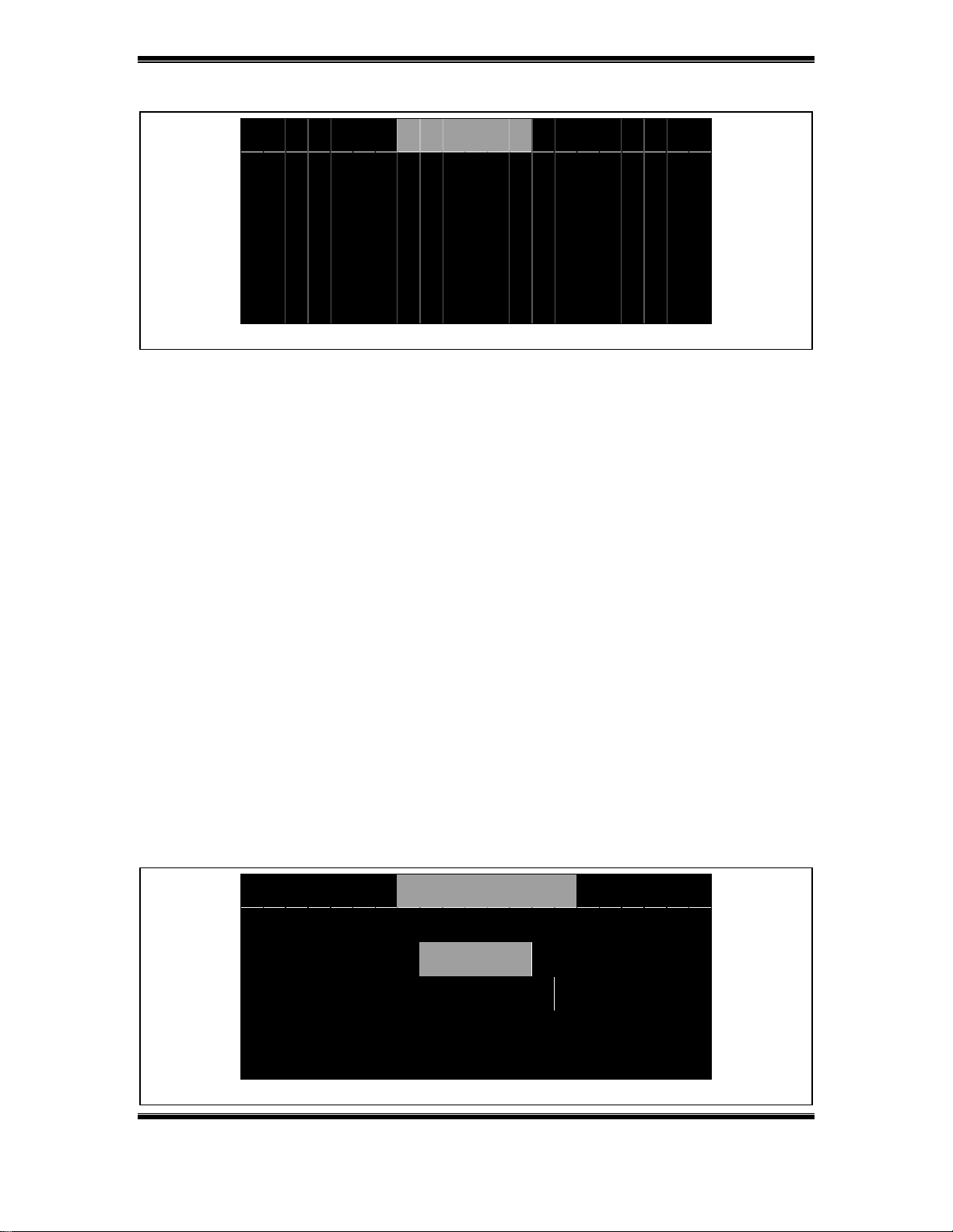
M A I N M E N U
A N A L Y S I S C A L I B R A T I O N
C O N T R O L M E S S A G E S
0 4 J U L 0 0 0 8 : 1 7 : 3 1
of the cursor is indicated by a highlighted menu option.
Main Menu
There are five options in the Main Menu: Analysis, Control,, Calibration,,
Messages, and Maintenance,. A title field is located at the top of the menu, and
the date and time are displayed in the message line at the bottom of the
display. Select an option by using the Arrow buttons to highlight the desired
M A I N T E N A N C E
Figure 3-1: Main Menu
option, and press the ENTER button.
Status Screen
Press the CLEAR button from the Main Menu to display the Status Screen. This
screen shows the current values for the PMT cooler temperature, reaction cell
GE Analytical Instruments ©2006 DLM 14291 Rev. A
3-1
Page 28
ff)
S T A T U S
C O O L E R T E M P – 1 2 . 0 ° C
C E L L P 7 6 0 . 0 T o r r
S U P P L Y P 0 . 0 P S I G
P M T S I G N A L 0
E N T E R / C L E A R c o n t i n u e
Figure 3-2: Status Screen (PMT O
pressure, oxygen supply to the ozone generator, and the PMT signal, (counts at
analog to digital converter). Before starting the NOA, the status screen should
be checked to confirm that the cooler temperature, cell and supply pressures
are within the specifications required for the start-up tests.
Pressing either the ENTER or CLEAR button will return to the Main Menu.
Analysis
The Analysis option is used to start and stop the NOA. The NOA has three modes
.
of operation: Start, Stand-by and Stop. From the Main Menu, pressing the
ENTER button with the Analysis option highlighted will display the Analysis
Menu.
Selecting the Start option will:
• Switch to the Startup Screen.
• Check the cell pressure to see if it is above 300 torr, then turn on the
pump.
A N A L Y S I S
S T A R T
S T A N D - B Y
Figure 3-3: Analysis Menu with NOA in Stop Mode.
GE Analytical Instruments ©2006 DLM 14291 Rev. A
3-2
Page 29
V A C U U M P U M P P A S S
C O O L E R T E M P P A S S
C E L L P R E S S P A S S
S U P P L Y P R E S S T E S T I N G
P M T S I G N A L
E N T = S T A T U S C L R = S T O P
Figure 3-4: Start-up Screen.
• Check the PMT cooler temperature to see if it is –12 ± 2 °C.
• Wait until the reaction cell pressure is < 100 torr.
• Check the ozone supply pressure is >4 psig (6 psig recommended).
• Turn on the PMT and record an ozone-off baseline signal.
• Turn on the ozone generator, and wait for an increase in the PMT signal
due to the background chemiluminescence from ozone.
• Display the PMT signal in the Measurement Display.
If any of the above conditions are not met, the start-up screen will FAILED for
that test. Pressing ENTER from the Start-up Screen will display the Status
Screen to aid in troubleshooting failed tests. Pressing CLEAR will return to the
Analysis Menu.
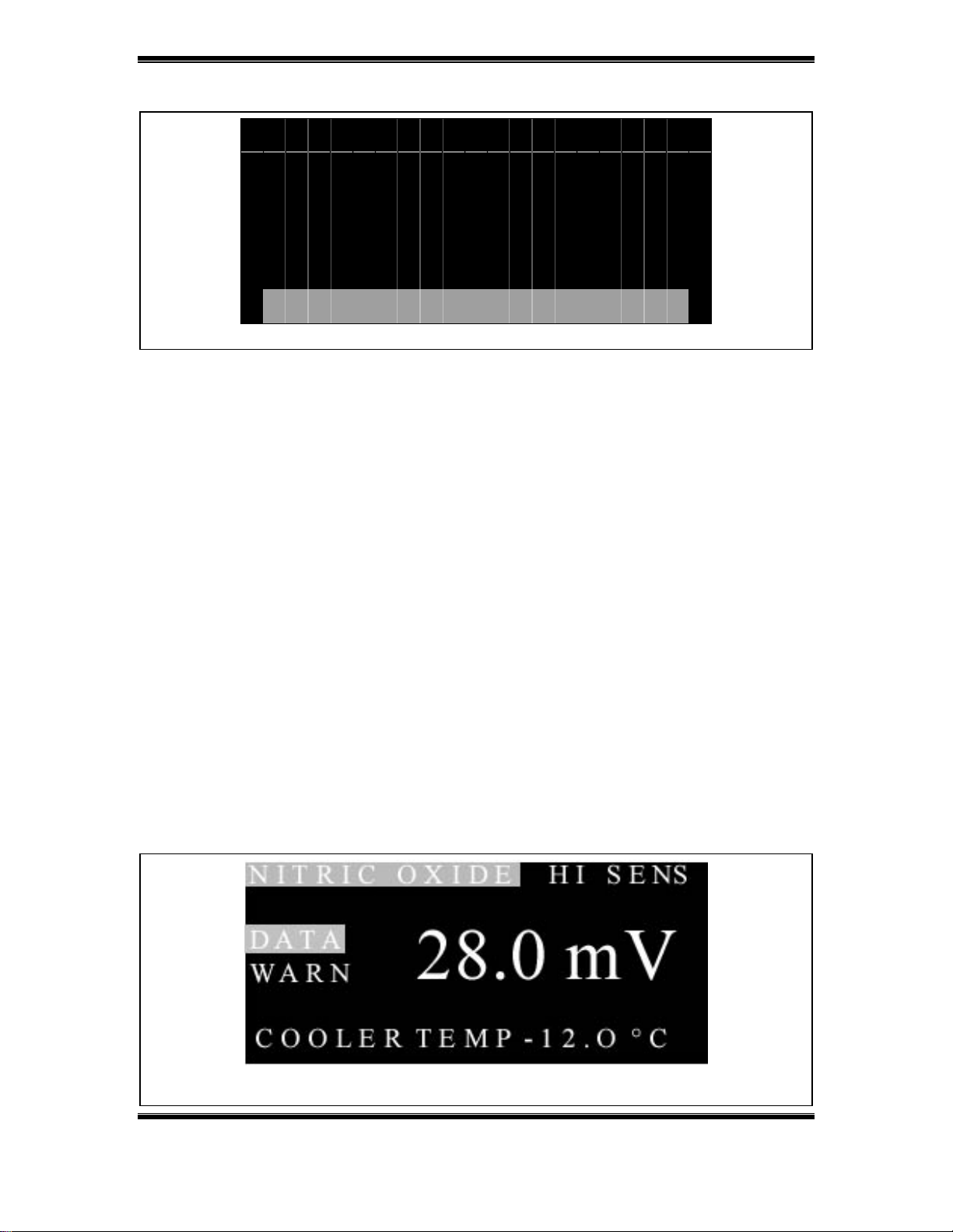
Measurement Menu
Once the start-up testing is completed, the Measurement Menu is displayed.
Figure 3-5:Measurement Menu (Nitric Oxide Mode)
GE Analytical Instruments ©2006 DLM 14291 Rev. A
3-3
Page 30
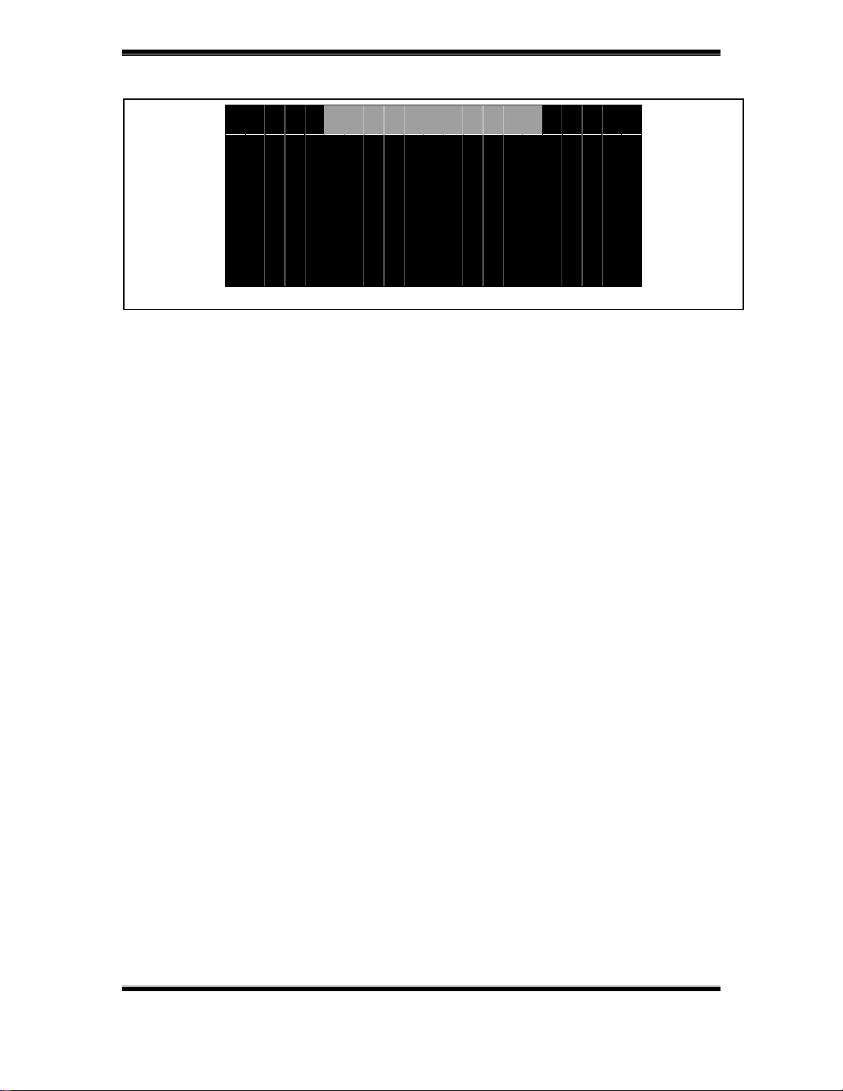
D A T A O U T P U T
O U T P U T E N A B L E D
E N T E R t o g g l e o u t p u t
Figure 3-6: Data Output Menu.
This menu shows that NOA’s mode (Nitric Oxide or Exhalation), the PMT
amplifier’s setting (HI or LO sensitivity) and the signal from the PMT (mV or
gas concentration). Two shortcuts are available from the Measurement Menu;
DATA and WARN. When DATA is highlighted, pressing the ENTER button moves
to the Data Output Menu. The data output (Com port and printer) are enabled
at start-up, but can be disabled to pause data collection by pressing the ENTER
button. The outputs are re-enabled by pressing the ENTER button. Pressing
CLEAR returns to the Measurement Menu.
The firmware keeps track of usage and when maintenance is required, a WARN
shortcut is displayed in the Measurement Menu. The UP or DOWN Arrow buttons
can be used to scroll between DATA and WARN. With the WARN shortcut
highlighted, pressing the ENTER button will display the Warning Menu with a
list of the current warnings (see Chapter 14 for information on maintenance
and warnings).
In the Nitric Oxide mode the current values for the cooler temperature, cell
pressure and ozone supply pressure are displayed at the bottom of the
Measurement Menu. In the Exhalation mode, a bar graph of the exhalation
pressure is displayed.
From the Measurement Menu, pressing the CLEAR button will return to the Main
Menu and from the Main Menu, pressing CLEAR will return to the Measurement
Menu.
GE Analytical Instruments ©2006 DLM 14291 Rev. A
3-4
Page 31

When the NOA is in the Start mode, selecting Analysis from the Main Menu will
display two options; Stand-by and Stop.
The Stand-by option is always available from the Analysis Menu. If the analysis
has been started, selecting the Stand-by option will turn off the PMT and ozone
generator, but leave the vacuum pump on. If the analysis was stopped,
selecting the Stand-by option will turn on the vacuum pump.
GE Analytical Instruments ©2006 DLM 14291 Rev. A
3-5
Page 32

A N A L Y S I S
S T O P
S T A N D - B Y
Figure 3-7: Analysis Menu (NOA in Start Mode).
When the NOA is in the start mode, selecting Stop will:
• Display a confirmation screen “Are you sure? continue / stop”
• If the Stop option is selected, turn off the PMT, and ozone generator.
• Run the vacuum pump for 2 minutes to clear residual ozone from the
system.
• Turn off the vacuum pump.
Main Menu Options
The other options from the Main Menu are used to configure the NOA for the
different applications, perform the calibration for gas-phase measurements,
view warnings and errors, and view and install consumables.
Control
The Control Menu is used to setup the NOA for liquid or gas-phase
measurements, set the output intervals and the sensitivity of the NOA. The
setup can be stored as a method to permit easy switching between
applications. The Control Menu also permits viewing of the cooler temperature
C O N T R O L
M E T H O D
S E T U P
S T A T U S
Figure 3-8: Control Menu.
GE Analytical Instruments ©2006 DLM 14291 Rev. A
3-6
Page 33

and pressure via the Status Screen.
Calibration
C A L I B R A T I O N
C A L I B R A T E
V I E W
P R I N T
Figure 3-9: Calibration Menu.
The Calibration Menu is used to perform the calibrations for gas-phase
measurements and can be used to view and print the gas and pressure
transducer calibration values.
Messages
The Messages Menu is used to view warnings and errors. Warnings indicate that
maintenance is required and a WARN shortcut is displayed in the Measurement
M E S S A G E S
W A R N I N G S
E R R O R S
Figure 3-10: Messages Menu.
Menu. Errors indicate that the cooler temperature or the supply or cell
pressures are out of range. When an error is detected, the NOA is placed in the
Stop Mode and the firmware switches to the Errors menu.
GE Analytical Instruments ©2006 DLM 14291 Rev. A
3-7
Page 34

Maintenance
The Maintenance Menu is used to setup the security, view and install
consumable and delete old warnings and errors.
M A I N T E N A N C E
C O N S U M A B L E S
D E L E T E WA R N & E R R
S E C U R I T Y
Figure 3-11: Maintenance Menu.
Time-out Function
The NOA’s firmware monitors keyboard activity and if no button pushes are
detected for 10 minutes, the firmware will return to the Main Menu, if the NOA
is in the Stop or Standby Mode or the Measurement Menu if the NOA is in the
Start Mode.
GE Analytical Instruments ©2006 DLM 14291 Rev. A
3-8
Page 35

4. INSTALLATION
Location
Place the analyzer on a clean, unobstructed surface approximately 25" (60 cm)
deep by 6.2" (16 cm) wide that can support at least 35 pounds (16 kg) in addition
to existing equipment. For proper heat dissipation, ensure that an additional 6" (16
cm) is available at the rear and on both sides of the detector. Leave ~ 24" (60 cm)
of additional space on one side of the detector for the purge vessel. Additional
space will be required for computers, printers and integrators.
Place the vacuum pump on a space of nearby floor or bench 7.5" (19 cm) by 19" (48
cm) with a minimum height clearance of 14.5" (37 cm). Pump weight is 47 lbs.
(21.5 kg).
The analyzer and pump can also be placed on a cart for mobile operation. The cart
should have a bottom shelf with enough clearance for the vacuum pump and
should be sturdy enough to support the total weight of the analyzer and pump (82
lbs. 38 kg), plus any additional equipment or gas cylinders that will be placed on
the cart.
Power Requirements
The detector and vacuum pump are powered from a standard, 15 amp, 120 VAC 60
Hz grounded AC outlet. The NOA and pump will draw ~6 amps in normal operation,
and slightly higher instantaneous current with the pump running.
For 230 VAC versions of the detector, a standard (230 VAC, 50 Hz) grounded AC
outlet (~3 amps) is required.
For 100 VAC versions, a standard (100 VAC, 50 or 60 Hz) grounded AC outlet (~7
amps) is required.
GE Analytical Instruments ©2006 DLM 14291 Rev. A
4-1
Page 36

Environmental Considerations
Operate the NOA 280 in an environment comfortable for human habitation with
reasonably constant temperature and humidity. Avoid elevated temperatures;
operating at temperatures greater than 85° F (30° C) may cause problems with the
LCD display and the PMT cooler..
Tools and Additional Supplies
The following items will be needed to install and operate the NOA 280:
Tools
The following tools will be required for all applications:
• Open End Wrenches - 1/4", 5/16", 7/16", 1/2", 9/16", 13/16" and 7/8"
(Adjustable wrenches can also be used)
• Adjustable wrench or 11/8" open-end wrench is required for
connecting regulators to gas cylinders.
• Phillips-head Screw Driver
• Hexdriver or regular screwdriver
Gases
A cylinder of oxygen or 95% oxygen, 5% CO2 equipped with a two stage regulator
is required for the ozone generator. House oxygen and a flow controller may
also be used. If oxygen is not available, air can be used, however, the NOA will
need to recalibrated for gas measurements if air is used for the ozone
generator.
Data Collection
A computer (PC or Macintosh) is required for collection of data using the RS-232
output. For PCs, a Pentium is required. For Mac’s a PowerPC is required. The
computers should have at least 32 megabytes of RAM. For computers without a
internal serial port, a USB-Serial adapter is required.
For real-time display of the analog signal, a strip chart recorder or integrator
may be used. The analog signal can also be sent to a computer using an analog-
GE Analytical Instruments ©2006 DLM 14291 Rev. A
4-2
Page 37

to-digital converter. For the printer output, any Centronics® style printer can
be used. Contact Sievers Instruments with any questions regarding data
collection equipment.
GE Analytical Instruments ©2006 DLM 14291 Rev. A
4-3
Page 38

Pump
Oil Fill Caps
Pump Outlet
Power Switch
Oil Return/Gas Ballast
Oil Level
Sight Glass
Drain Plug
Figure 4-1: Schematic of RV 3 Pump.
Vacuum Pump Setup
Open the vacuum pump box and remove the pump, pump oil (Edwards Ultra
Grade), and the power cord. The accessories kit (pump fittings, Tygon tubing, hose
clamps and mounting bracket) is shipped in a separate box.
Step 1 – Add Oil to the pump
Remove one of the two oil fill plugs from the top of the pump (see Figure 4-1) and
add oil until the oil level just reaches the MAX mark on the pump at the top of the
sight-glass (DO NOT OVERFILL !).
Step 2 - Install Pump Inlet Fitting
Remove the plastic caps from inlet and outlet of the pump. Locate the barbed
inlet fitting and clamp in the pump accessories kit. Place the barbed fitting on the
GE Analytical Instruments ©2006 DLM 14291 Rev. A
4-4
Page 39

t
g
o-ring on the pump inlet. Place the clamp over the inlet fitting, o-ring and barbed
fitting and secure with the screw and wing nut finger-tight.
Step 3- Install the Chemical Trap Mounting Bracket
Locate the Allen wrench, black Allen screws and trap mounting bracket in the
pump accessories kit. Use the Allen wrench to remove the two screws on the rear
of the top plate of the pump. Insert the black Allen screws through the holes in
the bracket and connect to the pump with bracket’s clip on the same side as the
pump inlet (Figure 4-2).
Locate the Hopcalite trap in the NOA accessories box and the short length of clear
Mounting Bracke
for Charcaol Trap
Hopcalite Trap
Charcoal Trap
Fi
ure 4-2: RV3 Pump with Chemical and Charcoal Traps.
GE Analytical Instruments ©2006 DLM 14291 Rev. A
4-5
Page 40

Tygon tubing and two hose clamps in the pump accessories kit. Place the hose
clamps over the tubing, and connect one end of the tubing to the pump inlet
barbed fitting and the other end to the barbed fitting on the elbow of the
chemical trap. Use a 5/16” hexdriver or a regular screwdriver to tighten the hose
clamps.
Step 4 - Install the Pump Outlet Fitting
The RV3 pump can be equipped with either a charcoal filter to remove oil mist
from the pump exhaust or a barbed outlet fitting for connecting tubing to the
pump exhaust for venting to a fume hood or house vacuum.
Place the centering o-ring on the pump outlet fitting, place the barbed fitting on
the o-ring. Place the clamp over the outlet fitting, o-ring and barbed fitting and
secure with the screw and wing nut. If the charcoal trap is not used, connect a
length of Tygon tubing over the barbed outlet fitting and place the other end of
the tubing in a fume hood.
To install the charcoal trap, locate the Allen wrench and mounting bracket in the
charcoal trap kit. Use the Allen wrench to remove the two screws on the front of
the top plate of the pump. Insert the screws through the holes in the bracket and
connect to the pump with bracket’s clip on the same side as the pump outlet
(Figure 4-2). Locate the charcoal trap, the short length of clear Tygon tubing and
two hose clamps. The charcoal trap is shorter than the Hopcalite trap used on the
pump inlet. Place the hose clamps over the tubing, and connect one end of the
tubing to the pump outlet barbed fitting and the other end to the barbed fitting on
the elbow of the charcoal trap. Use a 5/16” hexdriver or a regular screwdriver to
tighten the hose clamps.
Step 5 - Install the Chemical Trap and Vacuum Hoses
Place a hose clamp over the end of the vacuum hose (Tygon tubing with black heat
shrink and a metal fitting on one end), and connect the hose to the barbed fitting
GE Analytical Instruments ©2006 DLM 14291 Rev. A
4-6
Page 41

on the straight end of the Hopcalite trap. Use a 5/16” hexdriver or a regular
screwdriver to tighten the hose clamp.
GE Analytical Instruments ©2006 DLM 14291 Rev. A
4-7
Page 42

gure
3: NOA Back Panel
.
Fi
4-
GE Analytical Instruments ©2006 DLM 14291 Rev. A
4-8
Page 43

Step 6 - Connect Power Cord to Vacuum Pump and Turn On Pump Power Switch
Locate the pump power cord and connect one end to the power cord inlet on the
side of the pump. Turn the pump power switch on the other side of the pump to
the ON position.
Connections to NOA
All of the connections for gases, the vacuum pump and outputs are at the back of
the NOA (Figure 4-3). Place the NOA on a bench in a position so there is access to
the back of the analyzer. Connect the power cord to the analyzer and plug the
cord into an AC Outlet.
Vacuum Pump Power Cord and Vacuum Hose
Plug the female plug on the power cord from the vacuum pump into the socket
labeled “Vacuum Pump” on the back of the NOA. In the center of the back panel is
a protective cap on the exhaust of the NOA. The cap protects the photomultiplier
tube from exposure to light during shipping and anytime the vacuum hose is
removed from the analyzer.
Remove the protective cap from the exhaust port of the NOA. Anytime the vacuum
hose is removed from the NOA this cap should be replaced. Carefully thread the
1/2" Swagelok nut on the vacuum hose to the exhaust fitting. Place a 13/16"
wrench on the fitting on the NOA and use a 7/8" wrench to fully tighten
the nut.
This will require some force to get a good seal.
Vacuum Test
Once the vacuum pump has been connected, test that all connections are tight by
performing a vacuum test. Make sure the power switch on the vacuum pump is in
GE Analytical Instruments ©2006 DLM 14291 Rev. A
4-9
Page 44

the ON position and the protective caps are on the sample and oxygen inlets. To
perform the test:
• Use a 7/16" wrench to tighten the protective caps on the sample inlet and
ozone supplies.
• Turn on the Main Power switch located at the rear of the NOA.
• With the Analysis option highlighted, press the ENTER Button to display the
Analysis Menu.
• Use the Down Arrow Button to scroll to Stand-by and press ENTER. The vacuum
pump will start.
• Allow the pump to operate for ~10 minutes and record the reaction cell
pressure by selecting the Control option from the Main Menu and pressing the
ENTER Button.
• From the Control Menu, use the Down Arrow Button to scroll to Status and
press ENTER. The cell pressure will be displayed.
Reaction Cell Pressure Vacuum Test _____________________ torr
If the vacuum pump connections are tight, the reaction cell pressure should
decrease to 1-2 torr within 10 minutes. If the pressure decreases to <2 torr, the
connections are tight.
If the pressure is higher check the connections to the vacuum pump, retighten the
hose clamps and the connection of the vacuum pump to the back of the analyzer.
If the pressure remains above 1-2 torr after retightening the connection, contact
Sievers Instruments, Inc. at (303) 444-2009 for assistance.
After completing the vacuum test, turn the vacuum pump off by pressing CLEAR to
return to the Main Menu, scroll to Analysis and press ENTER and select Stop and
press ENTER. The display will change with Continue and Stop options. Select Stop
to turn off the vacuum pump.
Leave the main power switch ON while completing the installation to cool the
PMT.
GE Analytical Instruments ©2006 DLM 14291 Rev. A
4-10
Page 45

Gas for Ozone Generator
The NOA requires oxygen for the ozone generator. The connection to the NOA is
made via a 1/8" Swagelok bulkhead in the back panel, just above the vacuum
pump plug. If oxygen is supplied from a gas cylinder, the cylinder must be
equipped with a two-stage regulator with a shutoff valve on the outlet and an
adapter for connection of 1/8" tubing with Swagelok-brand connections. A 1/4"
female NPT to 1/8" Swagelok union and a 1/4" male NPT to 1/8" Swagelok union
are provided with the analyzer. Wrap Teflon tape on the outlet of the shutoff
valve or the male NPT union to prevent leaks on the NPT connection.
A 6 ft length of 1/8" OD Teflon tubing with brass nuts and ferrules is supplied with
the NOA for connecting the oxygen supply to the bulkhead fitting on the NOA back
panel. Use a 7/16" wrench to remove the protective cap from the bulkhead fitting
“Oxygen Inlet” on the back panel. Connect the Teflon tubing to the bulkhead fitting.
Connect the other end of the tubing to the adapter on the regulator. Use a 7/16"
wrench to tighten the nuts 1/4 turn past finger tight. Turn on the main valve on
the oxygen tank and adjust the outlet pressure on the regulator to 10 psig (~700
mBar, 520 torr or 0.7 kg/cm2).
The flow of gas through the ozone generator is ~30 mL/min and is controlled by a
pressure regulator located on the back panel of the NOA. The black knob on the
regulator has two positions; locked and adjust. When pulled out away from the
back panel, the knob can be turned to adjust the ozone gas pressure, when pushed
in toward the back panel, the knob will be locked and the knob will not turn. To
set the pressure, from the NOA Main Menu, press CLEAR to display the Status
Screen. Adjust the regulator until the Supply Pressure is 6.0 ± 0.2 psig (419 mBar,
2
314 torr or 0.4 kg/cm
) .
Oxygen can also be supplied from an E size cylinder or house oxygen. Normally
these are equipped with flow controllers instead of a pressure regulator. Oxygen
tubing with 22 mm connectors, universal oxygen tubing or bubble tubing can be
used to connect the barbed connector of the flow controller to the NOA. In the
GE Analytical Instruments ©2006 DLM 14291 Rev. A
4-11
Page 46

accessories kit is a brass 1/8” Swagelok to barbed adapter. Remove the cap from
the oxygen inlet at the back of the NOA and attach the barbed adapter. Use a
7/16” wrench to tighten the nut 1/4 turn past finger tight. Connect one end of the
oxygen tubing to the barbed adapter on the NOA and the other end to the barbed
adapter on the oxygen tank or house supply. Since the flow through the ozone
generator is only 30 mL/min, a low-flow flow controller should be used and the
flow rate adjusted to the lowest flow possible. If the flow is set too high, the
tubing will come off the barbed adapters! Hose clamps can be used to help
secure the tubing. Turn on the oxygen, press CLEAR to view the Supply Pressure
and adjust the NOA’s regulator to 6 psig. If the controller cannot be set to a low
enough flow, a pinhole in the oxygen tubing will prevent the tubing from coming
off of the barbed adapters.
Frit Restrictor
The flow into the NOA is controlled by a metal-frit restrictor in an adapter attached to
the Sample Inlet bulkhead fitting on the back panel of the NOA (Figure 4-3). The
standard restrictor has a flow rate of ~200 mL/min and restrictors with other flow
rates are available. Remove the protective cap and locate the frit restrictor (stainless
steel 1/8” male/female adapter in the accessories kit). Connect the restrictor to the
bulkhead fitting labeled Sample Inlet and use a 7/16” wrench to tighten the nut 1/4
turn past fingertight.
Computer, Printer and Analog Signal Connections
The connections for the computer, printer and analog signal are at the back of the
NOA.
Computer – the RS-232 connector is the 9 pin connector near the top of the back
panel. Two cables are available for connecting the NOA to PCs and Macs. The
cable for PCs is a 9 pin male/9 pin female cable (ACH 09010). Connect the male
end to the NOA and secure with the thumbscrews. Connect the 9 pin female end to
the computer’s COM Port. Some desktop PCs have 25 pin Com Ports and require a 9
GE Analytical Instruments ©2006 DLM 14291 Rev. A
4-12
Page 47

M
M
M
↓
pin to 25 pin Serial adapter for use with the
NOA. These adapters are available from most
computer stores. For Apple computers, the
cable is a 9 pin male to 8 pin DIM (ACH 14000).
Connect the 9 pin male end to the NOA port
and secure with a screwdriver. Connect the DIM
end to either the printer or modem port on the
Macintosh. Newer Macs do not have serial ports
and either a USB to serial adapter or a serial
port card is required. Contact Sievers
Instruments for more information on these
devices.
Printer – a Centronics 25 pin printer connector
is located below the RS-232. The NOA can be
connected to any 80 column printer using the
cable that came with the printer.
Analog Output – the analog signal from the NOA
is the BNC connector to the right of the RS-232
output. This is a 0-1V output directly from the
PMT amplifier and can be set to a 0-10V output
using a switch on the amplifier. A cable (ASM
00165) with a BNC connector and spade lugs is
available from Sievers Instruments
Setting the Clock
To set the clock on the NOA:
• From the Main Menu use the Arrow buttons
to scroll to Control and press ENTER to
display the Control Menu.
A I N ME N U
ANA L Y S I S C A L I B R A T I ON
C ON T RO L ME S S A G E S
A I N T E N A N C E
0 4 J U L 0 0 1 2 : 3 4 : 5 6
C HA N G E S E T U P
AN A L Y S I S
C ON F I G U R A T I O N
C ON F I G U R A T I O N
C O M P O R T
P R E S S U N I T S
DA T E & T I ME
C U R R E N T D A T E & T IME
0 4 J U L 0 0 0 8 : 0 8 : 4 2
s e l e c t f i e l d
↑
E N T c h a n g e C L R e s c a p e
C U R R E N T D A T E & T IME
0 4 J U L 0 0 1 0 : 0 8 : 4 2
s c r o l l d a t e / t i m e
↓ ↑
E N T a c c e p t C L R r e j e c t
C O N T R O L
E T H O D
S E T U P
S T A T U S
S E T U P
C H A N G E
V I E W
P R I N T
L O G I N
O P E R A T O R
S I E V E R S
GE Analytical Instruments ©2006 DLM 14291 Rev. A
4-13
Page 48

• Use the Down Arrow to scroll to Setup and press ENTER to display the Setup
Menu.
• Select the Change option and press ENTER to display the Login Menu.
• Select Operator and press ENTER to display the Change Setup Menu.
• Scroll to Configuration and press ENTER.
• Scroll to DATE and TIME and press ENTER.
• To change the time, use the Down Arrow button to scroll to the hour field and
press ENTER.
• Use the Arrow buttons to scroll to the current hour and press ENTER to save.
• To change the minutes, use the Down Arrow button to scroll to this field, press
ENTER, then use the Arrow buttons to change the minutes and press ENTER to
save.
• After setting the time, press CLEAR to return to the Configuration Menu.
Configuration Menu Options
The Configuration Menu contains two other menu options: Com Port and Pressure
Units. These options, along with the clock, and only be changed when the NOA is
in the Stop or Standby mode.
Com Port
The Com Port option is used to set the baud rate for communications with the
computer, with a default setting of 38400. This rate should be used for all
application unless, the computer used for data acquisition cannot be used at this
baud rate. Lower baud rates will limit the Com port intervals that can be used. At
19200 or 9600, the 1/32 interval cannot be used and some data loss may be
observed at an interval of 1/16.
GE Analytical Instruments ©2006 DLM 14291 Rev. A
4-14
Page 49

M
M
M
To change the Baud Rate:
• From the Configuration Menu select Com
Port.
• Select Baud Rate and use the Arrow buttons
to scroll to the desired rate.
• Press ENTER to display the Confirmation
screen (not shown) and press ENTER to save
the new rate. Press CLEAR to return to the
Configuration Menu.
Pressure Units
The units for the cell and supply pressures
shown in the Status menu and in the
Measurement Menu for the Nitric Oxide Mode
can be changed using the Press Units option.
The default units are Torr (mm Hg) for the cell
pressure and PSIG (pounds per square inch
gauge) for the supply pressure.
To change the Cell Pressure Units:
• From the Configuration Menu, select Press
Units and press Enter to display the
Pressure Units Setup Menu.
• Select Cell Pressure and press ENTER.
• From the Cell Press Units Menu, use the
Arrow buttons to scroll to the desired units,
press Enter and when the confirmation
screen is shown, press ENTER to save the
C ON F I G U R A T I O N
C O M P O R T
P R E S S U N I T S
DA T E & T I ME
P R E S S U N I T S S E T U P
S U P P L Y P R E S S
C E L L P R E S S U N I T S
c u r r e n t : T o r r ( m mH g )
C ON F I G U R A T I O N
P R E S S U N I T S S E T U P
S U P P L Y P R E S S
O 3 S U P P L Y P R E S S UN I T S
C OMP O R T S E T U P
mB a r P S I G
T o r r k g / c m 2
c u r r e n t : P S I G
ANA L Y S I S C A L I B R A T I ON
C ON T RO L ME S S A G E S
0 4 J U L 0 0 1 2 : 3 4 : 5 6
c u r r e n t : 3 8 4 0 0
D E L E T E WA R N & E R R
C E L L P R E S S
m B a r
T o r r
C O M P O R T
C E L L P R E S S
P R E S S U N I T S
DA T E & T I ME
B A U D R A T E
A I N ME N U
B A U D R A T E
9 6 0 0
1 9 2 0 0
A I N T E N A N C E
3 8 4 0 0
A I N T E A N C E
S E C U R I T Y
C ON S U MA B L E S
C ON S U MA B L E S
V I E W
I N S T A L L
new units.
GE Analytical Instruments ©2006 DLM 14291 Rev. A
4-15
Page 50

To change the Supply Pressure Units
• From the Pressure Units Setup Menu, select
Supply Press.
• From the O3 Supply Press Units Menu, use
the Arrow buttons to scroll to the desired
units and press ENTER.
• From the Confirmation Screen, press ENTER
to save the new units.
• Press CLEAR five times to return to the Main
Menu.
Setting the Consumables Installation Data
To set the installation dates:
I N S T A L L
P UMP O I L
HO P C A L I T E
C E L L
C OO L E R
P UMP O I L
I N S TA L L E D 0 6 J U N 0 0
d a y s h o u r s
I N I T I A L 3 7 1 2
R EMA I N I NG 3 7 1 0
E N T i n s t a l L C L R e s c
P UMP O I L
DO N O T I N S T A L L
I N S T A L L
P UMP O I L
I N S TA L L E D 0 4 J U L 0 0
d a y s h o u r s
I N I T I A L 3 7 1 2
R EMA I N I NG 3 7 1 2
I N S TA L L A T I O N A C C E P T E D
• From the Main Menu, select Maintenance.
• From the Maintenance Menu, select Consumables.
• From the Consumables Menu select Install.
• From the Install Menu, select Pump Oil.
• From the Pump Oil Menu, press ENTER, scroll to Install and press ENTER. The
Pump Oil Menu will indicate that the installation was accepted and then return
to the Install Menu.
• Repeat the installation process for the Hopcalite, Cell and Cooler by selecting
each item from the Install menu, pressing ENTER, then selecting Install.
Start-up
GE Analytical Instruments ©2006 DLM 14291 Rev. A
4-16
Page 51

This completes the initial setup of the NOA. Instructions for installing the purge
vessel for liquid samples are in Chapters 1012. Instructions for installation of the
gas-sampling package are in Chapter 5 and instructions for assembly of the exhaled
breath accessories are in Chapters 79. Before continuing with the installation,
start the NOA to verify proper operation.
To Start the NOA:
• From the Main Menu, press CLEAR to display the Status Screen.
• Verify that the Cooler Temperature is –12 ± 0.2 °C, the Supply Pressure is 6 ±
0.2 psig and the Cell Pressure is > 300 torr.
• Press ENTER or CLEAR to return to the Main Menu.
• With the Analysis option highlighted, press ENTER.
• From the Analysis Menu, select Start.
The Startup screen is displayed and the NOA should pass all tests and display the
Measurement Menu. If the NOA fails any tests, consult the Troubleshooting section
(Chapter 14) for assistance.
GE Analytical Instruments ©2006 DLM 14291 Rev. A
4-17
Page 52

Page 53

5. INSTALLATION AND SETUP: GAS-PHASE MEASUREMENTS
Installation of Gas Sampling Package
The gas sampling package is used for all gas-phase NO measurements. It includes a
Nafion drier, a white 0.45 µm Teflon filter, a 6 ft PVC sampling line with male Luer
adapters, a bacterial filter, a 6 ft PVC pressure line with white male Luer
adapters, a calibration tee, tubing clamp and a male Luer cap.
To install the gas sampling package:
• Connect the 1/8" Swagelok nut on the Nafion drier (tubing with outer mesh) to
the frit restrictor on the sample inlet on the NOA's back panel. It is not
necessary to use a wrench to tighten the nut, finger-tight is acceptable.
• Connect the white Teflon filter to the female Luer fitting on the Nafion drier.
• Connect the NO sample line (clear PVC tubing without the white Luer fittings)
to the Teflon filter.
• Connect the bacterial filter to the Luer bulkhead fitting labeled “Breath
Pressure” on the NOA back panel.
• Connect the Pressure line (clear PVC tubing with white Luer adapters on ends)
to the bacterial filter.
GE Analytical Instruments ©2006 DLM 14291 Rev. A
5-1
Page 54

• The Luer tee is used for calibration only. If the Calibration Kit was ordered, the
tee is installed on the outlet of the NO calibration regulator.
• The clamp is used to securing the sampling and pressure tubing when not in
use. Remove the adhesive backing and secure the clamp to the upper left-hand
side at the rear of the NOA’s top cover, near the sample inlet.
Installation of Thermal Mass Flowmeter
For on-line measurement of exhaled NO, the subject’s exhalation flow rate can be
measured using the optional Thermal Mass Flowmeter. To install the flowmeter:
• Locate the flow meter cable with 8 pin mini-DIN connectors on both ends. On
the connector is a small positioning arrow.
• Hold the connector with the positioning arrow on top and plug the cable into
the Flowmeter connector on the NOA’s back panel (see Figure 4-3).
• Hold the flowmeter with the serial number tag facing up and adjust the end of
the cable so that the positioning arrow is on top and plug the cable into the
flowmeter.
• Remove the phillips-head screw from the front, middle position on the NOA’s
left side cover.
• Locate the metal flow meter clamp and phillips-head screw from the flow
meter kit and install the clamp on the NOA’s side panel.
Figure 5-1: Gas Sampling Package
GE Analytical Instruments ©2006 DLM 14291 Rev. A
5-2
Page 55

• Install the flow meter in the clamp.
• Locate the plastic cable clamp for the flowmeter cable.
• Remove the adhesive backing and secure the cable clamp to the NOA’s top
cover, near the back (below the gas sampling clamp).
• Secure the flow meter cable using the clamp.
GE Analytical Instruments ©2006 DLM 14291 Rev. A
5-3
Page 56

M
M
M
M
M
NOA Setup for Gas-Phase Measurements
Gas-phase NO can be measured using either the Nitric Oxide or Exhalation Modes.
In the exhalation mode, the NOA outputs the
signal from the breath pressure transducer and
the thermal mass flowmeter. The Exhalation
Mode must be used for on-line and breath-bybreath NO measurements. The Nitric Oxide
Mode is used for measurements that do not
require the flowmeter or breath pressure such
as off-line exhaled NO measurements.
Exhalation Mode
To setup the NOA for the exhalation mode
(press ENTER to select Menu Option):
• From the Main Menu, select Control.
• From the Control Menu, select Setup.
• From the Setup Menu, select Change.
• From the Login menu, select Operator.
• From the Change Setup Menu, select
Analysis.
• From the Analysis Setup Menu, select Modes.
• From the Modes Menu, select Select.
A I N ME N U
ANA L Y S I S C A L I B R A T I ON
C ON T RO L ME S S A G E S
A I N T E N A N C E
0 4 J U L 0 0 1 2 : 3 4 : 5 6
C ON T R O L
E T H O D
S E T U P
S TA T U S
S E T U P
C HA N G E
V I E W
P R I N T
L OG I N
O P E R A T O R
S I E V E R S
C HA N G E S E T U P
ANA L Y S I S
C ON F I GU R A T I O N
ANA L Y S I S S E T U P
O P E R A T I O N
I N T E R V A L
OD E S
OD E S S E T U P
S E L E C T
E XHA L A T I O N
• From the Select Modes Menu, select Exhalation
GE Analytical Instruments ©2006 DLM 14291 Rev. A
5-4
Page 57

• From the Confirmation screen, press ENTER
to change the Mode.
• The menu will change briefly to indicate
that the Mode has been changed.
The Exhalation Mode has three additional
parameters that are set in the Modes Setup
Menu; Pressure Units, Desired Pressure and
Display Filter. Pressure Units determines the
units for the Breath Pressure transducer in the
Com Port output. Desired Pressure and Display
Filter only effect the bar graph in the
Measurement Menu. Desired Pressure sets the
value of pressure at the arrow and display filter
is used to filter the displayed pressure bar
graph.
The default unit for the exhalation pressure is
cm H2O which is acceptable for most
applications. To change the unit:
• From the Modes Setup Menu, select
Exhalation.
S E L E C T MO D E
N I T R I C O X I D E
E X H A L A T I O N
c u r r e n t : N I T R I C O X I DE
S E L E C T MO D E
C h a n g e t o :
E X H A L A T I O N
E N T a c c e p t C L R r e j e c t
c u r r e n t : N I T R I C O X I DE
S E L E C T MO D E
C u r r e n t :
E X H A L A T I O N
C HA N G E A C C E P T E D
E XHA L A T I O N S E T U P
E XH P R E S S U N I T
D E S I R E D P R E S S U R E
D I S P L A Y F I L T E R
E XH P R E S S U N I T
m B a r
T o r r
c m H 2 O
c u r r e n t : c m H 2 O
E XH P R E S S U N I T
C h a n g e t o :
T o r r
E N T a c c e p t C L R r e j e c t
c u r r e n t : c m H 2 O
• From the Exhalation Setup Menu select EXH PRESS UNIT.
• From the Exh Press Unit Menu, scroll to the desired pressure unit and press
ENTER.
• A confirmation screen is shown, press ENTER to change the unit.
To change the desired pressure (pressure value for arrow on Measurement Menu):
GE Analytical Instruments ©2006 DLM 14291 Rev. A
5-5
Page 58

M
W
• From the Exhalation Setup Menu, select
Desired Pressure.
• Use the Arrow buttons to select the desired
value and press ENTER.
• A confirmation screen is shown, press ENTER
to change the value.
The exhalation pressure is shown in the
Measurement Menu in bar graph form and
updated four times a second. The pressure can
be displayed as unfiltered pressure or the value
filtered to produce a smoother signal. The
default setting is unfiltered. To change the
Display Filter:
• From the Exhalation Setup Menu, select
Display Filter.
• Select the desired option and press ENTER.
• A confirmation screen is shown, press ENTER
to change the value.
Two final items need to be set for the
Exhalation Mode: Sensitivity and Interval.
The sensitivity sets the range of the NOA’s PMT
amplifier. To set the sensitivity:
• From the Modes Setup Menu, press CLEAR to
return to the Analysis Setup Menu.
D E S I R E D P R E S S
C u r r e n t : 2 0
C h a n g e t o : 1 0
s c r o l l n u m b e r
↓ ↑
E N T a c c e p t C L R e s c a p e
D E S I R E D P R E S S
C u r r e n t : 2 0
C h a n g e t o : 1 0
E N T a c c e p t C L R e s c a p e
D I S P LAY F I L T E R
UN F I L T E R E D
F I L T E R E D
c u r r e n t : U N F I L T E R E D
D I S P LAY F I L T E R
C h a n g e t o :
F I L T E R E D
E N T a c c e p t C L R r e j e c t
c u r r e n t : U N F I L T E R E D
ANA L Y S I S S E T U P
O P E R A T I O N
I N T E R V A L
OD E S
O P E R A T I O N S E T U P
S EN S I T I V I T Y
S EN S I T I V I T Y
c u r r e n t : LO
LO W
H I G H
AU T O
• From the Analysis Setup Menu, select Operation
• From the Operation Setup Menu, select Sensitivity.
• Scroll to the desired sensitivity and press ENTER.
GE Analytical Instruments ©2006 DLM 14291 Rev. A
5-6
Page 59

High sensitivity corresponds to parts per billion (ppb), Low sensitivity corresponds
to part per million (ppm) and Auto will automatically switch between ppb and ppm
depending on the concentration of gas being measured. The recommended setting
is Auto. In some instances, such as measurement of a sample near 1 ppm or for
integration of a signal, it may be desirable to force the NOA into high or low
sensitivity.
The interval determines how often data is
outputted to the computer and/or printer. The
recommended Com Port intervals depend on
the application
On-line Exhaled NO 1/16 or 1/8 sec.
Off-line Exhaled NO 1/2 or 1/4 sec.
Breath-by-breath 1/32 or 1/16 sec.
The printer is not used for most gas-phase
measurements and should be set to OFF.
To change the Com Port Interval
• From the Analysis Setup Menu, select
Interval
• From the Reporting Interval Menu select
Com Port.
• Scroll to the desired interval and press
ENTER.
R E P O R T I N G I N T E R VA L
C O M P O R T
P R I N T E R
C OMP O R T I N T E R VA L
C u r r e n t : 1 / 3 2 s e c
C h a n g e t o : 1 / 1 6 s e c
s c r o l l s e l e c t i o n s
↓ ↑
E N T a c c e p t C L R e s c a p e
P R I N T I N G I N T E R VA L
C u r r e n t : O F F
C h a n g e t o : 3 0 s e c
s c r o l l s e l e c t i o n s
↓ ↑
E N T a c c e p t C L R e s c a p e
O P E R A T I O N S E T U P
S EN S I T I V I T Y
C ON C E N T R A T I O N
c r n t : C O N C E N T R A T I ON
U N I T S
U N I T S
V O L T A G E
Nitric Oxide Mode
The NOA can also be used to measure gas-phase NO in the Nitric Oxide mode. The
Nitric Oxide mode has one additional parameter (units) in the Analysis Setup. For
gas measurements, the Units must be set to Concentration. To set the Units
• With the NOA in the Nitric Oxide Mode (see above for setting the mode), from
the Analysis Setup Menu, select Operation.
GE Analytical Instruments ©2006 DLM 14291 Rev. A
5-7
Page 60

• From the Operation Setup Menu, select Units
• From the Units Menu select Concentration.
The Sensitivity can be set to High. Low or Auto as described above.
GE Analytical Instruments ©2006 DLM 14291 Rev. A
5-8
Page 61

6. CALIBRATION
To use the NOA for measurement of gas-phase NO, a calibration is required. The
stability of the calibration depends on many factors including ambient
temperature humidity, flow into the NOA, line voltage fluctuations, and
contamination of the reaction chamber. Most laboratories calibrate the analyzer at
least once a day or each time they make measurements. The calibration consists
of two parts; measurement of an offset for the ppb and ppm ranges using a gas
containing <1 ppb NO (“zero air”) and measurement of response factors for the
ppb and ppm ranges using a gas that contains a known concentration of NO. The
calibration should be done using the gas-sampling package with the Nafion drier.
Use of the drier will ensure that the relative humidity of the calibration gases is
the same as the humidity in the sample gas.
Note:
The NOA must be in the Start Mode to perform the Calibration.
Zero Gas Calibration
There is always a background signal from the PMT and the ozone in the NOA. This
background or offset is measured by running a gas that contains < 1 ppb NO, and is
subtracted from the PMT signal for standards and samples. Air containing < 1 ppb NO
can be produced using the Zero Air Filter from Sievers Instruments (Sievers Part No.
ACT 01400). The NOA draws room air through a bed containing KMnO
and activated
4
carbon. NO is oxidized to NO2 by the KMnO4 and NO and NO2 absorbed by the carbon.
The KMnO4 is converted to MnO2 (brown color) and the filter should be replaced when
all of the purple KMnO4 has turned brown. The lifetime of the filter will depend on the
frequency of use and the levels of NO in ambient air, but typically the filter is good for
5 years.
Most gas companies supply so-called “zero air” that can also be used for the zero gas
calibration. Cylinders of breathing air, nitrogen or oxygen may or may not contain NO
at ppb levels and should not be used for the Zero Gas Calibration unless they contain <
1 ppb of NO.
GE Analytical Instruments ©2006 DLM 14291 Rev. A
6-1
Page 62

M
M
W
Calibration with Zero Air Filter
To calibrate the zero offset using the filter,
remove the Luer plug and brass Swagelok cap
from the zero air filter. Connect the Luer
fitting on the gas sampling line directly to the
Luer adapter on the outlet of the filter and
allow the NOA to draw ambient air through the
filter for ~5 minutes.
Calibrating with Zero Air Cylinder
The setup for sampling gas from a pressurized
gas source is shown in Figure 7-1. The Luer
adapter tee included in the gas sampling
package is connected to the outlet of the
regulator on the gas cylinder, the PVC gas
sampling line connected to one leg of the tee
and the remaining leg is open to the
atmosphere. The flow rate of gas from the
pressurized source is adjusted to provide >200
mL/min with the excess gas flowing out the
open leg of the tee. Using this setup will ensure
that the calibration is performed at the same
flow rate as the measurements. Allow the NOA
to sample the zero air for ~ 5 minutes.
ANA L Y S I S C A L I B R A T I ON
C ON T RO L ME S S A G E S
0 4 J U L 0 0 1 2 : 3 4 : 5 6
S u p p l y g a s w i t h z e r o
NO c o n c e n t r a t i o n
E N T p r o c e e d C L R e s c
A I T t h e c a l i b r a t i o n
i s b e i n g p e r f o r m e d .
A I N ME N U
A I N T E N A N C E
C A L I B R A T I O N
C A L I B R A T E
V I E W
P R I N T
L OG I N
O P E R A T O R
S I E V E R S
C A L I B R A T I O N
Z E RO G A S
C A L I B G A S
3 . 0 m V
C L R e s c a p e
To calibrate of offset:
• Start the NOA and from the Measurement Menu, press CLEAR to switch to the
Main Menu.
• Use the arrow buttons to scroll to Calibration and press ENTER.
• The Calibration Menu is displayed with three options: Calibrate, View and
Print.
• Select Calibrate to display the Login menu.
GE Analytical Instruments ©2006 DLM 14291 Rev. A
6-2
Page 63

If the security is not enabled, then the menu
will display Operator and Sievers options. If the
security features are enabled, a list of the
administrators is displayed and a password is
required to calibrate the NOA (see Chapter 14).
• Select Operator to display the Calibrate
Menu.
• Select the Zero Gas option.
• The zero gas calibration instruction menu is
displayed, after the zero gas has been
flowing into the NOA for ~5 minutes, press
ENTER to start the zero gas calibration.
The analyzer switches displays and shows a
moving average of the PMT signal in millivolts
with the amplifier in the low sensitivity range.
The moving average starts at 0 mV and slowly
increases. To ensure a accurate calibration, the
firmware compares the most recent measurement
of the ozone background signal to the moving
A C C E P T N E W O F F S E T S
O L D P P M 0 . 0
N EWP P M 0 . 0 .
O L D P P B 1 0 . 3
N EWP P B 1 0 . 6
E N T a c c e p t C L R r e c e c t
A C C E P T N E W O F F S E T S
O L D P P M 0 . 0
N EWP P M 0 . 0 .
O L D P P B 1 0 . 6
N EWP P B 9 . 7
E N T a c c e p t C L R r e j e c t
C a l i b r a t i o n s a m p l e
h a s n o t b e e n s t a b l e .
E N T E R \ C R L t o c o n t i n u e
B o t h o f f s e t s e x c e e d
r e c o m m e d l i m i t s .
E N T p r o c e e d C L R r e j e c t
A C C E P T N E W O F F S E T S
O L D P P M 0 . 0
N EWP P M 5 . 2 .
O L D P P B 1 0 . 3
N EWP P B 1 0 9 . 5
E N T a c c e p t C L R r e j e c t
average until a stable measurement is obtained.
The analyzer then switches to the high sensitivity setting, resets the moving average to
0 mV and measures background signal until a stable signal is obtained. The ppb and
ppm offsets are then calculated and displayed along with the previous calibration. The
units for the offsets are counts at the analog-to-digital converter, with each count
being ~ 0.2 ppb or 0.1 ppm.
• Press ENTER to accept the new calibration values and return to the Calibrate Menu.
Press Clear to reject the new calibration.
• Two or three successive Zero Gas calibrations should be performed to make sure
that the calibration is not drifting up or down. Replicate zero gas calibrations
should agree within 1 or 2 counts. If the calibrations are drifting, continue sampling
the zero air until stable replicate calibrations are obtained.
GE Analytical Instruments ©2006 DLM 14291 Rev. A
6-3
Page 64

Zero Gas Calibration Warnings
If a stable zero gas calibration in
either low or high sensitivity
cannot be obtained, an unstable
calibration warning is displayed.
This situation can occur if the zero
air sample was not sampled for 5
minutes before starting the
calibration, if the caps are not
removed from the zero air filter
(no flow into NOA) or if the flow
rate of the zero air cylinder is <
200 mL/min and room air is being
drawn into the detector.
If the ppb offset is more than 100
counts or the ppm offset is more
than 5 counts, the display will
change to indicate that the zero
calibration exceeded the
recommended limits. This usually
FIGURE 7-1: Setup for Gas Calibration
indicates that the gas being used
for the zero calibration contains > 1 ppb NO or there is a light leak or other cause
of the high background. When the offsets are out of range, a warning message will
be displayed. Press ENTER to view the out of range offsets values (values may be
rejected from the Accept Menu) or press CLEAR to return to the Calibration Menu.
In general, do not accept out of range calibrations. Chapter 14 lists procedures to
be followed to determine the cause of the high background.
If the offsets are OK, pressing the ENTER button from the Accept Menu will store
the new calibration values in the battery-backed RAM.
NO Calibration Gas
The second step in the calibration is to determine the response of the NOA for a
known concentration of nitric oxide. The preferred method is to use a gas
GE Analytical Instruments ©2006 DLM 14291 Rev. A
6-4
Page 65

W
containing >1 ppm (typically 10-100 ppm) to
calibrate the ppm response and have the
analyzer automatically calculate the response
for the ppb range. A disposable cylinder
containing 45 ppm NO in N2 and regulator is
available from Sievers. Connect the gas
sampling line to one leg of the tee (see Figure
7-1) and adjust the gas flow rate to provide
>200 mL/min, so that excess gas flows out the
open leg of the tee. For the Sievers calibration
gas, install the tee on the Luer adapter on the
outlet of the regulator and open the valve on
the cylinder. The flow rate is set at 300
mL/min by the regulator.
To calibrate the response:
• From the Calibration Menu select Calib Gas
to display the instruction screen.
• After the calibration gas has been flowing
for ~5 minutes, press ENTER to display the
gas concentration screen.
The concentration and units for the calibration
gas are stored in the NOA battery-backed RAM.
The default concentration is 45 ppm. If a
different concentration is used, it is necessary
to enter the units and concentration and these
values will be stored for future use.
• If the 45 ppm gas is being used, press ENTER
and skip to the next page. If another
concentration is being used, press CLEAR.
• Select the gas units (PPM) and press
ENTER to display the Calib Gas Conc
C A L I B R A T I O N
Z E R O G A S
C A L I B G A S
S u p p l y g a s w i t h k n o w n
NO c o n c e n t r a t i o n
E N T p r o c e e d C L R e s c
C a l i b r a t i o n g a s h a s
c o n c e n t r a t i o n o f :
E N T a c c e p t C L R r e j e c t
C A L I B R A T I O N G A S U N I T
C A L I B R A T I O N G A S C O N C
E n t e r : 9 1 . 5
s c r o l l d i g i t s
↓ ↑
E N T a c c e p t C L R r e j e c t
C a l i b r a t i o n g a s h a s
c o n c e n t r a t i o n o f :
E N T a c c e p t C L R r e j e c t
A I T t h e c a l i b r a t i o n
i s b e i n g p e r f o r m e d .
4 5 . 0 0 P P M
P P M
P P B
9 1 . 5 0 P P M
C A L I B R A T E
P P M& P P B
P P M
9 0 . 0 m V
C L R e s c a p e
Menu.
GE Analytical Instruments ©2006 DLM 14291 Rev. A
6-5
Page 66

• Use the arrow buttons to scroll to the value of the first digit of the
concentration and press ENTER to save this digit and move the cursor. Press
CLEAR to delete an incorrect value.
• Use the arrow buttons to scroll to the value of the second digit and pres s
ENTER to save this value.
• Continue entering the digits or a decimal place until the concentration of
the calibration gas is entered. Press ENTER to accept the concentration.
• The menu will change to indicate that the concentration value was
accepted and then will display the concentration and units.
A C C E P T N EW R E S P O N S E S
O L D P PM 0 . 1 2 2 4
N EWP PM 0 . 1 2 1 8 .
O L D P P B 0 . 2 4 4 2
N EWP P B 0 . 2 4 3 5
E N T a c c e p t C L R r e c e c t
A C C E P T N EW R E S P O N S E S
O L D P PM 0 . 1 2 1 8
N EWP PM 0 . 1 2 1 5 .
O L D P P B 0 . 2 4 3 5
N EWP P B 0 . 2 4 3 1
E N T a c c e p t C L R r e c e c t
• Press ENTER to accept the concentration. Press CLEAR to reject the
concentration and return to the Calibrations Menu.
• Select PPM&PPB to calibrate both ranges and press ENTER to start the
calibration.
The display changes and shows the moving average for the PMT signal in millivolts,
starting at zero. The firmware waits until the signal stabilizes and then calculates
the PPM response based on the final PMT signal and the concentration of the
calibration gas. The NOA is set at the factory to have a response of 2 mV/ppm. For
a 45 ppm calibration gas, the final PMT signal should be ~ 90 mV. The NOA then
calculates the response for the PPB range based on the new PPM calibration.
• The new PPM and PPB response factors (ppm/ADC counts and ppb/ADC counts)
are then displayed. Press ENTER to save the new response factors.
• Two or three successive gas calibrations should be performed to make sure that the
calibration is not drifting up or down. Replicate gas calibrations should agree at the
third decimal place. If the calibrations are drifting, continue sampling the
calibration gas until stable replicate calibrations are obtained.
Calibration Gas Warnings
B o t h r e s p o n s e s o u t o f
r e c o mm e n d e d l i m i t
E N T p r o c e e d C L R e s c
A C C E P T N EW R E S P O N S E S
O L D P PM 0 . 1 2 1 5
N EWP PM 0 . 2 3 9 0
O L D P P B 0 . 2 4 3 1
N EWP P B 0 . 4 7 8 1
E N T a c c e p t C L R r e c e c t
GE Analytical Instruments ©2006 DLM 14291 Rev. A
6-6
Page 67

The ppm response factor should be in the range 0.09768 – 0.1465 and the ppb
response factor should be in the range 0.1953 – 0.293. If the calibration results are
outside of these limits, the display will indicate that the response factors are out
of range. In general, do not accept out of range response factors. To view the out
of range response factors, press ENTER (the response factors can be rejected by
pressing CLEAR in the Accept Responses Menu).
If the response factors exceed the recommended limits (ppm response >0.1465,
ppb response > 0.293), it usually means that the reaction cell is dirty or the frit
restrictor is partially clogged.
Chapter 14 contains a procedure for checking
the flow through the frit restrictor and cleaning
the reaction cell and frit. An out of range
message can also mean the flow of the NO
calibration gas is <200 mL/min, so that ambient
air is being drawn into the tee and the
concentration of NO reaching the detector is
less than the entered concentration. If the NO
standard is older than 12 months, then the
actual concentration of NO may be less than the
reported concentration resulting in response
factors that are too high. This can also occur
A C C E P T N E W R E S P O N S E S
O L D P P M 0 . 1 2 1 5
N EWP P M 0 . 0 5 9 8
O L D P P B 0 . 2 4 3 1
N EWP P B 0 . 1 1 9 7
E N T a c c e p t C L R r e c e c t
C a l i b r a t i o n s a m p l e
h a s n o t b e e n s t a b l e .
E N T E R / C R L t o c o n t i n u e
C a l i b r a t i o n g a s c o n c .
l e s s t h a n z e r o g a s
c o n c . - c a l i b r a t i o n
c a n n o t b e p e r f o r m e d
E N T E R \ C L E A R c o n t i n u e
with brand-new regulators and NO cylinders.
Check to make sure that there is excess gas flowing out the open leg of the tee
and make sure the age of the gas standard has not exceeded the recommended
lifetime. For new regulators, allow the gas to flow for several minutes and repeat
the calibration.
A less common occurrence is getting response factors that are too low (ppb
response <0.195, ppm response <0.0977). This can occur if there is a light leak or
if the concentration of NO reaching the detector is greater than the entered
concentration. Make sure that the correct gas concentration was entered. Chapter
14 has a procedure for testing and correcting light leaks.
If the PMT signal is not stable during the calibration, an unstable calibration
warning will be displayed. This can be caused by too low of cal gas flow or loose
GE Analytical Instruments ©2006 DLM 14291 Rev. A
6-7
Page 68

connections for the frit restrictor, gas sampling package or vacuum pump or a
problem with the ozone generator or electronics.
If the NO cal gas is not turned on when a calibration is performed, a warning
screen indicating that the NO is lower than the zero gas will be displayed. Check
that the NO cal gas is turned on and excess gas is flow out the open leg of the tee.
Calculation of Gas Concentration
To calculate the concentration of NO in a gas sample, the NOA reads the PMT
signal from the Analog to Digital converter, subtracts the offset and then multiples
by the response factor. If the calculated value is less than zero, the NOA will
display a value of <0.0 ppm or <0.0 ppb. If the display shows a <0.0 reading, this
indicates that the offset value is too large and the instrument must be
recalibrated.
Because the offset is subtracted from the PMT signal, the range of the NOA will
always be less than 1000 ppb for high sensitivity, and less than 500 ppm for low
sensitivity. The maximum signal for the ppb range can be calculated using the
formula ( 4095 - ppb offset) X ppb scaling. When the signal from the PMT exceeds
the maximum signal, the NOA will display the greater than sign (>) and the current
maximum value. For example, if the ppb offset is 20 and the ppb scaling is .24,
the maximum value that can be measured is 978 ppb. If the sample contains a
higher concentration of NO, the display and outputs, will show greater than 978
ppb. .
Independent Calibration of ppb and ppm Ranges
For NO standards that contain <1 ppm NO, or if accurate standards in the ppb
range can be prepared, the ppb range can be calibrated independent of the ppm
range. In most cases, there is no advantage in independently calibrating the ppb
range. The best method for preparing ppb level standards is to use mass flow
controllers to dilute ppm level NO standards with zero air. For low ppb standards,
a two-stage dilution is usually required. For example, a setup can be done with a
1:100 dilution of a 10 ppm NO standard with zero air to prepare a 100 ppb
standard, and then dilute this gas 1:10 with zero air to prepare a 10 ppb standard.
GE Analytical Instruments ©2006 DLM 14291 Rev. A
6-8
Page 69

To calibrate the ppb range, connect a gas containing <1 ppm NO to the sampling
tee, let it flow for 5 minutes, then select PPB for the Calibration Gas Units Menu.
To calibrate the ppm range, connect a gas containing >1 ppm NO to the sampling
tee, let it flow for 5 minutes, then select the PPM option in the Calibration Range
Select Menu (Figure 7-15). When the ranges are calibrated independently, only one
response factor will be calculated and displayed.
Accuracy of ppb level Measurements using ppm level Calibration
Chemiluminescence has been conclusively shown to provide a linear response over
6 orders of magnitude (0.5 ppb to 500 ppm for the NOA). This means that the error
associated with measurement of ppb levels of NO when calibrating with a ppm
level gas will be low (for the NOA typically <5% at 10 ppb). While gas standards are
commercially available in the 100-500 ppb range, they are expensive and not as
stable as gas standards containing >1 ppm NO. Gas standards containing <100 ppb
NO can be prepared by dilution, but special equipment is required to accurately
dilute gases. Most laboratories will get the most accurate (and less expensive)
measurements by using a 10-100 ppm level calibration gas and using the calibrate
PPM&PPB option.
GE Analytical Instruments ©2006 DLM 14291 Rev. A
6-9
Page 70

1.1
1.0
0.9
0.8
Relative NOA Response
0.7
12
10
8
Cell Pressure (torr)
6
4
0.6
Flow (mL/min)
2
4003002001000
FIGURE 7-2: Flow/Response/Cell Pressure Characteristics of NOA
Flow/Response Characteristics of NOA 280i
Figure 7-2 shows the relative response and reaction cell pressure of the NOA as a
function of gas flow (in mL/min at 760 torr and 25 °C) into the analyzer. The
optimum flow rate into the analyzer is ~175 to ~250 mL/min. Over this flow range,
the response of the NOA is independent of flow into the analyzer (<2% deviation
from maximum) and small changes in flow rate will not cause changes in the
response of the NOA. At higher flow rates, sensitivity of the NOA decreases due to
quenching at higher reaction cell pressures. At lower flow rates, sensitivity also
decreases as fewer NO molecules enter the reaction cell and react with ozone.
The standard flow restrictor provides a flow of ~200 mL/min into the analyzer.
For measurement of exhaled NO in small animals and some other applications,
operation at lower flow rates may be required. For these applications, flow
GE Analytical Instruments ©2006 DLM 14291 Rev. A
6-10
Page 71

restrictors that provide a lower flow into the analyzer are available. Table I lists
the restrictors available from Sievers Instruments.
Table I. Available Flow Restrictors
Part No. Flow Rate (mL/min)* Cell Pressure (torr) Color Code
HMI 14140 100 5.5 Black
HMI 14120 55 4.0 Blue
HMI 14110 30 3.2 Red
HMI 14100 10 2.5 Green
* - flow rates into NOA at atmospheric pressure of 630 torr
To use the NOA at a lower flow rate, remove the standard flow restrictor. Install
the new flow restrictor and recalibrate the NOA at the lower flow rate.
Calibration at Lower Flow Rates
Since the response of the NOA at flow rates below 200 mL/min will be lower than
with the standard flow rate, the analyzer must be recalibrated for the lower flow
rates. In most cases, high voltage for the PMT will need to be adjusted to achieve
good results. Contact Sievers Instrument for the procedure to set the high voltage
with the lower flow restrictors. If the high voltage is not adjusted, the NOA will
report a response out of recommended limits” message during calibration.
GE Analytical Instruments ©2006 DLM 14291 Rev. A
6-11
Page 72

Page 73

7. ON-LINE EXHALED NITRIC OXIDE
On-line measurement of exhaled NO is performed by having the subject exhale
orally at a constant flow rate through a restriction to elevate the soft pallet and
eliminate nasal contamination. With the NOA 280i, this is performed using the
†
patented Accurate NO breath kit
and the NOAnalysis REB program. Exhalation flow rate can also be directly
measured using a thermal mass flowmeter.
The American Thoracic Society has published “Recommendations for Standardized
Procedures for the Online and Offline Measurement of Exhaled Lower Respiratory
Nitric Oxide and Nasal Nitric Oxide in Adults and Children-1999” (Am J Respir Crit
Care Med Vol 160. pp 2104–2117, 1999). The recommended flow rate for on-line
†, the exhalation pressure transducer in the NOA
measurements is 0.05 L/s (±10%) at Body Temperature and Pressure, Saturated
with water vapor (BTPS). For adults, the duration of exhalation should be at least
6 seconds in order to obtain a stable NO value for 3 seconds. Repeated,
reproducible exhalations are performed until three NO values are obtained that
agree within 10% of the mean value. Exhaled NO (F
E
NO 0.05
) is the mean of these
three values. Instantaneous flow should not be < 0.045 L/s or > 0.055 L/s at any
time during the exhalation. If it is not possible for the subject to keep within these
values, the results should still be recorded and the failure to achieve this flow
criterion noted in the record.
For children < 12 years old, the duration of exhalation should be at least 4 seconds
in order to obtain a stable NO value for 2 seconds. Repeated exhalations are
performed until three measurements are obtained that agree within 10% of the
mean value or two measurements agree within 5% of the mean.
† U.S. Patent Nos 5,795,787 and 6,010,459.Under license from Aperon Biosystems,
Inc.
GE Analytical Instruments ©2006 7-1 DML 14291 Rev. A
Page 74

-
Assembly of the Accurate NO Breath Kit
The breath kit is used for on-line exhaled NO measurements and must be
assembled before use. To assemble the breath kit:
• Remove the Hans Rudolph® non-rebreathing valve from its package.
• Unscrew the white mouthpiece from the non-rebreathing valve.
• Install the white Sievers mouthpiece with two Luer ports by screwing the
mouthpiece into the valve clockwise until secure.
• Unscrew the clear exhaust port fitting from the valve, making sure the spiral
diaphragm valve remains inside the non-rebreathing valve.
• Install the Sievers exhaust port with a Luer adapter by screwing the port into
the valve until secure.
GE Analytical Instruments ©2006 7-2 DML 14291 Rev. A
Page 75

• The kit includes restrictors that permit exhalation at flow rates ranging from 30
– 250 mL/s. Select the desired restrictor (50 mL/s recommended by ATS) and
connect to the Luer port on the exhaust port.
For measurements, a single subject, disposable viral and bacterial filter is
installed on the mouthpiece. Also included in the kit is a sterilizable blue
mouthpiece (not shown), which can be installed on the inlet of the viral and
bacterial filter. The blue mouthpiece should be sterilized before use.
Connection of Thermal Mass Flowmeter
If the thermal mass flowmeter will be used for measurement of the exhalation
flow rate, connect the large end of the flowmeter to the Sievers mouthpiece on
the non-rebreathing valve and connect the bacterial and viral filter and blue
mouthpiece to the other end of the flowmeter. The flow direction arrow on the
flowmeter will point towards the non-rebreathing valve.
Rotate the flowmeter or valve so that the signal cable from the flowmeter to the
NOA is aligned with the Luer fittings on the mouthpiece of the valve.
Connection of Gas Sampling and Pressure Tubing
Connect the male Luer fitting on the gas sample line to one of the female Luer
ports on the mouthpiece of the valve. To avoid kinks in the tubing, rotate the male
Luer fitting 1/2 turn counterclockwise, then secure the tubing to the mouthpiece
by rotating the Luer fitting 1/2 turn clockwise. After the gas sampling line is
attached, connect the pressure line (PVC tubing with white adapter on end) to the
other female Luer port on the mouthpiece, again rotating the tubing 1/2 turn
counterclockwise before securing the pressure line to the mouthpiece with a 1/2
clockwise turn.
For ease of use, cable ties or twist ties can be used along the length of the gas
sampling and pressure lines to connect the two pieces of tubing. If the flowmeter
is being used, the flowmeter’s signal cable and the gas sampling and pressure lines
GE Analytical Instruments ©2006 7-3 DML 14291 Rev. A
Page 76

can be connected together using cable or twist ties. The pressure line must be
connected even if the flowmeter is used.
Inspiratory Gas Connections
The Accurate NO breath kit normally uses ambient air as the inspiratory gas. For
on-line measurement of exhaled NO in adults, ambient NO levels do not affect
expired NO values, however, high ambient NO levels will require longer
exhalations to achieve a stable NO plateau. For children < 12 years old, inspired
NO can affect exhaled NO levels and the ATS recommends that inspired gas
contain < 5 ppb NO. If ambient air is used for the inspiratory gas, ATS recommends
measuring and recording ambient NO levels.
Two options are available for use with the Accurate NO Breath Kit to provide low
NO air: an inspiratory gas filter and a 15 L Tedlar bag and adapter.
Inspiratory Gas Filter
This filter is part of the Bag collection and sampling kit, but can also be used with
the Accurate NO Breath Kit. It consists of two parts, a charcoal filter (AFL 01410)
and an adapter (MTM 01461). To install the filter:
• Screw the male threaded end of the adapter into the charcoal filter.
• Connect the female end of the adapter either by sliding it over the white inlet
adapter on the non-rebreathing valve or by unscrewing the white inlet adapter
on the non-rebreathing valve (make sure the spiral diaphragm valve remains in
the valve). Then carefully screw the black adapter onto the valve body.
NOA Setup
For the on-line NO measurements, the NOA must be in the Exhalation Mode,
Sensitivity set to Auto and the Com Port Interval set to 1/16 or 1/8. See Chapter 5
INSTALLATION AND SETUP: GAS-PHASE MEASUREMENTS) for configuring the NOA.
(
The NOA should be calibrated (Chapter 6–CALIBRATION) prior to measurement.
GE Analytical Instruments ©2006 7-4 DML 14291 Rev. A
Page 77

Performing the Maneuver
On-line measurements of exhaled NO are best performed using the NOAnalysis REB
program. Consult the NOAnalysis manual for program instructions. The maneuver
consists of having the subject inhale to total lung capacity (TLC) and immediately
exhale while maintaining the targeted exhalation pressure or exhalation flow rate
for the required duration (6 seconds of adults, 4 seconds for children. For 50 mL/s
at 760torr, the target pressure is 16 cm H2O.
It is usually necessary to have the subject
practice a few times before good exhalations
can be achieved. Subjects that are used to
spirometry usually will exhale at too high of
flow rate as the on-line measurement uses a
very slow exhalation. When a subject exhale
too fast, there is a tendency to stop exhaling
rather than continuing to exhale, but at a lower
flow rate.
While the subject is exhaling, monitor the NO
signal and have the subject continue exhaling
until the NO signal is stable for the required
duration (3 seconds for adults, 2 seconds for
60
[NO] ppb
Flow (mL/s BTPS)
50
40
30
20
10
0
0 5 10 15 20 25 30
-10
Time (sec)
Figure 7-2: Plateau with Low
Inspired NO.
60
[NO] (ppb)
Flow (mL/s BTPS)
50
40
30
20
10
0
0 5 10 15 20 25 30
-10
Time (sec)
Figure 7-3: Plateau with High
Inspired NO.
children). Figure 7-2 shows a typical exhalation when inspiratory NO is low. The
NO signal slowly increases, then reaches a plateau after a ~10 seconds. Figure 7shows a typical exhalation when ambient NO is
high. NO levels start at ambient levels, and
then slowly decrease until a stable NO plateau
is obtained (~ 20 seconds after start of
exhalation). Figure 7-4 shows an exhalation
with high ambient NO, but using the inspiratory
60
[NO] ppb
Flow (mL/s)
50
40
30
20
10
0
0 5 10 15 20 25 30
-10
Time (sec)
Figure 7-4: Plateau with High
Inspired NO and Filter.
GE Analytical Instruments ©2006 7-5 DML 14291 Rev. A
Page 78

filter. NO levels start high, drop during inhalation, then increase to reach a
plateau after ~ 10 seconds.
To measure exhaled NO:
• Have the subject comfortably seated with a clear view of the computer
monitor or the NOA’s front panel display. For children < 12, ATS
recommendations suggest the subject breath room air for 5 minutes prior to
the test.
• Install a new bacterial and viral filter and a sterile blue mouthpiece on the
breath kit.
• Instruct the subject on how to perform the maneuver, in particular, it is
important to have the subject inhaled through the breath kit and they must
inhale through the breath kit if the inspiratory gas filter or Tedlar bag is being
used.
• Have the subject inhale to TLC and immediately exhale while maintaining the
pressure at 16 cm H2O (should be between 13 – 19 cm H2O), adjusting the force
of exhalation as required to maintain the desired pressure/flow.
• After the NO levels have reached a stable plateau for the required duration,
have the subject stop the exhalation and rest for at least 30 seconds between
measurements.
• After 3 replicate measurements that agree within 10% are obtained, remove
and discard the bacterial and viral filter and sterilize the blue mouthpiece
before the next subject.
Selection of NO Plateau
The ATS
recommendations define
the plateau as the first 3
second interval (2
seconds for children <
igure 7-5: Possible NO Plateaus.
GE Analytical Instruments ©2006 7-6 DML 14291 Rev. A
F
Page 79

12) in which the difference between the [NO] at the beginning and the [NO] at the
end of the interval varies by < 10% (based on the lowest [NO]). At no time during
the interval should the [NO] exceed the maximum NO at the beginning or end. For
exhaled NO levels < 5 ppb, the beginning and end NO values should not differ by
more than 1 ppb.
The REB program uses these criteria to select the value for the NO plateau. Three
exhalation profiles can be observed; constant NO versus time, increasing NO versus
time and decreasing NO versus time.
For increasing NO plateaus, the end [NO] minus the beginning [NO] divided by the
beginning [NO] must be < 10%, the [NO] during the interval must be less than the
end [NO] and the end [NO] is selected as the exhaled NO value.
For decreasing NO plateaus, the beginning [NO] minus the end [NO] divided by the
end [NO] must be < 10%, the [NO] during the interval must be less than the
Figure 7-6: Flow/Pressure Calibrations for Restrictors
GE Analytical Instruments ©2006 7-7 DML 14291 Rev. A
Page 80

beginning [NO] and the beginning [NO] is selected as the exhaled NO value.
Flow/Pressure Characteristics of Accurate NO Restrictors
The flow rates (mL/s BTPS at 760 torr) obtained during exhalation as a function of
mouth pressure from 5 to 25 cm H2O for the restrictors in the Accurate NO Breath
kit are shown in Figure 7-6. The data can be fit to a logarithmic curve and the
equations for each restrictor shown in the figure. The REB program uses these
curves to calculate the flow for a given mouth pressure. Table II lists the mouth
pressure required to obtain the target flow for each restrictor.
Table II. Pressures Required to achieve Target Flows for Restrictors
Restrictor #/Target Flow Required Pressure (760 torr Atmospheric Pressure)
cm H2O torr mbar
#1 (30 mL/s) 8-9 6 8-9
#2 (50 mL/s)
16 12 16-17
#3 (100 mL/s) 11-12 8-9 11-12
#4 (150 mL/s) 12-13 9-10 13
#5 (200 mL/s) 12 8-9 12-13
#6 (250 mL/s) 13-14 9-10 13-14
Models of Nitric Oxide Production in the Airways
Several groups have published mathematical models of NO production in the
airways. By measuring the concentration of exhaled NO at different expiratory
flow rates, these models permit calculation of additional parameters such as
diffusing capacity, wall concentration and alveoli NO concentration. The
restrictors included with the Accurate NO breath kit permit measurement at
different flow rates from 30 to 250 mL/s BTPS for use with the following models.
The published models include:
Tsoukias, N.M., George, S.C. “A two-compartment model of pulmonary
nitric oxide exchange dynamics”. J Appl Physiol 1998; 85(2): 653-666.
GE Analytical Instruments ©2006 7-8 DML 14291 Rev. A
Page 81

Pietropauoli, A.P., Perillo, I.B., Torres, A., Perkins, P.T., Frasier, L.M.,
Utell, M.J.,
Frampton, M.W., and Hyde, R.W. “Simultaneous Measurement of Nitric
Oxide Production by Conducting and Alveolar Airways of Humans.” J Appl
Physiol 1999; 87(4): 1532- 1542.
Silkoff P.E., Sylvester J.T., Zamel N., and Permutt S. “Airway Nitric Oxide
Diffusion in Asthma: Role in Pulmonary Function and Bronchial
Responsiveness.” Am J Respir Crit Care Med 2000; 161(4 Pt 1): 1218-28.
Jörres, R. A. “Modeling the production of nitric oxide within the human
airways.” Eur. Respir. J. 2000, 16: 555-560.
Cleaning the Accurate NO Breath Kit and Flowmeter
The procedures for cleaning the non-rebreathing valve, restrictor and tubing are
outlined below. Consult your institution’s infection control procedure for
recommended frequency For the valve and flowmeter, avoid using denatured
alcohol or alcohol based solutions as they may cause cracking. Also, avoid
temperatures in excess of 45 °C (113 °F). Autoclaving, pasteurization, and
ethylene oxide gas sterilization are not recommended. Do not try to clean or
sterilize the inspiratory gas filter or Tedlar bag.
Disassemble the Valve
Remove the flowmeter and inspiratory gas filter or Tedlar bag from the breath kit.
To clean the breath kit, start by disassembling all of the components:
• Remove the mouthpiece from the modified mouth port and unscrew the mouth
port from the valve body.
• Remove the restrictor from the Luer adapter and unscrew the modified
exhalation port.
• Remove the exhalation diaphragm from the valve and remove the diaphragm
from its ring.
GE Analytical Instruments ©2006 7-9 DML 14291 Rev. A
Page 82

• Unscrew the inhalation tube, remove the diaphragm from the valve body and
remove the inhalation diaphragm from its ring.
• Do not remove the Luer adapters from the modified mouth tube or exhalation
port.
Prewash the Components
Use a mild detergent and water to clean the components. Metrizyme™, a
proteolytic enzymatic detergent from Metrex Research Corporation, can also be
used. Rinse thoroughly with warm water.
Sterilization
The following glutaraldehyde solutions are recommended by the valve’s
manufacturer.
Cidex™, Cidex 7™ (Surgikos, Inc.)
Metricide™, Metricide 28™ and ColdSpor™ (Metrex Research Corp.)
Glutarex™ (3M Company)
Follow the manufacturer’s instructions for sterilization. Glutaraldehyde is also
available in spray form for spot decontaminations.
Rinsing
After sterilization, rinse all parts thoroughly with warm water.
Drying
A thorough drying is a necessity using a heated chamber to prevent bacterial
growth. Do not exceed 45 °C (113 °F) when drying the components.
After drying, inspect all components to ensure that they are free from residue, not
deformed or cracked. Reassemble the components by:
• Placing the diaphragms back on their rings, making sure the flange is seated in
the ring groove.
GE Analytical Instruments ©2006 7-10 DML 14291 Rev. A
Page 83

• Place the inhalation diaphragm in the valve body and screw the inhalation tube
onto the valve body.
• Place the exhalation diaphragm in the modified exhalation port and connect it
to the valve body.
• Reconnect the restrictor to the Luer adapter on the exhalation tube.
• Screw the modified mouth tube into the valve body and reconnect the
mouthpiece.
The PVC tubing used for the sample and pressure lines can be cleaned as described
above. The green bacterial filter on the pressure inlet of the NOA cannot be
cleaned and should be replaced when visibly wet or when the valve and tubing are
cleaned.
Checking the Inspiratory Gas Filter
The lifetime of the inspiratory filter will depend on the levels of NO in ambient air
and the frequency of use. The performance of the filter to remove NO should be
tested periodically to determine when it is no longer removing NO. The NOA must
be in the Start Mode and should be calibrated before performing this test. To test
the filter:
• With the filter installed on the Accurate NO breath kit, connect the NO
sampling and pressure lines from the NOA to the breath kit.
• Cover the mouthpiece of the breath kit with the palm of the hand to
prevent room air for entering the breath kit (a tight seal is required).
• Note the [NO] on the NOA’s front panel. If the filter is operating properly,
the [NO] should be < 5 ppb.
If the [NO] is > 5 ppb, replace the inspiratory filter.
GE Analytical Instruments ©2006 7-11 DML 14291 Rev. A
Page 84

Page 85

8. OFF-LINE EXHALED NITRIC OXIDE (BAG SAMPLING)
The concentration of nitric oxide in exhaled breath can also be measured by
collecting expired air in a Mylar balloon or Tedlar gas sampling bag and analyzing
the contents of bag. Sievers offers two systems for the off-line collection and
analysis exhaled NO.
The Vital Capacity Bag Collection and Sampling Kit (BSK 01410) meets the ATS
“Recommendations for Standardized Procedures for the Online and Offline
Measurement of Exhaled Nitric Oxide in Adults and Children-1999” (Am J Respir
Crit Care Med Vol 160. pp 2104–2117, 1999). Subjects exhale their vital capacity at
a flow rate of 0.35 L/s (±10%) at Body Temperature and Pressure, Saturated with
water vapor (BTPS) into a 12L Mylar bag.
The Deadspace Discard Bag Collection and Sampling Kit (BSK 01400) permits
collection of exhaled breath at the same flow rate (0.05 L/s) employed for on-line
measurements. A divert value in the filler permits discarding of the first portion of
the exhalation (physiological deadspace) and then a small sample (~300 mL) of
exhaled breath is collected in a 1.5 L Mylar bag equipped with a self-sealing valve.
Assembly of Vital Capacity Bag Collection Kit
The bag collection kit must be assembled before use (refer to Figure 8-1). To
assemble the kit:
• Remove all packages from the shipping container. Remove the Body of the
Sampler (the check valves and adapters are already installed).
• Screw the pressure gauge into the bag filler body (Teflon tape is not required).
• Inspect the pressure gauge. If the needle does not read 0 cm H
O, unscrew the
2
clear plastic cover of the gauge and adjust the screw at the base of the gauge
with a screwdriver until the needle points to 0 cm H2O. Replace the clear
plastic cover of the gauge.
GE Analytical Instruments ©2006 8-1 DLM 14291 Rev. A
Page 86

Figure 8-1: Diagram of Vital Capacity Bag Collection Kit.
• Connect the Inspiratory Filter to the filler body. The lifetime of the filter will
depend on the concentration of nitric oxide in the inspired air and the
frequency of use. A reasonable estimate is three months from the date it is
installed. Calculate three months from the day the filter is installed and write
that expiration date in the space provided on the filter. Screw the filter onto
the threaded end of the body. The Bag Kit is now ready for use.
Assembly of Deadspace Discard Bag Collection Kit
GE Analytical Instruments ©2006 8-2 DLM 14291 Rev. A
Page 87

The bag collection kit must be assembled before use (refer to Figure 8-2). To
assemble the kit:
• Remove all packages from the shipping container. Remove the Body of the
Sampler (the valves, pin, screw and adapters are already installed).
GE Analytical Instruments ©2006 8-3 DLM 14291 Rev. A
Page 88

• Screw the pressure gauge into the bag filler body (Teflon tape is not required).
• Inspect the pressure gauge. If the needle does not read 0 cm H2O, unscrew the
clear plastic cover of the gauge and adjust the screw at the base of the gauge
with a screwdriver until the needle points to 0 cm H
plastic cover of the gauge.
O. Replace the clear
2
Figure 8- 2: Diagram of Deadspace Discard Bag Collection Kit.
GE Analytical Instruments ©2006 8-4 DLM 14291 Rev. A
Page 89

• Connect the Inspiratory Filter to the filler body. The lifetime of the filter will
depend on the concentration of nitric oxide in the inspired air and the
frequency of use. A reasonable estimate is three months from the date it is
installed. Calculate three months from the day the filter is installed and write
that expiration date in the space provided on the filter. Screw the filter onto
the threaded end of the body. The Bag Kit is now ready for use.
Cleaning the Bags
Mylar bags should be cleaned prior to use and this same procedure can be used to
reuse the bags. The vacuum pump on the NOA or another vacuum source is used to
withdraw all of the gas from the bag and the bag is then filled with a dry gas
containing low levels of NO. Suitable gases include cylinder nitrogen, air or
oxygen. House air or oxygen can also be used if the NO level in these gases is < 5
ppb. The gas is again removed using the vacuum pump on the NOA. Usually a single
flush with low NO gas is sufficient to remove any NO absorbed on the bag’s walls,
although multiple flushes with low NO gas can also be performed. The flow rate on
the NOA 280i is limited to 200 mL/min by the frit restrictor. This means a full bag
(~12 L) will take about 60 minutes to empty. If the frit restrictor is removed and
the gas sampling package connected directly to the NOA inlet, the bags can be
evacuated in ~ 10 minutes. Alternately, another vacuum source such as house
vacuum or a vacuum pump can be used to evacuate the bags.
WARNING:
ALWAYS USE THE VACUUM PROCEDURE TO REMOVE GAS FROM THE BAG. DO
NOT ATTEMPT TO REMOVE GAS FROM THE BAGS BY HAND, AS SQUEEZING THE
BAGS MAY INTRODUCE PINHOLE LEAKS.
After evacuation, the bags will be under a slight vacuum and when disconnected
from the vacuum source, room air will be drawn into the bag. If ambient NO levels
are high, this can contaminate the bag. The best procedure is to use a 3-way
valve, with one leg connected to the zero air filter, one leg to the vacuum source
GE Analytical Instruments ©2006 8-5 DLM 14291 Rev. A
Page 90

and the final leg connected to the bag (Figure 8-
3). As outlined below, this setup allows zero air to
be drawn into the bag.
• Remove the frit restrictor from the NOA and
connect the Nafion drier directly to the NOA
sample inlet. With 3-way valve and zero air
filter connected to the NOA, turn the valve so
that OFF is positioned toward the Zero Air
Filter and allow the NOA to completely
evacuate the gas from the bag. Disconnect the
bag and repeat for the remaining bags.
• Connect the bag to a source of dry, low NO gas
Figure 8-3: Setup for
Cleaning Bags.
and slowly fill the bag. It is not necessary to completely fill the bag.
• Reconnect the bag to the 3-way valve. Turn the valve so that OFF points
toward the zero air filter. Allow the NOA to completely evacuate the contents
of the bag.
• After the bag is evacuated, turn the 3-way valve so that OFF points toward the
sampling line connected to the NOA. This will allow gas from the zero air filter
to be drawn into the Mylar bag and bring the pressure inside the bag back to
atmospheric. Disconnect the bag, and seal the bag with the cap. Reposition the
3-way valve so that OFF points toward the Zero Air Filter. Repeat for remaining
bags. Store the bags in a clean, dry and secure location. Reinstall the
restrictor before using the NOA for gas analysis.
Bags cleaned by this procedure will remain low in NO for approximately 24 hours.
Collecting the Samples – Vital Capacity Bag Kit
GE Analytical Instruments ©2006 8-6 DLM 14291 Rev. A
Page 91

Sample collection using the Vital Capacity Bag kit consists of three steps:
• Connecting a pre-cleaned bag to the filler.
• Instructing the subject on how to perform the maneuver and collecting the
samples
• Disconnecting the bag from the filler and sealing the bag.
Connecting the bag to the filler
To prepare the filler for sample collection:
• Stand the filler on the inspiratory filter.
• Remove the cap from the bag and grasp the cap, the top of the bag and
internal tube with one hand while holding the bag filler with the other hand.
• Twist the bag slightly counterclockwise, then insert the Luer fitting on the bag
into the Luer fitting on the filler and rotate fully clockwise until the o-ring
seals against the base of the bag filler.
• Rotate the bag so that there are no folds or restrictions at the end of the tube.
• Open a new viral and bacterial filter and connect the filter to the tapered end
on the top of the filler.
• Connect a sterile mouthpiece to the filter.
Instructing the Subject and Collecting the Samples
To perform the maneuver:
• Have the subject comfortably seated and holding the bag filler level.
• Have the subject place the mouthpiece in their mouth.
• Instruct the subject to inhale orally
through the inspiratory filter to total lung
capacity.
• Have the subject immediately exhale while watching the pressure gauge and
adjusting the force of exhalation to maintain a pressure of 13 cm H
O to give
2
an expiratory flow rate of 0.35 L/s.
* During the exhalation, the pressure should
* at 760 torr, for other pressures, calculate the required pressure from the equation:
GE Analytical Instruments ©2006 8-7 DLM 14291 Rev. A
Page 92

always be greater than 10.5 cm H2O (0.315 L/s) but less than 15 cm H2O (0.385
L/s).
• The subject must continue exhaling to residual capacity while maintaining this
pressure.
If ambient NO levels are greater than 20-40 ppb, subjects should breath from a
source of low NO air or through the inspiratory filter for 15 s (or a minimum of two
tidal breaths) before the collection of the sample.
Make sure the o-ring on the bag is tightly sealed against the filler and that there
are no folds or restrictions in the bag.
WARNING:
IF THE FILLER IS NOT HELD LEVEL, THE BAG MAY FOLD AGAINST THE END OF
THE INTERNAL TUBE, RESTRICTING THE FLOW OF AIR INTO THE BAG.
Disconnecting the bag from the filler and sealing the bag.
After the subject has completed the maneuver:
• Stand the bag filler on the inspiratory filter.
• Grasp the Luer fitting and tube on the bag, rotate counterclockwise to
disconnect the bag from the filler.
• Seal the Mylar Bag with the cap.
Repeat the above procedures to connect another bag to the filler for replicate
measurements. Normally, subjects will fill three bags, and the average NO
concentrations in these three samples is used for the subject’s FE
NO, 0.35.
Subjects
should rest a few minutes between exhalations.
0.5851
Flow = (760/P
(torr)) * 79.3 * P
Bar
exh
GE Analytical Instruments ©2006 8-8 DLM 14291 Rev. A
Page 93

After the subject has filled the replicate bags, remove the mouthpiece and filter.
The filter should be discarded, while the mouthpiece can be reused after
sterilization.
Collecting the Samples – Deadspace Discard Bag Kit
Sample collection using the Deadspace Discard Bag kit consists of five steps:
• Connecting a pre-cleaned bag to the filler.
• Instructing the subject on how to perform the maneuver.
• Exhaling to discard the gas in the physiological deadspace.
• Continued exhalation to collect the sample.
• Disconnecting the bag from the filler and sealing the bag.
Connecting the bag to the filler
To prepare the filler for sample collection:
• Stand the filler on the inspiratory filter.
• Push the female Luer adapter on the bag onto the male Luer fitting on the
filler and secure the bag by rotating the nut on the filler. The male Luer fitting
on the filler must contact and slightly depress the blue piece in the self-sealing
valve to allow gas to flow into the bag.
• Pull the valve stem on the filler to the out position (see Figure 8-4).
• Open a new viral and bacterial filter and connect the filter to the tapered end
on the top of the filler.
• Connect a sterile mouthpiece to the filter.
GE Analytical Instruments ©2006 8-9 DLM 14291 Rev. A
Page 94

Figure 8-4: Divert Valve Operation
Instructing the Subject and Collecting the Samples
• Have the subject comfortably seated and holding the bag filler level.
• Have the subject place the mouthpiece in their mouth and position their hand
on the divert valve.
• With the valve pulled out, have the subject inhale orally through the
inspiratory filter to total lung capacity.
• Have the subject to immediately exhale while watching the pressure gauge and
adjusting the force of exhalation to maintain a pressure of 5 cm H
of 50 mL/s BTSP
*
O for a flow
2
• After exhaling for 4 – 6 seconds, have the subject push the divert valve to the
in position to start collecting gas in the bag.
• The subject must continue exhaling, while maintaining a pressure to 5 cm H
O
2
for 5 to 6 seconds to collect 250 to 300 mL of gas in the bag.
* at 760 torr, for other pressures, calculate the required pressure from the equation:
Flow = (760/P
(torr)) * 21.1 * P
Bar
exh
0.533
GE Analytical Instruments ©2006 8-10 DLM 14291 Rev. A
Page 95

Disconnecting the bag from the filler and sealing the bag.
After the subject has completed the maneuver:
• Stand the bag filler on the inspiratory filter.
• Loosen the nut on the filler and remove the bag. The self-sealing valve will
close and seal the bag. Do not use caps to seal the bags.
Repeat the above procedures to connect another bag to the filler for replicate
measurements. Normally, subjects will fill three bags, and the average NO
concentrations in these three samples is used for the subject’s FE
NO, 0.05.
Subjects
should rest a few minutes between exhalations.
After the subject has filled the replicate bags, remove the mouthpiece and filter.
The filter should be discarded, while the mouthpiece can be reused after
sterilization.
Analyzing the Samples
The same procedure is used to analyze samples collected using either the vital
capacity or deadspace discard bag kits. The NOAnalysis Bag program is designed
for collecting data during analysis of these samples (consult the NOAnalysis manual
for instructions). Alternatively, the NOA’s front panel display can be used for
viewing the concentration of NO in the samples.
Analysis Setup
The setup for the analysis of Bag samples is shown in Figure 8-5 and consists of a
three-way valve, a male-male Luer adapter, the zero air filter and the gassampling package. Connect the Luer adapter to the outlet of the zero air filter and
to one leg of the three-way valve. Connect the NO sample line to the other female
Luer leg of the three-way valve. The bags will be connected to the male Luer leg
of the valve.
NOA Setup
GE Analytical Instruments ©2006 8-11 DLM 14291 Rev. A
Page 96

For the off-line NO measurements, the NOA can be in either the Exhalation Mode
or the Nitric Oxide mode with the Units set to Concentration. Sensitivity should be
set to Auto and the Com Port Interval set to 1/2 or 1/4. See Chapter 5
INSTALLATION AND SETUP: GAS-PHASE MEASUREMENTS) for configuring the NOA.
(
The NOA should be calibrated (Chapter 6 –
CALIBRATION) prior to measurement.
• Start the measurements with the three-way valve positioned so that OFF points
toward the bag or open leg of the valve so that zero air is drawn into the NOA.
• Connect the first bag to the three-way valve making sure that the Luer
connection between the valve and bag is secure.
• Turn the three-way valve so that OFF points toward the zero air filter. Gas
from the bag is now being drawn into the NOA.
• Allow the NOA to sample gas from the bag for at least 15 seconds.
• Record the NO value from the display or select the Add NO value button in the
Bag program.
• Turn the valve back so that OFF points toward the bag.
Figure 8-5: Setup for Analysis of Bag Samples.
GE Analytical Instruments ©2006 8-12 DLM 14291 Rev. A
Page 97

• Remove the bag from the three-way valve and connect the next sample bag.
• Repeat these steps to analyze the remaining samples.
After the samples have been analyzed, follow the Bag cleaning procedures (page
8-5) to reused the bags.
Cleaning the Bag Kits
The body of the Bag Sampling Kit, the mouthpiece and spiral check valve(s) should
be cold sterilized. Consult your institution’s infection control procedure for
recommended frequency. Do not sterilize the bags, pressure gauge or
inspiratory gas filter. The brass fitting on the pressure gauge that screws into the
body can be cleaned using an alcohol wipe.
Vital Capacity Bag Kit
Consult Figure 8-1 for disassembly of the bag filler. To disassemble the filler:
• Unscrew the small knurled fitting opposite the pressure gauge, and remove the
small spiral check valve.
• Remove the Inspiratory Filter and pressure gauge from the bag filler.
• Unscrew the large knurled fitting and remove the large spiral check valve from
the body.
Clean the two knurled fittings, the check valves, and the body using your
institution’s approved cold sterilization procedure for respiratory equipment.
After sterilization and drying, reassemble the body:
• Insert the large spiral check valve in the threaded end of the body with the
spirals facing into the body and the white plastic support flush with end of
body.
• Screw the large knurled fitting onto the threaded end of the body.
• Screw the inspiratory filter onto the knurled fitting.
• Screw the pressure gauge into the bag filler body.
GE Analytical Instruments ©2006 8-13 DLM 14291 Rev. A
Page 98

• Insert the small spiral check valve into the small knurled fitting with the spirals
facing into the fitting.
• Screw the small knurled fitting into the body, opposite the pressure gauge.
Deadspace Discard Bag Kit
Consult Figure 8-2 for disassembly of the bag filler. To disassemble the filler:
• Remove the Inspiratory Filter and pressure gauge from the bag filler.
• Unscrew the large knurled fitting and remove the large spiral check valve from
the body. After the valve is removed, the setscrew that secures the divert
valve will be visible.
• Use the Allen wrench provided with the kit to remove the setscrew. The pin
and divert valve can now be removed from the filler body.
Clean the knurled fitting, check valve, divert valve, pin, setscrew and the body
using your institution’s approved cold sterilization procedure for respiratory
equipment.
After sterilization and drying, reassemble the body:
• Insert the divert valve fully in the body (Discard position in Figure 8-4).
• Use forceps to insert the pin in the hole of the body.
• Place the setscrew on the Allen wrench and screw into the body to secure the
divert valve and pin.
• Inserting the large spiral check valve in the threaded end of the body with the
spirals facing into the body and the white plastic support flush with end of
body.
• Screw the large knurled fitting onto the threaded end of the body.
• Screw the inspiratory filter onto the knurled fitting.
• Screw the pressure gauge into the bag filler body.
Flow/Pressure Characteristics of Bag Kits
GE Analytical Instruments ©2006 8-14 DLM 14291 Rev. A
Page 99

The exhalation pressures reported above permit collection of exhaled NO at a flow
rate of 350 mL/s for the Vital Capacity and 50 mL/s for the Deadspace Discard bag
kits. Figure 8-6 shows the exhalation flow as a function of pressure for the two kits
from 5 to 25 cm H2O along with logarithmic curve fit of the data. For the Vital
Capacity bag kit, flows ranging from 200 to 475 mL/s are obtained over this
pressure ranges. For the Deadspace Discard kit, flows range from 50 to 125 mL/s
for these pressures.
Figure 8-6: Pressure Flow Calibration for Bag Kits.
Stability of NO in Mylar Bags
It is best to analyze the samples as soon after collection as possible. In the ATS
guidelines it is reported that the concentration of NO in new Mylar bags is stable
for up to 48 hours (Massaro et. al., Am. J. Respir. Crit Care Med 1995, 152, 800-
803). Sievers testing has shown that NO concentrations slowly increases over time
with a small but significant increase (1-2 ppb) observed after 8-12 hours. This
GE Analytical Instruments ©2006 8-15 DLM 14291 Rev. A
Page 100

g
Vital Capacity
10
9
8
7
*
6
5
4
1 2 4 6 8 24 48
TIME (hours)
Fi
ure 8- 7: Box Plots showing Stability on NO in Bags.
13
12
*
*
11
10
Deadspace Discard
*
1 4 8 12 24
TIME (hours)
increase continues as long as the samples are stored in the bag, reaching ~ 5 ppb
after 48 hours.
Examples of the observed increase are shown in Figure 8-7. For these tests, a
single subject filled multiple bags (13 Vital Capacity Bags, 6 Deadspace Discard
Bags), which were then analyzed over time. In these box plots, the median value
(the middle value in an ordered listing of the data) is the center line of the box,
the box is the interquartile range (2nd and 3rd quartiles) and includes half of the
measurements. The “hinges” are 1.5 times the interquartile range and outliers are
identified using asterisks (outside of ± 1.5 times the interquartile range) or open
circles (outside of ± 3 times the interquartile range).
There are a couple of reasons for this observed increase. Bags filled with NO-free
air show a small increase (~1 ppb in 24 hours), which suggests that NO or some
other chemical that undergoes a chemiluminescent reaction with ozone is coming
from the bags. Bags containing exhaled breath show an additional increase due
conversion of nitrite or some other component of exhaled breath or breath
condensate to NO.
One way to monitor possible increases in the concentration of NO in the bags,
particularly when there is a long time between collection and analysis of samples
GE Analytical Instruments ©2006 8-16 DLM 14291 Rev. A
 Loading...