

Page 1
GE Oil & Gas
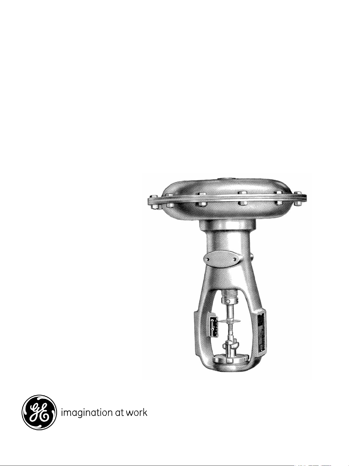
Model 37/38
Masoneilan* Spring-Diaphragm Actuators
Instruction Manual
GE Data Classification: Public
Page 2

GE Proprietary and Confidential
2 | GE Oil & Gas
© 2014 Genera l Electric Co mpany. All rights reserved.
Page 3

GE Proprietary and Confidential
© 2014 Genera l Electric Co mpany. All rights reserved.
Masoneilan 37-38 Serie s Actuators Instruction Manual | 3
THESE INSTRUCTIONS PROVIDE THE CUSTOMER/OPERATOR WITH IMPORTANT PROJECT-SPECIFIC REFERENCE
INFORMATION IN ADDITION TO THE CUSTOMER/OPERATOR’S NORMAL OPERATION AND MAINTENANCE
PROCEDURES. SINCE OPERATION AND MAINTENANCE PHILOSOPHIES VARY, GE (GENERAL ELECTRIC COMPANY
AND ITS SUBSIDIARIES AND AFFILIATES) DOES NOT ATTEMPT TO DICTATE SPECIFIC PROCEDURES, BUT TO
PROVIDE BASIC LIMITATIONS AND REQUIREMENTS CREATED BY THE TYPE OF EQUIPMENT PROVIDED.
THESE INSTRUCTIONS ASSUME THAT OPERATORS ALREADY HAVE A GENERAL UNDERSTANDING OF THE
REQUIREMENTS FOR SAFE OPERATION OF MECHANICAL AND ELECTRICAL EQUIPMENT IN POTENTIALLY
HAZARDOUS ENVIRONMENTS. THEREFORE, THESE INSTRUCTIONS SHOULD BE INTERPRETED AND APPLIED IN
CONJUNCTION WITH THE SAFETY RULES AND REGULATIONS APPLICABLE AT THE SITE AND THE PARTICULAR
REQUIREMENTS FOR OPERATION OF OTHER EQUIPMENT AT THE SITE.
THESE INSTRUCTIONS DO NOT PURPORT TO COVER ALL DETAILS OR VARIATIONS IN EQUIPMENT NOR TO
PROVIDE FOR EVERY POSSIBLE CONTINGENCY TO BE MET IN CONNECTION WITH INSTALLATION, OPERATION
OR MAINTENANCE. SHOULD FURTHER INFORMATION BE DESIRED OR SHOULD PARTICULAR PROBLEMS ARISE
WHICH ARE NOT COVERED SUFFICIENTLY FOR THE CUSTOMER/OPERATOR'S PURPOSES THE MATTER SHOULD BE
REFERRED TO GE.
THE RIGHTS, OBLIGATIONS AND LIABILITIES OF GE AND THE CUSTOMER/OPERATOR ARE STRICTLY LIMITED TO
THOSE EXPRESSLY PROVIDED IN THE CONTRACT RELATING TO THE SUPPLY OF THE EQUIPMENT. NO ADDITIONAL
REPRESENTATIONS OR WARRANTIES BY GE REGARDING THE EQUIPMENT OR ITS USE ARE GIVEN OR IMPLIED BY
THE ISSUE OF THESE INSTRUCTIONS.
THESE INSTRUCTIONS CONTAIN PROPRIETARY INFORMATION OF GE, AND ARE FURNISHED TO THE CUSTOMER/
OPERATOR SOLELY TO ASSIST IN THE INSTALLATION, TESTING, OPERATION, AND/OR MAINTENANCE OF THE
EQUIPMENT DESCRIBED. THIS DOCUMENT SHALL NOT BE REPRODUCED IN WHOLE OR IN PART NOR SHALL ITS
CONTENTS BE DISCLOSED TO ANY THIRD PARTY WITHOUT THE WRITTEN APPROVAL OF GE.
Page 4

GE Proprietary and Confidential
Description
Effective
Area (sq. in.)
11
71
1
13
105
1 ½
15
145
2
18
200
2 ½
18L
200
4
Life Period
The Masoneilan 37/38 spring-diaphragm
actuator is a simple, powerful, mechanical device.
There are two general types: Air-to-Extend Stem
and Air-to-Retract Stem. Actuators are designated
by case size: Nos. 9, 11, 13, 15, 18 and 18L.
The nominal range of a spring-diaphragm
actuator is the air pressure range in pounds per
square inch (psi) for rated stroke under no load.
Common ranges are 3–15 psi and 6–30 psi. The
spring range and maximum allowable supply
pressure are marked on the serial plate. For a 3–
15 psi nominal range, the stem will start to stroke
when the air pressure reaches 3 psi, and will
complete the stroke when the pressure reaches
15 psi (plus or minus 5%).
In the air-to-extend actuator, conformation of the
molded diaphragm to the diaphragm plate serves
as a flexible upper guide for the actuator stem
(26). The lower guide is an oil-impregnated bronze
bushing (37) located in the spring adjustor (36).
The air-to-retract actuator differs from the air-toextend unit in that the spring (22), spring barrel
(71) and spring adjustor (36) are located above the
diaphragm plate (40) and diaphragm (39) which
are inverted. A gasket (19) at the joint of the
diaphragm case and yoke and a packing box
aroun
d the actuator stem prevents air leakage.
The diaphragm acts as a flexible upper guide and
the packing box assembly as the lower guide for
the actuator stem.
Air connections are 1/4" NPT. Connections are
located in the upper diaphragm case (air-toextend actuators) or yoke (air-to-retract actuators).
Standard
Actuator Size
9 45 ¾
Diaphragm
Maximum
Stroke (in.)
The current estimated useful life period for the
Masoneilan 37/38 actuator is 25+ years. To
maximize the useful life of the product it is
essential to conduct annual inspections, routine
maintenance and ensure proper installation to
avoid any unintended stresses on the product. The
specific operating conditions and environmental
conditions will also impact the useful life of the
product. Consult the factory for guidance on
specific applications if required prior to installation.
Maintenance
Air-to-Extend Actuators (Type 37)
Diaphragm Replacement
Before disassembling the actuator, all spring
compression should be relieved by turning the spring
adjustor (36), to prevent the upper case popping up
when the cap screws (45) are removed. This is
especially important on actuators with a high initial
spring setting. Remove cap screws (45), nuts (46) and
upper diaphragm case (43). Remove nut (30) and
washer (41) to release the diaphragm (39). If possible,
the replacement diaphragm should be of the molded
type supplied by Masoneilan, but in an emergency a
diaphragm may be cut from flat sheet stock for up to
and including No. 15 actuators. To allow sufficient
stroke without restriction due to flatness of the
diaphragm, the diaphragm bolt circle should be
about 10% greater than that of the diaphragm case.
Replace washer (41), nut (30) and upper diaphragm
case.
Spring Adjustment
An air supply, with a gauge and regulator, should be
piped to the upper diaphragm case for this
adjustment. Adjust spring compression so that the
actuator sem (26) just begins to move when air
pressure reaches minimum pressure of the range
stamped on the serial plate. This movement is most
easily detected by feeling the stem as air pressure is
applied.
Note: Adjust spring compression only when there is
no air pressure on diaphragm.
4 | GE Oil & Gas
© 2014 Genera l Electric Co mpany. All rights reserved.
Page 5

GE Proprietary and Confidential
© 2014 Genera l Electric Co mpany. All rights reserved.
Masoneilan 37-38 Serie s Actuators Instruction Manual | 5
Air-to-Retract Actuators (Type 38)
Diaphragm Replacement
The procedure is the same as for air-to-extend
actuators except that the entire upper case
assembly (including spring barrel (71), spring (22),
spring seats (33 and 34), nut (30) and diaphragm
plate (40) must be removed to release the
diaphragm. Install a new diaphragm and
reassembly the above parts.
Spring Adjustment
The procedure is identical with that for air-toextend actuators except that supply air is piped to
the 1/4" port in the yoke.
Packing Box
The packing box is subject to low air pressure only
and requires minimum maintenance.
The packing rings have a square section and are
made of carbon core with braided PTFE jacket. The
packing may be added to or completely replaced
without disassembling either the actuator or the
mechanism (or valve) to which it is attached. Be
sure to tighten packing nut (20) lightly. Overtightening will cause excessive friction, resulting in
sluggish performance.
Page 6

GE Proprietary and Confidential
Ref.
No.
**
15
Gasket (packing box)
17
Yoke
18
Cap Screw (L case to yoke)
**
19
Gasket (L case to yoke)
20
Packing Nut
21
Snap Ring
22
Actuator Spring
Actuator Spring
22A
**
Actuator Stem
26
Nut (actuator stem)
30
Packing Box
31
Recommended spare parts
Part Name
Air-to-Extend
Actuators
(Type 37)
Case Nos. 9, 11 & 13 Case Nos. 15, 18 & 18L
Air-to-Extend
Actuators
(Type 38)
Case Nos. 9, 11 & 13 Case Nos. 15, 18 & 18L
Computer
Abbrev.
PACKING
USPR ST
LSPR ST
PIP PLG
SPR ADJ
BUSHING
DIAPHRM
DPH PLT
PDH WSH
U D CSE
L D CSE
Ref.
No.
45
46
56
57
70
71
72
73
74
Part Name
Cap Screw (diaph. case)
Nut (diaph. case)
Travel Indicator Scale
Machine Screw
Ball and Retainer
Spring Barrel
Spring Barrel Cap
Ball Bearing Race
Cap Screw (SBL to U D CSE)
Computer
Abbrev.
GASKET
YOKE
CAP SCR
GASKET
PKG NUT
SNP RNG
ACT SPR
ACT SPR
ACT STM
NUT
PKG BOX
Parts Reference
Ref.
No.
**
32
33
34
35
36
37
**
39
40
41
43
44
Part Name
Packing
Spring Seat (upper)
Spring Seat (lower)
Pipe Plug
Spring Adjustor
Bushing (spring adjuster)
Diaphragm
Diaphragm Plate
Diaphragm Washer
Upper Diaphragm Case
Lower Diaphragm Case
Computer
Abbrev.
CAP SCR
NUT
T I SCL MCN
SCR BALL &
RTN SPR
BRL
SBL CAP
BBG RCE
CAP SCR
6 | GE Oil & Gas
© 2014 Genera l Electric Co mpany. All rights reserved.
Page 7

GE Proprietary and Confidential
© 2014 Genera l Electric Co mpany. All rights reserved.
Masoneilan 37-38 Serie s Actuators Instruction Manual | 7
Notes
Page 8

DIRECT SALES OFFICE LOCATIONS
AUSTRALIA
Brisbane:
Phone: +61-7-3001-4319
Fax: +61-7-3001-4399
Perth:
Phone: +61-8-6595-7018
Fax: +61 8 6595-7299
Melbourne:
Phone: +61-3-8807-6002
Fax : +61-3-8807-6577
BELGIUM
Phone: +32-2-344-0970
Fax: +32-2-344-1123
BRAZIL
Phone: +55-11-2146-3600
Fax: +55-11-2146-3610
CHINA
Phone: +86-10-5689-3600
Fax: +86-10-5689-3800
FRANCE
Courbevoie
Phone: +33-1-4904-9000
Fax: +33-1-4904-9010
GERMANY
Ratingen
Phone: +49-2102-108-0
Fax: +49-2102-108-111
INDIA
Mumbai
Phone: +91-22-8354790
Fax: +91-22-8354791
New Delhi
Phone: +91-11-2-6164175
Fax: +91-11-5-1659635
ITALY
Phone: +39-081-7892-111
Fax: +39-081-7892-208
JAPAN
Chiba
Phone: +81-43-297-9222
Fax: +81-43-299-1115
KOREA
Phone: +82-2-2274-0748
Fax: +82-2-2274-0794
MALAYSIA
Phone: +60-3-2161-0322
Fax: +60-3-2163-6312
MEXICO
Phone: +52-55-3640-5060
THE NETHERLANDS
Phone: +0031-15-3808666
Fax: +0031-18-1641438
RUSSIA
Veliky Novgorod
Phone: +7-8162-55-7898
Fax: +7-8162-55-7921
Moscow
Phone: +7 495-585-1276
Fax: +7 495-585-1279
SAUDI ARABIA
Phone: +966-3-341-0278
Fax: +966-3-341-7624
SINGAPORE
Phone: +65-6861-6100
Fax: +65-6861-7172
SOUTH AFRICA
Phone: +27-11-452-1550
Fax: +27-11-452-6542
SOUTH & CENTRAL
AMERICA AND THE CARIBBEAN
Phone: +55-12-2134-1201
Fax: +55-12-2134-1238
SPAIN
Phone: +34-93-652-6430
Fax: +34-93-652-6444
UNITED ARAB EMIRATES
Phone: +971-4-8991-777
Fax: +971-4-8991-778
UNITED KINGDOM
Wooburn Green
Phone: +44-1628-536300
Fax: +44-1628-536319
UNITED STATES
Massachusetts
Phone: +1-508-586-4600
Fax: +1-508-427-8971
Corpus Christi, Texas
Phone: +1-361-881-8182
Fax: +1-361-881-8246
Deer Park, Texas
Phone: +1-281-884-1000
Fax: +1-281-884-1010
Houston, Texas
Phone: +1-281-671-1640
Fax: +1-281-671-1735
Visit us online at:
d
www.geoilan
gas.com/valves
*Masoneilan is a regis tered trademark of the General Electric Company.
Other company names and product names used in this document are the
registered trademarks or trademarks of their respective owners.
© 2014 General Electric Company. All rights reser ved.
GEA31171A 08/2014
 Loading...