

Page 1
GE
Digital Energy
Multilink ML3000
Ethernet Communications
Switch
Instruction Manual
Firmware Revision 5.0
Manual P/N: 1601-0049-A1
Publication Number: GEK-113632
Copyright © 2012 GE Digital Energy
GE Digital Energy
650 Markland Street
Markham, Ontario
Canada L6C 0M1
Tel: +1 905 927 7070 Fax: +1 905 927-5098
Internet: http://www.gedigitalenergy.com
*1601-0220-A1*
GE Multilin's Quality
Management System is
registered to ISO 9001:2008
QMI # 005094
UL # A3775
Page 2

Copyright © 2012 GE Multilin Inc. All rights reserved.
GE Digital Energy Multilink ML3000 Instruction Manual for revision 5.0.
Multilink ML3000 is a registered trademark of GE Digital Energy.
The contents of this manual are the property of GE Multilin Inc. This documentation is
furnished on license and may not be reproduced in whole or in part without the permission
of GE Multilin. The manual is for informational use only and is subject to change without
notice.
Part number: 1601-0049-A1 (October 2012)
Page 3

These instructions do not purport to cover all details or variations in equipment nor provide for every
possible contingency to be met in connection with installation, operation, or maintenance. Should further
information be desired or should particular problems arise which are not covered sufficiently for the
purchaser’s purpose, the matter should be referred to the General Electric Company.
To the extent required the products described herein meet applicable ANSI, IEEE, and NEMA standards; but
no such assurance is given with respect to local codes and ordinances because they vary greatly.
© 2012 GE Digital Energy Incorporated. All rights reserved.
GE Digital Energy A1 instruction manual for revision 5.0.
Multilink ML3000 is a registered trademark of GE Digital Energy Inc.
NEBS is a trademark of Telcordia Technologies
The contents of this manual are the property of GE Digital Energy Inc. This documentation is furnished on
license and may not be reproduced in whole or in part without the permission of GE Digital Energy. The
content of this manual is for informational use only and is subject to change without notice.
Part numbers contained in this manual are subject to change without notice, and should therefore be
verified by GE Digital Energy before ordering.
Part number: 1601-0123-A1 (February 2012)
Federal Communications Commission
Radio Frequency Interference Statement
This equipment generates, uses and can radiate frequency energy and if not installed and used properly
in strict accordance with the manufacturer's instructions, may cause interference to radio
communication. It has been tested and found to comply with the limits for a Class A computing device in
accordance with the specifications in Subpart J of Part 15 of FCC rules, which are designed to provide
reasonable protection against such interference when operated in a commercial environment. Operation
of this equipment in a residential area is likely to cause interference, in which case the user, at their own
expense, will be required to take whatever measures may be required to correct the interference.
Canadian Emissions Statement
This Class A digital apparatus meets all requirements of the Canadian Interference-Causing Equipment
Regulations.
Cet appareil respecte toutes les exigences du Réglement sur le matériel du Canada. Cet appareil est
Classe A..
Electrical Safety requirements:
• This product is to be installed Only in Restricted Access Areas (Dedicated Equipment Rooms, Electrical
Closets, or the like).
• 48 V DC products shall be installed with a readily accessible disconnect device in the building
installation supply circuit to the product.
• This product shall be provided with a maximum 10 A DC Listed fuse or circuit breaker in the supply
circuit when connected to a 48 V centralized DC source.
• The external power supply for DC units shall be a Listed, Direct Plug In power unit, marked Class 2, or
Listed ITE Power Supply, marked LP, which has suitably rated output voltage (i.e. 48 V DC) and suitable
rated output current.
• Product does not contain user replaceable fuses. Any internal fuses can ONLY be replaced by GE
Digital Energy.
• Models with a DC power source must be supplied with a DC supply source to the equipment that is
derived from a secondary circuit which is isolated from the AC Mains by Double or Reinforced
Insulation (eg: UL Certified ITE power supply which provides Double or Reinforced Insulation).
Page 4

GENERAL SAFETY PRECAUTIONS
Note
• Failure to observe and follow the instructions provided in the equipment manual(s)
could cause irreversible damage to the equipment and could lead to property
damage, personal injury and/or death.
• Before attempting to use the equipment, it is important that all danger and
caution indicators are reviewed.
• If the equipment is used in a manner not specified by the manufacturer or
functions abnormally, proceed with caution. Otherwise, the protection provided by
the equipment may be impaired and can result in Impaired operation and injury.
• Caution: Hazardous voltages can cause shock, burns or death.
• Installation/service personnel must be familiar with general device test practices,
electrical awareness and safety precautions must be followed.
• Before performing visual inspections, tests, or periodic maintenance on this device
or associated circuits, isolate or disconnect all hazardous live circuits and sources
of electric power.
• Failure to shut equipment off prior to removing the power connections could
expose you to dangerous voltages causing injury or death.
• All recommended equipment that should be grounded and must have a reliable
and un-compromised grounding path for safety purposes, protection against
electromagnetic interference and proper device operation.
• Equipment grounds should be bonded together and connected to the facility’s
main ground system for primary power.
• Keep all ground leads as short as possible.
• At all times, equipment ground terminal must be grounded during device
operation and service.
• In addition to the safety precautions mentioned all electrical connections made
must respect the applicable local jurisdiction electrical code.
• This product contains Class I lasers.
Page 5

BATTERY DISPOSAL
EN Battery Disposal
This product contains a battery that cannot be disposed of as
unsorted municipal waste in the European Union. See the product
documentation for specific battery information. The battery is marked
with this symbol, which may include lettering to indicate cadmium
(Cd), lead (Pb), or mercury (Hg). For proper recycling return the battery
to your supplier or to a designated collection point. For more
information see: www.recyclethis.info.
CS Nakládání s bateriemi
Tento produkt obsahuje baterie, které nemohou být zneškodněny v
Evropské unii jako netříděný komunální odpadu. Viz dokumentace k
produktu pro informace pro konkrétní baterie. Baterie je označena
tímto symbolem, který může zahrnovat i uvedena písmena, kadmium
(Cd), olovo (Pb), nebo rtuť (Hg). Pro správnou recyklaci baterií vraťte
svémudodavateli nebo na určeném sběrném místě. Pro více informací
viz: www.recyclethis.info
DA Batteri affald
Dette produkt indeholder et batteri som ikke kan bortskaffes sammen
med almindeligt husholdningsaffald i Europa. Se produktinformation
for specifikke informationer om batteriet . Batteriet er forsynet med
indgraveret symboler for hvad batteriet indeholder: kadmium (Cd), bly
(Pb) og kviksølv (Hg). Europæiske brugere af elektrisk udstyr skal
aflevere kasserede produkter til genbrug eller til leverandøren.
Yderligere oplysninger findes på webstedet www.recyclethis.info.
DE Entsorgung von Batterien
Dieses Produkt beinhaltet eine Batterie, die nicht als unsortierter
städtischer Abfall in der europäischen Union entsorgt werden darf.
Beachten Sie die spezifischen Batterie-informationen in der
Produktdokumentation. Die Batterie ist mit diesem Symbol
gekennzeichnet, welches auch Hinweise auf möglicherweise
enthaltene Stoffe wie Kadmium (Cd), Blei (Pb) oder Quecksilber
(Hektogramm) darstellt. Für die korrekte Wiederverwertung bringen
Sie diese Batterie zu Ihrem lokalen Lieferanten zurück oder entsorgen
Sie das Produkt an den gekennzeichneten Sammelstellen. Weitere
Informationen hierzu finden Sie auf der folgenden Website:
www.recyclethis.info.
EL Απόρριψη μπαταριών
Αυτό το προϊόν περιέχει μια μπαταρία που δεν πρέπει να
απορρίπτεται σε δημόσια συστήματα απόρριψης στην Ευρωπαϊκή
Κοινότητα.
∆είτε την τεκμηρίωση του προϊόντος για συγκεκριμένες
πληροφορίες που αφορούν τη μπαταρία. Η μπαταρία είναι φέρει
σήμανση με αυτό το σύμβολο, το οποίο μπορεί να περιλαμβάνει
γράμματα για να δηλώσουν το κάδμιο (Cd), τον μόλυβδο (Pb), ή τον
υδράργυρο (Hg). Για την κατάλληλη ανακύκλωση επιστρέψτε την
μπαταρία στον προμηθευτή σας ή σε καθορισμένο σημείο
συλλογής.
Για περισσότερες πληροφορίες δείτε: www.recyclethis.info.
ES Eliminacion de baterias
Este producto contiene una batería que no se pueda eliminar como
basura normal sin clasificar en la Unión Europea. Examine la
documentación del producto para la información específica de la
batería. La batería se marca con este símbolo, que puede incluir siglas
para indicar el cadmio (Cd), el plomo (Pb), o el mercurio (Hg ). Para el
reciclaje apropiado, devuelva este producto a su distribuidor ó
deshágase de él en los puntos de reciclaje designados. Para mas
información: wwwrecyclethis.info.
ET Patareide kõrvaldamine
Käesolev toode sisaldab patareisid, mida Euroopa Liidus ei tohi
kõrvaldada sorteerimata olmejäätmetena. Andmeid patareide kohta
vaadake toote dokumentatsioonist. Patareid on märgistatud
käesoleva sümboliga, millel võib olla kaadmiumi (Cd), pliid (Pb) või
elavhõbedat (Hg) tähistavad tähed. Nõuetekohaseks ringlusse
võtmiseks tagastage patarei tarnijale või kindlaksmääratud
vastuvõtupunkti. Lisainformatsiooni saab Internetist aadressil:
www.recyclethis.info.
FI Paristoje ja akkujen hävittäminen
Tuote sisältää pariston, jota ei saa hävittää Euroopan Unionin alueella
talousjätteen mukana. Tarkista tuoteselosteesta tuotteen tiedot.
Paristo on merkitty tällä symbolilla ja saattaa sisältää cadmiumia (Cd),
lyijyä (Pb) tai elohopeaa (Hg). Oikean kierrätystavan varmistamiseksi
palauta tuote paikalliselle jälleenmyyjälle tai palauta se paristojen
keräyspisteeseen. Lisätietoja sivuilla www.recyclethis.info.
FR Élimination des piles
Ce produit contient une batterie qui ne peuvent être éliminés comme
déchets municipaux non triés dans l'Union européenne. Voir la
documentation du produit au niveau des renseignements sur la pile.
La batterie est marqué de ce symbole, qui comprennent les
indications cadmium (Cd), plomb (Pb), ou mercure (Hg). Pour le
recyclage, retourner la batterie à votre fournisseur ou à un point de
collecte. Pour plus d'informations, voir: www.recyclethis.info.
HU Akkumulátor hulladék kezelése
Ezen termék akkumulátort tartalmaz, amely az Európai Unión belül
csak a kijelölt módon és helyen dobható ki. A terméken illetve a
mellékelt ismertetőn olvasható a kadmium (Cd), ólom (Pb) vagy higany
(Hg) tartalomra utaló betűjelzés. A hulladék akkumulátor leadható a
termék forgalmazójánál új akkumulátor vásárlásakor, vagy a kijelölt
elektronikai hulladékudvarokban. További információ a
www.recyclethis.info oldalon.
IT Smaltimento batterie
Questo prodotto contiene una batteria che non può essere smaltita
nei comuni contenitori per lo smaltimento rifiuti, nell' Unione Europea.
Controllate la documentazione del prodotto per le informazioni
specifiche sulla batteria. La batteria è contrassegnata con questo
simbolo e può includere alcuni caratteri ad indicare la presenza di
cadmio (Cd), piombo (Pb) oppure mercurio (Hg). Per il corretto
smaltimento, potete restituirli al vostro fornitore locale, oppure
rivolgervi e consegnarli presso i centri di raccolta preposti. Per
maggiori informazioni vedere: ww.recyclethis.info.
Page 6

LT Baterijų šalinimas
Šios įrangos sudėtyje yra baterijų, kurias draudžiama šalinti Europos
Sąjungos viešose nerūšiuotų atliekų šalinimo sistemose. Informaciją
apie baterijas galite rasti įrangos techninėje dokumentacijoje.
Baterijos žymimos šiuo simboliu, papildomai gali būti nurodoma kad
baterijų sudėtyje yra kadmio (Cd), švino (Pb) ar gyvsidabrio (Hg).
Eksploatavimui nebetinkamas baterijas pristatykite į tam skirtas
surinkimo vietas arba grąžinkite jas tiesioginiam tiekėjui, kad jos būtų
tinkamai utilizuotos. Daugiau informacijos rasite šioje interneto
svetainėje: www.recyclethis.info.
LV Bateriju likvidēšana
Šis produkts satur bateriju vai akumulatoru, kuru nedrīkst izmest
Eiropas Savienībā esošajās sadzīves atkritumu sistēmās. Sk. produkta
dokumentācijā, kur ir norādīta konkrēta informācija par bateriju vai
akumulatoru. Baterijas vai akumulatora marķējumā ir šis simbols, kas
var ietvert burtus, kuri norāda kadmiju (Cd), svinu (Pb) vai dzīvsudrabu
(Hg). Pēc ekspluatācijas laika beigām baterijas vai akumulatori
jānodod piegādātājam vai specializētā bateriju savākšanas vietā.
Sīkāku informāciju var iegūt vietnē: www.recyclethis.info.
NL Verwijderen van baterijen
Dit product bevat een batterij welke niet kan verwijdert worden via de
gemeentelijke huisvuilscheiding in de Europese Gemeenschap.
Gelieve de product documentatie te controleren voor specifieke
batterij informatie. De batterijen met deze label kunnen volgende
indictaies bevatten cadium (Cd), lood (Pb) of kwik (Hg). Voor correcte
vorm van kringloop, geef je de producten terug aan jou locale
leverancier of geef het af aan een gespecialiseerde verzamelpunt.
Meer informatie vindt u op de volgende website: www.recyclethis.info.
NO Retur av batteri
Dette produkt inneholder et batteri som ikke kan kastes med usortert
kommunalt søppel i den Europeiske Unionen. Se
produktdokumentasjonen for spesifikk batteriinformasjon. Batteriet er
merket med dette symbolet som kan inkludere symboler for å indikere
at kadmium (Cd), bly (Pb), eller kvikksølv (Hg) forekommer. Returner
batteriet til leverandøren din eller til et dedikert oppsamlingspunkt for
korrekt gjenvinning. For mer informasjon se: www.recyclethis.info.
PL Pozbywanie się zużytych baterii
Ten produkt zawiera baterie, które w Unii Europejskiej mogą być
usuwane tylko jako posegregowane odpady komunalne. Dokładne
informacje dotyczące użytych baterii znajdują się w dokumentacji
produktu. Baterie oznaczone tym symbolem mogą zawierać
dodatkowe oznaczenia literowe wskazujące na zawartość kadmu
(Cd), ołowiu (Pb) lub rtęci (Hg). Dla zapewnienia właściwej utylizacji,
należy zwrócić baterie do dostawcy albo do wyznaczonego punktu
zbiórki. Więcej informacji można znaleźć na stronie internetowej
www.recyclethis.info.
PT Eliminação de Baterias
Este produto contêm uma bateria que não pode ser considerado lixo
municipal na União Europeia. Consulte a documentação do produto
para obter informação específica da bateria. A bateria é identificada
por meio de este símbolo, que pode incluir a rotulação para indicar o
cádmio (Cd), chumbo (Pb), ou o mercúrio (hg). Para uma reciclagem
apropriada envie a bateria para o seu fornecedor ou para um ponto
de recolha designado. Para mais informação veja:
www.recyclethis.info.
RU Утилизация батарей
Согласно европейской директиве об отходах электрического и
электронного оборудования, продукты, содержащие батареи,
нельзя утилизировать как обычные отходы на территории ЕС.
Более подробную информацию вы найдете в документации к
продукту. На этом символе могут присутствовать буквы, которые
означают, что батарея собержит кадмий (Cd), свинец (Pb) или ртуть
(Hg). Для надлежащей
утилизации по окончании срока
эксплуатации пользователь должен возвратить батареи
локальному поставщику или сдать в специальный пункт приема.
Подробности можно найти на веб-сайте: www.recyclethis.info.
SK Zaobchádzanie s batériami
Tento produkt obsahuje batériu, s ktorou sa v Európskej únii nesmie
nakladať ako s netriedeným komunálnym odpadom. Dokumentácia k
produktu obsahuje špecifické informácie o batérii. Batéria je
označená týmto symbolom, ktorý môže obsahovať písmená na
označenie kadmia (Cd), olova (Pb), alebo ortuti (Hg). Na správnu
recykláciu vráťte batériu vášmu lokálnemu dodávateľovi alebo na
určené zberné miesto. Pre viac informácii pozrite:
www.recyclethis.info.
SL Odlaganje baterij
Ta izdelek vsebuje baterijo, ki je v Evropski uniji ni dovoljeno
odstranjevati kot nesortiran komunalni odpadek. Za posebne
informacije o bateriji glejte dokumentacijo izdelka. Baterija je
označena s tem simbolom, ki lahko vključuje napise, ki označujejo
kadmij (Cd), svinec (Pb) ali živo srebro (Hg). Za ustrezno recikliranje
baterijo vrnite dobavitelju ali jo odstranite na določenem zbirališču. Za
več informacij obiščite spletno stran: www.recyclethis.info.
SV Kassering av batteri
Denna produkt innehåller ett batteri som inte får kastas i allmänna
sophanteringssytem inom den europeiska unionen. Se
produktdokumentationen för specifik batteriinformation. Batteriet är
märkt med denna symbol, vilket kan innebära att det innehåller
kadmium (Cd), bly (Pb) eller kvicksilver (Hg). För korrekt återvinning
skall batteriet returneras till leverantören eller till en därför avsedd
deponering. För mer information, se: www.recyclethis.info. TR Pil Geri
Dönüşümü Bu ürün Avrupa Birliği genel atık sistemlerine atılmaması
gereken pil içermektedir. Daha detaylı pil bilgisi için ürünün
kataloğunu inceleyiniz. Bu sembolle işaretlenmiş piller Kadmiyum(Cd),
Kurşun(Pb) ya da Civa(Hg) içerebilir. Doğru geri dönüşüm için ürünü
yerel tedarikçinize geri veriniz ya da özel işaretlenmiş toplama
noktlarına atınız. Daha fazla bilgi için: www.recyclethis.info.
TR Pil Geri Dönüşümü
Bu ürün Avrupa Birliği genel atık sistemlerine atılmaması gereken pil
içermektedir. Daha detaylı pil bilgisi için ürünün kataloğunu inceleyiniz.
Bu sembolle işaretlenmiş piller Kadmiyum(Cd), Kurşun(Pb) ya da
Civa(Hg) içerebilir. Doğru geri dönüşüm için ürünü yerel tedarikçinize
geri veriniz ya da özel işaretlenmiş toplama noktlarına atınız. Daha
fazla bilgi için: www.recyclethis.info.
Global Contacts
North America 1 905-927-7070
Latin America +55 11 3614 1700
Europe, Middle East, Africa +(34) 94 485 88 00
Asia +86-21-2401-3208
India +91 80 41314617
Page 7

CHAPTER 0:
Safety words and definitions
The following symbols used in this document indicate the following conditions.
Note
Indicates a hazardous situation which, if not avoided, will result in death or serious
injury.
Note
Indicates a hazardous situation which, if not avoided, could result in death or serious
injury.
Note
Indicates a hazardous situation which, if not avoided, could result in minor or
moderate injury.
Note
Indicates practices not related to personal injury.
MULTILINK ML3000 ETHERNET COMMUNICATIONS SWITCH – INSTRUCTION MANUAL 0–7
Page 8

CHAPTER 0:
0–8 MULTILINK ML3000 ETHERNET COMMUNICATIONS SWITCH – INSTRUCTION MANUAL
Page 9

TOC TABLE OF CONTENTS
TABLE OF CONTENTS
1: INTRODUCTION GETTING STARTED ...............................................................................................................................1-1
I
NSPECTING THE PACKAGE AND PRODUCT ..........................................................................1-1
ORDERING ...............................................................................................................................................1-2
O
RDER CODES .........................................................................................................................1-2
SPECIFICATIONS ...................................................................................................................................1-4
T
ECHNICAL SPECIFICATIONS ..................................................................................................1-4
E
NVIRONMENTAL SPECIFICATIONS ........................................................................................1-6
P
HYSICAL SPECIFICATIONS .....................................................................................................1-6
C
OMPLIANCE ............................................................................................................................1-7
A
PPROVALS ...............................................................................................................................1-8
FIRMWARE OVERVIEW ......................................................................................................................1-9
C
OMMAND LINE FIRMWARE ..................................................................................................1-9
E
NERVISTA SOFTWARE ...........................................................................................................1-9
B
EFORE STARTING ...................................................................................................................1-10
COMMAND LINE INTERFACE FIRMWARE ...................................................................................1-11
C
ONSOLE CONNECTION .........................................................................................................1-11
C
ONSOLE SETUP ......................................................................................................................1-11
C
ONSOLE SCREEN ...................................................................................................................1-11
L
OGGING IN FOR THE FIRST TIME .........................................................................................1-12
A
UTOMATIC IP ADDRESS CONFIGURATION .........................................................................1-12
S
ETTING THE IP PARAMETERS ...............................................................................................1-13
P
RIVILEGE LEVELS ....................................................................................................................1-15
U
SER MANAGEMENT ...............................................................................................................1-15
H
ELP ..........................................................................................................................................1-16
E
XITING .....................................................................................................................................1-18
ENERVISTA SECURE WEB MANAGEMENT .................................................................................1-19
L
OGGING IN FOR THE FIRST TIME .........................................................................................1-19
P
RIVILEGE LEVELS ....................................................................................................................1-20
U
SER MANAGEMENT ...............................................................................................................1-20
M
ODIFYING THE PRIVILEGE LEVEL ........................................................................................1-24
H
ELP ..........................................................................................................................................1-25
E
XITING .....................................................................................................................................1-26
ML3000 FIRMWARE UPDATES .......................................................................................................1-27
U
PDATING MULTILINK FIRMWARE ........................................................................................1-27
S
ELECTING THE PROPER VERSION ........................................................................................1-27
U
PDATING THROUGH THE COMMAND LINE .........................................................................1-27
U
PDATING THROUGH THE ENERVISTA SOFTWARE ..............................................................1-28
2: PRODUCT DESCRIPTION OVERVIEW ...............................................................................................................................................2-1
I
NTRODUCTION TO THE ML3000 .........................................................................................2-1
D
ESIGN ASPECTS .....................................................................................................................2-2
ML3000 MODULES ............................................................................................................................2-3
ML3000 M
M
ODULE A (100MB) - FOUR RJ45 PORTS (USE IN SLOTS 3-10) .................................2-4
M
ODULE G (100 MB) - FOUR MULTIMODE LC (USE IN SLOTS 3-10) ..........................2-4
M
ODULE K, MODULE M (100 MB) - FOUR SINGLEMODE LC (USE IN SLOTS 3-10) .. 2-5
M
ODULE H (100 MB) - FOUR MULTIMODE MTRJ (USE IN SLOTS 3-10) ....................2-5
MULTILINK ML3000 ETHERNET COMMUNICATIONS SWITCH – INSTRUCTION MANUAL TOC–1
ODULE LED DESIGNATIONS ............................................................................2-3
Page 10

TABLE OF CONTENTS
MODULE F, MODULE E (100 MB) - (USE IN SLOTS 3-10)
T
WO SC MULTIMODE OR TWO ST MULTIMODE ...........................2-6
M
ODULE J, MODULE L (100 MB) - (USE IN SLOTS 3-10)
T
WO SC SINGLEMODE .......................................................................2-6
M
ODULE N, (100 MB) - FOUR OPEN 100 MB SFP SLOTS (USE IN SLOTS 3-10) ......2-6
M
ODULE A (GB) - TWO GIGABIT RJ45 (USE IN SLOTS 1 AND 2 ONLY) ........................2-7
M
ODULE H (GB) - TWO GIGABIT SFPS (USE IN SLOTS 1 AND 2 ONLY) ........................2-7
FEATURES AND BENEFITS ................................................................................................................2-8
P
ACKET PRIORITIZATION, 802.1P QOS ...............................................................................2-8
F
RAME BUFFERING AND FLOW CONTROL ...........................................................................2-8
M
ULTILINK SWITCH SOFTWARE ............................................................................................2-8
R
EDUNDANT POWER SUPPLY ................................................................................................2-9
A
DDITIONAL FEATURES AND BENEFITS ................................................................................2-9
APPLICATIONS .......................................................................................................................................2-11
D
ESCRIPTION ............................................................................................................................2-11
ML3000 S
ML3000
ML3000
WITCH FOR VLAN APPLICATIONS .....................................................................2-11
FOR AN INDUSTRIAL APPLICATION .......................................................................2-11
IN A REDUNDANT RING TOPOLOGY .....................................................................2-12
3: INSTALLATION PREPARATION ........................................................................................................................................3-1
RECAUTIONS ...........................................................................................................................3-1
P
L
OCATING THE ML3000 .......................................................................................................3-1
CONNECTING ETHERNET MEDIA ...................................................................................................3-3
D
ESCRIPTION ............................................................................................................................3-3
C
ONNECTING ST-TYPE FIBER OPTICS (TWIST-LOCK) ..........................................................3-3
C
ONNECTING SC-TYPE FIBER OPTICS (SNAP-IN) ................................................................3-4
C
ONNECTING SINGLE-MODE FIBER OPTICS ........................................................................3-4
C
ONNECTING RJ45 TWISTED PAIR ......................................................................................3-4
C
ONNECTING GIGABIT MEDIA USING GBICS ......................................................................3-5
MECHANICAL INSTALLATION ..........................................................................................................3-6
R
ACK MOUNTING ....................................................................................................................3-6
R
ACK-MOUNTING, REVERSE MOUNT OPTION ......................................................................3-6
ELECTRICAL INSTALLATION .............................................................................................................3-7
P
OWERING THE ML3000 ......................................................................................................3-7
UL/CE R
A
D
EQUIREMENTS FOR DC-POWERED UNITS ...........................................................3-8
LARM CONTACTS ...................................................................................................................3-8
IELECTRIC STRENGTH (HI-POT) TESTING ............................................................................3-9
4: OPERATION FUNCTIONALITY ....................................................................................................................................4-1
WITCHING FUNCTIONALITY ..................................................................................................4-1
S
F
ILTERING AND FORWARDING ...............................................................................................4-1
A
DDRESS LEARNING ................................................................................................................4-1
S
TATUS LEDS ..........................................................................................................................4-2
U
P-LINK MANUAL SWITCHES (FOR RJ45 PORT ONLY) ......................................................4-2
A
UTO-CROSS(MDIX) AND AUTO-NEGOTIATION, FOR RJ-45 PORTS ..............................4-2
F
LOW CONTROL (IEEE 802.3X) ...........................................................................................4-3
P
OWER BUDGET CALCULATIONS WITH FIBER MEDIA ........................................................4-4
TROUBLESHOOTING ...........................................................................................................................4-6
O
VERVIEW ................................................................................................................................4-6
B
EFORE CALLING FOR ASSISTANCE ......................................................................................4-6
W
HEN CALLING FOR ASSISTANCE ........................................................................................4-6
TOC–2 MULTILINK ML3000 ETHERNET COMMUNICATIONS SWITCH – INSTRUCTION MANUAL
Page 11

TOC TABLE OF CONTENTS
5: IP ADDRESSING IP ADDRESS AND SYSTEM INFORMATION .................................................................................5-1
O
VERVIEW ................................................................................................................................5-1
IMPORTANCE OF AN IP ADDRESS .................................................................................................5-3
DHCP
AND BOOTP .................................................................................................................5-3
BOOTP DATABASE ....................................................................................................................5-3
C
ONFIGURING DHCP/BOOTP/MANUAL/AUTO ................................................................5-3
U
SING TELNET .........................................................................................................................5-5
SETTING PARAMETERS ......................................................................................................................5-8
S
ETTING SERIAL PORT PARAMETERS ....................................................................................5-8
S
YSTEM PARAMETERS .............................................................................................................5-8
D
ATE AND TIME .......................................................................................................................5-10
N
ETWORK TIME .......................................................................................................................5-10
SYSTEM CONFIGURATION ................................................................................................................ 5-14
S
AVING AND LOADING – COMMAND LINE ..........................................................................5-14
C
ONFIG FILE .............................................................................................................................5-14
D
ISPLAYING CONFIGURATION ................................................................................................5-17
S
AVING CONFIGURATION .......................................................................................................5-20
S
CRIPT FILE ..............................................................................................................................5-22
S
AVING AND LOADING – ENERVISTA SOFTWARE ...............................................................5-23
H
OST NAMES ...........................................................................................................................5-25
E
RASING CONFIGURATION .....................................................................................................5-27
IPV6 ............................................................................................................................................................5-31
I
NTRODUCTION TO IPV6 .........................................................................................................5-31
W
HAT’S CHANGED IN IPV6? .................................................................................................5-31
IP
V6 ADDRESSING ..................................................................................................................5-32
C
ONFIGURING IPV6 ................................................................................................................5-32
L
IST OF COMMANDS IN THIS CHAPTER .................................................................................5-34
6: ACCESS
CONSIDERATIONS
SECURING ACCESS ..............................................................................................................................6-1
D
ESCRIPTION ............................................................................................................................6-1
P
ASSWORDS .............................................................................................................................6-1
P
ORT SECURITY FEATURE .......................................................................................................6-2
CONFIGURING PORT SECURITY THROUGH THE COMMAND LINE INTERFACE .........6-3
C
OMMANDS ..............................................................................................................................6-3
A
LLOWING MAC ADDRESSES ...............................................................................................6-4
S
ECURITY LOGS .......................................................................................................................6-8
A
UTHORIZED MANAGERS .......................................................................................................6-10
CONFIGURING PORT SECURITY WITH ENERVISTA SOFTWARE .......................................6-12
C
OMMANDS ..............................................................................................................................6-12
L
OGS .........................................................................................................................................6-14
A
UTHORIZED MANAGERS .......................................................................................................6-16
7: ACCESS USING RADIUS INTRODUCTION TO 802.1X ..............................................................................................................7-1
D
ESCRIPTION ............................................................................................................................7-1
802.1
X PROTOCOL .................................................................................................................7-1
CONFIGURING 802.1X THROUGH THE COMMAND LINE INTERFACE ...........................7-4
C
OMMANDS ..............................................................................................................................7-4
E
XAMPLE ...................................................................................................................................7-6
CONFIGURING 802.1X WITH ENERVISTA SECURE WEB MANAGEMENT SOFTWARE 7-9
C
OMMANDS ..............................................................................................................................7-9
MULTILINK ML3000 ETHERNET COMMUNICATIONS SWITCH – INSTRUCTION MANUAL TOC–3
Page 12

TABLE OF CONTENTS
8: ACCESS USING
TACACS+
9: PORT MIRRORING &
SETUP
INTRODUCTION TO TACACS+ .........................................................................................................8-1
O
VERVIEW ................................................................................................................................8-1
TACACS+ F
TACACS+ P
LOW ....................................................................................................................8-2
ACKET .................................................................................................................8-2
CONFIGURING TACACS+ THROUGH THE COMMAND LINE INTERFACE ......................8-4
C
OMMANDS ..............................................................................................................................8-4
E
XAMPLE ...................................................................................................................................8-4
CONFIGURING TACACS+ WITH ENERVISTA SECURE WEB MANAGEMENT SOFTWARE 8-6
PORT MIRRORING ................................................................................................................................9-1
D
ESCRIPTION ............................................................................................................................9-1
PORT MIRRORING USING THE COMMAND LINE INTERFACE ............................................9-2
C
OMMANDS ..............................................................................................................................9-2
PORT SETUP ............................................................................................................................................9-3
C
OMMANDS ..............................................................................................................................9-3
F
LOW CONTROL ......................................................................................................................9-5
B
ACK PRESSURE ......................................................................................................................9-5
B
ROADCAST STORMS ..............................................................................................................9-8
L
INK LOSS ALERT ....................................................................................................................9-10
PORT MIRRORING USING ENERVISTA SECURE WEB MANAGEMENT SOFTWARE ...9-12
C
OMMANDS ..............................................................................................................................9-12
P
ORT SETUP .............................................................................................................................9-13
B
ROADCAST STORMS ..............................................................................................................9-16
10: VLAN VLAN DESCRIPTION ............................................................................................................................10-1
VERVIEW ................................................................................................................................10-1
O
T
AG VLAN VS. PORT VLAN ..................................................................................................10-3
CONFIGURING PORT VLANS THROUGH THE COMMAND LINE INTERFACE ...............10-4
D
ESCRIPTION ............................................................................................................................10-4
C
OMMANDS ..............................................................................................................................10-4
CONFIGURING PORT VLANS WITH ENERVISTA SECURE WEB MANAGEMENT SOFTWARE
10-6
D
ESCRIPTION ............................................................................................................................10-6
CONFIGURING TAG VLANS THROUGH THE COMMAND LINE INTERFACE ..................10-10
D
ESCRIPTION ............................................................................................................................10-10
C
OMMANDS ..............................................................................................................................10-10
E
XAMPLE ...................................................................................................................................10-11
CONFIGURING TAG VLANS WITH ENERVISTA SECURE WEB MANAGEMENT SOFTWARE
10-17
D
ESCRIPTION ............................................................................................................................10-17
11: VLAN REGISTRATION
OVER GARP
OVERVIEW ...............................................................................................................................................11-1
ESCRIPTION ............................................................................................................................11-1
D
GVRP C
GVRP O
ONCEPTS ....................................................................................................................11-1
PERATIONS ................................................................................................................11-2
CONFIGURING GVRP THROUGH THE COMMAND LINE INTERFACE ..............................11-6
C
OMMANDS ..............................................................................................................................11-6
GVRP O
PERATION NOTES .....................................................................................................11-6
CONFIGURING GVRP WITH ENERVISTA SECURE WEB MANAGEMENT SOFTWARE 11-8
E
XAMPLE ...................................................................................................................................11-8
TOC–4 MULTILINK ML3000 ETHERNET COMMUNICATIONS SWITCH – INSTRUCTION MANUAL
Page 13

TOC TABLE OF CONTENTS
12: SPANNING TREE
PROTOCOL (STP)
OVERVIEW ...............................................................................................................................................12-1
D
ESCRIPTION ............................................................................................................................12-1
F
EATURES AND OPERATION ...................................................................................................12-1
CONFIGURING STP ..............................................................................................................................12-3
13: RAPID SPANNING
TREE PROTOCOL
OVERVIEW ...............................................................................................................................................13-1
D
ESCRIPTION ............................................................................................................................13-1
RSTP C
ONCEPTS .....................................................................................................................13-1
T
RANSITION FROM STP TO RSTP .........................................................................................13-2
CONFIGURING RSTP THROUGH THE COMMAND LINE INTERFACE ...............................13-4
N
ORMAL RSTP ........................................................................................................................13-4
S
MART RSTP (RING-ONLY MODE) THROUGH THE COMMAND LINE INTERFACE ...........13-14
CONFIGURING STP/RSTP WITH ENERVISTA SECURE WEB MANAGEMENT SOFTWARE
13-16
N
ORMAL RSTP ........................................................................................................................13-16
S
MART RSTP (RING-ONLY MODE) WITH ENERVISTA SECURE WEB MANAGEMENT SOFTWARE
13-20
14: QUALITY OF SERVICE QOS OVERVIEW ....................................................................................................................................14-1
D
ESCRIPTION ............................................................................................................................14-1
Q
OS CONCEPTS .......................................................................................................................14-1
D
IFFSERV AND QOS ...............................................................................................................14-2
IP P
RECEDENCE .......................................................................................................................14-2
CONFIGURING QOS THROUGH THE COMMAND LINE INTERFACE ................................14-4
C
OMMANDS ..............................................................................................................................14-4
E
XAMPLE ...................................................................................................................................14-6
CONFIGURING QOS WITH ENERVISTA SECURE WEB MANAGEMENT SOFTWARE ..14-8
D
ESCRIPTION ............................................................................................................................14-8
15: IGMP OVERVIEW ...............................................................................................................................................15-1
ESCRIPTION ............................................................................................................................15-1
D
IGMP C
ONCEPTS ....................................................................................................................15-1
IP M
ULTICAST FILTERS ...........................................................................................................15-4
R
ESERVED ADDRESSES EXCLUDED FROM IP MULTICAST (IGMP) FILTERING .................15-4
IGMP S
UPPORT .......................................................................................................................15-5
CONFIGURING IGMP THROUGH THE COMMAND LINE INTERFACE ...............................15-6
C
OMMANDS ..............................................................................................................................15-6
E
XAMPLE ...................................................................................................................................15-8
CONFIGURING IGMP WITH ENERVISTA SECURE WEB MANAGEMENT SOFTWARE 15-11
E
XAMPLE ...................................................................................................................................15-11
16: SNMP OVERVIEW ...............................................................................................................................................16-1
ESCRIPTION ............................................................................................................................16-1
D
SNMP C
S
ONCEPTS ...................................................................................................................16-1
TANDARDS ..............................................................................................................................16-3
CONFIGURING SNMP THROUGH THE COMMAND LINE INTERFACE .............................16-4
C
OMMANDS ..............................................................................................................................16-4
E
XAMPLE ...................................................................................................................................16-5
CONFIGURING SNMP WITH ENERVISTA SECURE WEB MANAGEMENT SOFTWARE 16-10
E
XAMPLE ...................................................................................................................................16-10
MULTILINK ML3000 ETHERNET COMMUNICATIONS SWITCH – INSTRUCTION MANUAL TOC–5
Page 14

TABLE OF CONTENTS
CONFIGURING RMON ........................................................................................................................16-15
D
ESCRIPTION ............................................................................................................................16-15
C
OMMANDS ..............................................................................................................................16-15
17: LACP INCREASE NETWORK THROUGHPUT AND RELIABILITY ......................................................17-1
ONCEPTS ....................................................................................................................17-1
LACP C
LACP CONFIGURATION .....................................................................................................................17-3
18: MISCELLANEOUS
COMMANDS
ALARM RELAYS ......................................................................................................................................18-1
D
ESCRIPTION ............................................................................................................................18-1
C
ONFIGURING ALARM RELAYS THROUGH THE COMMAND LINE INTERFACE ..................18-2
C
ONFIGURING ALARM RELAYS WITH ENERVISTA SECURE WEB MANAGEMENT SOFTWARE
18-5
E-MAIL .......................................................................................................................................................18-6
D
ESCRIPTION ............................................................................................................................18-6
C
OMMANDS ..............................................................................................................................18-6
E
XAMPLE ...................................................................................................................................18-7
STATISTICS ..............................................................................................................................................18-9
V
IEWING PORT STATISTICS WITH ENERVISTA SECURE WEB MANAGEMENT SOFTWARE 18-9
SERIAL CONNECTIVITY .......................................................................................................................18-11
D
ESCRIPTION ............................................................................................................................18-11
HISTORY ...................................................................................................................................................18-12
C
OMMANDS ..............................................................................................................................18-12
PING ...........................................................................................................................................................18-13
P
ING THROUGH THE COMMAND LINE INTERFACE ..............................................................18-13
P
ING THROUGH ENERVISTA SECURE WEB MANAGEMENT SOFTWARE ...........................18-13
PROMPT ....................................................................................................................................................18-14
C
HANGING THE COMMAND LINE PROMPT ..........................................................................18-14
SYSTEM EVENTS ...................................................................................................................................18-15
D
ESCRIPTION ............................................................................................................................18-15
C
OMMAND LINE INTERFACE EXAMPLE .................................................................................18-15
E
NERVISTA EXAMPLE ..............................................................................................................18-16
COMMAND REFERENCE ....................................................................................................................18-18
M
AIN COMMANDS ...................................................................................................................18-18
C
ONFIGURATION COMMANDS ................................................................................................18-20
19: MODBUS PROTOCOL MODBUS CONFIGURATION .............................................................................................................19-1
O
VERVIEW ................................................................................................................................19-1
C
OMMAND LINE INTERFACE SETTINGS .................................................................................19-1
E
NERVISTA SETTINGS ..............................................................................................................19-2
MEMORY MAPPING .............................................................................................................................19-4
M
ODBUS MEMORY MAP .........................................................................................................19-4
F
ORMAT CODES .......................................................................................................................19-36
20: APPENDIX REVISION HISTORY ..............................................................................................................................20-1
HANGE NOTES .......................................................................................................................20-1
C
WARRANTY .............................................................................................................................................20-2
GE M
ULTILIN WARRANTY STATEMENT ................................................................................20-2
I: INDEX
TOC–6 MULTILINK ML3000 ETHERNET COMMUNICATIONS SWITCH – INSTRUCTION MANUAL
Page 15

GE Energy
Multilink ML3000
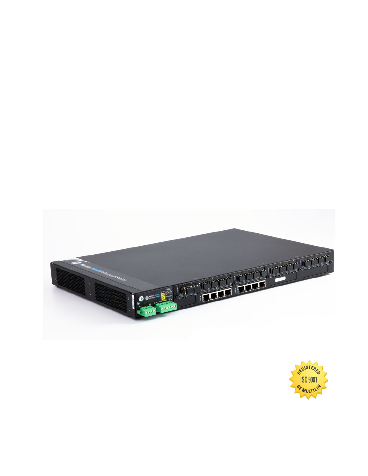
Ethernet Communications Switch
Chapter 1: Introduction
Introduction
1.1 Getting Started
1.1.1 Inspecting the Package and Product
Examine the shipping container for obvious damage prior to installing this product; notify
the carrier of any damage that you believe occurred during shipment or delivery. Inspect
the contents of this package for any signs of damage and ensure that the items listed
below are included.
This package should contain:
• MultiLink ML3000 Ethernet Switch, base unit (configured with user-selected port
module options installed)
• Set of metal “ears” for 19-inch rack mounting
• Installation and user guide (this manual)
Remove the items from the shipping container. Be sure to keep the shipping container
should you need to re-ship the unit at a later date. To validate the product warranty, please
complete and return the enclosed product registration card to GE Multilin as soon as
possible.
In the event there are items missing or damaged, contact the party from whom you
purchased the product. If the unit needs to be returned, please use the original shipping
container if possible. Refer to Troubleshooting on page 4–6, for specific return procedures.
MULTILINK ML3000 ETHERNET COMMUNICATIONS SWITCH – INSTRUCTION MANUAL 1–1
Page 16

INTRODUCTION CHAPTER 1: INTRODUCTION
1.2 Ordering
1.2.1 Order Codes
The following table lists the order codes for the Multilink Ethernet Switch (ML3000). The
fiber optic LC ports are limited to a total of 12.
Table 1–1: ML3000 Order Code Table
ML3000 Slot Mod Description
Gb 100 Mb
1 2 3 4 5 6 7 8 9 10
Base ML3K ML3000 Chassis with Fixed Power Supplies
Mounting F | | | | | | | | | | Front Mounted Ports
B | | | | | | | | | | Rear Mounted Ports
Power Supply HX|||||||||| Single Integrated 90 to 250V AC/DC Power Supply
HH|||||||||| Dual Integrated 90 to 250V AC/DC Power Supplies
LX|||||||||| Single Integrated 22 to 60V DC Power Supply
LL|||||||||| Dual Integrated 22 to 60V DC Power Supplies
P1|||||||||| Single Integrated 22 to 60V DC Power Supply with PoE Support
P2|||||||||| Dual Integrated 22 to 60V DC Power Supply with PoE Support
HL|||||||||| Combination of a 90 to 250V AC/DC and a 22 to 60V DC Power Supply
Modules A A | | | | | | | | 2 x 1000 Mbits RJ-45 Fixed Ports
B B | | | | | | | | 2 x 1000 Mbit SFP, LC Connector, mm Fiber, 550m
C C | | | | | | | | 2 x 1000 Mbit SFP, LC Connector, sm Fiber, 2km
D D | | | | | | | | 2 x 1000 Mbit SFP, LC Connector, sm Fiber, 10km
E E | | | | | | | | 2 x 1000 Mbit SFP, LC Connector, sm Fiber, 25km
F F | | | | | | | | 2 x 1000 Mbit SFP, LC Connector, sm Fiber, 40km
G G | | | | | | | | 2 x 1000 Mbit SFP, LC Connector, sm Fiber, 70km
H H | | | | | | | | 2 x 1000 Mbit SFP ports (no transceivers) empty cage
J J | | | | | | | | 2 x 1000 Mbit RJ-45 Fixed Ports with 1588 timing
K K | | | | | | | | 2 x 1000 Mbit SFP, LC Connector, mm Fiber, 550m with 1588 timing
L L | | | | | | | | 2 x 1000 Mbit SFP, LC Connector, sm Fiber, 2km with 1588 timing
M M | | | | | | | | 2 x 1000 Mbit SFP, LC Connector, sm Fiber, 10km with 1588 timing
N N | | | | | | | | 2 x 1000 Mbit SFP, LC Connector, sm Fiber, 25km with 1588 timing
P P | | | | | | | | 2 x 1000 Mbit SFP, LC Connector, sm Fiber, 40km with 1588 timing
Q Q | | | | | | | | 2 x 1000 Mbit SFP, LC Connector, sm Fiber, 70km with 1588 timing
R R | | | | | | | | 2 x 1000 Mbit SFP ports (no transceivers) empty cage with 1588 timing
X X | | | | | | | | None
A A A A A A A A 4 x 10/100Mbit - RJ45 Copper
B B B B B B B B 4 x 10/100Mbit - RJ45 Copper with PoE*
C C C C C C C C 4 x 10/100Mbit - RJ45 Copper with PoE+*
D D D D D D D D 2 x 10Mbit - ST
E E E E E E E E 2 x 100Mbit - ST mm Fiber
F F F F F F F F 2 x 100Mbit - SC mm Fiber
G G G G G G G G 4 x 100Mbit - LC mm Fiber
1–2 MULTILINK ML3000 ETHERNET COMMUNICATIONS SWITCH – INSTRUCTION MANUAL
Page 17

CHAPTER 1: INTRODUCTION INTRODUCTION
NOTE
Table 1–1: ML3000 Order Code Table
H H H H H H H H 4 x 100Mbit - MTRJ mm Fiber
J J J J J J J J 2 x 100Mbit - SC sm Fiber 20km
K K K K K K K K 4 x 100Mbit - LC sm Fiber 20km
L L L L L L L L 2 x 100Mbit - SC sm Fiber 40km
M M M M M M M M 4 x 100Mbit - LC sm Fiber 40km
N N N N N N N N 4 x 100Mbit SFP ports (no transceivers) empty cage
P P P P P P P P 4 x 10/100Mbit - RJ45 Copper with 1588 Timing
Q Q Q Q Q Q Q Q 2 x 100Mbit - ST mm Fiber with 1588 Timing
R R R R R R R R 2 x 100Mbit - SC mm Fiber with 1588 Timing
S S S S S S S S 4 x 100Mbit - LC mm Fiber with 1588 Timing
T T T T T T T T 4 x 100Mbit - MTRJ mm Fiber with 1588 Timing
U U U U U U U U 4 x 100Mbit - LC sm Fiber 20km with 1588 Timing
W W W W W W W W 2 x 100Mbit - ST sm Fiber 20km with 1588 Timing
Y Y Y Y Y Y Y Y 2 x 100Mbit - SC sm Fiber 20km with 1588 Timing
Z Z Z Z Z Z Z Z 4 x 100Mbit - LC sm Fiber 40km with 1588 Timing
X X X X X X X X None
Environment X None
H Harsh Chemical Environment Conformal Coating
Note
Please refer to the GE Digital Energy website and Online Store for a complete list of
modules and options
MULTILINK ML3000 ETHERNET COMMUNICATIONS SWITCH – INSTRUCTION MANUAL 1–3
Page 18

INTRODUCTION CHAPTER 1: INTRODUCTION
1.3 Specifications
1.3.1 Technical Specifications
PERFORMANCE
Filtering / Forwarding Rate
Ethernet (10 Mb):........................ 14, 880 pps
Fast Ethernet (100 Mb):........... 148, 800 pps
Gigabit Ethernet (1000 Mb):.. 1, 488, 000 pps
Switching processing:............. Store and Forward with IEEE 802.3x full-duplex flow control, non-
blocking
Data rate:......................................10 Mbps, 100 Mbps and 1000 Mbps
Address table capacity:.......... 8 K node, self-learning with address aging
Packet buffer size:..................... 512 KB for 10/100 Mb, 128 KB for Gb
Latency: .........................................6 μs + packet time max. (TX-TX, TX-FX, FX-FX, TX-G, G-G)
System aggregate forward and filter rate:
...........................................................11.9 Mpps
NETWORK STANDARDS AND COMPLIANCE, HARDWARE
Ethernet V1.0/V2.0 IEEE 802.3:
...........................................................10Base-T
IEEE 802.3u:.................................. 100Base-TX, 100Base-FX
IEEE 802.3z: ..................................1000Base-X Ethernet (Auto-negotiation)
IEEE 802.3ab:...............................1000Base-X Ethernet
IEEE 802.1p:.................................. Priority protocol
IEEE 802.1d:.................................. Spanning tree protocol
IEEE 802.1w:................................. Rapid spanning tree protocol
IEEE 802.1q:.................................. VLAN tagging
IEEE 802.3x:.................................. Flow control
IEEE 802.3ad:...............................Link aggregation (Trunking)
IEEE 802.1x:.................................. Port-based network access control
IEEE 802.3af: ................................Power over Ethernet (PoE)
IEEE 1588v2 Timing compliance
IPv6 Compliance
MAXIMUM 10 MBPS ETHERNET SEGMENT LENGTHS
Unshielded twisted pair ......... 100 m (328 ft)
Shielded twisted pair............... 150 m (492 ft)
10Base-FL multi-mode fiber optic
...........................................................2 km (6562 ft)
1–4 MULTILINK ML3000 ETHERNET COMMUNICATIONS SWITCH – INSTRUCTION MANUAL
Page 19

CHAPTER 1: INTRODUCTION INTRODUCTION
MAXIMUM STANDARD FAST ETHERNET SEGMENT LENGTHS
10BASE-T (CAT 3, 4, 5 UTP) .... 100 m (328 ft)
100BASE-TX (CAT 5 UTP)......... 100 m (328 ft)
Shielded twisted pair............... 150 m (492 ft)
100BASE-FX, half-duplex, multi-mode
...........................................................412 m (1350 ft)
100BASE-FX, full-duplex, multi-mode
...........................................................2.0 km (6562 ft)
100BASE-FX, half-duplex, single-mode
...........................................................412 m (1350 ft)
100BASE-FX, full-duplex, single-mode
...........................................................20.0 km (66K ft)
100BASE-FX, full-duplex, Long Reach
...........................................................40.0 km (122K ft)
MAXIMUM STANDARD GIGABIT ETHERNET SEGMENT LENGTHS
1000BASE-T (CAT5e or higher is recommended)
...........................................................100 m (328 ft)
1000BASE-SX, full-duplex, multi-mode (62.5 μm cable)
...........................................................220 m (722 ft)
1000BASE-SX, full-duplex, multi-mode (50 μm cable)
...........................................................550 m (1804 ft)
1000BASE-LX, full-duplex, multi-mode (50, 62.5 μm cable)
...........................................................550 m (1804 ft)
1000BASE-LX, full-duplex, single-mode (9 μm cable)
...........................................................5 km (16.4 K ft)
1000BASE-ZX, full duplex, single-mode (9 μm cable)
...........................................................>70 km (229.6 K ft)
FIBER MULTI-MODE CONNECTOR TYPES SUPPORTED
Fiber Port, LC-type (plug-in):
........................................................... SFF fiber multi-mode 100BASE-FX
Fiber Port, MTRJ-type (plug-in):
........................................................... SFF fiber multi-mode 100BASE-FX
Fiber Port, SC-type (plug-in), multi-mode 100BASE-FX
Fiber Port, ST-type (twist-lock), multi-mode 100BASE-FX
Fiber Port, 1000BASE-SX, SFP modules
FIBER SINGLE-MODE CONNECTOR TYPES
Fiber Port, LC-type, Fiber SFF single-mode, 100BASE-FX
Fiber Port, SC-type, single-mode, 100BASE-FX
Fiber Port, 1000BASE-LX, SFP modules
LEDS
Per Port .......................................... All ports have the following LED designations
L/A=Link/Activity........................ ON=link established
OFF=no link established
BLINKING=link activity
F/H=Full duplex/Half duplex (for copper ports)
...........................................................ON=full duplex mode
OFF=half duplex mode, for copper ports
MULTILINK ML3000 ETHERNET COMMUNICATIONS SWITCH – INSTRUCTION MANUAL 1–5
Page 20

INTRODUCTION CHAPTER 1: INTRODUCTION
DC POWER SUPPLY (INTERNAL, FLOATING GROUND)
DC Power Connector:.............. Terminal block
(L) 24/48VDC Power Input (range 22 to 60V DC)
(H) AC/DC Power Input (range 90-250V AC or DC)
Standard 3-screw Terminal Block: “-, +, GND”
Note: for PoE applications: ...PoE 802.3af: (L) 48V DC Power Input (range 45 to 57V DC)
PoE+ 802.3at: (L) 48V DC Power Input (range 52 to 56V DC)
Standard 2-screw Terminal Block: “-, +"
AC POWER SUPPLY (INTERNAL)
AC Power Connector:...............IEC-320/C14 type, male recessed 100-240 VAC Power Input, 47 to
63 Hz (auto-ranging)
POWER CONSUMPTION
55 watts Max. (for a fully-loaded model with 4 Gb ports, sixteen 100 Mb fiber ports and sixteen RJ-45
10/100 Mb ports)
...........................................................30 watts typical with 32 fully-loaded copper ports
60 watts typical with 32 fully-loaded fiber ports
ALARM RELAY CONTACTS
Max: ................................................. 220 VDC
0.27 A
Form C, One NC indicating internal power, one NC software controllable
MANAGEMENT CONSOLE
Connector.....................................RJ45
1.3.2 Environmental Specifications
OPERATING ENVIRONMENT
Ambient Temperature:............ -40° to 140 °F (-40° to 60 °C) for UL 60950 and Component Parts
Storage Temperature:............. -40° to 185 °F (-40° to 85 °C)
Ambient Relative Humidity: ..5% to 95% (non-condensing)
Altitude:..........................................Up to 6560 feet (2000 m)
Pollution Degree:........................ 2
Conformal Coating (humidity protection) optional:
...........................................................Request quote
1.3.3 Physical Specifications
MOUNTING
Normal standard method (horizontal):
...........................................................suitable for or rack mounting, unit supplied with rack-mounting
rating
-40° to 195 °F (-40° to 85 °C) for IEC 60068 Type Test short term
rating
brackets for mounting in a 19” rack
PACKAGING
Enclosure: .....................................rugged high-strength sheet metal
Dimensions:.................................. 2.63 in H x 17.5 in W x 12.0 in D (6.7 cm H x 44.5 cm W x 30.5 cm D)
COOLING METHOD
Convection, special (patent pending) thermal techniques
1–6 MULTILINK ML3000 ETHERNET COMMUNICATIONS SWITCH – INSTRUCTION MANUAL
Page 21

CHAPTER 1: INTRODUCTION INTRODUCTION
WEIGHT
ML3000 ethernet switch........ 14.2 lbs. (6.5 kg)
1.3.4 Compliance
TEST REFERENCE STANDARD TEST LEVEL
Electrostatic Discharge EN61000-4-2 Level 4
RF immunity EN61000-4-3 Level 3
Fast Transient Disturbance EN61000-4-4 Level 3 & 4
Surge Immunity EN61000-4-5 Level 4
Conducted RF Immunity EN61000-4-6 Level 3
Power magnetic Immunity IEC61000-4-8 Level 3
Voltage Dip & interruption IEC61000-4-11
Ringwave Surge IEC61000-4-12 Level 4
Radiated & Conducted Emissions CISPR22 Class A
Radiated & Conducted Emissions FCC Part 15 Subpart B Class A
Random Vibration EN61373 Class A
Shock EN61373 30g
Safety EN60950-1 standard
Power Interruption NEMA TS2
Power Transients high repetition NEMA TS2 2.1.6.1:2003 300V,2500W
0, 40, 70% dips, 250/300cycle
interrupts
1500 msce, 450 msec
interrupts
Power Transients (low repetition
high energy)
NEMA TS2 2.1.6.2 :2003 600V , 1 ohm impedance
Transients I/O terminals NEMA TS2 2.1.7.1 :2003 300V, 1000 ohms impedance
Non Destructive transient
Immunity
NEMA TS2 2.1.8 :2003 1000V, 1 ohm X 3
Operational frequency NEMA TS2 -57-63Hz 60Hz +/- 3Hz
RF Immunity IEEE C37.90.2 20V/m 80-1Ghz
Trapezoid Surge EN50155 1800 V
Oscillatory Surge IEC61850-3 Level 4 (4 kV)
Harmonic Current Measurement EN61000-3-2 +/- 5%
Voltage Fluctuations and Flicker EN61000-3-3 Standard Limits
Dielectric IEEE 1613 2KV & 500V
Impulse IEEE 1613 5KV
MULTILINK ML3000 ETHERNET COMMUNICATIONS SWITCH – INSTRUCTION MANUAL 1–7
Page 22

INTRODUCTION CHAPTER 1: INTRODUCTION
1.3.5 Approvals
APPLICABLE COUNCIL DIRECTIVE ACCORDING TO
CE Compliance Low voltage directive EN60950-1
EMC Directive EN61000-6-2, EN61000-6-4
North America cULus UL60950-1
C22.2 No. 60950-1
IEC EMI and operating conditions class C for
IEC61850-3
power substations
FCC FCC part 15 subpart B Class A
IEEE IEEE1613 environmental
standard for Electric Power
ISO Manufactured under a registered quality
ISO9001
program
1–8 MULTILINK ML3000 ETHERNET COMMUNICATIONS SWITCH – INSTRUCTION MANUAL
Page 23

CHAPTER 1: INTRODUCTION INTRODUCTION
1.4 Firmware Overview
1.4.1 Command Line Firmware
Commands typed by the user will be shown in the following color and font.
command
The MultiLink Switch Software prompt will be shown in bold and fixed-width text, with a #
> character at the end. The default prompt is indicated as follows:
or
ML3000#
The following hold for syntax rules:
• Syntax rules are italicized
• The command part is in bold
• Optional entries are shown in [square brackets]
• Parameter values within are shown in <pointed brackets>
• Optional parameter values are shown again in [square brackets]
Thus, the syntax
command [parameter1=<value1>[,paramter2=<value2>]]
parameter3=<value3|value4>
indicates the following:
• parameters 1 and 2 are optional
• parameter 2 can be used optionally only if parameter 1 is specified
• parameter 3 is mandatory.
1.4.2 EnerVista Software
Whenever the word PC is used, it implies a UNIX, Linux, Windows, or any other operating
system based workstation, computer, personal computer, laptop, notebook or any other
computing device. Most of the manual uses Windows XP based examples. While effort has
been made to indicate other operating system interactions, it is best to use a Windows-XP
based machine when in doubt.
The documentation reflects features of MultiLink Switch Software version 1.7.x or later. If
your switch is not at the current version, GE Multilin recommends upgrade to version 1.7.x
or later. Please refer to the GE Multilin website for information on upgrading the MultiLink
Switch Software.
Icons common to the EnerVista MultiLink Secure Web Management (SWM) firmware for
edit, delete, save and refresh are:
• Edit - edit the values
• Delete - delete the current row or the value(s)
• Save - save configuration changes
• Refresh - repaint the screen
MULTILINK ML3000 ETHERNET COMMUNICATIONS SWITCH – INSTRUCTION MANUAL 1–9
Page 24

INTRODUCTION CHAPTER 1: INTRODUCTION
1.4.3 Before Starting
This section explains how to setup the GE MultiLink family of switches using the console
port on the switch. Some of the functionality includes setting up the IP address of the
switch, securing the switch with a user name and password, setting up VLANs and more.
Before you start, it is recommended to acquire the hardware listed below and be ready
with the items listed.
For initial configuration through the serial/console port:
1. A female-female null modem cable.
2. A serial port. If your PC does not have a serial port, you may want to invest in
a USB-to-serial converter or USB-to-serial cable.
3. Terminal emulation firmware such as HyperTerminal or other equivalent
firmware. Ensure the firmware supports Xmodem protocol, as you may need
this in the future to update the MultiLink Switch Software.
4. Enough disk space to store and retrieve the configuration files as well as copy
firmware files. We recommend at least 15 MB of disk space for this purpose.
5. For access security - decide on a manager level account name and password
6. IP address, netmask, default gateway for the switch being configured.
As a default, the switch has no IP (Internet Protocol) address and subnet mask. For first
time use, the IP address has to be assigned. This can only be done by using the console
interface provided.
The same procedure can also be used for other configuration changes or updates (for
example, changing the IP address, VLAN assignments and more). Once the IP address is
assigned and a PC is networked to the switch, the switch's command line interface (CLI)
can be accessed via telnet. To manage the switch through in-band (networked) access
(e.g. telnet, or web browser Interface), you should configure the switch with an IP address
and subnet mask compatible with your network. Also, change the manager password to
control access privileges from the console.
Many other features such as optimizing the switch's performance, traffic engineering and
traffic prioritizing, VLAN configuration, and improving network security can be configured
through the switch's console interface as well as in-band (networked) access, once the IP
address is setup. Besides the IP address, setting up the SNMP parameters allows
configuration and monitoring through an SNMP network management station running a
network management program.
1–10 MULTILINK ML3000 ETHERNET COMMUNICATIONS SWITCH – INSTRUCTION MANUAL
Page 25
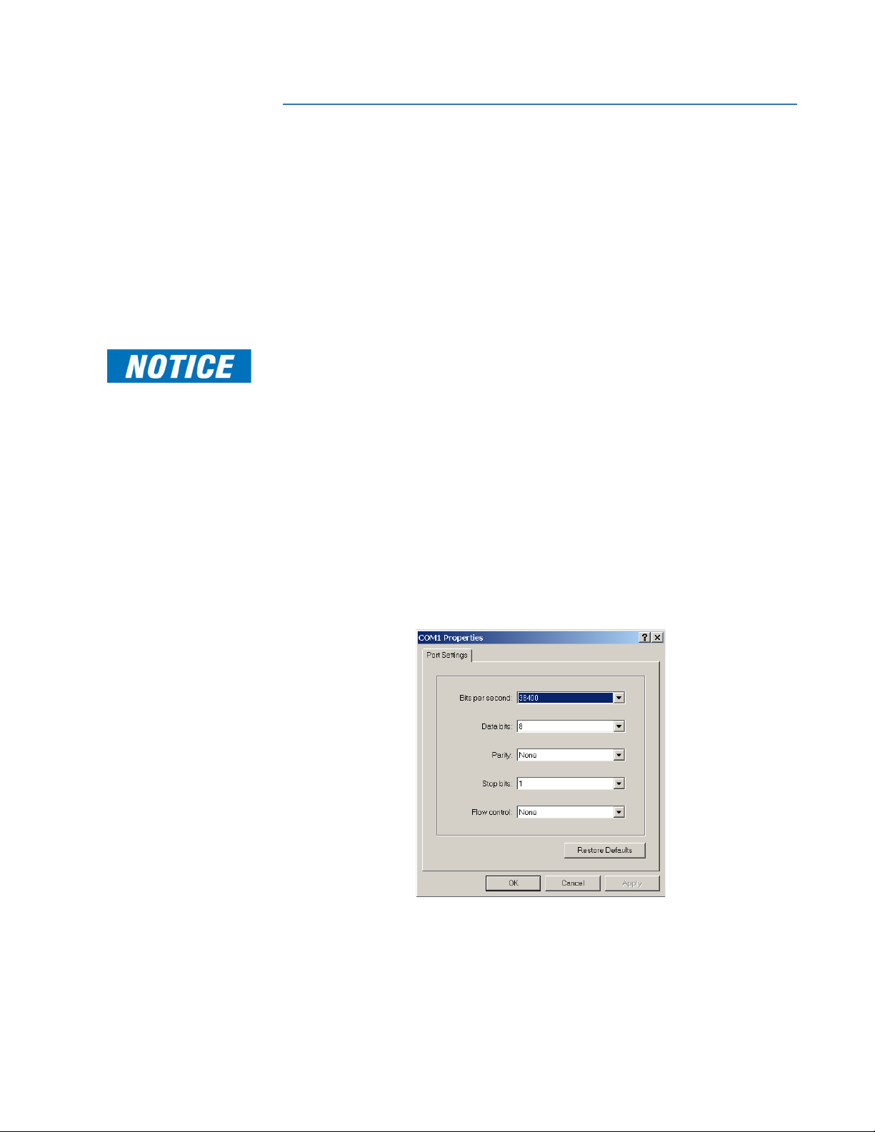
CHAPTER 1: INTRODUCTION INTRODUCTION
1.5 Command Line Interface Firmware
1.5.1 Console Connection
The connection to the console is accessed through the DB-9 RJ45connector on the switch
marked as the console port. This command line interface (or CLI) provides access to the
switch commands. It can be accessed by attaching a PC running terminal emulation
firmware to the console port.
USB-to-RJ45 adapters are also available for computers that have access to USB ports.
The interface through the console or the console management interface (or CMI) enables
you to reconfigure the switch and to monitor switch status and performance.
Note
1.5.2 Console Setup
Once the switch is configured with an IP address, the command line interface (or CLI) is
also accessible using telnet as well as the serial port. Access to the switch can be either
through the console interface or remotely over the network. Simultaneous access (that is,
through the console port as well as through the network) to the MultiLink switch is not
permitted.
The Command Line Interface (CLI) enables local or remote unit installation and
maintenance. The MultiLink family of switches provides a set of system commands which
allow effective monitoring, configuration and debugging of the devices on the network.
Connect the console port on the switch to the serial port on the computer using the serial
cable listed above. The settings for the HyperTerminal firmware are shown below. Make
sure the serial parameters are set as shown (or bps = 38400, data bits = 8, parity = none,
stop bits = 1, flow control = none).
FIGURE 1–1: Serial Settings in HyperTerminal
1.5.3 Console Screen
Once the console cable is connected to the PC and the firmware configured, ML3000 legal
disclaimers and other text scrolls by on the screen.
MULTILINK ML3000 ETHERNET COMMUNICATIONS SWITCH – INSTRUCTION MANUAL 1–11
Page 26

INTRODUCTION CHAPTER 1: INTRODUCTION
NOTE
The line interface prompt appears displaying the switch model number (e.g. ML3000>)
The switch has three modes of operation: operator (least privilege), manager, and
configuration. The prompts for the switches change as the switch changes modes from
operator to manager to configuration. The prompts are shown below with a brief
description.
• ML3000>
Operator Level - for running operations queries
• ML3000#
Manager Level - for setting and reviewing commands
• ML3000##
Configuration Level - for changing the switch parameter values
For additional information on default users, user levels and more, refer to User
Management on page 1–15.
1.5.4 Logging In for the First Time
For the first time, use the default user name and passwords assigned by GE. They are:
•Username: manager
Password: manager
•Username: operator
Password: operator
We recommend you login as manager for the first time to set up the IP address as well as
change user passwords or create new users.
1.5.5 Automatic IP Address Configuration
The ML3000 is operational immediately after it is powered up. The advanced management
and configuration capabilities of the ML3000 allows you to easily configure, manage, and
secure your devices and network.
Before starting, ensure you have the following items:
• RJ45 Ethernet cable
•PC with an Ethernet port
• Microsoft Internet Explorer 6.0 or higher
• Macromedia Flash Player 5.0 or higher (available from http://
www.macromedia.com/shockwave/download/
download.cgi?P1_Prod_Version=ShockwaveFlash)
Ensure both firmware components are installed before proceeding.
The ML3000 can search the network for commonly used services that can issue an IP
address. If the switch is connected to a network, the ML3000 uses the following process to
find an IP address.
Note
If the ML3000 is not connected to a network, then proceed to Step 3 below. or use the
default IP address.
Step 1:
The ML3000 will scan the network for a DHCP server. If the server responds, the ML3000
will acquire and set the assigned IP address. To manage the switch, determine the
assigned IP address and enter as follows in Internet Explorer:
1–12 MULTILINK ML3000 ETHERNET COMMUNICATIONS SWITCH – INSTRUCTION MANUAL
Page 27

CHAPTER 1: INTRODUCTION INTRODUCTION
https://<assigned_IP_address>
Ensure that https is entered, not http, and that there is connectivity (that is, you can ping
the switch).
tep 2:
S
If there is no response from a DCHP server, the ML3000 will query for a BOOTP server. If the
server responds, the ML3000 will acquire and set the assigned IP address. To manage the
switch, determine the assigned IP address and enter as follows in Internet Explorer:
<assigned_IP_address>
https://
Ensure that https is entered, not http, and that there is connectivity (that is, you can ping
the switch).
Step 3:
If there is no response from either a DCHP or BOOTP server, or if the switch is not
connected to a network, the switch will assign itself an IP address. The ML3000 will check
to see if IP address 192.168.1.2, with a network mask of 255.255.255.0, is free. If so, it will
assume these values. If this IP address is assigned to another device, the ML3000 will
repeat steps 1 through 3 to find a DCHP or BOOTP server or wait for the 192.168.1.2
address to become free.
Once connected, the browser will display a login prompt. The default login is:
•Username: manager
Password: manager
1.5.6 Setting the IP Parameters
To setup the switch, the IP address and other relevant TCP/IP parameters have to be
specified.
The IP address on the MultiLink switch is set to 192.168.1.2 from the factory. The switch is
fully operational as a Layer 2 switch as a default. Setting a default IP address can
potentially cause duplicate IP address problem if multiple switches are powered on and
installed on the network. To manage the switch, an IP address has to be programmed.
Before starting, please ensure that the IP address assigned to the switch is known or
contact your system/network administrator to get the IP address information. Follow the
steps listed below to configure the switch.
Ensure the power is off.
Follow the steps described above for connecting the console cable
and setting the console firmware.
Power on the switch.
Once the login prompt appears, login as manager using default
password (manager).
Configure the IP address, network mask and default gateway as per
the IP addressing scheme for your network.
Set the manager password (this step is recommended; refer to the
following section).
Save the settings (without saving, the changes made will be lost).
Power off the switch (or a firmware reboot as discussed below).
Power on the switch - login with the new login name and password.
MULTILINK ML3000 ETHERNET COMMUNICATIONS SWITCH – INSTRUCTION MANUAL 1–13
Page 28

INTRODUCTION CHAPTER 1: INTRODUCTION
NOTE
From the PC (or from the switch) ping the IP address specified for the
switch to ensure connectivity.
From the switch ping the default gateway specified (ensure you are
connected to the network to check for connectivity) to ensure
network connectivity.
Syntax:
ipconfig [ip=<ip-address>] [mask=<subnet-mask>] [dgw=<gateway>]
An example is shown below.
ML3000# ipconfig ip=3.94.247.41 mask=255.255.252.0
dgw=3.94.247.41
ML3000# save
Note
This manual assumes the reader is familiar with IP addressing schemes as well as how net
mask is used and how default gateways and routers are used in a network.
Reboot gives an opportunity to save the configuration prior to shutdown. For a reboot,
simply type in the command
reboot. Note that even though the passwords are not
changed, they can be changed later.
ML3000# reboot
Proceed on rebooting the switch? ['Y' or 'N'] Y
Do you wish to save current configuration? ['Y' or 'N'] Y
ML3000#
The ML3000 forces an answer by prompting with a “Y” or a “N” to prevent accidental
keystroke errors and loss of work.
The parameters can be viewed at any time by using the
show command. The show
command will be covered in more detail later in various sections throughout the
document.
The example below illustrates the basic setup parameters. You can use
show setup or
show sysconfig commands to view setup parameters.
ML3000# show setup
Version: ML3000 build 1.6.1 Apr 29 2005 11:10:13
MAC Address: 00:20:06:27:0a:e0
IP Address: 3.94.247.41
Subnet Mask: 255.255.252.0
Gateway Address: 3.94.244.1
CLI Mode: Manager
System Name: ML3000
System Description: 25 Port Modular Ethernet Switch
System Contact: multilin.tech@ge.com
System Location: Markham, Ontario
System ObjectId: 1.3.6.1.4.1.13248.12.7
ML3000# show sysconfig
System Name: ML3000
System Contact: multilin.tech@ge.com
System Location: Markham, Ontario
Boot Mode: manual
Inactivity Timeout(min): 120
Address Age Interval(min): 300
Inbound Telnet Enabled: Yes
Web Agent Enabled: Yes
1–14 MULTILINK ML3000 ETHERNET COMMUNICATIONS SWITCH – INSTRUCTION MANUAL
Page 29

CHAPTER 1: INTRODUCTION INTRODUCTION
Time Zone: GMT-05hours:00minutes
Day Light Time Rule: Canada
System UpTime: 0 Days 0 Hours 45 Mins 55 Secs
ML3000#
Some of the parameters in the MultiLink family of switches are shown above. The list of
parameters below indicates some of the key parameters on the switch and the
recommendations for changing them (or optionally keeping them the same).
1.5.7 Privilege Levels
Two privilege levels are available - manager and operator. Operator is at privilege level 1
and the manager is at privilege level 2 (the privilege increases with the levels). For example,
to set up a user for basic monitoring capabilities use lower number or operator level
privilege (level 1).
The Manager level provides all operator level privileges plus the ability to perform systemlevel actions and configuration commands. To select this level, enter the
name> command at the Operator level prompt and enter the Manager password, when
prompted.
enable <user-name>
For example, switching from an operator-level to manager-level, using the
command is shown below.
ML3000> enable manager
Password: *******
ML3000#
Note the prompt changes with the new privilege level.
Operator privileges allow views of the current configurations but do not allow changes to
the configuration. A “>” character delimits the operator-level prompt.
Manager privileges allow configuration changes. The changes can be done at the
manager prompt or for global configuration as well as specific configuration. A “#”
character delimits any manager prompt.
enable <user-
enable
1.5.8 User Management
A maximum of five users can be added per switch. Users can be added, deleted or
changed from a manager level account. There can be more than one manager account,
subject to the maximum number of users on the switch being restricted to five.
To add a user, use the
name. The password is recommended to be at least 8 characters long with a mix of upper
case, lower case, numbers and special characters.
add user=<name> level=<number>
The following example adds a user “peter” with manager-level privilege:
ML3000# user
ML3000(user)## add user=peter level=2
Enter User Password:******
Confirm New Password:******
ML3000(user)##
To delete a user, use the delete command as shown below.
delete user=<name>
MULTILINK ML3000 ETHERNET COMMUNICATIONS SWITCH – INSTRUCTION MANUAL 1–15
add command as shown below. The user name has to be a unique
Page 30

INTRODUCTION CHAPTER 1: INTRODUCTION
The following example deletes the user “peter”:
ML3000(user)## delete user=peter
Confirm User Deletion(Y/N): Y
User successfully deleted
ML3000(user)##
The syntax to modify a password is shown below:
passwd user=<name>
The following example changes the password for user “peter”.
ML3000(user)## passwd user=peter
Enter New Password:******
Confirm New Password :******
Password has been modified successfully
ML3000(user)##
The syntax to modify the privilege level for a specific user is shown below:
chlevel user=<name> level=<number>
The following example modifies the privilege level of user “peter” to Operator privileges.
ML3000(user)## chlevel user=peter level=1
Access Permission Modified
ML3000(user)##
The syntax to set the access privileges for telnet and Web services is shown below:
useraccess user=<name> service=<telnet|web> <enable|disable>
The following example sets the access privileges for telnet and Web services.
ML3000(user)## useraccess user=peter service=telnet disable
Telnet Access Disabled.
1.5.9 Help
Typing the help command lists the commands you can execute at the current privilege
level. For example, typing
ML3000> help
logout ping set
terminal telnet walkmib
Contextless Commands:
! ? clear
enable exit help
show whoami
alarm
ML3000>
Help for any command that is available at the current context level can be viewed by
typing help followed by enough of the command string to identify the command. The
following syntax applies:
help <command string>
1–16 MULTILINK ML3000 ETHERNET COMMUNICATIONS SWITCH – INSTRUCTION MANUAL
help at the Operator level shows the following:
Page 31

CHAPTER 1: INTRODUCTION INTRODUCTION
For example, to list the help for the set time command
ML3000# help set time
set time : Sets the device Time
Usage
set time hour=<0-23> min=<0-59> sec=<0-59> [zone=GMT[+/-]hh:mm]
ML3000#
The options for a specific command can be displayed by typing the command and
pressing enter. The following syntax applies:
command <Enter>
For example, the options for the
ML3000# show <Enter>
Usage
show active-stp
show active-snmp
show active-vlan
show address-table
show age
show alarm
show arp
show auth <config|ports>
show backpressure
show bootmode
--more--
show command are:
Other ways to display help, specifically, with reference to a command or a set of
commands, use the TAB key. The following syntax applies:
<TAB>
<Command string> <TAB>
<First character of the command> <TAB>
For example, following the syntax listed above, the <TAB> key will list the available
commands in the particular privilege level:
ML3000> <TAB>
?
alarm
clear
enable
exit
help
logout
ping
set
show
telnet
terminal
walkmib
whoami
ML3000>
MULTILINK ML3000 ETHERNET COMMUNICATIONS SWITCH – INSTRUCTION MANUAL 1–17
Page 32

INTRODUCTION CHAPTER 1: INTRODUCTION
The following example lists commands starting with a specific string:
ML3000> s <TAB>
set
show
ML3000>
In the following example, the <TAB> key completes the command:
ML3000> se<TAB>
password
timeout
vlan
ML3000> set
1.5.10 Exiting
To exit from the CLI interface and terminate the console session use the logout
command. This command prompts to ensure that the logout was not mistakenly typed.
The following syntax applies:
logout
The following example illustrates logging out from a session:
ML3000> logout
Logging out from the current session [’Y’ or ’N’] Y
Connection to the host lost
1–18 MULTILINK ML3000 ETHERNET COMMUNICATIONS SWITCH – INSTRUCTION MANUAL
Page 33

CHAPTER 1: INTRODUCTION INTRODUCTION
NOTE
1.6 EnerVista Secure Web Management
1.6.1 Logging in for the First Time
Enter the following URL in the web browser to login to the EnerVista Secure Web
Management software.
https://<IP Address assigned to the switch>
Note
Make sure you use HTTPS (secure HTTP) and not HTTP in the URL.
In the example shown in the previous section, the URL is:
https://3.94.247.41
If your site uses name services, you can use a name instead of the IP address. Please make
sure that the name is resolved to the IP address assigned to the switch.
The secure site will issue the certificate check shown below.
FIGURE 1–2: Security certificate
Once you click Yes on the security certificate, the browser will prompt you to login.
FIGURE 1–3: Login screen
MULTILINK ML3000 ETHERNET COMMUNICATIONS SWITCH – INSTRUCTION MANUAL 1–19
Page 34
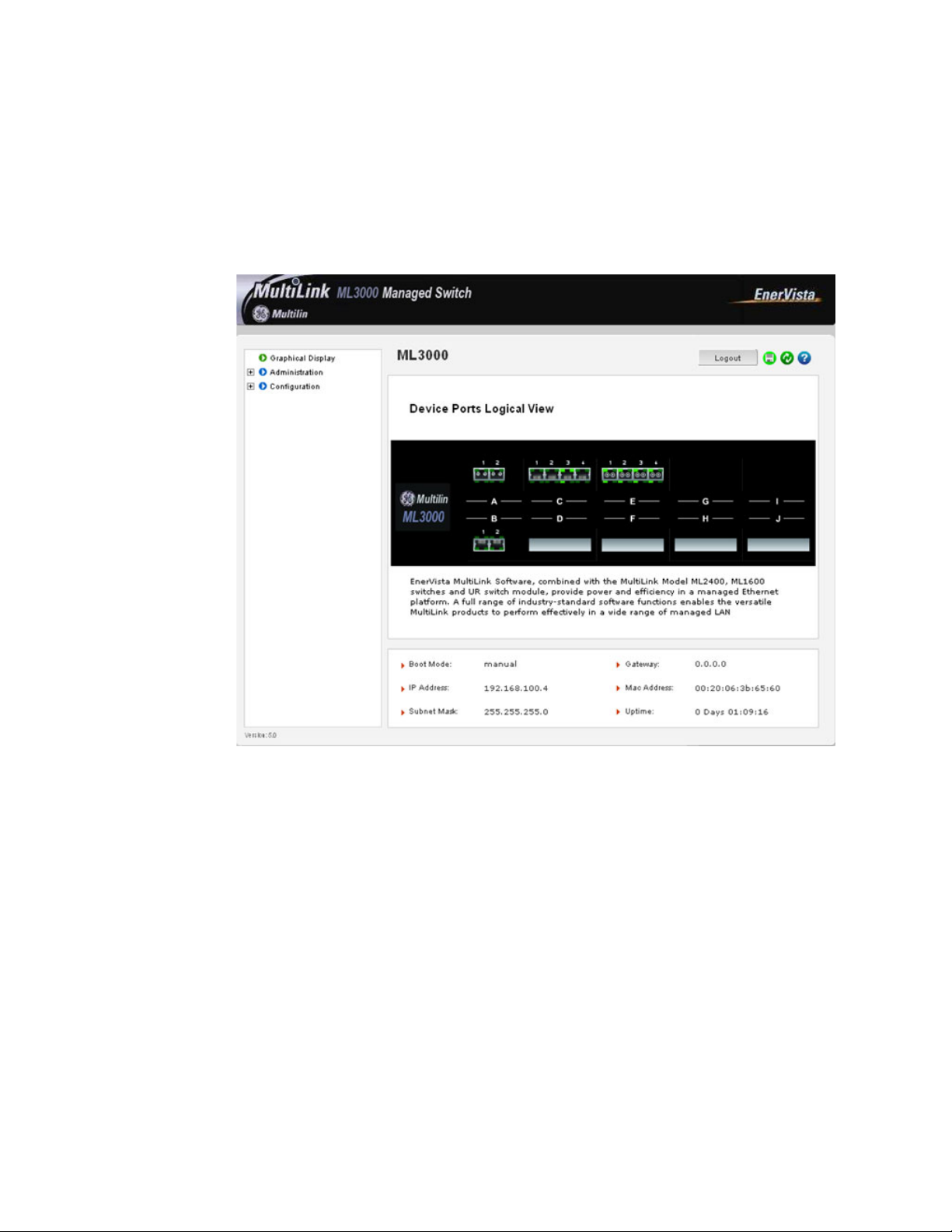
INTRODUCTION CHAPTER 1: INTRODUCTION
For the first time,
Login with the name manager and password manager.
Click on Login.
After a successful login, the welcome screen is shown. Note the different information
provided on the screen and different areas. The menus are used to configure settings on
the switch. Users can click on a specific port to open the port configuration view.
FIGURE 1–4: Welcome screen
1.6.2 Privilege Levels
• Operator privilege users: operator privileges allow views of the current
configurations but do not allow changes to the configuration.
• Manager privilege users: manager privileges allow configuration changes. The
changes can be done at the manager prompt or for global configuration as well as
specific configuration.
1.6.3 User Management
A maximum of five users can be added per switch. Users can be added, deleted or
changed from a manager level account. There can be more than one manager account,
subject to the maximum number of users on the switch being restricted to five.
Select the Administration > User Mgmt > User Accounts menu
item.
1–20 MULTILINK ML3000 ETHERNET COMMUNICATIONS SWITCH – INSTRUCTION MANUAL
Page 35
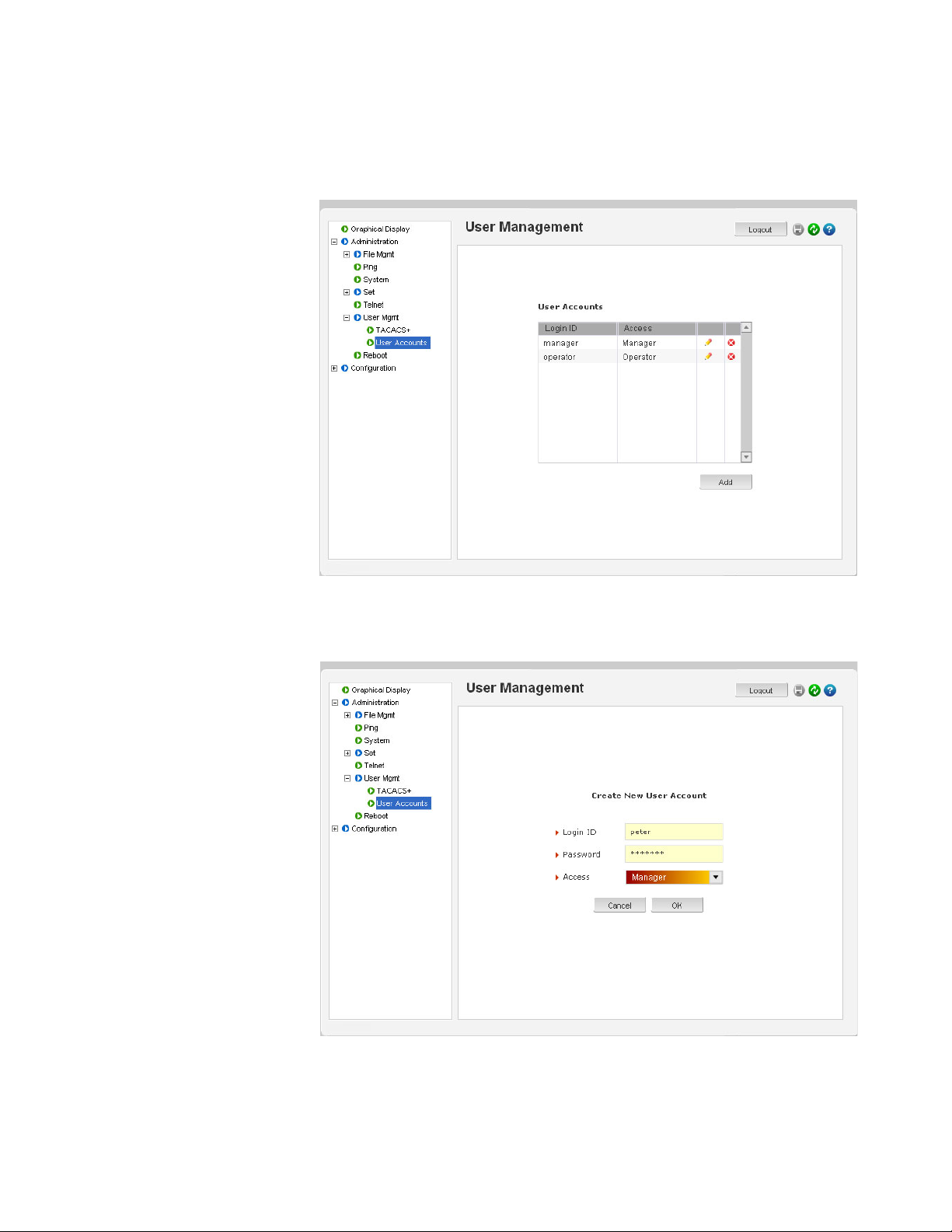
CHAPTER 1: INTRODUCTION INTRODUCTION
To add a user, use the add button.
The username must be a unique name. The password is recommended to be at least 8
characters long with a mix of upper case, lower case, numbers and special characters.
In the following example below, the user peter was added with manager privilege after
clicking the add button.
MULTILINK ML3000 ETHERNET COMMUNICATIONS SWITCH – INSTRUCTION MANUAL 1–21
Page 36

INTRODUCTION CHAPTER 1: INTRODUCTION
After successfully adding a user, the added user is displayed in the list of users as shown
below.
To delete a user, click on the delete icon ( )as shown below.
1–22 MULTILINK ML3000 ETHERNET COMMUNICATIONS SWITCH – INSTRUCTION MANUAL
Page 37

CHAPTER 1: INTRODUCTION INTRODUCTION
The firmware will prompt to verify the delete command.
To modify the password, view the users as described above and click
on the edit icon ( ).
MULTILINK ML3000 ETHERNET COMMUNICATIONS SWITCH – INSTRUCTION MANUAL 1–23
Page 38

INTRODUCTION CHAPTER 1: INTRODUCTION
After clicking on the edit icon, the screen opens up for modifying the password.
In this example, the user ID peter was selected for modification. The password for peter
will be modified after the new password is entered.
1.6.4 Modifying the Privilege Level
Privilege levels cannot be changed from the EnerVista Secure Web Management (SWM)
firmware. This can only be done through the CLI interface, or alternately, by deleting the
user and adding the same user with the proper privilege level.
1–24 MULTILINK ML3000 ETHERNET COMMUNICATIONS SWITCH – INSTRUCTION MANUAL
Page 39

CHAPTER 1: INTRODUCTION INTRODUCTION
1.6.5 Help
Help for the EnerVista Secure Web Management software can be obtained by clicking on
the Help icon as shown below.
MULTILINK ML3000 ETHERNET COMMUNICATIONS SWITCH – INSTRUCTION MANUAL 1–25
Page 40
INTRODUCTION CHAPTER 1: INTRODUCTION
1.6.6 Exiting
To exit or logout, click on the logout button.
Confirm the logout by selecting OK in the pop-up window.
1–26 MULTILINK ML3000 ETHERNET COMMUNICATIONS SWITCH – INSTRUCTION MANUAL
Page 41

CHAPTER 1: INTRODUCTION INTRODUCTION
1.7 ML3000 Firmware Updates
1.7.1 Updating MultiLink Firmware
This section describes how to upgrade the firmware on a Multilink switch, either locally at
the console port or remotely over the network using FTP or TFTP. Depending on the update
process (serial/console port or network), ensure the necessary tools listed below are
available, tested and working before you begin.
For serial port updates directly through the serial/console port, the following items are
required.
1. A female-to-female null modem cable.
2. A USB-to-serial converter or cable if your PC does not have a serial port. A
cable is available from GE Multilin.
3. Terminal emulation firmware such as HyperTerminal (included with Windows)
or equivalent. Ensure that the firmware supports the Xmodem protocol
4. At least 15 MB of free disk space.
5. Manager level account name and password of the switch being upgraded.
6. An internet connection. Ensure the connection does not block ftp file transfers
1.7.2 Selecting the Proper Version
Ensure that the proper version of the MultiLink Switch Software is installed. The latest
version of the firmware is available at http://www.GEmultilin.com.
Connect to the ML3000 and login as manager.
Enter the
Download the latest version of MultiLink firmware from the GE
1.7.3 Updating through the Command Line
Use the following procedure to install firmware to the ML3000 via the serial port.
Download the MultiLink Switch Software from the GE Multilin web
Use the null-modem cable to connect to the ML3000 serial port.
Login at the manager level with the proper password.
Save the existing configuration (refer to Saving Configuration on
show version command.
Multilin website.
site.
page 5–20 for details).
Enter the following command:
ML3000# xmodem get type=app
Do you wish to upgrade the image? [Y or N] Y
Please start XModem file transfer now.
Refer to Saving Configuration on page 5–20 for details on the xmodem command.
MULTILINK ML3000 ETHERNET COMMUNICATIONS SWITCH – INSTRUCTION MANUAL 1–27
Page 42
INTRODUCTION CHAPTER 1: INTRODUCTION
Once the upgrade is started, the terminal emulation firmware will ask for the installation
file location.
Indicate the file location to begin the file transfer.
Make sure the Xmodem protocol is also selected in this file location
dialog window.
In some operating systems it maybe necessary to select the transfer option.
In this case,
Return to the HyperTerminal window used in step 5.
Select the Transfer > Send File menu item.
As shown below, enter the location of the new firmware file.
Select the Xmodem protocol.
Select the Send button and to begin the file transfer.
Once the file transfer is completed reboot the switch with the
reboot command or by cycling power.
Login to the switch and use the
show version command to verify
and upload the configuration file (if necessary).
1.7.4 Updating through the enervista Software
Use the following procedure to install the EnerVista Secure Web Management software.
Download the latest MultiLink firmware from the GE Multilin web site.
1–28 MULTILINK ML3000 ETHERNET COMMUNICATIONS SWITCH – INSTRUCTION MANUAL
Page 43

CHAPTER 1: INTRODUCTION INTRODUCTION
Save this file on FTP or TFTP. Ensure the FTP or TFTP path is
configured. If using FTP, record the FTP login name and password.
Select the switch to upgrade. Ensure you have system administration
privileges available on the switch.
Open a EnerVista Secure Web Management software session with
the switch by typing in the following URL:
https://<IP address of the switch>
If using FTP, save the configuration before proceeding. GE Multilin recommends a two-step
update: first save the configuration to the ftp server, then load the new image and restart
the switch (refer to Saving Configuration on page 5–20 for details on saving the
configuration).
Load the new firmware as shown below.
As the file is being loaded, the firmware will display the transfer in progress window.
Reboot the switch when the transfer is complete.
After reboot, the firmware is ready for use.
If using TFTP, save the configuration before proceeding.
GE Multilin recommends a two-step update:
MULTILINK ML3000 ETHERNET COMMUNICATIONS SWITCH – INSTRUCTION MANUAL 1–29
Page 44

INTRODUCTION CHAPTER 1: INTRODUCTION
• first save the configuration to the TFTP server,
• then load the new image and restart the switch (refer to Saving
Configuration on page 5–20 for details on saving the
configuration).
Load the new firmware as shown below.
As the file is being loaded, the firmware will display the transfer in progress window.
Reboot the switch when the transfer is complete.
After reboot, the firmware is ready for use.
1–30 MULTILINK ML3000 ETHERNET COMMUNICATIONS SWITCH – INSTRUCTION MANUAL
Page 45

GE Energy
Multilink ML3000
Ethernet Communications Switch
Chapter 2: Product Description
Product Description
2.1 Overview
2.1.1 Introduction to the ML3000
The Multilink ML3000 Ethernet Switch provides rack-mount space efficiency and advanced
port configurability for heavy duty industrial applications where maximum fiber port count
and diversity are required. New advanced thermal design techniques (patent pending)
enable the ML3000 to deliver high reliability and configurability even at extended
operating temperatures. Special rack-mount cooling features include Thermal Fins for
extra heat dissipation and internal heat transfer techniques that use the case as a heat
sink. Cooler operation of internal electronic components leads to longer life-time and
increased reliability.
Next-Generation industrial switch features, especially for power utility facilities in the
Smart Grid, importantly include high precision IEEE 1588v2 timing synchronization with
precision as low as single-digit nanoseconds. The ML3000 provides an advanced level of
1588v2 timing features and accuracy, using integrated hardware and software. Advanced
timing is supported on 100 Mb and Gb ports, and is configurable on both fiber and copper
port types.
The ten port slots in the ML3000 provide the configuration flexibility for network designers
to choose up-to four fiber or copper Gb ports, and up-to thirty-two 100 Mb SFF fiber or
copper ports. Copper ports can optionally be Power-Sourcing PoE. Modules may be
configured for regular port types: PoE, IEEE 1588v2 Timing, or combinations.
ML3000 Managed Switches come with field-proven Management Software. Management
Software features include LAN software support including SNMP management, IPv6,
Secure Web Management, IGMP, graphical user interface (GUI), redundant LANs support,
and many network management security and ease-of-use features.
ML3000 Managed Switches have rugged metal cases for regular or“Reverse” rackmounting, and auto-ranging power supplies for operation with standard AC power
worldwide, or DC power input choices. Moisture and corrosion-protecting Conformal
Coating is optional.
MULTILINK ML3000 ETHERNET COMMUNICATIONS SWITCH – INSTRUCTION MANUAL 2–1
Page 46

PRODUCT DESCRIPTION CHAPTER 2: PRODUCT DESCRIPTION
2.1.2 Design Aspects
Designed for use in network traffic centers, the MultiLink ML3000 Ethernet Switch is easy to
install and use. Addresses of attached nodes are automatically learned, maintained, and
aged out, adapting the switching services to network changes. LEDs provide status
information on each port. The ML3000 provides high performance plug-and-play
hardware operation, 802.1p packet prioritization in hardware, and industry-standard
managed networks software functionality, all in convenient 1 U rack-mount packages.
The ML3000 is a 19" rack-mountable Ethernet switch with three eight-port slots (A, B, and
C) and one Gb-only slot (D). Slots A, B and C may be configured with a selection of fiber and
copper ports. Slot D may be configured with a Gb module that accepts GBICs. These
configurable ports allow the ML3000 to efficiently serve a large variety of applications. The
ML3000 modules are usually factory installed, but may be changed or added at a later
date in the field.
Status LEDs are part of each port module and are viewable when connecting the Ethernet
media. The port status data is also accessible through the MultiLink Switch Software.
2–2 MULTILINK ML3000 ETHERNET COMMUNICATIONS SWITCH – INSTRUCTION MANUAL
Page 47

CHAPTER 2: PRODUCT DESCRIPTION PRODUCT DESCRIPTION
NOTE
Power Indicator
(Illuminated when power is supplied to the internal switch)
Link indicators
(Illuminated when
Link is established
to that port)
2.2 ML3000 Modules
An important feature of the ML3000 is the use of Port Modules for flexible mixed-media
connectivity to RJ-45 copper and various fiber media. The first two slots (A & B) of the
Magnum 10KT Switch are fixed RJ-45 auto-negotiating copper ports or SFP (Small Form
Pluggable) fiber ports with 1000Mbps capability. Additionally, the switch can accept up to
eight additional Port Modules in slots C-J to provide the user with up to 32 additional ports
providing a wide selection of Ethernet copper and fiber media connections with 10 and
100Mbps capability.
Note
The ML3000 Port Modules are not identical to the port modules used in other Multilink
ML2400 switch products. For information about other General Electric products, please see
the applicable product manual. For a list of ML3000 Modules, refer to Section 1.2.1: Order
Codes.
Each ML3000 Port Module is individually described in the following sections.
2.2.1 ML3000 Module LED designations
All ports have the following LED designations:
• L/A = Link / Activity
• Off (No Link established)
• ON (Link established)
• BLINKING (Link Activity)
• F/H = Full Duplex / Half Duplex (for Copper ports)
•ON (Full Duplex)
• OFF (Half Duplex) for Copper port
MULTILINK ML3000 ETHERNET COMMUNICATIONS SWITCH – INSTRUCTION MANUAL 2–3
FIGURE 2–1: LED Indicators
Page 48

PRODUCT DESCRIPTION CHAPTER 2: PRODUCT DESCRIPTION
NOTE
2.2.2 Module A (100Mb) - four RJ45 ports (use in Slots 3-10)
The Module A four-port copper module provides four 10/100Mb switched RJ-45 ports. The
10/100Mb switched ports normally (as a default setting) are independently N-way autonegotiating and auto-crossover (MDIX) for operation at 10 or 100Mb speed in full- or halfduplex mode. (i.e., each independently selects a mode and speed to match the device at
the other end of the twisted pair cable).
FIGURE 2–2: Module A, 100 Mb - four RJ45 ports
For auto-negotiation and MDIX details, see Section 4.1.6.
There are two LEDs per RJ-45 port on the module; one for Link/Activity and one for F/H
Duplex. For the Module A LED designations, see Section 2.2.1: ML3000 Module LED
designations.
A twisted pair cable must be connected into an RJ-45 port and the Link (L/A) indicator for
that port must be ON (indicating there is a powered-up device at the other end of the
cable) in order for the L/A LED to provide valid indications of operating conditions on that
port.
Using the Multilink ML3000 software, the user may disable auto-negotiation and fix the
desired operation of each RJ-45 port. The user may select 10Mb or 100Mb speed and fullor half-duplex mode per-port as required.
A module similar to Module A is also available with IEEE 1588v2 Timing Synchronization as
Module P.
Note
For Power Substations: In support of the IEEE 1613 Class 2 standard, GCI advises that, for
substation applications, the RJ-45 ports are intended for connectivity to other
communication equipment such as routers or telecommunication multiplexers installed in
close proximity (i.e., less than 2 meters or 6.5 ft) to the 10KT. It is not recommended to use
these ports in substation applications to interface to field devices across distances which
could produce high (greater than 2500 V ) levels of ground potential rise (GPR) during lineto-ground fault conditions. The 10KT passes the 1613 specifications for zero packet loss
with fiber ports and with RJ-45 ports used as indicated here.
2.2.3 Module G (100 Mb) - four Multimode LC (use in Slots 3-10)
The Module G four-port fiber module provides four 100Mb Multimode LC Fiber ports.
FIGURE 2–3: Module G, 100 Mb - four Multimode LC
2–4 MULTILINK ML3000 ETHERNET COMMUNICATIONS SWITCH – INSTRUCTION MANUAL
Page 49

CHAPTER 2: PRODUCT DESCRIPTION PRODUCT DESCRIPTION
The Module G fiber ports are Small Form Factor (SFF) LC Multimode connectors used
primarily in 100Mbps fiber-to-IED links in industrial applications. When installed in an
ML3000, it supports fiber optic cable distances up to the IEEE-standard 100Mbps distance
limits, i.e., typically 2 km at full-duplex and 412 m at half-duplex.
The compact size of the LC Connector reduces the size of wiring panels in wiring closets
while providing the advantage of "future-proof" fiber optic technology.
The cable end is a "plug-in" connector with both fiber strands terminated in one housing
that cannot be improperly inserted. Each port has a Link/Activity (L/A) LED indicating
proper connectivity (Link) with the remote device when lit and blinking (Activity), indicating
packets being received.
A module similar to Module G is also available with IEEE 1588v2 Timing Synchronization as
Module S.
2.2.4 Module K, Module M (100 Mb) - four Singlemode LC (use in Slots 3-10)
The Module K 4-port Fiber module provides four 100Mb Singlemode LC Fiber ports,
supporting distances up to 20km. This module provides the same functions as the
Multimode version (see Section 2.2.3 for more details).
The Module M 4-port Fiber module provides four 100Mb Singlemode LC (Long Reach) Fiber
ports, supporting distances up to 40km. This module provides the same functions as the
Multimode version (see Section 2.2.3 for more details).
Modules similar to Module K and Module M are also available with IEEE 1588v2 Timing
Synchronization as Module U and Module Z.
2.2.5 Module H (100 Mb) - four Multimode MTRJ (use in Slots 3-10)
The Module H four-port fiber module provides four 100Mb Multimode MTRJ Fiber ports.
FIGURE 2–4: Module H, 100 Mb - four port fiber module
The Module H fiber port is a Small Form Factor (SFF) MTRJ Multimode connector. The
MTRJ's small size and ease of connection make it a good choice for 100Mbps "fiber-to-thedesktop" Ethernet connectivity. When installed in a Magnum 10KT Series Switch, it
supports fiber optic cable distances up to the IEEE-standard 100Mbps distance limits, i.e.,
typically 2km at full-duplex and 412m at half-duplex.
The cable end is a "plug-in" connector with both fiber strands terminated in one housing
that cannot be improperly inserted. Each port has a Link/Activity (L/A) LED indicating
proper connectivity (Link) with the remote device when lit and blinking (Activity), indicating
packets being received.
A module similar to Module H is also available with IEEE 1588v2 Timing Synchronization as
Module T.
MULTILINK ML3000 ETHERNET COMMUNICATIONS SWITCH – INSTRUCTION MANUAL 2–5
Page 50
PRODUCT DESCRIPTION CHAPTER 2: PRODUCT DESCRIPTION
2.2.6 Module F, Module E (100 Mb) - (use in Slots 3-10) Two SC Multimode or two ST Multimode
The Module F (shown) two-port fiber module provides two 100Mb Multimode SC Fiber
ports. This option utilizes a SC-type "push-pull" fiber optic connection.
FIGURE 2–5: Module F - Upper Port module (slots 3, 5, 7, 9)
FIGURE 2–6: Module F - Lower Port module (slots 4, 6, 8, 10)
The 10K2-MST two-port fiber module provides two 100Mb Multimode ST Fiber ports. This
option utilizes a ST-type "twist-lock" fiber optic connection.
The 100Mb Multimode SC and ST ports typically support fiber optic cable distances up to
the IEEE standard 100Mbps distance limits, typically 2km at full-duplex.
Each port has a Link/Activity (L/A) LED indicating proper connectivity (Link) with the remote
device when lit and blinking (Activity), indicating packets being received.
A module similar to Module E is also available with IEEE 1588v2 Timing Synchronization as
Module F.
2.2.7 Module J, Module L (100 Mb) - (use in Slots 3-10) Two SC Singlemode
The Module J two-port fiber module provides two 100Mb Singlemode SC Fiber ports,
supporting distances up to 20km. This module provides the same functions as the
Multimode version (see Section 2.2.7 for more details).
The Module L two-port Fiber module provides two 100Mb Singlemode SC (Long Reach)
Fiber ports, supporting distances up to 40km. This module provides the same functions as
the Multimode version (see Section 2.2.7 for more details).
A module similar to Module J is also available with two SST (Singlemode ST) ports and IEEE
1588v2 Timing Synchronization as Module W.
2.2.8 Module N, (100 Mb) - four open 100 Mb SFP Slots (use in Slots 3-10)
The Module N four port module provides four 100 Mb open SFP ports, supporting distances
up to 40 km. This module provides the same functions as Module G (see Section 2.2.3 for
more details).
2–6 MULTILINK ML3000 ETHERNET COMMUNICATIONS SWITCH – INSTRUCTION MANUAL
Page 51

CHAPTER 2: PRODUCT DESCRIPTION PRODUCT DESCRIPTION
FIGURE 2–7: Module N - four open 100 Mb SFP Slots
SFP Transceivers are available with multimode 850 nm (550 m), 1310 nm (2 km),
singlemode 1310 nm (10 km and 25 km) and singlemode 1550 nm (40 km and 70 km) fiber
options, as well as RJ45 copper. See Section 1.2.1: Order Codes for available part numbers.
2.2.9 Module A (Gb) - two Gigabit RJ45 (use in Slots 1 and 2 only)
The Module A two-port Copper Gigabit module provides two fixed 10/100/1000 Mb RJ45
ports for configuration in slots 1 and/or 2.
FIGURE 2–8: Module A - two Gigabit RJ45
There are two LEDs provided for each Gigabit port. Each Copper Gigabit port has LEDs that
indicate Link/Activity (L/A) and Full/Half Duplex (F/H).
2.2.10 Module H (Gb) - two Gigabit SFPs (use in Slots 1 and 2 only)
The Module H two-port Fiber Gigabit module provides two SFP open transceiver ports in
slot 1 and/or 2. SFP Transceivers are available with both multimode 850 nm (550 m),
1310 nm (2km), singlemode 1310 nm (10km and 25 km) and singlemode 1550 nm (40 km
and 70 km) fiber options, as well as RJ45 copper. See Section 1.2.1: Order Codes for
available part numbers.
FIGURE 2–9: Module H, Two Gigabit SFPs
The 1000 Mb Gigabit SFP fiber-port modules on the ML3000 are normally set (factory
default) to operate at AUTO mode for best fiber distance and performance. Each port has a
Link/Activity (L/A) LED indicating proper connectivity (Link) with the remote device when lit
and blinking (Activity), indicating packets being received.
MULTILINK ML3000 ETHERNET COMMUNICATIONS SWITCH – INSTRUCTION MANUAL 2–7
Page 52

PRODUCT DESCRIPTION CHAPTER 2: PRODUCT DESCRIPTION
2.3 Features and Benefits
2.3.1 Packet Prioritization, 802.1p QoS
Quality of Service (QoS) means providing consistent predictable data delivery to users from
datagram paths that go all across a network. As a LAN device, the ML3000 can do its part
to prevent any QoS degradation while it is handling Ethernet traffic through its ports and
internal switch buffers.
The ML3000 switching hardware supports the IEEE 802.1p standard and fulfills its role in
support of QoS, giving packet processing priority to priority tagged packets according to
the 802.1p standard. In addition to hardware support for QoS, the ML3000 software
supports two priority queues that can be shared across the eight levels of defined packet
priorities for application-specific priority control by the user through software
configuration settings.
2.3.2 Frame Buffering and Flow Control
The ML3000 is a store-and-forward switch. Each frame (or packet) is loaded into the
switch's memory and inspected before forwarding can occur. This technique ensures that
all forwarded frames are of a valid length and have the correct CRC, i.e., are good packets.
This eliminates the propagation of bad packets, enabling all of the available bandwidth to
be used for valid information.
While other switching technologies (such as “cut-through” or “express”) impose minimal
frame latency, they will also permit bad frames to propagate out to the Ethernet segments
connected. The “cut-through” technique permits collision fragment frames (which are a
result of late collisions) to be forwarded which add to the network traffic. Since there is no
way to filter frames with a bad CRC (the entire frame must be present in order for CRC to
be calculated), the result of indiscriminate cut-through forwarding is greater traffic
congestion, especially at peak activity. Since collisions and bad packets are more likely
when traffic is heavy, the result of store-and-forward operation is that more bandwidth is
available for good packets when the traffic load is greatest.
When the ML3000 detects that its free buffer queue space is low, the switch sends industry
standard (full-duplex only) PAUSE packets out to the devices sending packets to cause
“flow control”. This tells the sending devices to temporarily stop sending traffic, which
allows a traffic catch-up to occur without dropping packets. Then, normal packet buffering
and processing resumes. This flow-control sequence occurs in a small fraction of a second
and is transparent to an observer.
Another feature implemented in the ML3000 is a collision-based flow-control mechanism
(when operating at half-duplex only). When the switch detects that its free buffer queue
space is low, the switch prevents more frames from entering by forcing a collision signal on
all receiving half-duplex ports in order to stop incoming traffic.
2.3.3 MultiLink Switch Software
The ML3000 includes licensed software, allowing configuration of the ML3000 as a
managed switch.
All software information, including new releases and upgrades, can be accessed and
download from the GE website at http://www.gedigitalenergy.com
2–8 MULTILINK ML3000 ETHERNET COMMUNICATIONS SWITCH – INSTRUCTION MANUAL
.
Page 53

CHAPTER 2: PRODUCT DESCRIPTION PRODUCT DESCRIPTION
2.3.4 Redundant Power Supply
With the redundant power supply, the ML3000 can receive power from either power supply
1 (A) or power supply 2 (B). The switch load is shared if both power supplies are available.
The unit will not allow power to flow from a one input to another input (i.e. the two power
sources are not mixed together by the switch).
When one power supply is present, the ML3000 will receive power even if the other power
supply is absent, or if it is connected with reverse polarity, shorted, or grounded.
If reverse polarity connections should accidentally occur on either input, they will not
damage the ML3000 or power supply (nor will it blow the fuse in the internal power supply)
because of the blocking action of the diodes. This is true even if one input connection is
reversed while the Switch is operating from the other source.
The ML3000 will not receive power (and will not work) when both inputs are simultaneously
absent.
The status of the power supplies can be queried with the
show power
Power supply 1 on the switch is power input A and power supply 2 on the switch is power
input B. For example,
ML3000# show power
Power Input A Good.
Power Input B Good.
The show powercommand is only available in switches with redundant power supplies.
show power command.
2.3.5 Additional Features and Benefits
• IEEE 1588 Precision Timing Synchronization: The ML3000 offers high precision
IEEE 1588v2 timing Synchronization, with precision as low as single-digit
nanoseconds.
• Managed switching for high performance Ethernet LANs: ML3000 Switches
provide non-blocking (all ports can run at full speed at once) performance with
standard Managed Network Software.
• Switching services includes 802.1p QoS packet prioritization: The ML3000
switching hardware supports QoS, giving packet processing priority to priority
tagged packets according to the IEEE 802.1p 4-level standard. For port-specific
and application-specific priorities of data, including VLANs, the QoS software may
be configured by the user.
• Fiber Port configurability: ML3000 Managed Switches are designed to naturally
include fiber ports, and support mixes of multi-mode, single-mode, 10 Mb and
100 Mb and 1000 Mb speed; full-duplex and half-duplex; classic FX Small Form
Factor (SFF) and Small Form Pluggable (SFP) connectors for fiber cable.
• Relay Contacts for monitoring internal power and user-defined software
events: Two Alarm Relay contacts monitor basic operations. One is for hardware,
and will signal loss of power internally. The other is software controlled and will
signal user-defined software events such as a security violation or a redundancy
fault condition.
• 19” Rack-mounting: The standard rack mounting provides Ethernet ports and
status LEDs in front, service connections (power input and management console)
in the rear. “Reverse” rack mounting provides status LEDs in front and all cabling
MULTILINK ML3000 ETHERNET COMMUNICATIONS SWITCH – INSTRUCTION MANUAL 2–9
Page 54

PRODUCT DESCRIPTION CHAPTER 2: PRODUCT DESCRIPTION
connections in the rear. For best reliability and cooling, 1U vertical space above
and below is recommended.
• Heavy-duty design for Industrial Ethernet and extended temperature
operation: Fiber ports take more power than copper ports, but the ML3000 design
with Thermal Fins provides for this with heavy-duty components. The ambient
temperature dual-rating is 60°C per UL methods, and 85°C per IEC 60068-2-1 and
IEC 60608-2-2 for 16 hours.
• RSTP-2004 for rings and meshes, fastest fault recovery, interoperability: RSTP2004 provides reliable fast recovery from a fault in a redundant LAN, which may
include Multilink switches and routers as well as other vendors industry-standardRSTP products. Redundant topologies may include rings, dual-rings, and complex
meshes.
• S-Ring and Link Loss Learn for economical high availability using ring topology:
S-Ring, combined with the Link-Loss-Learn feature, provides reliable fast recovery
of a fault in an economical ring topology, combining unmanaged and managed
switches.
2–10 MULTILINK ML3000 ETHERNET COMMUNICATIONS SWITCH – INSTRUCTION MANUAL
Page 55

CHAPTER 2: PRODUCT DESCRIPTION PRODUCT DESCRIPTION
2.4 Applications
2.4.1 Description
The Multilink ML3000 Ethernet Switch offers high performance, modularity and availability.
It provides the flexibility of 100 Mbps fiber, copper, and Gigabit (1000 Mb) ports, with
industry-standard LAN management software. The ML3000 switches are easily used in a
variety of applications including client/server computing, secure VLAN performance
upgrades to industrial networks, and streaming traffic for VOIP and audio/video
applications. They can also be used in a diversified combination of mixed media in
substation automation and transportation systems applications. The performance
characteristics of the ML3000 switches enable them to inter-connect a series of subnets
(one subnet per ML3000 switch port) in a LAN traffic center. The subnet connections may
be via fiber or twisted pair cabling, Gb or 100 Mbps or 10 Mbps speed, and full-duplex or
half-duplex.
The mixed-media modular capability of the ML3000 is ideal for upgrading existing Ethernet
LAN networks where existing cabling must be accommodated. The fiber-built-in media
capability is ideal for integrating future-proof fiber cabling into an industrial network
structure.
2.4.2 ML3000 Switch for VLAN applications
The Multilin ML3000 Ethernet switch supports a VLAN application which provides security
and performance in an industrial network center. A secure VLAN-enabled network is simply
an administratively-configured broadcast domain. The network administrator determines
which ports and nodes are in which broadcast domains by setting membership profiles for
each of them. The ML3000 VLAN capability can be configured for use in standard Tagbased VLAN networks.
The modularity of the ML3000 switch makes it an attractive choice for use in applications
with LAN connections to a large organization’s multiple site industrial facilities. The
different facilities can be easily connected together with the fiber ports supported by the
switch.
Future-proof fiber media can easily connect long distance subnets and provide a stable
secure network to all applications using VLANs. The SNMP management capability of the
ML3000 switch helps create a database of all the network subnets to easily manage the
network. Secure web-based management is also included, with SSL authentication and
encryption to keep out intruders.
2.4.3 ML3000 for an Industrial application
The Multilin ML3000 provides hardened enclosures, a variety of power supply options,
extended temperature ratings all of which qualify this switch for any industrial power
utility, surveillance and physical security, traffic control, transportation system, mining, or
COTS military application. The Multilink Firmware qualifies this managed switch to operate
and perform securely and reliably in mission critical applications. The industry-standard
RSTP-2004 software features allow this managed switch to provide a highly available
redundant network capability in any ring or mesh topology network.
The option of setting the ports at 10, 100 or 1000 Mb on copper and 100 or 1000 Mb on
fiber media provide widespread options to the users to mix and match their legacy and
advanced network needs. Different industrial locations can be easily connected together
MULTILINK ML3000 ETHERNET COMMUNICATIONS SWITCH – INSTRUCTION MANUAL 2–11
Page 56

PRODUCT DESCRIPTION CHAPTER 2: PRODUCT DESCRIPTION
754705A1.CDR
with the fiber ports supported by the ML3000 switch. A main data center in a secure area
protected from earthquake or fire hazards can be connected to the Gigabit Copper or
Fiber ports.
FIGURE 2–10: An industrial network application with ML1600 or ML3000
Extended temperature ratings and a variety of choices for AC/DC power supplies qualify
the ML3000 switch for use in non-temperature-controlled networks and many other
temperature sensitive critical industrial applications where above normal temperatures
occur while the network is in operation. The SNMP management capability of the ML3000
switch helps create a database of all the network subnets to easily manage the network.
2.4.4 ML3000 in a Redundant ring topology
A managed network is needed to provide a redundant ring topology for maximum
reliability. In a network where any faulty cable, cable disconnection or power failure could
bring down communication to the whole system, a ring topology can be configured to
provide continued network operation and recovery from a fault condition. The ring
topology of the network may consist of high speed LAN segments supported by 100 Mbps
fiber media to provide a secure long distance LAN connection. The entire redundant
network may utilize higher bandwidth Gigabit up-links to a central operations center for
the vital database located in a separate secured building. The network will be manageable
to provide easy, detectable, uninterrupted support through a viewable SNMP monitor.
2–12 MULTILINK ML3000 ETHERNET COMMUNICATIONS SWITCH – INSTRUCTION MANUAL
Page 57

CHAPTER 2: PRODUCT DESCRIPTION PRODUCT DESCRIPTION
FIGURE 2–11: ML3000 or ML1600 switch with RSTP-2004 in redundant ring application
The ML3000 Ethernet Switch with RSTP-2004 fault recovery fulfills the redundancy
requirements for reliable industrial networks with fast reconfiguration time (typically 20 to
40 milliseconds) for cable breaks or similar network faults when set up in a ring topology.
The Gigabit ports option boosts the bandwidth for high speed to support high traffic loads
and minimize congestion.
MULTILINK ML3000 ETHERNET COMMUNICATIONS SWITCH – INSTRUCTION MANUAL 2–13
Page 58

PRODUCT DESCRIPTION CHAPTER 2: PRODUCT DESCRIPTION
2–14 MULTILINK ML3000 ETHERNET COMMUNICATIONS SWITCH – INSTRUCTION MANUAL
Page 59

GE Energy
Multilink ML3000
Ethernet Communications Switch
Chapter 3: Installation
Installation
3.1 Preparation
3.1.1 Precautions
Before installing the equipment, it is necessary to take the following precautions if the
equipment is mounted in an enclosed or multiple rack assembly:
This chapter describes installation of the MultiLink ML3000 Ethernet Switch, as well as
connection of the various Ethernet media types.
3.1.2 Locating the ML3000
For mounting instructions, refer to Mechanical Installation on page 3–6.
The rugged metal case of the ML3000 normally protects it from accidental damage in an
industrial lab or workplace setting. Maintain an open view of the front to visually monitor
the status LEDs. Keep an open area around the unit so that cooling can occur from
convection while the unit is in operation. The standard ML3000 has no fans (fans are
optional), so it is silent when in operation. Internal electronics use the case as a heat sink,
so the unit may normally be quite warm to the touch.
1. Ensure the steady-state long-term environmental temperature around the
equipment is less than or equal to 60 °C.
2. Ensure adequate airflow is maintained for proper and safe operation.
3. Ensure placement of the equipment does not overload or unevenly load the
rack system.
4. Verify the equipment’s power requirements to prevent overloading of the
building’s electrical circuits.
5. Verify that the equipment has a reliable and uncompromised earthing path.
6. Esnure equipment is to be installed by service personnel in a restricted
operation area.
MULTILINK ML3000 ETHERNET COMMUNICATIONS SWITCH – INSTRUCTION MANUAL 3–1
Page 60

INSTALLATION CHAPTER 3: INSTALLATION
When connecting the Ethernet cabling, there is no need to power down the unit. Individual
cable segments can be connected or disconnected without concern for power-related
problems or damage to the unit.
3–2 MULTILINK ML3000 ETHERNET COMMUNICATIONS SWITCH – INSTRUCTION MANUAL
Page 61

CHAPTER 3: INSTALLATION INSTALLATION
3.2 Connecting Ethernet Media
3.2.1 Description
The ML3000 switches are specifically designed to support standard Ethernet media types
within a single unit. This is accomplished by using a family of modules that are individually
selected and configured.
The supported media types with the corresponding IEEE 802.3, 802.3D, 802.3u, 802.3AB
and 802.3z standards and connector types are as follows:
Table 3–1: Ethernet media
IEEE standard Media type Distance
100Base-FX multi-mode fiber 220 m
single-mode fiber 5 km
10Base-T twisted-pair 100 m
100Base-TX 100Base-FX 100 m
3.2.2 Connecting ST-type Fiber Optics (twist-lock)
The following procedure applies to installations using modules with ST-type fiber
connectors. These are type A1, A2, A5, A6, and AF modules.
Before connecting the fiber optic cable, remove the protective dust
caps from the tips of the connectors on the module.
Save these dust caps for future use.
Wipe clean the ends of the dual connectors with a soft cloth or lint-
free lens tissue dampened in alcohol.
Ensure the connectors are clean before proceeding.
Note
One strand of the duplex fiber optic cable is coded using color bands at regular intervals.
The color-coded strand must be used on the associated ports at each end of the fiber optic
segment.
Connect the transmit (TX) port on the module (light colored post) to
the receive (RX) port of the remote device.
Begin with the color-coded strand of the cable for this first TX-to-RX
connection.
Connect the receive (RX) port on the module (dark colored post) to
the transmit (TX) port of the remote device.
Use the non-color coded fiber strand.
The LINK LED on the module will illuminate when a connection has been
established at both ends (assuming power is ON). If LINK is not lit after cable
connection, the cause may be improper cable polarity. Swap the fiber cables at the
module connector to remedy this situation.
Note
MULTILINK ML3000 ETHERNET COMMUNICATIONS SWITCH – INSTRUCTION MANUAL 3–3
This product is fitted with Class I lasers.
Page 62

INSTALLATION CHAPTER 3: INSTALLATION
NOTE
NOTE
3.2.3 Connecting SC-type Fiber Optics (snap-in)
The following procedure applies to installations using modules with SC-type fiber
connectors. These include the A3, A7, A8, G3, G4, G5, G7, G8, GC, GF, GH, and GJ modules.
When connecting fiber media to SC connectors, simply snap on the two square male
connectors into the SC female jacks of the module until it clicks and secures.
3.2.4 Connecting Single-mode Fiber Optics
When using single-mode fiber cable, be sure to use single-mode fiber port connectors.
Single-mode fiber cable has a smaller diameter than multi-mode fiber cable (9/125
microns for single-mode versus 50/125 or 62.5/125 microns for multi-mode, where xx/xx
represent the core diameters and the core plus cladding, respectively). Single-mode fiber
allows full bandwidth at longer distances and may be used to connect 10 Mb nodes up to
10 km.
The same connection procedures for multi-mode fiber apply to single-mode fiber
connectors. Follow the steps listed Connecting ST-type Fiber Optics (twist-lock) on page 3–3.
3.2.5 Connecting RJ45 Twisted Pair
The RJ45 ports of the ML3000 can be connected to the following two media types:
100Base-TX and 10Base-T. CAT Five cables should be used when making 100Base-TX
connections. When the ports are used as 10Base-T ports, CAT.3 may be used. In either
case, the maximum distance for unshielded twisted pair cabling is 100 m (328 ft.).
Note
Use high quality CAT. 5 cables (which work with 10 Mb and 100 Mb) whenever possible to
provide flexibility in a mixed-speed network, as dual-speed ports are auto-sensing for 10
and 100 Mb/s.
The following procedure describes how to connect a 10Base-T or 100Base-TX twisted pair
segment to the RJ45 port. The procedure is the same for both unshielded and shielded
twisted pair cables.
The ML3000 RJ45 Gigabit ports can be connected to 1000Base-T, CAT.5E (or better), 100 Ω
UTP, or shielded twisted-pair (STP) balanced cable media. The CAT.5E or shielded twisted
pair (STP) balanced cable is recommended when making 1000Base-TX connections. In
either case, the maximum distance for unshielded twisted pair cabling is 100 m (328 ft.).
Using standard twisted pair media, insert either end of the cable with
an RJ45 plug into the RJ45 connector of the port.
Even though the connector is shielded, either unshielded or shielded
cables may be used.
Connect the other end of the cable to the corresponding device.
Use the LINK LED to ensure connectivity by noting that the LED will
be illuminated when the unit is powered and connection is
established.
Note
Use high quality CAT. 5E cables (which work at both 100 and 1000 Mb) whenever possible
to provide flexibility in a mixed-speed network.
3–4 MULTILINK ML3000 ETHERNET COMMUNICATIONS SWITCH – INSTRUCTION MANUAL
Page 63

CHAPTER 3: INSTALLATION INSTALLATION
The following procedure describes how to connect a 1000Base-T twisted pair segment to
the RJ45 port. The procedure is the same for both unshielded and shielded twisted pair
cables.
1000 Base-T connections require that all four pairs or wires be connected:
Insert either end of the cable with an RJ45 plug into the RJ45
connector on the module.
Although the connector is shielded, either unshielded or shielded
cables may be used.
Connect the other end of the cable to the corresponding device.
Use the LINK LED to ensure connectivity by noting that the LED will
be illuminated when the unit is powered and connection is
established.
3.2.6 Connecting Gigabit Media using GBICs
The Gigabit ports accept industry-standard GBICs for user selection of the gigabit media
type desired. A selection of fiber and copper GBICs are available.
MULTILINK ML3000 ETHERNET COMMUNICATIONS SWITCH – INSTRUCTION MANUAL 3–5
Page 64

INSTALLATION CHAPTER 3: INSTALLATION
3.3 Mechanical Installation
3.3.1 Rack Mounting
Installation of a MultiLink ML3000 Ethernet Switch in a 19-inch rack is a simple procedure.
The units are 1 U (1.75") high. When properly installed, the front-mounted LED status
indicators should be in plain view and easy to read. Rack-mount installation requires
special 19-inch rack-mounted brackets and screws (included with the ML3000). These
brackets attach to the front sides of the switch, which is then typically fastened on to a
standard 19" RETMA rack.
The 23” brackets and the ETSI (European metric, approximately 21”) brackets are also
available (optional) for rack-mounting the ML3000 switches. These brackets are popular in
the telecommunications industry where they are a standard for Central Office rackmounting purposes. The 23” and the ETSI brackets are mainly used for larger equipment.
These brackets are rack-mounted in a frame typically accessed in operation from both
sides.
The bracket mounting holes in the sides of the Multilink ML3000 permits the installation of
all three types (19”, ETSI, and 23”) of available brackets.
The optional 23” brackets and the ETSI (21”) brackets each come as a pair in a package,
along with the necessary screws for attaching the brackets to the sides of the ML3000
switch unit. They must be ordered as separate line items.
3.3.2 Rack-mounting, Reverse mount option
The optional Reverse ML3000 model has all of the cabling (ethernet cabling, power cabling
and console port cabling) connectors in the rear, and the status LEDs in the front. The
status LEDs that are co-incident with the ports are still present, and a second or dual set of
LEDs are used for status visibility in the front of the unit, showing the same data.
There are three options of brackets available to mount in the standard 19” frame, 23”
frame, or ETSI (21”) frame. The 19” brackets are included with each unit; the other two may
be purchased as separate options.
The case of the ML3000 has mounting holes prepared for each of the mounting
arrangements. Users may choose the mounting arrangement most suitable for their
installation.
3–6 MULTILINK ML3000 ETHERNET COMMUNICATIONS SWITCH – INSTRUCTION MANUAL
Page 65

CHAPTER 3: INSTALLATION INSTALLATION
Pin 1 Pin 4
14 AWG minimum
[9 inch-pound maximum pin torque]
Pin 1
Pin 6
N/-
L/+
N/-
L/+
18 AWG
minimum
3.4 Electrical Installation
3.4.1 Powering the ML3000
Units with the AC power supply option can be connected directly to 110/240 V AC outlet.
The standard high voltage (120/125 V AC/DC) or low-voltage (48 V DC) terminal block on
the ML3000 is located on the rear of the unit and is equipped with three (3) screw-down
lead posts. The power terminals for DC are identified as positive (+), negative (–), and
ground ( ) and for AC, as live L(+), neutral N(–), and . The chassis or safety ground
is the stud located beside the terminal block.
The connection procedure is straightforward. Simply insert DC leads to the ML3000 power
terminal positive (+), negative (–), or AC leads to the live L(+), neutral N(–), and . Please
ensure the correct polarity. The must be connected to the safety ground, except
during dielectric testing. Ensure that each lead is securely tightened.
Note
Note
Table 3–2: AC/DC Power Input
PS1 (Power Supply 1)
Pin # Marking Function
Pin 1: N/- (Negative)/Neutral
Pin 2: L/+ (Positive)/Live
Pin 3: Ground
PS2 (Power Supply 2)
FIGURE 3–1: Power connection and alarm contacts
Always use a voltmeter to measure the voltage of the incoming power supply and properly
determine the positive and negative leads.
The GND should be connected first. When power is applied, the green PWR LED will
illuminate.
The ML3000 is available with a redundant power supply option. If the redundant power
supply is ordered, it should be wired as described above. The possible combinations of
redundant power supplies are: HI-HI, HI-LO, LO-HI, and LO-LO. The AC power supply cannot
be supplied with a redundant supply.
Figure 3-1: Power Supply:
Pin 4: Ground
Pin 5: N/- (Negative)/Neutral
Pin 6: L/+ (Positive)/Live
MULTILINK ML3000 ETHERNET COMMUNICATIONS SWITCH – INSTRUCTION MANUAL 3–7
Page 66

INSTALLATION CHAPTER 3: INSTALLATION
3.4.2 UL/CE Requirements for DC-Powered Units
1. Minimum 18 AWG cable for connection to a centralized DC power source.
2. Minimum 14 AWG cable for connection to a earthing wiring.
3. Use only with listed 10 A circuit breaker provided in building installation, and a
20 A (maximum) branch protection for units rated 90 to 265 V.
4. “Complies with FDA radiation performance standards, 21 CFR sub-chapter J”
or equivalent.
5. Fastening torque of the lugs on the terminal block: 9 inch-pound maximum.
6. For AC and HI powered units, use only with listed 20A circuit breaker provided
in building installation. Circuit breaker shall be provided in end system or
building as disconnect device.
7. Disconnect all power sources before servicing. Take special precautions if
servicing a dual power supply unit.
8. Only CE marked external power supplies must be used on the DC-powered
unit.
9. Centralized DC power source cable securing; use at least four cable ties to
secure the cable to the rack at least 4 inches apart, with the first one located
within 6 inches of the terminal block.
3.4.3 Alarm Contacts
The alarm contacts feature, standard on the ML3000 ethernet switch, provides two form-C
normally closed (NC) contacts to which the user can attach two sets of status monitoring
wires at the alarms terminal block, see Fig 3.4.1a above or Fig 3.5a
The first NC alarm contact is a “software alarm” (labeled S/W), operated by user settings in
the ML3000 software. The user can disable the software alarm feature with a software
configuration command if desired. When the software alarm is enabled, the form-C
normally closed (NC) contact is held close during normal software operation. A userdefined software malfunction, such as an SNMP trap or a software security violation or an
RSTP Fault, causes the contact to open and thus trigger an alarm in the user’s monitoring
system.
The second NC alarm contact is held closed when there is power on the main board inside
of the ML3000. This provides a “hardware alarm” (labeled H/W) because the NC contacts
will open when internal power is lost, either from an external power down condition or by
the failure of the power supply inside of the ML3000.
Useful information about the alarm contacts:
1. There is one four-pin terminal block (pins 1,2,3,4) provided next to the power input.
2. The left two pins (1,2) are hardware operated
3. The right two pins (3,4) are software operated
4. These are both NC (normally closed) relays
5. The switch’s software operation needs to be enabled and set to get the Alarm traps.
For detailed information about the Software Alarm and software control of SNMP
alarm traps, please reference the User Manual.
below.
3–8 MULTILINK ML3000 ETHERNET COMMUNICATIONS SWITCH – INSTRUCTION MANUAL
Page 67

CHAPTER 3: INSTALLATION INSTALLATION
Pin 1 Pin 4
or
PS1
PS2
The alarm contacts are located to the left of the power input connection of the ML3000
unit and are green in color as shown in the picture.
Figure 3-2: Alarm Contacts:
Alarm contacts (in : (1,2) are hardware operated, and (3,4) are software operated
3.4.4 Dielectric Strength (hi-pot) Testing
The shorting link between the and safety ground must be removed prior to the
dielectric strength test, as shown below, to protect the transient suppression circuitry of
the power supply.
FIGURE 3–2: Dielectric strength testing
MULTILINK ML3000 ETHERNET COMMUNICATIONS SWITCH – INSTRUCTION MANUAL 3–9
Page 68

INSTALLATION CHAPTER 3: INSTALLATION
3–10 MULTILINK ML3000 ETHERNET COMMUNICATIONS SWITCH – INSTRUCTION MANUAL
Page 69

GE Energy
Multilink ML3000
Ethernet Communications Switch
Chapter 4: Operation
Operation
4.1 Functionality
4.1.1 Switching Functionality
The MultiLink ML3000 provides switched connectivity at Ethernet wire-speed. The ML3000
supports10/100 Mbps for copper media and 10 or 100 Mb separate traffic domains for
fiber ports to maximize bandwidth utilization and network performance. All ports can
communicate to other ports in a ML3000, but local traffic on a port will not consume any of
the bandwidth on any other port.
The ML3000 is a plug-and-play device. There is no software configuration necessary for
basic operation, installation, or maintenance. Optional half/full-duplex mode and 10 or
100 Mbps selection for the switched ports must be configured through software as per the
requirement. The internal functions of both are described below.
4.1.2 Filtering and Forwarding
Each time a packet arrives on one of the switched ports, the decision is taken to either filter
or to forward the packet. Packets whose source and destination addresses are on the
same port segment will be filtered, constraining them to that one port and relieving the
rest of the network from having to process them. A packet whose destination address is on
another port segment will be forwarded to the appropriate port, and will not be sent to the
other ports where it is not needed. Traffic needed for maintaining the un-interrupted
operation of the network (such as occasional multi-cast packets) are forwarded to all ports.
The ML3000 operates in the store-and-forward switching mode, which eliminates bad
packets and enables peak performance when there is heavy traffic on the network.
4.1.3 Address Learning
All ML3000 units have address table capacities of 4K node addresses suitable for use in
larger networks. They are self-learning, so as nodes are added, removed or moved from
one segment to another, the ML3000 automatically keeps up with node locations.
MULTILINK ML3000 ETHERNET COMMUNICATIONS SWITCH – INSTRUCTION MANUAL 4–1
Page 70

OPERATION CHAPTER 4: OPERATION
An address-aging algorithm causes least-used addresses to fall out in favor of frequentlyused addresses. To reset the address buffer, cycle power down-and-up.
4.1.4 Status LEDs
The following status LEDs are included:
• PWR: Power LED, ON when external power is applied to the unit.
• LK: Steady ON, link status for 10 Mbps and 100 Mbps operation.
• ACT: ON with port activity for 10 Mbps and 100 Mbps operation.
• F/H: Full/half-duplex LED, ON when the port is running full-duplex, OFF for half-
duplex.
• 100/10: Speed LED, ON when the speed is 100 Mbps, OFF when the speed is
10 Mbps.
4.1.5 Up-link Manual Switches (for RJ45 port only)
The module has a manual up-link switch, located on the inside of the board next to the 10/
100Mb (RJ45) port # 1 which it controls. It enables the port's cable to be cascaded (X) to a
10/100Mb repeater or switching hub in the network. The Up-link Switch position is
configured as (=) straight position by default from the factory settings on all the RJ45 ports,
either used for all copper module or combo module.
4.1.6 Auto-Cross(MDIX) and Auto-negotiation, for RJ-45 ports
The RJ-45 ports independently support auto-cross (MDI or MDIX) in auto-negotiation mode
and will work properly with all the other connected devices with RJ-45 ports whether they
support Auto-negotiation (e.g 10Mb Hub, media converter) or fixed mode at 10Mb or
100Mb Half/Full Duplex(managed switch) or not. No cross-over cable is required while
using the ML3000’s copper port to other devices. Operation is according to the IEEE 802.3u
standard.
The Managed ML3000’s Fast Ethernet copper ports can be set for either fixed 100Mb
speed or for 10/100 F/H N-way auto-negotiation per the IEEE802.3u standard. The
selection is made via MNS software. The factory default setting is for auto-negotiation. At
10Mb or 100Mb-fixed speed, the user may select half- or full-duplex mode by MNS
Software for each RJ-45 port separately. For detail information See Section 2.3 of this
manual for information to access the “6K-MNS Software user guide”
One frequently-used application for the Managed Multilink ML3000 Switch copper ports is
to connect one of them using a fiber media converter to another Switch in the network
backbone, or to some other remote 100Mb device. In this case, it is desirable to operate
the fiber link at 100Mb speed, and at either half- or full duplex mode depending on the
capabilities of the remote device. Standard commercially available Fast Ethernet media
converters mostly do not support auto-negotiation properly, and require that the switched
port to which they are connected be at the 100Mb fixed speed. Attachments to a 10/100
auto-negotiation port typically will not work properly. The ML3000 Switch’s RJ-45 ports
handle this situation by configuring the ports as per desired through MNS software port
settings and can check the port status of each port after the change.
When Multilink ML3000 RJ-45 copper ports are set for auto-negotiation and are connected
to another auto-negotiating device, there are 4 different speed and F/H modes possible
depending on what the other device supports. These are: (1) 100Mb full-duplex, (2) 100Mb
half-duplex, (3) 10 Mb full-duplex and (4) 10 Mb half-duplex.
4–2 MULTILINK ML3000 ETHERNET COMMUNICATIONS SWITCH – INSTRUCTION MANUAL
Page 71

CHAPTER 4: OPERATION OPERATION
NOTE
NOTE
The auto-negotiation logic will attempt to operate in descending order and will normally
arrive at the highest order mode that both devices can support at that time. (Since autonegotiation is potentially an externally controlled process, the original “highest order
mode” result can change at any time depending on network changes that may occur). If
the device at the other end is not an auto-negotiating device, the ML3000’s RJ-45 ports will
try to detect its idle signal to determine 10 or 100 speed, and will default to half-duplex at
that speed per the IEEE standard.
General information:
Auto-negotiation per-port for 802.3u-compliant switches occurs when:
• the devices at both ends of the cable are capable of operation at either 10Mb or
100Mb speed and/or in full- or half-duplex mode, and can send/receive autonegotiation pulses, and...
• the second of the two connected devices is powered up*, i.e., when LINK is established
for a port, or...
• the LINK is re-established on a port after being lost temporarily.
Note
Some NIC cards only auto-negotiate when the computer system that they are in is
powered. These are exceptions to the “negotiate at LINK – enabled” rule above, but may
be occasionally encountered.
When operating in 100Mb half-duplex mode, cable distances and hop-counts may be
limited within that collision domain. The Path Delay Value (PDV) bit-times must account for
all devices and cable lengths within that domain. For Multilink ML3000 Fast Ethernet
switched ports operating at 100Mb half-duplex, the bit time delay is 50BT.
4.1.7 Flow Control (IEEE 802.3x)
The ML3000 incorporates a flow-control mechanism for full-duplex mode. Flow-control
reduces the risk of data loss if a long burst of activity causes the switch to save frames
until its buffer memory is full. This is most likely to occur when data is moving from a
100 Mb port to a 10 Mb port and the 10 Mb port is unable to keep up. It can also occur
when multiple 100 Mb ports are attempting to transmit to one 100 Mb port, and in other
protracted heavy traffic situations.
The ML3000 implements the 802.3x flow control (non-blocking) on full-duplex ports, which
provides for a “PAUSE” packet to be transmitted to the sender when the packet buffer is
nearly filled and there is danger of lost packets. The transmitting device is commanded to
stop transmitting into the ML3000 port for sufficient time to let the Switch reduce the
buffer space used. When the available free-buffer queue increases, the Switch will send a
“RESUME” packet to tell the transmitter to start sending the packets. Of course, the
transmitting device must also support the 802.3x flow control standard in order to
communicate properly during normal operation.
Note
In half-duplex mode, the ML3000 implements a back-pressure algorithm on 10/100 Mb
ports for flow control. That is, the switch prevents frames from entering the device by
forcing a collision indication on the half-duplex ports that are receiving. This temporary
“collision” delay allows the available buffer space to improve as the switch catches up with
the traffic flow.
MULTILINK ML3000 ETHERNET COMMUNICATIONS SWITCH – INSTRUCTION MANUAL 4–3
Page 72

OPERATION CHAPTER 4: OPERATION
OPB P
tmin()PRmin()
–=
OPB
worst
OPB 1dB (LED aging)– 1dB (insertion loss)–=
distance
worst
worst-case OPB (in dB)
cable loss (in dB/km)
--------------------------------- -----------------------=
4.1.8 Power Budget Calculations with Fiber Media
Receiver sensitivity and transmitter power are the parameters necessary to compute the
power budget. To calculate the power budget of different fiber media installations using
MultiLink products, the following equations should be used:
(EQ 4.1)
where: OPB = optical power budget
= transmitter output power
P
T
= Receiver Sensitivity
P
R
The worst case OPB is as follows:
(EQ 4.2)
The worst-case distance is calculated as follows:
(EQ 4.3)
The cable loss in dB/km is defined in the following table:
Table 4–1: Cable losses
Cable size Mode Cable loss
62.5 / 125 μmmulti-mode 2.8 dB/km
50 / 125 μmmulti-mode 2.8 dB/km
100 / 140 μmmulti-mode 3.3 dB/km
9 / 125 μm single-mode 0.5 dB/km
0.4 dB/km (LXSC25)
0.25 dB/km (LXSC40)
0.2 dB/km (LXSC70)
The following data has been collected to provide guidance to network designers and
installers.
Table 4–1: Power budget values for various modules
Fiber
Module
D 10 Mb FL Multi- 2+ (2) 850 62.5/125
E, F 100 Mb FX Multi- 2+ (0.4) 1310 62.5/125
W 100 Mb FX Single- 18+
J 100 Mb FX Single- 18+
L 100 Mb FX Single- 40+ 1310 9/125 -5 -34 27 54 32.5 65
H, T 100 Mb FX Multi- 2+ (0.4) 1310 62.5/125
G, S 100 Mb FX Multi- 2+ (0.4) 1310 62.5/125 -19 -31 10 3.5 18 6.5
K, U 100 Mb FX Single- 18+ 1310 9/125 -15 -31 14 28 23 46
M, Z 100 Mb FX Single- 40+ 1310 9/125 -5 -34 27 54 32.5 65
B 1000 Mb SX
C 1000 Mb SX +
Speed, Std. Mode Std.
Multi- 0.55+
(Gigabit)
Multi- 2+ 1310 62.5/125
Extn. Dist.
km fdx
(hdx)
(0.4)
(0.4)
(0.22)
Wavelength
nm
1310 9/125 -20 -31 9 18 12.5 25
1310 9/125 -20 -31 9 18 12.5 25
850 62.5/125
Cable
Size ìm
100/140
50/125
50/125
50/125
50/125
50/125
X’mitr
Output PT
, dBm
-15.0
-9.5
-19.5
-20
-23.5
-19
-23.5
-9.5 -17 5.5 2 10.5 4
-9.0 -19 8 2.8 12 4
R’cvr
Sens. PR
,dBm
-31
-31
-31
-31
-31
-31
-31
Worst
OPB,
dBm
14
19.5
9.5
9.0
5.5
10
5.5
Worst*
distance
Km, fdx
5
5.9
3.4
3.0
2.0
3.5
2.0
typical
OPB,
dBm
17
23.5
13.5
14
12
15.8
12.2
distance
6 7
4.8
5
4
5.5
4.0
typical*
Km, fdx
4–4 MULTILINK ML3000 ETHERNET COMMUNICATIONS SWITCH – INSTRUCTION MANUAL
Page 73

CHAPTER 4: OPERATION OPERATION
Table 4–1: Power budget values for various modules
Fiber
Module
D 1000 Mb LX
E 1000 Mb LX
F 1000 Mb ZX
G 1000 Mb ZX
Speed, Std. Mode Std.
km fdx
(hdx)
Single- 10+ 1310 9/125 -10.0 -22 10 22 11 24
(Gigabit)
Single- 25+ 1310 9/125 -3.0 -21 16 40 18 45
(Gigabit)
Single- 40+ 1550 9/125 -5.0 -22 15 60 17 68
(Gigabit)
Single- 70+ 1550 9/125 -2.0 -22 18 90 20 100
(Gigabit)
Wavelength
nm
Cable
Size ìm
X’mitr
Output PT
, dBm
R’cvr
Sens. PR
,dBm
Worst
OPB,
dBm
Worst*
distance
Km, fdx
typical
OPB,
dBm
typical*
distance
Km, fdx
The use of either multi-mode or single-mode fiber to operate at 100 Mbps speed over long
distances (i.e., in excess of 400 m) can be achieved only if the following are applied:
1. The 100 Mb fiber segment must operate in full-duplex (FDX) mode (i.e. the fullduplex (factory default).
2. The worst-case OPB of the fiber link must be greater than the fiber cable's
passive attenuation, where attenuation is the sum of cable loss, LED aging
loss, insertion loss, and safety factor.
MULTILINK ML3000 ETHERNET COMMUNICATIONS SWITCH – INSTRUCTION MANUAL 4–5
Page 74

OPERATION CHAPTER 4: OPERATION
4.2 Troubleshooting
4.2.1 Overview
All MultiLink Ethernet products are designed to provide reliability and consistently high
performance in all network environments. The installation of a ML3000 is a straightforward
procedure (see chapter 2 for details)
Should problems develop during installation or operation, this section is intended to help
locate, identify and correct these types of problems. Please follow the suggestions listed
below prior to contacting your supplier. However, if you are unsure of the procedures
described in this section or if the ML3000 is not performing as expected, do not attempt to
repair the unit; instead contact your supplier for assistance or contact GE Multilin.
4.2.2 Before Calling for Assistance
1. If difficulty is encountered when installing or operating the unit , refer to
chapter 2. Also ensure that the various components of the network are
interoperable.
2. Check the cables and connectors to ensure that they have been properly
connected and the cables/wires have not been crimped or in some way
impaired during installation (about 90% of network downtime can be
attributed to wiring and connector problems.)
3. If the problem is isolated to a network device other than the ML3000, it is
4. If the problem continues after completing the previous step, contact GE
4.2.3 When Calling for Assistance
Please be prepared to provide the following information:
1. A complete description of the problem, including the following: the nature and
2. An accurate list of GE product model(s) involved, with serial number(s). Include
3. It is useful to include other network equipment models and related hardware,
4. A record of changes that have been made to your network configuration prior
recommended that the problem device be replaced with a known good
device. Verify whether or not the problem is corrected. If not, go to the next
step. If the problem is corrected, the ML3000 and its associated cables are
functioning properly.
Multilin.
duration of the problem, situations when the problem occurs, the components
involved in the problem, and any particular application that appears to create
the problem.
the date(s) that you purchased the products from your supplier.
including personal computers, workstations, terminals and printers; plus, the
various network media types being used.
to the occurrence of the problem. Any changes to system administration
procedures should all be noted in this record.
4–6 MULTILINK ML3000 ETHERNET COMMUNICATIONS SWITCH – INSTRUCTION MANUAL
Page 75

GE Energy
Multilink ML3000
Ethernet Communications Switch
Chapter 5: IP Addressing
IP Addressing
5.1 IP Address and System Information
5.1.1 Overview
It is assumed that the user has familiarity with IP addresses, classes of IP addresses and
related netmask schemas (for example, class A, B, and C addressing).
Without an IP address, the switch operates as a standalone Layer 2 switch. Without an IP
address, you cannot:
• Use the web interface to manage the switch
• Use telnet to access the CLI
• Use any SNMP Network Management software to manage the switch
• Use NTP protocol or an NTP server to synchronize the time on the switch
• Use TFTP or FTP to download the configurations or upload software updates
• Run ping tests to test connectivity
To set the IP address, please refer to Setting the IP Parameters on page 1–13. Once the IP
address is set, the CLI can be accessed via telnet as well as the console interface. From
now on, all commands discussed are accessible from the command line interface,
irrespective of access methods (i.e. serial port or in band using telnet).
To verify the IP address settings using the command line interface, the
command can be used as follows:
ML3000> show ipconfig
IP Address: 3.94.247.41
Subnet Mask: 255.255.252.0
Default Gateway: 3.94.244.1
ML3000>
To verify the IP address using the EnerVista Secure Web Management software,
Select the Administration > System menu item to view.
show ipconfig
MULTILINK ML3000 ETHERNET COMMUNICATIONS SWITCH – INSTRUCTION MANUAL 5–1
Page 76
IP ADDRESSING CHAPTER 5: IP ADDRESSING
Edit the IP address information.
Besides manually assigning IP addresses, there are other means to assign an IP address
automatically. The two most common procedures are using DHCP and bootp.
5–2 MULTILINK ML3000 ETHERNET COMMUNICATIONS SWITCH – INSTRUCTION MANUAL
Page 77

CHAPTER 5: IP ADDRESSING IP ADDRESSING
5.2 Importance of an IP Address
5.2.1 DHCP and bootp
DHCP is commonly used for setting up addresses for computers, users and other user
devices on the network. bootp is the older cousin of DHCP and is used for setting up IP
addresses of networking devices such as switches, routers, VoIP phones and more. Both of
them can work independent of each other. Both of them are widely used in the industry. It's
best to check with your network administrator as to what protocol to use and what the
related parameters are. DHCP and bootp require respective services on the network. DHCP
and bootp can automatically assign an IP address. It is assumed that the reader knows
how to setup the necessary bootp parameters (usually specified on Linux/UNIX systems in
/etc/boopttab directory).
the
5.2.2 bootp Database
Bootp keeps a record of systems supported in a database - a simple text file. On most
systems, the
entry by which the
and subnet mask of the switch would be as follows:
ML3000:\
ht=ether:\
ha=002006250065:\
ip=3.94.247.41:\
sm=255.255.252.0:\
gw=3.94.244.1:\
hn:\
vm=rfc1048
where:
•
•
•
•
•
bootp service is not started as a default and has to be enabled. A sample
bootp software will look up the database and update the IP address
ML3000 is a user-defined symbolic name for the switch.
ht is the hardware type. For the MultiLink family of switches, set this to ether (for
Ethernet). This tag must precede the
ha is the hardware address. Use the switch's 12-digit MAC address.
ip is the IP address to be assigned to the switch.
sm is the subnet mask of the subnet in which the switch is installed.
ha tag.
Each switch should have a unique name and MAC address specified in the
bootptab table
entry
5.2.3 Configuring DHCP/bootp/Manual/AUTO
By default, the switch is configured for auto IP configuration. DHCP/bootp/manual can be
enabled with the command line interface by using the
following syntax:
set bootmode=<dhcp|bootp|manual|auto> bootimg=<enable|disable>
bootcfg=<enable|disable>
bootimg argument is only valid with the bootp type. This option allows the switch to
The
load the image file from the bootp server. This is useful when a new switch is placed on a
network and the IT policies are set to load a specific image which is supported and tested
by IT personnel.
MULTILINK ML3000 ETHERNET COMMUNICATIONS SWITCH – INSTRUCTION MANUAL 5–3
set bootmode command with the
Page 78

IP ADDRESSING CHAPTER 5: IP ADDRESSING
Likewise, the bootcfg argument is valid only with the bootp type. This option allows the
switch to load the configuration file from the bootp server. This is useful when a new
switch is put on a network and the specific configurations are loaded from a centralized
bootp server
The following example changes the boot mode of the switch:
ML3000# set bootmode type=bootp bootimg=enable bootcfg=disable
Network application image download is enabled.
Network application config download is disabled.
Save Configuration and Restart System
ML3000#
Alternatively, the DHCP/bootp/manual can be enabled through the EnerVista Secure Web
Management software as shown below.
Select the Administration > System menu item.
Click Edit.
Alternatively, select items in the Administration > Set menu to
individually modify the boot mode, date and time, log size, etc.
5–4 MULTILINK ML3000 ETHERNET COMMUNICATIONS SWITCH – INSTRUCTION MANUAL
Page 79

CHAPTER 5: IP ADDRESSING IP ADDRESSING
5.2.4 Using Telnet
After the changes are completed for each section, click OK to
register the changes.
Note that if the IP address is changed, the
http session has to be restarted with the new IP
address.
The telnet client is enabled on the ML3000. The ML3000 supports five simultaneous
sessions on a switch: four telnet sessions and one console session. This allows many users
to view, discuss, or edit changes to the ML3000. This is also useful when two remote users
want to view the switch settings. The telnet client can be disabled through the command
line interface by using the
telnet disable command with the following syntax:
telnet <enable|disable>
Telnet can also be disabled for specific users with the
useraccess command. Refer to
Setting the IP Parameters on page 1–13 for details.
Multiple telnet sessions started from the CLI interface or the command line are serviced by
the ML3000 in a round-robin fashion (that is, one session after another). If one telnet
session started from an ML3000 is downloading a file, the other windows will not be
serviced until the file transfer is completed.
The following example changes the telnet access. In this case, the enable command was
repeated without any effect to the switch.
ML3000# configure access
ML3000(access)## telnet enable
Access to Telnet already enabled
ML3000(access)## exit
ML3000#
MULTILINK ML3000 ETHERNET COMMUNICATIONS SWITCH – INSTRUCTION MANUAL 5–5
Page 80
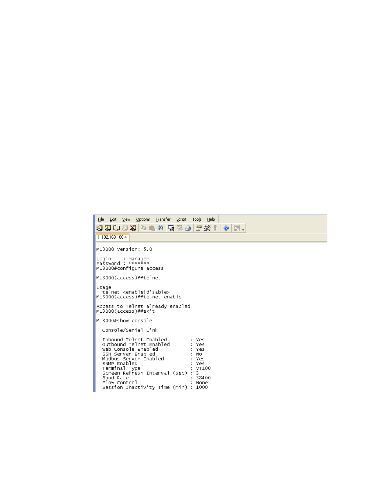
IP ADDRESSING CHAPTER 5: IP ADDRESSING
The show console command can show the status of the telnet client as well as other
console parameters. The following example reviews the console parameters with the
console
command. Note that telnet is enabled.
ML3000# show console
Console/Serial Link
Inbound Telnet Enabled: Yes
Outbound Telnet Enabled: Yes
Web Console Enabled: Yes
SNMP Enabled: Yes
Terminal Type: VT100
Screen Refresh Interval (sec): 3
Baud Rate: 38400
Flow Control: None
Session Inactivity Time (min): 10
ML3000#
show
Users can telnet to a remote host from the MultiLink family of switches using the following
syntax.
telnet <ipaddress> [port=<port number>]
The default port for telnet is 23.
To start a telnet session through the EnerVista Secure Web Management software,
Select the Administration > Telnet menu item.
The default port for telnet is 23.
5–6 MULTILINK ML3000 ETHERNET COMMUNICATIONS SWITCH – INSTRUCTION MANUAL
Page 81

CHAPTER 5: IP ADDRESSING IP ADDRESSING
NOTE
The ML3000 will time out an idle telnet session. It may be useful to see who is currently
connected to the switch. It may also be useful for a person to remotely terminate a telnet
session. To facilitate this, the ML3000 supports the following two commands:
show session
kill session id=<session>
For example:
ML3000# user
ML3000(user)## useraccess user=peter service=telnet enable
Telnet Access Enabled.
ML3000(user)## exit
ML3000# show session
Current Sessions:
SL# Sessn Id Connection User Name User Mode
1 1 163.10.10.14 manager Manager
2 2 163.11.11.1 peter Manager
3 3 163.12.12.16 operator Operator
ML3000# kill session id=3
Session Terminated
ML3000#
In the above example, the user with username “peter” is given telnet access. Then multiple
users telnet into the switch. This is shown using the
operator session is then terminated using the
show session command. The user
kill session command.
Note
A maximum of four simultaneous telnet sessions are allowed at any time on the switch.
The commands in these telnet windows are executed in a round robin fashion; that is, if
one window takes a long time to finish a command, the other windows may encounter a
delay before the command is completed. For example, if one window is executing a file
download, the other windows will not be able to execute the command before the file
transfer is completed. As well, if a outbound telnet session is started from the switch
(through a telnet window) then other windows will not be able to execute a command until
the telnet session is completed.
MULTILINK ML3000 ETHERNET COMMUNICATIONS SWITCH – INSTRUCTION MANUAL 5–7
Page 82

IP ADDRESSING CHAPTER 5: IP ADDRESSING
5.3 Setting Parameters
5.3.1 Setting Serial Port Parameters
To be compliant with IT or other policies the console parameters can be changed from the
CLI interface. This is best done by setting the IP address and then telnet over to the switch.
Once connected using telnet, the serial parameters can be changed. If you are using the
serial port, remember to set the VT-100 emulation software properties to match the new
settings.
The serial port parameters are modified using the
following syntax:
set serial [baud=<rate>] [data=<5|6|7|8>] [parity=<none|odd|even>] [stop=<1|1.5|2>]
[flowctrl=<none|xonxoff>]
Where <rate> = standard supported baud rates.
set serial command with the
Note
5.3.2 System Parameters
Changing these parameters through the serial port will cause loss of connectivity. The
terminal software parameters (e.g. HyperTerminal) will also have to be changed to
match the new settings.
To see the current settings of the serial port, use the
show serial command to query the
serial port settings as illustrated below.
ML3000# show serial
Baud Rate: 38400
Data: 8
Parity: No Parity
Stop: 1
Flow Control: None
The system parameters can be queried and changed. To query the system parameters,
two commands are frequently used:
show sysconfig and show setup. Usage for both
commands is illustrated below.
The following example lists system parameters using the
show setup command. Most
parameters here cannot be changed.
ML3000# show setup
Version: ML3000 build 1.6.1 Apr 29 2005 11:10:13
MAC Address: 00:20:06:27:0a:e0
IP Address: 3.94.247.41
Subnet Mask: 255.255.252.0
Gateway Address: 3.94.244.1
CLI Mode: Manager
System Name: ML3000
System Description: 25 Port Modular
Ethernet Switch
System Contact: multilin.tech@ge.com
System Location: Markham, Ontario
System ObjectId: 1.3.6.1.4.1.13248.12.7
ML3000#
5–8 MULTILINK ML3000 ETHERNET COMMUNICATIONS SWITCH – INSTRUCTION MANUAL
Page 83

CHAPTER 5: IP ADDRESSING IP ADDRESSING
The following example lists system parameters using the show sysconfig command.
Most parameters here can be changed.
ML3000# show sysconfig
System Name: ML3000
System Contact: multilin.tech@ge.com
System Location: Markham, Ontario
Boot Mode: manual
Inactivity Timeout(min): 120
Address Age Interval(min): 300
Inbound Telnet Enabled: Yes
Web Agent Enabled: Yes
Time Zone: GMT-05hours:00minutes
Day Light Time Rule: Canada
System UpTime: 7 Days 12 Hours 30 Mins 46
Secs
ML3000#
System variables can be changed. Below is a list of system variables which GE
recommends changing.
•
System Name: Using a unique name helps you to identify individual devices in a
network.
System Contact and System Information: This is helpful for identifying the
•
administrator responsible for the switch and for identifying the locations of
individual switches.
To set these variables, change the mode to be SNMP configuration mode from the
manager mode using the following syntax
snmp
setvar [sysname|syscontact|syslocation] =<string>
The following command sequence sets the system name, system location and system
contact information.
ML3000# snmp
ML3000(snmp)## setvar ?
setvar: Configures system name, contact or
location
Usage: setvar
[sysname|syscontact|syslocation]=<string>
ML3000(snmp)## setvar syslocation=Fremont
System variable(s) set successfully
ML3000(snmp)## exit
ML3000#
MULTILINK ML3000 ETHERNET COMMUNICATIONS SWITCH – INSTRUCTION MANUAL 5–9
Page 84

IP ADDRESSING CHAPTER 5: IP ADDRESSING
5.3.3 Date and Time
It may be necessary to set the day, time or the time zone manually. This can be done by
using the
syntax:
To set the time to be 08:10 am in the -5 hours from GMT (Eastern Standard Time) and to set
the date as 11 May 2005, the following sequence of commands are used.
The syntax for other date and time commands are:
The following command sequence sets the daylight location:
The date and time can only be set through the command line interface software.
set command with the necessary date and time options with the following
set timezone GMT=[+ or -] hour=<0-14>
min=<0-59>
set date year=<2001-2035> month=<1-12> day=<1-31>
[format=<mmddyyyy|ddmmyyyy|yyyymmdd>]
set time hour=<0-23> min=<0-59> sec=<0-59> [zone=GMT[+/-]hh:mm]
ML3000# set time hour=8 min=10 sec=0 zone=GMT-5:00
Success in setting device time
ML3000# show time
Time: 8:10:04
ML3000# show timezone
Timezone: GMT-05hours:00minutes
ML3000# set date year=2005 month=5 day=11
Success in setting device date
ML3000# show date
System Date: Wednesday 15-11-2005 (in mm
-dd-yyyy format)
ML3000#
set timeformat format=<12|24>
set daylight country=<country name>
ML3000# set daylight country=Canada
Success in setting daylight savings to the
given location/country Canada
ML3000# show daylight
Daylight savings location name: Canada
ML3000#
5.3.4 Network Time
Many networks synchronize the time using a network time server. The network time server
provides time to the different machines using the Simple Network Time Protocol (SNTP). To
specify the SNTP server, one has to
1. Set the IP parameters on the switch
2. Define the SNTP parameters
5–10 MULTILINK ML3000 ETHERNET COMMUNICATIONS SWITCH – INSTRUCTION MANUAL
Page 85
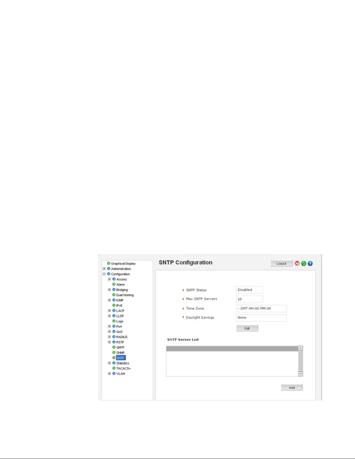
CHAPTER 5: IP ADDRESSING IP ADDRESSING
To set the SNTP parameter with the command line software, enter the SNTP configuration
mode from the manager. The
setsntp, sync, and sntp commands can then be used to
setup the time synchronization automatically from the SNTP server. Note it is not sufficient
to setup the SNTP variables. Make sure to setup the synchronization frequency as well as
enable SNTP. The syntax for the above commands is shown below.
setsntp server = <ipaddress> timeout = <1-10>
retry = <1-3>
sync [hour=<0-24>] [min=<0-59>] (default = 24
hours)
sntp [enable|disable]
To set the SNTP server to be 3.94.210.5 (with a time out of 3 seconds and a number of
retries set to 3 times); allowing the synchronization to be ever 5 hours, the following
sequence of commands are used
ML3000# sntp
ML3000(sntp)## setsntp server=3.94.210.5 timeout=3 retry=3
SNTP server is added to SNTP server
database
ML3000(sntp)## sync hour=5
ML3000(sntp)## sntp enable
SNTP is already enabled.
ML3000(sntp)## exit
ML3000(sntp)#
SNTP parameters can be configured through the EnerVista Secure Web Management
software with the Configuration > SNTP menu item. The SNTP menu allows the time zone
(hours from GMT) to be defined along with other appropriate parameters on setting the
time and synchronizing clocks on network devices.
MULTILINK ML3000 ETHERNET COMMUNICATIONS SWITCH – INSTRUCTION MANUAL 5–11
Page 86

IP ADDRESSING CHAPTER 5: IP ADDRESSING
NOTE
The edit button allows editing of the SNTP parameters as shown below. Adding or deleting
SNTP servers is accomplished by using the add and delete buttons. Clicking the edit button
allows the specific SNTP parameter settings to be modified.
After the proper SNTP values are entered, click OK to register the changes, or click Cancel
to back out from the changes made.
To add an SNTP server, click the add button on the Configuration > SNTP menu. The menu
prompts you to add IP address of an SNTP server, the time out in seconds and the number
of retries, before the time synchronization effort is aborted. The Sync Now button allows
synchronization as soon as the server information is added.
Note
If your site has internet access, there are several SNTP servers available online. A quick
search will yield information about these servers. You can use the IP address of these
servers; however, please ensure the server can be reached by using the
ping command can also be launched from the EnerVista software.
The
ping command.
5–12 MULTILINK ML3000 ETHERNET COMMUNICATIONS SWITCH – INSTRUCTION MANUAL
Page 87

CHAPTER 5: IP ADDRESSING IP ADDRESSING
The Time Out value is in seconds. Note the time server can be a NTP server available on
the Internet. Ensure the IP parameters are configured for the switch and the device can be
pinged by the switch. Once the server is added, it is listed with the other SNTP servers.
MULTILINK ML3000 ETHERNET COMMUNICATIONS SWITCH – INSTRUCTION MANUAL 5–13
Page 88

IP ADDRESSING CHAPTER 5: IP ADDRESSING
5.4 System Configuration
5.4.1 Saving and Loading – Command Line
Note
Place the Switch offline while transferring Setting Files to the Switch.
When transferring Settings Files from one Switch to another, the IP address of the
originating Switch will also be transferred. The user must therefore reset the IP address
on the receiving Switch before connecting to the network.
Configuration changes are automatically registered but not saved; that is, the effect of the
change is immediate. However, if power fails, the changes are not restored unless they
saved using the
save command. It is also a good practice to save the configuration on
another network server using the tftp or ftp protocols. Once the configuration is saved, it
can be loaded to restore the settings. At this time, the saved configuration parameters are
not in a human readable format. The commands for saving and loading configurations on
the network are:
saveconf mode=<serial|tftp|ftp>
<ipaddress> file=<name>
loadconf mode=<serial|tftp|ftp>
<ipaddress> file=<name>
Ensure the machine specified by the IP address has the necessary services running. For
serial connections, x-modem or other alternative methods can be used. In most situations,
the filename must be a unique, since overwriting files is not permitted by most ftp and tftp
servers (or services). Only alphanumeric characters are allowed in the filename.
The following example illustrated how to save the configuration on a tftp server
ML3000# saveconf mode=tftp 3.94.240.9 file=ML3000set
Do you wish to upload the configuration?
['Y' or 'N'] Y
The saveconf and loadconf commands are often used to update software. Before the
software is updated, it is advised to save the configurations. The re-loading of the
configuration is not usually necessary; however, in certain situations it maybe needed and
it is advised to save configurations before a software update. The
loadconf command
requires a reboot for the new configuration to be active. Without a reboot the older
configuration is used by the MultiLink family of switches.
saveconf and loadconf commands are often used to update software to the
The
ML3000. These commands will be deprecated in the version 2.x and above, and replaced
with the
instead of
ftp, tftp, or xmodem commands. It is advised to begin using these commands
saveconf and loadconf.
5.4.2 Config file
Multilink ML3000 Firmware can use the ftp or tftp (or xmodem if using the CLI) to upload
and download information to a server running the proper services. One useful capability
provided is export of the CLI commands used to configure the switch. To do this, use
Config Upload/Download.
Using Config Download, examination of the contents of the saved file would appear as
shown below:
5–14 MULTILINK ML3000 ETHERNET COMMUNICATIONS SWITCH – INSTRUCTION MANUAL
Page 89

CHAPTER 5: IP ADDRESSING IP ADDRESSING
<ML3000 -conf-1.0>
################################################################
# Copyright (c) 2001-2005 GE Multilin, Inc All rights reserved.
# RESTRICTED RIGHTS
# ---------------------------------
# Use, duplication or disclosure is subject to U.S. Government
# restrictions as set forth in Sub-division (b)(3)(ii) of the
# rights in Technical Data and Computer Software clause at
# 52.227-7013.
#
# This file is provided as a sample template to create a backup
# of GE MultiLink switches. As such, this script
# provides insights into the configuration of GE MultiLink
# switches settings. GE Multilin, Inc. recommends that modifications of this
# file and the commands should be verified by the User in a
# test environment prior to use in a "live" production network.
# All modifications are made at the User's own risk and are
# subject to the limitations of the GE MultiLink software End User
# License Agreement (EULA). Incorrect usage may result in
# network shutdown. GE Multilin, Inc. is not liable for incidental or
# consequential damages due to improper use.
################################################################
***This is a Machine Generated File.
***Only the SYSTEM config block is editable.
***Editing any other block will result in error while loading.
##########################################################
# Hardware Configuration - This area shows the type of #
# hardware and modules installed. #
##########################################################
[HARDWARE]
MULTILINK ML3000 ETHERNET COMMUNICATIONS SWITCH – INSTRUCTION MANUAL 5–15
Page 90

IP ADDRESSING CHAPTER 5: IP ADDRESSING
[SYSTEM]
***Edit below this line only***
system_name=ML3000
system_contact=support@gemultilin.com
system_location= Markham, Ontario
boot_mode=manual
system_ip=192.168.5.5
system_subnet=0.0.0.0
system_gateway=0.0.0.0
idle_timeout=10
telnet_access=enable
snmp_access=enable
web_access=enable
***Edit above this line only***
##########################################################
# User Accounts - This area configures user accounts for #
# accessing this system. #
##########################################################
...
FIGURE 5–1: Contents of a config file
Note
1. A config file allows only certain portions of the file to be edited by a user. Changing
any other part of the file will result in the system not allowing the file to be loaded,
as the CRC computed and stored in the file would not be matched. Should you
want to edit, edit the System portion of the file only. GE Multilin, Inc. recommends
editing the “script” file (see below)
2. File names cannot have special characters such as *#!@$^&* space and control
characters.
5–16 MULTILINK ML3000 ETHERNET COMMUNICATIONS SWITCH – INSTRUCTION MANUAL
Page 91

CHAPTER 5: IP ADDRESSING IP ADDRESSING
ML3000# show config
[HARDWARE]
type= ML3000
slotB=8 Port TP Module
##########################################################
5.4.3 Displaying configuration
Using SWM, the need to display specific CLI commands for configuring capabilities is not
needed. The menus are modular and are alphabetically sorted to display each necessary
component in a logical manner. This section is repeated from the CLI manual, should the
need arise to view the necessary commands. The best way to view these commands is to
telnet to the switch using the Telnet menu from the Administration menu.
To display the configuration or to view specific modules configured, the ‘show config’
command is used as described below.
Syntax show config [module=<module-name>]
Where module-name can be:
Name Areas affected
system
event Event Log and Alarm settings
port Port settings, Broadcast Protection and QoS settings
bridge Age time setting
stp STP, RSTP and LLL settings
ps Port Security settings
mirror Port Mirror settings
sntp SNTP settings
llan VLAN settings
gvrp GVRP settings
snmp SNMP settings
web Web and SSL/TLS settings
tacacs TACACS+ settings
auth 802.1x Settings
igmp IGMP Settings
smtp SMTP settings
IP Configuration, Boot mode, Users settings (e.g. login
names, passwords)
If the module name is not specified the whole configuration is displayed.
MULTILINK ML3000 ETHERNET COMMUNICATIONS SWITCH – INSTRUCTION MANUAL 5–17
Page 92

IP ADDRESSING CHAPTER 5: IP ADDRESSING
# System Manager - This area configures System related #
# information. #
##########################################################
[SYSTEM]
***Edit below this line only****
system_name=Main
system_contact=someone@joe.com
system_location= Markham, Ontario
boot_mode=manual
system_ip=192.168.1.15
system_subnet=0.0.0.0
system_gateway=192.168.1.11
idle_timeout=10
telnet_access=enable
snmp_access=enable
web_access=enable
--more—
...
FIGURE 5–2: ’show config’ command output
5–18 MULTILINK ML3000 ETHERNET COMMUNICATIONS SWITCH – INSTRUCTION MANUAL
Page 93

CHAPTER 5: IP ADDRESSING IP ADDRESSING
ML3000# show config module=snmp
[HARDWARE]
type= ML3000
slotB=8 Port TP Module
##########################################################
# Network Management - This area configures the SNMPv3 #
# agent. #
##########################################################
[SNMP]
engineid=LE_v3Engine
defreadcomm=public
defwritecomm=private
deftrapcomm=public
authtrap=disable
com2sec_count=0
group_count=0
view_count=1
view1_name=all
view1_type=included
view1_subtree=.1
view1_mask=ff
--more—
...
FIGURE 5–3: Displaying specific modules using the ‘show config’ command
MULTILINK ML3000 ETHERNET COMMUNICATIONS SWITCH – INSTRUCTION MANUAL 5–19
Page 94

IP ADDRESSING CHAPTER 5: IP ADDRESSING
ML3000# show config module=snmp,system
[HARDWARE]
type= ML3000
slotB=8 Port TP Module
##########################################################
# System Manager - This area configures System related #
# information. #
##########################################################
[SYSTEM]
***Edit below this line only****
system_name=Main
system_contact=someone@joe.com
system_location= Markham, Ontario
boot_mode=manual
system_ip=192.168.1.15
system_subnet=0.0.0.0
system_gateway=192.168.1.11
idle_timeout=10
telnet_access=enable
snmp_access=enable
web_access=enable
--more—
...
FIGURE 5–4: Displaying configuration for different modules.
Note – multiple modules can be specified on the command line
5.4.4 Saving Configuration
It is advisable to save the configuration before updating the software, as it may be
necessary in certain situations. The
new configuration. Without a reboot, the ML3000 used the previous configuration. When
reboot is selected, the user is prompted as follows:
Select “Y”. The ML3000 will prompt:
Select “N”.
loadconf command requires a reboot to activate the
Reboot? ['Y' or 'N']
Save Current Configuration?
5–20 MULTILINK ML3000 ETHERNET COMMUNICATIONS SWITCH – INSTRUCTION MANUAL
Page 95

CHAPTER 5: IP ADDRESSING IP ADDRESSING
Additional capabilities have been added to save and load configurations. The commands
are:
ftp <get|put|list|del> type=<app|config|oldconf|script|hosts|log> host=<hostname>
ip=<ipaddress> file=<filename> user=<user> pass=<password>
tftp <get|put> type=<app|config|oldconf|script|hosts|log> host=<hostname>
ip=<ipaddress> file=<filename>
xmodem <get|put> type=<app|config|oldconf|script|hosts|log>
The arguments are describe below:
type: Specifies whether a log file or host file is uploaded or downloaded. This can also
perform the task of exporting a configuration file or uploading a new image to
the switch
host, ip, file, user, pass: These parameters are associated with ftp/tftp server
communications.
The user can save the configuration in old (v2 format) and new (v3 format). The v3 format
must be used to utilize the ASCII and CLI Script capability.
save [format=v2|v3]
Note
With release 1.7 and higher, the configuration can be saved in the older format (binary
object) or in a new format as an ASCII file. The new format is recommended by GE
Multilin. Use the old format only if there are multiple MultiLink switches on the network
running different versions of software. GE Multilin recommends upgrading all switches
to the most current software release.
To ease the process of uploading and executing a series of commands, the ML3000 can
create a host (equivalent to creating a host table on many systems). The command for
creating a host is:
host <add|edit|del> name=<host-name> ip=<ipaddress> user=<user>
pass=<password>
show host command displays the host table entries
The
ML3000# access
ML3000(access)## host add name=server ip=192.168.5.2
Host added successfully
ML3000(access)## show host
No Host Name IP Address User Password
=========================================
1 server 192.168.5.2 -- ******
2-- -- -- -3-- -- -- -4-- -- -- -5-- -- -- -6-- -- -- -7-- -- -- -8-- -- -- -9-- -- -- -10 -- -- -- --
ML3000(access)##
MULTILINK ML3000 ETHERNET COMMUNICATIONS SWITCH – INSTRUCTION MANUAL 5–21
Page 96

IP ADDRESSING CHAPTER 5: IP ADDRESSING
###############################################################
#
# Copyright (c) 2001-2005 GE Multilin, Inc All rights reserved.
# RESTRICTED RIGHTS
# ---------------------------------
# Use, duplication or disclosure is subject to U.S. Government
# restrictions as set forth in Sub-division (b)(3)(ii) of the
# rights in Technical Data and Computer Software clause at
# 52.227-7013.
#
# This file is provided as a sample template to create a backup
# of GE MultiLink switches configurations. As such,
# this script provides insights into the configuration of GE MultiLink switch's settings.
# GE Multilin, Inc. recommends that modifications of this
# file and the commands should be verified by the User in a
# test environment prior to use in a "live" production network.
# All modifications are made at the User's own risk and are
# subject to the limitations of the GE MultiLink Firmware End User
# License Agreement (EULA). Incorrect usage may result in
# network shutdown. GE Multilin, Inc. is not liable for incidental or
# consequential damages due to improper use.
###############################################################
#
##########################################################
# System Manager - This area configures System related #
# information. #
##########################################################
set bootmode type=manual
ipconfig ip=192.168.5.5 mask=0.0.0.0 dgw=0.0.0.0
set timeout=10
access
telnet enable
snmp enable
web=enable
exit
##########################################################
# User Accounts - This area configures user accounts for #
# accessing this system. #
##########################################################
user
add user=manager level=2
passwd user=manager
manager
<additional lines deleted for succinct viewing>
5.4.5 Script File
Script file is a file containing a set of CLI commands which are used to configure the
switch. CLI commands are repeated in the file for clarity, providing guidance to the user
editing the file as to what commands can be used for modifying variables used by
Firmware. The script file does not have a check sum at the end and is used for configuring
a large number of switches easily. As with any configuration file that is uploaded, GE
Multilin, Inc. recommends that modifications of this file and the commands should be
verified by the user in a test environment prior to use in a "live" production network.
The script file will look familiar to people familiar with the CLI commands as all the
commands saved in the script file are described in the CLI User Guide. A sample of the
script file is shown below.
5–22 MULTILINK ML3000 ETHERNET COMMUNICATIONS SWITCH – INSTRUCTION MANUAL
Page 97
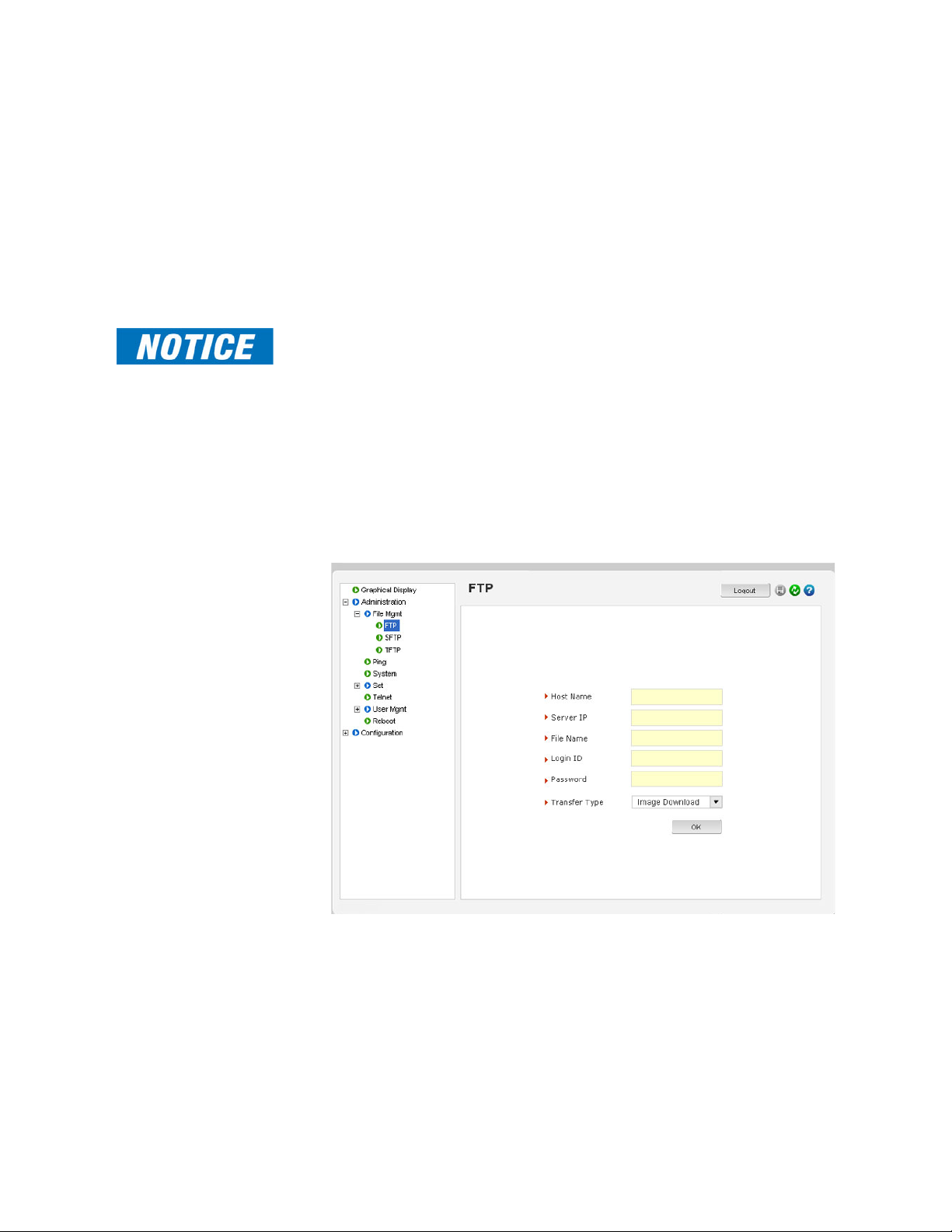
CHAPTER 5: IP ADDRESSING IP ADDRESSING
In the above example, note that all the commands are CLI commands. This script provides
an insight into the configuration of GE MultiLink switches settings. GE Multilin, Inc.
recommends that modifications of this file and the commands should be verified by the
User in a test environment prior to use in a "live" production network
To ease the process of uploading the script files, use the Script Upload/Download
capability described above.
5.4.6 Saving and Loading – EnerVista Software
Note
Place the Switch offline while transferring Setting Files to the Switch.
When transferring Settings Files from one Switch to another, the IP address of the
originating Switch will also be transferred. The user must therefore reset the IP address
on the receiving Switch before connecting to the network.
After configuration changes are made, all the changes are automatically saved. It is a
good practice to save the configuration on another server on the network using the
ftp protocols. Once the configuration is saved, the saved configuration can be reloaded
or
tftp
to restore the settings. At this time, the saved or loaded configuration parameters are not
in a human readable format.
The following figure illustrates the FTP window, which can be used to save the
configuration, as well as up load new images or reload a saved configuration.
Ensure the machine specified by the IP address has the necessary services running on it.
For serial connections, x-modem or other alternative methods can be used. Generally, the
filename name must be a unique filename, as over-writing files is not permitted by most
FTP and TFTP servers (or services).
The following figure illustrates saving the configuration on a TFTP server. Note that the
menu is similar to the FTP screen described earlier.
MULTILINK ML3000 ETHERNET COMMUNICATIONS SWITCH – INSTRUCTION MANUAL 5–23
Page 98

IP ADDRESSING CHAPTER 5: IP ADDRESSING
This process can also be used to update new software to the managed MultiLink switches.
Before the software is updated, it is advised to save the configurations. Reloading of the
configuration is not usually necessary, but in certain situations it may be needed, and it is
recommended that you save configurations before a software update. Make sure to
reboot the switch after a new configuration is loaded.
The file transfer operations allowed are:
1. Image Download (or Image Upload): Copy the ML3000 image from switch to
the server (or from the server to the switch). The “Image Upload” option is
commonly used to upgrade the ML3000 image on the switch.
2. Config Download (or Config Upload): Save the configuration of the switch on
the server (or load the saved configuration from the server to the switch). This
option is used to save a backup of the ML3000 configuration or restore the
configuration (in case of a disaster.)
3. Script Download (or Script Upload): Save the necessary CLI commands used
for configuration of the switch (or upload the necessary CLI commands
needed to configure the switch). This option is used to ease the repetitive task
of configuring multiple commands or reviewing all the commands needed to
configure the ML3000.
4. Host Download (or Host Upload): Save the host information. The hosts are
created by the Configuration - Access - Host commands
5. Log Upload - Save the log file on the ftp/tftp server
To save any changes,
Click on the save ( ) icon.
The software will ask again if the changes need to be saved or
ignored.
If the changes need to be ignored, click on Cancel and reboot the
switch.
If the changes need to be saved, click on OK.
5–24 MULTILINK ML3000 ETHERNET COMMUNICATIONS SWITCH – INSTRUCTION MANUAL
Page 99
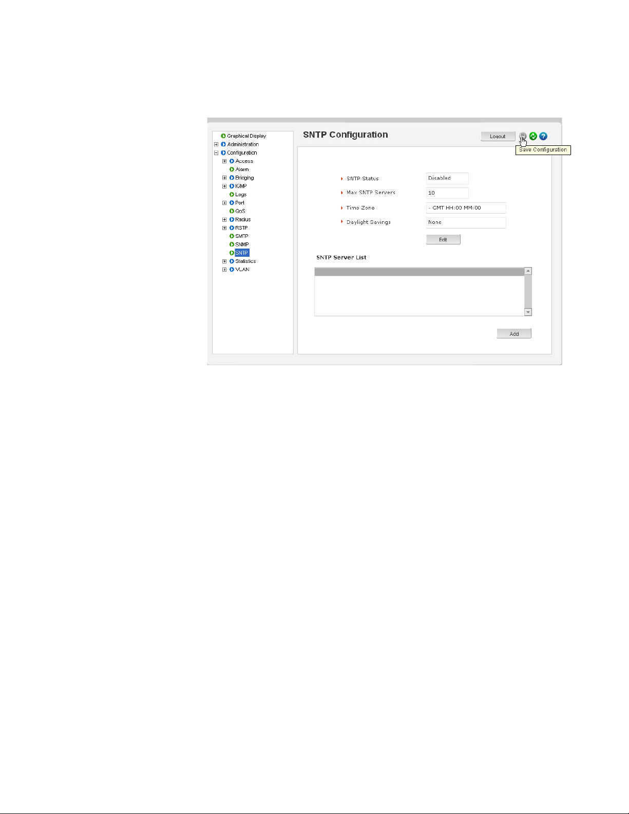
CHAPTER 5: IP ADDRESSING IP ADDRESSING
The following figures illustrate saving changes made after adding an SNTP server. This is
done by clicking on the Save icon to save current configuration
5.4.7 Host Names
Instead of typing in IP addresses of commonly reached hosts, the ML3000 allows hosts to
be created with the necessary host names, IP addresses, user names, and passwords.
Use the Configuration > Access > Host menu to create host entries
as shown below.
MULTILINK ML3000 ETHERNET COMMUNICATIONS SWITCH – INSTRUCTION MANUAL 5–25
Page 100

IP ADDRESSING CHAPTER 5: IP ADDRESSING
To add a host, click the Add button.
Fill in all the fields below to create the necessary host entries.
5–26 MULTILINK ML3000 ETHERNET COMMUNICATIONS SWITCH – INSTRUCTION MANUAL
 Loading...