

Page 1
ISO9001:2000
GE Consumer & Industrial
Multilin
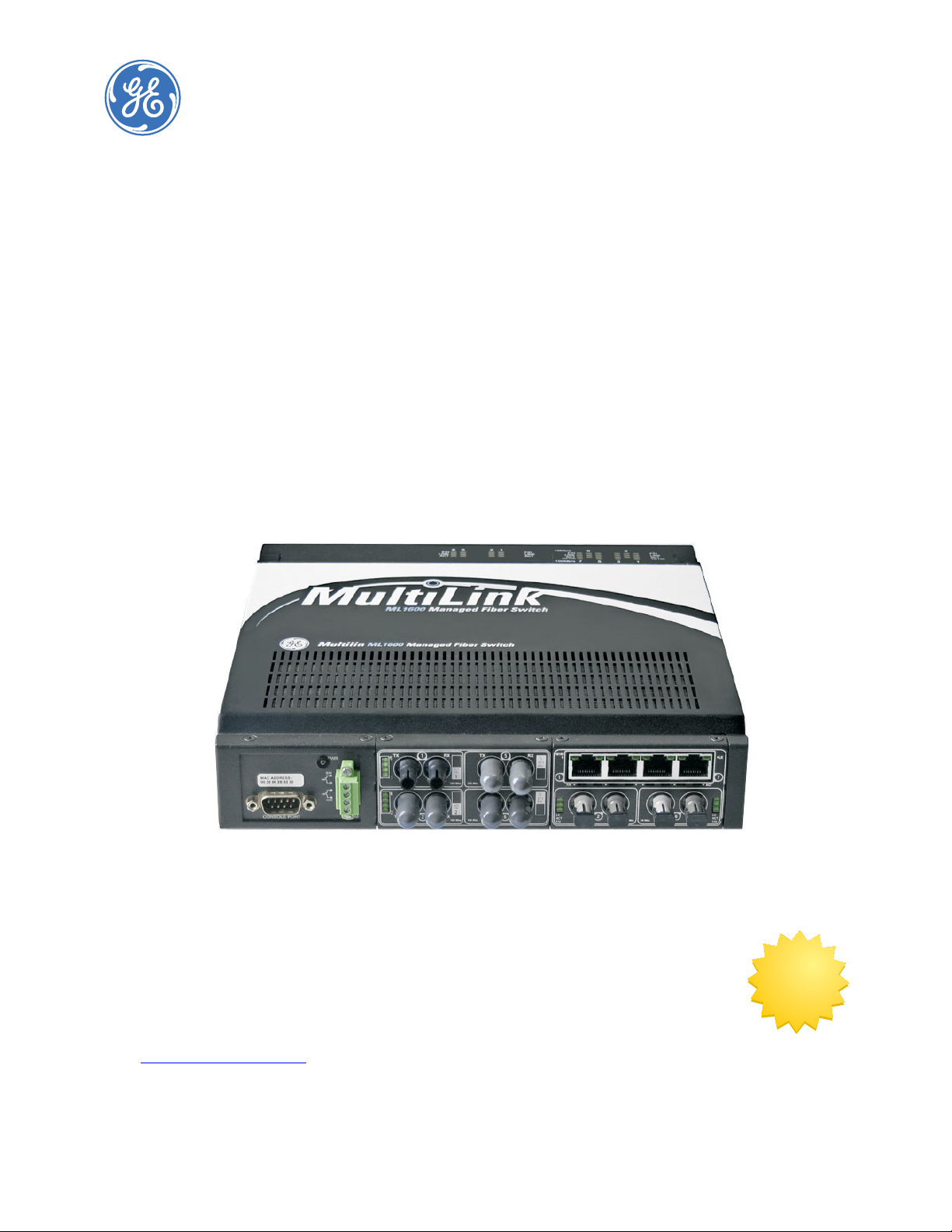
MultiLink ML1600
Ethernet Communications Switch
Instruction Manual
Software Revision 3.x
Manual P/N: 1601-0221-AA
Manual Order Code: GEK-113041J
Copyright © 2008 GE Multilin
GE Multilin
215 Anderson Avenue, Markham, Ontario
Canada L6E 1B3
Tel: (905) 294-6222 Fax: (905) 201-2098
Internet: http://www.GEmultilin.com
*1601-0221-AA*
T
E
S
I
R
E
G
D
E
R
I
G
E
GE Multilin's Quality MGMNT
System is registered to
ISO9001:2000
QMI # 005094
UL # A3775
N
I
M
L
I
U
T
L
Page 2

These instructions do not purport to cover all details or variations in equipment nor provide
for every possible contingency to be met in connection with installation, operation, or
maintenance. Should further information be desired or should particular problems arise
which are not covered sufficiently for the purchaser’s purpose, the matter should be referred
to the General Electric Company.
To the extent required the products described herein meet applicable ANSI, IEEE, and NEMA
standards; but no such assurance is given with respect to local codes and ordinances
because they vary greatly.
© 2008 GE Multilin Incorporated. All rights reserved.
GE Multilin Multilink ML1600 instruction manual for revision 3.x.
Multilink ML1600 is a registered trademark of GE Multilin Inc.
The contents of this manual are the property of GE Multilin Inc. This documentation is
furnished on license and may not be reproduced in whole or in part without the permission
of GE Multilin. The content of this manual is for informational use only and is subject to
change without notice.
Part numbers contained in this manual are subject to change without notice, and should
therefore be verified by GE Multilin before ordering.
Part number: 1601-0221-AA (June 2008)
Page 3

TOC TABLE OF CONTENTS
Table of Contents
1: INTRODUCTION GETTING STARTED ............................................................................................................. 1-1
I
NSPECTING THE PACKAGE AND PRODUCT ........................................................................1-1
ORDERING ........................................................................................................................... 1-2
O
RDER CODES .......................................................................................................................1-2
SPECIFICATIONS .................................................................................................................1-3
T
ECHNICAL SPECIFICATIONS ................................................................................................ 1-3
E
NVIRONMENTAL SPECIFICATIONS ......................................................................................1-5
P
HYSICAL SPECIFICATIONS ...................................................................................................1-5
A
PPROVALS AND WARRANTY ..............................................................................................1-5
SOFTWARE OVERVIEW ..................................................................................................... 1-6
C
OMMAND LINE SOFTWARE ................................................................................................1-6
E
NERVISTA SOFTWARE .........................................................................................................1-6
B
EFORE STARTING .................................................................................................................1-7
COMMAND LINE INTERFACE SOFTWARE ..................................................................... 1-8
C
ONSOLE CONNECTION ....................................................................................................... 1-8
C
ONSOLE SETUP .................................................................................................................... 1-8
C
ONSOLE SCREEN ................................................................................................................. 1-9
L
OGGING IN FOR THE FIRST TIME ....................................................................................... 1-9
A
UTOMATIC IP ADDRESS CONFIGURATION .......................................................................1-9
S
ETTING THE IP PARAMETERS ............................................................................................. 1-10
P
RIVILEGE LEVELS ..................................................................................................................1-12
U
SER MGMNT ...................................................................................................................... 1-12
H
ELP ........................................................................................................................................1-13
E
XITING ................................................................................................................................... 1-15
ENERVISTA SECURE WEB MGMNT ................................................................................. 1-16
L
OGGING IN FOR THE FIRST TIME .......................................................................................1-16
P
RIVILEGE LEVELS ..................................................................................................................1-17
U
SER MGMNT ...................................................................................................................... 1-17
M
ODIFYING THE PRIVILEGE LEVEL ......................................................................................1-20
H
ELP ........................................................................................................................................1-20
E
XITING ................................................................................................................................... 1-21
ML1600 SOFTWARE UPDATES ........................................................................................ 1-22
U
PDATING MULTILINK SOFTWARE .....................................................................................1-22
S
ELECTING THE PROPER VERSION ......................................................................................1-22
U
PDATING THROUGH THE COMMAND LINE .......................................................................1-22
U
PDATING THROUGH THE ENERVISTA SOFTWARE ...........................................................1-23
2: PRODUCT
DESCRIPTION
OVERVIEW ............................................................................................................................ 2-1
NTRODUCTION TO THE ML1600 ....................................................................................... 2-1
I
D
ESIGN ASPECTS ...................................................................................................................2-2
COMMUNICATIONS MODULES ....................................................................................... 2-3
F
OUR-PORT MODULES ......................................................................................................... 2-3
S
IX-PORT MODULES ..............................................................................................................2-4
E
IGHT-PORT MODULES .........................................................................................................2-4
G
IGABIT (1000 MBPS) MODULES ......................................................................................2-5
FEATURES AND BENEFITS ................................................................................................ 2-6
P
ACKET PRIORITIZATION, 802.1P QOS ............................................................................. 2-6
F
RAME BUFFERING AND FLOW CONTROL .........................................................................2-6
M
ULTILINK SWITCH SOFTWARE ..........................................................................................2-6
MULTILINK ML1600 ETHERNET COMMUNICATIONS SWITCH – INSTRUCTION MANUAL TOC–I
Page 4

TABLE OF CONTENTS
ADDITIONAL FEATURES AND BENEFITS ..............................................................................2-7
APPLICATIONS .................................................................................................................... 2-8
D
ESCRIPTION ..........................................................................................................................2-8
I
NDUSTRIAL APPLICATIONS ...................................................................................................2-8
R
EDUNDANT RING TOPOLOGY ............................................................................................2-9
T
ELECOMMUNICATIONS ENVIRONMENT .............................................................................2-10
3: INSTALLATION PREPARATION ..................................................................................................................... 3-1
RECAUTIONS .........................................................................................................................3-1
P
L
OCATING THE ML1600 .....................................................................................................3-1
CONNECTING ETHERNET MEDIA ................................................................................... 3-2
D
ESCRIPTION ..........................................................................................................................3-2
C
ONNECTING ST-TYPE FIBER OPTICS (TWIST-LOCK) ........................................................ 3-2
C
ONNECTING SC-TYPE FIBER OPTICS (SNAP-IN) ..............................................................3-2
C
ONNECTING SINGLE-MODE FIBER OPTICS ......................................................................3-3
C
ONNECTING RJ45 TWISTED PAIR ....................................................................................3-3
C
ONNECTING GIGABIT MEDIA USING GBICS ....................................................................3-4
MECHANICAL INSTALLATION .......................................................................................... 3-5
DIN-
RAIL MOUNTING ...........................................................................................................3-5
M
OUNTING DIMENSIONS WITH METAL BRACKETS ........................................................... 3-6
ELECTRICAL INSTALLATION ............................................................................................ 3-8
P
OWERING THE ML1600 ....................................................................................................3-8
UL R
EQUIREMENTS FOR DC-POWERED UNITS ................................................................3-8
A
LARM CONTACTS .................................................................................................................3-9
CONNECTING A MGMNT CONSOLE TERMINAL TO THE ML1600 ........................... 3-10
D
ESCRIPTION ..........................................................................................................................3-10
4: OPERATION FUNCTIONALITY ................................................................................................................. 4-1
S
WITCHING FUNCTIONALITY ................................................................................................4-1
F
ILTERING AND FORWARDING ............................................................................................. 4-1
A
DDRESS LEARNING ..............................................................................................................4-2
S
TATUS LEDS ........................................................................................................................4-2
U
P-LINK MANUAL SWITCHES (FOR RJ45 PORT ONLY) ....................................................4-2
A
UTO-NEGOTIATION (FOR FAST ETHERNET COPPER PORTS) ............................................4-2
F
LOW CONTROL (IEEE 802.3X) .........................................................................................4-3
P
OWER BUDGET CALCULATIONS WITH FIBER MEDIA ......................................................4-4
TROUBLESHOOTING .......................................................................................................... 4-6
O
VERVIEW ..............................................................................................................................4-6
B
EFORE CALLING FOR ASSISTANCE ....................................................................................4-6
W
HEN CALLING FOR ASSISTANCE ......................................................................................4-6
5: IP ADDRESSING IP ADDRESS AND SYSTEM INFORMATION ................................................................... 5-1
O
VERVIEW ..............................................................................................................................5-1
IMPORTANCE OF AN IP ADDRESS .................................................................................. 5-3
DHCP
AND BOOTP ...............................................................................................................5-3
B
OOTP DATABASE .................................................................................................................5-3
C
ONFIGURING DHCP/BOOTP/MANUAL/AUTO .................................................................5-3
U
SING TELNET .......................................................................................................................5-5
SETTING PARAMETERS ..................................................................................................... 5-8
S
ETTING SERIAL PORT PARAMETERS ..................................................................................5-8
S
YSTEM PARAMETERS ...........................................................................................................5-8
TOC–II MULTILINK ML1600 ETHERNET COMMUNICATIONS SWITCH – INSTRUCTION MANUAL
Page 5

TOC TABLE OF CONTENTS
DATE AND TIME .....................................................................................................................5-9
N
ETWORK TIME .....................................................................................................................5-10
SYSTEM CONFIGURATION ................................................................................................ 5-13
S
AVING AND LOADING – COMMAND LINE ........................................................................5-13
C
ONFIG FILE ........................................................................................................................... 5-13
D
ISPLAYING CONFIGURATION .............................................................................................. 5-16
S
AVING CONFIGURATION ..................................................................................................... 5-19
S
CRIPT FILE ............................................................................................................................5-21
S
AVING AND LOADING – ENERVISTA SOFTWARE ............................................................. 5-22
H
OST NAMES .........................................................................................................................5-25
E
RASING CONFIGURATION ................................................................................................... 5-26
IPV6 ........................................................................................................................................ 5-30
I
NTRODUCTION TO IPV6 .......................................................................................................5-30
W
HAT’S CHANGED IN IPV6? ............................................................................................... 5-30
IP
V6 ADDRESSING ................................................................................................................ 5-31
C
ONFIGURING IPV6 ..............................................................................................................5-32
L
IST OF COMMANDS IN THIS CHAPTER ...............................................................................5-33
6: ACCESS
CONSIDERATIONS
SECURING ACCESS ............................................................................................................ 6-1
ESCRIPTION ..........................................................................................................................6-1
D
P
ASSWORDS ...........................................................................................................................6-1
P
ORT SECURITY FEATURE .....................................................................................................6-2
CONFIGURING PORT SECURITY THROUGH THE COMMAND LINE INTERFACE .. 6-3
C
OMMANDS ............................................................................................................................6-3
S
ECURITY LOGS .....................................................................................................................6-9
A
UTHORIZED MANAGERS ..................................................................................................... 6-10
CONFIGURING PORT SECURITY WITH ENERVISTA SOFTWARE .............................. 6-12
C
OMMANDS ............................................................................................................................6-12
L
OGS .......................................................................................................................................6-14
A
UTHORIZED MANAGERS ..................................................................................................... 6-15
7: ACCESS USING RADIUS INTRODUCTION TO 802.1X .............................................................................................. 7-1
D
ESCRIPTION ..........................................................................................................................7-1
802.1
X PROTOCOL ...............................................................................................................7-1
CONFIGURING 802.1X THROUGH THE COMMAND LINE INTERFACE ................... 7-4
C
OMMANDS ............................................................................................................................7-4
E
XAMPLE ................................................................................................................................. 7-6
CONFIGURING 802.1X WITH ENERVISTA SECURE WEB MANAGEMENT
SOFTWARE ........................................................................................... 7-9
C
OMMANDS ............................................................................................................................7-9
8: ACCESS USING
TACACS+
INTRODUCTION TO TACACS+ ......................................................................................... 8-1
O
VERVIEW .............................................................................................................................. 8-1
TACACS+ F
TACACS+ P
LOW ..................................................................................................................8-2
ACKET ...............................................................................................................8-2
CONFIGURING TACACS+ THROUGH THE COMMAND LINE INTERFACE .............. 8-4
C
OMMANDS ............................................................................................................................8-4
E
XAMPLE ................................................................................................................................. 8-4
CONFIGURING TACACS+ WITH ENERVISTA SECURE WEB MANAGEMENT
SOFTWARE ........................................................................................... 8-6
MULTILINK ML1600 ETHERNET COMMUNICATIONS SWITCH – INSTRUCTION MANUAL TOC–III
Page 6

TABLE OF CONTENTS
9: PORT MIRRORING AND
SETUP
PORT MIRRORING .............................................................................................................. 9-1
D
ESCRIPTION ..........................................................................................................................9-1
PORT MIRRORING USING THE COMMAND LINE INTERFACE .................................. 9-2
C
OMMANDS ............................................................................................................................9-2
PORT SETUP ......................................................................................................................... 9-3
C
OMMANDS ............................................................................................................................9-3
F
LOW CONTROL ....................................................................................................................9-5
B
ACK PRESSURE ....................................................................................................................9-5
B
ROADCAST STORMS ............................................................................................................9-8
L
INK LOSS ALERT ..................................................................................................................9-11
PORT MIRRORING USING ENERVISTA SECURE WEB MANAGEMENT
SOFTWARE ........................................................................................... 9-13
C
OMMANDS ............................................................................................................................9-13
P
ORT SETUP ...........................................................................................................................9-14
B
ROADCAST STORMS ............................................................................................................9-16
10: VLAN VLAN DESCRIPTION ........................................................................................................... 10-1
O
VERVIEW ..............................................................................................................................10-1
T
AG VLAN VS. PORT VLAN ................................................................................................10-3
CONFIGURING PORT VLANS THROUGH THE COMMAND LINE INTERFACE ........10-4
D
ESCRIPTION ..........................................................................................................................10-4
C
OMMANDS ............................................................................................................................10-4
E
XAMPLE ................................................................................................................................. 10-5
CONFIGURING PORT VLANS WITH ENERVISTA SECURE WEB MANAGEMENT
SOFTWARE ........................................................................................... 10-9
D
ESCRIPTION ..........................................................................................................................10-9
CONFIGURING TAG VLANS THROUGH THE COMMAND LINE INTERFACE ........... 10-13
D
ESCRIPTION ..........................................................................................................................10-13
C
OMMANDS ............................................................................................................................10-13
E
XAMPLE ................................................................................................................................. 10-14
CONFIGURING TAG VLANS WITH ENERVISTA SOFTWARE ...................................... 10-20
D
ESCRIPTION ..........................................................................................................................10-20
11: VLAN REGISTRATION
OVER GARP
OVERVIEW ............................................................................................................................ 11-1
ESCRIPTION ..........................................................................................................................11-1
D
GVRP C
GVRP O
ONCEPTS ..................................................................................................................11-1
PERATIONS ..............................................................................................................11-2
CONFIGURING GVRP THROUGH THE COMMAND LINE INTERFACE ...................... 11-7
C
OMMANDS ............................................................................................................................11-7
GVRP O
PERATION NOTES ...................................................................................................11-7
CONFIGURING GVRP WITH ENERVISTA SECURE WEB MANAGEMENT
SOFTWARE ........................................................................................... 11-9
E
XAMPLE ................................................................................................................................. 11-9
12: SPANNING TREE
PROTOCOL (STP)
OVERVIEW ............................................................................................................................ 12-1
ESCRIPTION ..........................................................................................................................12-1
D
F
EATURES AND OPERATION .................................................................................................12-1
CONFIGURING STP ............................................................................................................ 12-3
TOC–IV MULTILINK ML1600 ETHERNET COMMUNICATIONS SWITCH – INSTRUCTION MANUAL
Page 7

TOC TABLE OF CONTENTS
13: RAPID SPANNING
TREE PROTOCOL
OVERVIEW ............................................................................................................................ 13-1
D
ESCRIPTION ..........................................................................................................................13-1
RSTP C
ONCEPTS ...................................................................................................................13-1
T
RANSITION FROM STP TO RSTP .......................................................................................13-2
CONFIGURING RSTP THROUGH THE COMMAND LINE INTERFACE ....................... 13-4
N
ORMAL RSTP ......................................................................................................................13-4
S
MART RSTP (RING-ONLY MODE) THROUGH THE COMMAND LINE INTERFACE .........13-14
CONFIGURING STP/RSTP WITH ENERVISTA SECURE WEB MANAGEMENT
SOFTWARE ........................................................................................... 13-16
N
ORMAL RSTP ......................................................................................................................13-16
S
MART RSTP (RING-ONLY MODE) WITH ENERVISTA SECURE WEB MANAGEMENT
S
OFTWARE .........................................................................................13-20
14: QUALITY OF SERVICE QOS OVERVIEW .................................................................................................................. 14-1
D
ESCRIPTION ..........................................................................................................................14-1
Q
OS CONCEPTS .....................................................................................................................14-1
D
IFFSERV AND QOS .............................................................................................................14-2
IP P
RECEDENCE ..................................................................................................................... 14-2
CONFIGURING QOS THROUGH THE COMMAND LINE INTERFACE ........................ 14-4
C
OMMANDS ............................................................................................................................14-4
E
XAMPLE ................................................................................................................................. 14-6
CONFIGURING QOS WITH ENERVISTA SECURE WEB MANAGEMENT
SOFTWARE ........................................................................................... 14-9
D
ESCRIPTION ..........................................................................................................................14-9
15: IGMP OVERVIEW ............................................................................................................................ 15-1
ESCRIPTION ..........................................................................................................................15-1
D
IGMP C
ONCEPTS ..................................................................................................................15-1
IP M
ULTICAST FILTERS .........................................................................................................15-4
R
ESERVED ADDRESSES EXCLUDED FROM IP MULTICAST (IGMP) FILTERING ...............15-5
IGMP S
UPPORT ..................................................................................................................... 15-5
CONFIGURING IGMP THROUGH THE COMMAND LINE INTERFACE ...................... 15-6
C
OMMANDS ............................................................................................................................15-6
E
XAMPLE ................................................................................................................................. 15-8
CONFIGURING IGMP WITH ENERVISTA SECURE WEB MANAGEMENT
SOFTWARE ........................................................................................... 15-11
E
XAMPLE ................................................................................................................................. 15-11
16: SNMP OVERVIEW ............................................................................................................................ 16-1
ESCRIPTION ..........................................................................................................................16-1
D
SNMP C
T
S
ONCEPTS .................................................................................................................16-1
RAPS ......................................................................................................................................16-3
TANDARDS ............................................................................................................................16-3
CONFIGURING SNMP THROUGH THE COMMAND LINE INTERFACE ..................... 16-5
C
OMMANDS ............................................................................................................................16-5
E
XAMPLE ................................................................................................................................. 16-6
CONFIGURING SNMP WITH ENERVISTA SECURE WEB MANAGEMENT
SOFTWARE ........................................................................................... 16-11
E
XAMPLE ................................................................................................................................. 16-11
CONFIGURING RMON ....................................................................................................... 16-14
MULTILINK ML1600 ETHERNET COMMUNICATIONS SWITCH – INSTRUCTION MANUAL TOC–V
Page 8

TABLE OF CONTENTS
DESCRIPTION ..........................................................................................................................16-14
C
OMMANDS ............................................................................................................................16-14
17: MISCELLANEOUS
COMMANDS
ALARM RELAYS ...................................................................................................................17-1
ESCRIPTION ..........................................................................................................................17-1
D
C
ONFIGURING ALARM RELAYS THROUGH THE COMMAND LINE INTERFACE ................17-2
C
ONFIGURING ALARM RELAYS WITH ENERVISTA SECURE WEB MANAGEMENT
S
OFTWARE .........................................................................................17-5
E-MAIL ................................................................................................................................... 17-6
D
ESCRIPTION ..........................................................................................................................17-6
C
OMMANDS ............................................................................................................................17-6
E
XAMPLE ................................................................................................................................. 17-8
STATISTICS ........................................................................................................................... 17-9
V
IEWING PORT STATISTICS WITH ENERVISTA SECURE WEB MANAGEMENT
S
OFTWARE .........................................................................................17-9
SERIAL CONNECTIVITY ...................................................................................................... 17-11
D
ESCRIPTION ..........................................................................................................................17-11
HISTORY ................................................................................................................................ 17-12
C
OMMANDS ............................................................................................................................17-12
PING ...................................................................................................................................... 17-13
P
ING THROUGH THE COMMAND LINE INTERFACE ............................................................17-13
P
ING THROUGH ENERVISTA SECURE WEB MANAGEMENT SOFTWARE .........................17-13
PROMPT ................................................................................................................................ 17-14
C
HANGING THE COMMAND LINE PROMPT ........................................................................17-14
SYSTEM EVENTS .................................................................................................................. 17-15
D
ESCRIPTION ..........................................................................................................................17-15
C
OMMAND LINE INTERFACE EXAMPLE ............................................................................... 17-15
E
NERVISTA EXAMPLE ............................................................................................................17-16
S
UBSYSTEM EVENT LIST .......................................................................................................17-17
COMMAND REFERENCE .................................................................................................... 17-21
M
AIN COMMANDS .................................................................................................................17-21
C
ONFIGURATION COMMANDS .............................................................................................17-23
18: MODBUS PROTOCOL MODBUS CONFIGURATION ............................................................................................. 18-1
VERVIEW ..............................................................................................................................18-1
O
C
OMMAND LINE INTERFACE SETTINGS ............................................................................... 18-1
E
NERVISTA SETTINGS ............................................................................................................18-2
MEMORY MAPPING ............................................................................................................ 18-3
M
ODBUS MEMORY MAP .......................................................................................................18-3
F
ORMAT CODES .....................................................................................................................18-24
19: APPENDIX REVISION HISTORY ............................................................................................................ 19-1
R
ELEASE DATES .....................................................................................................................19-1
C
HANGES TO THE MANUAL ..................................................................................................19-2
CONFORMANCE STATEMENTS ....................................................................................... 19-5
FCC RFI S
C
ANADIAN EMISSION STATEMENT ......................................................................................19-5
TATEMENT ...........................................................................................................19-5
WARRANTY .......................................................................................................................... 19-6
TOC–VI MULTILINK ML1600 ETHERNET COMMUNICATIONS SWITCH – INSTRUCTION MANUAL
Page 9

GE Consumer & Industrial
Multilin
1.1 Getting Started
Multilink ML1600
Ethernet Communications Switch
Chapter 1: Introduction
Introduction
1.1.1 Inspecting the Package and Product
Examine the shipping container for obvious damage prior to installing this product; notify
the carrier of any damage that you believe occurred during shipment or delivery. Inspect
the contents of this package for any signs of damage and ensure that the items listed
below are included.
This package should contain:
• MultiLink ML1600 Ethernet Switch, base unit (configured with user-selected port
module options installed)
• Set of two vertical mount brackets with mounting screws
• Installation and user guide (this manual)
Remove the items from the shipping container. Be sure to keep the shipping container
should you need to re-ship the unit at a later date. To validate the product warranty, please
complete and return the enclosed product registration card to GE Multilin as soon as
possible.
In the event there are items missing or damaged, contact the party from whom you
purchased the product. If the unit needs to be returned, please use the original shipping
container if possible. Refer to Troubleshooting on page 4–7, for specific return procedures.
MULTILINK ML1600 ETHERNET COMMUNICATIONS SWITCH – INSTRUCTION MANUAL 1–1
Page 10

ORDERING CHAPTER 1: INTRODUCTION
1.2 Ordering
1.2.1 Order Codes
The following table illustrates the order codes for the MultiLink ML1600 Ethernet Switch.
Table 1–1: ML1600 order code
ML1600 – * – * – * - – Base Unit
A
Module |
Power supply AC
HI
LO
Modules A1A1|4 × 10 Mb ST mm fiber
A2 A2 | 4 × 100 Mb ST mm fiber
A3 A3 | 4 × 100 Mb SC mm fiber
A4 A4 | 8 × 10/100 Mb RJ45 copper
A5 A5 | 2 × 10 Mb ST mm fiber + 4 × 10/100 Mb RJ45 copper
A6 A6 | 2 × 100 Mb ST mm fiber + 4 × 10/100 Mb RJ45 copper
A7 A7 | 2 × 100 Mb SC mm fiber + 4 × 10/100 Mb RJ45 copper
A8 A8 | 2 × 100 Mb SC sm fiber + 4 × 10/100 Mb RJ45copper
AA AA | 4 × 100 Mb LC mm fiber + 4 × 10/100 Mb RJ45 copper
AB AB | 8 × 100 Mb LC mm fiber
AC AC | 4 × 100 Mb LC sm fiber + 4 × 10/100 Mb RJ45 copper
AD AD | 8 × 100 Mb LC sm fiber
AE AE | 2 × 100 Mb LC sm fiber + 6 × 10/100 Mb RJ45 copper
AF AF | 2 × 10 Mb ST mm fiber and 2 × 100 Mb ST mm fiber
AH AH | 8 × 100 Mb MTRJ mm fiber
AJ AJ | 4 × 100 Mb MTRJ mm f iber + 4 × 10/100 Mb RJ45 copper
AK AK | 2 × 100 Mb MTRJ mm fiber + 6 × 10/100 Mb RJ45 copper
G3 G3 | 1 × 1000 Mb SC mm fiber 2km + 2 × 100 Mb SC mm fiber
G4 G4 | 1 × 1000 Mb SC mm fiber 2km + 4 × RJ45 10/100 Mb RJ45 copper
G5 G5 | 2 × 1000 Mb SC mm fiber 2km
GC GC | 2 × 100 Mb SC mm fiber + 1 × 1000 Mb RJ45 copper
GD GD | 1 × 1000 Mb RJ45 copper and 4 × 10/100 Mb RJ45 copper
GE GE | 2 × 1000 Mb RJ45 copper
GF GF | 1 × 1000 Mb SC sm fiber 10km + 2 × 100 Mb SC mm fiber
GH GH | 1 × 1000 Mb SC sm fiber 10km + 4 × 10/100 Mb RJ45 copper
GJ GJ | 2 × 1000 Mb SC sm fiber 10km
GK GK | 1 x 1000 Mb SC sm fiber 25km + 2 x 100 Mb SC mm fiber
GL GL | 1 x 1000 Mb SC sm fiber 25km
GM GM | 2 x 1000 Mb SC sm fiber 25km
GN GN | 1 x 1000 Mb SC sm fiber 40km + 2 x 100 Mb SC mm fiber
GO GO | 1 x 1000 Mb SC sm fiber 40km + 4 x 10/100 Mb RJ45 copper
GP GP | 2 x 1000 Mb SC sm f iber 40km
GQ GQ | 1 x 1000 Mb SC sm fiber 70km + 2 x 100 Mb SC mm fiber
GR GR | 1 x 1000 Mb SC sm fiber 70km + 4 x 10/100 Mb RJ45 copper
GS GS | 2 x 1000 Mb SC sm fiber 70km
Harsh Environment X Standard Environment
B MultiLink ML1600 Ethernet Switch
|
| | 100 to 240 V AC Power Supply
|
| | 110 to 250 V DC / 100 to 240 V AC Power Supply
|
| | 36 to 60 V DC Power Supply
H Harsh Chemical Environment Option
1–2 MULTILINK ML1600 ETHERNET COMMUNICATIONS SWITCH – INSTRUCTION MANUAL
Page 11

CHAPTER 1: INTRODUCTION SPECIFICATIONS
1.3 Specifications
1.3.1 Technical Specifications
PERFORMANCE
Ethernet (10 Mb):.............................................14880 pps
Fast Ethernet (100 Mb):................................148,800 pps
Gigabit Ethernet (1000 Mb): ......................1488000 pps
Switching processing:..................................Store and forward with IEEE 802.3x full-duplex flow -
control, non-blocking
Data rate:...........................................................10 Mbps, 100 Mbps and 1000 Mbps
Address table capacity:...............................4K node, self-learning with address aging
Packet buffer size:..........................................240 KB for 10/100; 120 KB for 1000 Mb
Latency: ..............................................................5 μs + packet time (100 to 100Mbps)
15 μs + packet time (10 to 10 Mbps and 10 to 100 Mbps)
RO mode recovery time (typical):............≤5 ms/hop
NETWORK STANDARDS AND COMPLIANCE
Ethernet V1.0/V2.0 IEEE 802.3: ................10Base-T
IEEE 802.3u:.......................................................100Base-TX, 100Base-FX
IEEE 802.3z: .......................................................1000Base-X Ethernet (auto-negotiation)
IEEE 802.3ab:....................................................1000Base-X Ethernet
IEEE 802.1p:.......................................................Priority protocol
IEEE 802.1d:.......................................................Spanning tree protocol
IEEE 802.1q:.......................................................VLAN tagging
IEEE 802.3x:.......................................................Flow control
MAXIMUM 10 MBPS ETHERNET SEGMENT LENGTHS
Unshielded twisted pair: .............................100 m (328 ft.)
Shielded twisted pair:...................................150 m (492 ft.)
10Base-FL multi-mode fiber optic: .......2 km (6562 ft .)
10Base-FL single-mode fiber optic: .....10 km (32810 ft.)
MAXIMUM STANDARD FAST ETHERNET SEGMENT LENGTHS
10Base-T (CAT 3, 4, 5 UTP): ........................100 m (328 ft.)
100Base-TX (CAT 5 UTP): .............................100 m (328 ft.)
Shielded twisted pair:...................................150 m (492 ft.)
100Base-FX, half-duplex, multi-mode: 412 m (1350 ft.)
100Base-FX, full-duplex, multi-mode: .2.0 km (6562 ft.)
100Base-FX, half-duplex, single-mode: 412 m (1350 ft .)
100Base-FX, full-duplex, long reach: ...40.0 km (122K ft.)
MAXIMUM STANDARD GIGABIT ETHERNET SEGMENT LENGTHS
1000Base-T (CAT5e or higher is recommended): 100 m (328 ft.)
1000Base-SX, full-duplex, multi-mode (62.5 μm cable): 220 m
1000Base-SX, full-duplex, multi-mode (50 μm cable): 550 m
FIBER MULTI-MODE CONNECTORS
Fiber port, ST (twist-lock): ..........................fiber multi-mode, 10 Mb 10Base-FL
Fiber port, SC-type (snap-in): ...................fiber multi-mode, 100Base-FX
Fiber port, ST-type (twist-lock): ...............fiber multi-mode, 100Base-FX
Fiber port, 1000Base-FX:............................GBIC modules
MULTILINK ML1600 ETHERNET COMMUNICATIONS SWITCH – INSTRUCTION MANUAL 1–3
Page 12

SPECIFICATIONS CHAPTER 1: INTRODUCTION
FIBER SINGLE-MODE CONNECTORS
Fiber port, SC-type:........................................Fiber optic single-mode, 100Base-FX
Fiber port, 1000Base-FX:............................GBIC modules
LEDS
LK:..........................................................................steady ON when media link is operational
ACT:.......................................................................ON with receiver port activity
FDX/HDX:............................................................ON = full-duplex mode
OFF = half-duplex mode
100/10: ................................................................ON = 100 Mbps; OFF = 10 Mbps
ALARM RELAY CONTACTS
One NC indicating internal power, one NC software controllable
Maximum Voltage:.........................................up to 250 V AC, 220 V DC
Maximum Switching Power:......................60 W, 125 VA
Maximum Carrying Current:......................2 A @ 30 V DC
0.2 A @ 220 V DC
MGMNT CONSOLE
Connector:.........................................................DB-9 for RS-232 “null-modem” cable (sometimes called
an X-modem cable)
POWER SUPPLY
Input voltage: ...................................................LOW RANGE (LO Power Supply)
Nominal DC Voltage: 48 V DC
Min/Max DC Voltage: 36/60 V DC
................................................................................HIGH RANGE (HI and AC Power Supply)
Nominal DC Voltage: 110 to 250 V DC
Min/Max DC Voltage: 88/300 V DC
Nominal AC Voltage: 100 to 240 V AC
Min/Max AC Voltage: 85/265 V AC
Input current (fiber): ......................................LO: 1.59 A maximum
HI: 1.8 A maximum for AC voltage
0.9 A maximum for DC voltage
AC: 1.8 A maximum
Standard terminal block: ...........................“–”, “+”, internally floating
Ground: ...............................................................Terminal for filter ground wire, external connection to the
ML1600 chassis
Power consumption:.....................................55 watts typical; 60 watts maximum for a fully loaded
fiber model; 35 watts maximum for a fully-loaded RJ45
model
Internal Fuse:.......................................... HI: Ceramic, axial SLO BLO, 3 A /350 V AC
Manufacturer: Conquer
Part Number: SCD-A 003
LO: Ceramic, axial SLO BLO, 5 A /350 V AC
Manufacturer: Conquer
Part Number: SCD-A 005
PER-PORT JUMPERS AND SWITCHES
The copper daughter board has on internal switch for selecting MDI-MDIX crossover on port # 1.
Other port-specific user settings (such as FDX or HDX, copper 10/100 speed) can be fixed using
software commands.
1–4 MULTILINK ML1600 ETHERNET COMMUNICATIONS SWITCH – INSTRUCTION MANUAL
Page 13

CHAPTER 1: INTRODUCTION SPECIFICATIONS
1.3.2 Environmental Specifications
OPERATING ENVIRONMENT
Ambient temperature: .................................–40 to 185°F (–40 to 85°C) for IEC 60068-2-1, IEC 60068-
2-2
Nominal ≤ 50°C
Storage temperature:...................................–60 to 210°F (–50 to 100°C)
Ambient relative humidity: ........................5% to 95% (non-condensing)
Altitude:...............................................................2000 m
1.3.3 Physical Specifications
MOUNTING
Vertical:...............................................................suitable for stand-alone or rack mounting
PACKAGING
Enclosure: .........................................................rugged high-strength sheet metal
Dimensions: ......................................................1.94 in. × 9.25 in. × 10.24 in. (H × W × D)
4.92 cm × 23.5 cm × 26.0 cm (H × W × D)
1.3.4 Approvals and Warranty
APPROVALS
FCC:.......................................................................Emissions meet FCC part 15 class A
NEBS:....................................................................level 3
ETSI: ......................................................................certified for carrier central offices
IEEE: ......................................................................IEEE P1613 environmental standard for electric power
IEC:.........................................................................IEC61850 EMC and operating conditions class C for
CE:..........................................................................EN 50082-1, EN 55022:1998, EN 60950 3rd Edition
UL:..........................................................................UL Listed/Recognized (file E156407)
CSA:.......................................................................Certified per C22.2 No.60950-1 1
WARRANTY
24 months from date of shipment
Manufactured in USA
GE Multilin reserves the right to change specifications, performance, characteristics, and/or model
offerings without notice.
substations
power substations
UL 60950-1 1
st
edition
st
edition
MULTILINK ML1600 ETHERNET COMMUNICATIONS SWITCH – INSTRUCTION MANUAL 1–5
Page 14

SOFTWARE OVERVIEW CHAPTER 1: INTRODUCTION
1.4 Software Overview
1.4.1 Command Line Software
Commands typed by the user will be shown in the following color and font.
command
The MultiLink Switch Software prompt will be shown in bold and fixed-width text , with a #
or
> character at the end. The default prompt is indicated as follows:
ML1600#
The following hold for syntax rules:
• Syntax rules are italicized
• The command part is in bold
• Optional entries are shown in [square brackets]
• Parameter values within are shown in <pointed brackets>
• Optional parameter values are shown again in [square brackets]
Thus, the syntax
command [parameter1=<value1>[,paramter2=<value2>]]
parameter3=<value3|value4>
indicates the following:
• parameters 1 and 2 are optional
• parameter 2 can be used optionally only if parameter 1 is specified
• parameter 3 is mandatory.
Whenever the word PC is used, it implies a UNIX, Linux, Windows, or any other operating
system based workstation, computer, personal computer, laptop, notebook or any other
computing device. Most of the manual uses Windows XP based examples. While effort has
been made to indicate other operating system interactions, it is best to use a Windows-XP
based machine when in doubt.
The documentation reflects features of MultiLink Switch Software version 1.6.1 or later. If
your switch is not at the current version, GE Multilin recommends upgrade to version 1.6.1
or later. Please refer to the GE Multilin website for information on upgrading the MultiLink
Switch Software.
1.4.2 EnerVista Software
Icons common to the EnerVista MultiLink Secure Web MGMNT (SWM) software for edit,
delete, save and refresh are:
• Edit - edit the values
• Delete - delete the current row or the value(s)
• Save - save configuration changes
• Refresh - repaint the screen
1–6 MULTILINK ML1600 ETHERNET COMMUNICATIONS SWITCH – INSTRUCTION MANUAL
Page 15

CHAPTER 1: INTRODUCTION SOFTWARE OVERVIEW
1.4.3 Before Starting
This section explains how to setup the GE MultiLink family of switches using the console
port on the switch. Some of the functionality includes setting up the IP address of the
switch, securing the switch with a user name and password, setting up VLANs and more.
Before you start, it is recommended to acquire the hardware listed below and be ready
with the items listed.
For initial configuration through the serial/console port:
1. A female-female null modem cable.
2. A serial port. If your PC does not have a serial port, you may want to invest in
a USB-to-serial converter or USB-to-serial cable.
3. Terminal emulation software such as HyperTerminal or other equivalent
software. Ensure the software supports Xmodem protocol, as you may need
this in the future to update the MultiLink Switch Software.
4. Enough disk space to store and retrieve the configuration files as well as copy
software files. We recommend at least 15 MB of disk space for this purpose.
5. For access security - decide on a manager level account name and password
6. IP address, netmask, default gateway for the switch being configured.
As a default, the switch has no IP (Internet Protocol) address and subnet mask. For first
time use, the IP address has to be assigned. This can only be done by using the console
interface provided.
The same procedure can also be used for other configuration changes or updates (for
example, changing the IP address, VLAN assignments and more). Once the IP address is
assigned and a PC is networked to the switch, the switch's command line interface (CLI)
can be accessed via telnet. To manage the switch through in-band (networked) access
(e.g. telnet, or web browser Interface), you should configure the switch with an IP address
and subnet mask compatible with your network. Also, change the manager password to
control access privileges from the console.
Many other features such as optimizing the switch's performance, traffic engineering and
traffic prioritizing, VLAN configuration, and improving network security can be configured
through the switch's console interface as well as in-band (networked) access, once the IP
address is setup. Besides the IP address, setting up the SNMP parameters allows
configuration and monitoring through an SNMP network MGMNT station running a
network MGMNT program.
MULTILINK ML1600 ETHERNET COMMUNICATIONS SWITCH – INSTRUCTION MANUAL 1–7
Page 16
COMMAND LINE INTERFACE SOFTWARE CHAPTER 1: INTRODUCTION
1.5 Command Line Interface Software
1.5.1 Console Connection
The connection to the console is accessed through the DB-9 RS232 connector on the
switch marked as the console port . This command line interface (or CLI) provides access to
the switch commands. It can be accessed by attaching a VT100 compatible terminal or a
PC running terminal emulation software to the console port.
USB-to-serial adapters are also available for computers that do not native serial ports but
have access to USB ports.
The interface through the console or the console MGMNT interface (or CMI) enables you to
reconfigure the switch and to monitor switch status and performance.
Once the switch is configured with an IP address, the command line interface (or CLI) is
also accessible using telnet as well as the serial port. Access to the switch can be either
through the console interface or remotely over the network. Simultaneous access (that is,
through the console port as well as through the network) to the MultiLink switch is not
permitted.
The Command Line Interface (CLI) enables local or remote unit installation and
maintenance. The MultiLink family of switches provides a set of system commands which
allow effective monitoring, configuration and debugging of the devices on the network.
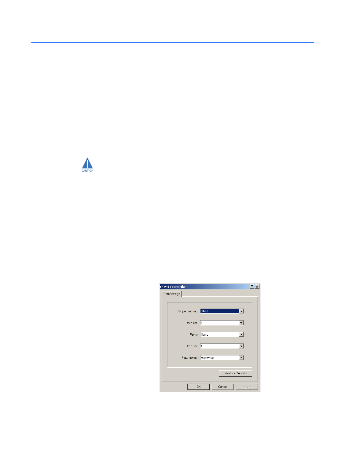
1.5.2 Console Setup
Connect the console port on the switch to the serial port on the computer using the serial
cable listed above. The settings for the HyperTerminal software emulating a VT100 are
shown below. Make sure the serial parameters are set as shown (or bps = 38400, data bits
= 8, parity = none, stop bits = 1, flow control = none).
FIGURE 1–1: Serial Settings in HyperTerminal
1–8 MULTILINK ML1600 ETHERNET COMMUNICATIONS SWITCH – INSTRUCTION MANUAL
Page 17

CHAPTER 1: INTRODUCTION COMMAND LINE INTERFACE SOFTWARE
1.5.3 Console Screen
Once the console cable is connected to the PC and the software configured, ML1600 legal
disclaimers and other text scrolls by on the screen.
The line interface prompt appears displaying the switch model number (e.g. ML1600>)
The switch has three modes of operation: operator (least privilege), manager, and
configuration. The prompts for the switches change as the switch changes modes from
operator to manager to configuration. The prompts are shown below with a brief
description.
• ML1600>
Operator Level - for running operations queries
• ML1600#
Manager Level - for setting and reviewing commands
• ML1600##
Configuration Level - for changing the switch parameter values
For additional information on default users, user levels and more, refer to User MGMNT on
page 1–12.
1.5.4 Logging in for the First Time
For the first time, use the default user name and passwords assigned by GE. They are:
•Username: manager
Password: manager
•Username: operator
Password: operator
We recommend you login as manager for the first time to set up the IP address as well as
change user passwords or create new users.
1.5.5 Automatic IP Address Configuration
The ML1600 is operational immediately after it is powered up. The advanced MGMNT and
configuration capabilities of the ML1600 allows you to easily configure, manage, and
secure your devices and network.
Before starting, ensure you have the following items:
• RJ45 Ethernet cable
•PC with an Ethernet port
• Microsoft Internet Explorer 6.0 or higher
• Macromedia Flash Player 5.0 or higher (available from http://
www.macromedia.com/shockwave/download/
download.cgi?P1_Prod_Version=ShockwaveFlash)
Ensure both software components are installed before proceeding.
The ML1600 can search the network for commonly used services that can issue an IP
address. If the switch is connected to a network, the ML1600 uses the following process to
find an IP address.
MULTILINK ML1600 ETHERNET COMMUNICATIONS SWITCH – INSTRUCTION MANUAL 1–9
Page 18

COMMAND LINE INTERFACE SOFTWARE CHAPTER 1: INTRODUCTION
Note
If the ML1600 is not connected to a network, then proceed to Step 3 below. or use the
default IP address.
Step 1:
The ML1600 will scan the network for a DHCP server. If the server responds, the ML1600
will acquire and set the assigned IP address. To manage the switch, determine the
assigned IP address and enter as follows in Internet Explorer:
https://
<assigned_IP_address>
Ensure that https is entered, not http, and that there is connectivity (that is, you can ping
the switch).
Step 2:
If there is no response from a DCHP server, the ML1600 will query for a BOOTP server. If the
server responds, the ML1600 will acquire and set the assigned IP address. To manage the
switch, determine the assigned IP address and enter as follows in Internet Explorer:
https://
<assigned_IP_address>
Ensure that https is entered, not http, and that there is connectivity (that is, you can ping
the switch).
Step 3:
If there is no response from either a DCHP or BOOTP server, or if the switch is not
connected to a network, the switch will assign itself an IP address. The ML1600 will check
to see if IP address 192.168.1.2, with a network mask of 255.255.255.0, is free. If so, it will
assume these values. If this IP address is assigned to another device, the ML1600 will
repeat steps 1 through 3 to find a DCHP or BOOTP server or wait for the 192.168.1.2
address to become free.
Once connected, the browser will display a login prompt. The default login is:
•Username: manager
Password: manager
1.5.6 Setting the IP Parameters
To setup the switch, the IP address and other relevant TCP/IP parameters have to be
specified.
The IP address on the MultiLink switch is set to 192.168.1.2 from the factory. The switch is
fully operational as a Layer 2 switch as a default. Setting a default IP address can
potentially cause duplicate IP address problem if multiple switches are powered on and
installed on the network. To manage the switch, an IP address has to be programmed.
Before starting, please ensure that the IP address assigned to the switch is known or
contact your system/network administrator to get the IP address information. Follow the
steps listed below to configure the switch.
Z Ensure the power is off.
Z Follow the steps described above for connecting the console cable
and setting the console software.
Z Power on the switch.
1–10 MULTILINK ML1600 ETHERNET COMMUNICATIONS SWITCH – INSTRUCTION MANUAL
Page 19

CHAPTER 1: INTRODUCTION COMMAND LINE INTERFACE SOFTWARE
Z Once the login prompt appears, login as manager using default
password (manager).
Z Configure the IP address, network mask and default gateway as
per the IP addressing scheme for your network.
Z Set the manager password (this step is recommended; refer to the
following section).
Z Save the settings (without saving, the changes made will be lost).
Z Power off the switch (or a software reboot as discussed below).
Z Power on the switch - login with the new login name and password
Z From the PC (or from the switch) ping the IP address specified for
the switch to ensure connectivity
Z From the switch ping the default gateway specified (ensure you are
connected to the network to check for connectivity) to ensure
network connectivity
Syntax:
ipconfig [ip=<ip-address>] [mask=<subnet-mask>] [dgw=<gateway>]
An example is shown below.
ML1600# ipconfig ip=3.94.247.41 mask=255.255.252.0
dgw=3.94.247.41
ML1600# save
Note
This manual assumes the reader is familiar with IP addressing schemes, net masks, and
how default gateways and routers are used in a network.
Reboot gives an opportunity to save the configuration prior to shutdown. For a reboot,
simply type in the command
reboot. Note that even though the passwords are not
changed, they can be changed later.
ML1600# reboot
Proceed on rebooting the switch? ['Y' or 'N'] Y
Do you wish to save current configuration? ['Y' or 'N'] Y
ML1600#
The ML1600 forces an answer by prompting with a “Y” or a “N” to prevent accidental
keystroke errors and loss of work.
The parameters can be viewed at any time by using the
show command. The show
command will be covered in more detail later in various sections throughout the
document.
The example below illustrates the basic setup parameters. You can use
show setup or
show sysconfig commands to view setup parameters
ML1600# show setup
Version: ML1600 build 1.6.1 Apr 29 2005 11:10:13
MAC Address: 00:20:06:27:0a:e0
IP Address: 3.94.247.41
Subnet Mask: 255.255.252.0
Gateway Address: 3.94.244.1
CLI Mode: Manager
System Name: ML1600
MULTILINK ML1600 ETHERNET COMMUNICATIONS SWITCH – INSTRUCTION MANUAL 1–11
Page 20

COMMAND LINE INTERFACE SOFTWARE CHAPTER 1: INTRODUCTION
System Description: 16 Port Modular Ethernet Switch
System Contact: multilin.tech@ge.com
System Location: Markham, Ontario
System ObjectId: 1.3.6.1.4.1.13248.12.7
ML1600# show sysconfig
System Name: ML1600
System Contact: multilin.tech@ge.com
System Location: Markham, Ontario
Boot Mode: manual
Inactivity Timeout(min): 120
Address Age Interval(min): 300
Inbound Telnet Enabled: Yes
Web Agent Enabled: Yes
Time Zone: GMT-05hours:00minutes
Day Light Time Rule: Canada
System UpTime: 0 Days 0 Hours 45 Mins 55 Secs
ML1600#
Some of the parameters in the MultiLink family of switches are shown above. The list of
parameters below indicates some of the key parameters on the switch and the
recommendations for changing them (or optionally keeping them the same).
1.5.7 Privilege Levels
Two privilege levels are available - manager and operator. Operator is at privilege level 1
and the manager is at privilege level 2 (the privilege increases with the levels). For example,
to set up a user for basic monitoring capabilities use lower number or operator level
privilege (level 1)
The Manager level provides all operator level privileges plus the ability to perform systemlevel actions and configuration commands. To select this level, enter the
name>
prompted.
For example, switching from an operator-level to manager-level, using the
command is shown below.
Note the prompt changes with the new privilege level.
Operator privileges allow views of the current configurations but do not allow changes to
the configuration. A “>” character delimits the operator-level prompt.
Manager privileges allow configuration changes. The changes can be done at the
manager prompt or for global configuration as well as specific configuration. A “#”
character delimits any manager prompt.
enable <user-
command at the Operator level prompt and enter the Manager password, when
enable <user-name>
enable
ML1600> enable manager
Password: *******
ML1600#
1.5.8 User MGMNT
A maximum of five users can be added per switch. Users can be added, deleted or
changed from a manager level account. There can be more than one manager account,
subject to the maximum number of users on the switch being restricted to five.
1–12 MULTILINK ML1600 ETHERNET COMMUNICATIONS SWITCH – INSTRUCTION MANUAL
Page 21

CHAPTER 1: INTRODUCTION COMMAND LINE INTERFACE SOFTWARE
To add a user, use the add command as shown below. The user name has to be a unique
name. The password is recommended to be at least 8 characters long with a mix of upper
case, lower case, numbers and special characters.
add user=<name> level=<number>
The following example adds a user “peter” with manager-level privilege:
ML1600# user
ML1600(user)##
Enter User Password:******
Confirm New Password:******
add user=peter level=2
ML1600(user)##
To delete a user, use the delete command as shown below.
delete user=<name>
The following example deletes the user “peter”:
ML1600(user)## delete user=peter
Confirm User Deletion(Y/N): Y
User successfully deleted
ML1600(user)##
The syntax to modify a password is shown below:
passwd user=<name>
The following example changes the password for user “peter”.
1.5.9 Help
ML1600(user)## passwd user=peter
Enter New Password:******
Confirm New Password :******
Password has been modified successfully
ML1600(user)##
The syntax to modify the privilege level for a specific user is shown below:
chlevel user=<name> level=<number>
The following example modifies the privilege level of user “peter” to Operator privileges.
ML1600(user)## chlevel user=peter level=1
Access Permission Modified
ML1600(user)##
The syntax to set the access privileges for telnet and Web services is shown below:
useraccess user=<name> service=<telnet|web> <enable|disable>
The following example sets the access privileges for telnet and Web services.
ML1600(user)## useraccess user=peter service=telnet disable
Telnet Access Disabled.
Typing the help command lists the commands you can execute at the current privilege
level. For example, typing
help at the Operator level shows the following:
ML1600> help
MULTILINK ML1600 ETHERNET COMMUNICATIONS SWITCH – INSTRUCTION MANUAL 1–13
Page 22

COMMAND LINE INTERFACE SOFTWARE CHAPTER 1: INTRODUCTION
logout ping set
terminal telnet walkmib
Contextless Commands:
! ? clear
enable exit help
show whoami
alarm
ML1600>
Help for any command that is available at the current context level can be viewed by
typing help followed by enough of the command string to identify the command. The
following syntax applies:
help <command string>
For example, to list the help for the
set time command
ML1600# help set time
set time : Sets the device Time
Usage
set time hour=<0-23> min=<0-59> sec=<0-59> [zone=GMT[+/-]hh:mm]
ML1600#
The options for a specific command can be displayed by typing the command and
pressing enter. The following syntax applies:
command <Enter>
For example, the options for the
show command are:
ML1600# show <Enter>
Usage
show active-stp
show active-snmp
show active-vlan
show address-table
show age
show alarm
show arp
show auth <config|ports>
show backpressure
show bootmode
--more--
Other ways to display help, specifically, with reference to a command or a set of
commands, use the TAB key. The following syntax applies:
<TAB>
<Command string> <TAB>
<First character of the command> <TAB>
For example, following the syntax listed above, the <TAB> key will list the available
commands in the particular privilege level:
ML1600> <TAB>
?
alarm
clear
enable
exit
help
logout
1–14 MULTILINK ML1600 ETHERNET COMMUNICATIONS SWITCH – INSTRUCTION MANUAL
Page 23

CHAPTER 1: INTRODUCTION COMMAND LINE INTERFACE SOFTWARE
ping
set
show
telnet
terminal
walkmib
whoami
ML1600>
The following example lists commands starting with a specific string
ML1600> s <TAB>
set
show
ML1600>
In the following example, the <TAB> key completes the command:
ML1600> se<TAB>
password
timeout
vlan
ML1600> set
1.5.10 Exiting
To exit from the CLI interface and terminate the console session use the logout
command. This command prompts to ensure that the logout was not mistakenly typed.
The following syntax applies:
logout
The following example illustrates logging out from a session:
ML1600> logout
Logging out from the current session [’Y’ or ’N’] Y
Connection to the host lost
MULTILINK ML1600 ETHERNET COMMUNICATIONS SWITCH – INSTRUCTION MANUAL 1–15
Page 24
ENERVISTA SECURE WEB MGMNT CHAPTER 1: INTRODUCTION
1.6 EnerVista Secure Web MGMNT
1.6.1 Logging In for the First Time
Enter the following URL in the web browser to login to the EnerVista Secure Web
Management software.
https://<IP Address assigned to the switch>
Note
Make sure you use HTTPS (secure HTTP) and not HTTP in the URL.
In the example shown in the previous section, the URL is:
https://3.94.247.41
If your site uses name services, you can use a name instead of the IP address. Please make
sure that the name is resolved to the IP address assigned to the switch.
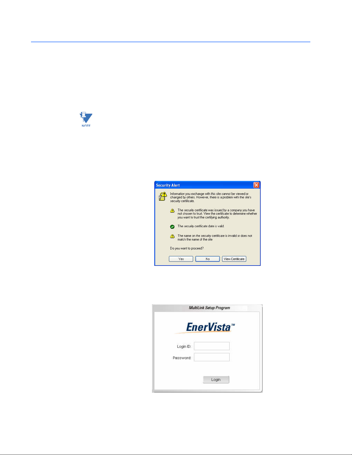
The secure site will issue the certificate check shown below.
FIGURE 1–2: Security certificate
Once you click “Yes” on the security certificate, the browser will prompt you to login.
FIGURE 1–3: Login screen
1–16 MULTILINK ML1600 ETHERNET COMMUNICATIONS SWITCH – INSTRUCTION MANUAL
Page 25
CHAPTER 1: INTRODUCTION ENERVISTA SECURE WEB MGMNT
For the first time,
Z Login with the name manager and password manager.
Z Click on Login.
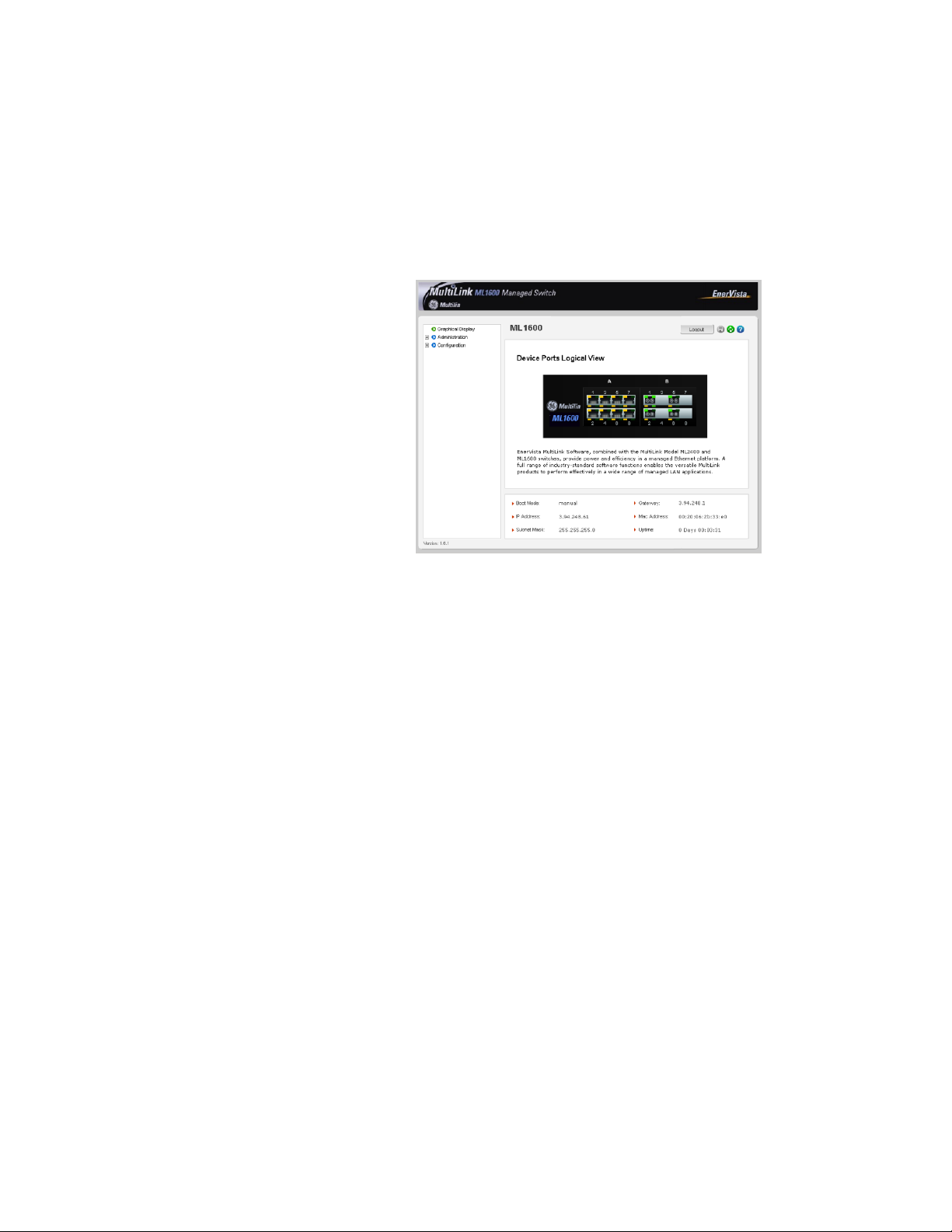
After a successful login, the welcome screen is shown. Note the different information
provided on the screen and different areas. The menus are used to configure settings on
the switch. Users can click on a specific port to open the port configuration view.
1.6.2 Privilege Levels
1.6.3 User MGMNT
A maximum of five users can be added per switch. Users can be added, deleted or
changed from a manager level account. There can be more than one manager account,
subject to the maximum number of users on the switch being restricted to five.
FIGURE 1–4: Welcome screen
• Operator privilege users: operator privileges allow views of the current
configurations but do not allow changes to the conf iguration.
• Manager privilege users: manager privileges allow configuration changes. The
changes can be done at the manager prompt or for global configuration as well as
specific configuration.
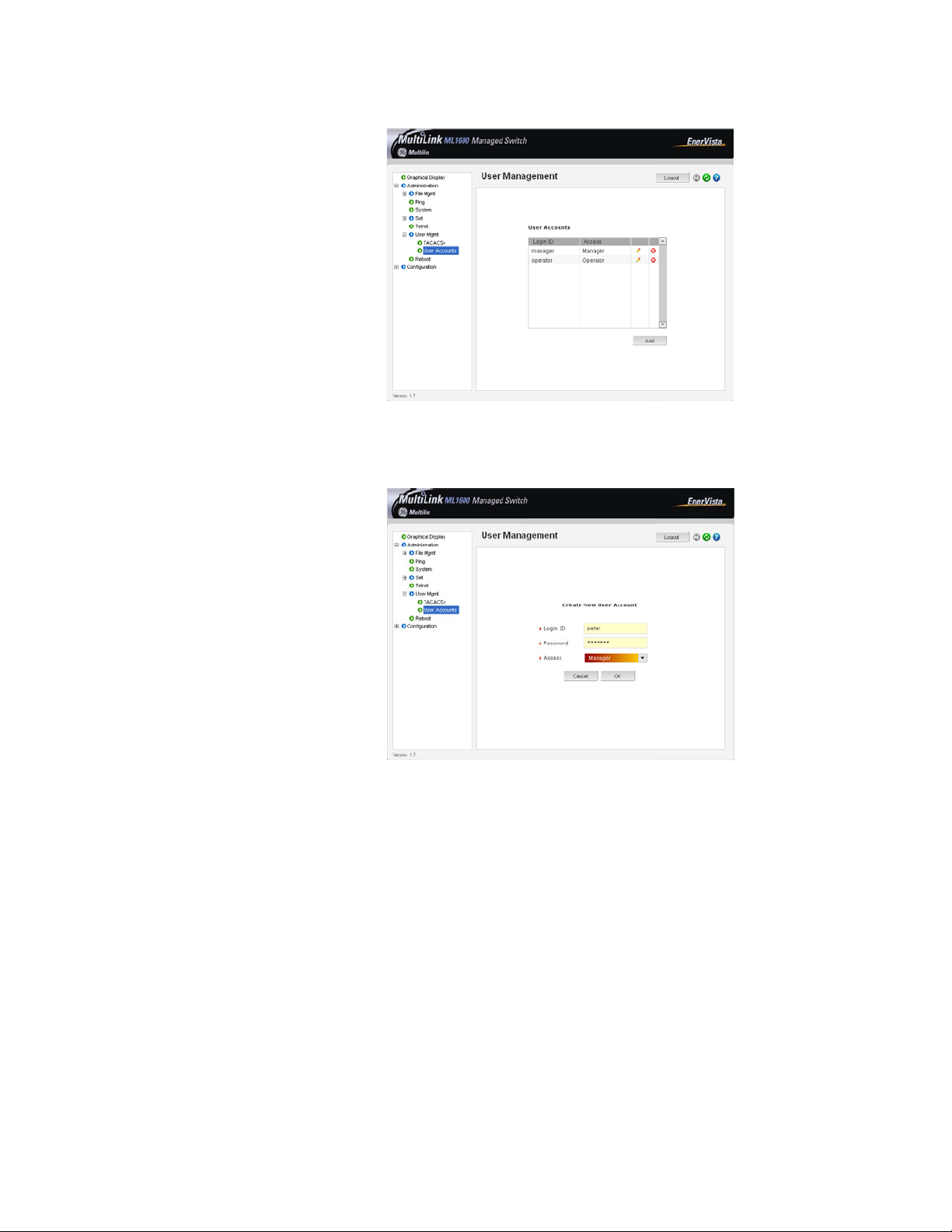
Z Select the Administration > User Mgmt > User Accounts menu
item.
Z To add a user, use the Add button.
The username must be a unique name. The password is
recommended to be at least 8 characters with a mix of upper case,
lower case, numbers and special characters
MULTILINK ML1600 ETHERNET COMMUNICATIONS SWITCH – INSTRUCTION MANUAL 1–17
Page 26
ENERVISTA SECURE WEB MGMNT CHAPTER 1: INTRODUCTION
.
In the example below, the user peter was added with manager privilege after clicking the
add button.
1–18 MULTILINK ML1600 ETHERNET COMMUNICATIONS SWITCH – INSTRUCTION MANUAL
Page 27
CHAPTER 1: INTRODUCTION ENERVISTA SECURE WEB MGMNT
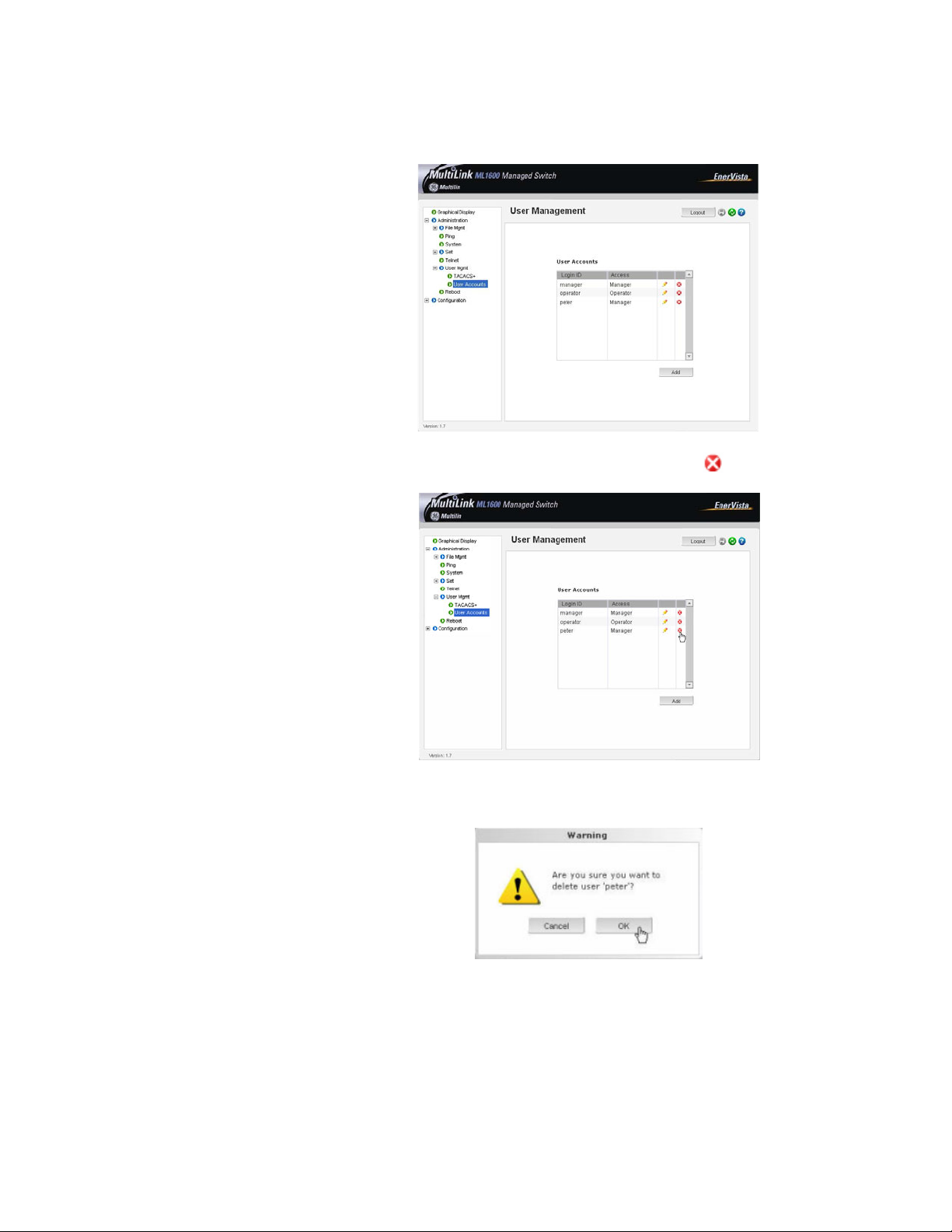
After successfully adding a user, the added user is displayed in the list of users as shown
below.
Z To delete a user, click on the delete icon ( )as shown below.
The software will prompt to verify the delete command.
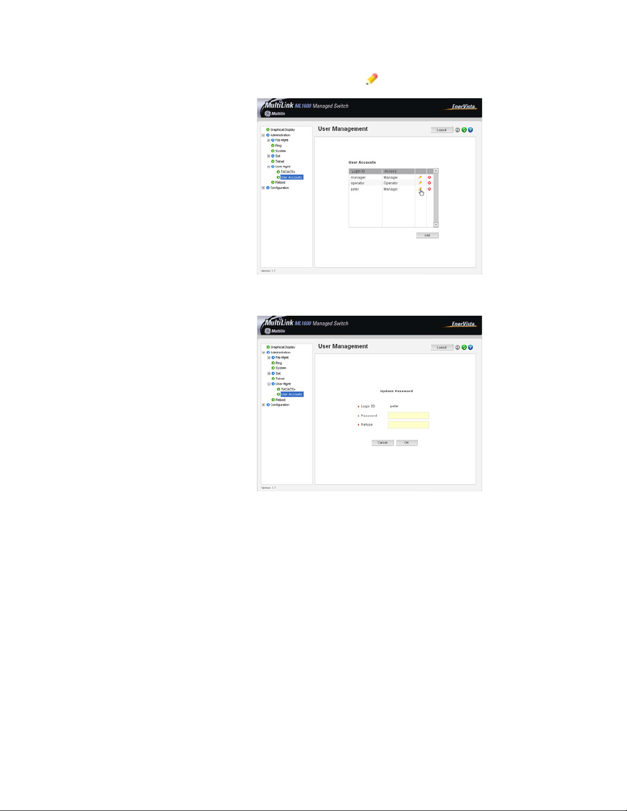
Z To modify the password, view the users as described above.
MULTILINK ML1600 ETHERNET COMMUNICATIONS SWITCH – INSTRUCTION MANUAL 1–19
Page 28
ENERVISTA SECURE WEB MGMNT CHAPTER 1: INTRODUCTION
Z Click on the edit icon ( ).
After clicking on the edit icon, the screen opens up for modifying the password.
In this example, the user ID peter was selected for modification. The password for peter
will be modified after the new password is entered.
1.6.4 Modifying the Privilege Level
Privilege levels cannot be changed from the EnerVista Secure Web MGMNT (SWM)
software. This can only be done through the CLI interface or alternately by deleting the
user and adding the same user with the proper privilege level.
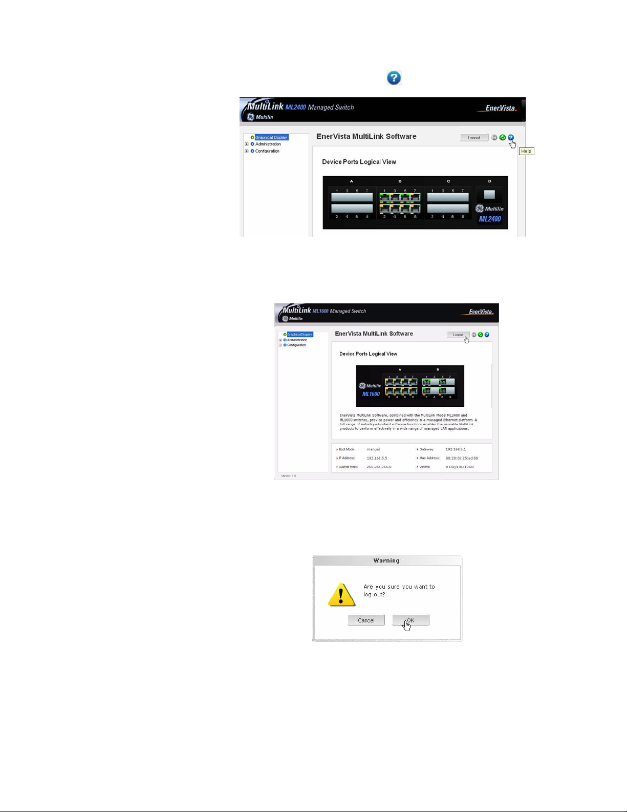
1.6.5 Help
Help for the EnerVista Secure Web Management software can be obtained as follows:
1–20 MULTILINK ML1600 ETHERNET COMMUNICATIONS SWITCH – INSTRUCTION MANUAL
Page 29
CHAPTER 1: INTRODUCTION ENERVISTA SECURE WEB MGMNT
Z Click on the Help icon ( ) as shown below:
1.6.6 Exiting
Z To exit or logout, click on the logout button.
To confirm the logout:
Z Select OK in the pop-up window.
MULTILINK ML1600 ETHERNET COMMUNICATIONS SWITCH – INSTRUCTION MANUAL 1–21
Page 30

ML1600 SOFTWARE UPDATES CHAPTER 1: INTRODUCTION
1.7 ML1600 software updates
1.7.1 Updating MultiLink Software
This section describes how to upgrade the software on a Multilink switch, either locally at
the console port or remotely over the network using FTP or TFTP. Depending on the update
process (serial/console port or network), ensure the necessary tools listed below are
available, tested and working before you begin.
For serial port updates directly through the serial/console port, the following items are
required.
1. A female-to-female null modem cable.
2. A USB-to-serial converter or cable if your PC does not have a serial port. A
cable is available from GE Multilin.
3. Terminal emulation software such as HyperTerminal (included with Windows)
or equivalent. Ensure that the software supports the Xmodem protocol
4. At least 15 MB of free disk space.
5. Manager level account name and password of the switch being upgraded.
6. An internet connection. Ensure the connection does not block ftp file transfers
1.7.2 Selecting the Proper Version
Ensure that the proper version of the MultiLink Switch Software is installed. The latest
version of the software is available at http://www.GEmultilin.com
1. Connect to the ML1600 and login as manager.
2. Enter the
3. Download the latest version of MultiLink software from the GE Multilin website.
show version command.
1.7.3 Updating through the Command Line
Use the following procedure to install software to the ML1600 via the serial port.
Z Download the MultiLink Switch Software from the GE Multilin web
site.
Z Use the null-modem cable to connect to the ML1600 serial port.
Z Login at the manager level with the proper password.
Z Save the existing configuration (refer to Saving Configuration on
page 5–19 for details).
.
Z Enter the following command:
ML1600# xmodem get type=app
Do you wish to upgrade the image? [Y or N] Y
Please start XModem file transfer now.
Refer to Saving Configuration on page 5–19 for details on the xmodem command.
1–22 MULTILINK ML1600 ETHERNET COMMUNICATIONS SWITCH – INSTRUCTION MANUAL
Page 31

CHAPTER 1: INTRODUCTION ML1600 SOFTWARE UPDATES
Once the upgrade is started, the terminal emulation software will ask for the
installation file location.
Z Indicate the file location to begin the file transfer.
Make sure the Xmodem protocol is also selected in this file location
dialog window.
In some operating systems it maybe necessary to select the transfer option.
Z In this case, return to the HyperTerminal window used in step 5.
Z Select the Transfer > Send File menu item.
Z As shown below, enter the location of the new software file.
Z Select the Xmodem protocol.
Z Select the Send button and to begin the file transfer.
Z Once the file transfer is completed reboot the switch with the
reboot command or by cycling power.
Z Login to the switch and use the
and upload the configuration file (if necessary).
1.7.4 Updating through the EnerVista Software
Use the following procedure to install the EnerVista Secure Web Management software.
show version command to verify
Z Download the latest MultiLink firmware from the GE Multilin web
site.
Z Save this file on FTP or TFTP.
Ensure the FTP or TFTP path is configured. If using FTP, record the
FTP login name and password.
MULTILINK ML1600 ETHERNET COMMUNICATIONS SWITCH – INSTRUCTION MANUAL 1–23
Page 32

ML1600 SOFTWARE UPDATES CHAPTER 1: INTRODUCTION
Z Select the switch to upgrade.
Ensure you have system administration privileges available on the
switch.
Z Open a EnerVista Secure Web Management software session with
the switch by typing in the following URL:
https://<IPaddress of the switch>
Z If using FTP, save the configuration before proceeding.
GE Multilin recommends a two-step update:
• save the configuration to the ftp server
• load the new image and restart the switch (refer to Saving
Configuration on page 5–19 for details on saving the
configuration).
Z Load the new software as shown below.
As the file is being loaded, the software will display the transfer in progress window.
Z Reboot the switch when the transfer is complete.
After reboot, the software is ready for use.
Z If using TFTP, save the configuration before proceeding.
GE Multilin recommends a two-step update:
• Save the configuration to the TFTP server.
• Load the new image and restart the switch (refer to Saving
Configuration on page 5–19 for details on saving the
configuration).
1–24 MULTILINK ML1600 ETHERNET COMMUNICATIONS SWITCH – INSTRUCTION MANUAL
Page 33

CHAPTER 1: INTRODUCTION ML1600 SOFTWARE UPDATES
Z Load the new software as shown below.
As the file is being loaded, the software will display the transfer in progress window.
Z Reboot the switch when the transfer is complete.
After reboot, the software is ready for use.
MULTILINK ML1600 ETHERNET COMMUNICATIONS SWITCH – INSTRUCTION MANUAL 1–25
Page 34

ML1600 SOFTWARE UPDATES CHAPTER 1: INTRODUCTION
1–26 MULTILINK ML1600 ETHERNET COMMUNICATIONS SWITCH – INSTRUCTION MANUAL
Page 35

GE Consumer & Industrial
Multilin
2.1 Overview
Multilink ML1600
Ethernet Communications Switch
Chapter 2: Product Description
Product Description
2.1.1 Introduction to the ML1600
The MultiLink ML1600 Ethernet Switch is designed to focus on two aspects of Ethernet
markets. The ML1600 switches provide modularity of fiber and copper ports, a mix and
combination of 10Mb, 100Mb and Gigabit speed ports, with comprehensive MGMNT
software in a compact industrial-grade package. Setting a new standard for industrial and
carrier class applications, heavy duty Ethernet switch jobs are readily accommodated with
a n e x t e nd e d te m p er a t ur e r at i n g o f – 40 ° C to 4 0 °C b y th e U L c o m po n e nt p a rt s m et h o d, o r
-40°C to 85°C by the IEC 60068 type test method. The hardened ML1600 is a “multipurpose” industrial Ethernet switch.
The large family of port modules offer the choice of all fiber media (all connector types,
multi- and single-mode) and 10/100 Mb auto-negotiating RJ45 ports. Standard GBIC ports
can be configured for a variety of Gigabit cabling types and distances.
High performance features include non-blocking speed on all ports and 802.1p QoS Traffic
Prioritization. The MultiLink ML1600 switches are “plug-and-play” ready for use as
backbone switches where a mix of bursty data traffic and priority streaming traffic for VoIP
and audio/video “Triple Play” applications are present.
The ML1600 switches are provided with LAN MGMNT software including SNMP, Tag- and
Port-based VLANs, IGMP Snooping and Port Security with control via Web and command
line interface (CLI). For high availability LANs using ring topologies, Spanning Tree Protocol
and Link-Loss-Learn are available.
The MultiLink series of switches have heavy duty metal cases and internal DC power
supplies. Redundant power supplies are optional on all models.
The ML1600 is designed using diodes inside on each DC power input line behind the two
external power connection terminals, so that the power from an external source can only
flow into the switch. This allows the switch to operate only whenever DC power is correctly
MULTILINK ML1600 ETHERNET COMMUNICATIONS SWITCH – INSTRUCTION MANUAL 2–1
Page 36

OVERVIEW CHAPTER 2: PRODUCT DESCRIPTION
applied to the two inputs, protecting it from incorrect DC input connections. An incorrect
polarity connection, for example, will neither affect the switch, its internal power supply,
nor will it blow the fuse in the internal power supply.
Models with the redundant power supply are designed for installations where a battery is
the power source, and where two separate power sources are utilized in order to increase
operational uptime and to simplify maintenance.
Alarm relay contacts provided on each ML1600 monitor the hardware and software
providing a loss of power signal and user- defined software events through traps. See
Communications Modules on page 2–3 for details.
The wide selections of port modules are key to the flexibility and adaptability.
2.1.2 Design Aspects
The MultiLink ML1600 Ethernet Switch is primarily designed to use for vertical mount
applications. Equipped with the multi-media fiber/copper solutions, multiple speed 10/
100/1000Mb support, rich software MGMNT features, hardware and software alarms and
convection cooling (no fans), the ML1600 easily qualifies for use in transportation and
traffic control systems, power utilities and industrial factory-floors. For the fast growing
demands of video surveillance systems with segments requiring Gigabit backbone
interconnections, the ML1600 managed switches are easy to install and operate.
The next generation of industrial applications will need advanced managed network
software, operation at extended temperatures, fiber ports modularity, support for selfhealing ring structures, redundancy, security and gigabit backbone conf igurability. The
ML1600 has all of these, in a very sleek and robust metal case.
The ML1600 managed fiber switch should be mounted vertically using the vertical
mounting brackets which come with the unit or by using the DIN rail kit (optional) for DIN
rail mounting.
Loaded with versatile MGMNT software, the ML1600 switch can be easily managed and
monitored.
Dual LEDs on the front and the connector side help the vertically mounted unit to be
monitored easily. The modular designed ML1600 can support a maximum of four Gigabit
modules (fiber or copper) to meet any demand of bandwidth required applications. In a ongoing demand of diversified designed Ethernet application the ML1600 is an excellent
solution to meet and satisfy those requirement through the rich modular structure. The
relay contacts for external alarm is another additional feature which allows the ML1600 to
monitor the internal power failure and controlled via hardware or software trap control.
2–2 MULTILINK ML1600 ETHERNET COMMUNICATIONS SWITCH – INSTRUCTION MANUAL
Page 37

CHAPTER 2: PRODUCT DESCRIPTION COMMUNICATIONS MODULES
2.2 Communications Modules
2.2.1 Four-port Modules
The four-port fiber option for the modular slot comes in three configurations:
• A1 module: 4 × 10 Mb – ST mm fiber
• A2 module: 4 × 100 Mb – ST mm fiber
• A3 module: 4 × 100 Mb – SC mm fiber
754701A2.CDR
FIGURE 2–1: Example two-Port 10Mb mm fiber ST module & two-Port 100Mb mm fiber ST module
The default setup on the 10 Mb fiber module is half-duplex, which allows the ML1600 to
connect to any 10 Mb hub, media converter, or almost any device with a 10 Mb fiber
Ethernet port. The default setting of the 100 Mb fiber modules is full-duplex. User mode
control per port through the software “port settings” is the same as the other modules.
Note
The status LED layout on a 10Mb fiber port pair is different from that on a 100 Mb fiber port
pair. Notice that on the above image, where the 2 x 10 Mb ST mm fiber ports have three
LEDs next to each port, the 2 x 100 Mb ST mm fiber ports have 4 LEDs combined for the 2
ports, and under each port is a link LED. In both cases, the number of status LEDs is the
same for each port.
There are three LEDs per fiber port. The Link (LK) LED, when lit, indicates "ready for
operation" on that port, the F/H LED indicates operation in full-duplex mode when ON
(half-duplex when OFF), and the blinking ACT LED indicates receiving activity on the port. A
fiber cable must be connected to the port, and the link (LK) indicator for that port must be
ON (indicating there is a powered-up device at the other end of the cable) in order for a LK
LED to provide valid indications of operating conditions on that port. Color-coding on the
panel of the module shows which LEDs belong to which port.
The fiber ports support fiber cabling distances according to the 10Base-FL and 100BaseFX standards, i.e., 2 km distance for multi-mode fiber. A single-mode option for greater
distance may be available as a special order, contact GE Multilin.
The combo four-port modules are combinations of copper and fiber media, available as
two 10/100 switched RJ45 copper ports and two 100 Mb switched multi-mode fiber ST or
SC ports as shown below.
•AF module: 2 × 10 Mb ST mm fiber and 2 × 10 Mb ST mm fiber
•AG module: 2 × RJ45 10/100 Mb copper and 2 × 100 Mb SC sm fiber
MULTILINK ML1600 ETHERNET COMMUNICATIONS SWITCH – INSTRUCTION MANUAL 2–3
Page 38

COMMUNICATIONS MODULES CHAPTER 2: PRODUCT DESCRIPTION
2.2.2 Six-port Modules
The combo six-port modules are combinations of copper and fiber media, available as four
10/100 switched RJ45 copper ports and two 100 Mb switched multi-mode fiber ST or SC
ports as shown below.
• A5 module: 2 × 10 Mb ST mm fiber and 4 × RJ45 10/100 Mb copper
• A6 module: 2 × 100 Mb ST mm fiber and 4 × RJ45 10/100 Mb copper
• A7 module: 2 × 100 Mb ST sm fiber and 4 × RJ45 10/100 Mb copper
• A8 module: 2 × 100 Mb SC sm fiber (20 km) and 4 × RJ45 10/100 Mb copper
• A9 module: 2 × 100 Mb SC sm fiber (40 km) and 4 × RJ45 10/100 Mb copper
For ports numbering, ports 1, 3, 5, and 7 are copper, ports 2 and 6 are fiber, while ports 4
and 8 are not present.
The four RJ45 ports operate just like the 8-port copper module, and the two fiber ports
operate at 100 Mbps full-duplex (default). User mode control per port through the ML1600
software is also the same.
On the six-port combo modules, there are four LEDs for each RJ45 port, which indicate
status the same as described in the previous section.
There are three LEDs per fiber port. The Link (LK) LED, when lit, indicates "ready for
operation" on that port, the F/H LED indicates operation in full-duplex mode when ON
(half-duplex when OFF), and the blinking ACT LED indicates receiving activity on the port . A
fiber cable must be connected to the port, and the link (LK) indicator for that port must be
ON (indicating there is a powered-up device at the other end of the cable) in order for a LK
LED to provide valid indications of operating conditions on that port . Color-coding on the
panel of the module shows which LEDs belong to which port.
The six-port modules are also available with four RJ45 10/100 copper and two 10 Mb fiber
mm ST ports. For detailed information about 10Mb mm ST fiber half of the module, refer to
the next section.
2.2.3 Eight-port Modules
754703A1.CDR
FIGURE 2–2: Two 10 Mb ST fiber and four RJ45 10/100 Mb copper
The ML1600 8-port copper module (A4 module) provides eight 10/100 Mb switched RJ45
ports. The 10/100Mb switched ports normally (as a default setting) are independently n-
way auto-negotiating for operation at 10 or 100 Mb speed in full or half-duplex mode; that
2–4 MULTILINK ML1600 ETHERNET COMMUNICATIONS SWITCH – INSTRUCTION MANUAL
Page 39

CHAPTER 2: PRODUCT DESCRIPTION COMMUNICATIONS MODULES
is, each independently selects a mode and speed to match the device at the other end of
the twisted pair cable (see Auto-Negotiation (for Fast Ethernet Copper Ports) on page 4–2
for additional details).
754702A1.CDR
FIGURE 2–3: RJ45 10/100 Mb 8-port copper module
On this module, there are four LEDs for each port, two in the connector and two separate.
The LK (Link) LED indicates “ready for operation” on that port when lit. The blinking ACT
(Activity) LED indicates receiving Activity on that port when lit. The 10/100 LED indicates
operation at 100 Mb speed when ON and at 10 Mb speed when OFF (when autonegotiation is not disabled). The F/H LED is ON to indicate full-duplex operation and OFF to
indicate half-duplex mode. A twisted pair cable must be connected into an RJ45 port and
the Link (LK) indicator for that port must be ON (indicating there is a powered-up device at
the other end of the cable) in order for a LK LED to provide valid indications of operating
conditions on that port.
Using the ML1600 MGMNT software, the user may disable auto-negotiation and fix the
desired operation of each RJ45 port. User may select the 10 or 100 Mb speed and full or
half-duplex mode per-port as per the user requirement.
The combo eight-port modules are combinations of copper and fiber media, available in
the configurations shown below.
•AA module: 4 × 100 Mb LC mm fiber (2 km) and 4 × RJ45 10/100 Mb copper
•AB module: 8 × 100 Mb LC mm fiber (2 km)
•AC module: 4 × 100 Mb LC sm fiber (15 km) and 4 × RJ45 10/100 Mb copper
•AD module: 8 × 100 Mb LC sm fiber (15 km)
•AE module: 2 × 100 Mb LC sm fiber (15 km) and 6 × RJ45 10/100 Mb copper
2.2.4 Gigabit (1000 Mbps) Modules
The ML1600 modules provide a GBIC opening for insertion of industry-standard GBICs to
provide Gigabit (Gb) media flexibility. GBIC models are available for both multi-mode
(550 m) and single-mode (10, 25, 40, and 70 km) fiber options, and for Gigabit copper as
well, with new models appearing often.
The 1000 Mb Gigabit fiber-port modules on the ML1600 are normally set (factory default)
to operate in AUTO mode for best fiber distance and performance. The 1000 Mbps SC
fiber-optic module on the Gigabit-SX and Gigabit-LX transceivers are compatible with the
IEEE 802.3z Gigabit standards.
MULTILINK ML1600 ETHERNET COMMUNICATIONS SWITCH – INSTRUCTION MANUAL 2–5
Page 40

FEATURES AND BENEFITS CHAPTER 2: PRODUCT DESCRIPTION
2.3 Features and Benefits
2.3.1 Packet Prioritization, 802.1p QoS
Quality of Service (QoS) means providing consistent predictable data delivery to users from
datagram paths that go all across a network. As a LAN device, the ML1600 can do its part
to prevent any QoS degradation while it is handling Ethernet traffic through its ports and
buffers.
The ML1600 switching hardware supports the IEEE 802.1p standard and fulfills its role in
support of QoS, giving packet processing priority to priority tagged packets according to
the 802.1p standard. In addition to hardware support for QoS, the ML1600 software
supports two priority queues that can be shared across the eight levels of defined packet
priorities for application-specific priority control by the user through software
configuration settings.
2.3.2 Frame Buffering and Flow Control
The ML1600 is a store-and-forward switch. Each frame (or packet) is loaded into the
switch's memory and inspected before forwarding can occur. This technique ensures that
all forwarded frames are of a valid length and have the correct CRC, i.e., are good packets.
This eliminates the propagation of bad packets, enabling all of the available bandwidth to
be used for valid information.
While other switching technologies (such as “cut-through” or “express”) impose minimal
frame latency, they will also permit bad frames to propagate out to the Ethernet segments
connected. The “cut-through” technique permits collision fragment frames (which are a
result of late collisions) to be forwarded which add to the network traffic. Since there is no
way to filter frames with a bad CRC (the entire frame must be present in order for CRC to
be calculated), the result of indiscriminate cut-through forwarding is greater traffic
congestion, especially at peak activity. Since collisions and bad packets are more likely
when traffic is heavy, the result of store-and-forward operation is that more bandwidth is
available for good packets when the traffic load is greatest .
When the ML1600 detects that its free buffer queue space is low, the switch sends industry
standard (full-duplex only) PAUSE packets out to the devices sending packets to cause
“flow control”. This tells the sending devices to temporarily stop sending traffic, which
allows a traffic catch-up to occur without dropping packets. Then, normal packet buffering
and processing resumes. This flow-control sequence occurs in a small fraction of a second
and is transparent to an observer.
Another feature implemented in the ML1600 is a collision-based flow-control mechanism
(when operating at half-duplex only). When the switch detects that its free buffer queue
space is low, it prevents more frames from entering by forcing a collision signal on all
receiving half-duplex ports in order to stop incoming traffic.
2.3.3 MultiLink Switch Software
The ML1600 includes licensed software, allowing configuration of the ML1600 as a
managed switch.
2–6 MULTILINK ML1600 ETHERNET COMMUNICATIONS SWITCH – INSTRUCTION MANUAL
Page 41

CHAPTER 2: PRODUCT DESCRIPTION FEATURES AND BENEFITS
All software information, including new releases and upgrades, can be accessed and
download from the GE Multilin website at http://www.GEmultilin.com
.
2.3.4 Additional Features and Benefits
• Managed switching for high performance Ethernet LANs: The ML1600 provides non-
blocking (all ports can run at full speed) performance with standard managed
networks software included.
• Switching services includes 802.1p QoS packet prioritization: The ML1600 switching
hardware supports QoS, giving packet processing priority to priority tagged packets
according to the IEEE 802.1p standard. For port- and application-specific priorities of
data, the QoS software may be configured.
• Features fiber-built-in: The ML1600 is designed to include fiber ports and supports
mixes of multi-mode and single-mode, 10/100/1000 Mb speed, full-and half-duplex,
and GBIC fiber connectors. The RJ45 10/100 ports can also be configured with the mix
of port types.
• Relay contacts for monitoring internal power and user-defined software events:
Two alarm relay contacts monitor basic operations. One is for hardware and will signal
loss of power internally. The other is software controllable and will signal user-defined
software events such as a security violation.
• Heavy-duty design for industrial Ethernet and extended temperature operation:
Fiber ports take more power than copper ports, but the ML1600 design provides for
this with heavy-duty components. The ambient temperature can be up to is 85°C.
• NEBS and ETSI tested and certified: The ML1600 has been tested and certified for
NEBS and ETSI. Test reports are available upon request.
• Vertical mounting for efficient convection cooling, no fans, and extended
temperatures: Mounting brackets for vertical mounting are included. Ethernet signal
and power cables attach in the bottom. Two sets of status LEDs, one set viewable at
the port connector and one set viewable from the front.
• Licensed network MGMNT software included: The ML1600 software includes SNMP
switch MGMNT with secure access control, RMON, CLI, port security; port mirroring;
port settings control; telnet, TFTP, FTP, Spanning Tree Protocol, Link Loss Learn, multilevel QoS, port and tag-based VLANs, GVRP, IGMP snooping, SNMPc GUI support, event
log, SNTP client for time-of-day; BootP and DHCP client for IP configuring, and
password security. Software is factory installed, supported and updated on the GE
Multilin website.
MULTILINK ML1600 ETHERNET COMMUNICATIONS SWITCH – INSTRUCTION MANUAL 2–7
Page 42

APPLICATIONS CHAPTER 2: PRODUCT DESCRIPTION
2.4 Applications
2.4.1 Description
The ML1600 offers high performance, modularity and availability. It provides the flexibility
of 100 Mbps fiber and copper ports as well as single or dual Gigabit(1000Mb) ports, with
industry-standard LAN MGMNT software. The ML1600 switches are easily used in a variety
of applications including client/server computing, secure VLAN performance upgrades to
departmental networks, and stream traffic for VOIP and audio/video applications, or a very
diversified combination of mixed media in Industrial floor applications. The performance
characteristic of the ML1600 enables it to inter-connect a series of subnets (one subnet per
switch port) in a LAN traffic center. The subnet connections may be via fiber or twisted pair
cabling, 100 or 10 Mbps speed, and full-or half-duplex.
The mixed-media modular capability is ideal for industrial applications where existing
Ethernet LAN networks where existing cabling must be accommodated. The fiber-built-in
media capability is ideal for integrating future-proof fiber cabling into the LAN structure.
The ML1600 is easily installed in a variety of applications where 48 V DC or 125 V DC is
used as the primary power source. The DC power configuration capability provides an
Ethernet networking solution utilizing a special power supply in switches with a proven
track record.
The 48 V DC solution is particularly useful in the telecommunication industry, where it is
common for facilities to operate on 48 V DC power. Such companies include regular and
wireless telephone service providers, Internet Service Providers (ISPs) and other
communication companies. In addition, many high availability equipment services, such as
broadcasters, publishers, newspaper operations, brokerage firms and other facilities often
use a battery backup system to maintain operations in the event of a power failure. It is
also frequently used for computer system backup, MGMNT and operations monitoring
equipment.
The 125 V DC option is particularly useful in the industrial environment. The 125 V DC
option is mainly used in power utilities, such as electrical substations and electrical
generating plants.
2.4.2 Industrial Applications
Equipped with many useful features, hardened enclosure, power supply option, and
extended temperature rating qualifies the ML1600 for any industrial factory-floors, traffic
control, transportations systems and power utilities applications. The bundled softwareoperated features diversify this managed switch to operate and perform securely and
reliably in all critical applications.
In an Industrial environment where factory floors are networked with Ethernet based
mixed-media LANs, equipped with PLCs, computers for taking reading and data from M/C,
client/server databases and fetching this data to the central office data warehouses. The
ML1600 modularity and MGMNT software features handle these kind of networks very
securely and reliably. The DIN-Rail mounting options allow the factory floor industrial's
user to mount securely anywhere on their network setup.
2–8 MULTILINK ML1600 ETHERNET COMMUNICATIONS SWITCH – INSTRUCTION MANUAL
Page 43

CHAPTER 2: PRODUCT DESCRIPTION APPLICATIONS
The option for setting the ports at 10 or 100 Mb on copper, and supporting the 10 or
100 Mb fiber media, provide a very widespread option to the users to mix match their
legacy and advance network needs. The modularity of the ML1600 makes it an attractive
choice for use in applications with LAN connections to an organization's multiple site
offices and factory- floors. The different locations can be easily connected together with
the Fiber ports supported by the ML1600. A main NT-server in a secure area protected
from earthquake or fire hazards can be connected to the full duplex Gigabit Fiber port
Extended temperature ratings qualify the ML1600 for use in temperature controlled
network floor and other temperature-sensitive industrial applications, where above normal
room temperature is required to operate the process. Full-duplex future proof fiber media
can easily connect long distance subnets and provide a stable secure network to all
applications. The SNMP MGMNT capability of the ML1600 helps create a database of all the
network subnets to easily manage the network.
754705A1.CDR
FIGURE 2–4: Typical factory floor application with the ML1600
2.4.3 Redundant Ring Topology
In another application, a managed network is needed to provide a Redundant ring
topology for maximum redundant network, where any faulty cable or cable disconnection
or power failure in a ring switch can be reconfigured the network up running in
milliseconds. The ring topology of the network consists of high speed LAN segments
supported by 100 Mbps full-duplex future-proof fiber media to provide secure long
distance LAN connection. The entire network is sharing a higher bandwidth Gigabitenabled data-mining server for the vital database located in a separate secured building.
The copper ports are required for multiple subnets inside the power plant to check the
status of other Ethernet units. The entire spread network will be manageable to provide
easy, detectable, uninterrupted support through a viewable SNMP monitor.
MULTILINK ML1600 ETHERNET COMMUNICATIONS SWITCH – INSTRUCTION MANUAL 2–9
Page 44

APPLICATIONS CHAPTER 2: PRODUCT DESCRIPTION
The ML1600 equipped with the mix of copper and fiber ports provides an economical and
seamless solution to the requirements. The user-configurable ML1600 provides an extra
boost to the network requirements by providing copper/fiber media along with the higher
bandwidth support of 10/100 and 1000Mb. The user can utilize the SNMP feature equipped
with VLAN, RMON, STP and other standard managed LAN features to provide a secure and
stable network.
The ML1600 Rapid Spanning Tree Protocol (RSTP) feature easily fulfilled the redundant
requirement in a secured and faster reconfiguration time for cable breakup, by setting up
in a ring topology. The Gigabit port option boosts the bandwidth for high speed to support
the peak traffic and minimize congestion.
FIGURE 2–5: ML1600 equipped with Ring mode in redundant ring solution
2.4.4 Telecommunications Environment
In a telecommunications environment, 12 port Nebs compliant, 48 V DC operated
managed switch is required to meet the fiber and copper connection to store sensitive
data. The switch must be SNMP enabled and managed.
The ML1600 qualifies for this requirement. Loaded with MGMNT software, the ML1600
provides a very effective and economical solution for the carrier-class space environment.
Security features (port-security, VLAN, snmpv3, secure telnet, etc.) also boost the ML1600
managed switches to provide a very effective and reliable solution. The modularity feature
to support both copper and fiber at either 10/100/1000Mb speed easily meet the variation
speed of legacy and future broadband requirement.
In a carrier class (telecommunications) environment the expected reliable and secure
solution can be met easily by ML1600 managed switches. The modular design of the
ML1600 provides a wide range of options of copper/fiber and both configuration to meet
heir requirement. The Gigabit uplink for the storage or broadband uplink allows
telecommunication users a very effective solution to store their sensitive users data
securely.
754706A1.CDR
2–10 MULTILINK ML1600 ETHERNET COMMUNICATIONS SWITCH – INSTRUCTION MANUAL
Page 45

CHAPTER 2: PRODUCT DESCRIPTION APPLICATIONS
754707A1.CDR
FIGURE 2–6: ML1600 in a telecommunications environment
MULTILINK ML1600 ETHERNET COMMUNICATIONS SWITCH – INSTRUCTION MANUAL 2–11
Page 46

APPLICATIONS CHAPTER 2: PRODUCT DESCRIPTION
2–12 MULTILINK ML1600 ETHERNET COMMUNICATIONS SWITCH – INSTRUCTION MANUAL
Page 47

GE Consumer & Industrial
Multilin
3.1 Preparation
Multilink ML1600
Ethernet Communications Switch
Chapter 3: Installation
Installation
3.1.1 Precautions
Before installing the equipment, it is necessary to take the following precautions if the
equipment is mounted in an enclosed or multiple rack assembly:
1. Ensure the environmental temperature is less than or equal to 50°C.
2. Maintain adequate air flow for proper and safe operation.
3. Placement of the equipment must not overload or unevenly load the rack
4. Verify the equipment's power requirements to prevent overloading of
5. Verify that the equipment has a reliable and uncompromised grounding path.
6. Equipment is to be installed by service personnel in a restricted operation
This chapter describes installation of the MultiLink ML1600 Ethernet Switch, as well as
connection of the various Ethernet media types.
3.1.2 Locating the ML1600
For mounting instructions, refer to Mechanical Installation on page 3–5.
The rugged metal case of the ML1600 will normally protect it from accidental damage in a
lab or workplace setting. Maintain an open view of the front to visually monitor the status
LEDs. Keep an open area around the unit so that cooling can occur from convection while
the unit is in operation.
system.
electrical circuits.
area.
MULTILINK ML1600 ETHERNET COMMUNICATIONS SWITCH – INSTRUCTION MANUAL 3–1
Page 48

CONNECTING ETHERNET MEDIA CHAPTER 3: INSTALLATION
3.2 Connecting Ethernet Media
3.2.1 Description
The ML1600 switches are specifically designed to support standard Ethernet media types
within a single unit. This is accomplished by using a family of modules that are individually
selected and configured. Refer to Communications Modules on page 2–3 for details on
these modules.
The supported media types with the corresponding IEEE 802.3, 802.3D, 802.3u, 802.3AB
and 802.3z standards and connector types are as follows:
Table 3–1: Ethernet media
IEEE standard Media type Distance
100Base-FX multi-mode fiber 220 m
single-mode fiber 5 km
10Base-T twisted-pair 100 m
100Base-TX 100Base-FX 100 m
3.2.2 Connecting ST-type Fiber Optics (twist-lock)
The following procedure applies to installations using modules with ST-type fiber
connectors. These are type A1, A2, A4, A5, A6, and A7 modules.
1. Before connecting the fiber optic cable, remove the protective dust caps from
the tips of the connectors on the module. Save these dust caps for future use.
2. Wipe clean the ends of the dual connectors with a soft cloth or lint-free lens
tissue dampened in alcohol. Ensure the connectors are clean before
proceeding.
Note
One strand of the duplex fiber optic cable is coded using color bands at regular intervals.
The color-coded strand must be used on the associated ports at each end of the fiber optic
segment.
3. Connect the transmit (TX) port on the module (light colored post) to the receive
(RX) port of the remote device. Begin with the color-coded strand of the cable
for this first TX-to-RX connection.
4. Connect the receive (RX) port on the module (dark colored post) to the transmit
(TX) port of the remote device. Use the non-color coded fiber strand.
5. The LINK LED on the module will illuminate when a connection has been
established at both ends (assuming power is ON). If LINK is not lit after cable
connection, the cause may be improper cable polarity. Swap the fiber cables
at the module connector to remedy this situation.
3.2.3 Connecting SC-type Fiber Optics (snap-in)
The following procedure applies to installations using modules with SC-type fiber
connectors. These include the A3, A8, A9, G3, G4, and G5 modules.
3–2 MULTILINK ML1600 ETHERNET COMMUNICATIONS SWITCH – INSTRUCTION MANUAL
Page 49

CHAPTER 3: INSTALLATION CONNECTING ETHERNET MEDIA
When connecting fiber media to SC connectors, simply snap on the two square male
connectors into the SC female jacks of the module until it clicks and secures.
3.2.4 Connecting Single-mode Fiber Optics
When using single-mode fiber cable, be sure to use single-mode fiber port connectors.
Single-mode fiber cable has a smaller diameter than multi-mode fiber cable (9/125
microns for single-mode versus 50/125 or 62.5/125 microns for multi-mode, where xx/xx
represent the core diameters and the core plus cladding, respectively). Single-mode fiber
allows full bandwidth at longer distances and may be used to connect 10 Mb nodes up to
10 km.
The same connection procedures for multi-mode fiber apply to single-mode fiber
connectors. Follow the steps listed Connecting ST-type Fiber Optics (twist-lock) on page 3–2.
3.2.5 Connecting RJ45 Twisted Pair
The RJ45 ports of the ML1600 can be connected to the following two media types:
100Base-TX and 10Base-T. CAT Five cables should be used when making 100Base-TX
connections. When the ports are used as 10Base-T ports, CAT.3 may be used. In either
case, the maximum distance for unshielded twisted pair cabling is 100 m (328 ft.).
Note
It is recommended that high quality CAT. 5 cables (which work with 10 Mb and 100 Mb) be
used whenever possible to provide flexibility in a mixed-speed network, as dual-speed
ports are auto-sensing for 10 and 100 Mb/s.
The following procedure describes how to connect a 10Base-T or 100Base-TX twisted pair
segment to the RJ45 port. The procedure is the same for both unshielded and shielded
twisted pair cables.
1. Using standard twisted pair media, insert either end of the cable with an RJ45
plug into the RJ45 connector of the port. Even though the connector is
shielded, either unshielded or shielded cables may be used.
2. Connect the other end of the cable to the corresponding device.
3. Use the LINK LED to ensure connectivity by noting that the LED will be
illuminated when the unit is powered and connection is established.
The ML1600 RJ45 Gigabit ports can be connected to 1000Base-T, CAT.5E (or better), 100 Ω
UTP, or shielded twisted-pair (STP) balanced cable media. The CAT.5E or shielded twisted
pair (STP) balanced cable is recommended when making 1000Base-TX connections. In
either case, the maximum distance for unshielded twisted pair cabling is 100 m (328 ft.).
Note
It is recommended that high quality CAT. 5E cables (which work at both 100 and 1000 Mb)
be used whenever possible to provide flexibility in a mixed-speed network.
The following procedure describes how to connect a 1000Base-T twisted pair segment to
the RJ45 port. The procedure is the same for both unshielded and shielded twisted pair
cables.
MULTILINK ML1600 ETHERNET COMMUNICATIONS SWITCH – INSTRUCTION MANUAL 3–3
Page 50

CONNECTING ETHERNET MEDIA CHAPTER 3: INSTALLATION
1. 1000Base-T connections require that all four pairs or wires be connected.
Insert either end of the cable with an RJ45 plug into the RJ45 connector on the
module. Although the connector is shielded, either unshielded or shielded
cables may be used.
2. Connect the other end of the cable to the corresponding device.
3. Use the LINK LED to ensure connectivity by noting that the LED will be
illuminated when the unit is powered and connection is established.
3.2.6 Connecting Gigabit Media using GBICs
The Gigabit ports accept industry-standard GBICs for user selection of the gigabit media
type desired. A selection of fiber and copper GBICs are available.
3–4 MULTILINK ML1600 ETHERNET COMMUNICATIONS SWITCH – INSTRUCTION MANUAL
Page 51

CHAPTER 3: INSTALLATION MECHANICAL INSTALLATION
3.3 Mechanical Installation
3.3.1 DIN-rail Mounting
The ML1600 is designed for use in a “factory floor” industrial environment. It is available
with optional DIN-rail brackets to mount it securely in a metal factory floor enclosure,
maintained vertically for proper convection cooling of the unit. The ML1600 requires two
DIN-rail mounting clips or latches for secure mounting – contact GE Multilin for ordering
information.
754708A1.CDR
FIGURE 3–1: ML1600 with DIN-rail clips
The DIN rail latching clips are mounted on the upper rear corners of the unit. Two threaded
holes are provided on the sides of ML1600 for DIN-rail mounting purposes. Two #10-32 ×
3/8 PHIL. PAN with star washer screws are included with the DIN-rail brackets. The two
heavy duty DIN-rail latches are designed to be manually accessible from the top when the
unit is installed on a DIN-rail.
754709A1.CDR
FIGURE 3–2: DIN-rail latch (detail)
To install the ML1600 with the DIN-rail brackets and latches, hold the unit in the vertical
position with the bottom out and with the top toward the DIN-rail. Position the latches over
the top of the DIN-rail, then snap the latches into holding position by moving the bottom of
the switch inwards to a vertical position. The heavy-duty DIN-rail latches and brackets will
hold the ML1600 securely in position, even with cabling attached to the unit.
MULTILINK ML1600 ETHERNET COMMUNICATIONS SWITCH – INSTRUCTION MANUAL 3–5
Page 52

MECHANICAL INSTALLATION CHAPTER 3: INSTALLATION
To release the ML1600 from the DIN-rail, simultaneously press down the top of the DIN-rail
latches to release the switch, which can then be dismounted by pulling the bottom out.
Once the bottom of the ML1600 is rotated out, the DIN-rail latch is not engaged and the
switch can be moved up and out, free of the DIN-rail mounting.
The following figure shows the vertical mounting of the ML1600 on a DIN-rail track for
proper convection cooling. Note there is air space in the rear, as the ML1600 is held out
from the rear of the panel by the mounting brackets. The ML1600 design uses the case for
cooling (patent pending) and needs to be mounted vertically with air flow space in the
front, rear, and sides.
FIGURE 3–3: ML1600 mounted vertically with DIN-rail brackets and latches
The DIN-Rail mounting brackets and latches are optional and need to be ordered as
separate items.
3.3.2 Mounting Dimensions with Metal Brackets
Each MultiLink ML1600 is supplied with metal mounting brackets and screws to mount the
unit securely. It is recommended to mount the ML1600 vertically for proper cooling and
long-life reliability. It is also advisable to mount the unit with space for air movement
around the top and the sides, typically a minimum of 1 inch.
The back of the ML1600 unit is held out from the panel or wall behind it, creating a rear
space of about ¼ inch or 1 cm. This allows air circulation and cooling of the rear part of the
case. Since the ML1600 uses special internal thermal techniques (patent pending) to move
the heat generated by the electronic components inside into the case, the case may be
quite warm to the touch during normal operation.
The unit can be mounted using the brackets turned outside (normal) or inside (if space is
tight). Attach the mounting bracket either outside or inside as shown in the illustration
below (dotted line shown for the brackets inside). The spacing for the mounting screws into
the supporting wall or panel is a rectangle 11.89" × 7.85" center-to-center.
754710A1.CDR
3–6 MULTILINK ML1600 ETHERNET COMMUNICATIONS SWITCH – INSTRUCTION MANUAL
Page 53

CHAPTER 3: INSTALLATION MECHANICAL INSTALLATION
FIGURE 3–4: ML1600 mounting dimensions
754711A1.CDR
MULTILINK ML1600 ETHERNET COMMUNICATIONS SWITCH – INSTRUCTION MANUAL 3–7
Page 54

ELECTRICAL INSTALLATION CHAPTER 3: INSTALLATION
3.4 Electrical Installation
3.4.1 Powering the ML1600
Units with the AC power supply option can be connected directly to 110/240 V AC with the
supplied power cord.
The terminal block for the HI and LO option on the ML1600 is located on the left front of the
unit and is equipped with three (3) screw-down lead posts. The power terminals are
identified as positive (+) and negative (–), and they are floating inside the unit so that either
may be grounded by the user if desired. The chassis is “earth” or ground ( ).
The connection procedure is straightforward. Simply insert the DC leads to the ML1600
power terminals, positive (+) and negative (-) screws. Please ensure correct polarity and
that each lead is securely tightened.
FIGURE 3–5: Power connection and alarm contacts
Note
Always use a voltmeter to measure the voltage of the incoming power supply and properly
determine the positive or negative leads.
Note
The GND ( ) should be hooked up first. The ML1600 has a floating ground, so the user
may elect to ground either the positive or negative terminal.
When power is applied, the green PWR LED will illuminate.
3.4.2 UL Requirements for DC-Powered Units
1. Minimum 18 AWG cable for connection to a centralized DC power source.
2. Minimum 14 AWG cable for connection to a earthing wiring.
3. Use only with listed 10 A circuit breaker provided in building installation.
4. “Complies with FDA radiation performance standards, 21 CFR sub-chapter J”
or equivalent.
5. Fastening torque of the lugs on the terminal block: 9 inch-pound maximum.
3–8 MULTILINK ML1600 ETHERNET COMMUNICATIONS SWITCH – INSTRUCTION MANUAL
Page 55

CHAPTER 3: INSTALLATION ELECTRICAL INSTALLATION
6. Centralized DC power source cable securing; use at least four cable ties to
secure the cable to the rack at least 4 inches apart, with the first one located
within 6 inches of the terminal block.
7. For AC and HI powered units, use only with listed 20A circuit breaker provided
in building installation. Circuit breaker shall be provided in end system or
building as disconnect device.
3.4.3 Alarm Contacts
The alarm contacts feature provides two form-A normally closed (NC) contacts to which
the user can attach two sets of status monitoring wires at the green terminal block. When
this option is present, the terminal block for alarm contacts is part of the power input panel
in the ML1600 case. The DC power input connection is in the same panel. A manual on-off
switch for power to the unit is not available on ML1600 units with the alarm contacts
option, as these two features occupy the same space in the case.
The first NC alarm contact (top position) is a “software alarm”, operated by user settings in
the ML1600 software. The user can disable the software alarm feature with a software
configuration command if desired. When the software alarm is enabled, the form-A
normally closed (NC) contact is held close during normal software operation. A userdefined software malfunction, such as an SNMP trap or a software security violation or an
S-Ring Fault, causes the contact to open and thus trigger an alarm in the user’s monitoring
system
The second (bottom position) NC alarm contact is held close when there is power on the
main board inside of the ML1600. This provides a “hardware alarm” because the NC
contacts will open when internal power is lost, either from an external power down
condition or by the failure of the ML1600 power supply. Useful information about the alarm
contacts:
• The four terminal block (1, 2, 3, and 4) is adjacent to the power supply.
• The top two pins (1 and 2) are software operated.
• The bottom two pins (3 and 4) are hardware operated.
• By default, the alarm contacts are NC (normally closed).
• Software operation must be enabled to get the alarm traps. Further information is
provided in this manual.
The alarm contacts are on the front left area (next to the RS232 port) of the ML1600 unit.
MULTILINK ML1600 ETHERNET COMMUNICATIONS SWITCH – INSTRUCTION MANUAL 3–9
Page 56

CONNECTING A MGMNT CONSOLE TERMINAL TO THE ML1600 CHAPTER 3: INSTALLATION
3.5 Connecting a MGMNT Console Terminal to the ML1600
3.5.1 Description
Use a DB-9 null-modem cable or a DB-9 to USB null-modem cable to connect the ML1600
console port (the RS232 port) to the a PC. For HyperTerminal configuration, refer to the
MultiLink MNS software manual (publication number GEK-113043).
Note
Console cables may be purchased as a separate items. They are not included with the unit.
754713A1.CDR
FIGURE 3–6: ML1600 console port
The pin assignment for the console port are indicated in the following table.
Table 3–2: Console port pin assignment
Pin Signal Description
1 CD Carrier detect (not used)
2 RXD Receive data (input)
3 TXD Transmit data (output)
4open not used
5 GND Signal ground
6 to 9 open not used
This information enables a MGMNT station (PC or console terminal) to connect directly to
the switch console using a straight-through serial cable.
3–10 MULTILINK ML1600 ETHERNET COMMUNICATIONS SWITCH – INSTRUCTION MANUAL
Page 57

GE Consumer & Industrial
Multilin
4.1 Functionality
Multilink ML1600
Ethernet Communications Switch
Chapter 4: Operation
Operation
4.1.1 Switching Functionality
The MultiLink ML1600 provides switched connectivity at Ethernet wire-speed. The ML1600
supports10/100 Mbps for copper media and 10 or 100 Mb separate traffic domains for
fiber ports to maximize bandwidth utilization and network performance. All ports can
communicate to other ports in a ML1600, but local traffic on a port will not consume any of
the bandwidth on any other port.
The ML1600 is a plug-and-play device. There is no software configuration necessary for
basic operation, installation, or maintenance. Optional half/full-duplex mode and 10 or
100 Mbps selection for the switched ports must be configured through software as per the
requirement. The internal functions of both are described below.
4.1.2 Filtering and Forwarding
Each time a packet arrives on one of the switched ports, the decision is taken to either filter
or to forward the packet. Packets whose source and destination addresses are on the
same port segment will be filtered, constraining them to that one port and relieving the
rest of the network from having to process them. A packet whose destination address is on
another port segment will be forwarded to the appropriate port, and will not be sent to the
other ports where it is not needed. Traffic needed for maintaining the un-interrupted
operation of the network (such as occasional multi-cast packets) are forwarded to all
ports.
The ML1600 operates in the store-and-forward switching mode, which eliminates bad
packets and enables peak performance when there is heavy traffic on the network.
MULTILINK ML1600 ETHERNET COMMUNICATIONS SWITCH – INSTRUCTION MANUAL 4–1
Page 58

FUNCTIONALITY CHAPTER 4: OPERATION
4.1.3 Address Learning
All ML1600 units have address table capacities of 4K node addresses suitable for use in
larger networks. They are self-learning, so as nodes are added, removed or moved from
one segment to another, the ML1600 automatically keeps up with node locations.
An address-aging algorithm causes least-used addresses to fall out in favor of frequentlyused addresses. To reset the address buffer, cycle power down-and-up.
4.1.4 Status LEDs
The following status LEDs are included:
• PWR: Power LED, ON when external power is applied to the unit.
• LK: Steady ON, link status for 10 Mbps and 100 Mbps operation.
• ACT: ON with port activity for 10 Mbps and 100 Mbps operation.
• F/H: Full/half-duplex LED, ON when the port is running full-duplex, OFF for halfduplex.
• 100/10: Speed LED, ON when the speed is 100 Mbps, OFF when the speed is
10 Mbps.
4.1.5 Up-link Manual Switches (for RJ45 port only)
The module has a manual up-link switch, located on the inside of the board next to the 10/
100Mb (RJ45) port # 1 which it controls. It enables the port's cable to be cascaded (X) to a
10/100Mb repeater or switching hub in the network. The Up-link Switch position is
configured as (=) straight position by default from the factory settings on all the RJ45 ports,
either used for all copper module or combo module.
4.1.6 Auto-negotiation (for fast Ethernet copper ports)
The managed ML1600 Fast Ethernet copper ports can be set for either fixed 100 Mb speed
or for 10/100 full/half-duplex n-way auto-negotiation per the IEEE802.3u standard. The
selection is made via the ML1600 software. The factory default setting is for autonegotiation. At 10 or 100 Mb fixed speed, the user may select half or full-duplex mode via
software for each RJ45 port. For details, refer to the MultiLink MNS software manual
(publication number GEK-113043).
A common application for the ML1600 copper ports is for connection via a fiber media
converter to another switch in the network backbone (or some other remote 100 Mb
device). In this case, it is desirable to operate the fiber link at 100 Mb, and at either half or
full-duplex mode depending on the capabilities of the remote device. Standard
commercially available Fast Ethernet media converters mostly do not support autonegotiation properly, and require that the switched port to which they are connected be at
100 Mb fixed speed. Attachment to 10/100 auto-negotiation ports typically will not work
properly. The ML1600 RJ45 ports handle this situation by configuring the ports as per the
software port settings and can check the port status of each port after the change.
When the ML1600 copper ports are set for auto-negotiation and are connected to an
auto-negotiating device, there are four speed and F/H modes available, depending on
what the other device supports. These are:
4–2 MULTILINK ML1600 ETHERNET COMMUNICATIONS SWITCH – INSTRUCTION MANUAL
Page 59

CHAPTER 4: OPERATION FUNCTIONALITY
• 100Mb full-duplex
• 100Mb half-duplex
• 10 Mb full-duplex
• 10 Mb half-duplex
The auto-negotiation logic will attempt to operate in descending order and will normally
arrive at the highest order mode that both devices can support at that time. (Since autonegotiation is potentially an externally controlled process, the original “highest order
mode” result can change at any time depending on network changes that may occur). If
the device at the other end is not an auto-negotiating device, the ML1600 RJ45 ports will
try to detect its idle signal to determine 10 or 100 speed, and will default to half-duplex at
that speed per the IEEE standard.
Auto-negotiation per-port for 802.3u-compliant switches occurs when:
• Devices at both ends of the cable are capable of operation at 10 Mb or 100 Mb
and/or in full/half-duplex mode, and can send/receive auto-negotiation pulses,
and
• The second of the two connected devices is powered up (i.e., when LINK is
established for a port) or the LINK is re-established on a port after being lost
temporarily.
Note
Some NIC cards only auto-negotiate when the computer system that they are in is
powered up. These are exceptions to the “negotiate at LINK enabled” rule above, but may
be occasionally encountered.
When operating in 100 Mb half-duplex mode, cable distances and hop-counts may be
limited within that collision domain. The Path Delay Value (PDV) bit-times must account for
all devices and cable lengths within that domain. For MultiLink fast Ethernet switched ports
operating at 10 0Mb half-duplex, the bit time delay is 50BT.
4.1.7 Flow Control (IEEE 802.3x)
The ML1600 incorporates a flow-control mechanism for full-duplex mode. Flow-control
reduces the risk of data loss if a long burst of activity causes the switch to save frames
until its buffer memory is full. This is most likely to occur when data is moving from a
100 Mb port to a 10 Mb port and the 10 Mb port is unable to keep up. It can also occur
when multiple 100 Mb ports are attempting to transmit to one 100 Mb port , and in other
protracted heavy traffic situations.
The ML1600 implements the 802.3x flow control (non-blocking) on full-duplex ports, which
provides for a “PAUSE” packet to be transmitted to the sender when the packet buffer is
nearly filled and there is danger of lost packets. The transmitting device is commanded to
stop transmitting into the ML1600 port for sufficient time to let the Switch reduce the
buffer space used. When the available free-buffer queue increases, the Switch will send a
“RESUME” packet to tell the transmitter to start sending the packets. Of course, the
transmitting device must also support the 802.3x flow control standard in order to
communicate properly during normal operation.
MULTILINK ML1600 ETHERNET COMMUNICATIONS SWITCH – INSTRUCTION MANUAL 4–3
Page 60

FUNCTIONALITY CHAPTER 4: OPERATION
Note
In half-duplex mode, the ML1600 implements a back-pressure algorithm on 10/100 Mb
ports for flow control. That is, the switch prevents frames from entering the device by
forcing a collision indication on the half-duplex ports that are receiving. This temporary
“collision” delay allows the available buffer space to improve as the switch catches up with
the traffic flow.
4.1.8 Power Budget Calculations with Fiber Media
Receiver sensitivity and transmitter power are the parameters necessary to compute the
power budget. To calculate the power budget of different fiber media installations using
MultiLink products, the following equations should be used:
OPB P
–=
tmin()PRmin()
where: OPB = optical power budget
= transmitter output power
P
T
= Receiver Sensitivity
P
R
The worst case OPB is as follows:
OPB
worst
OPB 1dB (LED aging)– 1dB (insertion loss)–=
The worst-case distance is calculated as follows:
worst-case OPB (in dB)
distance
worst
--------------------------------- -----------------------=
cable loss (in dB/km)
(EQ 4.1)
(EQ 4.2)
(EQ 4.3)
The cable loss in dB/km is defined in the following table:
Table 4–1: Cable losses
Cable size Mode Cable loss
62.5 / 125 μmmulti-mode 2.8 dB/km
50 / 125 μmmulti-mode 2.8 dB/km
100 / 140 μmmulti-mode 3.3 dB/km
9 / 125 μm single-mode 0.5 dB/km
0.4 dB/km (LXSC25)
0.25 dB/km (LXSC40)
0.2 dB/km (LXSC70)
The following data has been collected to provide guidance to network designers and
installers.
Table 4–2: Power budget values for various modules
Module Speed Mode fdx (hdx) λ Size P
A1, A5 10 Mb FL multi 2 (2) km 850 nm 62.5/125 μm
100/140 μm
50/125 μm
A2, A3, A6 100 Mb FX multi 2 (0.4) km 1300 nm 62.5/125 μm
50/125 μm
A7, A8 100 Mb FX single 18+ (0.4) km 1300 nm 9/125 μm -15dB -31dB 14dB 28km 17.5dB 35km
AA, AB 100 Mb FX multi 2 (0.4) km 1310 nm 62.5/125 μm -19dB -31dB 12dB 4.0km 16dB 5.7km
AC, AD, AE 100 Mb FX single 15+ km 1310 nm 9/125 μm -15dB -28dB 11dB 22km -- --
AF 10 Mb FL multi 2 (2) km 850 nm 62.5/125 μm
100/140 μm
50/125 μm
T
-15.0 dB
-9.5 dB
-19.5 dB
-20 dB-
23.5 dB
-15.0 dB
-9.5 dB
-19.5 dB
PROPB
-31 dB
-31 dB
-31 dB
-31 dB
-31 dB
-31 dB
-31 dB
-31 dB
worstdworst
14 dB
19.5 dB
19.5 dB
9.0 dB
5.5 dB
14 dB
19.5 dB
9.5 dB
5.0 km
5.9 km
3.4 km
3.0 km
2.0 km
5.0 km
5.9 km
3.4 km
OPB
typdtypical
17 dB
23.5 dB
13.2 dB
14 dB
12 dB
17 dB
23.5 dB
13.5 dB
6.0 km
7.0 km
4.8 km
5.0 km
4.0 km
6.0 km
7.0 km
4.8 km
4–4 MULTILINK ML1600 ETHERNET COMMUNICATIONS SWITCH – INSTRUCTION MANUAL
Page 61

CHAPTER 4: OPERATION FUNCTIONALITY
Table 4–2: Power budget values for various modules
Module Speed Mode fdx (hdx) λ Size P
AG 100 Mb FX single 18+ (0.4) km 1310 nm 9/125 μm -20dB -31dB 9.0dB 18km 12.5dB 25km
G3, G4, G5 1000 Mb multi 0.55 km 1300 nm 62.5/125 μm
50/125 μm
GC 100 Mb FX multi 2 (0.4) km 1310 nm 62.5/125 μm
50/125 μm
GF, GH, GJ 1000 Mb FX single 10 km 1310 nm 9/125 μm -9.5dB -20dB 8.5dB 17km 10.5dB 21km
GK, GL, GM 1000 Mb FX single 25 km 1310 nm 9/125 μm -4.0 dB -21 dB 15 dB 38 km 17.5 dB 43 km
T
-9.5dB -17dB 5.5dB 2km 12.5dB 4km
-20 dB-
23.5 dB
PROPB
-31 dB
-31 dB
worstdworst
9.0 dB
5.5 dB
3.0 km
2.0 km
OPB
typdtypical
14 dB
12 dB
5.0 km
4.0 km
The use of either multi-mode or single-mode fiber to operate at 100 Mbps speed over long
distances (i.e., in excess of 400 m) can be achieved only if the following are applied:
1. The 100 Mb fiber segment must operate in full-duplex (FDX) mode (i.e. the full-
duplex (factory default).
2. The worst-case OPB of the fiber link must be greater than the fiber cable's
passive attenuation, where attenuation is the sum of cable loss, LED aging
loss, insertion loss, and safety factor.
MULTILINK ML1600 ETHERNET COMMUNICATIONS SWITCH – INSTRUCTION MANUAL 4–5
Page 62

TROUBLESHOOTING CHAPTER 4: OPERATION
4.2 Troubleshooting
4.2.1 Overview
All MultiLink Ethernet products are designed to provide reliability and consistently high
performance in all network environments. The installation of a ML1600 is a straightforward
procedure (see chapter 2 for details)
Should problems develop during installation or operation, this section is intended to help
locate, identify and correct these types of problems. Please follow the suggestions listed
below prior to contacting your supplier. However, if you are unsure of the procedures
described in this section or if the ML1600 is not performing as expected, do not attempt to
repair the unit; instead contact your supplier for assistance or contact GE Multilin.
4.2.2 Before Calling for Assistance
1. If difficulty is encountered when installing or operating the unit , refer to
chapter 2. Also ensure that the various components of the network are
interoperable.
2. Check the cables and connectors to ensure that they have been properly
connected and the cables/wires have not been crimped or in some way
impaired during installation (about 90% of network downtime can be
attributed to wiring and connector problems.)
3. If the problem is isolated to a network device other than the ML1600, it is
recommended that the problem device be replaced with a known good
device. Verify whether or not the problem is corrected. If not, go to the next
step. If the problem is corrected, the ML1600 and its associated cables are
functioning properly.
4. If the problem continues after completing the previous step, contact GE
Multilin.
4.2.3 When Calling for Assistance
Please be prepared to provide the following information:
1. A complete description of the problem, including the following: the nature and
duration of the problem, situations when the problem occurs, the components
involved in the problem, and any particular application that appears to create
the problem.
2. An accurate list of GE product model(s) involved, with serial number(s). Include
the date(s) that you purchased the products from your supplier.
3. It is useful to include other network equipment models and related hardware,
including personal computers, workstations, terminals and printers; plus, the
various network media types being used.
4. A record of changes that have been made to your network configuration prior
to the occurrence of the problem. Any changes to system administration
procedures should all be noted in this record.
4–6 MULTILINK ML1600 ETHERNET COMMUNICATIONS SWITCH – INSTRUCTION MANUAL
Page 63

GE Consumer & Industrial
Multilin
Multilink ML1600
Ethernet Communications Switch
Chapter 5: IP Addressing
IP Addressing
5.1 IP Address and System Information
5.1.1 Overview
It is assumed that the user has familiarity with IP addresses, classes of IP addresses and
related netmask schemas (for example, class A, B, and C addressing).
Without an IP address, the switch operates as a standalone Layer 2 switch. Without an IP
address, you cannot:
• Use the web interface to manage the switch
• Use telnet to access the CLI
• Use any SNMP Network MGMNT software to manage the switch
• Use NTP protocol or an NTP server to synchronize the time on the switch
• Use TFTP or FTP to download the configurations or upload software updates
• Run ping tests to test connectivity
To set the IP address, please refer to Setting the IP Parameters on page 1–10. Once the IP
address is set, the CLI can be accessed via telnet as well as the console interface. From
now on, all commands discussed are accessible from the command line interface,
irrespective of access methods (i.e. serial port or in band using telnet).
To verify the IP address settings using the command line interface, the
command can be used as follows:
ML1600> show ipconfig
IP Address: 3.94.247.41
Subnet Mask: 255.255.252.0
Default Gateway: 3.94.244.1
ML1600>
show ipconfig
MULTILINK ML1600 ETHERNET COMMUNICATIONS SWITCH – INSTRUCTION MANUAL 5–1
Page 64

IP ADDRESS AND SYSTEM INFORMATION CHAPTER 5: IP ADDRESSING
To verify the IP address using the EnerVista Secure Web Management software, select the
Administration > System menu item to view and edit the IP address information.
Besides manually assigning IP addresses, there are other means to assign an IP address
automatically. The two most common procedures are using DHCP and bootp.
5–2 MULTILINK ML1600 ETHERNET COMMUNICATIONS SWITCH – INSTRUCTION MANUAL
Page 65

CHAPTER 5: IP ADDRESSING IMPORTANCE OF AN IP ADDRESS
5.2 Importance of an IP Address
5.2.1 DHCP and Bootp
DHCP is commonly used for setting up addresses for computers, users and other user
devices on the network. bootp is the older cousin of DHCP and is used for setting up IP
addresses of networking devices such as switches, routers, VoIP phones and more. Both of
them can work independent of each other. Both of them are widely used in the industry. It's
best to check with your network administrator as to what protocol to use and what the
related parameters are. DHCP and bootp require respective services on the network. DHCP
and bootp can automatically assign an IP address. It is assumed that the reader knows
how to setup the necessary bootp parameters (usually specified on Linux/UNIX systems in
the
/etc/boopttab directory).
5.2.2 Bootp Database
Bootp keeps a record of systems supported in a database - a simple text file. On most
systems, the
entry by which the
and subnet mask of the switch would be as follows:
bootp service is not started as a default and has to be enabled. A sample
bootp software will look up the database and update the IP address
ML1600:\
ht=ether:\
ha=002006250065:\
ip=3.94.247.41:\
sm=255.255.252.0:\
gw=3.94.244.1:\
hn:\
vm=rfc1048
where:
ML1600 switch is a user-defined symbolic name for the switch and
•
•
ht is the hardware type. For the MultiLink family of switches, set this to ether (for
Ethernet). This tag must precede the
ha is the hardware address. Use the switch's 12-digit MAC address
•
•
ip is the IP address to be assigned to the switch
sm is the subnet mask of the subnet in which the switch is installed
•
Each switch should have a unique name and MAC address specified in the
entry
5.2.3 Configuring DHCP/bootp/manual/auto
By default, the switch is configured for auto IP configuration. DHCP/bootp/manual can be
enabled with the command line interface by using the
following syntax:
set bootmode=<dhcp|bootp|manual|auto> bootimg=<enable|disable>
bootcfg=<enable|disable>
ha tag.
bootptab table
set bootmode command with the
MULTILINK ML1600 ETHERNET COMMUNICATIONS SWITCH – INSTRUCTION MANUAL 5–3
Page 66

IMPORTANCE OF AN IP ADDRESS CHAPTER 5: IP ADDRESSING
The bootimg argument is only valid with the bootp type. This option allows the switch to
load the image file from the bootp server. This is useful when a new switch is placed on a
network and the IT policies are set to load a specific image which is supported and tested
by IT personnel.
Likewise, the
bootcfg argument is valid only with the bootp type. This option allows the
switch to load the configuration file from the bootp server. This is useful when a new
switch is put on a network and the specific conf igurations are loaded from a centralized
bootp server
The following example changes the boot mode of the switch:
ML1600# set bootmode type=bootp bootimg=enable bootcfg=disable
Network application image download is enabled.
Network application config download is disabled.
Save Configuration and Restart System
ML1600#
Alternately, the DHCP/bootp/manual can be enabled through the EnerVista Secure Web
Management software as shown below. Select the Administration > System menu item,
then click Edit.
Alternately, select items in the Administration > Set menu to individually modify the boot
mode, date and time, log size, etc.
5–4 MULTILINK ML1600 ETHERNET COMMUNICATIONS SWITCH – INSTRUCTION MANUAL
Page 67

CHAPTER 5: IP ADDRESSING IMPORTANCE OF AN IP ADDRESS
After the changes are completed for each section, click OK to register the changes.
5.2.4 Using Telnet
Note that if the IP address is changed, the
http session has to be restarted with the new IP
address.
The telnet client is enabled on the ML1600. The ML1600 supports five simultaneous
sessions on a switch: four telnet sessions and one console session. This allows many users
to view, discuss, or edit changes to the ML1600. This is also useful when two remote users
want to view the switch settings. The telnet client can be disabled through the command
line interface by using the
telnet disable command with the following syntax:
telnet <enable|disable>
Telnet can also be disabled for specific users with the
useraccess command. Refer to
User MGMNT on page 1–12 for details.
Multiple telnet sessions started from the CLI interface or the command line are serviced by
the ML1600 in a round-robin fashion (that is, one session after another). If one telnet
session started from an ML1600 is downloading a file, the other windows will not be
serviced until the file transfer is completed.
The following example changes the telnet access. In this case, the enable command was
repeated without any effect to the switch.
ML1600# configure access
ML1600(access)##
Access to Telnet already enabled
ML1600(access)## exit
ML1600#
telnet enable
The show console command can show the status of the telnet client as well as other
console parameters. The following example reviews the console parameters with the
console
command. Note that telnet is enabled.
ML1600# show console
Console/Serial Link
show
MULTILINK ML1600 ETHERNET COMMUNICATIONS SWITCH – INSTRUCTION MANUAL 5–5
Page 68

IMPORTANCE OF AN IP ADDRESS CHAPTER 5: IP ADDRESSING
Inbound Telnet Enabled: Yes
Outbound Telnet Enabled: Yes
Web Console Enabled: Yes
SNMP Enabled: Yes
Terminal Type: VT100
Screen Refresh Interval (sec): 3
Baud Rate: 38400
Flow Control: None
Session Inactivity Time (min): 10
ML1600#
Users can telnet to a remote host from the MultiLink family of switches using the following
syntax.
telnet <ipaddress> [port=<port number>]
The default port for telnet is 23.
The ML1600 will time out an idle telnet session. It may be useful to see who is currently
connected to the switch. It may also be useful for a person to remotely terminate a telnet
session. To facilitate this, the ML1600 supports the following two commands:
show session
kill session id=<session>
For example:
ML1600# user
ML1600(user)## useraccess user=peter service=telnet enable
Telnet Access Enabled.
ML1600(user)## exit
ML1600# show session
Current Sessions:
SL# Sessn Id Connection User Name User Mode
1 1 163.10.10.14 manager Manager
2 2 163.11.11.1 peter Manager
3 3 163.12.12.16 operator Operator
ML1600#
Session Terminated
ML1600#
kill session id=3
In the above example, the user with username “peter” is given telnet access. Then multiple
users telnet into the switch. This is shown using the
operator session is then terminated using the
Note
A maximum of four simultaneous telnet sessions are allowed at any time on the switch.
show session command. The user
kill session command.
The commands in these telnet windows are executed in a round robin fashion; that is, if
one window takes a long time to finish a command, the other windows may encounter a
delay before the command is completed. For example, if one window is executing a file
download, the other windows will not be able to execute the command before the file
transfer is completed. As well, if a outbound telnet session is started from the switch
(through a telnet window) then other windows will not be able to execute a command until
the telnet session is completed.
5–6 MULTILINK ML1600 ETHERNET COMMUNICATIONS SWITCH – INSTRUCTION MANUAL
Page 69

CHAPTER 5: IP ADDRESSING IMPORTANCE OF AN IP ADDRESS
To start a telnet session through the EnerVista Secure Web Management software, select
the Administration > Telnet menu item.
The default port (i.e. port 23) is used for telnet.
MULTILINK ML1600 ETHERNET COMMUNICATIONS SWITCH – INSTRUCTION MANUAL 5–7
Page 70

SETTING PARAMETERS CHAPTER 5: IP ADDRESSING
5.3 Setting Parameters
5.3.1 Setting Serial Port Parameters
To be compliant with IT or other policies the console parameters can be changed from the
CLI interface. This is best done by setting the IP address and then telnet over to the switch.
Once connected using telnet, the serial parameters can be changed. If you are using the
serial port, remember to set the VT-100 emulation software properties to match the new
settings.
The serial port parameters are modified using the
following syntax:
set serial [baud=<rate>] [data=<5|6|7|8>] [parity=<none|odd|even>]
[stop=<1|1.5|2>] [flowctrl=<none|xonxoff>]
Where <rate> = standard supported baud rates.
Changing these parameters through the serial port will cause loss of connectivity. The
terminal software parameters (e.g. HyperTerminal) will also have to be changed to match
the new settings.
To see the current settings of the serial port, use the
serial port settings as illustrated below.
ML1600# show serial
Baud Rate: 38400
Data: 8
Parity: No Parity
Stop: 1
Flow Control: None
5.3.2 System Parameters
The system parameters can be queried and changed. To query the system parameters,
two commands are frequently used:
commands is illustrated below.
set serial command with the
show serial command to query the
show sysconfig and show setup. Usage for both
The following example lists system parameters using the
show setup command. Most
parameters here cannot be changed.
ML1600# show setup
Version: ML1600 build 1.6.1 Apr 29 2005 11:10:13
MAC Address: 00:20:06:27:0a:e0
IP Address: 3.94.247.41
Subnet Mask: 255.255.252.0
Gateway Address: 3.94.244.1
CLI Mode: Manager
System Name: ML1600
System Description: 25 Port Modular
Ethernet Switch
System Contact: multilin.tech@ge.com
System Location: Markham, Ontario
System ObjectId: 1.3.6.1.4.1.13248.12.7
ML1600#
5–8 MULTILINK ML1600 ETHERNET COMMUNICATIONS SWITCH – INSTRUCTION MANUAL
Page 71

CHAPTER 5: IP ADDRESSING SETTING PARAMETERS
The following example lists system parameters using the show sysconfig command.
Most parameters here can be changed.
ML1600# show sysconfig
System Name: ML1600
System Contact: multilin.tech@ge.com
System Location: Markham, Ontario
Boot Mode: manual
Inactivity Timeout(min): 120
Address Age Interval(min): 300
Inbound Telnet Enabled: Yes
Web Agent Enabled: Yes
Time Zone: GMT-05hours:00minutes
Day Light Time Rule: Canada
System UpTime: 7 Days 12 Hours 30 Mins 46
Secs
ML1600#
System variables can be changed. Below is a list of system variables which GE
recommends changing.
•
System Name: Using a unique name helps you to identify individual devices in a
network.
System Contact and System Information: This is helpful for identifying the
•
administrator responsible for the switch and for identifying the locations of
individual switches.
To set these variables, change the mode to be SNMP configuration mode from the
manager mode using the following syntax
The following command sequence sets the system name, system location and system
contact information.
5.3.3 Date and Time
It may be necessary to set the day, time or the time zone manually. This can be done by
using the
syntax:
snmp
setvar [sysname|syscontact|syslocation] =<string>
ML1600# snmp
ML1600(snmp)##
setvar: Configures system name, contact or
location
Usage: setvar
[sysname|syscontact|syslocation]=<string>
setvar ?
ML1600(snmp)## setvar syslocation=Fremont
System variable(s) set successfully
ML1600(snmp)## exit
ML1600#
set command with the necessary date and time options with the following
set timezone GMT=[+ or -] hour=<0-14>
min=<0-59>
set date year=<2001-2035> month=<1-12> day=<1-31>
[format=<mmddyyyy|ddmmyyyy|yyyymmdd>]
MULTILINK ML1600 ETHERNET COMMUNICATIONS SWITCH – INSTRUCTION MANUAL 5–9
Page 72

SETTING PARAMETERS CHAPTER 5: IP ADDRESSING
set time hour=<0-23> min=<0-59> sec=<0-59> [zone=GMT[+/-]hh:mm]
To set the time to be 08:10 am in the -5 hours from GMT (Eastern Standard Time) and to set
the date as 11 May 2005, the following sequence of commands are used.
ML1600# set time hour=8 min=10 sec=0 zone=GMT-5:00
Success in setting device time
ML1600# show time
Time: 8:10:04
ML1600# show timezone
Timezone: GMT-05hours:00minutes
ML1600# set date year=2005 month=5 day=11
Success in setting device date
ML1600# show date
System Date: Wednesday 15-11-2005 (in mm
-dd-yyyy format)
ML1600#
The syntax for other date and time commands are:
set timeformat format=<12|24>
set daylight country=<country name>
The following command sequence sets the daylight location:
ML1600# set daylight country=Canada
Success in setting daylight savings to the
given location/country Canada
ML1600# show daylight
Daylight savings location name: Canada
ML1600#
The date and time can only be set through the command line interface software.
5.3.4 Network Time
Many networks synchronize the time using a network time server. The network time server
provides time to the different machines using the Simple Network Time Protocol (SNTP). To
specify the SNTP server, one has to
1. Set the IP parameters on the switch
2. Define the SNTP parameters
To set the SNTP parameter with the command line software, enter the SNTP configuration
mode from the manager. The
setup the time synchronization automatically from the SNTP server. Note it is not sufficient
to setup the SNTP variables. Make sure to setup the synchronization frequency as well as
enable SNTP. The syntax for the above commands is shown below.
setsntp server = <ipaddress> timeout = <1-10>
retry = <1-3>
sync [hour=<0-24>] [min=<0-59>] (default = 24
hours)
sntp [enable|disable]
5–10 MULTILINK ML1600 ETHERNET COMMUNICATIONS SWITCH – INSTRUCTION MANUAL
setsntp, sync, and sntp commands can then be used to
Page 73

CHAPTER 5: IP ADDRESSING SETTING PARAMETERS
To set the SNTP server to be 3.94.210.5 (with a time out of 3 seconds and a number of
retries set to 3 times); allowing the synchronization to be ever 5 hours, the following
sequence of commands are used
ML1600# sntp
ML1600(sntp)##
SNTP server is added to SNTP server
database
setsntp server=3.94.210.5 timeout=3 retry=3
ML1600(sntp)## sync hour=5
ML1600(sntp)##
SNTP is already enabled.
sntp enable
ML1600(sntp)## exit
ML1600(sntp)#
SNTP parameters can be configured through the EnerVista Secure Web Management
software with the Configuration > SNTP menu item. The SNTP menu allows the time zone
(hours from GMT) to be defined along with other appropriate parameters on setting the
time and synchronizing clocks on network devices.
MULTILINK ML1600 ETHERNET COMMUNICATIONS SWITCH – INSTRUCTION MANUAL 5–11
Page 74

SETTING PARAMETERS CHAPTER 5: IP ADDRESSING
The edit button allows editing of the SNTP parameters as shown below. Adding or deleting
SNTP servers is accomplished by using the add and delete buttons. Clicking the edit button
allows the specific SNTP parameter settings to be modified.
After the proper SNTP values are entered, click OK to register the changes, or click Cancel
to back out from the changes made.
To add an SNTP server, click the add button on the Configuration > SNTP menu. The menu
prompts you to add IP address of an SNTP server, the time out in seconds and the number
of retries, before the time synchronization effort is aborted. The Sync Now button allows
synchronization as soon as the server information is added.
Note
If your site has internet access, there are several SNTP servers available online. A quick
search will yield information about these servers. You can use the IP address of these
servers; however, please ensure the server can be reached by using the
The
ping command can also be launched from the EnerVista software.
ping command.
The Time Out value is in seconds. Note the time server can be a NTP server available on
the Internet. Ensure the IP parameters are configured for the switch and the device can be
pinged by the switch. Once the server is added, it is listed with the other SNTP servers.
5–12 MULTILINK ML1600 ETHERNET COMMUNICATIONS SWITCH – INSTRUCTION MANUAL
Page 75

CHAPTER 5: IP ADDRESSING SYSTEM CONFIGURATION
5.4 System Configuration
5.4.1 Saving and Loading – Command Line
Note
Place the Switch offline while transferring Setting Files to the Switch.
When transferring Settings Files from one Switch to another, the IP address of the
originating Switch will also be transferred. The user must therefore reset the IP address on
the receiving Switch before connecting to the network.
Configuration changes are automatically registered but not saved; that is, the effect of the
change is immediate. However, if power fails, the changes are not restored unless they
saved using the
save command. It is also a good practice to save the configuration on
another network server using the tftp or ftp protocols. Once the configuration is saved, it
can be loaded to restore the settings. At this time, the saved configuration parameters are
not in a human readable format. The commands for saving and loading configurations on
the network are:
saveconf mode=<serial|tftp|ftp>
<ipaddress> file=<name>
loadconf mode=<serial|tftp|ftp>
<ipaddress> file=<name>
Ensure the machine specified by the IP address has the necessary services running. For
serial connections, x-modem or other alternative methods can be used. In most situations,
the filename must be a unique, since overwriting files is not permitted by most ftp and tftp
servers (or services). Only alphanumeric characters are allowed in the filename.
The following example illustrated how to save the configuration on a tftp server
ML1600# saveconf mode=tftp 3.94.240.9 file=ml1600set
Do you wish to upload the configuration?
['Y' or 'N'] Y
The saveconf and loadconf commands are often used to update software. Before the
software is updated, it is advised to save the configurations. The re-loading of the
configuration is not usually necessary; however, in certain situations it maybe needed and
it is advised to save configurations before a software update. The
loadconf command
requires a reboot for the new configuration to be active. Without a reboot the older
configuration is used by the MultiLink family of switches.
The
saveconf and loadconf commands are often used to update software to the
ML1600. These commands will be deprecated in the upcoming release and replaced with
the
ftp, tftp, or xmodem commands. It is advised to begin using these commands
instead of
saveconf and loadconf.
5.4.2 Config file
MNS can now use the ftp or tftp (or xmodem if using the CLI) to upload and download
information to a server running the proper services. One useful capability provided in MNS
is export of the CLI commands used to configure the switch. To do this, use Config Upload/
Download.
MULTILINK ML1600 ETHERNET COMMUNICATIONS SWITCH – INSTRUCTION MANUAL 5–13
Page 76

SYSTEM CONFIGURATION CHAPTER 5: IP ADDRESSING
Using Config Download, examination of the contents of the saved file would appear as
shown below:
<ML2400 -conf-1.0>
################################################################
# Copyright (c) 2001-2005 GE Multilin, Inc All rights reserved.
# RESTRICTED RIGHTS
# ---------------------------------
# Use, duplication or disclosure is subject to U.S. Government
# restrictions as set forth in Sub-division (b)(3)(ii) of the
# rights in Technical Data and Computer Software clause at
# 52.227-7013.
#
# This file is provided as a sample template to create a backup
# of GE MultiLink switches. As such, this script
# provides insights into the configuration of GE MultiLink
# switches settings. GE Multilin, Inc. recommends that modifications of this
# file and the commands should be verified by the User in a
# test environment prior to use in a "live" production network.
# All modifications are made at the User's own risk and are
# subject to the limitations of the GE MultiLink software End User
# License Agreement (EULA). Incorrect usage may result in
# network shutdown. GE Multilin, Inc. is not liable for incidental or
# consequential damages due to improper use.
################################################################
***This is a Machine Generated File.
***Only the SYSTEM config block is editable.
***Editing any other block will result in error while loading.
##########################################################
# Hardware Configuration - This area shows the type of #
# hardware and modules installed. #
##########################################################
[HARDWARE]
type=ML2400
slotB=8 Port TP Module
##########################################################
# System Manager - This area configures System related #
# information. #
##########################################################
5–14 MULTILINK ML1600 ETHERNET COMMUNICATIONS SWITCH – INSTRUCTION MANUAL
Page 77

CHAPTER 5: IP ADDRESSING SYSTEM CONFIGURATION
[SYSTEM]
***Edit below this line only***
system_name=ML2400
system_contact=support@gemultilin.com
system_location= Markham, Ontario
boot_mode=manual
system_ip=192.168.5.5
system_subnet=0.0.0.0
system_gateway=0.0.0.0
idle_timeout=10
telnet_access=enable
snmp_access=enable
web_access=enable
***Edit above this line only***
##########################################################
# User Accounts - This area configures user accounts for #
# accessing this system. #
##########################################################
...
FIGURE 5–1: Contents of a config file
Note
1. A config file allows only certain portions of the file to be edited by a user. Changing
any other part of the file will result in the system not allowing the file to be loaded, as
the CRC computed and stored in the file would not be matched. Should you want to
edit, edit the System portion of the file only. GE Multilin, Inc. recommends editing the
“script” file (see below)
2. File names cannot have special characters such as *#!@$^&* space and control
characters.
MULTILINK ML1600 ETHERNET COMMUNICATIONS SWITCH – INSTRUCTION MANUAL 5–15
Page 78

SYSTEM CONFIGURATION CHAPTER 5: IP ADDRESSING
5.4.3 Displaying configuration
Using SWM, the need to display specific CLI commands for configuring capabilities is not
needed. The menus are modular and are alphabetically sorted to display each necessary
component in a logical manner. This section is repeated from the CLI manual, should the
need arise to view the necessary commands. The best way to view these commands is to
telnet to the switch using the Telnet menu from the Administration menu.
To display the configuration or to view specific modules configured, the ‘show config’
command is used as described below.
Syntax show config [module=<module-name>]
Where module-name can be:
Name Areas affected
system
event Event Log and Alarm settings
port Port settings, Broadcast Protection and QoS settings
bridge Age time setting
stp STP, RSTP and LLL settings
ps Port Security settings
mirror Port Mirror settings
sntp SNTP settings
llan VLAN settings
gvrp GVRP settings
snmp SNMP settings
web Web and SSL/TLS settings
tacacs TACACS+ settings
auth 802.1x Settings
igmp IGMP Settings
smtp SMTP settings
IP Configuration, Boot mode, Users settings (e.g. login
names, passwords)
If the module name is not specified the whole configuration is displayed.
ML2400# show config
[HARDWARE]
type= ML2400
slotB=8 Port TP Module
##########################################################
5–16 MULTILINK ML1600 ETHERNET COMMUNICATIONS SWITCH – INSTRUCTION MANUAL
Page 79

CHAPTER 5: IP ADDRESSING SYSTEM CONFIGURATION
# System Manager - This area configures System related #
# information. #
##########################################################
[SYSTEM]
***Edit below this line only****
system_name=Main
system_contact=someone@joe.com
system_location= Markham, Ontario
boot_mode=manual
system_ip=192.168.1.15
system_subnet=0.0.0.0
system_gateway=192.168.1.11
idle_timeout=10
telnet_access=enable
snmp_access=enable
web_access=enable
--more—
...
FIGURE 5–2: ’show config’ command output
MULTILINK ML1600 ETHERNET COMMUNICATIONS SWITCH – INSTRUCTION MANUAL 5–17
Page 80

SYSTEM CONFIGURATION CHAPTER 5: IP ADDRESSING
ML2400# show config module=snmp
[HARDWARE]
type= ML2400
slotB=8 Port TP Module
##########################################################
# Network Management - This area configures the SNMPv3 #
# agent. #
##########################################################
[SNMP]
engineid=LE_v3Engine
defreadcomm=public
defwritecomm=private
deftrapcomm=public
authtrap=disable
com2sec_count=0
group_count=0
view_count=1
view1_name=all
view1_type=included
view1_subtree=.1
view1_mask=ff
--more—
...
FIGURE 5–3: Displaying specific modules using the ‘show config’ command
5–18 MULTILINK ML1600 ETHERNET COMMUNICATIONS SWITCH – INSTRUCTION MANUAL
Page 81

CHAPTER 5: IP ADDRESSING SYSTEM CONFIGURATION
ML2400# show config module=snmp,system
[HARDWARE]
type= ML2400
slotB=8 Port TP Module
##########################################################
# System Manager - This area configures System related #
# information. #
##########################################################
[SYSTEM]
***Edit below this line only****
system_name=Main
system_contact=someone@joe.com
system_location= Markham, Ontario
boot_mode=manual
system_ip=192.168.1.15
system_subnet=0.0.0.0
system_gateway=192.168.1.11
idle_timeout=10
telnet_access=enable
snmp_access=enable
web_access=enable
--more—
...
5.4.4 Saving Configuration
It is advisable to save the configuration before updating the software, as it may be
necessary in certain situations. The loadconf command requires a reboot to activate the
new configuration. Without a reboot, the ML1600 used the previous configuration. When
reboot is selected, the user is prompted as follows:
Reboot? ['Y' or 'N']
Select “Y”. The ML1600 will prompt:
Save Current Configuration?
Select “N”.
FIGURE 5–4: Displaying configuration for different modules.
Note – multiple modules can be specif ied on the command line
MULTILINK ML1600 ETHERNET COMMUNICATIONS SWITCH – INSTRUCTION MANUAL 5–19
Page 82

SYSTEM CONFIGURATION CHAPTER 5: IP ADDRESSING
Additional capabilities have been added to save and load configurations. The commands
are:
ftp <get|put|list|del> type=<app|config|oldconf|script|hosts|log> host=<hostname>
ip=<ipaddress> file=<filename> user=<user> pass=<password>
tftp <get|put> type=<app|config|oldconf|script|hosts|log> host=<hostname>
ip=<ipaddress> file=<filename>
xmodem <get|put> type=<app|config|oldconf|script|hosts|log>
The arguments are describe below:
type: Specifies whether a log file or host file is uploaded or downloaded. This can also
perform the task of exporting a configuration file or uploading a new image to
the switch
host, ip, file, user, pass: These parameters are associated with ftp/tftp server
communications.
The user can save the configuration in old (v2 format) and new (v3 format). The v3 format
must be used to utilize the ASCII and CLI Script capability.
save [format=v2|v3]
Note
With release 1.7 and higher, the configuration can be saved in the older format (binary
object) or in a new format as an ASCII file. The new format is recommended by GE Multilin.
Use the old format only if there are multiple MultiLink switches on the network running
different versions of software. GE Multilin recommends upgrading all switches to the most
current software release.
To ease the process of uploading and executing a series of commands, the ML1600 can
create a host (equivalent to creating a host table on many systems). The command for
creating a host is:
host <add|edit|del> name=<host-name> ip=<ipaddress> user=<user>
pass=<password>
The
show host command displays the host table entries
ML1600# access
ML1600(access)## host add name=server ip=192.168.5.2
Host added successfully
ML1600(access)## show host
No Host Name IP Address User Password
=========================================
1 server 192.168.5.2 -- ******
2-- -- -- -3-- -- -- -4-- -- -- -5-- -- -- -6-- -- -- -7-- -- -- -8-- -- -- -9-- -- -- -10 -- -- -- --
ML1600(access)##
5–20 MULTILINK ML1600 ETHERNET COMMUNICATIONS SWITCH – INSTRUCTION MANUAL
Page 83

CHAPTER 5: IP ADDRESSING SYSTEM CONFIGURATION
5.4.5 Script File
Script file is a file containing a set of CLI commands which are used to configure the
switch. CLI commands are repeated in the file for clarity, providing guidance to the user
editing the file as to what commands can be used for modifying variables used by MNS.
The script file does not have a check sum at the end and is used for configuring a large
number of switches easily. As with any configuration file that is uploaded, GE Multilin, Inc.
recommends that modifications of this file and the commands should be verified by the
user in a test environment prior to use in a "live" production network.
The script file will look familiar to people familiar with the CLI commands as all the
commands saved in the script file are described in the CLI User Guide. A sample of the
script file is shown below.
###############################################################
#
# Copyright (c) 2001-2005 GE Multilin, Inc All rights reserved.
# RESTRICTED RIGHTS
# ---------------------------------
# Use, duplication or disclosure is subject to U.S. Government
# restrictions as set forth in Sub-division (b)(3)(ii) of the
# rights in Technical Data and Computer Software clause at
# 52.227-7013.
#
# This file is provided as a sample template to create a backup
# of GE MultiLink switches configurations. As such,
# this script provides insights into the configuration of GE MultiLink switch's settings.
# GE Multilin, Inc. recommends that modifications of this
# file and the commands should be verified by the User in a
# test environment prior to use in a "live" production network.
# All modifications are made at the User's own risk and are
# subject to the limitations of the GE MultiLink MNS End User
# License Agreement (EULA). Incorrect usage may result in
# network shutdown. GE Multilin, Inc. is not liable for incidental or
# consequential damages due to improper use.
###############################################################
#
##########################################################
# System Manager - This area configures System related #
# information. #
##########################################################
set bootmode type=manual
ipconfig ip=192.168.5.5 mask=0.0.0.0 dgw=0.0.0.0
set timeout=10
access
telnet enable
snmp enable
web=enable
exit
##########################################################
# User Accounts - This area configures user accounts for #
# accessing this system. #
##########################################################
user
add user=manager level=2
passwd user=manager
manager
<additional lines deleted for succinct viewing>
MULTILINK ML1600 ETHERNET COMMUNICATIONS SWITCH – INSTRUCTION MANUAL 5–21
Page 84

SYSTEM CONFIGURATION CHAPTER 5: IP ADDRESSING
In the above example, note that all the commands are CLI commands. This script provides
an insight into the configuration of GE MultiLink switches settings. GE Multilin, Inc.
recommends that modifications of this file and the commands should be verified by the
User in a test environment prior to use in a "live" production network
To ease the process of uploading the script files, use the Script Upload/Download
capability described above.
5.4.6 Saving and Loading – EnerVista Software
Note
Place the Switch offline while transferring Setting Files to the Switch.
When transferring Settings Files from one Switch to another, the IP address of the
originating Switch will also be transferred. The user must therefore reset the IP address on
the receiving Switch before connecting to the network.
After configuration changes are made, all the changes are automatically saved. It is a
good practice to save the configuration on another server on the network using the
or
ftp protocols. Once the configuration is saved, the saved configuration can be reloaded
tftp
to restore the settings. At this time, the saved or loaded configuration parameters are not
in a human readable format.
The following figure illustrates the FTP window, which can be used to save the
configuration, as well as up load new images or reload a saved configuration.
Ensure the machine specified by the IP address has the necessary services running on it .
For serial connections, x-modem or other alternative methods can be used. Generally, the
filename name must be a unique filename, as over-writing files is not permitted by most
FTP and TFTP servers (or services).
The following figure illustrates saving the configuration on a TFTP server. Note that the
menu is similar to the FTP screen described earlier.
5–22 MULTILINK ML1600 ETHERNET COMMUNICATIONS SWITCH – INSTRUCTION MANUAL
Page 85
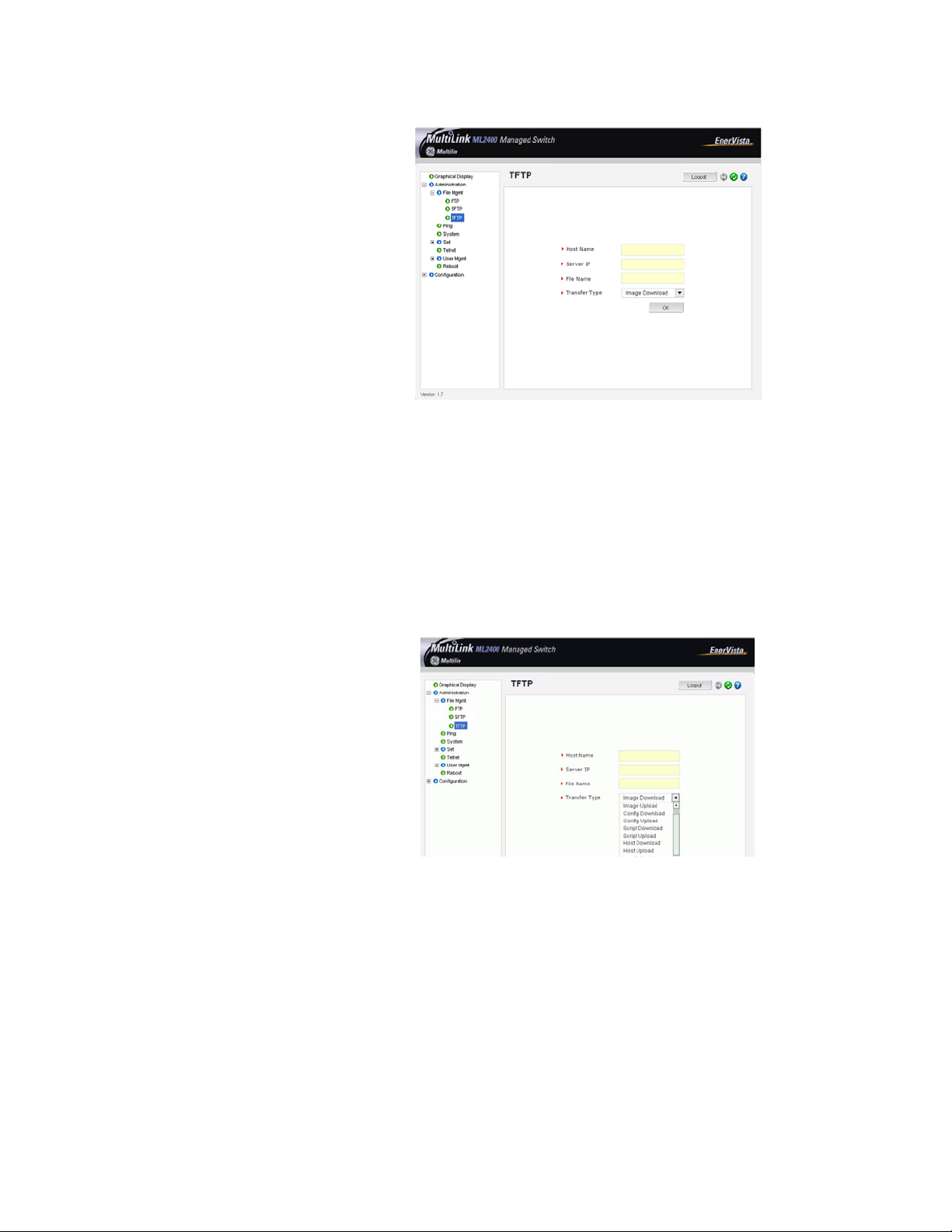
CHAPTER 5: IP ADDRESSING SYSTEM CONFIGURATION
This process can also be used to update new software to the managed MultiLink switches.
Before the software is updated, it is advised to save the configurations. Reloading of the
configuration is not usually necessary, but in certain situations it may be needed, and it is
recommended that you save configurations before a software update. Make sure to
reboot the switch after a new configuration is loaded.
Using the File Mgmt (management) menus, several operations can take place as shown in
the figure below and summarized below. These operations can take place from the FTP or
TFTP servers on the network as shown above.
The different operations possible with ftp, and tftp are shown below:
The file transfer operations allowed are:
1. Image Download (or Image Upload): Copy the ML1600 image from switch to
the server (or from the server to the switch). The “Image Upload” option is
commonly used to upgrade the ML1600 image on the switch.
2. Config Download (or Config Upload): Save the configuration of the switch on
the server (or load the saved configuration from the server to the switch). This
option is used to save a backup of the ML1600 configuration or restore the
configuration (in case of a disaster.)
MULTILINK ML1600 ETHERNET COMMUNICATIONS SWITCH – INSTRUCTION MANUAL 5–23
Page 86

SYSTEM CONFIGURATION CHAPTER 5: IP ADDRESSING
3. Script Download (or Script Upload): Save the necessary CLI commands used
for configuration of the switch (or upload the necessary CLI commands
needed to configure the switch). This option is used to ease the repetitive task
of configuring multiple commands or reviewing all the commands needed to
configure the ML1600.
4. Host Download (or Host Upload): Save the host information. The hosts are
created by the Configuration - Access - Host commands
5. Log Upload - Save the log file on the ftp/tftp server
To save any changes,
Z Click on the save ( ) icon.
The software will ask again if the changes need to be saved or
ignored.
Z If the changes need to be ignored, click on Cancel and reboot the
switch.
Z If the changes need to be saved, click on OK.
The following figures illustrate saving changes made after adding an SNTP server. This is
done by clicking on the Save icon to save current configuration
5–24 MULTILINK ML1600 ETHERNET COMMUNICATIONS SWITCH – INSTRUCTION MANUAL
Page 87

CHAPTER 5: IP ADDRESSING SYSTEM CONFIGURATION
5.4.7 Host Names
Instead of typing in IP addresses of commonly reached hosts, the ML1600 allows hosts to
be created with the necessary host names, IP addresses, user names, and passwords. Use
the Configuration > Access > Host menu to create host entries as shown below.
To add a host:
Z Click the Add button.
Z Fill in all the fields below to create the necessary host entries.
MULTILINK ML1600 ETHERNET COMMUNICATIONS SWITCH – INSTRUCTION MANUAL 5–25
Page 88

SYSTEM CONFIGURATION CHAPTER 5: IP ADDRESSING
To delete or edit the entries, use the delete or edit icons next to each entry shown above.
5.4.8 Erasing Configuration
Kill Config option using SWM
To erase the configuration and reset the configurations to factory defaults, you can use
the kill config option from Administration tab by selecting kill config.
Note
User also has the option to save one module from defaulting back to factory defaults by
checking the module box before issuing kill Config command.
5–26 MULTILINK ML1600 ETHERNET COMMUNICATIONS SWITCH – INSTRUCTION MANUAL
Page 89

CHAPTER 5: IP ADDRESSING SYSTEM CONFIGURATION
In the example below “system” module box has been checked. In this case after kill Config
command is issued by pressing the OK button, the Switch will perform a factory dump
restoring all the Switch settings back to factory defaults except for the “System” settings
which will be retained.
When the OK button is pressed the Switch will issue the following warning messages; and
reboot the switch for it to revert back to the factory default settings with the exceptions of
modules opted not to be defaulted.
MULTILINK ML1600 ETHERNET COMMUNICATIONS SWITCH – INSTRUCTION MANUAL 5–27
Page 90

SYSTEM CONFIGURATION CHAPTER 5: IP ADDRESSING
Here is a list of the modules and related settings that can be selected not to default back to
factory default settings.
Name Areas affected
System IP Configuration, Boot mode
User Users settings (e.g. login names, passwords)
Port
Port settings, Broadcast Protection and QoS
settings
STP/RSTP STP, RSTP settings
Port-Security Port Security settings
Port-Mirror Port Mirror settings
VLAN Port/Tag VLAN settings
ACCESS IP-Access and Host Table settings
IGMP IGMP Settings
LACP LACP settings
Kill Config option using CLI
This command is a “hidden command”; that is, the on-line help and other help functions
normally do not display this command. The syntax for this command is:
kill Config
or
kill config save=module command
The kill Config command will default all the Switch settings back to factory defaults, while
the kill config save=module will default all with the exception of module selected.
Available modules are: system, user, acces, port, vlan, ps, mirror, lacp, slp, and igmp.
5–28 MULTILINK ML1600 ETHERNET COMMUNICATIONS SWITCH – INSTRUCTION MANUAL
Page 91

CHAPTER 5: IP ADDRESSING SYSTEM CONFIGURATION
It is recommended to save the configuration (using saveconf command discussed above)
before using the kill config command. The following two examples illustrate how to erase
all the Switch’s configuration using the kill config command and the second example
illustrates how to erase all the Switch’s configuration with the exception of ‘system’
configuration.
ML1600# kill config
Do you want to erase the configuration?
['Y' or 'N'] Y
Successfully erased configuration...Please reboot.
ML1600# kill config save=system
Do you want to erase the configuration?
['Y' or 'N'] Y
Successfully erased configuration...Please reboot.
Once the configuration is erased, please reboot the switch for the changes to take effect .
MULTILINK ML1600 ETHERNET COMMUNICATIONS SWITCH – INSTRUCTION MANUAL 5–29
Page 92

IPV6 CHAPTER 5: IP ADDRESSING
5.5 IPv6
This section explains how to access the GE MultiLink switches using IPv6 instead of IPv4
addressing. IPv6 provides a much larger address space and its use is often required.
Assumptions
It is assumed here that the user is familiar with IP addressing schemes and has other
supplemental material on IPv6, configuration, routing, setup and other items related to
IPv6. This user guide does not discuss these details.
5.5.1 Introduction to IPv6
IPv6 is short for "Internet Protocol Version 6". IPv6 is the "next generation" protocol or IPng
and was recommended to the IETF to replace the current version Internet Protocol, IP
Version 4 ("IPv4"). IPv6 was recommended by the IPv6 (or IPng) Area Directors of the
Internet Engineering Task Force at the Toronto IETF meeting on July 25, 1994 in RFC 1752:
The Recommendation for the IP Next Generation Protocol. The recommendation in
question, was approved by the Internet Engineering Steering Group and a proposed
standard was created on November 17, 1994. The core set of IPv6 protocols was created
as an IETF draft standard on August 10, 1998.
IPv6 is a new version of IP, designed to be an evolutionary step from IPv4. It is a natural
increment to IPv4. It can be installed as a normal software upgrade in internet devices and
is interoperable with the current IPv4. Its deployment strategy is designed to have no
dependencies. IPv6 is designed to run well on high performance networks (e.g. Gigabit
Ethernet, OC-12, ATM, etc.) and at the same time still be efficient on low bandwidth
networks (e.g. wireless). In addition, it provides a platform for the new level of internet
functionality that will be required in the near future.
IPv6 includes a transition mechanism designed to allow users to adopt and deploy it in a
highly diffuse fashion, and to provide direct interoperability between IPv4 and IPv6 hosts.
The transition to a new version of the Internet Protocol is normally incremental, with few or
no critical interdependencies. Most of today's internet uses IPv4, which is now nearly
twenty years old. IPv4 has been remarkably resilient in spite of its age, but it is beginning
to have problems. Most importantly, there is a growing shortage of IPv4 addresses, which
are needed by all new machines added to the Internet.
IPv6 fixes a number of problems in IPv4, such as the limited number of available IPv4
addresses. It also adds many improvements to IPv4 in areas such as routing and network
auto configuration. IPv6 is expected to gradually replace IPv4, with the two coexisting for a
number of years during the transition period.
5.5.2 What’s changed in IPV6?
The changes from IPv4 to IPv6 fall primarily into the following categories:
• Expanded Routing and Addressing Capabilities – IPv6 increases the IP address size
from 32 bits to 128 bits, to support more levels of addressing hierarchy, a much
greater number of addressable nodes, and simpler auto-configuration of
5–30 MULTILINK ML1600 ETHERNET COMMUNICATIONS SWITCH – INSTRUCTION MANUAL
Page 93

CHAPTER 5: IP ADDRESSING IPV6
addresses. The scalability of multicast routing is improved by adding a "scope"
field to multicast addresses.
• A new type of address called an "anycast address" is defined, that identifies sets of
nodes where a packet sent to an anycast address is delivered to one of these
nodes. The use of anycast addresses in the IPv6 source route allows nodes to
control the path along which their traffic flows.
• Header Format Simplification - Some IPv4 header fields have been dropped or
made optional, to reduce the common-case processing cost of packet handling
and to keep the bandwidth cost of the IPv6 header as low as possible despite the
increased size of the addresses. Even though the IPv6 addresses are four times
longer than the IPv4 addresses, the IPv6 header is only twice the size of the IPv4
header.
• Improved Support for Options - Changes in the way IP header options are encoded
allow more efficient forwarding, less stringent limits on the length of options, and
greater flexibility for introducing new options in the future.
• Quality-of-Service Capabilities - A new capability is added to enable the labeling of
packets belonging to particular traffic "flows" for which the sender requests
special handling, such as non-default quality of service or "real- time" service.
• Authentication and Privacy Capabilities - IPv6 includes the definition of extensions
which provide support for authentication, data integrity, and confidentiality. This is
included as a basic element of IPv6 and will be included in all implementations.
5.5.3 IPv6 Addressing
IPv6 addresses are 128-bits long and are identifiers for individual interfaces and sets of
interfaces. IPv6 addresses of all types are assigned to interfaces, not nodes. Since each
interface belongs to a single node, any of that node's interface’s unicast addresses may be
used as an identifier for the node. A single interface may be assigned multiple IPv6
addresses of any type.
There are three types of IPv6 addresses. These are unicast, anycast, and multicast. Unicast
addresses identify a single interface. Anycast addresses identify a set of interfaces such
that a packet sent to an anycast address will be delivered to one member of the set.
Multicast addresses identify a group of interfaces, such that a packet sent to a multicast
address is delivered to all the interfaces in the group. There are no broadcast addresses in
IPv6. This function has been replaced by multicast addresses.
IPv6 supports addresses which are four times the number of bits as IPv4 addresses (128 vs.
32). This is 4 Billion x 4 Billion x 4 Billion (296) times the size of the IPv4 address space (232).
This works out to be:
340,282,366,920,938,463,463,374,607,431,768,211,456
This is an extremely large address space. In a theoretical sense this is approximately
665,570,793,348,866,943,898,599 addresses per square meter of the surface of the planet
Earth (assuming the earth surface is 511,263,971,197,990 square meters). In the most
pessimistic estimate this would provide 1,564 addresses for each square meter of the
surface of Earth. The optimistic estimate would allow for 3,911,873,538,269,506,102
addresses for each square meter of the surface Earth. Approximately fifteen percent of
the address space is initially allocated. The remaining 85% is reserved for future use.
MULTILINK ML1600 ETHERNET COMMUNICATIONS SWITCH – INSTRUCTION MANUAL 5–31
Page 94

IPV6 CHAPTER 5: IP ADDRESSING
Details of the addressing are covered by numerous articles on the WWW as well as other
literature, and are not covered here.
5.5.4 Configuring IPv6
The commands used for IPv6 are the same as those used for IPv4. Some of the commands
will be discussed in more details later. The only exception is the ‘ping’ command where
there is a special command for IPv6. That commands is ‘ping6’ and the syntax is as
Syntax ping6 <IPv6 address> - pings an IPv6 station.
There is also a special command to ping the status of IPv6. That command is
Syntax show ipv6 - displays the IPv6 information.
To configure IPv6, the following sequence of commands can be used:
ML1600# ipconfig ?
ipconfig : Configures the system IP address, subnet mask and gateway
Usage
ipconfig [ip=<ipaddress>] [mask=<subnet-mask>] [dgw=<gateway>]
ML1600# ipconfig ip=fe80::220:6ff:fe25:ed80 mask=ffff:ffff:ffff:ffff::
Action Parameter Missing. "add" assumed.
IPv6 Parameters Set.
ML1600# show ipv6
IPv6 Address : fe80::220:6ff:fe25:ed80 mask : ffff:ffff:ffff:ffff::
ML1600# show ipconfig
IP Address : 192.168.5.5
Subnet Mask: 255.255.255.0
Gateway Address: 192.168.5.1
IPv6 Address: fe80::220:6ff:fe25:ed80 mask : ffff:ffff:ffff:ffff::
IPv6 Gateway: ::
ML1600#
FIGURE 5–5: Configuring IPv6
In addition to the commands listed above, the commands which support IPv6 addressing
are
Syntax ftp <IPv6 address> - ftp to an IPv6 station
Example – ftp fe80::220:6ff:fe25:ed80
5–32 MULTILINK ML1600 ETHERNET COMMUNICATIONS SWITCH – INSTRUCTION MANUAL
Page 95

CHAPTER 5: IP ADDRESSING IPV6
Syntax telnet <IPv6 address> - telnet to an IPv6 station
Example – telnet fe80::220:6ff:fe25:ed80
Besides, if the end station supports IPv6 addressing (as most Linux and Windows systems
do), one can access the switch using the IPv6 addressing as shown in the example below
http://fe80::220:6ff:fe25:ed80
5.5.5 List of commands in this chapter
Syntax ipconfig [ip=<ip-address>] [mask=<subnet-mask>] [dgw=<gateway>] [add|del]
– configure an IPv6 address. The add/delete option can be used to add or delete IPv4/IPv6
addresses.
Syntax show ipconfig – display the IP configuration information – including IPv6 address
Syntax ping6 <IPv6 address> - pings an IPv6 station
Syntax show ipv6 - displays the IPv6 information
Syntax ftp <IPv6 address> - ftp to an IPv6 station
Syntax telnet <IPv6 address> - telnet to an IPv6 station.
MULTILINK ML1600 ETHERNET COMMUNICATIONS SWITCH – INSTRUCTION MANUAL 5–33
Page 96

IPV6 CHAPTER 5: IP ADDRESSING
5–34 MULTILINK ML1600 ETHERNET COMMUNICATIONS SWITCH – INSTRUCTION MANUAL
Page 97

GE Consumer & Industrial
Multilin
Multilink ML1600
Ethernet Communications Switch
Chapter 6: Access Considerations
Access Considerations
6.1 Securing Access
6.1.1 Description
This section explains how the access to the MultiLink family of switches can be secured.
Further security considerations are also covered such as securing access by IP address or
MAC address.
Note
6.1.2 Passwords
It is assumed here that the user is familiar with issues concerning security as well as
securing access for users and computers on a network. Secure access on a network can
be provided by authenticating against an allowed MAC address as well as IP address.
The GE MultiLink family of switches have a factory default password for the manager as
well as the operator account. Passwords can be changed from the user ID by using the
set password command.
For example:
ML1600# set password
Enter Current Password:*******
Enter New Password:*******
Confirm New Password:*******
Password has been modified successfully
ML1600#
Other details on managing users and the passwords are covered in User MGMNT on page
1–12.
MULTILINK ML1600 ETHERNET COMMUNICATIONS SWITCH – INSTRUCTION MANUAL 6–1
Page 98

SECURING ACCESS CHAPTER 6: ACCESS CONSIDERATIONS
6.1.3 Port Security Feature
The port security feature can be used to block computers from accessing the network by
requiring the port to validate the MAC address against a known list of MAC addresses. This
port security feature is provided on an Ethernet, Fast Ethernet , or Gigabit Ethernet port. In
case of a security violation, the port can be configured to go into the disable mode or drop
mode. The disable mode disables the port, not allowing any traffic to pass through. The
drop mode allows the port to remain enabled during a security violation and drop only
packets that are coming in from insecure hosts. This is useful when there are other network
devices connected to the MultiLink family of switches. If there is an insecure access on the
secondary device, the MultiLink family of switches allow the authorized users to continue
to access the network; the unauthorized packets are dropped preventing access to the
network.
Note
Network security hinges on the ability to allow or deny access to network resources. This
aspect of secure network services involves allowing or disallowing traffic based on
information contained in packets, such as the IP address or MAC address. Planning for
access is a key architecture and design consideration. For example, which ports are
configured for port security? Normally rooms with public access (e.g. lobby, conference
rooms, etc.) should be configured with port security. Once that is decided, the next few
decisions are: Who are the authorized and unauthorized users? What action should be
taken against authorized as well as unauthorized users? How are the users identified as
authorized or unauthorized?
6–2 MULTILINK ML1600 ETHERNET COMMUNICATIONS SWITCH – INSTRUCTION MANUAL
Page 99

CHAPTER 6: ACCESS CONSIDERATIONS CONFIGURING PORT SECURITY THROUGH THE COMMAND LINE INTERFACE
6.2 Configuring Port Security through the Command Line Interface
6.2.1 Commands
To configure port security, login as a level 2 user or as a manager. Once logged in, get to
the port-security configuration level to setup and configure port security with the following
command syntax:
configure port-security
port-security
For example, using the
ML1600# configure port-security
ML1600(port-security)##
Alternately, the port-security command can also be used to enter the port-security
configuration mode:
ML1600# port-security
ML1600#(port-security)##
From the port security configuration mode, the switch can be configured to:
configure port-security command:
1. Auto-learn the MAC addresses.
2. Specify individual MAC addresses to allow access to the network.
3. Validate or change the settings.
The command syntax for the above actions are:
allow mac=<address|list|range>
port=<num|list|range>
learn port=<number-list> <enable|disable>
show port-security
action port=<num|list|range>
<none|disable|drop>
signal port=<num|list|range>
<none|log|trap|logandtrap>
ps <enable|disable>
remove mac=<all|address|list|range>
port=<num|list|range>
signal port=<num|list|range>
<none|log|trap|logandtrap>
Where the following hold:
•
allow mac - configures the switch to setup allowed MAC addresses on specific
ports
•
learn port - configures the switch to learn the MAC addresses associated with
specific port or a group of ports
show port-security - shows the information on port security programmed or
•
learnt
•
action port - specifies the designated action to take in case of a non
authorized access
•
ps - port security - allows port security to be enable or disabled
MULTILINK ML1600 ETHERNET COMMUNICATIONS SWITCH – INSTRUCTION MANUAL 6–3
Page 100

CONFIGURING PORT SECURITY THROUGH THE COMMAND LINE INTERFACE CHAPTER 6: ACCESS CONSIDERATIONS
• remove mac - removes specific or all MAC addresses from port security lookup
signal port=<num|list|range> - observe list of specified ports and notify if
•
there is a security breach on the list of port specified. The signal can be a log entry,
a trap to the trap receiver specified as part of the SNMP commands (where is that
specified) or both
Note
There is a limitation of 200 MAC addresses per port and 500 MAC addresses per switch for
port security.
Note
All commands listed above must be executed under the port security configuration mode.
Let's look at a few examples. The following command allows specific MAC addresses on a
specified port. No spaces are allowed between specified MAC addresses.
ML1600(port-security)## allow
mac=00:c1:00:7f:ec:00,00:60:b0:88:9e:00 port=18
The following command sequence sets the port security to learn the MAC addresses. Note
that a maximum of 200 MAC addresses can be learned per port, to a maximum of 500 per
switch. Also, the
action on the port must be set to none before the port learns the MAC
address information.
ML1600(port-security)## action port=9,10 none
ML1600(port-security)##
learn port=9,10 enable
The following command sequence enables and disables port security
ML1600(port-security)## ps enable
Port Security is already enabled
ML1600(port-security)## ps disable
Port Security Disabled
ML1600 ps enable
Port Security Enabled
6–4 MULTILINK ML1600 ETHERNET COMMUNICATIONS SWITCH – INSTRUCTION MANUAL
 Loading...