

Page 1
Installation Over the Range
MFL37192911
Instructions Microwave Oven
BEFORE YOU BEGIN
Read these instructions completely and carefully.
•
IMPORTANT – Save these
instructions for local inspector’s use.
•
IMPORTANT – Observe all
governing codes and ordinances.
• Note to Installer – Be sure to leave these
instructions with the Consumer.
• Note to Consumer – Keep these
instructions for future reference.
• Skill level – Installation of this appliance requires
basic mechanical and electrical skills.
• Proper installation is the responsibility of the installer.
• Product failure due to improper installation is not
covered under the Warranty.
English/French/Spanish
READ CAREFULLY.
KEEP THESE INSTRUCTIONS.
31-7000132 Rev. 0 07-20 GEA
Page 2
Installation Instructions
DANGER
This is the safety alert symbol. This symbol alerts you to potential hazards that can kill or hurt you and others.
All safety messages will follow the safety alert symbol and the word “DANGER”, “WARNING”, or “CAUTION”. These
words are defined as:
Indicates a hazardous situation which, if not avoided, will result in death or serious injury.
WARNING
CAUTION
Indicates a hazardous situation which, if not avoided, could result in death or serious injury.
Indicates a hazardous situation which, if not avoided, could result in minor or moderate injury.
IMPORTANT SAFETY INSTRUCTIONS
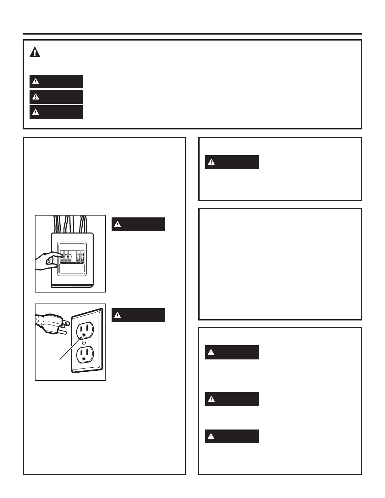
A qualified electrician must perform a ground
continuity check on the wall receptacle before
beginning the installation to ensure that the
outlet box is properly grounded. If not properly
grounded, or if the wall receptacle does not meet
electrical requirements noted (under ELECTRICAL
REQUIREMENTS), a qualified electrician should be
employed to correct any deficiencies.
WARNING
Risk of Electric Shock.
Can cause injury or
death: Remove house
fuse or
open circuit breaker
before beginning
installation to avoid
severe or fatal shock
injury.
WARNING
RISK OF ELECTRIC SHOCK
WARNING
cut, deform or remove any of the prongs from the
power cord. Do not use with an extension cord.
Failure to comply may cause fire.
Can cause injury or death: DO
NOT, under any circumstances,
ELECTRICAL REQUIREMENTS
Product rating is 120 volts AC, 60 Hertz, 13 amps
and 1.5 kilowatts. This product must be connected to
a supply circuit of the proper voltage and frequency.
Wire size must conform to the requirements of
the National Electrical Code or the prevailing local
code for this kilowatt rating. The power supply cord
and plug should be brought to a separate 15- to
20-ampere branch circuit single grounded outlet. The
outlet box should be located in the cabinet above
the microwave oven. The outlet box and supply
circuit should be installed by a qualified electrician
and conform to the National Electrical Code or the
prevailing local code.
Risk of Electric
Shock. Can cause
Ensure
proper
ground
exists before
use
The power cord of this appliance is equipped
with a three-prong (grounding) plug which mates
with a standard three-prong (grounding) wall
receptacle to minimize the possibility of electric
shock hazard from this appliance.
Where a standard two-prong wall receptacle is
encountered, it must be replaced with a properly
grounded three-prong wall receptacle, installed
by a qualified electrician.
injury or death: THIS
APPLIANCE MUST
BE PROPERLY
GROUNDED to avoid
severe or fatal shock.
FOR YOUR SAFETY:
CAUTION
capable of supporting the cabinet load, in addition to
the added weight of this 63–85 pound product, plus
additional oven loads of up to 50 pounds or a total
weight of 113–135 pounds.
CAUTION
arrangements such as an island or a peninsula. It must
be mounted to BOTH a top cabinet AND a wall.
CAUTION
due to excessive weight of the microwave oven) or
property damage, you will need two people to install
this microwave oven.
For personal safety,
the mounting surface must be
For personal safety, this product
cannot be installed in cabinet
To avoid the risk of personal
injury (back injury or other injuries
2 31-7000132 Rev. 0
Page 3
Installation Instructions
HOOD EXHAUST
NOTE: Read these next two pages only if you plan to vent your exhaust to the outside. If you plan to recirculate the air
back into the room, proceed to page 11. Your microwave oven is shipped with the blower motor orientation intended for
recirculating the air back into the room.
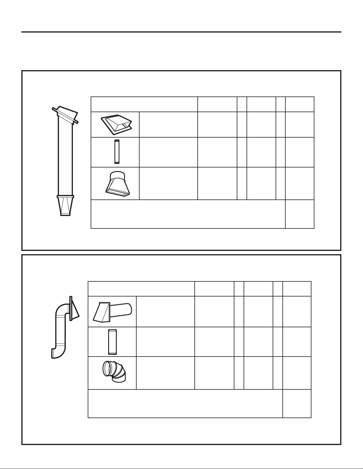
OUTSIDE TOP EXHAUST (EXAMPLE ONLY)
The following chart describes an example of one possible ductwork installation.
DUCT PIECES
EQUIVALENT
LENGTH
Roof Cap 24 Ft. X (1) = 24 Ft.
12 Ft. Straight Duct
(6” Round)
Rectangular-to-Round
Transition Adaptor*
12 Ft. X (1) = 12 Ft.
5 Ft. X (1) = 5 FT.
NUMBER
X
USED
Equivalent lengths of duct pieces are based on actual tests and
reflect requirements for good venting performance with any vent hood.
Total Length = 41 Ft.
* IMPORTANT: If a rectangular-to-round transition adaptor is used, the bottom corners of the damper
will have to be cut to fit, using the tin snips, in order to allow free movement of the damper.
OUTSIDE BACK EXHAUST (EXAMPLE ONLY)
The following chart describes an example of one possible ductwork installation.
= LENGTH
DUCT PIECES
EQUIVALENT
LENGTH
Wall Cap 40 Ft. X (1) = 40 Ft.
3 Ft. Straight
Duct (
31⁄4″ x 10″
Rectangular
90° Elbow 10 Ft. X (2) = 20 FT.
)
3 Ft. X (1) = 3 Ft.
NUMBER
X
USED
= LENGTH
Equivalent lengths of duct pieces are based on actual tests and
reflect requirements for good venting performance with any vent hood.
Total Length = 63 Ft.
NOTE: For back exhaust, care should be taken to align exhaust with space between studs, or wall
should be prepared at the time it is constructed by leaving enough space between the wall studs to
accommodate exhaust.
31-7000132 Rev. 0 3
Page 4
Installation Instructions
NOTE: If you need to install ducts, note that the total
duct length of 31⁄4″ x 10″ rectangular or 6″ diameter round
duct should not exceed 140 equivalent feet.
Outside ventilation requires a HOOD EXHAUST DUCT.
Read the following carefully.
NOTE: It is important that venting be installed using
the most direct route and with as few elbows as possible.
This ensures clear venting of exhaust and helps prevent
blockages. Also, make sure dampers swing freely and
nothing is blocking the ducts.
Exhaust connection:
The hood exhaust has been designed to mate with
a standard 31⁄4″ x 10″ rectangular duct.
If a round duct is required, a rectangular-to-round
transition adaptor must be used. Do not use less than
a 6″ diameter duct.
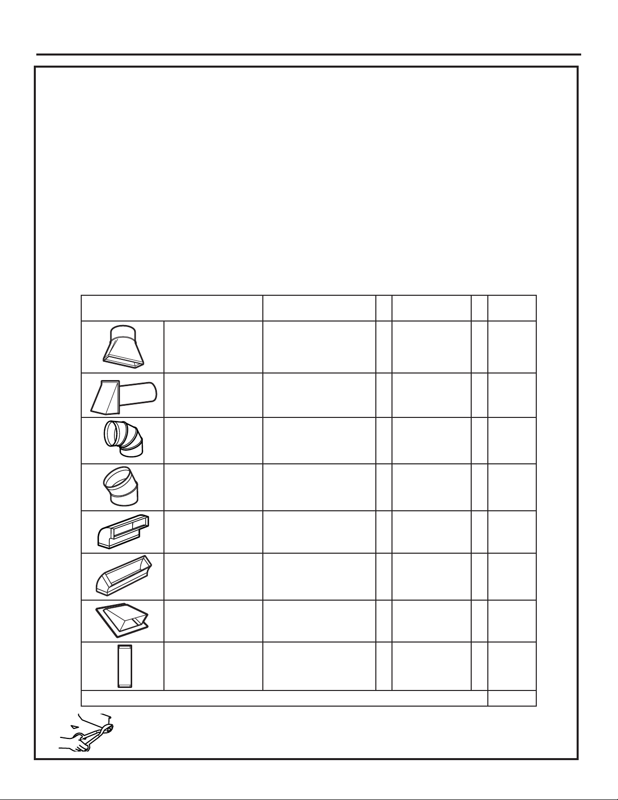
DUCT PIECES EQUIVALENT LENGTH X NUMBER USED = LENGTH
Rectangular-to-Round
Transition Adaptor*
5 Ft. X (____) = ____ Ft.
Maximum duct length:
For satisfactory air movement, the total duct length of
31⁄4″ x 10″ rectangular or 6″ diameter round duct should
not exceed 140 equivalent feet.
Elbows, transitions, wall and roof caps,
etc., present additional resistance to airflow and are
equivalent to a section of straight duct which is longer
than their actual physical size. When calculating the total
duct length, add the equivalent lengths of all transitions
and adaptors plus the length of all straight duct sections.
The chart below shows you how to calculate total
equivalent ductwork length using the approximate feet of
equivalent length of some typical ducts.
Wall Cap 40 Ft. X (____) = ____ Ft.
90° Elbow 10 Ft. X (____) = ____ Ft.
45° Elbow 5 Ft. X (____) = ____ Ft.
90° Elbow 25 Ft. X (____) = ____ Ft.
45° Elbow 5 Ft. X (____) = ____ Ft.
Roof Cap 24 Ft. X (____) = ____ Ft.
3 Ft. Straight
Duct (
31⁄4″ x 10″
Rectangular
)
1 Ft. X (____) = ____ Ft.
Total Ductwork = ____ Ft.
* IMPORTANT: If a rectangular-to-round transition
adaptor is used, the bottom corners of the
damper will have to be cut to fit, using the tin
snips, in order to allow free movement of the
damper
.
Equivalent lengths of duct pieces are based on actual tests
and reflect requirements for good venting performance with
any vent hood.
4 31-7000132 Rev. 0
Page 5
Installation Instructions
DAMAGE – SHIPMENT INSTALLATION
• If the unit is damaged in shipment, return the
unit to the store in which it was bought for repair or
replacement.
• If the unit is damaged by the customer, repair or
replacement is the responsibility of the customer.
• If the unit is damaged by the installer (if other
than the customer), repair or replacement must
be made by arrangement between customer and
installer.
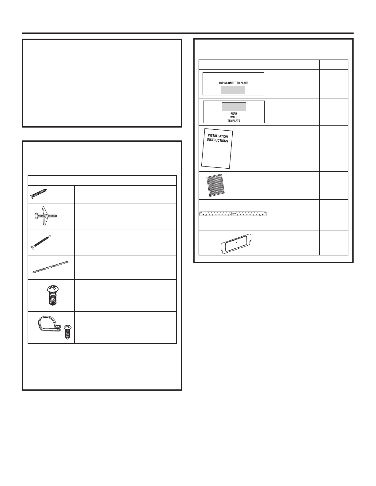
PARTS INCLUDED
HARDWARE PACKET
Part Quantity
Wood screws (1/4” x 2”) 2
Toggle bolts (and wing
nuts) (3/16” x 3”)
Self-aligning machine
screws (1/4” - 28 x 3
1/4”)
Nylon Grommet (for
metal cabinets)
2
2
1
ADDITIONAL PARTS
Part Quantity
Top Cabinet
Template
Rear Wall
Template
Installation
Instructions
Separately
Packed Grease
Filter
Mounting Plate
(for supporting
the microwave
Oven)
Cover plate (for
Room Venting
installation)
1
1
1
2
1
1
Tapping screws (for
attaching the damper
duct connector)
One power cord clamp
and One dark-colored
mounting screw (to hold
the power cord)
You will find the installation hardware contained
in a packet with the unit. Check to make sure you
have all these parts.
NOTE: Some extra parts are included.
3
1
31-7000132 Rev. 0 5
Page 6
Installation Instructions
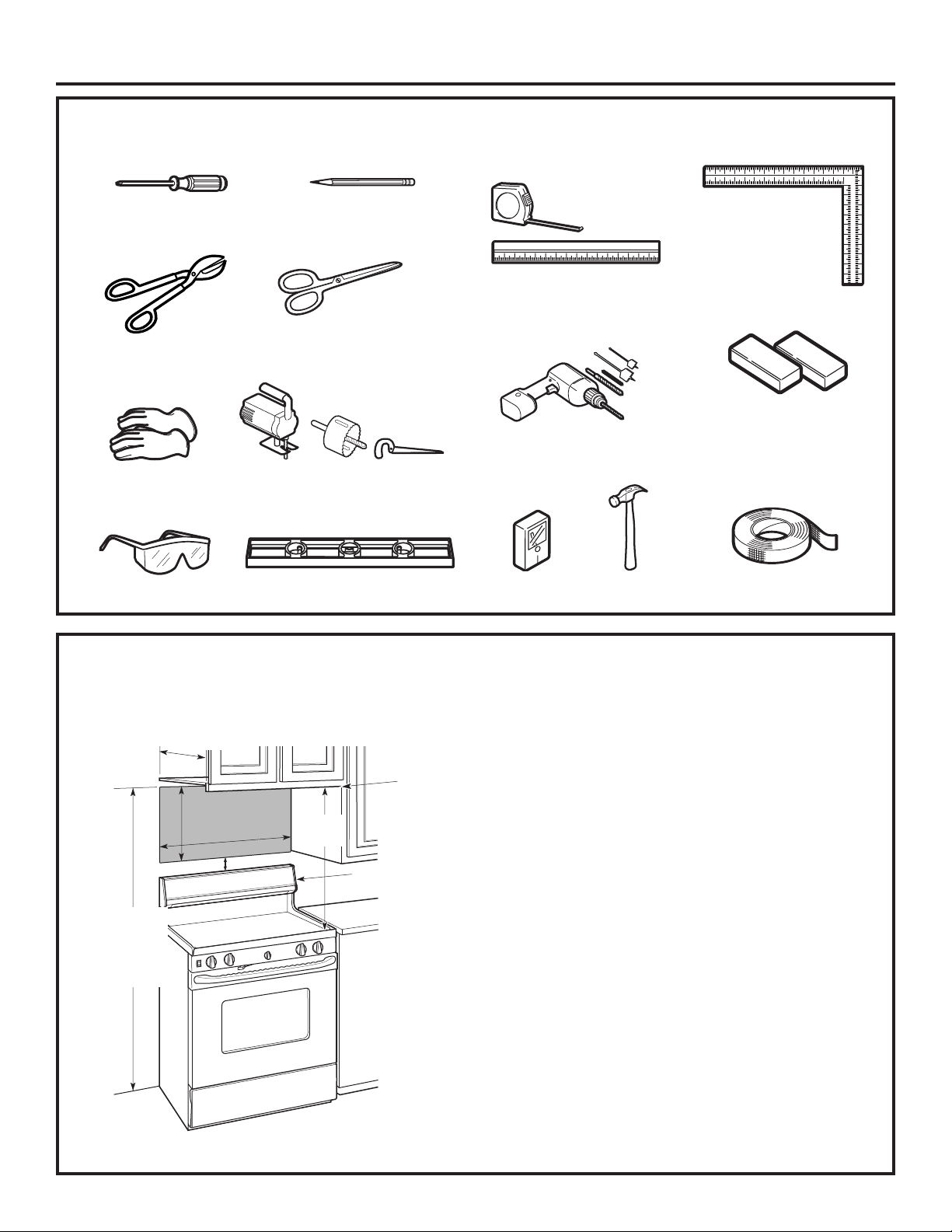
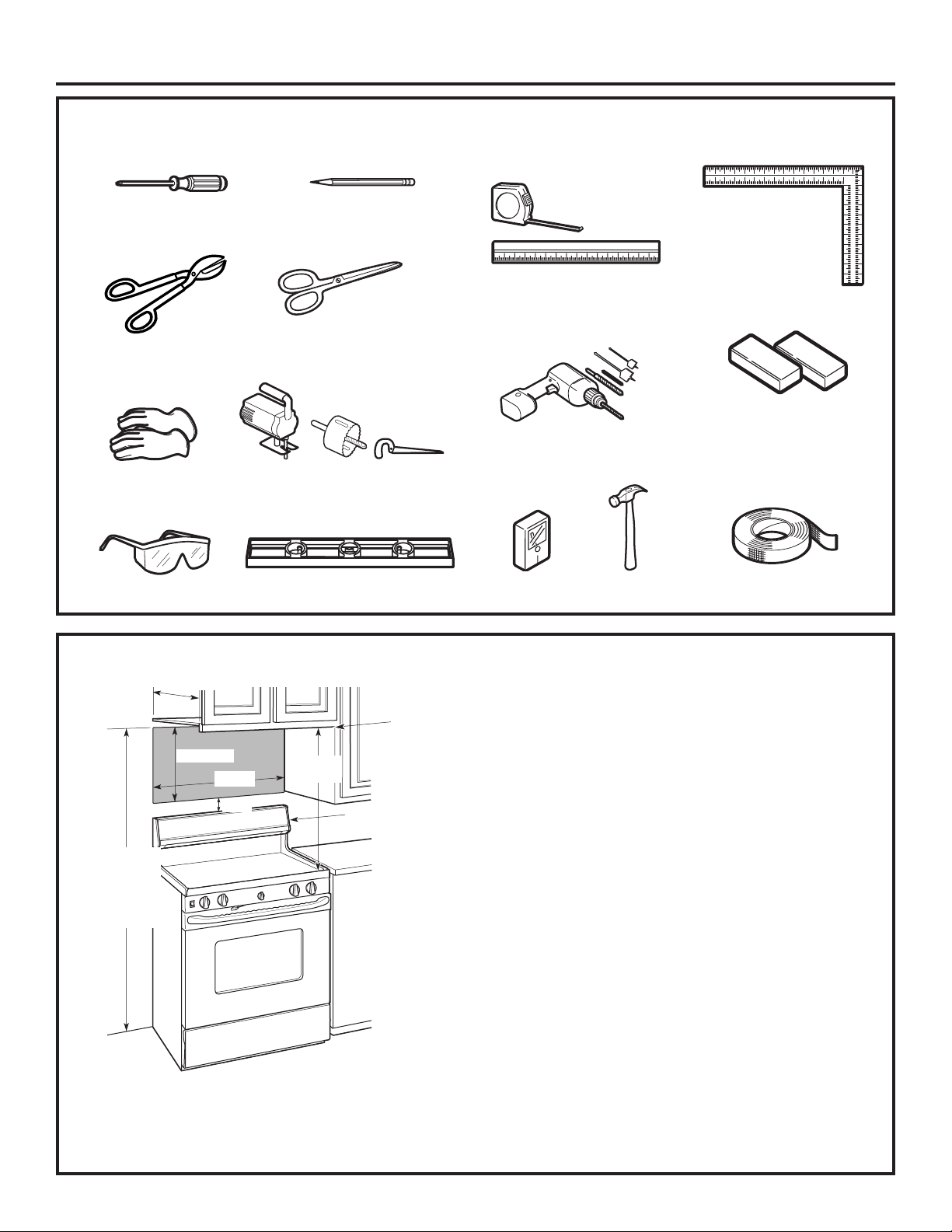
TOOLS YOU WILL NEED
#1 and #2
Phillips
screwdriver
Tin snips (for cutting
damper, if required)
Gloves
Safety goggles
Pencil
Scissors (to cut
template, if necessary)
Saw (saber, hole or keyhole)
Level
Ruler or tape measure and
straight edge
3
Electric drill with
1
⁄2″ and 5⁄8″ drill bits
Stud
finder
⁄16″, 7⁄16″,
Hammer (optional)
Carpenter square
(optional)
Filler blocks or scrap
wood pieces, if needed
for top cabinet spacing
(used on recessed
bottom cabinet
installations only)
Duct and masking
tape
MOUNTING SPACE
*13″ max.
16-1⁄2″
30″
2″
66″ or more
from the floor
to the top of
the oven
30″
min.
Bottom edge of
cabinet needs
to be 30″ or
more from the
cooking surface
Backsplash
NOTES:
• The space between the cabinets must be 30″ wide
and free of obstructions.
• This oven is for installation over ranges up to
36″ wide.
• If the space between the cabinets is greater than
30”, a Filler Panel Kit may be used to fill in the gap
between the microwave oven and the cabinets. Your
Owner’s Manual contains the kit number for your
model.
• If you are going to vent your oven to the outside, see
Hood Exhaust Section for exhaust duct preparation.
• When installing the oven beneath smooth, flat
cabinets, be careful to follow the instructions on the
top cabinet template for power cord clearance.
• * 13” max: for standard installation, 15” cabinet
depth requires additional steps using an additional
installation kit JX15BUMPWW/BB.
• For models with top venting holes: Do not allow
cabinetry or other objects to block the airflow of the vent.
• Café branded over-the-range microwaves should only
be installed over Café branded ranges. Installation over
any other range may result in surface temperatures that
can cause burns.
• All other over-the-range microwaves should not be
installed over any cooktop or range with a combined
BTU greater than 60,000 BTU.
6 31-7000132 Rev. 0
Page 7
Installation Instructions
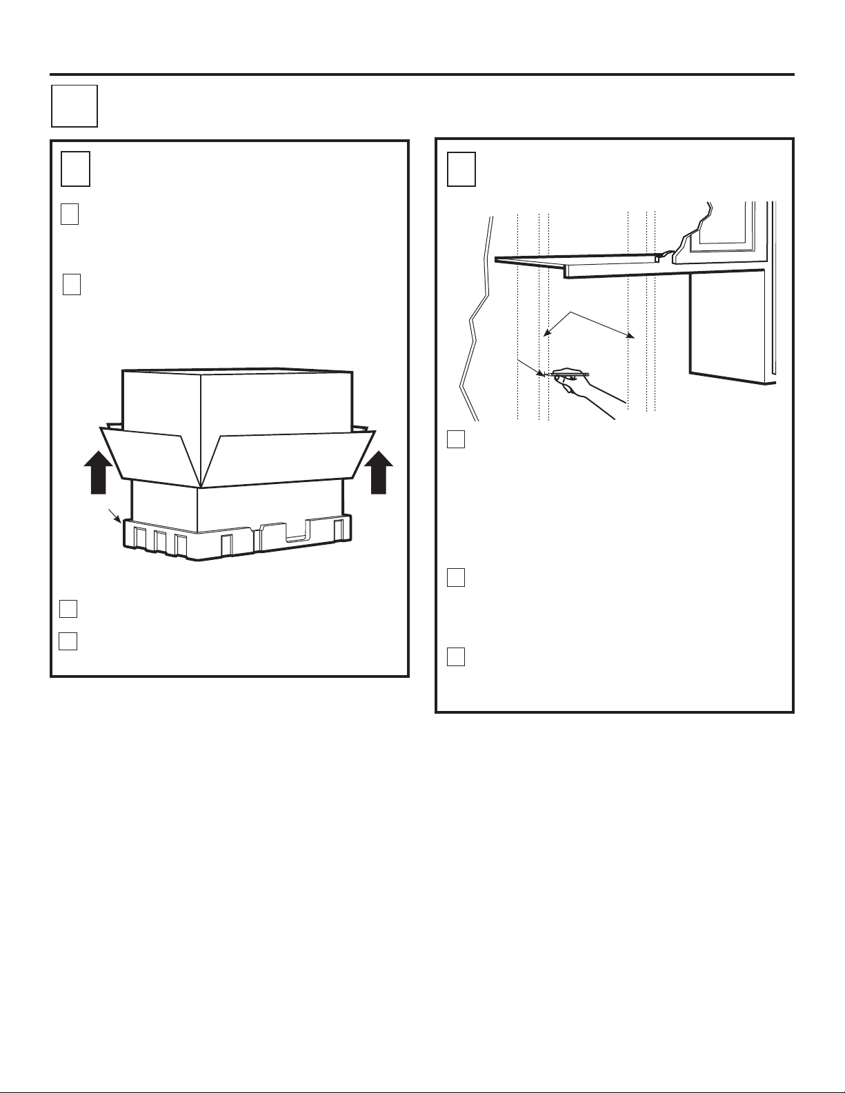
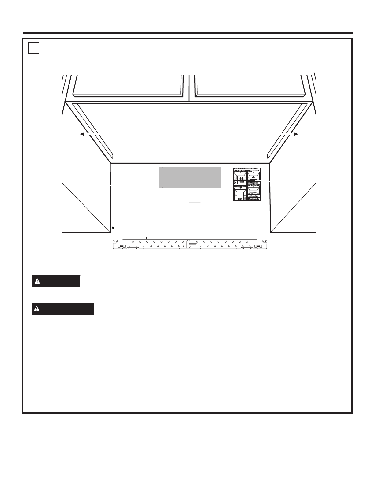
PLACEMENT OF THE MOUNTING PLATE
1
REMOVING THE MICROWAVE
A
.
OVEN FROM THE CARTON
1
Remove the installation instructions, filters, glass
tray, mounting plate, and the small hardware bag.
Do not remove the foam protecting the front of the
oven.
2
Fold back all 4 carton flaps fully against carton
sides. Then carefully roll the oven and carton over
onto the top side. The oven should be resting in
the foam.
Carton
foam
3
Pull the carton up and off the oven.
4
Set the oven upright. Remove and properly discard
plastic bags and foam packing.
B
.
FINDING THE WALL STUDS
Wall
Studs
Center
1
Find the studs, using one of the following
methods:
A. Stud finder – a magnetic device which
locates nails.
OR
B. Use a hammer to tap lightly across the
mounting surface to find a solid sound.
This will indicate a stud location.
After locating the stud(s), find the center by
2
probing the wall with a small nail to find the edges
of the stud. Then place a mark halfway between
the edges. The center of any adjacent studs
should be 16″ or 24″ from this mark.
3
Draw a line down the center of the studs.
THE MICROWAVE MUST BE CONNECTED TO
AT LEAST ONE WALL STUD.
31-7000132 Rev. 0 7
Page 8
Installation Instructions
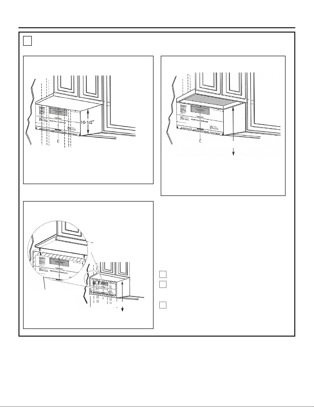
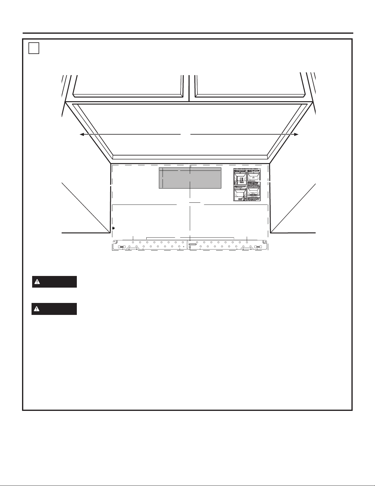
DETERMINING MOUNTING PLATE LOCATION UNDER YOUR CABINET
C
Plate Position – beneath flat bottom
cabinet
Draw a vertical line on the wall at the center of the
30” wide space. Tape the Rear Wall Template onto
the wall matching the centerline and touching the
bottom of the cabinet
Plate Position – beneath recessed
bottom cabinet with front overhang.
Draw a line on the
back wall equal to
the depth of the front
overhang
30” to Cooktop
Plate Position – beneath framed
recessed cabinet bottom
30” to Cooktop
Draw a vertical line on the wall at the center of the
30” space.
Tape the Rear Wall Template onto the wall
matching the centerline and touching the bottom
cabinet frame.
Your cabinets may have decorative trim that interferes
with the microwave installation. Remove the decorative
trim to install the microwave properly and to make it
level.
THE MICROWAVE MUST BE LEVEL
Use a level to make sure the cabinet bottom is level.
If the cabinets have a front overhang only, with no
back or side frame, install the mounting plate down the
same distance as the front overhang depth. This will
keep the microwave level.
1
Measure the inside depth of the front overhang.
Draw a horizontal line on the back wall an equal
2
distance below the cabinet bottom as the inside
depth of the front overhang.
For this type of installation with front overhang only,
3
align the Rearwall Template with this horizontal
line, not touching the cabinet bottom as described
in Step D.
8 31-7000132 Rev. 0
Page 9
Installation Instructions
MARKING THE MOUNTING HOLES
D
OPTION 1: USE PAPER REAR WALL TEMPLATE
30”
OPTION 1
NOTE: IT IS VERY IMPORTANT TO
READ AND FOLLOW THE DIRECTIONS
IN THE INSTALLATION INSTRUCTIONS
BEFORE PROCEEDING WITH THIS
REAR WALL TEMPLATE.
This Rear Wall Template serves to position the bottom
mounting plate and to locate the horizontal exhaust
outlet.
1. Use a level to check that the template is positioned
accurately.
2. Locate and mark at least one stud on the left or
right side of the centerline.
NOTE:It is important to use at least one wood
screw mounted firmly in a stud to support the weight
of the microwave. Mark two additional, evenly spaced
locations for the supplied toggle bolts.
3. Drill holes in the marked locations. Where there is
a stud, drill a 3/16" hole for wood screws. For holes
that do not line up with a stud, drill 5/8" holes for
toggle bolts.
NOTE::DO NOT INSTALL THE MOUNTING PLATE
AT THIS TIME.
4. Remove the template from the rear wall.
5. Review the Installation Instruction book for your
installation situation.
Darle vuelta a la hoja para consultar la
versión en Español.
Locate and mark holes to align with holes in the
mounting plate.
IMPORTANT:
LOCATE AT LEAST ONE STUD ON EITHER SIDE OF
THE CENTERLINE.
MARK THE LOCATION FOR 2 ADDITIONAL, EVENLY
SPACED TOGGLE BOLTS IN THE MOUNTING PLATE
AREA.
Trim the rear wall template along the dotted line.
F. CUT OUT FOR HORIZONTAL
4"
REAR WALL TEMPLATE
A
CAUTION
Wear gloves to avoid cutting fingers
on sharp edges.
WARNING
Risk of electric shock. Can cause
injury or death. Take care to not drill into electrical
wiring inside walls or cabinets.
This Rear Wall Template serves to locate the mounting
holes for the bottom mounting plate and to locate the
horizontal exhaust outlet.
1. Use a level to check that the template is positioned
accurately.
2. Locate and mark at least one stud on the left or right
side of the centerline.
NOTE: It is important to use at least one wood screw
mounted firmly in a stud to support the weight of the
microwave.
3/8" TO EDGE
12"
OUTSIDE EXHAUST
CUT HOLE THROUGH REAR WALL FOR EXHAUST ADAPTOR
CAUTION - IF EXHAUST ADAPTOR IS POSITIONED OUTSIDE
RECOMMENDED DIMENSION, GREASE-LADEN AIR WILL
DISCHARGE INTO HOUSE STRUCTURE
30” MINIMUM WIDTH REQUIRED
C
C
3. Mark the hole location on the wall using the template
4. Drill holes in the marked locations. Where there is a
NOTE: DO NOT INSTALL THE MOUNTING PLATE AT
5. Remove the template from the rear wall.
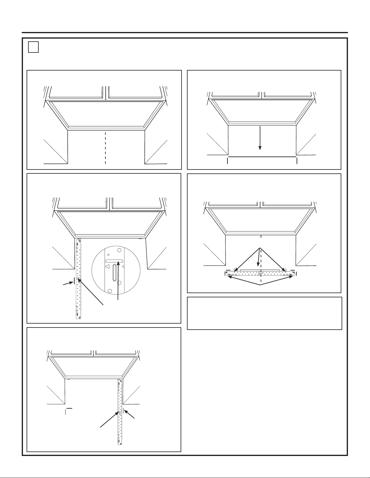
OPTION 2
NOTE: Refer to step C “DETERMINING MOUNTING PLATE LOCATION UNDER YOUR CABINET on page 10 for aligning instructions.
STEP 1: Installer uses bracket to make 2 marks. First
STEP 3: Installer uses a level to draw a horizontal line
mark is made by using the stampled slot in bracket.
that connects the two marks made with the stamped
Second mark is made on the ouside edge of bracket.
slot in the bracket.
Horizontal line
Make a mark
Make a mark here, along
here,
inside bottom of the
STEP 4: Installer uses marks to install bracket in
even with
stamped slot provided.
bottom of
correct position. The bracket is to be installed per
stamped
standard requirements (at least one wood screw
slot
mounted in a stud, two additional evenly spaced
locations for toggle bolts). Mark hole location A,B, C and
D by placing the mounting bracket on the wall as shown
in the picture. Hole C and or D must be in a WALL STUD.
STEP 2: Installer moves bracket to the other side of
the cabinets and makes 2 more marks. Marks are the
same as STEP 1, just opposite side.
Mark hole locations for A, B, C, and D.
ACD
B
Place bracket within the lines created in previous steps.
Make a
mark here,
Make a mark here, along
STEP 5: Set mounting bracket aside and drill holes at
even with
inside bottom of the
bottom of
all marked locations. If there is a stud, drill a 3/16” hole
stamped slot provided
stamped
for wood screws. For holes that do not line up with a
(same as Step 1).
slot
stud, drill a 5/8” hole for a toggle bolt.
NOTES:
- 13” Max Cabinet Depth
- 15” deep cabinets require additional steps using
an additional installation kit: JX15BUMP
Locate and mark holes to align with holes in the
mounting plate.
IMPORTANT:
LOCATE AT LEAST ONE STUD ON EITHER SIDE OF
THE CENTERLINE.
MARK THE LOCATION FOR 2 ADDITIONAL, EVENLY
SPACED TOGGLE BOLTS IN THE MOUNTING PLATE
AREA.
B
at holes A and B. Mark at least one hole location
in area C that lines up with the location of a stud. A
minimum of three holes must be used for mounting.
stud, drill a 3/16” hole for wood screws. For holes that
do not line up with a stud, drill 5/8” holes for toggle
bolts.
THIS TIME
31-7000132 Rev. 0 9
Page 10
Installation Instructions
A
C
B
MARKING THE MOUNTING HOLES
D
OPTION 2: USE METAL BRACKET AS TEMPLATE
NOTE: Refer to step C “DETERMINING MOUNTING PLATE LOCATION UNDER YOUR CABINET on page 8 for aligning instructions.
STEP 1: Draw a vertical line on the wall at the center of
the 30” space.
STEP 2: Installer uses bracket to make 2 marks. First
mark is made by using the stampled slot in bracket. Second
mark is made on the ouside edge of bracket.
STEP 4: Installer uses a level to draw a horizontal line
that connects the two marks made with the stamped slot in
the bracket.
Horizontal line
STEP 5: Installer places the mounting bracket on the wall
as shown in the picture. Draw circles on the wall at holes A
and B. Draw at least one circle in area C. At least one circle
MUST line up with a wall stud.
Mark hole locations for
A, B, and area C.
Make a mark
here on the
outside edge
of the bracket
Make a mark here, along inside
bottom of the stamped slot
provided.
STEP 3: Installer moves bracket to the other side of the
cabinets and makes 2 more marks. Marks are the same as
STEP 2, just opposite side.
Make a mark here, along
inside bottom of the
stamped slot provided
(same as Step 1).
Make a mark
here on the
outside edge of
the bracket
Place bracket within the lines created in previous steps.
STEP 6: Set mounting bracket aside and drill holes at
all marked locations. If there is a stud, drill a 3/16” hole for
wood screws. For holes that do not line up with a stud, drill a
5/8” hole for a toggle bolt.
10 31-7000132 Rev. 0
Page 11
Installation Instructions
2
This microwave oven is designed for adaptation to
the following three types of ventilation:
A. Recirculating (Non-Vented Ductless)
B. Outside Top Exhaust (Vertical Duct)
C. Outside Back Exhaust (Horizontal Duct)
A
INSTALLATION TYPES
RECIRCULATING
(NON-VENTED DUCTLESS)
(Choose A, B or C)
NOTE: Select the type of ventilation required for your
installation and proceed to that section.
B
OUTSIDE TOP EXHAUST
(VERTICAL DUCT)
Adaptor in Place
for Outside Top
Exhaust
See page 12
A Charcoal Filter Accessory Kit is required for the
non-vented exhaust. (See your Owner’s Manual for the
kit number.)
C
OUTSIDE BACK EXHAUST
(HORIZONTAL DUCT)
See page 20
See page 16
31-7000132 Rev. 0 11
Page 12
Installation Instructions
A
RECIRCULATING (Non-Vented Ductless)
INSTALLATION OVERVIEW
A1. Attach Mounting Plate to Wall
A2. Prepare Top Cabinet
A3. Check Blower Orientation
A4. Adapting Microwave Blower For Recirculation
A5. Mount the Oven
A6. Installing The Charcoal Filter
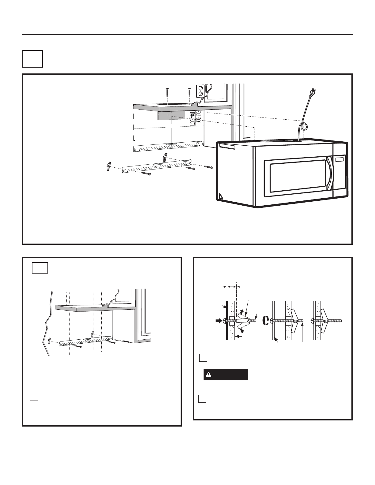
A1
ATTACH THE MOUNTING
PLATE TO THE WALL
3/8" TO EDGE
OPTION 2
STEP 1:
Installer uses bracket to make 2 marks. First
DISCHARGE INTO HOUSE STRUCTURE
C
mark is made by using the stampled slot in bracket.
Second mark is made on the ouside edge of bracket.
Horizontal line
Make a mark
STEP 4:
Make a mark here, along
here,
inside bottom of the
even with
stamped slot provided.
bottom of
stamped
slot
STEP 2:
Installer moves bracket to the other side of
the cabinets and makes 2 more marks. Marks are the
same as STEP 1, just opposite side.
Make a
mark here,
Make a mark here, along
even with
inside bottom of the
bottom of
stamped slot provided
stamped
(same as Step 1).
slot
NOTES:
- 13” Max Cabinet Depth
- 15” deep cabinets require additional steps using
an additional installation kit: JX36BUMP
C
A
C
A
12"
OPTION 1
NOTE: IT IS VERY IMPORTANT TO
READ AND FOLLOW THE DIRECTIONS
IN THE INSTALLATION INSTRUCTIONS
F. CUT OUT FOR HORIZONTAL
BEFORE PROCEEDING WITH THIS
REAR WALL TEMPLATE.
4"
OUTSIDE EXHAUST
This Rear Wall Template serves to position the bottom
mounting plate and to locate the horizontal exhaust
outlet.
CUT HOLE THROUGH REAR WALL FOR EXHAUST ADAPTOR
1. Use a level to check that the template is positioned
accurately.
2. Locate and mark at least one stud on the left or
right side of the centerline.
NOTE:
It is important to use at least one wood
screw mounted firmly in a stud to support the weight
of the microwave. Mark two additional, evenly spaced
locations for the supplied toggle bolts.
3. Drill holes in the marked locations. Where there is
a stud, drill a 3/16" hole for wood screws. For holes
that do not line up with a stud, drill 5/8" holes for
toggle bolts.
NOTE::
DO NOT INSTALL THE MOUNTING PLATE
AT THIS TIME.
4. Remove the template from the rear wall.
5. Review the Installation Instruction book for your
installation situation.
Darle vuelta a la hoja para consultar la
versión en Español.
CAUTION - IF EXHAUST ADAPTOR IS POSITIONED OUTSIDE
RECOMMENDED DIMENSION, GREASE-LADEN AIR WILL
Locate and mark holes to align with holes in the
mounting plate.
IMPORTANT:
LOCATE AT LEAST ONE STUD ON EITHER SIDE OF
THE CENTERLINE.
MARK THE LOCATION FOR 2 ADDITIONAL, EVENLY
SPACED TOGGLE BOLTS IN THE MOUNTING PLATE
AREA.
Trim the rear wall template along the dotted line.
B
B
30” MINIMUM WIDTH REQUIRED
REAR WALL TEMPLATE
D
D
IMPORTANT: Do NOT
remove the cardboard spacers
between the heat shield and
door
Place the mounting plate against the wall and
3
insert the toggle wings into the holes in the wall to
mount the plate.
CAUTION
Be careful to avoid pinching
fingers between the back of the mounting plate
and the wall.
Tighten all bolts. Pull the plate away from the wall
4
to help tighten the bolts.
A
D
B
C
Attach the plate to the wall using toggle bolts and
wood screws. At least one wood screw must be
used to attach the plate to a wall stud.
Remove the toggle wings from the bolts.
1
Insert the bolts into the mounting plate through
2
the holes designated to go into drywall and
reattach the toggle wings to 3⁄4″ onto each bolt.
To use toggle bolts:
Spacing for Toggles More
Than Wall Thickness
Toggle Wings
Mounting
Plate
Toggle
Bolt
Wall
Bolt End
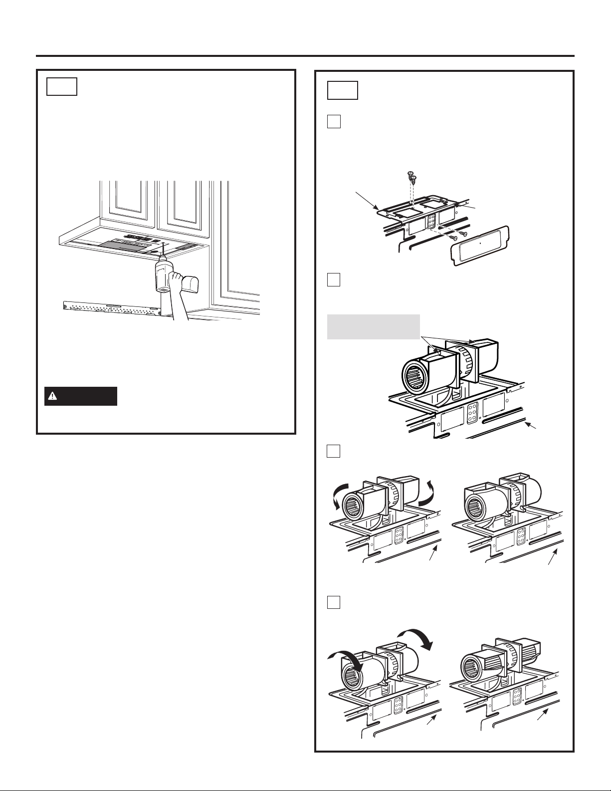
A2
USE TOP CABINET TEMPLATE
FOR PREPARATION OF TOP
CABINET
You need to drill holes for the top support screws and
a hole large enough for the power cord to fit through.
• Read the instructions on the TOP CABINET
TEMPLATE.
• Tape it underneath the top cabinet.
• Drill the holes, following the instructions on the
TOP CABINET TEMPLATE.
CAUTION
Wear safety goggles when drilling
holes in the cabinet bottom.
12 31-7000132 Rev. 0
Page 13
Installation Instructions
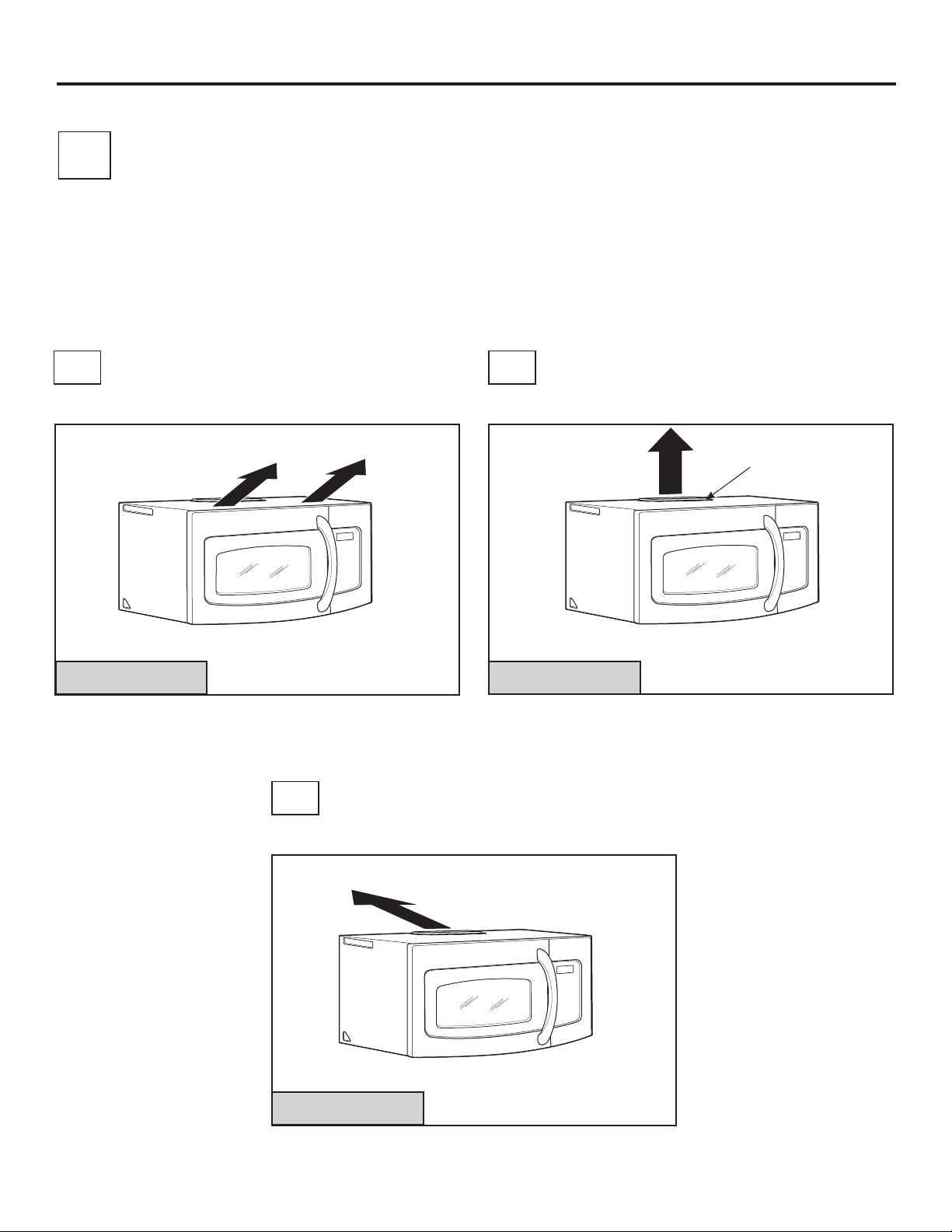
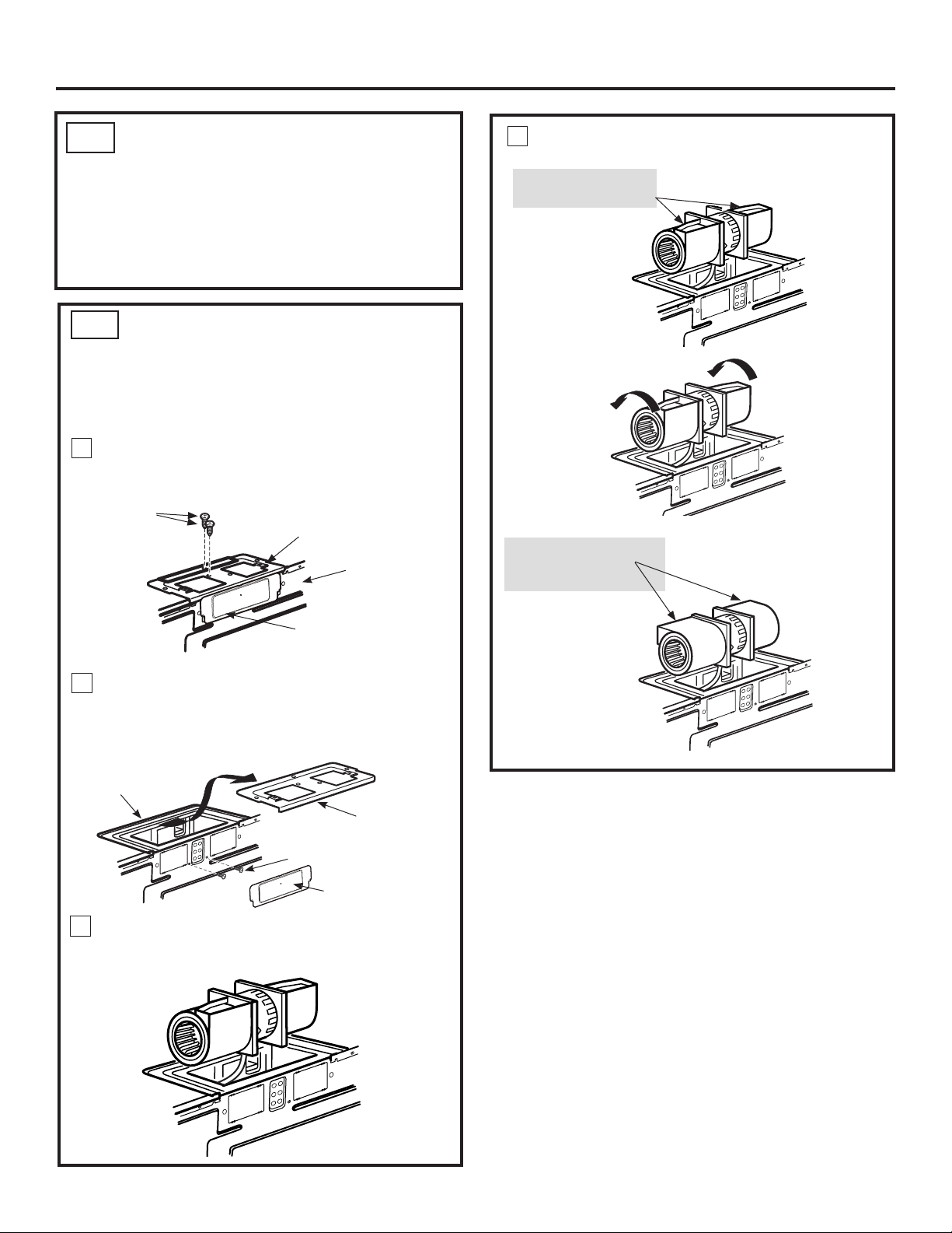
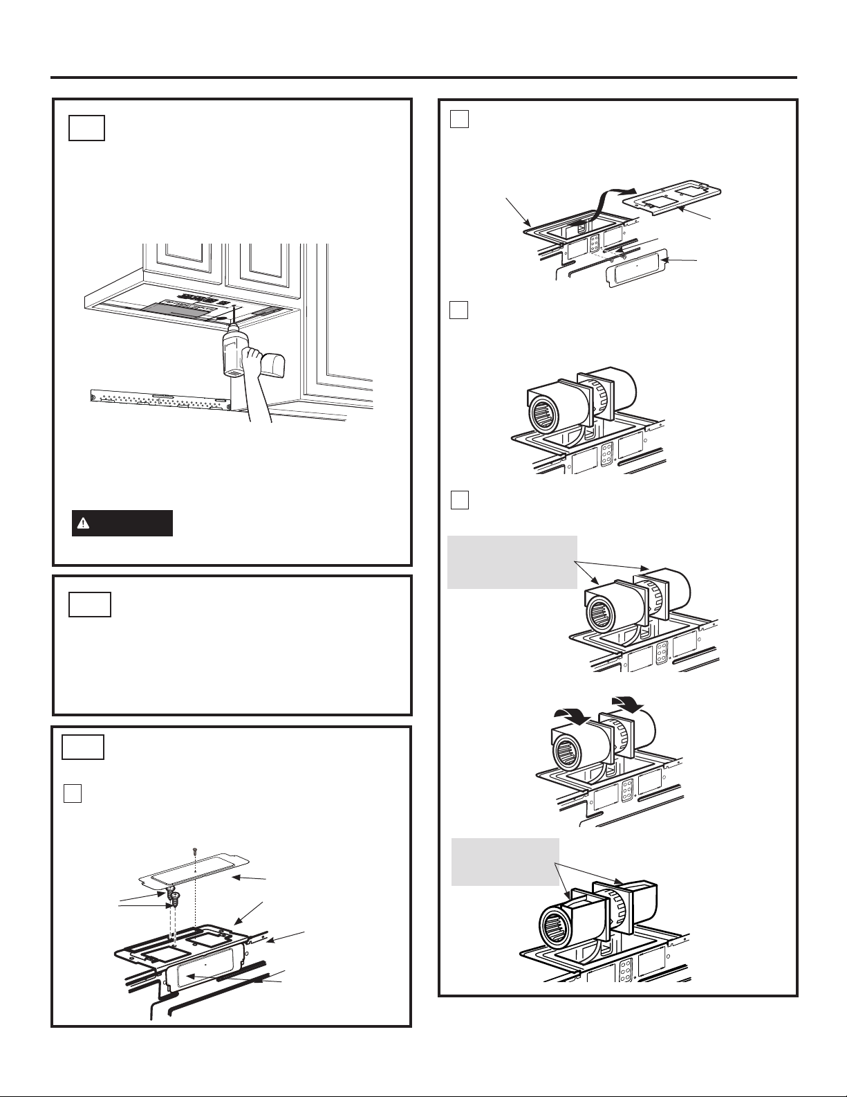
CHECK BLOWER MOTOR
A3.
ORIENTATION
The blower fan blade opening should be facing the
front of the microwave. You will have to remove the
top cover plate to check the fan blade orientation.
If the fan opening is already facing the front of the
microwave, skip to step A5. Otherwise, continue to
Step A4 to adjust the fan motor orientation.
4
Roll the blower unit 90° so that fan blade openings
are facing toward the front of the oven.
BEFORE: Fan Blade
Openings Facing Up
A4.
ADAPTING BLOWER
FOR RECIRCULATION
NOTE: The exhaust adaptor with damper is not
needed for recirculating models. You may want to
save them for possible future use.
Remove and save screws that hold blower plate
1
to the oven.
Blower Plate Screws
Blower Plate
Back of
Oven
Cover Plate
Slide the blower plate from under its retaining
2
flange and lift it off. Remove the cover plate
installed on the back. Remove and save screws
that hold blower unit to the oven.
Retaining
Flange
Blower
Blower Motor
Screws
Plate
Roll
AFTER: Fan Blade
Openings Facing
Forward
Cover Plate
Carefully pull out the blower unit. The wires
3
will extend far enough to allow you to adjust the
blower unit.
31-7000132 Rev. 0 13
Page 14
Installation Instructions
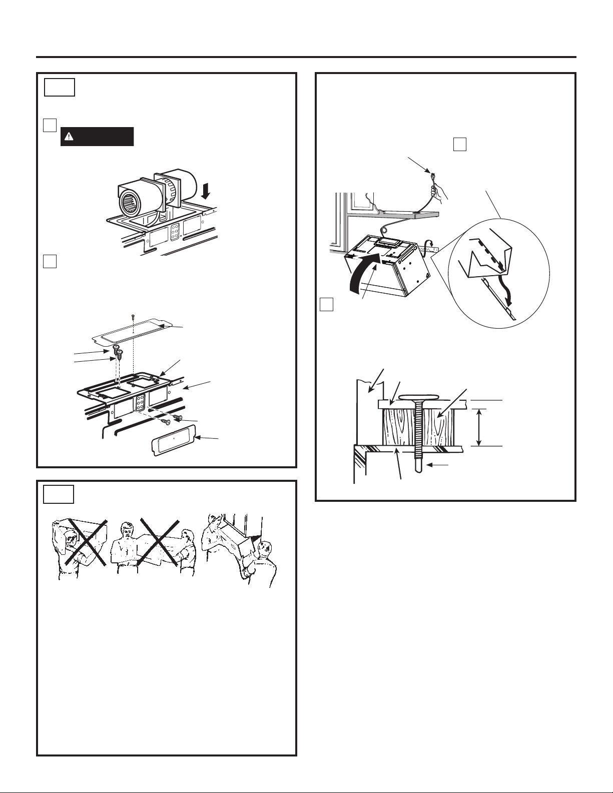
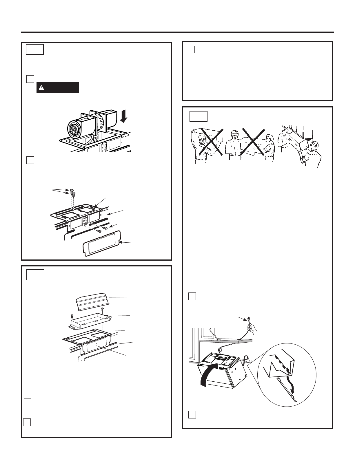
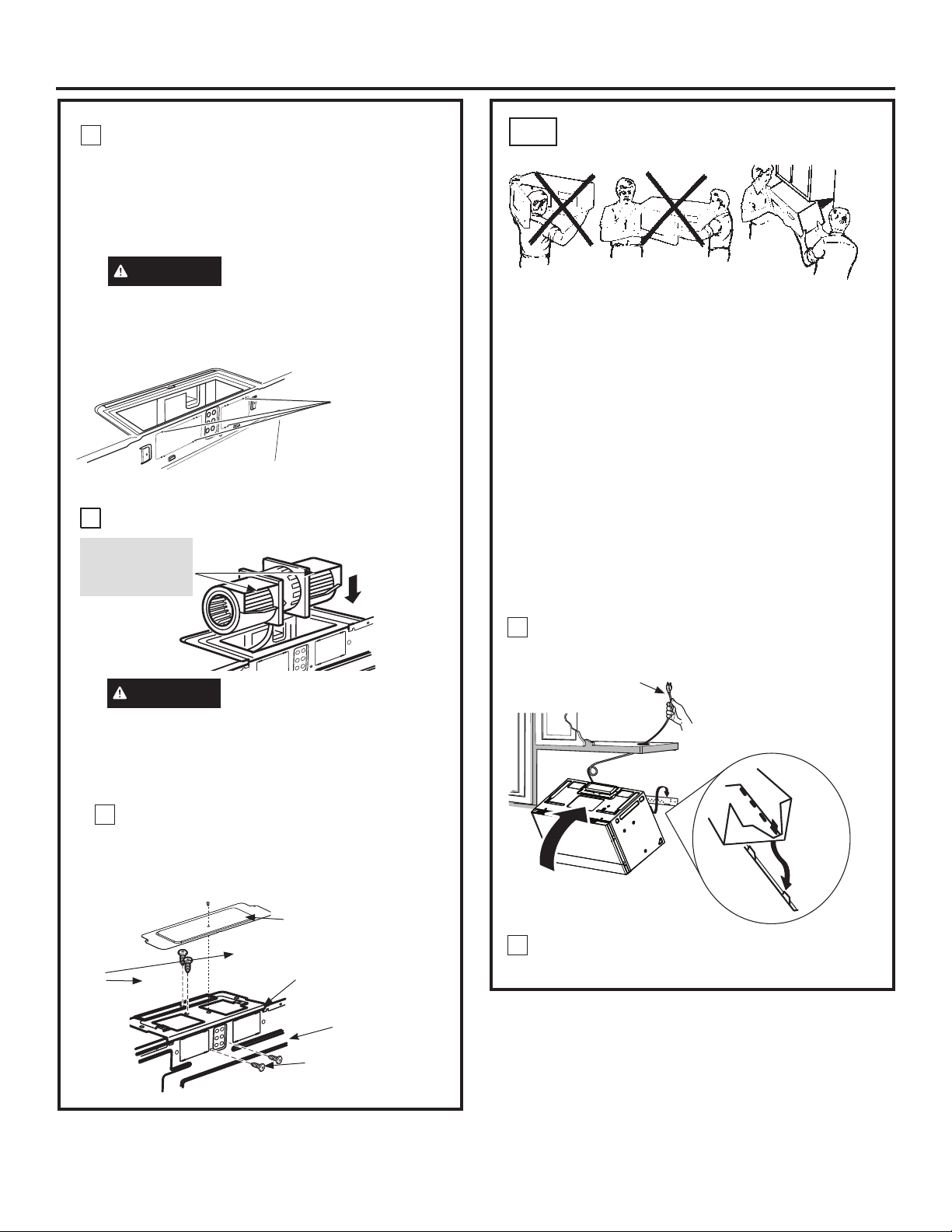
A4.
ADAPTING BLOWER FOR
RECIRCULATION (continued)
Place the blower unit back into the opening.
5
CAUTION
blower unit wiring. Make sure the wires are
not pinched.
Replace blower motor screws removed in Step 2.
6
Slide cover plate into position on the back of the
unit. Replace blower plate and screws removed in
Step 1. Attach second cover plate on blower plate
(including one screw).
Blower
Plate
Screws
Do not pull or stretch the
Cover Plate
Blower Plate
Back of
Oven
NOTE: When mounting
the oven, thread power
cord through hole in
bottom of top cabinet.
Keep it tight throughout
Steps 1–3. Do not pinch
cord or lift oven by pulling
cord.
2
Rotate front of oven
up against cabinet
bottom.
Cabinet Front
Cabinet Bottom Shelf
Lift oven, tilt it
1
forward and hook
slots at back bottom
edge onto two lower
tabs of mounting plate.
Filler Block
Blower Motor Screws
Cover Plate
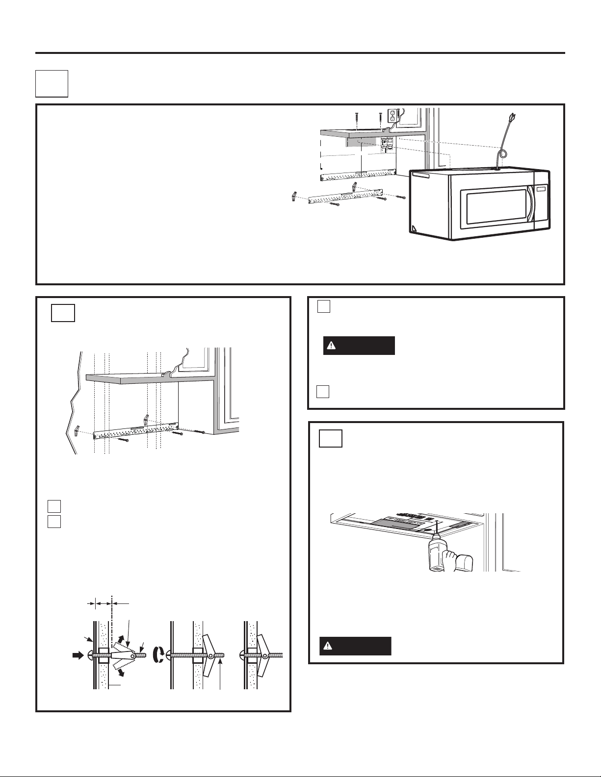
A5.
FOR EASIER INSTALLATION AND PERSONAL
SAFETY, WE RECOMMEND THAT TWO PEOPLE
INSTALL THIS OVEN.
MOUNT THE OVEN
IMPORTANT: Do not grip or use handle
during installation.
NOTE: If your cabinet is metal, use the nylon
grommet around the power cord hole to prevent
cutting of the cord.
NOTE: We recommend using filler blocks if the
cabinet front hangs below the cabinet bottom shelf.
IMPORTANT: If filler blocks are not used,
case damage may occur from over
tightening screws.
Equivalent to
Depth of Cabinet
Recess
Self-Aligning Screw
Oven Top
14 31-7000132 Rev. 0
Page 15
Installation Instructions
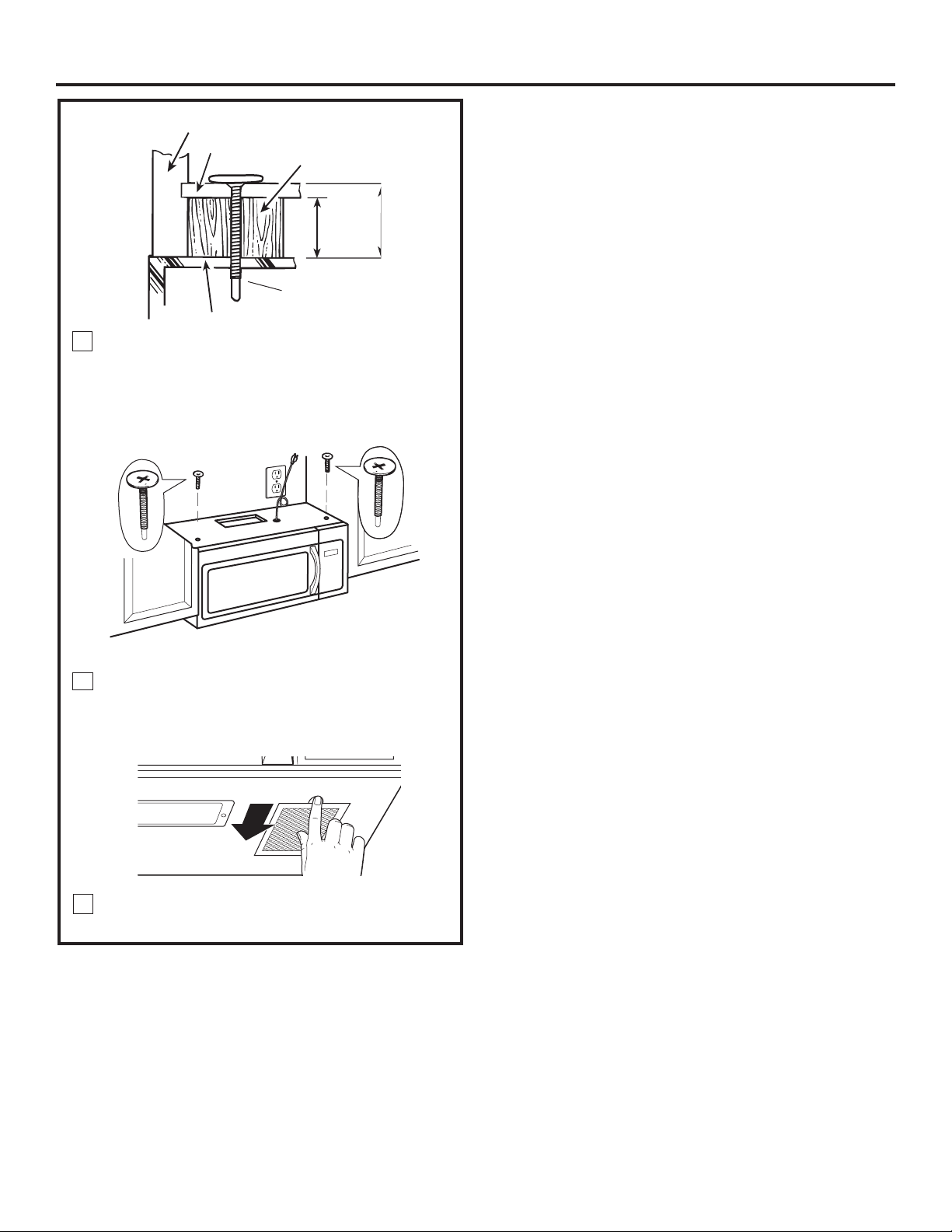
A4.
MOUNT THE OVEN
(continued)
3
Attach the oven to the top cabinet by inserting
2 self-aligning screws through outer top cabinet
holes. Turn two full turns on each screw. Be
sure to keep power cord tight. Be careful not
to pinch the cord, especially when mounting
flush to bottom of cabinet.
4
Tighten the two screws to the top of the oven
completely. (While tightening screws, hold
the oven in place against the wall and the top
cabinet.)
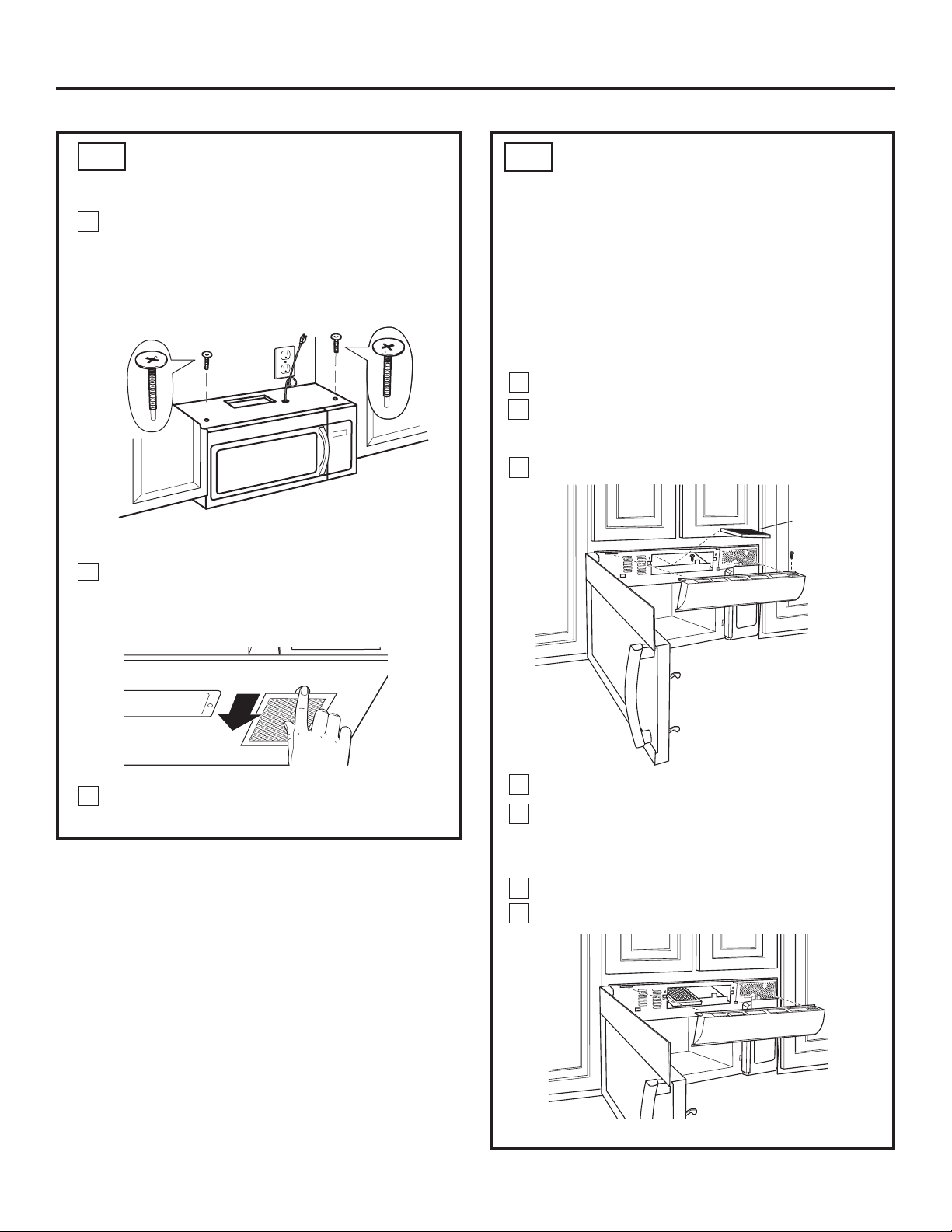
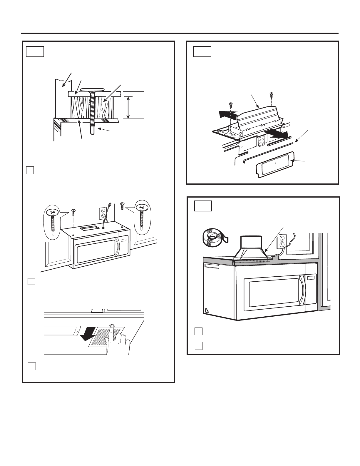
A6.
WHEN REPLACING THE
CHARCOAL FILTER
If the model is not vented to the outside, the air will
be recirculated through a disposable charcoal filter
that helps remove smoke and odors.
The charcoal filter should be replaced when it is
noticeably dirty or discolored (usually after 6 to
12 months, depending on hood usage). See your
Owner’s Manual for the filter kit number.
To replace the charcoal filter:
Open the microwave door.
1
Remove 2 screws from the top of the grille. (You
2
may need to open the cabinet doors to remove the
screws.
Slide the grille to the left and forward to remove.
3
Charcoal
Filter
Slide the old filter down and out to remove it.
Install grease filters. See the Owner’s Manual
5
packed with the oven.
31-7000132 Rev. 0 15
4
Remove plastic and other outer wrapping from
5
the new filter and install the new filter. When
properly installed, the wire mesh of the filter
should be visible from the front.
6
Replace the grille and the 2 screws.
7
Close the door.
Insert filter mesh-side up
Page 16
Installation Instructions
B
INSTALLATION OVERVIEW
B1. Attach Mounting Plate to Wall
B2. Prepare Top Cabinet
B3. Check Motor Orientation
B4. Adapting For Outside Ventilation
B5. Assemble and Install Adaptor
B6. Mount the Microwave
B7. Adjust The Exhaust Adaptor
B8. Connecting Duckwork
OUTSIDE TOP EXHAUST
(Vertical Duct)
3/8" TO EDGE
4"
D
12"
F. CUT OUT FOR HORIZONTAL
OUTSIDE EXHAUST
CUT HOLE THROUGH REAR WALL FOR EXHAUST ADAPTOR
CAUTION - IF EXHAUST ADAPTOR IS POSITIONED OUTSIDE
RECOMMENDED DIMENSION, GREASE-LADEN AIR WILL
DISCHARGE INTO HOUSE STRUCTURE
30” MINIMUM WIDTH REQUIRED
REAR WALL TEMPLATE
C
C
OPTION 1
NOTE: IT IS VERY IMPORTANT TO
READ AND FOLLOW THE DIRECTIONS
IN THE INSTALLATION INSTRUCTIONS
BEFORE PROCEEDING WITH THIS
REAR WALL TEMPLATE.
This Rear Wall Template serves to position the bottom
mounting plate and to locate the horizontal exhaust
outlet.
1. Use a level to check that the template is positioned
accurately.
2. Locate and mark at least one stud on the left or
right side of the centerline.
NOTE:
It is important to use at least one wood
screw mounted firmly in a stud to support the weight
of the microwave. Mark two additional, evenly spaced
locations for the supplied toggle bolts.
3. Drill holes in the marked locations. Where there is
a stud, drill a 3/16" hole for wood screws. For holes
that do not line up with a stud, drill 5/8" holes for
toggle bolts.
NOTE::
DO NOT INSTALL THE MOUNTING PLATE
AT THIS TIME.
4. Remove the template from the rear wall.
5. Review the Installation Instruction book for your
installation situation.
Darle vuelta a la hoja para consultar la
versión en Español.
Locate and mark holes to align with holes in the
mounting plate.
IMPORTANT:
LOCATE AT LEAST ONE STUD ON EITHER SIDE OF
THE CENTERLINE.
MARK THE LOCATION FOR 2 ADDITIONAL, EVENLY
SPACED TOGGLE BOLTS IN THE MOUNTING PLATE
AREA.
Trim the rear wall template along the dotted line.
B
D
B
NOTES:
- 13” Max Cabinet Depth
- 15” deep cabinets require additional steps using
an additional installation kit: JX36BUMP
C
A
STEP 1:
mark is made by using the stampled slot in bracket.
Second mark is made on the ouside edge of bracket.
Make a mark
here,
even with
bottom of
stamped
slot
STEP 2:
the cabinets and makes 2 more marks. Marks are the
same as STEP 1, just opposite side.
Installer uses bracket to make 2 marks. First
Installer moves bracket to the other side of
OPTION 2
Horizontal line
STEP 4:
Make a mark here, along
inside bottom of the
stamped slot provided.
Make a
mark here,
Make a mark here, along
even with
inside bottom of the
bottom of
stamped slot provided
stamped
(same as Step 1).
slot
A
IMPORTANT: Do NOT remove the
cardboard spacers between the
heat shield and door
ATTACH THE MOUNTING
B1
PLATE TO THE WALL
A
D
B
Attach the plate to the wall using toggle bolts and
wood screws. At least one wood screw must be
used to attach the plate to a wall stud..
Remove the toggle wings from the bolts.
1
Insert the bolts into the mounting plate through
2
the holes designated to go into drywall and
reattach the toggle wings to 3⁄4″ onto each bolt.
C
To use toggle bolts:
Spacing for Toggles More
Than Wall Thickness
Mounting
Plate
Insert the toggle wings into the holes in the wall
3
and place the mounting plate against the wall.
CAUTION
fingers between the back of the mounting plate
and the wall.
4
Tighten all bolts. Pull the plate away from the wall
to help tighten the bolts.
Toggle Wings
Toggle
Bolt
Wall
Mounting Plate
Bolt End
Be careful to avoid pinching
16 31-7000132 Rev. 0
Page 17
Installation Instructions
B2
USE TOP CABINET TEMPLATE
FOR PREPARATION OF TOP
CABINET
You need to drill holes for the top support screws, a
hole large enough for the power cord to fit through,
and a cutout large enough for the exhaust adaptor.
B
D
• Read the instructions on the TOP CABINET
TEMPLATE.
• Tape it underneath the top cabinet.
• Drill the holes, following the instructions on the
TOP CABINET TEMPLATE.
CAUTION
drilling holes in the cabinet bottom.
C
A
Wear safety goggles when
Slide the blower plate from under its retaining
2
flange and lift it off. Remove the cover plate
installed on the back. Remove and save screws
that hold blower unit to the oven
Retaining
Flange
Blower Motor Screws
Carefully pull out the blower unit. The wires
3
Blower
Plate
Cover Plate
will extend far enough to allow you to adjust the
blower unit.
Roll the blower unit 90° so that fan blade openings
4
are facing toward the top of the microwave.
BEFORE: Fan Blade
Openings Facing
Front
B3.
CHECK BLOWER MOTOR
ORIENTATION
The blower fan blade opening should be facing the top
of the microwave. If the fan opening is already facing
the top of the microwave, skip to Step B5. Otherwise,
continue to Step B4 to adjust the motor orientation.
B4.
ADAPTING BLOWER FOR
OUTSIDE VENTILATION
Remove the cover installed on the blower plate
1
(including one screw). Remove and save screws
holding blower plate to the oven.
Blower
Plate
Screws
Cover Plate
Blower Plate
Back of
Oven
Blower Motor Screw
Cover Plate
Roll
AFTER: Fan
Blade Openings
Facing Up
31-7000132 Rev. 0 17
Page 18
Installation Instructions
B4.
Place the blower unit back into the opening.
5
ADAPTING BLOWER FOR
OUTSIDE VENTILATION
(continued)
CAUTION
blower unit wiring. Make sure the wires are
not pinched.
Do not pull or stretch the
Attach the exhaust adaptor to the blower plate
3
with the two bronze metal screws provided.
Make sure that the damper pivots easily before
mounting oven.
You will need to make adjustments to assure
proper alignment with your house exhaust duct
after the oven is installed.
Replace blower motor screws removed in Step 2.
6
Slide cover plate into position on the back of the
unit. Replace blower plate and screws removed in
Step 1.
Blower Plate Screws
Blower Plate
Back of
Oven
Blower Motor Screws
Cover Plate
B5.
ASSEMBLE AND
INSTALL ADAPTOR
Damper
Exhaust
Adaptor
B6.
FOR EASIER INSTALLATION AND PERSONAL
SAFETY, WE RECOMMEND THAT TWO PEOPLE
INSTALL THIS OVEN.
MOUNT THE OVEN
IMPORTANT: Do not grip or use handle
during installation.
NOTE: If your cabinet is metal, use the nylon
grommet around the power cord hole to prevent
cutting of the cord.
NOTE: We recommend using filler blocks if the
cabinet front hangs below the cabinet bottom shelf.
IMPORTANT: If filler blocks are not
used, case damage may occur from over
tightening screws.
NOTE: When mounting the microwave, thread
power cord through hole in bottom of top cabinet.
Keep it tight throughout Steps 1–3. Do not pinch
cord or lift microwave oven by pulling cord.
Lift microwave, tilt it forward, and hook slots
1
at back bottom edge onto four lower tabs of
mounting plate.
Power Cord
Blower Plate
Back of
Oven
Cover Plate
NOTE: On some models, the exhaust adaptor and
damper assembly may already be assembled to the
oven.
1
Place the oven in its upright position, with the top of
the unit facing up.
NOTE: Make sure the blower fan blades are
visible and are pointing up.
Insert the tabs on each side of the damper into the
2
holes at the inside rear of the adaptor.
Rotate front of microwave oven up against
2
cabinet bottom.
18 31-7000132 Rev. 0
Page 19
Installation Instructions
B6.
Attach the oven to the top cabinet by inserting
3
MOUNT THE OVEN (continued)
Cabinet Front
Cabinet Bottom Shelf
Filler Block
Equivalent
to Depth
of Cabinet
Recess
Self-Aligning Screw
Oven Top
2 self-aligning screws through outer top cabinet
holes. Turn two full turns on each screw. Be sure
to keep power cord tight. Be careful not to
pinch the cord, especially when mounting flush
tobottom of cabinet.
B7.
ADJUST THE EXHAUST
ADAPTOR
Open the top cabinet and adjust the exhaust adaptor
to connect to the house duct.
Damper
Back of
Oven
Cover Plate
B8.
CONNECTING DUCTWORK
Tighten the two screws to the top of the oven
4
completely. (While tightening screws, hold
the oven in place against the wall and the top
cabinet.)
Install grease filters. See the Owner’s Manual
5
packed with the oven.
House Duct
Extend the house duct down to connect to
1
the exhaust adaptor.
Seal exhaust duct joints using duct tape.
2
31-7000132 Rev. 0 19
Page 20
Installation Instructions
C
OUTSIDE BACK EXHAUST
INSTALLATION OVERVIEW
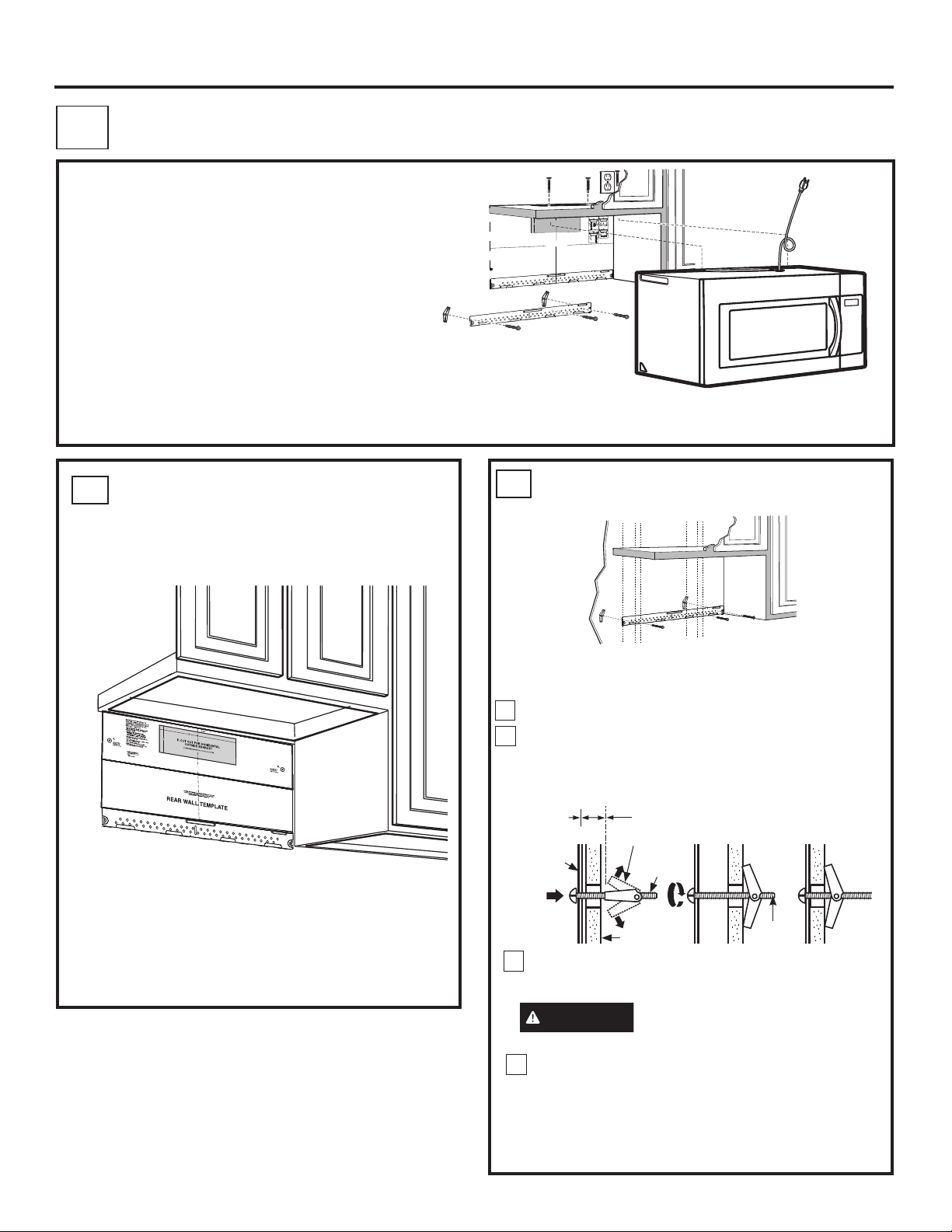
C1. Prepare Rear Wall
C2. Attach Mounting Plate to Wall
C3. Prepare Top Cabinet
C4. Adjust Blower
C5. Mount The Oven
PREPARING THE REAR WALL
C1
FOR OUTSIDE BACK EXHAUST
You need to cut an opening in the rear wall for
outside exhaust.
(Horizontal Duct)
3/8" TO EDGE
OPTION 2
STEP 1:
Installer uses bracket to make 2 marks. First
DISCHARGE INTO HOUSE STRUCTURE
C
mark is made by using the stampled slot in bracket.
Second mark is made on the ouside edge of bracket.
Horizontal line
Make a mark
STEP 4:
Make a mark here, along
here,
inside bottom of the
even with
stamped slot provided.
bottom of
stamped
slot
STEP 2:
Installer moves bracket to the other side of
the cabinets and makes 2 more marks. Marks are the
same as STEP 1, just opposite side.
Make a
mark here,
Make a mark here, along
even with
inside bottom of the
bottom of
stamped slot provided
stamped
(same as Step 1).
slot
NOTES:
- 13” Max Cabinet Depth
- 15” deep cabinets require additional steps using
an additional installation kit: JX36BUMP
C
A
C
A
outlet.
1. Use a level to check that the template is positioned
accurately.
2. Locate and mark at least one stud on the left or
right side of the centerline.
NOTE:
screw mounted firmly in a stud to support the weight
of the microwave. Mark two additional, evenly spaced
locations for the supplied toggle bolts.
3. Drill holes in the marked locations. Where there is
a stud, drill a 3/16" hole for wood screws. For holes
that do not line up with a stud, drill 5/8" holes for
toggle bolts.
NOTE::
AT THIS TIME.
4. Remove the template from the rear wall.
5. Review the Installation Instruction book for your
installation situation.
Darle vuelta a la hoja para consultar la
versión en Español.
Locate and mark holes to align with holes in the
mounting plate.
IMPORTANT:
LOCATE AT LEAST ONE STUD ON EITHER SIDE OF
THE CENTERLINE.
MARK THE LOCATION FOR 2 ADDITIONAL, EVENLY
SPACED TOGGLE BOLTS IN THE MOUNTING PLATE
AREA.
Trim the rear wall template along the dotted line.
B
B
C2
CUT HOLE THROUGH REAR WALL FOR EXHAUST ADAPTOR
It is important to use at least one wood
DO NOT INSTALL THE MOUNTING PLATE
CAUTION - IF EXHAUST ADAPTOR IS POSITIONED OUTSIDE
RECOMMENDED DIMENSION, GREASE-LADEN AIR WILL
30” MINIMUM WIDTH REQUIRED
REAR WALL TEMPLATE
D
D
ATTACH THE MOUNTING
12"
OPTION 1
NOTE: IT IS VERY IMPORTANT TO
READ AND FOLLOW THE DIRECTIONS
IN THE INSTALLATION INSTRUCTIONS
F. CUT OUT FOR HORIZONTAL
BEFORE PROCEEDING WITH THIS
REAR WALL TEMPLATE.
4"
OUTSIDE EXHAUST
This Rear Wall Template serves to position the bottom
mounting plate and to locate the horizontal exhaust
PLATE TO THE WALL
B
D
C
A
• Read the instructions on the REAR WALL
TEMPLATE.
• Tape it to the rear wall, lining up with the holes
previously drilled for holes A and B in the
mounting plate.
• Cut the opening, following the instructions of the
REAR WALL TEMPLATE.
A
C
D
B
Attach the plate to the wall using toggle bolts and wood
screw. At least one wood screw must be used to attach
the plate to a wall stud.
Remove the toggle wings from the bolts.
1
Insert the bolts into the mounting plate through
2
the holes designated to go into drywall and reattach
the toggle wings to 3⁄4″ onto each bolt.
To use toggle bolts:
Spacing for Toggles More
Than Wall Thickness
Mounting
Plate
Insert the toggle wings into the holes in the wall
3
to mount the plate and place the mounting plate
against the wall.
CAUTION
mounting plate and the wall.
4
Tighten all bolts. Pull the plate away from the wall
to help tighten the bolts.
Toggle Wings
Toggle
Bolt
Wall
Bolt
End
Be careful to avoid pinching
fingers between the back of the
20 31-7000132 Rev. 0
Page 21
Installation Instructions
C3.
USE TOP CABINET TEMPLATE
FOR
PREPARATION OF TOP
CABINET
You need to drill holes for the top support screws and
a hole large enough for the power cord to fit through.
B
D
C
A
• Read the instructions on the TOP CABINET
TEMPLATE.
• Tape it underneath the top cabinet.
• Drill the holes, following the instructions on the
TOP CABINET TEMPLATE.
CAUTION
drilling holes in the cabinet bottom.
Wear safety goggles when
C4.
ADAPTING BLOWER FOR
OUTSIDE BACK EXHAUST
Remove and save the two screws that hold the
1
blower plate in place. Slide blower plate from
under its retaining flange. Remove the cover
plate installed on the back. Remove and save
screws that hold blower unit to the oven
Retaining
Flange
Carefully pull out the blower unit. The wires
2
will extend far enough to allow you to adjust
the blower unit.
BEFORE: Fan Blade
Openings Facing Up
Blower
Plate
Back of
Oven
Rotate blower unit counterclockwise 180°.
3
Before Rotation After Rotation
Back of
Oven
Roll the blower unit 90° so that fan blade
4
openings are facing out the back of the
oven.
Before Rolling
Back of
Oven
After Rolling
Back of
Oven
Back of
Oven
31-7000132 Rev. 0 21
Page 22
Installation Instructions
Locate the two “knockout” plates, on the rear
5
oven panel, near the top of the oven.
Using tin snips, carefully cut the web area from
the two holes side-by-side (that secure the
knockouts to the oven). Cut all four webs on both
rear knockouts; this will allow the ventilation fan
airflow to exhaust out the rear of the oven.
Place the blower unit back into the opening.
AFTER: Fan
Blade Openings
Facing Back
CAUTION
edges from the openings after removing the
knockout plates.
Oven Rear Panel
6
CAUTION
Be sure to trim the sharp
Snip all 4 webs
on each knockout
panel and remove
the metal
knockouts for rear
airflow.
Do not pull or stretch
the blower unit wiring. Make sure the
wires are not pinched.
NOTE: The blower unit exhaust openings
should match exhaust openings on rear of oven.
C5.
FOR EASIER INSTALLATION AND PERSONAL
SAFETY, WE RECOMMEND THAT TWO PEOPLE
INSTALL THIS OVEN.
MOUNT THE OVEN
IMPORTANT: Do not grip or use handle
during installation.
NOTE: If your cabinet is metal, use the nylon
grommet around the power cord hole to prevent
cutting of the cord.
NOTE: We recommend using filler blocks if the
cabinet front hangs below the cabinet bottom shelf.
IMPORTANT: If filler blocks are not
used, case damage may occur from over
tightening screws.
NOTE: When mounting the microwave, thread
power cord through hole in bottom of top cabinet.
Keep it tight throughout Steps 1–3. Do not pinch
cord or lift microwave oven by pulling cord.
Lift microwave, tilt it forward, and hook slots
1
at back bottom edge onto four lower tabs of
mounting plate.
Power Cord
Replace the blower plate in the same
7
position as before and replace the screws for
the blower plate and blower motor.Attach the
cover on the blower plate with screw.
Cover Plate
Rotate front of microwave oven up against
2
Blower
Plate
Screws
Blower Plate
Back of Oven
Blower Motor Screws
cabinet bottom.
22 31-7000132 Rev. 0
Page 23
Installation Instructions
Cabinet Front
Cabinet Bottom Shelf
Filler Block
Equivalent
to Depth
of Cabinet
Recess
Self-Aligning Screw
Oven Top
3
Attach the oven to the top cabinet by inserting
2 self-aligning screws through outer top cabinet
holes. Turn two full turns on each screw. Be
sure to keep power cord tight. Be careful not
to pinch the cord, especially when mounting
flush to bottom of cabinet.
4
Tighten the two screws to the top of the oven
completely. (While tightening screws, hold
the oven in place against the wall and the top
cabinet.)
5
Install grease filters. See the Owner’s Manual
packed with the oven.
31-7000132 Rev. 0 23
Page 24

Installation Instructions
BEFORE YOU USE YOUR MICROWAVE
Make sure the microwave oven has been
1.
installed according to instructions.
Remove all packing material from the
2.
microwave oven.
Install turntable and ring in cavity.
3.
Read the Owner’s Manual.
6.
KEEP INSTALLATION INSTRUCTIONS
7.
FOR THE LOCAL INSPECTOR’S USE.
Replace house fuse or turn breaker back on.
4.
Plug power cord into a dedicated 15- to
5.
20-amp electrical outlet.
Ensure proper
ground exists
before use
Printed in China
24 31-7000132 Rev. 0
Page 25

Instructions
Four à micro-ondes
d’installation
AVANT DE COMMENCER
Veuillez lire toutes ces instructions attentivement.
•
IMPORTANT – Conservez ces
instructions à l’usage de l’inspecteur local.
•
IMPORTANT – Observez tous les codes
et règlements en vigueur.
• Note à l’installateur – Assurez-vous de
laisser ces instructions au consommateur.
à hotte intégrée
• Note au consommateur – Conservez ces
instructions pour référence ultérieure.
• Niveau de compétence – L’installation de cet
électroménager exige des compétences de base en
mécanique et électricité.
• L’exactitude de l’installation est la responsabilité de l’installateur.
• La garantie ne couvre pas les défectuosités du produit
causées par une installation inadéquate.
LISEZ ATTENTIVEMENT
CONSERVEZ CES INSTRUCTIONS
31-7000132 Rev. 0 07-20 GEA
Page 26
Instructions d’installation
DANGER
Ce symbole représente une alerte de sécurité. Ce symbole vous avise de dangers potentiels pouvant causer, à vous-même
ou autrui, des blessures graves ou fatales. Tous les messages de sécurité seront précédés du symbole d’alerte de sécurité ainsi
que des mots « DANGER », « AVERTISSEMENT » ou « ATTENTION ». Ces mots se définissent comme suit.
Signale une situation qui présente un danger imminent et qui, si elle n’est pas évitée, entraînera des
blessures graves, voire fatales.
AVERTISSEMENT
ATTENTION
Signale une situation qui présente un danger imminent et qui, si elle n’est pas évitée, peut entraîner des
blessures graves, voire fatales.
Signale une situation qui présente un danger imminent et qui, si elle n’est pas évitée, peut entraîner des
blessures légères ou modérément graves.
INSTRUCTIONS DE SÉCURITÉ IMPORTANTES
Un électricien agréé doit vérifier la continuité de la mise
à la terre de la prise murale avant l’installation pour
confirmer que la boîte de la prise est correctement mise
à la terre. Si la prise murale n’est pas correctement mise
à la terre ou si elle ne satisfait pas les EXIGENCES
ÉLECTRIQUES prescrites dans ce manuel, un électricien
agréé doit corriger toute insuffisance.
AVERTISSEMENT
Risque de choc
électrique. Peut
causer une blessure
ou la mort : Retirez
le fusible domestique
ou déclenchez le
disjoncteur avant de
commencer l’installation
afin d’éviter une
décharge électrique
grave ou fatale.
AVERTISSEMENT
Risque de choc
électrique. Peut causer
Assurez-vous
d’une mise à la
terre correcte
avant toute
utilisation
une blessure ou la mort
: Cet appareil doit être
correctement mis à la
terre afin de prévenir
une décharge électrique
grave ou fatale.
RISQUE DE CHOC ÉLECTRIQUE
AVERTISSEMENT
mort : En aucun cas, VOUS NE DEVEZ couper, déformer
ni retirer une broche quelconque de la fiche du cordon
d’alimentation. N’utilisez pas un cordon de rallonge. Le
non-respect de cette règle peut causer un incendie.
Peut causer une blessure ou la
EXIGENCES ÉLECTRIQUES
Les caractéristiques électriques du produit sont 120 volts
CA, 60 hertz, 13 ampères et 1,5 kilowatts. Ce produit
doit être raccordé à un circuit d’alimentation de tension
et de fréquence appropriées. Le calibre des fils doit être
conforme au Code national de l’électricité ou au code local
en vigueur pour ce nombre de kilowatts. La fiche du cordon
électrique doit être branchée dans une prise simple avec
mise à la terre qui est connectée à un circuit de dérivation
dédié de 15 à 20 ampères. La boîte de sortie de la prise
doit être située dans l’armoire au-dessus du four à microondes. La boîte de sortie et le circuit de la prise doivent
être installés par un électricien agréé et satisfaire le code
national de l’électricité ou le code local en vigueur.
POUR VOTRE SÉCURITÉ:
AVERTISSEMENT
la surface de montage doit pouvoir supporter la charge de
l’armoire, le poids de 63 à 85 lb (26 à 39 kg) du produit et les
charges du four qui peuvent atteindre jusqu’à 50 lb (23 kg),
pour un poids total de 113 à 135 lb (51 à 61 kg).
Pour votre sécurité personnelle,
Le cordon électrique de cet appareil est muni d’une
fiche à trois broches (mise à la terre) correspondant
à une prise murale à trois trous standard (mise à la
terre) afin de réduire le risque de choc électrique
depuis l’appareil.
Si l’on est en présence d’une prise à deux trous,
elle doit être remplacée par une prise à trois trous
correctement mise à la terre, installée par un
électricien agréé.
AVERTISSEMENT
personnelle, ce produit ne peut pas être installé dans une
disposition d’armoires en îlot ou péninsule. Il doit être monté
à la fois dans une armoire supérieure ET sur un mur.
AVERTISSEMENT
blessure (au dos ou autrement en raison du poids excessif
du four à micro-ondes) ou de dommage à la propriété,
deux personnes sont nécessaires pour installer le produit.
Pour votre sécurité
Afin de prévenir le risque de
2 31-7000132 Rev. 0
Page 27

Instructions d’installation
ÉVACUATION DE LA HOTTE
REMARQUE : Lisez les prochaines deux pages seulement si vous prévoyez évacuer votre hotte vers l’extérieur. Si vous prévoyez
recirculer l’air dans la pièce, allez à la page 11. Votre four à micro-ondes est équipé d’un dispositif d’orientation du ventilateur destiné à
recirculer l’air dans la pièce.
ÉVACUATION EXTÉRIEURE PAR LE HAUT (EXEMPLE SEULEMENT)
Le tableau suivant fournit un exemple d’une installation de conduits.
PIÈCES DE CONDUIT
Évent de toit 24 pi X (1) = 24 pi
12 pi Conduit droit
(rond 6 po)
Adaptateur
de transition
rectangulaire-à-rond*
Les longueurs équivalentes des pièces de conduit sont basées sur des tests
réels et ils représentent les exigences nécessaires à une ventilation efficace
pour toute hotte.
LONGUEUR
ÉQUIVALENTE
12 pi X (1) = 12 pi
5 pi X (1) = 5 pi
QUANTITÉ
X
UTILISÉE
Longueur totale =
* IMPORTANT : Si un adaptateur de transition rectangulaire-à-rond est utilisé, les coins inférieurs du registre
devront être coupés sur mesure à l’aide d’une cisaille afin d’assurer le libre mouvement du registre.
ÉVACUATION EXTÉRIEURE PAR L’ARRIÈRE (EXEMPLE SEULEMENT)
Le tableau suivant fournit un exemple d’une installation de conduits.
= LONGUEUR
41 pi
PIÈCES DE CONDUIT
Évent mural 40 pi X (1) = 40 pi
3 pi Conduit droit (3 ¼
x 10 po rectangulaire)
Coude 90° 10 pi X (2) = 20 pi
Les longueurs équivalentes des pièces de conduit sont basées sur des tests réels et
ils représentent les exigences nécessaires à une ventilation efficace pour toute hotte.
LONGUEUR
ÉQUIVALENTE
3 pi X (1) = 3 pi
QUANTITÉ
X
UTILISÉE
= LONGUEUR
Longueur totale =
63 pi
REMARQUE : Pour l’évacuation par l’arrière, il faut veiller à aligner le conduit sur l’espace entre les
montants, ou encore le mur doit être préparé au moment de sa construction en laissant suffisamment
d’espace entre les montants pour faire place à l’évacuation.
31-7000132 Rev. 0 3
Page 28

Instructions d’installation
REMARQUE : Si vous devez installer des conduits, prenez
note que la longueur totale des conduits (rectangulaires de 3
1/4 x 10 po ou ronds de 6 po) ne doit pas dépasser 140 pieds
équivalents.
L’évacuation extérieure exige un CONDUIT D’ÉVACUATION
POUR HOTTE. Lisez ce qui suit attentivement.
REMARQUE : Il est important que l’évacuation soit installée
selon le trajet le plus direct avec le moins de coudes possible.
Cela assure une évacuation libre qui prévient les obstructions.
Assurez-vous aussi que les registres pivotent librement et que
rien ne bloque les conduits.
Connexion de la hotte :
La hotte a été conçue pour se connecter à un conduit
rectangulaire standard de 3 1/4 x 10 po.
Si un conduit rond est requis, vous devez utiliser un adaptateur
de transition rectangulaire-à-rond. N’utilisez pas un conduit de
moins de 6 po de diamètre
PIÈCES DE CONDUIT
Adaptateur
de transition
rectangulaire-à-rond*
LONGUEUR
ÉQUIVALENTE
5 pi X (____) = ____ pi
Longueur maximale du conduit :
Pour obtenir une circulation d’air satisfaisante, la longueur
totale des conduits (rectangulaires de 3 1/4 x 10 po ou ronds
de 6 po) ne doit pas dépasser 140 pieds équivalents.
Les coudes, les transitions, les évents muraux et de toit, etc.,
présentent une résistance supplémentaire au flux d’air et sont
équivalents à une section de conduit droit plus longue que
leur mesure réelle. Lors du calcule de la longueur totale des
conduits, additionnez les longueurs équivalentes de toutes
les transitions et les adaptateurs plus la longueur de tous
les conduits droits. Le tableau ci-dessous indique comment
calculer la longueur équivalente totale des conduits à partir de
la longueur équivalente approximative de certains éléments de
conduit typiques.
X QUANTITÉ UTILISÉE = LONGUEUR
Évent mural 40 pi X (____) = ____ pi
Coude 90° 10 pi X (____) = ____ pi
Coude 45° 5 pi X (____) = ____ pi
Coude 90° 25 pi X (____) = ____ pi
Coude 45° 5 pi X (____) = ____ pi
Évent de toit 24 pi X (____) = ____ pi
3 pi Conduit droit
(3 1/4 x 10 po
rectangulaire)
1 pi X (____) = ____ pi
Longueur de conduits totale = ____ pi
* IMPORTANT : Si l’on utilise un adaptateur
de transition rectangulaire à rond, les coins
inférieurs du registre devront être coupés sur
mesure à l’aide d’une cisaille afin d’assurer le
libre mouvement du registre.
Les longueurs équivalentes des pièces de conduit sont basées sur
des tests réels et ils représentent les exigences nécessaires à une
ventilation efficace pour toute hotte.
4 31-7000132 Rev. 0
Page 29

Instructions d’installation
DOMMAGES CAUSÉS PAR LE TRANSPORT
• Si le produit est endommagé par le transport, retournezle au magasin de votre achat pour réparation ou
remplacement.
• Si le produit est endommagé par le client, la réparation ou
le remplacement sont sous sa responsabilité.
• Si le produit est endommagé par l’installateur (autre que
le client), la réparation ou le remplacement doit faire l’objet
d’une entente entre celui-ci et le client.
PIÈCES INCLUSES
TROUSSE DE QUINCAILLERIE
Pièce Quantité
Vis à bois (1/4 x 2”) 2
Boulons à ailettes (et écrou
à oreilles) (3/16 x 3”)
Vis de mécanique
autocentreuses (1/4” – 28
x 3 ¼”)
Passe-fils en nylon (pour
armoires métalliques)
Vis taraudeuses (pour fixer
le connecteur de conduit
du registre)
2
2
1
3
PIÈCES SUPPLÉMENTAIRES
Pièce Quantité
Gabarit pour
armoire
supérieure
Gabarit pour mur
arrière
Instructions
d’installation
Filtre à graisse
emballé
séparément
Plaque de
montage (pour
supporter le four
à micro-ondes)
Plaque de
recouvrement
(pour la
ventilation de la
pièce)
1
1
1
2
1
1
Une bride pour cordon
électrique et une vis de
montage de couleur foncée
(pour fixer le cordon
électrique)
Vous trouverez la quincaillerie d’installation dans un paquet
qui accompagne l’appareil. Assurez-vous d’obtenir toutes
ces pièces.
REMARQUE : Certaines pièces supplémentaires sont
incluses.
31-7000132 Rev. 0 5
1
Page 30
Instructions d’installation
OUTILS DONT VOUS AUREZ BESOIN
Tournevis
cruciformes nos
1 et 2
Cisaille (pour couper le
registre si nécessaire)
Gants
Lunettes de
sécurité
Crayon
Ciseaux (pour découper
le gabarit si nécessaire)
Scie (sauteuse, cloche ou à
guichet)
Niveau
Règle ou ruban à mesurer et objet à
bord rectiligne
Perceuse électrique avec foret
3/16, 7/16, 1/2 et 5/8 po
Localisateur
de montants
Marteau (facultatif)
Équerre (facultatif)
Filler blocks or scrap
wood pieces, if needed
for top cabinet spacing
(used on recessed
bottom cabinet
installations only)
Ruban à conduits et
ruban-cache
ESPACE DE MONTAGE
*13 po max
16-1/2 po
30 po
2 po
66 po ou
plus depuis
le plancher
jusqu’au dessus
du four
30 po
min
REMARQUES :
• L’espace entre les armoires doit être de 30 po de large et
exempt d’obstructions.
• Ce four est destiné à une installation au-dessus de
cuisinières mesurant jusqu’à 36 po de large.
Le bord inférieur
de l’armoire doit
se situer à 30
po ou plus de
la surface de
Dosseret
cuisson
• Si l’espace entre les armoires est supérieur à 30 po,
on peut utiliser la trousse de panneau de remplissage
pour combler l’espace entre le four à micro-ondes et les
armoires. Votre manuel d’utilisation contient le numéro de la
trousse qui convient à votre modèle.
• Si votre four sera ventilé à l’extérieur, voyez la section
Évacuation de la hotte pour la préparation du conduit
d’évacuation.
• Lorsque vous installez le four sous une armoire dont la
face inférieure est lisse et plate, suivez attentivement
les instructions qui figurent sur le gabarit de l’armoire
supérieure concernant le dégagement pour le cordon
d’alimentation.
• * 13 po max. pour une installation standard, une profondeur
d’armoire de 15 po nécessite des étapes supplémentaires
en utilisant la trousse d’installation supplémentaire
JX15BUMPWW/BB.
• Pour les modèles avec évents dans le haut : Ne laissez pas
les armoires ni d’autres objets bloquer l’air qui s’échappe de
l’évent.
• Les fours à micro-ondes avec hotte intégrée de marque Café
doivent être installés avec des cuisinières Café seulement.
Une installation au-dessus de n’importe quelle autre cuisinière
peut générer des températures de surface qui causent des
brûlures.
• Tous les autres fours à micro-ondes ne doivent pas être
installés au-dessus de tables de cuisson ou de cuisinières
dont les BTU combinés sont supérieurs à 60 000.
6 31-7000132 Rev. 0
Page 31

Instructions d’installation
MISE EN PLACE DE LA PLAQUE DE MONTAGE
1
RETRAIT DU FOUR À MICRO-
A
.
ONDES DE SON EMBALLAGE
Retirez les instructions d’installation, les filtres, le
1
plateau de verre, la plaque de montage et le petit sac
de quincaillerie. Ne retirez pas la mousse qui protège le
devant du four.
Repliez les 4 rabats de la boîte contre ses côtés.
2
Ensuite, roulez avec soin le four et sa boîte pour qu’il
repose sur son dessus. Le four doit demeurer dans la
mousse.
Boîte
Mousse
3
Tirez la boîte vers le haut pour la dégager du four.
4
Remettez le four à l’endroit. Retirez et jetez
proprement les sacs de plastique et l’emballage de
mousse.
B
.
REPÉRER LES MONTANTS
MURAUX
Montants
muraux
Centre
1
Repérez les montants à l’aide d’une des
méthodes suivantes :
A. Détecteur de montant – Un dispositif
magnétique qui localise les clous.
OU
B. Utilisez un marteau pour tapoter légèrement à
travers la surface de montage pour trouver une
résonance solide. Cela indiquera la présence
d’un montant.
Après le repérage des montants, localisez leur
2
centre en sondant le mur à l’aide d’un petit clou
pour trouver les bords du montant. Tracez ensuite
une marque à mi-chemin entre les bords. Le
centre de tout montant adjacent devrait se trouver
à 16 ou 24 po de cette marque.
3
Tracez une ligne verticale au centre des
montants.
LE FOUR À MICRO-ONDES DOIT ÊTRE FIXÉ À
AU MOINS UN MONTANT MURAL.
31-7000132 Rev. 0 7
Page 32

Installation Instructions
DÉTERMINATION DE LA POSITION DE LA PLAQUE DE MONTAGE
C
SOUS L’ARMOIRE
Position de la plaque sous une armoire
à fond plat
Tracez une ligne verticale sur le mur au centre
de l’espace de 30 po. Avec du ruban, fixez le
gabarit pour mur arrière sur le mur en prenant soin
d’aligner la ligne de centre et de toucher le bas de
l’armoire.
Position de la plaque sous une
armoire en surplomb frontal et dont le
bas est en retrait
Tracez une ligne sur
le mur arrière à égalité
avec la profondeur du
surplomb frontal
30 po à la table
de cuisson
Position de la plaque sous une armoire
dont le bas est encadré et en retrait
30 po à la table de cuisson
Tracez une ligne verticale sur le mur au centre de
l’espace de 30 po.
Avec du ruban, fixez le gabarit pour mur arrière sur
le mur en prenant soin d’aligner la ligne de centre
et de toucher le cadre du bas de l’armoire.
Votre armoire peut comporter une garniture décorative qui
gêne l’installation du four à micro-ondes. Retirez la garniture
décorative pour installer le four correctement et le mettre de
niveau.
LE FOUR À MICRO-ONDES DOIT ÊTRE DE NIVEAU
Utilisez un niveau pour vérifier que le bas de l’armoire est
bien de niveau.
Si l’armoire ne présente qu’un surplomb frontal sans cadre
sur l’arrière ou les côtés, installez la plaque de montage vers
le bas à la même distance que la profondeur du surplomb.
Cela maintiendra le four à micro-ondes de niveau
Mesurez la profondeur intérieure du surplomb frontal.
1
Tracez une ligne horizontale sur le mur arrière à la même
2
distance (sous le bas de l’armoire) que la profondeur
intérieure du surplomb frontal.
Pour ce type d’installation avec surplomb frontal
3
seulement, alignez le gabarit pour mur arrière sur cette
ligne horizontale, sans toucher le bas de l’armoire tel que
décrit à l’Étape D.
8 31-7000132 Rev. 0
Page 33
Installation Instructions
MARQUAGE DES TROUS DE MONTAGE
D
OPTION 1 : UTILISATION DU GABARIT EN PAPIER POUR MUR ARRIÈRE
30 po
ATTENTION
OPTION 1
NOTE: IT IS VERY IMPORTANT TO
READ AND FOLLOW THE DIRECTIONS
IN THE INSTALLATION INSTRUCTIONS
BEFORE PROCEEDING WITH THIS
REAR WALL TEMPLATE.
This Rear Wall Template serves to position the bottom
mounting plate and to locate the horizontal exhaust
outlet.
1. Use a level to check that the template is positioned
accurately.
2. Locate and mark at least one stud on the left or
right side of the centerline.
NOTE:It is important to use at least one wood
screw mounted firmly in a stud to support the weight
of the microwave. Mark two additional, evenly spaced
locations for the supplied toggle bolts.
3. Drill holes in the marked locations. Where there is
a stud, drill a 3/16" hole for wood screws. For holes
that do not line up with a stud, drill 5/8" holes for
toggle bolts.
NOTE::DO NOT INSTALL THE MOUNTING PLATE
AT THIS TIME.
4. Remove the template from the rear wall.
5. Review the Installation Instruction book for your
installation situation.
Darle vuelta a la hoja para consultar la
versión en Español.
Locate and mark holes to align with holes in the
mounting plate.
IMPORTANT:
LOCATE AT LEAST ONE STUD ON EITHER SIDE OF
THE CENTERLINE.
MARK THE LOCATION FOR 2 ADDITIONAL, EVENLY
SPACED TOGGLE BOLTS IN THE MOUNTING PLATE
AREA.
Trim the rear wall template along the dotted line.
A
Portez des gants pour éviter des
12"
F. CUT OUT FOR HORIZONTAL
4"
OUTSIDE EXHAUST
CUT HOLE THROUGH REAR WALL FOR EXHAUST ADAPTOR
CAUTION - IF EXHAUST ADAPTOR IS POSITIONED OUTSIDE
RECOMMENDED DIMENSION, GREASE-LADEN AIR WILL
30” MINIMUM WIDTH REQUIRED
REAR WALL TEMPLATE
C
coupures aux doigts sur les bords coupants.
AVERTISSEMENT
causer une blessure ou la mort. Veillez à ne pas percer
dans le câblage électrique à l’intérieur des murs ou des
armoires.
Ce gabarit pour mur arrière sert à situer les trous de montage
pour la plaque de montage inférieure et la sortie d’évacuation
horizontale.
1. Vérifiez avec un niveau que le gabarit est placé avec
précision.
2. Repérez et marquez la position d’au moins un montant sur
les côté gauche ou droit de la ligne de centre.
REMARQUE : Il est important d’utiliser au moins une vis à
bois vissée solidement dans un montant afin de supporter le
poids du four à micro-ondes.
Risque de choc électrique. Peut
3/8" TO EDGE
DISCHARGE INTO HOUSE STRUCTURE
C
Locate and mark holes to align with holes in the
mounting plate.
IMPORTANT:
LOCATE AT LEAST ONE STUD ON EITHER SIDE OF
THE CENTERLINE.
MARK THE LOCATION FOR 2 ADDITIONAL, EVENLY
SPACED TOGGLE BOLTS IN THE MOUNTING PLATE
AREA.
OPTION 2
NOTE: Refer to step C “DETERMINING MOUNTING PLATE LOCATION UNDER YOUR CABINET on page 10 for aligning instructions.
STEP 1: Installer uses bracket to make 2 marks. First
STEP 3: Installer uses a level to draw a horizontal line
mark is made by using the stampled slot in bracket.
that connects the two marks made with the stamped
Second mark is made on the ouside edge of bracket.
slot in the bracket.
Horizontal line
Make a mark
Make a mark here, along
here,
inside bottom of the
STEP 4: Installer uses marks to install bracket in
even with
stamped slot provided.
bottom of
correct position. The bracket is to be installed per
stamped
standard requirements (at least one wood screw
slot
mounted in a stud, two additional evenly spaced
locations for toggle bolts). Mark hole location A,B, C and
D by placing the mounting bracket on the wall as shown
in the picture. Hole C and or D must be in a WALL STUD.
STEP 2: Installer moves bracket to the other side of
the cabinets and makes 2 more marks. Marks are the
same as STEP 1, just opposite side.
Mark hole locations for A, B, C, and D.
B
Place bracket within the lines created in previous steps.
Make a
mark here,
Make a mark here, along
STEP 5: Set mounting bracket aside and drill holes at
even with
inside bottom of the
bottom of
all marked locations. If there is a stud, drill a 3/16” hole
stamped slot provided
stamped
for wood screws. For holes that do not line up with a
(same as Step 1).
slot
stud, drill a 5/8” hole for a toggle bolt.
NOTES:
- 13” Max Cabinet Depth
- 15” deep cabinets require additional steps using
an additional installation kit: JX15BUMP
B
ACD
3. Marquez la position des trous sur le mur à l’aide du gabarit
aux trous A et B. Marquez au moins une position de trou
dans la zone C qui s’aligne sur la position d’un montant. Il
faut un minimum de trois trous pour le montage.
4. Percez les trous aux endroits marqués. À l’endroit du
montant, percez un trou de 3/16 po pour les vis à bois.
Pour les trous qui ne s’alignent pas sur le montant, percez
des trous 5/8 po pour boulons à ailettes.
REMARQUE : N’INSTALLEZ PAS LA PLAQUE DE
MONTAGE POUR LE MOMENT
5. Retirez le gabarit du mur arrière.
31-7000132 Rev. 0 9
Page 34

Installation Instructions
A
C
B
MARQUAGE DES TROUS DE MONTAGE
D
OPTION 2 : UTILISATION D’UN SUPPORT MÉTALLIQUE COMME GABARIT
REMARQUE : Reportez-vous à l’étape C DÉTERMINATION DE LA POSITION DE LA PLAQUE DE MONTAGE SOUS L’ARMOIRE de la page 8
pour les instructions d’alignement
ÉTAPE 1: Tracez une ligne verticale sur le mur au centre
de l’espace de 30 po.
ÉTAPE 2: Utilisez le support pour tracer deux (2)
marques. La première marque est tracée en utilisant la fente
estampée du support. La deuxième marque est tracée sur le
bord extérieur du support.
ÉTAPE 4: Utilisez un niveau pour tracer une ligne
horizontale qui relie les deux marques faites avec la fente
estampée du support.
Ligne horizontale
ÉTAPE 5: Placez le support de montage sur le mur
comme illustré. Tracez des cercles sur le mur aux trous A et
B. Tracez au moins un cercle dans la zone C. Au moins un
cercle DOIT s’aligner sur un montant mural.
Marquez la position des trous
A et B et celui de la zone C.
Tracer une
marque ici sur le
bord extérieur du
support
Tracer une marque ici le long
du bas intérieur de la fente
estampée
ÉTAPE 3: Déplacez le support sur l’autre côté de
l’armoire et tracez deux (2) autres marques. Les marques
sont identiques à L’ÉTAPE 2, juste du côté opposé.
Tracer une marque ici le
long du bas intérieur de
la fente estampée (même
qu’à l’Étape 1).
Tracer une
marque ici sur le
bord extérieur du
support
Placez le support à l’intérieur des lignes tracées aux étapes précédentes
ÉTAPE 6: Mettez le support de montage de côté et
percez les trous aux endroits marqués. À l’endroit du
montant, perces un trou de 3/16 po pour les vis à bois. Pour
les trous qui ne s’alignent pas sur le montant, percez des
trous de 5/8 po pour boulons à ailettes.
10 31-7000132 Rev. 0
Page 35

Installation Instructions
2
Ce four à micro-ondes est conçu pour s’adapter aux trois types
d’évacuation suivants :
A. Recirculation (conduits non évacués vers l’extérieur)
B. Évacuation vers l’extérieur par le haut (conduit vertical)
C. Évacuation vers l’extérieur par l’arrière
(conduit horizontal)
A
TYPES D’INSTALLATION
RECIRCULATION (CONDUITS
NON ÉVACUÉS VERS
L’EXTÉRIEUR)
(Choisissez A, B ou C)
REMARQUE : Sélectionnez le type d’évacuation requis pour
votre installation et exécutez les étapes de cette section.
B
ÉVACUATION VERS
L’EXTÉRIEUR PAR LE HAUT
(CONDUIT VERTICAL)
Adaptateur en place
pour l’évacuation
extérieure par le haut
Voir la page 12
Une trousse de filtre à charbon en option est nécessaire pour
une évacuation recirculée. (Consultez le manuel d’utilisation
pour le numéro de la trousse.)
C
ÉVACUATION VERS
L’EXTÉRIEUR PAR L’ARRIÈRE
(CONDUIT HORIZONTAL)
Voir la page 20
Voir la page 16
31-7000132 Rev. 0 11
Page 36

Installation Instructions
A
RECIRCULATING (conduits non évacués vers l’extérieur)
SOMMAIRE DE L’INSTALLATION
A1. Fixation de la plaque de montage sur le mur
A2. Préparation de l’armoire supérieure
A3. Vérification de l’orientation du ventilateur
A4. Adaptation du ventilateur du four à micro-ondes
pour la recirculation
A5. Montage du four à micro-ondes
A6. Installation du filtre à charbon
A1
FIXATION DE LA PLAQUE DE
MONTAGE SUR LE MUR
3/8" TO EDGE
OPTION 2
STEP 1:
Installer uses bracket to make 2 marks. First
DISCHARGE INTO HOUSE STRUCTURE
C
mark is made by using the stampled slot in bracket.
Second mark is made on the ouside edge of bracket.
Horizontal line
Make a mark
STEP 4:
Make a mark here, along
here,
inside bottom of the
even with
stamped slot provided.
bottom of
stamped
slot
STEP 2:
Installer moves bracket to the other side of
the cabinets and makes 2 more marks. Marks are the
same as STEP 1, just opposite side.
Make a
mark here,
Make a mark here, along
even with
inside bottom of the
bottom of
stamped slot provided
stamped
(same as Step 1).
slot
NOTES:
- 13” Max Cabinet Depth
- 15” deep cabinets require additional steps using
an additional installation kit: JX36BUMP
C
A
C
A
12"
OPTION 1
NOTE: IT IS VERY IMPORTANT TO
READ AND FOLLOW THE DIRECTIONS
IN THE INSTALLATION INSTRUCTIONS
F. CUT OUT FOR HORIZONTAL
BEFORE PROCEEDING WITH THIS
REAR WALL TEMPLATE.
4"
OUTSIDE EXHAUST
This Rear Wall Template serves to position the bottom
mounting plate and to locate the horizontal exhaust
outlet.
CUT HOLE THROUGH REAR WALL FOR EXHAUST ADAPTOR
1. Use a level to check that the template is positioned
accurately.
2. Locate and mark at least one stud on the left or
right side of the centerline.
NOTE:
It is important to use at least one wood
screw mounted firmly in a stud to support the weight
of the microwave. Mark two additional, evenly spaced
locations for the supplied toggle bolts.
3. Drill holes in the marked locations. Where there is
a stud, drill a 3/16" hole for wood screws. For holes
that do not line up with a stud, drill 5/8" holes for
toggle bolts.
NOTE::
DO NOT INSTALL THE MOUNTING PLATE
AT THIS TIME.
4. Remove the template from the rear wall.
5. Review the Installation Instruction book for your
installation situation.
Darle vuelta a la hoja para consultar la
versión en Español.
CAUTION - IF EXHAUST ADAPTOR IS POSITIONED OUTSIDE
RECOMMENDED DIMENSION, GREASE-LADEN AIR WILL
Locate and mark holes to align with holes in the
mounting plate.
IMPORTANT:
LOCATE AT LEAST ONE STUD ON EITHER SIDE OF
THE CENTERLINE.
MARK THE LOCATION FOR 2 ADDITIONAL, EVENLY
SPACED TOGGLE BOLTS IN THE MOUNTING PLATE
AREA.
Trim the rear wall template along the dotted line.
B
B
30” MINIMUM WIDTH REQUIRED
REAR WALL TEMPLATE
D
D
IMPORTANT: Ne retirez
pas les espaceurs en
carton entre l’écran
thermique et la porte
Placez la plaque de montage contre le mur et
3
insérez les ailettes dans les trous du mur pour
monter la plaque.
ATTENTION
Veillez à ne pas pincer vos
doigts entre l’arrière de la plaque et le mur.
A
D
B
C
Fixez la plaque sur le mur à l’aide de boulons à ailettes
et de vis à bois. Au moins une vis à bois doit être utilisée
pour fixer la plaque sur un montant mural.
Retirez les ailettes des boulons.
1
Insérez les boulons dans la plaque de montage à
2
travers les trous destinés aux cloisons sèches et
remettez les ailettes à 3/4 po sur chaque boulon.
Pour utiliser les boulons à ailettes :
Distance des ailettes
supérieure à l’épaisseur du mur
Ailettes
Plaque de
montage
Boulon à
ailettes
Mur
Extrémité
du boulon
Serrez tous les boulons. Tirez la plaque du mur
4
pour faciliter le serrage des boulons.
A2
UTILISATION DU GABARIT POUR
ARMOIRE SUPÉRIEURE POUR
PRÉPARER CETTE ARMOIRE
Vous devez percer des trous pour les vis du support
supérieur et un trou suffisamment grand pour faire
passer le cordon d’alimentation.
• Lisez les instructions sur le GABARIT POUR
ARMOIRE SUPÉRIEURE.
• Avec du ruban, fixez le gabarit sous l’armoire
supérieure.
• Percez les trous, en suivant les instructions sur le
GABARIT POUR ARMOIRE SUPÉRIEURE.
ATTENTION
pour percer des trous dans le bas de l’armoire.
Portez des lunettes de sécurité
12 31-7000132 Rev. 0
Page 37

Installation Instructions
VÉRIFICATION DE L’ORIENTATION
A3.
DU VENTILATEUR
L’orifice des pales du ventilateur doit faire face
au devant du micro-ondes. Vous devez retirer la
plaque de recouvrement supérieure pour vérifier
l’orientation des pales du ventilateur. Si l’orifice fait
déjà face au devant du micro-ondes, sautez à l’étape
A5. Autrement, continuez à l’Étape A4 pour régler
l’orientation du moteur du ventilateur
4
Roulez le ventilateur de 90° pour que les orifices
des pales soient face au devant du four.
AVANT : Orifices des
pales du ventilateur
vers le haut
A4.
ADAPTATION DU VENTILATEUR
POUR LA RECIRCULATION
REMARQUE : TL’adaptateur d’évacuation avec
registre n’est pas nécessaire pour les modèles à
recirculation. Vous pouvez le conserver pour une
éventuelle utilisation ultérieure.
Retirez et conservez les vis qui fixent la plaque de
1
ventilateur sur le four.
Vis de plaque de ventilateur
Plaque de ventilateur
Arrière du
four
Plaque de
recouvrement
Glissez la plaque de ventilateur depuis le
2
dessous de sa collerette et soulevez-la. Retirez
la plaque de recouvrement installée sur l’arrière.
Retirez et conservez les vis qui fixent le
ventilateur sur le four.
Rouler
APRÈS : Orifices des
pales du ventilateur vers
l’avant
Collerette
Plaque de
ventilateur
Vis de moteur
de ventilateur
Plaque de
recouvrement
Tirez avec soin le ventilateur. Les câbles sont
3
suffisamment longs pour vous permettre de
régler le ventilateur.
31-7000132 Rev. 0 13
Page 38

Installation Instructions
A4.
ADAPTATION DU VENTILATEUR
POUR LA RECIRCULATION (suite)
Remettez le ventilateur dans son logement.
5
Vis de
plaque de
ventilateur
CAUTION
câbles du ventilateur ou de les tendre. Assurezvous que les câbles ne sont pas coincés.
Réinstallez les vis du moteur de ventilateur retirées à
6
l’Étape 2. Glissez la plaque de recouvrement en place sur
l’arrière de l’appareil. Réinstallez la plaque de ventilateur
et les vis retirées à l’Étape 1. Fixez la deuxième plaque de
recouvrement sur la plaque de ventilateur (incluant une vis).
Abstenez-vous de tirer sur les
Plaque de
recouvrement
Plaque de
ventilateur
Arrière du
four
REMARQUE : Lors du
montage du four, faites passer
le cordon d’alimentation à
travers le trou dans le bas de
l’armoire supérieure. Gardezle tendu tout au long des
Étapes 1 à 3. Ne coincez pas
le cordon et ne soulevez pas
le four en tirant ce cordon.
Tournez le devant du
2
four vers le haut contre
le bas de l’armoire.
Soulevez le four,
1
inclinez-le vers l’avant
et accrochez les fentes
du bord inférieur arrière
sur les deux languettes
inférieures de la plaque
de montage.
Vis de moteur de
ventilateur
Plaque de
recouvrement
A5.
MONTAGE DU FOUR À
MICRO-ONDES
POUR FACILITER L’INSTALLATION ET LA SÉCURITÉ
PERSONNELLE, NOUS RECOMMANDONS LA
PARTICIPATION DE DEUX PERSONNES POUR INSTALLER
LE FOUR.
IMPORTANT : N’agrippez ni n’utilisez la poignée pendant
l’installation.
REMARQUE : Si votre armoire est en métal, utilisez le
passe-fils en nylon autour du trou de cordon d’alimentation
afin d’empêcher le cisaillement du cordon.
REMARQUE : Nous recommandons d’utiliser des blocs de
calage si le devant de l’armoire dépasse le dessous de sa
tablette inférieure.
IMPORTANT : L’absence de blocs de calage peut
entraîner l’endommagement du caisson par serrage
excessif des vis.
Devant de l’armoire
Tablette inférieure de l’armoire
Bloc de calage
Équivaut à la
profondeur du retrait
de l’armoire
Vis autocentreuse
Dessus du four
14 31-7000132 Rev. 0
Page 39

Installation Instructions
A4.
MONTAGE DU FOUR À
MICRO-ONDES (suite)
Fixez le four sur l’armoire supérieure en insérant
3
deux (2) vis autocentreuses à travers les trous
extérieurs de l’armoire. Vissez chaque vis de deux
tours complets. Assurez-vous de garder le cordon
d’alimentation tendu. Veillez à ne pas coincer le
cordon, notamment dans le cas d’un montage à
égalité avec le bas de l’armoire.
4
Serrez les deux vis dans le haut du four
complètement. (En serrant les vis, maintenez le four
en place contre le mur et l’armoire supérieure.)
A6.
REMPLACEMENT DU
FILTRE À CHARBON
Si le modèle n’est pas évacué à l’extérieur, l’air sera
recirculée à travers un filtre à charbon jetable qui capte la
fumée et les odeurs.
Le filtre à charbon doit être remplacé lorsqu’il devient sale
ou décoloré (généralement au bout de 6 à 12 mois, selon
l’usage de la hotte). Consultez le manuel d’utilisation pour
le numéro de trousse du filtre.
Remise en place du filtre à charbon :
Ouvrez la porte du four à micro-ondes.
1
Retirez les deux vis dans le haut de la grille. (Vous
2
devrez peut-être ouvrir les portes de l’armoire pour
retirer les vis.)
Glissez la grille vers la gauche et l’avant pour la retirer.
3
Filtre à
charbon
Glissez le vieux filtre vers le bas et l’extérieur pour le
Installez les filtres à graisse. Consultez le
5
manuel d’utilisation qui accompagne le four.
31-7000132 Rev. 0 15
4
sortir.
Retirez le plastique et les autres emballages extérieurs
5
du nouveau filtre et installez celui-ci. S’il est bien
installé, le treillis métallique du filtre doit être visible
depuis l’avant.
Replacez la grille et les 2 vis.
6
Fermez la porte.
7
Insérer le côté treillis du filtre vers le haut
Page 40

Instructions d’installation
B
SOMMAIRE DE L’INSTALLATION
B1. Fixation de la plaque de
B2. Préparation de l’armoire
B3. Vérification de l’orientation
B4. Adaptation pour l’évacuation
B5. Assemblage et installation
B6. Montage du four à
B7. Ajustement de l’adaptateur
B8. Connexion des conduits
ÉVACUATION VERS L’EXTÉRIEUR PAR LE HAUT
(CONDUIT VERTICAL)
montage sur le mur
OPTION 1
NOTE: IT IS VERY IMPORTANT TO
READ AND FOLLOW THE DIRECTIONS
IN THE INSTALLATION INSTRUCTIONS
BEFORE PROCEEDING WITH THIS
REAR WALL TEMPLATE.
supérieure
du ventilateur
à l’extérieur
de l’adaptateur
micro-ondes
d’évacuation
This Rear Wall Template serves to position the bottom
mounting plate and to locate the horizontal exhaust
outlet.
1. Use a level to check that the template is positioned
accurately.
2. Locate and mark at least one stud on the left or
right side of the centerline.
NOTE:
It is important to use at least one wood
screw mounted firmly in a stud to support the weight
of the microwave. Mark two additional, evenly spaced
locations for the supplied toggle bolts.
3. Drill holes in the marked locations. Where there is
a stud, drill a 3/16" hole for wood screws. For holes
that do not line up with a stud, drill 5/8" holes for
toggle bolts.
NOTE::
DO NOT INSTALL THE MOUNTING PLATE
AT THIS TIME.
4. Remove the template from the rear wall.
5. Review the Installation Instruction book for your
installation situation.
Darle vuelta a la hoja para consultar la
versión en Español.
Locate and mark holes to align with holes in the
mounting plate.
IMPORTANT:
LOCATE AT LEAST ONE STUD ON EITHER SIDE OF
THE CENTERLINE.
MARK THE LOCATION FOR 2 ADDITIONAL, EVENLY
SPACED TOGGLE BOLTS IN THE MOUNTING PLATE
AREA.
Trim the rear wall template along the dotted line.
B
D
B
4"
D
3/8" TO EDGE
12"
F. CUT OUT FOR HORIZONTAL
OUTSIDE EXHAUST
CUT HOLE THROUGH REAR WALL FOR EXHAUST ADAPTOR
CAUTION - IF EXHAUST ADAPTOR IS POSITIONED OUTSIDE
RECOMMENDED DIMENSION, GREASE-LADEN AIR WILL
DISCHARGE INTO HOUSE STRUCTURE
30” MINIMUM WIDTH REQUIRED
REAR WALL TEMPLATE
C
C
NOTES:
- 13” Max Cabinet Depth
- 15” deep cabinets require additional steps using
an additional installation kit: JX36BUMP
C
A
STEP 1:
mark is made by using the stampled slot in bracket.
Second mark is made on the ouside edge of bracket.
Make a mark
here,
even with
bottom of
stamped
slot
STEP 2:
the cabinets and makes 2 more marks. Marks are the
same as STEP 1, just opposite side.
Installer uses bracket to make 2 marks. First
Installer moves bracket to the other side of
OPTION 2
Horizontal line
STEP 4:
Make a mark here, along
inside bottom of the
stamped slot provided.
Make a
mark here,
Make a mark here, along
even with
inside bottom of the
bottom of
stamped slot provided
stamped
(same as Step 1).
slot
A
IMPORTANT : Ne retirez pas les
espaceurs en carton entre l’écran
thermique et la porte.
FIXATION DE LA PLAQUE DE
B1
MONTAGE SUR LE MUR
A
D
B
Fixez la plaque sur le mur à l’aide de boulons à ailettes et
de vis à bois. Au moins une vis à bois doit servir à fixer la
plaque à un montant mural.
Retirez les ailettes des boulons.
1
Insérez les boulons dans la plaque de montage à
2
travers les trous destinés aux cloisons sèches et
remettez les ailettes à 3/4 po sur chaque boulon.
C
Pour utiliser les boulons à ailettes :
Distance des ailettes
supérieure à l’épaisseur du mur
Plaque de
montage
Insérez les ailettes dans les trous du mur et placez la
3
plaque de montage contre le mur.
CAUTION
entre l’arrière de la plaque et le mur.
Serrer tous les boulons. Tirez la plaque du mur pour
4
faciliter le serrage des boulons.
Ailettes
Boulon à
ailettes
Mur
Plaque de montage
Extrémité du
boulon
Veillez à ne pas pincer vos doigts
16 31-7000132 Rev. 0
Page 41

Instructions d’installation
UTILISATION DU GABARIT POUR
B2
ARMOIRE SUPÉRIEURE POUR
PRÉPARER CETTE ARMOIRE
Vous devez percer des trous pour les vis du support
supérieur, un trou suffisamment grand pour faire passer le
cordon d’alimentation et un orifice suffisamment grand pour
l’adaptateur d’évacuation.
B
D
• Lisez les instructions sur le GABARIT POUR ARMOIRE
SUPÉRIEURE.
• Avec du ruban, fixez le gabarit sous l’armoire supérieure.
• Percez les trous, en suivant les instructions sur le
GABARIT POUR ARMOIRE SUPÉRIEURE.
CAUTION
pour percer des trous dans le bas de l’armoire.
C
A
Portez des lunettes de sécurité
Glissez la plaque de ventilateur depuis le dessous
2
de sa collerette et soulevez-la. Retirez la plaque
de recouvrement installée sur l’arrière. Retirez et
conservez les vis qui fixent le ventilateur sur le four.
Collerette
Plaque de
ventilateur
Vis de moteur de
ventilateur
Plaque de
recouvrement
Tirez avec soin le ventilateur. Les câbles sont
3
suffisamment longs pour vous permettre de régler le
ventilateur.
Roulez le ventilateur de 90° pour que les orifices des
4
pales soient orientés vers le haut du four.
AVANT : Orifices des
pales du ventilateur
vers le devant
B3.
VÉRIFICATION DE
L’ORIENTATION DU
VENTILATEUR
L’orifice des pales du ventilateur doit pointer vers le haut du
micro-ondes. Si l’orifice pointe déjà vers le haut du microondes, sautez à l’étape B5. Autrement, continuez à l’Étape B4
pour régler l’orientation du moteur du ventilateur.
B4.
ADAPTATION DU VENTILATEUR
POUR UNE ÉVACUATION À
L’EXTÉRIEUR
Retirez le couvercle installé sur la plaque de ventilateur
1
(incluant une vis). Retirez et conservez les vis qui fixent
la plaque de ventilateur sur le four.
Plaque de
Vis de
plaque de
ventilateur
recouvrement
Plaque de ventilateur
Arrière du
four
Vis de moteur de
ventilateur
Plaque de
recouvrement
Rouler
APRÈS : Orifices
des pales du
ventilateur vers
le haut
31-7000132 Rev. 0 17
Page 42

Instructions d’installation
B4.
ADAPTATION DU VENTILATEUR
POUR UNE ÉVACUATION À
L’EXTÉRIEUR (suite)
Remettez le ventilateur dans son logement.
5
CAUTION
câbles du ventilateur ou de les tendre. Assurezvous que les câbles ne sont pas coincés.
Réinstallez les vis du moteur de ventilateur retirées à
6
l’Étape 2. Glissez la plaque de recouvrement en place
sur l’arrière de l’appareil. Réinstallez la plaque de
ventilateur et les vis retirées à l’Étape 1.
Vis de
plaque de
ventilateur
B5.
ASSEMBLAGE ET INSTALLATION
Abstenez-vous de tirer sur les
Plaque de
ventilateur
Arrière du
four
Vis de moteur de
ventilateur
Plaque de
recouvrement
DE L’ADAPTATEUR
Registre
Adaptateur
d’échappement
Plaque de
ventilateur
Arrière
du four
Fixez l’adaptateur d’évacuation sur la plaque de
3
ventilateur à l’aide des deux vis métalliques de couleur
bronze fournies.
Assurez-vous que le registre pivote librement avant
de monter le four.
Vous devrez faire des ajustements pour obtenir le bon
alignement avec le conduit d’évacuation de la maison
une fois le four installé.
B6.
MONTAGE DU FOUR À
MICRO-ONDES
POUR FACILITER L’INSTALLATION ET LA SÉCURITÉ
PERSONNELLE, NOUS RECOMMANDONS LA
PARTICIPATION DE DEUX PERSONNES POUR
INSTALLER LE FOUR.
IMPORTANT : N’agrippez ni n’utilisez la poignée
pendant l’installation.
REMARQUE : Si votre armoire est en métal, utilisez
le passe-fils en nylon autour du trou de cordon
d’alimentation afin d’empêcher le cisaillement du cordon.
REMARQUE : Nous recommandons d’utiliser des blocs
de calage si le devant de l’armoire dépasse le dessous de
sa tablette inférieure.
IMPORTANT : L’absence de blocs de calage peut
entraîner l’endommagement du caisson par serrage
excessif des vis.
REMARQUE : Lors du montage du micro-ondes, faites
passer le cordon d’alimentation à travers le trou dans
le bas de l’armoire supérieure. Gardez-le tendu tout au
long des Étapes 1 à 3. Ne coincez pas le cordon et ne
soulevez pas le four en tirant ce cordon.
1
Soulevez le four, inclinez-le vers l’avant et accrochez
les fentes du bord inférieur arrière sur les quatre
languettes inférieures de la plaque de montage.
Cordon
électrique
Plaque de
recouvrement
REMARQUE : Sur certains modèles, l’adaptateur
d’évacuation et le registre sont déjà assemblés sur le four.
1
Placez le four dans sa position droite, dessus de
l’appareil orienté vers le haut.
REMARQUE : Assurez-vous que les pales du ventilateur
sont visibles et orientées vers le haut.
Insérez les languettes de chaque côté du registre dans
2
les trous de la face arrière intérieure de l’adaptateur.
Tournez le devant du four à micro-ondes vers le haut
2
contre le bas de l’armoire.
18 31-7000132 Rev. 0
Page 43

Instructions d’installation
B6.
MONTAGE DU FOUR À
MICRO-ONDES (suite)
Devant de l’armoire
Tablette inférieure de l’armoire
Bloc de calage
Équivaut à la
profondeur du retrait
de l’armoire
Vis autocentreuse
Dessus du four
Fixez le four sur l’armoire supérieure en insérant
3
deux (2) vis autocentreuses à travers les trous
extérieurs de l’armoire. Vissez chaque vis de deux
tours complets. Assurez-vous de garder le cordon
d’alimentation tendu. Veillez à ne pas coincer le
cordon, notamment dans le cas d’un montage à
égalité avec le bas de l’armoire.
B7.
AJUSTEMENT DE
L’ADAPTATEUR D’ÉVACUATION
Ouvrez l’armoire supérieure et ajustez l’adaptateur
d’évacuation pour le connecter au conduit de la maison.
Registre
Arrière du four
Plaque de
recouvrement
B8.
CONNEXION DES CONDUITS
Conduit de la
maison
Serrez les deux vis dans le haut du four
4
complètement. (En serrant les vis, maintenez le four
en place contre le mur et l’armoire supérieure.)
Installez les filtres à graisse. Consultez le manuel
5
d’utilisation qui accompagne le four.
Prolongez le conduit de la maison vers le bas
1
pour le connecter à l’adaptateur d’évacuation.
Scellez les joints du conduit avec du ruban à
2
conduits.
31-7000132 Rev. 0 19
Page 44

Instructions d’installation
C
ÉVACUATION VERS L’EXTÉRIEUR PAR L’ARRIÈRE
(conduit horizontal)
SOMMAIRE DE L’INSTALLATION
C1. Préparation du mur arrière
C2. Fixation de la plaque de montage sur le mur
C3. Préparation de l’armoire supérieure
C4. Ajustement du ventilateur
C5. Montage du four à micro-ondes
PRÉPARATION DU MUR ARRIÈRE
C1
POUR UNE ÉVACUATION VERS
L’EXTÉRIEUR PAR L’ARRIÈRE
Vous devez découper une ouverture dans le mur arrière
pour l’évacuation extérieure.
3/8" TO EDGE
OPTION 2
STEP 1:
Installer uses bracket to make 2 marks. First
DISCHARGE INTO HOUSE STRUCTURE
C
mark is made by using the stampled slot in bracket.
Second mark is made on the ouside edge of bracket.
Horizontal line
Make a mark
STEP 4:
Make a mark here, along
here,
inside bottom of the
even with
stamped slot provided.
bottom of
stamped
slot
STEP 2:
Installer moves bracket to the other side of
the cabinets and makes 2 more marks. Marks are the
same as STEP 1, just opposite side.
Make a
mark here,
Make a mark here, along
even with
inside bottom of the
bottom of
stamped slot provided
stamped
(same as Step 1).
slot
NOTES:
- 13” Max Cabinet Depth
- 15” deep cabinets require additional steps using
an additional installation kit: JX36BUMP
C
A
C
A
12"
OPTION 1
NOTE: IT IS VERY IMPORTANT TO
READ AND FOLLOW THE DIRECTIONS
IN THE INSTALLATION INSTRUCTIONS
F. CUT OUT FOR HORIZONTAL
BEFORE PROCEEDING WITH THIS
REAR WALL TEMPLATE.
4"
OUTSIDE EXHAUST
This Rear Wall Template serves to position the bottom
mounting plate and to locate the horizontal exhaust
outlet.
CUT HOLE THROUGH REAR WALL FOR EXHAUST ADAPTOR
1. Use a level to check that the template is positioned
accurately.
2. Locate and mark at least one stud on the left or
right side of the centerline.
NOTE:
It is important to use at least one wood
screw mounted firmly in a stud to support the weight
of the microwave. Mark two additional, evenly spaced
locations for the supplied toggle bolts.
3. Drill holes in the marked locations. Where there is
a stud, drill a 3/16" hole for wood screws. For holes
that do not line up with a stud, drill 5/8" holes for
toggle bolts.
NOTE::
DO NOT INSTALL THE MOUNTING PLATE
AT THIS TIME.
4. Remove the template from the rear wall.
5. Review the Installation Instruction book for your
installation situation.
Darle vuelta a la hoja para consultar la
versión en Español.
CAUTION - IF EXHAUST ADAPTOR IS POSITIONED OUTSIDE
RECOMMENDED DIMENSION, GREASE-LADEN AIR WILL
Locate and mark holes to align with holes in the
mounting plate.
IMPORTANT:
LOCATE AT LEAST ONE STUD ON EITHER SIDE OF
THE CENTERLINE.
MARK THE LOCATION FOR 2 ADDITIONAL, EVENLY
SPACED TOGGLE BOLTS IN THE MOUNTING PLATE
AREA.
Trim the rear wall template along the dotted line.
B
B
C2
30” MINIMUM WIDTH REQUIRED
REAR WALL TEMPLATE
D
D
FIXATION DE LA PLAQUE DE
MONTAGE SUR LE MUR
B
D
C
A
• Lisez les instructions sur le GABARIT POUR MUR
ARRIÈRE.
• Avec du ruban, fixez le gabarit sur le mur arrière en
l’alignant sur les trous précédemment percés pour les
trous A et B dans la plaque de montage.
• Découpez l’ouverture en suivant les instructions du
GABARIT POUR MUR ARRIÈRE.
A
C
D
B
Fixez la plaque sur le mur à l’aide de boulons à ailettes et
de vis à bois. Au moins une vis à bois doit servir à fixer la
plaque à un montant mural.
Retirez les ailettes des boulons.
1
Insérez les boulons dans la plaque de montage à
2
travers les trous destinés aux cloisons sèches et
remettez les ailettes à 3/4 po sur chaque boulon.
Pour utiliser les boulons à ailettes :
Distance des ailettes
supérieure à l’épaisseur du mur
Plaque de
montage
Insérez les ailettes dans les trous du mur et placez la
3
plaque de montage contre le mur.
Ailettes
Boulon à
ailettes
Mur
Extrémité du
boulon
CAUTION
Veillez à ne pas pincer vos doigts
entre l’arrière de la plaque et le mur.
Serrer tous les boulons. Tirez la plaque du mur pour
4
faciliter le serrage des boulons.
20 31-7000132 Rev. 0
Page 45

Instructions d’installation
UTILISATION DU GABARIT POUR
C3
ARMOIRE SUPÉRIEURE POUR
PRÉPARER CETTE ARMOIRE
Vous devez percer des trous pour les vis du support
supérieur et un trou suffisamment grand pour faire passer
le cordon d’alimentation.
B
D
• Lisez les instructions sur le GABARIT POUR ARMOIRE
SUPÉRIEURE.
• Avec du ruban, fixez le gabarit sous l’armoire supérieure.
• Percez les trous, en suivant les instructions sur le
GABARIT POUR ARMOIRE SUPÉRIEURE.
C
A
C4.
ADAPTATION DU VENTILATEUR
POUR UNE ÉVACUATION À
L’EXTÉRIEUR PAR L’ARRIÈRE
Retirez et conservez les deux vis qui fixent la plaque
1
de ventilateur en place. Glissez la plaque de ventilateur
depuis le dessous de sa collerette. Retirez la plaque de
recouvrement installée sur l’arrière. Retirez et conservez
les vis qui fixent le ventilateur sur le four.
Collerette
Plaque de
ventilateur
Tirez avec soin le ventilateur. Les câbles sont
2
suffisamment longs pour vous permettre de régler le
ventilateur.
AVANT : Orifices des
pales du ventilateur
vers le haut
CAUTION
pour percer des trous dans le bas de l’armoire.
Portez des lunettes de sécurité
Tournez le ventilateur de 180° dans le sens
3
contraire des aiguilles.
Avant la rotation Après la rotation
Arrière du
four
Roulez le ventilateur de 90° pour que les orifices
4
des pales soient face à l’arrière du four.
Avant le
roulement
Après le
roulement
Arrière du
four
Arrière
du four
Arrière du
four
31-7000132 Rev. 0 21
Arrière du
four
Page 46

Instructions d’installation
Repérez les deux débouchures sur le panneau arrière
5
du four, près du haut du four.
À l’aide d’une cisaille, coupez avec soin la zone des
languettes à partir des deux trous côte à côte (qui
fixent les débouchures sur le four). Coupez toutes les
quatre languettes sur les deux débouchures arrière;
cela permettra la circulation de l’air du ventilateur vers
l’arrière du four.
MONTAGE DU FOUR À
C5
MICRO-ONDES
Remettez le ventilateur dans son logement.
APRÈS :
Orifices des
pales du
ventilateur vers
l’arrière
CAUTION
bords coupants des ouvertures après le retrait
des débouchures.
Panneau arrière du four
Assurez-vous d’adoucir les
Découper les quatre
(4) languettes sur
chaque débouchure
et retirez les
débouchures pour
l’évacuation vers
l’arrière.
6
CAUTION
câbles du ventilateur ou de les tendre. Assurezvous que les câbles ne sont pas coincés.
REMARQUE : Les orifices d’évacuation du
ventilateur doivent correspondre aux orifices
d’évacuation sur l’arrière du four.
Replacez la plaque de ventilateur dans la même
7
position que précédemment et réinstallez les
vis de la plaque de ventilateur et du moteur de
ventilateur. Fixez le couvercle sur la plaque de
ventilateur avec la vis
Abstenez-vous de tirer sur les
POUR FACILITER L’INSTALLATION ET LA SÉCURITÉ
PERSONNELLE, NOUS RECOMMANDONS LA
PARTICIPATION DE DEUX PERSONNES POUR
INSTALLER LE FOUR.
IMPORTANT : N’agrippez ni n’utilisez la poignée
pendant l’installation.
REMARQUE : Si votre armoire est en métal, utilisez
le passe-fils en nylon autour du trou de cordon
d’alimentation afin d’empêcher le cisaillement du cordon.
REMARQUE : Nous recommandons d’utiliser des blocs
de calage si le devant de l’armoire dépasse le dessous de
sa tablette inférieure.
IMPORTANT : L’absence de blocs de calage peut
entraîner l’endommagement du caisson par serrage
excessif des vis.
REMARQUE : Lors du montage du micro-ondes, faites
passer le cordon d’alimentation à travers le trou dans
le bas de l’armoire supérieure. Gardez-le tendu tout au
long des Étapes 1 à 3. Ne coincez pas le cordon et ne
soulevez pas le four en tirant ce cordon.
1
Soulevez le four, inclinez-le vers l’avant et accrochez
les fentes du bord inférieur arrière sur les quatre
languettes inférieures de la plaque de montage.
Cordon
électrique
Plaque de
Vis de
plaque de
ventilateur
recouvrement
Plaque de
ventilateur
Arrière du four
Vis de moteur de
ventilateur
Tournez le devant du four à micro-ondes vers le haut
2
contre le bas de l’armoire.
22 31-7000132 Rev. 0
Page 47

Instructions d’installation
Devant de l’armoire
Tablette inférieure de l’armoire
Bloc de calage
Équivaut à la
profondeur
du retrait de
l’armoire
Vis autocentreuse
Dessus du four
Fixez le four sur l’armoire supérieure en insérant
3
deux (2) vis autocentreuses à travers les trous
extérieurs de l’armoire. Vissez chaque vis de deux
tours complets. Assurez-vous de garder le cordon
d’alimentation tendu. Veillez à ne pas coincer le
cordon, notamment dans le cas d’un montage à
égalité avec le bas de l’armoire.
Serrez les deux vis dans le haut du four
4
complètement. (En serrant les vis, maintenez le four
en place contre le mur et l’armoire supérieure.)
Installez les filtres à graisse. Consultez le manuel
5
d’utilisation qui accompagne le four.
31-7000132 Rev. 0 23
Page 48

Installation Instructions
AVANT D’UTILISER VOTRE FOUR À MICRO-ONDES
Assurez-vous que le four à micro-ondes a été
1.
installé selon les instructions.
Retirez tout le matériel d’emballage du
2.
four à micro-ondes.
Installez le plateau tournant et l’anneau dans
3.
la cavité.
Lisez le manuel d’utilisation.
6.
CONSERVEZ LES INSTRUCTIONS
7.
D’INSTALLATION POUR L’USAGE DE
L’INSPECTEUR LOCAL.
Réinstallez le fusible ou réenclenchez le
4.
disjoncteur du domicile.
Branchez le cordon d’alimentation dans une prise
5.
électrique dédiée de 15 à 20 ampères.
Assurez-vous d’une
mise à la terre
correcte avant toute
utilisation
Imprimé en China
24 31-7000132 Rev. 0
Page 49

Horno microondas para
Instrucciones
de instalación
ANTES DE EMPEZAR
Lea estas instrucciones completa y
cuidadosamente.
•
IMPORTANTE – Guarde estas
instrucciones para el uso del inspector local.
•
IMPORTANTE – Cumpla con todos
los códigos y ordenanzas gubernamentales.
• Nota para el instalador – Asegúrese de
dejar estas instrucciones con el consumidor.
colocar encima de la
estufa
• Nota para el consumidor – Guarde estas
instrucciones para futura referencia.
• Nivel de destrezas – La instalación de este aparato
requiere de destrezas básicas de mecánica y
electricidad.
• La instalación apropiada es responsabilidad
del instalador.
• La falla del producto debido a una instalación
inapropiada no está cubierta por la garantía.
LEA CUIDADOSAMENTE.
GUARDE ESTAS INSTRUCCIONES.
31-7000132 Rev. 0 07-20 GEA
Page 50

Instrucciones de Instalación
PRECAUCIÓN
ADVERTENCIA
ADVERTENCIA
PRECAUCIÓN
PRECAUCIÓN
PRECAUCIÓN
INSTRUCCIONES DE SEGURIDAD IMPORTANTES
Éste es el símbolo de alerta de seguridad. El mismo alerta sobre potenciales riesgos que le pueden producir la muerte o
lesiones tanto a usted como a otras personas. Todos los mensajes de seguridad estarán a continuación del símbolo de alerta de
seguridad y con la palabra “PELIGRO”, “ADVERTENCIA” o “PRECAUCIÓN”. Estas palabras se definen como:
PELIGRO
ADVERTENCIA
PRECAUCIÓN
Este producto requiere un tomacorriente eléctrico
de tres patas conectado a tierra. El instalador debe
llevar a cabo una inspección de continuidad a tierra
en la caja eléctrica antes de comenzar la instalación
para asegurar que la caja tomacorriente está
conectada
a tierra de manera apropiada. Si no lo está, o si
el tomacorriente no cumple con los requisitos
eléctricos indicados (bajo la sección REQUISITOS
ELÉCTRICOS), se deberá recurrir a un técnico
Indica una situación de riesgo que, si no se evita, producirá la muerte o lesiones graves.
Indica una situación de riesgo que, si no se evita, podría producir la muerte o lesiones graves.
Indica una situación de riesgo que, si no se evita, podría resultar en lesiones menores o moderadas.
calificado para corregir cualquier
deficiencia.
Para seguridad personal,
remueva el fusible de la casa
o abra el interruptor de circuito
antes de comenzar la instalación
para evitar descargas eléctricas
severas o fatales
Riesgo de Descarga Eléctrica.
Puede ocasionar lesiones o la muerte: NUNCA, bajo
ninguna circunstancia, corte, deforme o elimine ninguna
de las puntas de los cables de corriente. No use un
prolongador. Si no se cumple con esto, se podrán
producir incendios..
Por razones de seguridad, la
superficie de montaje deberá poder soportar la carga del
gabinete, sumado al peso agregado de este producto de
entre 63 y 85 libras, además de cargas adicionales en el
horno de hasta 50 libras o un peso total de entre 113 y 135
libras.
Por razones de seguridad, este
producto no se puede instalar en arreglos de gabinete
tales como una isla o península. Se debe montar TANTO a
un gabinete superior COMO a una pared.
A fin de evitar el riesgo de lesión
Riesgo de Descarga
Eléctrica. Puede ocasionar lesiones o la muerte:
ESTE ELECTRODOMÉSTICO SE DEBE CONECTAR
A TIERRA DE FORMA CORRECTA a fin de evitar
descargas severas o mortales.
personal (lesión en la espalda u otras lesiones debido a
peso excesivo del horno de microondas) o daños sobre
el producto, deberá contar con la ayuda de dos personas
para instalar este horno de microondas..
REQUISITOS ELÉCTRICOS
Modelos de 120 V
El cable de corriente de
este electrodoméstico
contiene un enchufe de 3
patas (conexión a tierra)
Asegúrese de
contar con una
conexión a
tierra adecuada
antes de usar.
2 31-7000132 Rev. 0
que se conecta a un
tomacorriente de pared
estándar de 3 cables
(conexión a tierra) para
minimizar la posibilidad
de riesgos de descargas
eléctricas por parte del
mismo.
Modelos de 120 V
La clasificación del producto es de 120 vatios CA (AC), 60
hertz, 13 amperios, y 1.5 kilovatios. Este producto debe estar
conectado a un circuito de suministro del voltaje y frecuencia
apropiados. El tamaño del alambre debe conformarse a
los requisitos del National Electric Code o al código local
en efecto para este índice de kilovatios. El cable eléctrico
de alimentación y el interruptor deberán llevarse a un
tomacorriente único conectado a tierra de 15 a 20 amperios.
La caja del tomacorriente deberá estar localizada en el
gabinete encima del horno. La caja del tomacorriente debe
ser instalada por un electricista calificado y debe conformarse
al National Electrical Code o al código local en efecto.
Page 51

Instrucciones de Instalación
CAMPANA DE ESCAPE
NOTA: Lea las siguientes dos páginas solamente si planea ventilar el escape hacia el exterior. Si por el contrario planea recircular
el aire de vuelta hacia el salón, continúe en la página 11. Su horno microondas se envía con el motor del ventilador orientado para
la recirculación del aire nuevamente en la sala.
ESCAPE SUPERIOR EXTERNO (EJEMPLO SOLAMENTE)
La siguiente tabla describe un ejemplo de una posible
instalación de red de conductos.
LONGITUD NÚMERO LONGITUD
PARTES DEL CONDUCTO EQUIVALENTE x USADO = EQUIVALENTE
Tapa del techo 24 pies x (1) = 24 pies
Conducto recto de
12 pies 12 pies x (1) = 12 pies
(redondode6″)
Adaptador de transición 5 pies x (1) = 5 pies
de rectángulo a redondo*
La longitud de las partes de los conductos equivalentes está basada en pruebas reales
y reflejan los requisitos para lograr una buena ventilación con cualquier campana de escape.
Longitud total = 41 pies
* IMPORTANTE: Si se usa un adaptador de transición de rectángulo a redondo, las esquinas del fondo
del regulador de tiros deberán cortarse para que encajen, usando las tijeras de corte, para permitir
el movimiento libre del regulador de tiros.
ESCAPE POSTERIOR EXTERNO (EJEMPLO SOLAMENTE)
La siguiente tabla describe un ejemplo de una posible
instalación de red de conductos.
LONGITUD NÚMERO LONGITUD
PARTES DEL CONDUCTO EQUIVALENTE x USADO = EQUIVALENTE
Tapa de pared 40 pies x (1) = 40 pies
Conducto recto de 3 pies 3 pies x (1) = 3 pies
(rectangular de 31⁄4″x10″)
Codo de 90° 10 pies x (2) = 20 pies
La longitud de las partes de los conductos equivalentes está basada en pruebas
reales y reflejan los requisitos para lograr una buena ventilación con cualquier
campana de escape. Longitud total = 63 pies
NOTA: Para el escape posterior, se debe tener cuidado al alinear el escape entre los espacios de los postes de viga de la pared, o la pared debería
ser preparada en el momento de su construcción dejando suficiente espacio entre los postes de viga de la pared para acomodar el escape.
31-7000132 Rev. 0 3
Page 52
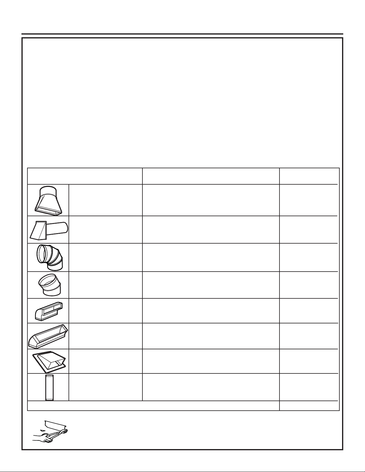
Instrucciones de Instalación
NOTA: Si usted necesita instalar conductos, tenga
pendiente que la longitud total del conducto rectangular de
31⁄4″x10″oelconductoredondode6″dediámetrono debe
sobrepasar 140 pies equivalentes.
La ventilación externa requiere un CONDUCTO DE
CAMPANA DE ESCAPE. Lea lo siguiente cuidadosamente.
NOTA: Es importante que la ventilación sea instalada
usando la ruta más directa y con la menor cantidad de codos
posible. Esto asegura la ventilación del escape y ayuda a
prevenir bloqueos. También, cerciórese de que el regulador
de tiro pende libremente y nada bloquea los conductos.
Conexiones de escape:
La campana de escape ha sido diseñada para encajar con
un conducto rectangular de 31⁄4″x10″estándar.
Si un conducto redondo es necesario, se debe usar un
adaptador de transición de rectangular a redondo. No use
un conducto menor de 6” de diámetro.
PARTES DE CONDUCTO EQUIVALENTE x USADO = EQUIVALENTE
Adaptador de transición de 5 pies x ( ) = pies
rectángulo a redondo*
LONGITUD NÚMERO LONGITUD
Longitud máxima del conducto:
Para lograr un movimiento satisfactorio del aire, la
longitud total del conducto rectangular de 31⁄4″x10″
oelconductoredondode6″dediámetrono debe
sobrepasar 140 pies equivalentes.
Los codos, transiciones, paredes y tapas
de techo, etc., presentan resistencia adicional
al flujo de aire y son equivalentes a una sección de
conducto recto el cual es más largo que su tamaño
físico real. Cuando calcule la longitud total del
conducto, agregue las longitudes equivalentes de
todas las transicionesy adaptadores, más la longitud
de todas las secciones de conducto rectas. La tabla
más adelante muestra cómo puede calcular la longitud
aproximada de la red de conductos usando pies
aproximados de longitudes equivalentes de algunos
conductos típicos.
Tapa de pared 40 pies x ( ) = pies
Codo de 90° 10 pies x ( ) = pies
Codo de 45° 5 pies x ( ) = pies
Codo de 90° 25 pies x ( ) = pies
Codo de 45° 5 pies x ( ) = pies
Tapa de techo 24 pies x ( ) = pies
6″redondo 1pies x () = pies
Conducto recto de
o rectangular de 31⁄4″x10″
* IMPORTANTE: Si se usa un adaptador de transición
de rectángulo a redondo, las esquinas del fondo del
regulador de tiros deberán ser cortadas para que encajen,
usando las tijeras de corte, para permitir el movimiento
libre del regulador de tiros.
La longitud de las partes de conductos equivalentes está
basada en pruebas reales y reflejan los requisitos para lograr
una buena ventilación con cualquier campana de escape.
4 31-7000132 Rev. 0
Page 53

Instrucciones de Instalación
DAÑO – ENVÍO/
INSTALACIÓN
• Si la unidad se daña durante el envío, devuelva
la unidad a la tienda donde fue comprada para su
reparación o reemplazo.
• Si la unidad es dañada por el cliente, la reparación
o reemplazo es responsabilidad del cliente.
• Si la unidad es dañada por el instalador (si no
es el cliente), la reparación o reemplazo deberá ser
realizado por arreglo entre el cliente y el instalador.
PARTES INCLUIDAS
PAQUETE DE PIEZAS
PARTE CANTIDAD
Tornillos de Madera
(3/16” x 2”)
Tornillos con resorte
y tuercas mariposa)
(1/4” x 3”)
Tornillo de Máquina
con Auto Alineación
(1/4”-28 x 3-1/4”)
Arandela Aislante
de Nylon (para
gabinetes
metálicos)
Tornillos de rosca
(para conectar
el conector del
conducto del
amortiguador)
Una abrazadera del
cable de corriente
y un tornillo de
montaje de color
oscuro (para
sostener el cable de
corriente)
2
4
3
2
3
1
PARTES INCLUIDAS
PIEZAS ADICIONALES
PARTE CANTIDAD
Plantilla del
≤
≤
≤
Gabinete
Superior
Plantilla de la
Pared Trasera
Instrucciones
de Instalación
Filtros de
Grasa
Placa de
montaje (para
soportar el
horno de
microondas)
Placa de
cubierta (para
instalación de
ventilación de
habitación)
1
1
1
2
1
1
Enconrará las piezas de instalación dentro de
un paquete con la unidad. Asegúrese de que se
encuentren todas las piezas.
NOTA: Se incluyen algunas piezas adicionales.
31-7000132 Rev. 0 5
Page 54
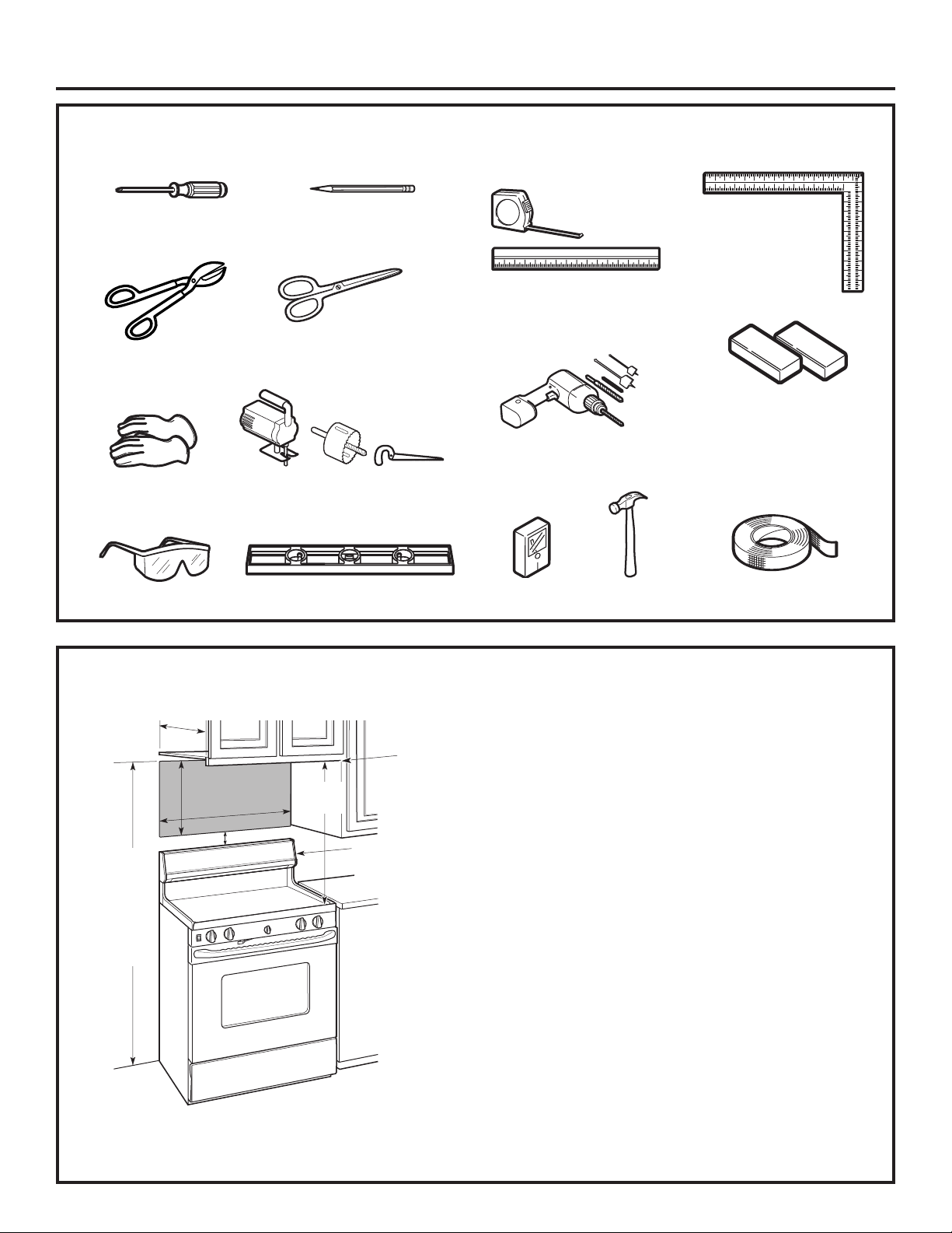
Instrucciones de Instalación
HERRAMIENTAS NECESARIAS
Destornillador
Phillips nº1 y nº2
Tijeras para hojalata
(para cortes en
reguladores, si se
requiere)
Guantes
Gafas de seguridad
Lápiz
Tijeras (para cortar
plantillas, si es necesario)
Sierra (sable, agujero o cerradura)
Nivel
Regla o cinta métrica y extremo
recto
Taladro eléctrico con brocas
de 3/15”, 7/16”, 1/2”, y 5/8”
Detector de
montantes
Martillo (opcional)
Escuadra de
carpintero
(opcional)
Bloques de llenado o piezas de
fragmentos de madera, si son
necesarios para para generar
espacio en el gabinete superior
(usados en instalaciones de
gabinetes inferiores ahuecados
únicamente)
Cinta para conductos y
de mascarar
ESPACIO DE MONTAJE
*13″max.
necesita estar
16-1⁄2″
30″
2″
66″omás
desde
el piso
hasta
la parte
superior
del horno
30″
min.
Protector posterior de
salpicaduras
superficie de la
El extremo
del fondo
del gabinete
a30″omás
a partir de la
estufa
NOTAS:
•Elespacioentrelosgabinetesdebeserde30″
de ancho y debe estar libre de obstrucciones.
• Este horno es para ser instalado por encima
deestufashasta36″deancho.
• Si el espacio entre los gabinetes es mayor a 30 ”, se puede usar
un Kit de panel de relleno para llenar el espacio entre el horno de
microondas y los gabinetes. Su manual del propietario contiene el
número de kit para su modelo.
• Si usted se dispone a ventilar su horno hacia el exterior, ver
la Sección de Campana de Escape para la preparación del
conducto de escape.
• Cuando se instale el horno debajo de gabinetes de fondos
lisos y planos, tenga cuidado de seguir cuidadosamente las
instrucciones en
la plantilla del gabinete superior para el espacio de tolerancia del
cable eléctrico.
• * Máx. de 13”: para una instalación estándar, una
profundidad del gabinete de 15” requiere pasos adicionales
utilizando el kit de instalación adicional JX15BUMPWW/BB.
• Para modelos con hoyos de ventilación superiores: No permita
que el gabinete u otros objetos bloqueen el flujo de aire de la
ventilación.
•
Los hornos microondas sobre la cocina de la marca Café sólo
se deberán instalar sobre las cocinas de la marca Café. La
instalación sobre cualquier otra cocina podrá producir como
resultado temperaturas de superficies que pueden provocar
quemaduras.
• Todos los demás hornos microondas sobre la cocina se
deberán instalar sobre cualquier superficie de cocción o
cocina con un BTU combinado superior a 60,000 BTU.
6 31-7000132 Rev. 0
Page 55

Instrucciones de Instalación
1
CÓMO COLOCAR EL PLATO DE MONTAJE
CÓMO REMOVER EL HORNO
A
.
DEL EMBALAJE / CÓMO
REMOVER EL PLATO DE
MONTAJE
Remueva la caja que contiene las instrucciones
1
de instalación, los filtros, el adaptador de escape,
el regulador de tiro, estante y la pequeña bolsa
con los elementos de instalación. No remueva la
espuma de poliestireno que protege el frente del
horno.
2
Pliegue hacia atrás las alas de la caja. Luego,
cuidadosamente ruede el horno hasta que quede
apoyado sobre la parte superior. El horno deberá
descansar sobre la espuma de poliestireno.
B
.
CÓMO ENCONTRAR LOS
POSTES DE VIGA EN LA PARED
Postes de viga
en la pared
Centro
Caja
Poliestireno
3
Tire de la caja hacia arriba y retírela del horno.
4
Ubique el horno de forma erguida. Retire y de
forma apropiada descarte las bolsas de plástico y
el embalaje de gomaespuma.
Encuentre los postes, usando uno de los
1
métodos siguientes:
A. Use un detector de postes – un dispositivo
magnético que localiza clavos.
O
B. Use un martillo para golpear ligeramente
a través de la superficie de montaje hasta
encontrar un sonido sólido. Esto indicará que
hay un poste de viga en ese lugar.
Después de localizar el poste o los postes de
2
viga, encuentre el centro mediante el análisis de
la pared usando un clavo pequeño para darse
cuenta de dónde están los bordes del poste.
Luego coloque
una marca en el centro de los bordes. El centro de
cualquier poste adyacente deberá ser entre 16” ó
24” desde esta marca.
Trace una línea hacia abajo indicando el centro
3
del poste.
EL HORNO DEBE CONECTARSE POR LO MENOS
A UN POSTE DE LA PARED.
31-7000132 Rev. 0 7
Page 56

Instrucciones de Instalación
DETERMINACIÓN DE LA UBICACIÓN DE LA PLACA DE MONTAJE
C
DEBAJO DE SU GABINETE
Posición de la Placa – debajo del
gabinete inferior plano
Dibuje una línea vertical en la pared en el centro
del espacio de 30” de ancho. Encinte la Plantilla
de la Pared Trasera sobre la pared que coincide
con la línea central y que toca la parte inferior del
gabinete.
Posición de la Placa – debajo del gabinete
inferior empotrado con frente saliente
Dibuje una línea
sobre la pared trasera
equivalente a la
profundidad del frente
saliente.
30” a la Placa de Cocción
Posición de la Placa – debajo del
gabinete inferior empotrado con marco
30” a la Placa de Cocción
Dibuje una línea vertical en la pared en el centro
del espacio de 30”.
Encinte la Plantilla de la Pared Trasera sobre la
pared que coincide con la línea central y que toca
la parte inferior del marco del gabinete.
Es posible que sus gabinetes posean bordes
decorativos que interfieran con la instalación del horno
microondas. Retire el borde decorativo para instalar
el horno microondas de forma adecuada y para que
quede nivelado.
EL HORNO MICROONDAS DEBERÁ ESTAR
NIVELADO
Use un nivel para asegurarse de que la parte inferior
del gabinete esté nivelada.
Si los gabinetes cuentan con un solo frente saliente,
sin marco trasero ni lateral, instale la placa de
montaje a la misma distancia que la profundidad del
frente saliente. Esto mantendrá el horno microondas
nivelado.
1
Mida la profundidad interna del frente saliente.
Dibuje una línea horizontal en la pared trasera
2
que posea la misma distancia debajo de la parte
inferior del gabinete que la profundidad interior del
frente saliente.
Dibuje una línea horizontal en la pared trasera
3
que posea la misma distancia debajo de la parte
inferior del gabinete que la profundidad interior del
frente saliente.
8 31-7000132 Rev. 0
Page 57

Instrucciones de Instalación
MARCA DE LOS AGUJEROS DE MONTAJE
D
OPCIÓN 1: USE LA PANTILLA DE PAPEL DE LA PARED TRASERA
30”
PRECAUCIÓN
OPTION 1
NOTE: IT IS VERY IMPORTANT TO
READ AND FOLLOW THE DIRECTIONS
IN THE INSTALLATION INSTRUCTIONS
BEFORE PROCEEDING WITH THIS
REAR WALL TEMPLATE.
This Rear Wall Template serves to position the bottom
mounting plate and to locate the horizontal exhaust
outlet.
1. Use a level to check that the template is positioned
accurately.
2. Locate and mark at least one stud on the left or
right side of the centerline.
NOTE:It is important to use at least one wood
screw mounted firmly in a stud to support the weight
of the microwave. Mark two additional, evenly spaced
locations for the supplied toggle bolts.
3. Drill holes in the marked locations. Where there is
a stud, drill a 3/16" hole for wood screws. For holes
that do not line up with a stud, drill 5/8" holes for
toggle bolts.
NOTE::DO NOT INSTALL THE MOUNTING PLATE
AT THIS TIME.
4. Remove the template from the rear wall.
5. Review the Installation Instruction book for your
installation situation.
Darle vuelta a la hoja para consultar la
versión en Español.
Locate and mark holes to align with holes in the
mounting plate.
IMPORTANT:
LOCATE AT LEAST ONE STUD ON EITHER SIDE OF
THE CENTERLINE.
MARK THE LOCATION FOR 2 ADDITIONAL, EVENLY
SPACED TOGGLE BOLTS IN THE MOUNTING PLATE
AREA.
Trim the rear wall template along the dotted line.
A
Use guantes para evitar
12"
F. CUT OUT FOR HORIZONTAL
4"
OUTSIDE EXHAUST
CUT HOLE THROUGH REAR WALL FOR EXHAUST ADAPTOR
CAUTION - IF EXHAUST ADAPTOR IS POSITIONED OUTSIDE
RECOMMENDED DIMENSION, GREASE-LADEN AIR WILL
30” MINIMUM WIDTH REQUIRED
REAR WALL TEMPLATE
C
cortes de dedos en extremos puntiagudos.
ADVERTENCIA
Riesgo de Descarga
Eléctrica. Puede ocasionar lesiones o la muerte.
Deberá tener cuidado de no taladrar sobre cableados
eléctricos dentro de paredes o gabinetes.
Esta Plantilla de la Pared Trasera sirve para ubicar los
agujeros de montaje de la placa de montaje inferior y
para ubicar la salida horizontal del escape.
1. Use un nivel para controlar que la plantilla esté
posicionada de forma correcta.
2. Ubique y marque por lo menos un montaje sobre el
lado izquierdo o derecho de la línea central.
NOTA: Es importante usar por lo menos un tornillo de
madera montado de manera firme en un montaje para
sostener el peso del horno microondas.
3/8" TO EDGE
DISCHARGE INTO HOUSE STRUCTURE
C
Locate and mark holes to align with holes in the
mounting plate.
IMPORTANT:
LOCATE AT LEAST ONE STUD ON EITHER SIDE OF
THE CENTERLINE.
MARK THE LOCATION FOR 2 ADDITIONAL, EVENLY
SPACED TOGGLE BOLTS IN THE MOUNTING PLATE
AREA.
OPTION 2
NOTE: Refer to step C “DETERMINING MOUNTING PLATE LOCATION UNDER YOUR CABINET on page 10 for aligning instructions.
STEP 1: Installer uses bracket to make 2 marks. First
STEP 3: Installer uses a level to draw a horizontal line
mark is made by using the stampled slot in bracket.
that connects the two marks made with the stamped
Second mark is made on the ouside edge of bracket.
slot in the bracket.
Horizontal line
Make a mark
Make a mark here, along
here,
inside bottom of the
STEP 4: Installer uses marks to install bracket in
even with
stamped slot provided.
bottom of
correct position. The bracket is to be installed per
stamped
standard requirements (at least one wood screw
slot
mounted in a stud, two additional evenly spaced
locations for toggle bolts). Mark hole location A,B, C and
D by placing the mounting bracket on the wall as shown
in the picture. Hole C and or D must be in a WALL STUD.
STEP 2: Installer moves bracket to the other side of
the cabinets and makes 2 more marks. Marks are the
same as STEP 1, just opposite side.
Mark hole locations for A, B, C, and D.
B
Place bracket within the lines created in previous steps.
Make a
mark here,
Make a mark here, along
STEP 5: Set mounting bracket aside and drill holes at
even with
inside bottom of the
bottom of
all marked locations. If there is a stud, drill a 3/16” hole
stamped slot provided
stamped
for wood screws. For holes that do not line up with a
(same as Step 1).
slot
stud, drill a 5/8” hole for a toggle bolt.
NOTES:
- 13” Max Cabinet Depth
- 15” deep cabinets require additional steps using
an additional installation kit: JX15BUMP
B
ACD
3. Marque la ubicación del agujero en la pared usando la
plantilla en los agujeros A y B. Marque al menos una
ubicación de agujero en el área C que se alinee con la
ubicación de un perno. Se debe utilizar un mínimo de
tres agujeros para el montaje.
4. Perfore agujeros en las ubicaciones marcadas. Donde
haya un montaje, haga un agujero de 3/16” para
tornillos de madera. Para aquellos agujeros que no
estén alineados con un montaje, haga agujeros de
5/8” para tornillos con resorte.
NOTA: NO INSTALE LA PLACA DE MONTAJE EN
ESTE MOMENTO.
5. Retire la plantilla de la pared trasera.
31-7000132 Rev. 0 9
Page 58

Instrucciones de Instalación
MARCA DE LOS AGUJEROS DE MONTAJE
D
OPCIÓN 2: USE EL SOPORTE METÁLICO COMO PLANTILLA
NOTA: Para acceder a instrucciones de alineación, consulte el paso C “DETERMINACIÓN DE LA UBICACIÓN DE LA PLACA DE
MONTAJE DEBAJO DE SU GABINETE” en la página 8.
PASO 1: Dibuje una línea vertical en la pared en el centro
del espacio de 30 ”
PASO 2: El instalador deberá usar el soporte para realizar 2
marcas. La primera marca es realizada usando la ranura estampada
en el soporte. La segunda marca es realizada en el extremo exterior
del soporte.
PASO 3: El instalador deberá usar un nivel para dibujar
una línea horizontal que conecte las dos marcas realizadas
con la ranura estampada en el soporte.
Línea horizontal
PASO 4: El instalador deberá colocar el soporte de
montaje sobre la pared, como se muestra en la imagen.
Dibuje círculos sobre la pared en los agujeros A y B. Dibuje
al menos un círculo en el área C. Al menos un círculo
DEBE alinearse con un poste de pared.
Realice una
marca aquí
sobre el extremo
exterior del
soporte.
PASO 3: El instalador deberá mover el soporte hasta
el otro lado de los gabinetes y realizar otras 2 marcas.
Las marcas son iguales que en el PASO 2, sólo que del
lado opuesto.
Realice una marca aquí, junto
con la parte inferior interna de
la ranura estampada provista.
Marque las ubicaciones
de los agujeros A, B, y zona C
A
Coloque el soporte dentro de las líneas creadas en los pasos
previos.
C
B
PASO 5: Ubique el soporte de montaje a un costado
y perfore agujeros en todas las ubicaciones marcadas. Si
hay un montaje, haga un agujero de 3/16” para tornillos de
Realice una marca aquí, junto
con la parte inferior interna de
la ranura estampada provista
(igual que en el Paso 1).
Realice una marca
aquí sobre el
extremo exterior del
soporte.
madera. Para aquellos agujeros que no estén alineados
con un montaje, haga un agujero de 5/8” para tornillos con
resorte.
10 31-7000132 Rev. 0
Page 59

Instrucciones de Instalación
2
Este horno microondas está diseñado para adaptarse a
los siguientes tres tipos de ventilación:
A. Recirculación (Sin conducto de ventilación)
B. Escape superior exterior (conducto vertical)
C. Escape posterior exterior (Conducto horizontal)
A
TIPOS DE INSTALACIÓN
RECIRCULACIÓN (SIN
CONDUCTO DE VENTILACIÓN)
(Escoja A, B o C)
NOTA: Este horno microondas es enviado ya ensamblado
para un escape superior exterior (excepto para modelos
envìados con escape de recirculaciòn). Seleccione el tipo
de ventilación requerido para su instalación y proceda
a tal sección.
B
ESCAPE SUPERIOR EXTERIOR
(CONDUCTO VERTICAL)
El adaptador está
en su lugar para
el escape superior
exterior
Ver página 12
Un Kit de accesorios de filtro de carbonilla es necesario
para el sistema sin ventilación. (Consulte su Manual del
Propietario para obtener el número del kit.)
C
ESCAPE POSTERIOR
EXTERIOR (CONDUCTO
HORIZONTAL)
Ver página 20
Ver página 16
31-7000132 Rev. 0 11
Page 60

Instrucciones de Instalación
A
RECIRCULACIÓN (Sin Conductos No Ventilados)
VISIÓN GENERAL DE LA
INSTALACIÓN
A1. ADHERA LA PLACA DE MONTAJE A LA
PARED
A2. USE LA PLANTILLA DEL GABINETE
SUPERIOR PARA LA PREPARACIÓN DEL
GABINETE SUPERIOR
A3. AJUSTE EL MOTOR DEL CALENTADOR
A4. CÓMO INSTALAR EL FILTRO DE CARBÓN
A5. MONTE EL HORNO MICROONDAS
A6. INSTALACIÓN/ REEMPLAZO DEL FILTRO DE
CARBÓN SIN ACCESO A LOS TORNILLOS
SUPERIORES Y LA UNIDAD YA FUE MONTADA
A1
ADHERA LA PLACA DE
MONTAJE A LA PAREDL
A
D
B
C
3/8" TO EDGE
OPTION 2
STEP 1:
Installer uses bracket to make 2 marks. First
DISCHARGE INTO HOUSE STRUCTURE
C
mark is made by using the stampled slot in bracket.
Second mark is made on the ouside edge of bracket.
Horizontal line
Make a mark
STEP 4:
Make a mark here, along
here,
inside bottom of the
even with
stamped slot provided.
bottom of
stamped
slot
STEP 2:
Installer moves bracket to the other side of
the cabinets and makes 2 more marks. Marks are the
same as STEP 1, just opposite side.
Make a
mark here,
Make a mark here, along
even with
inside bottom of the
bottom of
stamped slot provided
stamped
(same as Step 1).
slot
NOTES:
- 13” Max Cabinet Depth
- 15” deep cabinets require additional steps using
an additional installation kit: JX36BUMP
C
A
C
A
12"
OPTION 1
NOTE: IT IS VERY IMPORTANT TO
READ AND FOLLOW THE DIRECTIONS
IN THE INSTALLATION INSTRUCTIONS
F. CUT OUT FOR HORIZONTAL
BEFORE PROCEEDING WITH THIS
REAR WALL TEMPLATE.
4"
OUTSIDE EXHAUST
This Rear Wall Template serves to position the bottom
mounting plate and to locate the horizontal exhaust
outlet.
CUT HOLE THROUGH REAR WALL FOR EXHAUST ADAPTOR
1. Use a level to check that the template is positioned
accurately.
2. Locate and mark at least one stud on the left or
right side of the centerline.
NOTE:
It is important to use at least one wood
screw mounted firmly in a stud to support the weight
of the microwave. Mark two additional, evenly spaced
locations for the supplied toggle bolts.
3. Drill holes in the marked locations. Where there is
a stud, drill a 3/16" hole for wood screws. For holes
that do not line up with a stud, drill 5/8" holes for
toggle bolts.
NOTE::
DO NOT INSTALL THE MOUNTING PLATE
AT THIS TIME.
4. Remove the template from the rear wall.
5. Review the Installation Instruction book for your
installation situation.
Darle vuelta a la hoja para consultar la
versión en Español.
CAUTION - IF EXHAUST ADAPTOR IS POSITIONED OUTSIDE
RECOMMENDED DIMENSION, GREASE-LADEN AIR WILL
Locate and mark holes to align with holes in the
mounting plate.
IMPORTANT:
LOCATE AT LEAST ONE STUD ON EITHER SIDE OF
THE CENTERLINE.
MARK THE LOCATION FOR 2 ADDITIONAL, EVENLY
SPACED TOGGLE BOLTS IN THE MOUNTING PLATE
AREA.
Trim the rear wall template along the dotted line.
B
B
30” MINIMUM WIDTH REQUIRED
REAR WALL TEMPLATE
D
D
IMPORTANTE: NO retire
los espaciadores de cartón
entre el protector de calor y la
puerta.
Coloque la placa de montaje contra la pared e
3
inserte las tuercas mariposa en los agujeros de la
pared para montar la placa.
PRECAUCIÓN
Tenga cuidado para evitar
pellizcos en los dedos entre la parte trasera de
la placa de montaje y la pared.
Ajuste todos los tornillos. Empuje la placa hacia
4
afuera de la pared para ayudar a ajustar los
tornillos.
Adhiera la placa a la pared usando tornillos con
resortes. Por lo menos un tornillo de madera deberá
ser usado para adherir la placa al montaje de pared.
Retire las tuercas mariposa de los tornillos.
1
Inserte los tornillos en la placa de montaje a
2
través de los agujeros designados para entrar en
la placa de yeso y vuelva a ajustar las tuercas
mariposa a 3/4” sobre cada tornillo.
Para usar tornillos con resorte:
Espacio para Tornillos con Resorte
Superior al Grosor de la Pared
Tuercas mariposa
Placa de
Montaje
Tornillo
con
Resorte
Pared
Extremo del
Tornillo
USE LA PLANTILLA DEL GABINETE
A2
SUPERIOR PARA LA PREPARACIÓN
DEL GABINETE SUPERIOR
Es necesario hacer agujeros para los tornillos del
soporte superior y un agujero lo suficientemente
grande para que el cable de corriente lo pueda
atravesar.
• Lea las instrucciones sobre la PLANTILLA DEL
GABINETE SUPERIOR.
• Pegue la misma debajo del gabinete superior.
• Haga los agujeros siguiendo las instrucciones en la
PLANTILLA DEL GABINETE SUPERIOR..
PRECAUCIÓN
inferior del gabinete.
Use gafas de seguridad al
realizar agujeros en la parte
12 31-7000132 Rev. 0
Page 61

Instrucciones de Instalación
A3.
CONTROLE LA
ORIENTACIÓN DEL MOTOR
DEL CALEFACTOR
La abertura de la cuchilla del flan del soplador debe estar
orientada hacia el frente del microondas. Deberá quitar la placa
de cubierta superior para verificar la orientación de las aspas
del ventilador. Si la abertura del ventilador ya está orientada
hacia el frente del microondas, salte al paso A5. De lo contrario,
continúe con el Paso A4 para ajustar la orientación del motor
del ventilador.
4
Ruede la unidad del calefactor 90º de forma tal
que las aberturas de la paleta del ventilador estén
orientadas hacia el frente del horno.
ANTES: Las aberturas del ventilador están
orientadas hacia arriba
A4.
CÓMO ADAPTAR EL
CALEFACTOR PARA
LA RECIRCULACIÓN
NOTA: El adaptador de escape con calefactor no es
necesario para los modelos de recirculación. Quizás
desee guardarlos para posibles usos futuros.
Retire y guarde los tornillos que sujetan la placa del
1
soplador al horno.
Tornillos del plato
del calefactor
Plato del calefactor
Parte posterior
del horno
Tornillo del motor
del calefactor
Placa de cubierta
Deslice el plato calefactor por debajo de su
2
reborde de retención y remueva el. Retire la placa
de cubierta instalada en la parte posterior. Retire
y guarde los tornillos que sujetan la unidad de
soplador al horno
Reborde de
retención
Ruede
DESPUES: Las aberturas de la paleta del
ventilador están orientadas hacia atrás
Plato
calefactor
Cuidadosamente tire del calefactor. Los alambres
3
se extenderán lo suficiente para permitirle que
usted ajuste la unidad del calefactor.
31-7000132 Rev. 0 13
Page 62

Instrucciones de Instalación
PRECAUCIÓN
A4.
CÓMO ADAPTAR EL
CALEFACTOR PARA LA
RECIRCULACIÓN (continuación)
Coloque la unidad del calefactor de nuevo en la abertura
5
Cerciórese de que los alambres no están
pellizcados.
Vuelva a colocar los tornillos del motor del ventilador que
6
retiró en el Paso 2. Deslice la placa de la cubierta en
su posición en la parte posterior de la unidad. Vuelva a
colocar la placa del ventilador y los tornillos que retiró en
el paso 1. Coloque la segunda placa de cubierta en la
placa del ventilador (incluido un tornillo).
Tornillos
del plato
calefactor
No tire ni estire los
cables del calefactor.
Placa de
cubierta
Plato del calefactor
Parte posterior
del horno
Tornillos del motor
del calefactor
Placa de
cubierta
NOTA: Cuando se encuentre
montando el horno, enrosque
el cable eléctrico a través
.
del agujero en el fondo del
gabinete superior. Manténgalo
tenso a través de los Pasos del
1-3. No pellizque el cable ni
tire el horno por el cable.
Gire el frente del horno
2
contra el fondo del
gabinete.
Frente del gabinete
Estante del fondo del gabinete
Levante el horno,
1
inclínelo hacia
adelante, y enganche
las ranuras en el
extremo inferior
posterior en dos
orejillas inferiores
del plato de montaje.
Bloque de relleno
Equivalente a
la profundidad
del retroceso
del gabinete
A5.
PARA UNA INSTALACIÓN MÁS FÁCIL Y EN POS DE LA
SEGURIDAD PERSONAL, SE RECOMIENDA QUE DOS
PERSONAS INSTALEN ESTE HORNO.
IMPORTANTE: No agarre ni use la manija de la puerta
durante la instalación.
NOTA: Si su gabinete es de metal, use la arandela de nilón
alrededor del cable eléctrico para evitar que el mismo sea
cortado.
NOTA: Recomendamos el uso de bloques de relleno si
el frente del gabinete cuelga por debajo del estante del fondo
del gabinete.
IMPORTANTE: Si no se usan bloques de relleno, podrían
ocurrir daños por apretar demasiado los tornillos.
MONTAJE DEL HORNO
Tornillos autoalineables
Parte superior del horno
14 31-7000132 Rev. 0
Page 63

Instrucciones de Instalación
A5.
MONTAJE DEL HORNO
(continuación)
Pegue el horno a la parte superior del gabinete
3
insertando dos tornillos autoalineables a través
de los agujeros exteriores superiores del horno.
Gire dos vueltas completas en cada tornillo.
Cerciórese de mantener el cable eléctrico
estirado. Tenga cuidado de no pellizcar el
cable, especialmente cuando se monte al nivel
del fondo del gabinete.
4
Apriete totalmente los dos tornillos hacia el horno
superior. (Mientras aprieta los tornillos, mantenga
el horno en su lugar contra la pared y el gabinete
superior.)
A6.
QUANDO REEMPLACE EL
FILTRO DE CARBONILLA
Si el modelo no tiene ventilación al exterior, el aire
recirculará por un filtro de carbonilla desechable que
ayuda a eliminar el humo y los olores.
El filtro de carbonilla debe reemplazarse cuando
esté visiblemente sucio o decolorado (por lo general,
después de 6 a 12 meses, según el uso que se le dé a
la campana). Consulte el Manual del Propietario para
obtener el número de kit del filtro.
Para reemplazar el filtro de carbonilla:
Abra la puerta del horno microondas.
1
Remueva los 2 tornillos en la parte superior de
2
la rejilla usando un destornillador de estrella.
(Puede ser que necesite abrir las puertas del
armario para quitar los tornillos.)
Deslice la rejilla hacia la izquierda y adelante para
3
retirar la misma.
Filtro de
carbonilla
Instale los filtros de grasa. Ver el Manual del
5
Propietario que viene con el horno.
31-7000132 Rev. 0 15
Deslice el filtro viejo hacia el frente del horno y
4
retírelo.
Retire el plástico y la envoltura del nuevo filtro e
5
instálelo. Cuando se instala correctamente, la malla
de alambre del filtro debe ser visible desde el frente.
6
Reemplace la rejilla con los dos 2 tornillos.
7
Cierre la puerta.
Inserte la malla hacia abajo
Page 64

Instrucciones de Instalación
PRECAUCIÓN
B
VISIÓN GENERAL DE LA
INSTALACIÓN
B1. Adjunte la Placa de Montaje a la
B2. Prepare el Gabinete Superior
B3. Ajuste el Motor del Calentador
B4. Ventilación Externa
B5. Nstalación Del Adaptador
B6. Montar El Horno
B7. Cómo Ajustar El Adaptador
B8. Cómo Conectar
VENTILACIÓN SUPERIOR EXTERIOR (Conducto Vertical)
Pared
De Escape
El Conducto
3/8" TO EDGE
4"
D
12"
F. CUT OUT FOR HORIZONTAL
OUTSIDE EXHAUST
CUT HOLE THROUGH REAR WALL FOR EXHAUST ADAPTOR
CAUTION - IF EXHAUST ADAPTOR IS POSITIONED OUTSIDE
RECOMMENDED DIMENSION, GREASE-LADEN AIR WILL
DISCHARGE INTO HOUSE STRUCTURE
30” MINIMUM WIDTH REQUIRED
REAR WALL TEMPLATE
C
C
OPTION 1
NOTE: IT IS VERY IMPORTANT TO
READ AND FOLLOW THE DIRECTIONS
IN THE INSTALLATION INSTRUCTIONS
BEFORE PROCEEDING WITH THIS
REAR WALL TEMPLATE.
This Rear Wall Template serves to position the bottom
mounting plate and to locate the horizontal exhaust
outlet.
1. Use a level to check that the template is positioned
accurately.
2. Locate and mark at least one stud on the left or
right side of the centerline.
NOTE:
It is important to use at least one wood
screw mounted firmly in a stud to support the weight
of the microwave. Mark two additional, evenly spaced
locations for the supplied toggle bolts.
3. Drill holes in the marked locations. Where there is
a stud, drill a 3/16" hole for wood screws. For holes
that do not line up with a stud, drill 5/8" holes for
toggle bolts.
NOTE::
DO NOT INSTALL THE MOUNTING PLATE
AT THIS TIME.
4. Remove the template from the rear wall.
5. Review the Installation Instruction book for your
installation situation.
Darle vuelta a la hoja para consultar la
versión en Español.
Locate and mark holes to align with holes in the
mounting plate.
IMPORTANT:
LOCATE AT LEAST ONE STUD ON EITHER SIDE OF
THE CENTERLINE.
MARK THE LOCATION FOR 2 ADDITIONAL, EVENLY
SPACED TOGGLE BOLTS IN THE MOUNTING PLATE
AREA.
Trim the rear wall template along the dotted line.
B
D
B
NOTES:
- 13” Max Cabinet Depth
- 15” deep cabinets require additional steps using
an additional installation kit: JX36BUMP
C
A
STEP 1:
mark is made by using the stampled slot in bracket.
Second mark is made on the ouside edge of bracket.
Make a mark
here,
even with
bottom of
stamped
slot
STEP 2:
the cabinets and makes 2 more marks. Marks are the
same as STEP 1, just opposite side.
Installer uses bracket to make 2 marks. First
Installer moves bracket to the other side of
OPTION 2
Horizontal line
STEP 4:
Make a mark here, along
inside bottom of the
stamped slot provided.
Make a
mark here,
Make a mark here, along
even with
inside bottom of the
bottom of
stamped slot provided
stamped
(same as Step 1).
slot
A
IMPORTANTE: NO retire los
espaciadores de cartón entre el
protector de calor y la puerta.
ADHIERA LA PLACA DE
B1
MONTAJE A LA PARED
A
D
B
Adhiera la placa a la pared usando tornillos con
resortes. Por lo menos un tornillo de madera deberá
ser usado para adherir la placa al montaje de pared.
Las ubicaciones recomendadas sobre la placa de
pared están indicadas por A, B, C y D.
1
Retire las tuercas mariposa de los tornillos.
2
Inserte los tornillos en la placa de montaje a
través de los agujeros designados para entrar en
la placa de yeso y vuelva a ajustar las tuercas
mariposa a 3/4” sobre cada tornillo.
C
PARA USAR TORNILLOS CON RESORTE:
Espacio para Tornillos con Resorte
Placa
de
Montaje
Inserte las tuercas mariposa en los agujeros de la
3
pared y coloque la placa de montaje contra la pared.
entre la parte trasera de la placa de montaje y la
pared.
Ajuste todos los tornillos. Empuje la placa hacia
4
afuera de la pared para ayudar a ajustar los
tornillos.
Superior al Grosor de la Pared
Tuercas Mariposa
Tornillo con
Resorte
Pared
Placa de Montaje
Tenga cuidado para evitar
pellizcos en los dedos
Extremo del Tornillo
16 31-7000132 Rev. 0
Page 65

Instrucciones de Instalación
PRECAUCIÓN
B2.
Deberá perforar agujeros para los tornillos de apoyo
superiores, un agujero suficientemente grande para que
el cable eléctrico quepa, y un recorte lo suficientemente
grande como para que el adaptador de escape pueda ser
introducido.
• Lea las instrucciones sobre la PLANTILLA DEL
• Péguelo debajo del gabinete superior.
• Taladre los agujeros, siguiendo las instrucciones en la
perfore los agujeros en el fondo del gabinete.
USE LA PLANTILLA DEL
GABINETE SUPERIOR PARA
LA PREPARACIÓN DEL
GABINETE
B
D
GABINETE SUPERIOR.
PLANTILLA DEL GABINETE SUPERIOR.
C
A
Use gafas de seguridad cuando
Deslice el plato calefactor por debajo de su
2
lengüeta de contención y levante el mismo. Retire
la placa de cubierta instalada en la parte posterior.
Retire y guarde los tornillos que sujetan la unidad
de soplador al horno
Reborde de
retención
Plato
calefactor
Tornillos del motor
del calefactor
Placa de
cubierta
3
Con cuidado, empuje hacia usted la unidad
del calefactor. Los cables se extenderán lo
suficiente como para permitirle ajustar la unidad
del calefactor.
B3.
CONTROLE LA
ORIENTACIÓN DEL MOTOR
DEL CALEFACTOR
La abertura de las paletas del ventilador del calefactor deben
apuntar hacia la parte superior del horno microondas. Si
la abertura del ventilador ya está apuntada hacia la parte
superior del horno microondas, vaya directo al Paso B5.
De otro modo, continúe con el Paso B4 para ajustar la
orientación del motor.
B4.
ADAPTACIÓN DEL
CALEFACTOR PARA LA
VENTILACIÓN EXTERNA
Retire la cubierta instalada en la placa del ventilador
1
(incluido un tornillo). Retire y guarde los tornillos que
sujetan la placa del soplador al horno
Placa de
cubierta
Tornillos
del Plato
Calefactor
Plato Calefactor
Parte Trasera
del Horno
4
Haga rodar la unidad del calefactor 90º, de modo
que las aberturas de las paletas del ventilador
enfrenten la parte superior del horno.
ANTES:
Aberturas de
las Paletas
del Ventilador
Hacia el
Frente
Girar
DESPUÉS:
Aberturas de
las Paletas
del Ventilador
Hacia Arriba
Placa de
cubierta
31-7000132 Rev. 0 17
Page 66

Instrucciones de Instalación
PRECAUCIÓN
B4.
Vuelva a colocar la unidad del calefactor en la
5
6
Tornillos
del Plato
del
Calefactor
CALEFACTOR PARA LA
VENTILACIÓN EXTERNA
abertura.
(cont.)
No empuje ni extienda
el cableado de la unidad del calefactor.
Asegúrese de que los cables no posean cortes.
Vuelva a colocar los tornillos del motor del
ventilador que retiró en el paso 2. Deslice la placa
de la cubierta en su posición en la parte posterior
de la unidad. Vuelva a colocar la placa del
ventilador y los tornillos que retiró en el paso 1
Plato del
Calefactor
Parte Trasera
del Horno
Tornillo del Motor
del Calefactor
Placa de
cubierta
B5.
ENSAMBLAJE E INSTALACIÓN
DEL ADAPTADOR
Regulador de
tiro
B6.
PARA OBTENER UNA INSTALACIÓN MÁS FÁCIL
Y EN POS DE LA SEGURIDAD PERSONAL, SE
RECOMIENDA QUE DOS PERSONAS INSTALEN
ESTE HORNO.
IMPORTANTE: No agarre ni use la manija de la
puerta durante la instalación.
NOTA: Si su gabinete es de metal, use la arandela
de nilón alrededor del cable eléctrico para evitar
que el mismo sea cortado.
NOTA: Recomendamos el uso de bloques de
relleno si el frente del gabinete cuelga por debajo
del estante del fondo del gabinete.
IMPORTANTE: Si no se usan bloques de relleno,
podrían ocurrir daños por apretar demasiado los
tornillos.
1
CÓMO MONTAR EL HORNO
Levante el horno microondas, incline el mismo
hacia adelante, y enganche las ranuras en
el extremo inferior trasero sobre las cuatro
lengüetas inferiores de la placa de montaje
Gire el frente del horno microondas contra la
parte inferior del gabinete.
Cable de
Corriente
Adaptador
de escape
Plato del
calefactor
Parte posterior
del horno
Placa de cubierta
NOTA: En algunos modelos, es posible que el adaptador de escape
y la unidad del regulador de tiro ya estén colocados en el horno.
1
Coloque el horno en su posición vertical, con la parte
superior hacia arriba.
NOTA: Cerciórese de que las paletas del ventilador
calefactor sean visibles y estén orientadas hacia arriba.
Inserte las orejillas en cada lado del regulador de tiro en
2
los agujeros en el interior posterior del adaptador.
Pegue el adaptador de escape al plato calefactor con los
3
dos tornillos de bronce que le proporcionamos.
Cerciórese de que el regulador de tiro gira fácilmente
antes de montar el horno.
Deberá hacer ajustes para asegurarse de que existe
alineación apropiada con el sistema de conductos de su
casa después de la instalación del horno.
Gire el frente del horno contra la parte inferior del
2
gabinete.
18 31-7000132 Rev. 0
Page 67

Instrucciones de Instalación
B6.
Pegue el horno a la parte superior del gabinete
3
CÓMO MONTAR EL HORNO
(continuación)
Frente del gabinete
Estante del fondo del gabinete
Bloque de relleno
Equivalente a
la profundidad
del retroceso
del gabinete
Tornillo autoalineable
Parte superior del horno
insertando dos tornillos autoalineables a través de
los agujeros exteriores superiores del horno. Gire
dos vueltas completas en cada tornillo. Cerciórese
de mantener el cable eléctrico estirado. Tenga
cuidado de no pellizcar el cable, especialmente
cuando se monte al nivel del fondo del gabinete.
B7.
CÓMO AJUSTAR EL
ADAPTADOR DE ESCAPE
Abra el gabinete superior y ajuste el adaptador de
escape para conectarlo al conducto de la casa.
Regulador de tiro
Parte posterior
del horno
Placa de
cubierta
B8.
CÓMO CONECTAR
EL CONDUCTO
Conducto de la casa
Apriete complemente los dos tornillos hacia la parte
4
de arriba del horno. (Mientras aprieta los tornillos,
mantenga el horno en su lugar contra la parte y el
gabinete superior).
Extienda el conducto de la casa hacia abajo
1
para conectarlo con el adaptador de escape.
Selle las juntas del conducto de escape usando
2
cinta adhesiva de conductos.
Instale los filtros de grasa. Ver el Manual del
5
Propietario que viene con el horno.
31-7000132 Rev. 0 19
Page 68

Instrucciones de Instalación
CUT HOLE THROUGH REAR WALL FOR EXHAUST ADAPTOR
12"
4"
NOTE: IT IS VERY IMPORTANT TO
READ AND FOLLOW THE DIRECTIONS
IN THE INSTALLATION INSTRUCTIONS
BEFORE PROCEEDING WITH THIS
REAR WALL TEMPLATE.
This Rear Wall Template serves to position the bottom
mounting plate and to locate the horizontal exhaust
outlet.
1. Use a level to check that the template is positioned
accurately.
2. Locate and mark at least one stud on the left or
right side of the centerline.
NOTE:
It is important to use at least one wood
screw mounted firmly in a stud to support the weight
of the microwave. Mark two additional, evenly spaced
locations for the supplied toggle bolts.
3. Drill holes in the marked locations. Where there is
a stud, drill a 3/16" hole for wood screws. For holes
that do not line up with a stud, drill 5/8" holes for
toggle bolts.
NOTE::
DO NOT INSTALL THE MOUNTING PLATE
AT THIS TIME.
4. Remove the template from the rear wall.
5. Review the Installation Instruction book for your
installation situation.
Darle vuelta a la hoja para consultar la
versión en Español.
CAUTION - IF EXHAUST ADAPTOR IS POSITIONED OUTSIDE
RECOMMENDED DIMENSION, GREASE-LADEN AIR WILL
DISCHARGE INTO HOUSE STRUCTURE
30” MINIMUM WIDTH REQUIRED
REAR WALL TEMPLATE
F. CUT OUT FOR HORIZONTAL
OUTSIDE EXHAUST
Locate and mark holes to align with holes in the
mounting plate.
IMPORTANT:
LOCATE AT LEAST ONE STUD ON EITHER SIDE OF
THE CENTERLINE.
MARK THE LOCATION FOR 2 ADDITIONAL, EVENLY
SPACED TOGGLE BOLTS IN THE MOUNTING PLATE
AREA.
Trim the rear wall template along the dotted line.
3/8" TO EDGE
C
A
C
D
B
NOTES:
- 13” Max Cabinet Depth
- 15” deep cabinets require additional steps using
an additional installation kit: JX36BUMP
OPTION 1
OPTION 2
STEP 1:
Installer uses bracket to make 2 marks. First
mark is made by using the stampled slot in bracket.
Second mark is made on the ouside edge of bracket.
STEP 2:
Installer moves bracket to the other side of
the cabinets and makes 2 more marks. Marks are the
same as STEP 1, just opposite side.
STEP 4:
Make a mark here, along
inside bottom of the
stamped slot provided.
Make a mark
here,
even with
bottom of
stamped
slot
Make a mark here, along
inside bottom of the
stamped slot provided
(same as Step 1).
Make a
mark here,
even with
bottom of
stamped
slot
Horizontal line
A
C
D
B
PRECAUCIÓN
C
VENTILACIÓN EXTERIOR TRASERA (Conducto Horizontal)
VISIÓN GENERAL DE LA
INSTALACIÓN
C1. Prepare la Pared Trasera
C2. Adjunte la Placa de Montaje
a la Pared
C3. Prepare el Gabinete Superior
C4. Ajuste el Calentador
C5. Monte el Horno Microondas
PREPARACIÓN DE LA PARED
C1
TRASERA PARA EL ESCAPE
EXTERNO TRASERO
Es necesario cortar una abertura en la pared trasera
del escape externo.
ADHIERA LA PLACA DE
C2
MONTAJE A LA PARED
B
D
C
A
• Lea las instrucciones sobre la PLANTILLA DE LA
PARED TRASERA.
• Pegue la misma a la pared trasera, alineándola
con los agujeros previamente perforados A y B
en la placa de montaje.
• Corte la apertura, siguiendo las instrucciones de
la PLANTILLA DE LA PARED TRASERA.
A
D
B
C
Adhiera la placa a la pared usando tornillos con
resortes. Por lo menos un tornillo de madera deberá
ser usado para adherir la placa al montaje de pared.
1
Retire las tuercas mariposa de los tornillos.
Inserte los tornillos en la placa de montaje a través
2
de los agujeros designados para entrar en la placa
de yeso y vuelva a ajustar las tuercas mariposa a
3/4” sobre cada tornillo.
Para usar tornillos con resorte:
Espacio para Tornillos con Resorte
Superior al Grosor de la Pared
Placa de
Montaje
Coloque la placa de montaje contra la pared e
3
inserte las tuercas mariposa en los agujeros de la
pared para montar la placa
pellizcos en los dedos entre la parte trasera de la
placa de montaje y la pared.
4
Ajuste todos los tornillos. Empuje la placa hacia
afuera de la pared para ayudar a ajustar los tornillos.
Tuercas Mariposa
Tornillo con
Resorte
Pared
Tenga cuidado para evitar
Extremo del Tornillo
20 31-7000132 Rev. 0
Page 69

Instrucciones de Instalación
PRECAUCIÓN
C3.
USE LA PLANTILLA DEL
GABINETE SUPERIOR PARA
PREPARAR EL GABINETE
SUPERIOR
Necesita perforar agujeros para los tornillos de apoyo
superiores y un agujero suficientemente grande para
que el cable eléctrico quepa.
B
D
C
A
• Lea las instrucciones sobre la PLANTILLA DEL
GABINETE SUPERIOR.
• Péguela debajo del gabinete superior.
• Taladre los agujeros, siguiendo las instrucciones en la
PLANTILLA DEL GABINETE SUPERIOR.
C4.
CÓMO ADAPTAR EL
CALEFACTOR PARA EL ESCAPE
POSTERIOR EXTERNO
Retire y guarde los dos tornillos que sujetan la
1
placa del ventilador en su lugar. Deslice la placa del
ventilador por debajo de su brida de retención. Retire
la placa de cubierta instalada en la parte posterior.
Retire y guarde los tornillos que sujetan la unidad de
soplador al horno
Reborde de
retención
Cuidadosamente tire del calefactor. Los alambres
2
se extenderán lo suficiente como para permitirle
que usted ajuste la unidad del calefactor.
ANTES: Las aberturas del ventilador están
orientadas hacia arriba
Plato
calefactor
Use gafas de seguridad
cuando perfore los agujeros en el fondo del
gabinete.
Parte posterior
del horno
Rote la unidad 180° en sentido contrario a las
3
agujas del reloj.
Antes de la rotación
Parte posterior
del horno
Ruede la unidad del calefactor 90º de forma tal
4
que las aberturas de la paleta del ventilador estén
orientadas hacia la parte posterior del horno.
Antes de la rotación
Después de la rotación
Parte posterior
del horno
Después de la rotación
Parte posterior
del horno
31-7000132 Rev. 0 21
Parte posterior
del horno
Page 70

Instrucciones de Instalación
PRECAUCIÓN
PRECAUCIÓN
Localice los dos platos removibles en el panel
5
posterior del horno, cerca de la parte superior
del horno.
Usando tijeras, cuidadosamente corte el área
de telaraña de los dos agujeros lado a lado
(que aseguran los platos removibles al horno).
Corte las cuatro telarañas en ambos platos
removibles posteriores; esto permitirá que el
flujo de aire del ventilador escape hacia la parte
posterior del horno.
los extremos filosos de las aberturas
después de remover los platos.
Parte posterior del horno
Coloque la unidad del calefactor de nuevo en
6
la abertura.
Cerciórese de recortar
Corte con tijeras
las cuatro telarañas
de cada panel
removible y
remueva los discos
removibles de metal
para permitir el flujo
de aire posterior.
C5.
PARA UNA INSTALACIÓN MÁS FÁCIL Y EN POS
DE LA SEGURIDAD PERSONAL, SE RECOMIENDA
QUE DOS PERSONAS INSTALEN ESTE HORNO.
IMPORTANTE: No agarre ni use la manija de la
puerta durante la instalación.
NOTA: Si su gabinete es de metal, use la arandela
de nilón alrededor del cable eléctrico para evitar que
el mismo sea cortado.
NOTA: Recomendamos el uso de bloques de relleno
si el frente del gabinete cuelga por debajo del
estante del fondo del gabinete.
IMPORTANTE: Si no se usan bloques de relleno,
podrían ocurrir daños por apretar demasiado los
tornillos.
MONTAJE DEL HORNO
DESPUES: Las aberturas de la paleta del
ventilador están orientadas hacia atrás
No tire ni estire los
cables del calefactor. Cerciórese de
que los alambres no están pellizcados.
NOTA: Las aberturas del escape del calefactor
deberán encajar con las aberturas del escape en
la parte posterior del horno.
Coloque el plato calefactor en la misma posición
7
como estaba antes y reinstale los tornillos del
plato calefactor y del motor del calefactor. Retire
la tapa instalada en la parte posterior.
Placa de
cubierta
Tornillos
del plato
calefactor
Plato calefactor
Parte posterior
del horno
Levante el horno microondas, incline el mismo
1
hacia adelante, y enganche las ranuras en
el extremo inferior trasero sobre las cuatro
lengüetas inferiores de la placa de montaje
Rotate front of microwave oven up against
cabinet bottom.
Cable de
Corriente
Gire el frente del horno contra la parte inferior del
2
gabinete.
Tornillos del motor
de calefactor
22 31-7000132 Rev. 0
Page 71

Instrucciones de Instalación
Frente del gabinete
Estante del fondo del gabinete
Filler Block
Equivalente
a la
profundidad
del retroceso
del gabinete
Tornillos autoalineables
Parte superior del horno
Pegue el horno a la parte superior del gabinete
3
insertando dos tornillos autoalineables a través de
los agujeros exteriores superiores del horno. Gire
dos vueltas completas en cada tornillo. Cerciórese
de mantener el cable eléctrico estirado. Tenga
cuidado de no pellizcar el cable, especialmente
cuando se monte al nivel del fondo del gabinete.
Apriete totalmente los dos tornillos hacia el horno
4
superior. (Mientras aprieta los tornillos, mantenga
el horno en su lugar contra la pared y el gabinete
superior.)
Instale los filtros de grasa. Ver el Manual del
5
Propietario que viene con el horno.
31-7000132 Rev. 0 23
Page 72
QUICK
USE & CARE
Instrucciones de Instalación
ANTES DE USAR EL HORNO MICROONDAS
Asegúrese de que el horno microondas haya
1
sido instalado de acuerdo con las instrucciones.
Retire todos los materiales de embalaje del
2
horno microondas.
Instale el plato giratorio y el anillo del plato
3
giratorio en la cavidad.
Reemplace el fusible del hogar o vuelva a
4
activar el disyuntor.
Lea la sección de Uso y Cuidado Rápido.
6
MANTENGA LAS INSTRUCCIONES
7
DE INSTALACIÖN PARA USO DEL
INSPECTOR LOCAL.
Modelos de 120 V: Enchufe el cable de
5
corriente en un tomacorriente eléctrico
específico de 15 a 20 amp.
Asegúrese de contar
con una conexión
a tierra adecuada
antes de usar.
Cuando se encuentre un tomacorriente de pared
de dos enchufes, es muy importante reemplazarlo
por uno conectado a tierra de forma adecuada de
tres cables, instalado por un electricista calificado.
24 31-7000132 Rev. 0
 Loading...