

Page 1
GE Oil & Gas
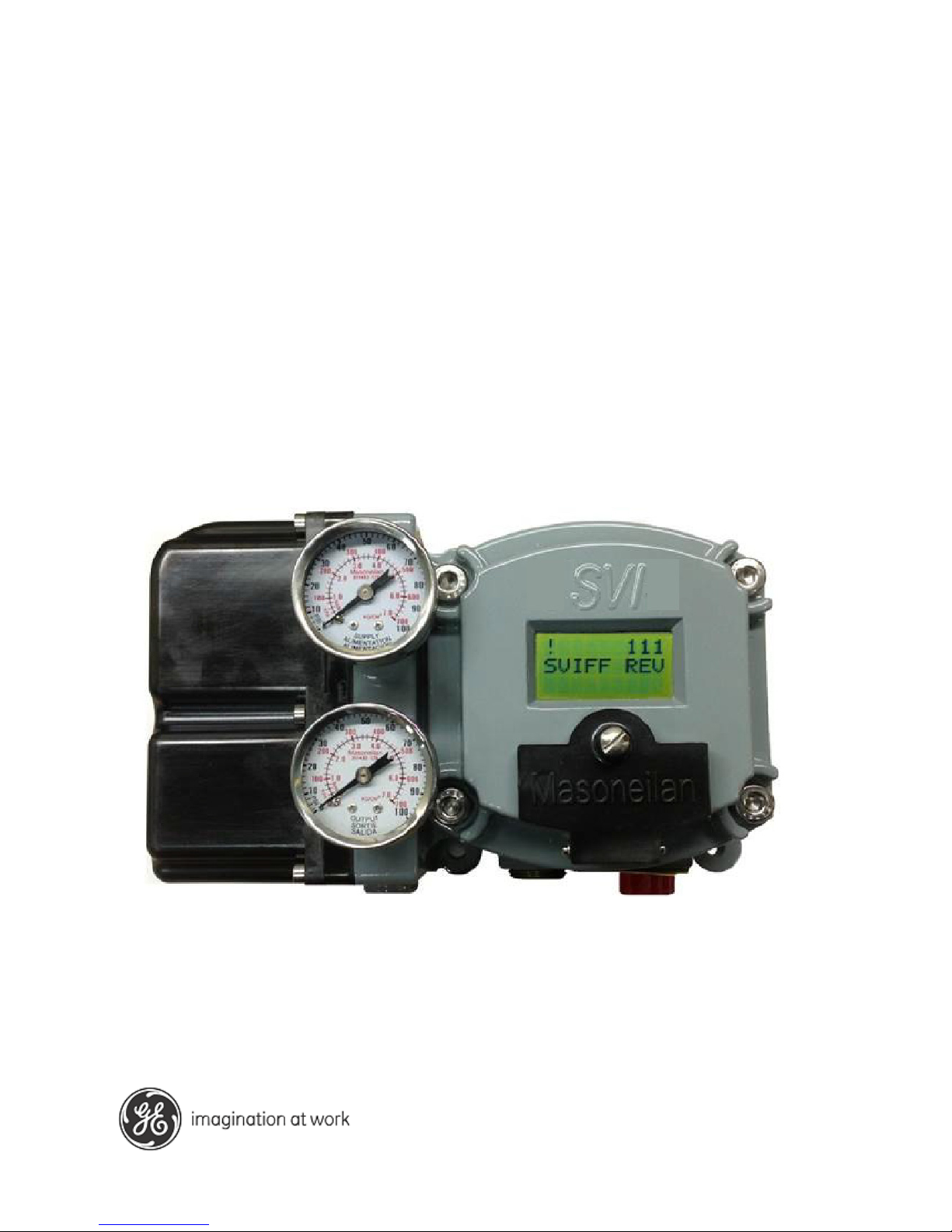
Masoneilan* SVI* FF Digital Positioner
Quick Start Guide
(Rev. D)
GE Data Classification: Public
Page 2

© 2017 General Electric Company. All rights reserved.
2 | =GE Oil & Gas
About this Guide
This instruction manual applies to the following instruments and approved software:
SVI FF
with Firmware version 1.0.0.1 or higher
with ValVue* version 3.0
with handheld communicator with DD published for SVI FF
All information contained herein is believed to be accurate at the time of publication and is subject to
change without notice.
The information contained in this manual, in whole or part, shall not be transcribed or copied without GE Oil
& Gas’ written permission.
In no case does this manual guarantee the merchantability of the positioner or the software or its adaptability to a specific client needs.
Please report any errors or questions about the information in this manual to your local supplier or visit
www.geoilandgas.com/valves.
DISCLAIMER
THESE INSTRUCTIONS PROVIDE THE CUSTOMER/OPERATOR WITH IMPORTANT PROJECT-SPECIFIC REFERENCE INFORMATION IN ADDITION TO THE CUSTOMER/OPERATOR’S NORMAL OPERATION AND MAINTENANCE PROCEDURES. SINCE OPERATION AND MAINTENANCE PHILOSOPHIES VARY, GE (GENERAL
ELECTRIC COMPANY AND ITS SUBSIDIARIES AND AFFILIATES) DOES NOT ATTEMPT TO DICTATE SPECIFIC
PROCEDURES, BUT TO PROVIDE BASIC LIMITATIONS AND REQUIREMENTS CREATED BY THE TYPE OF
EQUIPMENT PROVIDED.
THESE INSTRUCTIONS ASSUME THAT OPERATORS ALREADY HAVE A GENERAL UNDERSTANDING OF THE
REQUIREMENTS FOR SAFE OPERATION OF MECHANICAL AND ELECTRICAL EQUIPMENT IN POTENTIALLY
HAZARDOUS ENVIRONMENTS. THEREFORE, THESE INSTRUCTIONS SHOULD BE INTERPRETED AND
APPLIED IN CONJUNCTION WITH THE SAFETY RULES AND REGULATIONS APPLICABLE AT THE SITE AND
THE PARTICULAR REQUIREMENTS FOR OPERATION OF OTHER EQUIPMENT AT THE SITE.
THESE INSTRUCTIONS DO NOT PURPORT TO COVER ALL DETAILS OR VARIATIONS IN EQUIPMENT NOR TO
PROVIDE FOR EVERY POSSIBLE CONTINGENCY TO BE MET IN CONNECTION WITH INSTALLATION, OPERATION OR MAINTENANCE. SHOULD FURTHER INFORMATION BE DESIRED OR SHOULD PARTICULAR PROBLEMS ARISE WHICH ARE NOT COVERED SUFFICIENTLY FOR THE CUSTOMER/OPERATOR'S PURPOSES THE
MATTER SHOULD BE REFERRED TO GE.
THE RIGHTS, OBLIGATIONS AND LIABILITIES OF GE AND THE CUSTOMER/OPERATOR ARE STRICTLY LIMITED TO THOSE EXPRESSLY PROVIDED IN THE CONTRACT RELATING TO THE SUPPLY OF THE EQUIPMENT.
NO ADDITIONAL REPRESENTATIONS OR WARRANTIES BY GE REGARDING THE EQUIPMENT OR ITS USE
ARE GIVEN OR IMPLIED BY THE ISSUE OF THESE INSTRUCTIONS.
THESE INSTRUCTIONS CONTAIN PROPRIETARY INFORMATION OF GE, AND ARE FURNISHED TO THE CUSTOMER/OPERATOR SOLELY TO ASSIST IN THE INSTALLATION, TESTING, OPERATION, AND/OR MAINTENANCE OF THE EQUIPMENT DESCRIBED. THIS DOCUMENT SHALL NOT BE REPRODUCED IN WHOLE OR IN
PART NOR SHALL ITS CONTENTS BE DISCLOSED TO ANY THIRD PARTY WITHOUT THE WRITTEN
APPROVAL OF GE.
Copyright
Copyright 2017 by GE Oil & Gas. All rights reserved. PN 720023977-888-0000 Rev. D.
Page 3

Document Changes
Version/Date Changes
B/12-14 Updated headers and footers.
Made a few changes to Quick Start section
Changed ES-776 to Rev J.
C/02-15 Changed ES-776 to Rev. K and to Declaration of
Conformity
D/03-17 Changed ES-776 to Rev. L.
© 2017 General Electric Company. All rights reserved.
Masoneilan SVI FF Positioner Quick Start Guide =| 3
Page 4

This page intentionally left blank.
Page 5
Masoneilan SVI FF Positioner Quick Start Guide =| 5
© 2017 General Electric Company. All rights reserved
.
Safety Information
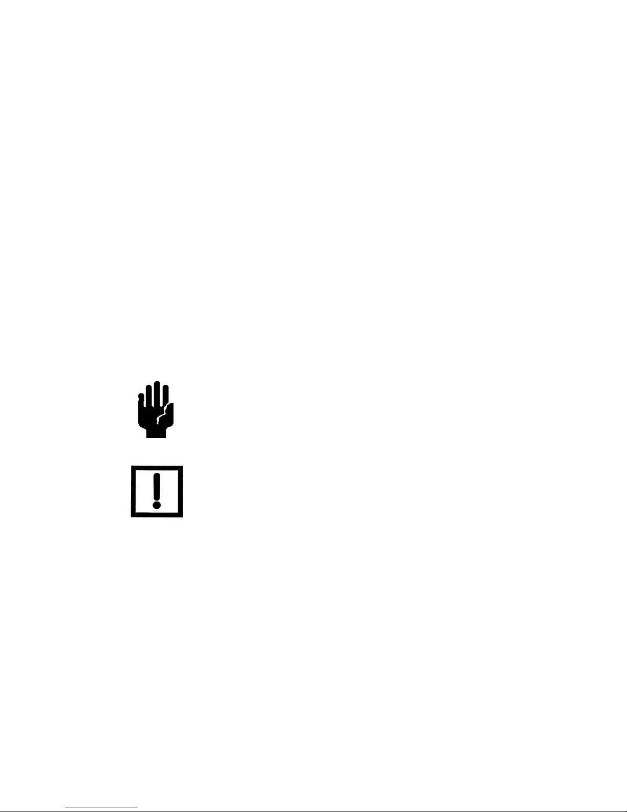
Safety Symbols
Indicates a potentially hazardous situation, which if not
avoided could result in serious injury or death.
Indicates a potentially hazardous situation, which if not
avoided could r
esult in instrument or property damage, or
data loss.
Indicates important facts and conditions.
WARNING
CAUTION
NOTE
1. SVI FF Quick Start
Page 6

© 2017 General Electric Company. All rights reserved.
6 | =GE Oil & Gas
SVI FF Product Safety
The SVI FF digital valve positioner is intended for use with industrial compressed air or, natural
gas systems only.
Ensure that an adequate pressure relief provision is installed when the application of system
supply pressure could cause peripheral equipment to malfunction. Installation must be in accor
-
dance with local and national compressed air and instrumentation codes.
General installation, maintenance or replacement
Products must be installed in compliance with all local and national codes
and standards by qualified personnel using safe site work practices.
Personal Protective Equipment (PPE) must be used per safe site work
practices.
Ensure proper use of fall protection when working at heights, per safe site
work practices. Use appropriate safety equipment and practices to prevent
the dropping of tools or equipment during installation.
Under normal operation, compressed supply gas is vented from the SVI FF to
the surrounding area, and may require additional precautions or specialized
installations.
Intrinsically Safe Installation
Products certified as explosion proof or flame proof equipment or for use in intrinsically safe installations MUST BE:
Installed, put into service, used and maintained in compliance with national
and local regulations and in accordance with the recommendations
contained in the relevant standards concerning potentially explosive
atmospheres.
Used only in situations that comply with the certification conditions shown
in this document and after verification of their compatibility with the zone of
intended use and the permitted maximum ambient temperature.
Installed, put into service and maintained by qualified and competent
professionals who have undergone suitable training for instrumentation
used in areas with potentially explosive atmospheres.
Installations using natural gas are Zone 0 or Div 1
installations.
NOTE
Page 7
© 2017 General Electric Company. All rights reserved.
Masoneilan SVI FF Positioner Quick Start Guide =| 7
WARNING Before using these products with fluids/compressed gases other
than air or for non-industrial applications, consult the factory. This
product is not intended for use in life support systems.
WARNING Under certain operating conditions, the use of damaged
instruments could cause a degradation of the performance of the
system which may lead to personal injury or death.
Installation in poorly ventilated confined areas, with any potential
of gases other than oxygen being present, can lead to a risk of
personnel asphyxiation.
Use only genuine replacement parts which are provided by the manufacturer, to guarantee that
the products comply with the essential safety requirements of the European Directives.
Changes to specifications, structure, and components used may not lead to the revision of this
manual unless such changes affect the function and performance of the product.
Product Numbering
See the ES document in “ES-776 and Declaration of Conformity” on page 17.
Page 8
© 2017 General Electric Company. All rights reserved.
8 | =GE Oil & Gas
Installation and Set Up
The steps necessary to complete the SVI FF installation and software setup are outlined in
Table 1.
Table 1: SVI FF Installation Steps
Step No.
Procedure
1
Attach mounting bracket to the actuator.
2
Install the SVI FF magnetic assembly (rotary valves only).
3
Assemble the SVI FF on the bracket that is mounted to the valve actuator.
4
Connect the pneumatic tubing to the SVI FF.
5
Connect the air supply to the SVI FF.
6
Connect the positioner to the H1 segment by installing the SVI FF wiring.
7
Configure/calibrate using ValVue, the SVI FF DTM or a handheld using the
DD. See“Example Configuration” on page 13 for a general example.
WARNING Failure to adhere to the requirements listed may cause loss of life
and property.
Before installing, using, or carrying out any maintenance tasks
associat
ed with this instrument, READ ALL THE INSTRUCTIONS
CAREFULLY.
Page 9
© 2017 General Electric Company. All rights reserved.
Masoneilan SVI FF Positioner Quick Start Guide =| 9
Pushbuttons and Local Display
Pushbuttons
The local pushbuttons are located behind a hinged cover, directly below the display window. To
open the cover loosen the screw and swing the cover down. Always re-fasten the cover after use
to protect the pushbuttons from environmental contamination.
The three pushbuttons perform the following functions:
Left Button - Marked with *, permits you to select or accept the value or
parameter option currently displayed.
Middle Button - Marked –, permits you to move back through the menu
structure to the previous item in the menu or decrement the value currently
shown in the digital display. When used to decrease a displayed value,
holding the button down causes the value to decrease at a faster rate.
Right Button - Marked +, permits you to move forward through the menu
structure to the next item in the menu, or to increment the value currently
shown in the digital display. When used to increase a displayed value,
holding this button down causes the value to increase at a faster rate.
CAUTION The display is limited to values between 0 and 100. Therefore, the
display may show a value for the actual setpoint that is not valid if
the setpoint is above 100 or below 0.
NOTE When an exclamation point (!) appears in the SVI FF display
window, it indicates that there is instrument status available.
Page 10
© 2017 General Electric Company. All rights reserved.
10 | =GE Oil & Gas
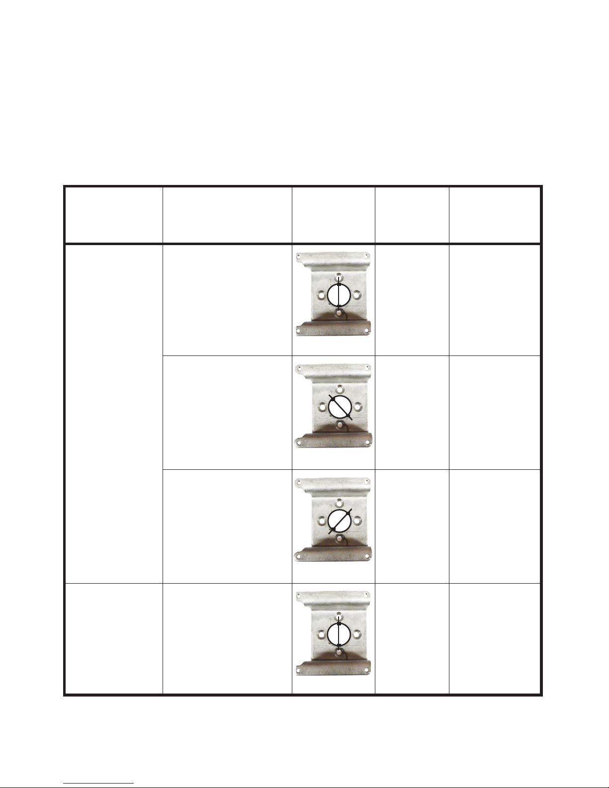
Mounting the SVI FF on Rotary Valves
Travel Sensor Alignment
Table 2 shows the general guidelines for travel sensor alignment. Review the table prior to installing the SVI FF on a rotary valve actuator for proper alignment of the magnet. Alignment is
r
equired for proper Hall sensor operation.
Table 2: Travel Sensor Alignment
Rotary
Mounting
S
ystem
Stroke Direction Magnet
Orientation
Valve
Position
Sensor Counts
(TB: RAW_POSITION)
Rotary <60° Rotation
Clockwise or counterclockwise rotation
(0°)
Closed (0%) 0 +/- 1000
>60° Rotation
Clockwise with increas-
ing setpoint
(-45°)
Full Open
or
Full Closed
-8000 +/- 1500
or
+8000 +/- 1500
>60° Rotation
Counter Clockwise rota-
tion with increasing setpoint
(+45°)
Full Open
or
Full Closed
-8000 +/- 1500
or
+8000 +/- 1500
General Rule for
other configurations
Any amount of rotation
Clock
wise or counter-
clockwise
(0°)
50% Travel
(Mid-Stroke)
0 +/- 1000
Page 11

© 2017 General Electric Company. All rights reserved.
Masoneilan SVI FF Positioner Quick Start Guide =| 11
Mounting the SVI FF on Reciprocating Valves
Table 3: Reciprocating Valve Mounting Hole and Turnbuckle Length
Actuator Size
Masoneilan
Stroke Mounting
Hole
Lever Hole Turnbuckle
Length
6 and 10 0.5 - 0.8"
(12.7 - 20.32 mm)
A A 1.25"
(31.75 mm)
10 0.5 - 0.8"
(12.7 - 20.32 mm)
A A 1.25"
(31.75 mm)
10 >0.8 – 1.5"
(20.32 - 41.5 mm)
B B 1.25"
(31.75 mm)
16 0.5 - 0.8"
(12.7 - 20.32 mm)
B A 2.90"
(73.66 mm)
16 >0.8 – 1.5"
(20.32 - 41.5 mm)
C B 2.90"
(73.66 mm)
16 >1.5 – 2.5"
(41.5 - 63.5 mm)
D C 2.90"
(73.66 mm)
23 0.5 - 0.8"
(12.7 - 20.32 mm)
B A 5.25"
(133.35 mm)
23 >0.8 – 1.5"
(20.32 - 41.5 mm)
C B 5.25"
(133.35 mm)
23 >1.5 – 2.5"
(41.5 - 63.5 mm)
D C 5.25"
(133.35 mm)
Page 12

© 2017 General Electric Company. All rights reserved.
12 | =GE Oil & Gas
Wiring the SVI FF
Figure 1 Connections to Electronics Module (via Terminal Board)
Display
Remote
I/P Connector
Position
Sensor
Configuration Lock
Jumper
9 - 32 V
Foundation*
Discrete Out
Input
Discrete
Shield
(on FF unit
Input Signal
(polarity independent)
Input
Fieldbus
housing)
AI PV 1-5 VDC
(Not used in this release)
Page 13

© 2017 General Electric Company. All rights reserved.
Masoneilan SVI FF Positioner Quick Start Guide =| 13
FF Environment Minimum Settings
The general steps necessary to complete the SVI FF configuration and software setup are outlined in Figure 2.
Step 4: Enter a Device
Address and Device Tag.
Step 2: Set Control Tuning by
choosing Single or Double Acting and
setting tuning type. Autotune is
recommended, Custom requires
entering your values.
Step 1: Set Air Action.
Step 3: Set Characterization Type. Custom requires
entering your values.
Step 5: Run Find Stops and then run Autotune.
Figure 2 Quick Start Configuration
Example Configuration
Step 1: Install the Positioner on the Valve
See “Installation and Set Up” on page 8.
Page 14

© 2017 General Electric Company. All rights reserved.
14 | =GE Oil & Gas
Step 2: Set Tag and Address
Using NI Configurator:
1. Import DD/CFF files.
2. Right-click on the device, select Set Tag, follow the prompts to enter a Tag.
3. Click Set.
4. Right-click on the device, select Set Address, follow the prompts to enter an
Address.
5. Click Set.
Do not navigate to the NI DD folder and copy the
DD file onto itself.
Do not deactivate the Set to OOS mode checkbox.
The block must be in OOS to change the Tag.
If the device is at the temporary address range (248
(0xF8)- 251 (OxFB)), you must set the address
outside of that range.
Do not deactivate the Set to OOS mode checkbox.
The block must be in OOS to change the Address.
CAUTION
CAUTION
CAUTION
CAUTION
Page 15

© 2017 General Electric Company. All rights reserved.
Masoneilan SVI FF Positioner Quick Start Guide =| 15
Step 3: Basic Configuration
This section serves as an example where the AO block and TB block are configured. However,
there are a number of combinations that can be configured. This discussion is valid if the positioner is controlled by the AO block.
1. For the Transducer block set:
ACTUATOR_3.ACT_FAIL_ACTION_1 = either 1. Valve Closed (most common) or
2. Valve Open
ACCESSORY.REMOTE_SENSOR = 0, if remote sensor is not in use (internal
Hall sensor is used)
ACTIVATE_CONTROL_SET to one of:
0: Activate Custom
Control Set
(required for Autotune as well - most
common)
1: Activate Control
Set 1 (Slowest)
2: Activate Control
Set 2
3: Activate Control
Set 3
4: Activate Control
Set 4
5: Activate Control
Set 5 (Fastest)
6: Activate Control
Set 6 (Double Acting
- Slow)
7: Activate Control
Set 7 (Double
Acting- Fast)
CHAR_SELECTION.TYPE to one of:
0. Linear (most
common)
1. Equal Percent-
age (30:1)
2. Equal Percent-
age (50:1)
3. Quick Open
(reversal from Equal
Percentage (50:1))
4. Custom 5. Camflex
Percentage
See Transducer Block P
arameters in the SVI FF instruction manual for further
settings.
2. For the AO block review/set as below:
PV_SCALE.UNIT
INDEX = %
XD_SCALE.UNIT
INDEX = %
CHANNEL = Position
SHED_OPT =
NORMAL SHED
NORMAL RE
TURN
Page 16

© 2017 General Electric Company. All rights reserved.
16 | =GE Oil & Gas
Step 4: Run Find Stops METHOD
Use a configuration tool (DD, SVI FF local pushbuttons or software) to run METHOD.
Step 5: Run Auto Tune METHOD
Use a configuration tool (DD, SVI FF local pushbuttons or software) to run METHOD.
Downloads
To download the complete user manual, DD, SVI FF Advanced DTM and the ValVue Suite trial program, visit: https://www.geoilandgas.com/file-download-search.
Page 17

Masoneilan SVI FF Positioner Quick Start Guide =| 17
© 2017 General Electric Company. All rights reserved
.
Rev
Description
Date
Written by
L. Lu
Jun. 10, 2013
A
Initial Release
ECO-14740
Jun. 10, 2013
Approved
by
R. Belmarsh
Jun. 10, 2013
B
ECO-15557
Aug. 23, 2013
C
ADR-003891
Sept, 24, 2013
ES-776
Rev K
D
ADR-003896
Oct. 1, 2013
E
ADR-003908
Nov 6, 2013
F
ADR-003913
Jan 8, 2014
G
ADR-003926
Feb 24, 2014
H
ADR-003933
May 6, 2014
J
ADR-003987
Dec 16, 2014
K
ADR-004000
Jan 16, 2014
L
PDR ECO0026891
Oct 28, 2016
Page 1 of 14
Copyright 2016. This document and all information herein is the property of Dresser Inc.
ES-776
SPECIAL INSTRUCTIONS FOR INSTALLING Masoneilan SVI FF
POSITIONER IN AREAS WHERE THERE IS A POTENTIAL FOR
EXPLOSIVE GAS ATMOSPHERE OR FLAMMABLE DUST
2. ES-776
Page 18

© 2017 General Electric Company. All rights reserved.
18 | =GE Oil & Gas
GE Oil & Gas
ES-776 Rev L
Page 2 of 14
Copyright 2016. This document and all information herein is the property of Dresser Inc.
Contents
1 INTRODUCTION ........................................................................................................ 3
2 GENERAL REQUIREMENTS ......................................................................................... 4
3 MODEL NUMBER DESCRIPTION OF SVI FF POSITIONER .............................................. 5
4 FLAMEPROOF AND DUST IGNITION PROOF REQUIREMENTS ...................................... 6
General .............................................................................................................. 6
4.1
Cable Glands ..................................................................................................... 6
4.2
Natural gas ......................................................................................................... 6
4.3
Bolting ................................................................................................................ 6
4.4
Carbon Disulphide Exclusion ............................................................................. 6
4.5
Label Cleaning ................................................................................................... 6
4.6
Dust Environment ............................................................................................... 6
4.7
5 INTRINSICALLY SAFE REQUIREMENTS ........................................................................ 7
Div 2 ................................................................................................................... 7
5.1
Category II 1 (Zone 0) ........................................................................................ 7
5.2
Category II 1 (Zone 0) ........................................................................................ 7
5.3
Internal pollution degree 2 and overvoltage category III ..................................... 7
5.4
6 DESCRIPTION OF FLAMEPROOF AND INTRINSICALLY SAFE MARKINGS ....................... 8
7 INTRINSICALLY SAFE INSTALLATION WIRING REQUIREMENTS ................................. 10
8 NOTES FOR INTRINSICALLY SAFE INSTALLATION ..................................................... 11
HAZARDOUS LOCATION ............................................................................... 11
8.1
FIELD WIRING ................................................................................................. 11
8.2
Foundation Fieldbus IN (+) and (-) Terminals .................................................. 11
8.3
PV 1-5VDC (+) and (-) Terminals ..................................................................... 12
8.4
SW (+) and (-) Terminals .................................................................................. 12
8.5
REMOTE (1) and (2) and (3) Terminals ........................................................... 12
8.6
Digital In Terminals .......................................................................................... 12
8.7
Entity Requirement ........................................................................................... 13
8.8
Use in dust atmosphere ................................................................................... 13
8.9
9 REPAIR .................................................................................................................... 13
Main Cover ....................................................................................................... 14
9.1
I/P ..................................................................................................................... 14
9.2
Relay ................................................................................................................ 14
9.3
Electronics........................................................................................................ 14
9.4
Pneumatic Cover .............................................................................................. 14
9.5
Page 19

© 2017 General Electric Company. All rights reserved.
Masoneilan SVI FF Positioner Quick Start Guide =| 19
GE Oil & Gas
ES-776 Rev L
Page 3 of 14
Copyright 2016. This document and all information herein is the property of Dresser Inc.
1
INTRODUCTION
This manual covers the requirements for safe installation, repair, and operation of the SVI FF
positioner as it relates to operation in areas where there is a potential for explosive
atmosphere or flammable dust. Adherence to these requirements assures that the SVI FF
positioner will not cause ignition of the surrounding atmosphere. Hazards related to control
of the process are beyond the scope of this manual.
For mounting instructions on specific valves refer to the mounting instructions supplied with
the mounting kit. Mounting does not affect the suitability of the SVI FF positioner for use in a
potentially hazardous environment.
For language translation assistance contact your local representative or email
svisupport@ge.com.
Pour la langue de traduction aide, contactez votre représentant local ou envoyez un e-mail
svisupport@ge.com.
The SVI FF positioner is manufactured by:
Dresser Inc.
12970 Normandy Blvd.
Jacksonville FL – 32221 – USA
Page 20

© 2017 General Electric Company. All rights reserved.
20 | =GE Oil & Gas
GE Oil & Gas
ES-776 Rev L
Page 4 of 14
Copyright 2016. This document and all information herein is the property of Dresser Inc.
2
GENERAL REQUIREMENTS
Installation and maintenance must be performed only by qualified personnel. Area
Classification, Protection Type, Temperature Class, Gas Group, and Ingress protection must
conform to the data indicated on the label.
Wiring and conduit must conform to all local and national codes governing the installation.
Wiring must be rated for at least 10ºC above the highest expected ambient temperature.
Approved wire seals against ingress of water and dust are required and the NPT fittings
must be sealed with tape or thread sealant in order to meet the highest level of ingress
protection.
Where the protection type depends on wiring glands, the glands must be certified for the
type of protection required.
The metal housing is a die-casting alloy which is predominately aluminum. “X” Marking is on
label.
Before powering the SVI FF positioner:
Verify that the pneumatic and electronic cover screws are tightened. This is
important to maintain the ingress protection level and the integrity of the flameproof
enclosure.
If the Installation is Intrinsically safe, then check that the proper barriers are installed
and the field wiring meets local and national codes for an IS installation. Never install
a device, which was previously installed without an intrinsically safe barrier, in an
intrinsically safe system.
If the pneumatic system is powered by a combustible gas then the installation must
be treated as Zone 0 or DIV I.
In non-incendive installation, check to ensure all electrical connections are made to
approved circuits which meet local and jurisdictional installation codes.
Verify that the markings on the label are consistent with the application.
Verify that the air supply pressure can not exceed the marking on the respective label.
!WARNING!
Failure to adhere to the requirements
listed in this manual may cause loss
of life and property.
Page 21

© 2017 General Electric Company. All rights reserved.
Masoneilan SVI FF Positioner Quick Start Guide =| 21
GE Oil & Gas
ES-776 Rev L
Page 5 of 14
Copyright 2016. This document and all information herein is the property of Dresser Inc.
3
Model Number Description of SVI FF positioner
SVI-abcdefgh Not all combinations are available.
SVI
-
A
Style (2,3,4)
B
Pneumatic
Train
(1,2)
C
Pneumatics
(1,2)
D
Display /
housing
Material
(1,2,3,4)
E
Communications
(F,P)
F
Options
(1)
G
Agency
Approvals
(2)
H
Other Agency
Approvals
(1,2,3,4,5,6)
1
Single
Acting
Standard
Flow
No Display
No Buttons
Aluminum
F= Foundation
Fieldbus
None
North
American
Zone
(FM, FMc)
2
Standard
Diagnostics
Double
Acting
High
Capacity
Display
Buttons
Aluminum
P=Profibus
Unilabeled
(ATEX,
IEC,FMc,
FM)
GOST
3
Advanced
Diagnostics
No Display
No Buttons
Stainless
Steel
KOSHA
4
Display
Buttons
Stainless
Steel
NEPSI
5
INMETRO
6
JIS
7
CCOE
MODEL CODES COVERED BY THIS DOCUMENT:
SVI-abcdefgh, where “a” thru “h” can take on the following values:
a= 1..X. Indicates internal firmware style.
(NOT RELEVANT TO PROTECTION TYPES)
b= 1, 2. Indicates pneumatic train type.
(1 = SINGLE ACTING, 2 = DOUBLE ACTING)
c= 1, 2. Indicates pneumatic flow.
(1 = STANDARD FLOW, 2 = HIGH FLOW)
d= 1, 2, 3, 4. Indicates display type and housing material.
(1 = NO DISPLAY; NO BUTTONS; ALUMINUM)
(2 = DISPLAY; BUTTONS; ALUMINUM)
(3 = NO DISPLAY; NO BUTTONS; STAINLESS STEEL)
(4 = DISPLAY; BUTTONS; STAINLESS STEEL)
e= F, P. Indicates communication protocol.
(F = FOUNDATION FIELDBUS. P = PROFIBUS)
f= 1..X. Indicates options turned on by firmware.
(NOT RELEVANT TO PROTECTION TYPES)
g= 2. Indicates agency approvals.
(UNI-LABEL; ATEX, IEC, FM, FMc)
h= 1. Indicates North American Zone Approvals
2...X. Indicates additional region specific approvals.
Page 22

© 2017 General Electric Company. All rights reserved.
22 | =GE Oil & Gas
GE Oil & Gas
ES-776 Rev L
Page 6 of 14
Copyright 2016. This document and all information herein is the property of Dresser Inc.
(NOT RELEVANT TO PROTECTION TYPES)
4
FLAMEPROOF and DUST IGNITION PROOF REQUIREMENTS
General 4.1
The 1/2 inch NPT fittings must enter the housing at least five full turns.
The cover flange must be clean and free of corrosion products.
Cable Glands 4.2
Certified cable glands are required based on the hazardous area the device is
installed in. That is, the particular cable gland used must have the same
certification as the tick-box checked off on the label.
Natural gas 4.3
Use of a pressurized gas which is ignitable in the presence of air (for example
natural gas) is not allowed as the SVI FF positioner supply pressure in a
flameproof (protection type “d”) installation.
Bolting 4.4
“X” Marking on label- M8 X 1.25-6g cover screws must be supplied by GE. No
substitution allowed. Minimum yield stress to be 296 N/mm^2 (43,000 psi).
Carbon Disulphide Exclusion 4.5
Carbon Disulphide is excluded.
(IEC 60079-1, Clause 15.4.3.2.2., carbon disulphide is excluded for enclosures
with a volume greater than 100cm
3
)
Label Cleaning 4.6
”X” marking on label-Potential Electrostatic Charge Hazard – Use only damp cloth
when cleaning or wiping. Do not use solvent.
Dust Environment
4.7
”X” marking on label-Instruments Installed in dusty hazardous areas. Must be
cleaned regularly to prevent the buildup of dust layers on any surface.
To avoid the risk from electrostatic discharge follow the guidance as detailed in
EN TR50404.
Page 23

© 2017 General Electric Company. All rights reserved.
Masoneilan SVI FF Positioner Quick Start Guide =| 23
GE Oil & Gas
ES-776 Rev L
Page 7 of 14
Copyright 2016. This document and all information herein is the property of Dresser Inc.
For safe operation, use only wet cloth when cleaning or wiping the device.
Cleaning must only be done when local conditions around the device are free of
potentially explosive atmospheres. Do not use dry cloth or any solvents.
5
INTRINSICALLY SAFE REQUIREMENTS
Div 2 5.1
WARNING: EXPLOSION HAZARD – DO NOT DISCONNECT EQUIPMENT UNLESS
POWER HAS BEEN SWITCHED OFF OR THE AREA IS KNOW TO BE NONHAZARDOUS.
Category II 1 (Zone 0)
5.2
For operation in hazardous area category II 1, over-voltage protection of the
electrical connections need to be installed according to EN 60079-14.
For operation in hazardous area category II 1 the ambient temperature needs
to be lowered according to the requirements of EN 1127-1 (reduction factor of
80%). The max. allowed ambient temperature for category 1 inclusive the
requirement of EN1127-1 is:
T6 : Ta = -40°C to +60°C
T5 : Ta = -40°C to +75°C
T4 : Ta = -40°C to +85°C
Category II 1 (Zone 0)
5.3
“X” Marking on label - Since the SVI-abcdefgh (“SVI FF positioner”) contain greater
than 10% aluminum, care must be taken during installation to avoid impacts or
friction that could create an ignition source.
Internal pollution degree 2 and overvoltage category III 5.4
Ensure all covers and seals are correctly installed before putting device into
service.
Page 24

© 2017 General Electric Company. All rights reserved.
24 | =GE Oil & Gas
GE Oil & Gas
ES-776 Rev L
Page 8 of 14
Copyright 2016. This document and all information herein is the property of Dresser Inc.
6
Description of Flameproof and Intrinsically Safe Markings
Applicable models numbers can be found in Section 3.
IN GROUP A INSTALLATIONS CONDUIT SEAL REQUIRED WITHIN 18 INCHES OF
ENCLOSURE
Summary of Agency Markings
Factory Mutual Approvals
Intrinsically Safe & FISCO
Class I Division 1 Groups A,B,C,D T6…T4
Class II,III Division 1 Groups E,F,G
T6…T4
Class I, Zone 0, AEx ia IIC T6…T4 Ga
Class I, Zone 2, AEx ic IIC T6…T4 Gc
Zone 20, AEx ia IIIC T96°C Da
Explosion Proof
Class I, Division 1, Groups A,B,C,D T6…T4
Class I, Zone 1, AEx d mb IIC T6…T4
Class I, Zone 1, IIC T6…T4
Temperature
Classification
T4 Ta = -40°C to 85°C
T5 Ta = -40°C to 75°C
T6 Ta = -40°C to 60°C
Type n Protection
Class I Division 2 Groups A,B,C,D T6…T4
Class II Division 2 Groups F,G T6…T4
Class III Division 1,2 T6...T4
Class I, Zone 2, IIC T6...T4
Dust Ignition Proof
Class II,III Division 1 Groups E,F,G T6...T4
Zone 21, AEx tb IIIC T96°C Db
Zone 22, AEx tc IIIC T96°C Dc
Ingress Protection
IP66; NEMA Type 4X
Canada Approvals (FM Canada Approved)
Intrinsically Safe & FISCO
Class I, Division 1, Groups A,B,C,D
T6…T4
Class II,III Division 1 Groups E,F,G
Class I, Zone 0, Ex ia IIC T6…T4 Ga
Class I, Zone 2, Ex n IIC T6…T4 Gc
Zone 20, Ex ia IIIC T96°C Da
Explosion Proof
Class I Division 1 Groups B,C,D
T6…T4
Class I, Zone 1, Ex
d m
IIB+H2
T6…T4
Class I, Zone 1, IIB+H2
T6…T4
Temperature
Classification
T4 Ta = -40°C to 85°C
T5 Ta = -40°C to 75°C
T6 Ta = -40°C to 60°C
Type n Protection
Class I Division 2 Groups A,B,C,D T6…T4
Class II Division 2 Groups F,G
Class III Division 1,2
Dust Ignition Proof
Class II, Division 1 Groups E,F,G
Class III, Division 1,2
Ingress Protection
IP66, Type 4X
Page 25

© 2017 General Electric Company. All rights reserved.
Masoneilan SVI FF Positioner Quick Start Guide =| 25
GE Oil & Gas
ES-776 Rev L
Page 9 of 14
Copyright 2016. This document and all information herein is the property of Dresser Inc.
ATEX Approvals
FM14ATEX0014X
FM14ATEX0015X
Intrinsically Safe
II 1G Ex ia IIC T6…T4 Ga
II 1D Ex ia IIIC T96°C Da
II 3G Ex ic IIC T6…T4 Gc
Flame Proof
II 2G Ex
d mb
IIC
T6…T4 Gb
Temperature Classification
T4 Ta = -40°C to 85°C
T5 Ta = -40°C to 75°C
T6 Ta = -40°C to 60°C
Dust Ignitionproof
II 2D Ex tb IIIC T96°C Db
II 3D Ex tc IIIC T96°C Dc
Ingress Protection
IP66
IECEx Approvals
IECEx FMG 14.0007X
Intrinsically Safe
Ex ia IIC T6…T4 Ga
Ex ia IIIC T96°C Da
Ex ic IIC T6…T4 Gc
Flame Proof
Ex
d mb
IIC
T6…T4 Gb
Temperature Classification
T4 Ta = -40°C to 85°C
T5 Ta = -40°C to 75°C
T6 Ta = -40°C to 60°C
Dust Ignitionproof
Ex tb IIIC T96°C Db
Ex tc IIIC T96°C Dc
Ingress Protection
IP66
Operating Ranges
Temp: -40°C ≤ Ta ≤ 85°C
Voltage: 9 to 32V DC
Pressure: 150 psig (1.03MPa)
Current: 18.3 mA (Max)
Notes Related to Explosionproof Rating
1) “DO NOT OPEN EVEN WHEN ISOLATED WHEN EXPLOSIVE ATMOSPHERES ARE
PRESENT”
Notes Related to Intrinsic Safety
1) “INSTALL Per ES-776”
2) “Supply Connection Wiring Rated for 10ºC Above Max Ambient”
3) “
PERMANENTLY MARK THE PROTECTION TYPE CHOSEN. ONCE THE TYPE HAS
BEEN MARKED, IT CAN NOT BE CHANGED”
Model Code:
“SVI-abcdefgh” (see section 3 above for explanation)
Serial Number:
“SN-nnyywwnnnn”
Page 26

© 2017 General Electric Company. All rights reserved.
26 | =GE Oil & Gas
GE Oil & Gas
ES-776 Rev L
Page 10 of 14
Copyright 2016. This document and all information herein is the property of Dresser Inc.
7
Intrinsically Safe Installation Wiring Requirements
Optional
Intrinsically Safe
Process Variable
Trnsmitter
NON- HAZARDOUS LOCATION- UNSPECIFIED EXCEPT
THAT BARRIERS MUST NOT BE SUPPLIED FROM NOR
CONTAIN UNDER NORMAL OR ABNORMAL CONDITIONS A
SOURCE OF POTENTIAL WITH RESPECT TO EARTH IN
EXCESS OF 250 VOLTS RMS OR250 VOLTS DC
HAZARDOUS LOCATION
SEE8.1 ,8.2
1
2
4
3
SVI FF Positioner
SW 1 (DO)
-
+
Equi- Potential
Optional Field
Load
Shunt Zener Diode Safety Barrier
Controller Output Type (See 8.3)
24 VDC from DCS
To DCS DI
Shunt Zener Diode Safety
Barrier Switch Type Barrier (See 8.5)
Cable Shield
SVI FF Remote
Mount
- - -
- - -
Remote
1
2
1 to 5 Volts to
control system
4
3
AI_PV 1- 5VD C
-
+
Shunt Zener Diode Safety
Barrier Switch Type Barrier
(See8.4)
1
2
4
3
Shunt Zener Diode Safety Barrier-
Controller Output Type (See 8.4)
-
+
Transmitter
24 VDC from
Control System
See Note8.6
DI
+
-
Simple Passive
Apparatus
(Switch, relay)
+
-
Foundation
Fie busdl
4
3 1
2
(See
8. )
Optional Hand Held
8
Communicator
Foundation Field bus
Set Point from
Control system
Optional Hand Held
Communicator
Each intrinsically safe cable must include a grounded shield or be run in a separate metal
conduit.
Page 27

© 2017 General Electric Company. All rights reserved.
Masoneilan SVI FF Positioner Quick Start Guide =| 27
GE Oil & Gas
ES-776 Rev L
Page 11 of 14
Copyright 2016. This document and all information herein is the property of Dresser Inc.
8
Notes for Intrinsically Safe Installation
HAZARDOUS LOCATION 8.1
Refer to the device label for the description of the environment in which the
device may be installed.
FIELD WIRING 8.2
Intrinsically Safe wiring must be made with grounded shielded cable or installed
in grounded metal conduit. The electrical circuit in the hazardous area must be
capable of withstanding an A.C. test voltage of 500 volts R.M.S. to earth or frame
of the apparatus for 1 minute. Installation must be in accordance with GE
guidelines. The installation including the barrier earthing requirements must
comply with the installation requirements of the country of use. For Division
1/Zone 0 installations, the configuration of associated apparutus shall be FM
Approved under Entity/FISCO Concept.
FM Approvals requirements (USA): ANSI/ISA RP12.6 (Installation of Intrinsically
Safe Systems for Hazardous (Classified) Locations) and the National Electrical
Code, ANSI/NFPA 70. Division 2 installations must be installed per the National
Electrical Code, ANSI/NFPA 70.
FMc requirements (Canada): Canadian Electrical Code Part 1. Division 2
installations must be installed per the Canadian Electrical Code Division 2 Wiring
Methods.
ATEX requirements (EU): Intrinsically safe installations must be installed per
EN60079-10 and EN60079-14 as they apply to the specific category.
Foundation Fieldbus IN (+) and (-) Terminals 8.3
These terminals power the SVI FF positioner, and are not polarity sensitive. The
FF interface shall conform to the physical layer reqiurements of IEC60079-11,
IEC61158-2, and FF-816.
FISCO I.S. Model
Parameters
Entity Model
Parameters
Max. Input Voltage
Ui
17.5V
24V
Max. Input Current
Ii
380mA
250mA
Max. Input Power
Pi
5.32W
1.2W
Max. Internal Capacitance
Ci
1nF
1nF
Max. Internal Inductivity
Li
1μH
1μH
Page 28

© 2017 General Electric Company. All rights reserved.
28 | =GE Oil & Gas
GE Oil & Gas
ES-776 Rev L
Page 12 of 14
Copyright 2016. This document and all information herein is the property of Dresser Inc.
PV 1-5VDC (+) and (-) Terminals 8.4
The Process Transmitter and the SVI FF positioner’s PV Input are both barrier
protected. The transmitter 4 to 20 mA signal is converted to 1 to 5 Volts at the
Transmitter barrier. The 1 to 5 volt signal is monitored by the DCS and used by
the SVI FF positioner for the embedded process controller. The sense resistor
may be in the barrier or in the Digital Control System.
The Process Transmitter must be approved for use with the Process Transmitter
Barrier. An example of a suitable barrier is MTL 788 or 788R An example of the PV
INPUT barrier is MTL 728.
Entity Parameters of the PV terminals:
Vmax = 30 Vdc; Imax = 125 mA; Ci = 1 nF; Li = 0 uH; Pmax = 900 mW
SW (+) and (-) Terminals 8.5
There is one solid state switch contact output on the SVI FF positioner. It is
labeled SW. The switch is polarity sensitive – that is, conventional current flows
INTO the plus terminal.
Entity parameters are:
Vmax = 30 Vdc Imax = 125 mA Ci = 4 nF Li = 10 uH
Pmax = 500 mW
REMOTE (1) and (2) and (3) Terminals
8.6
The REMOTE terminals deliver reference Voltage to an optional remote position
sensing potentiometer. Current, Voltage, and Power are limited by the SVI FF
positioner.
The REMOTE terminals entity parameters are the parameters of the 4 to 20 mA
INPUT barrier.
The SVI-II REMOTE MOUNT is approved for use as a remote position sensing
device with the SVI FF positioner.
Entity parameters of the Remote Terminals are:
Uo/Voc = 6.5 Volts Io/Isc = 9.6 mA Ca = 22 uF La = 300 mH
Connect only to suitable potentiometer.
Digital In Terminals
8.7
The Digital In terminal is suitable for direct connection to a passive switch.
Entity Parameters are:
Uo/Voc = 5.35 Volts Io/Isc = 50.6 mA Ca = 1.25 uF La = 2 mH
Connect only to passive dry contact simple apparatus.
Page 29

© 2017 General Electric Company. All rights reserved.
Masoneilan SVI FF Positioner Quick Start Guide =| 29
GE Oil & Gas
ES-776 Rev L
Page 13 of 14
Copyright 2016. This document and all information herein is the property of Dresser Inc.
Entity Requirement
8.8
Cable capacitance and inductance plus the I.S. apparatus unprotected
capacitance (Ci) and inductance (Li) must not exceed the allowed capacitance
(Ca) and inductance (La) indicated on the associated apparatus. If the optional
Hand Held Communicator is used on the Hazardous Area side of the barrier, then
the capacity and inductance of the communicator must be added and the
communicator must be agency approved for use in the hazardous area. Also,
the current output of the Hand Held Communicator must be included in the
current output of the associated equipment.
For North American installations, the barriers may be active or passive and from
any FM Approved manufacturer as long as the barriers comply with the listed
entity parameters.
For European installations, the barriers may be active or passive and from any
certified manufacturer as long as the barriers comply with the listed entity
parameters and are installed per the guidelines of EN60079-14.
For other international installations, the barriers may be active or passive and
from any certified manufacturer as long as the barriers comply with the listed
entity parameters and are installed per the guidelines of IEC60079-14.
If the electrical parameters of the cable used are unknown, the following values
may be used: Capacitance – 197pF/m (60 pF/ft), Inductance – 0.66 μH/m (0.20
μH/ft).
Use in dust atmosphere 8.9
Dust-tight conduit seal must be used when installed in dust hazard
environments.
9
REPAIR
WARNING: EXPLOSION HAZARD – SUBSTITUTION OF COMPONENTS MAY IMPAIR SUITABILITY
FOR USE IN A HAZARDOUS LOCATION.
Only qualified service personnel are permitted to make repairs on the SVI FF positioner.
Replace ONLY with genuine GE parts.
Use only cover bolts of Autenitic Grade A2 Class 70 or Grade A4 Class 70, supplied by the
manufacturer.
Consult the manufacturer for dimensional information on the flameproof joints for repair.
Only parts supplied by GE are permitted. This includes not only the major assemblies but
also mounting screws and “O” rings. No substitutions with non-GE parts are permitted.
Page 30

© 2017 General Electric Company. All rights reserved.
30 | =GE Oil & Gas
GE Oil & Gas
ES-776 Rev L
Page 14 of 14
Copyright 2016. This document and all information herein is the property of Dresser Inc.
Detailed replacement procedures are described in the SVI FF Quick Start Guide. The
following summary assures the safe operation of the SVI FF positioner.
For assistance, contact the nearest sales office, your local representative or email
svisupport@ge.com. Visit our web page at www.ge-energy.com/valves
Main Cover 9.1
Make sure that:
The gasket is seated in the groove in the housing flange.
No wires or retaining cable can be trapped under the cover flange.
The flange area is not corroded and the surface is not scarred.
The four cover bolts are securely tightened.
Secure the four cover bolts by applying a torque of 55±5 in-lbs.
I/P 9.2
Make sure that:
The wire is not damaged when feeding it through the housing.
A single “O” ring is in place on the wire-sleeve and is not damaged.
The four retaining screws are snug.
Inserting the wire sleeve through the housing does not require force.
Relay
9.3
Make sure that:
The five “O” rings are seated in the base of the relay and are not damaged. Note
that the five “O” rings may be 5 individual parts, or 5 “O”rings ganged together as
1 part.
The mounting screws are snug.
Electronics 9.4
Make sure that:
The 4 “O” rings are seated on the base of the electronics assembly and are not
damaged.
The four retaining screws are snug,
Pneumatic Cover 9.5
Make sure that:
The gasket is seated in the groove.
The retaining screws are snug.
Page 31

Page 32

DIRECT SALES OFFICE LOCATIONS
AUSTRALIA
Brisbane
Phone: +61-7-3001-4319
Fax: 88+61-7-3001-4399
ITALY
Phone: +39-081-7892-111
Fax: 88+39-081-7892-208
SOUTH AFRICA
Phone: +27-11-452-1550
Fax: 88+27-11-452-6542
Perth
Phone: +61-8-6595-7018
Fax: 88+61-8-6595-7299
JAPAN
Tokyo
Phone: +81-03-6871-9008
Fax: ==+81-03-6890-4620
SOUTH and CENTRAL
AMERICA AND THE CARIBBEAN
Phone: +55-12-2134-1201
Fax: 88+55-12-2134-1238
Melbourne
Phone: +61-3-8807-6002
Fax: 88+61-3-8807-6577
KOREA
Phone: +82-2-2274-0748
Fax: 88+82-2-2274-0794
SPAIN
Phone: +34-93-652-6430
Fax: 88+34-93-652-6444
BELGIUM
Phone: +32-2-344-0970
Fax: 88+32-2-344-1123
MALAYSIA
Phone: +60-3-2161-0322
Fax: 88+60-3-2163-6312
UNITED ARAB EMIRATES
Phone: +971-4-8991-777
Fax: 88+971-4-8991-778
BRAZIL
Phone: +55-19-2104-6900
MEXICO
Phone: +52-55-3640-5060
UNITED KINGDOM
Bracknell
Phone: +44-1344-460-500
Fax: 88+44-1344-460-537
CHINA
Phone: +86-10-5689-3600
Fax: 88+86-10-5689-3800
THE NETHERLANDS
Phone: +31-15-3808666
Fax: 88+31-18-1641438
Skelmersdale
Phone: +44-1695-526-00
Fax: 88+44-1695-526-01
FRANCE
Courbevoie
Phone: +33-1-4904-9000
Fax: 88+33-1-4904-9010
RUSSIA
Veliky Novgorod
Phone: +7-8162-55-7898
Fax: 88+7-8162-55-7921
UNITED STATES
Jacksonville, Florida
Phone: +1-904-570-3409
GERMANY
Ratingen
Phone: +49-2102-108-0
Fax: 88+49-2102-108-111
Moscow
Phone: +7 495-585-1276
Fax: 88+7 495-585-1279
Corpus Christi, Texas
Phone: +1-361-881-8182
Fax: 88+1-361-881-8246
INDIA
Mumbai
Phone: +91-22-8354790
Fax: 88+91-22-8354791
SAUDI ARABIA
Phone: +966-3-341-0278
Fax: 88+966-3-341-7624
Deer Park, Texas
Phone: +1-281-884-1000
Fax: 88+1-281-884-1010
New Delhi
Phone: +91-11-2-6164175
Fax: 88+91-11-5-1659635
SINGAPORE
Phone: +65-6861-6100
Fax: 88+65-6861-7172
Houston, Texas
Phone: +1-281-671-1640
Fax: 88+1-281-671-1735
Visit us online at: www.geoilandgas.com/valves
Other company names and product names used in this document are the
registered trademarks or trademarks of their respective owners.
© 2017 General Electric Company. All rights reserved.
GEA31030D 02/2017
 Loading...