

Page 1
Installation Guide
LuminationTM LED Luminaires
Suspended LED Fixture
(Series EP24)
Features
• Long life (50,000 hour rated life)
• 5 year warranty
• Dry location rated
BEFORE YOU BEGIN
Read these instructions completely and carefully.
WARNING/AVERTISSEMENT
RISK OF ELECTRIC SHOCK
• Turn power off before inspection, installation or removal.
• Properly ground electrical enclosure.
RISK OF FIRE
• Follow all NEC and local codes.
• Use only UL or IEC approved wire for input/output
connections. Minimum size 18 AWG (0.82mm2).
Save These Instructions
Use only in the manner intended by the manufacturer. If you have any questions, contact the manufacturer.
Each luminaire is to be used with remote driver kit, model no. EP-DKIT400.
Wiring to be performed by qualified electrician only.
RISQUES DE DÉCHARGES ÉLECTRIQUES
• Coupez l’alimentation avant d’’inspecter, installer ou déplacer le luminaire.
• Assurez-vous de correctement mettre à la terre le boîtier d’alimentation
électrique.
RISQUES D’INCENDIE
• Respectez tous les codes NEC et codes locaux.
• N’utilisez que des fils approuvés par UL ou IEC pour les entrées/sorties de
connexion. Taille minimum 18 AWG (0.82mm2).
Page 2
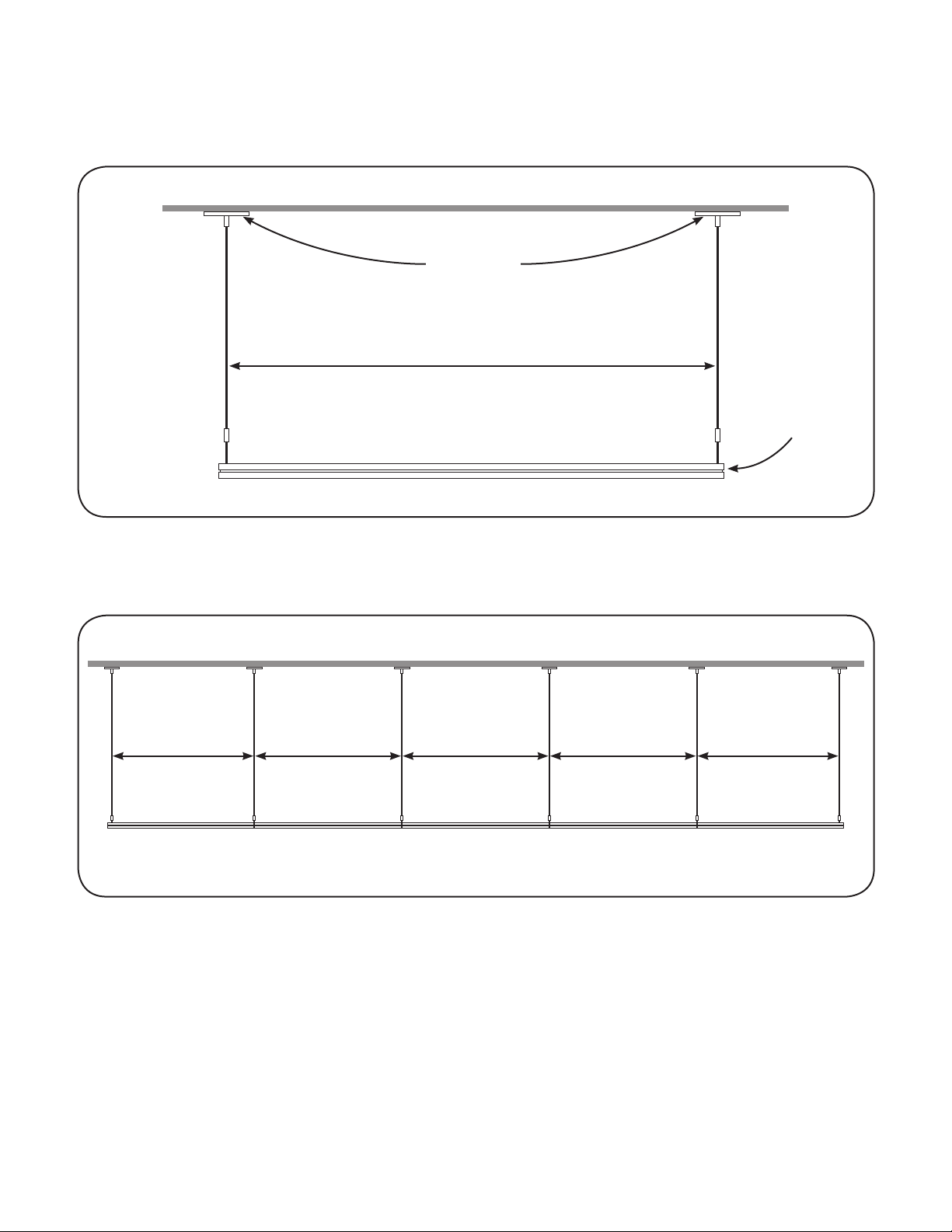
Define Distance Between Canopy Sets
Single unit installation scenario:
Canopy set
1179mm (46.4 in.)
(distance between canopy sets)
Luminaire
Multiple units in series installation scenario:
1193mm (47 in.) 1207mm (47.5 in.) 1207mm (47.5 in.) 1207mm (47.5 in.) 1193mm (47 in.)
1st luminaire 2nd luminaire 3rd luminaire 4th luminaire 5th luminaire
Distance between canopy sets for left and right luminaires = 1193mm (47 in.)
Distance between canopy sets for luminaires in the middle = 1207mm (47.5 in.)
Example: To install five units in series, the distance between canopy sets for the 1st (left) and 5th (right) luminaire is
1193mm (47 in.), and the distance between canopy sets for the 2nd, 3rd and 4th (middle) luminaires is 1207mm (47.5 in.)
Page 3

Unit Installation
Carefully unpack unit from its packaging. Properly
1
inspect for defects before installing. Wear work
gloves to prevent dirt and oil from being
transferred to the luminaire.
To driver enclosure
Canopy
(electrical)
To driver enclosure
Attach crossbar to junction box in ceiling with two
2
Junction box in ceiling
Crossbar
1/4 inch screws. Repeat on other side.
Stud
Strain relief
bushing
Wires from luminaire
Connect the black (line) and white (neutral) wires
3
from the luminaire to the matching-colored
wires from the driver enclosure. Connect both
green wires to the grounding screw. Refer to the
EP-DKIT400UV and EP-DKIT400UD LED Driver
Installation Instructions for more information.
Squeeze tip to adjust
Cable coupler
Suspension cable
Fit canopy over stud of crossbar, then screw
4
cable coupler onto stud.
Tie wrap
To adjust height and to level a fixture, squeeze
5
the tip of the gripper and pull the suspension
cable to the desired height. Clip the cable with
cable cutters to finish the appearance.
Optional: For an improved appearance, electrical
6
wire can be tie-wrapped to the suspension wire.
Page 4

Optional Mounting Method - Connecting Suspended Fixtures in Series
Canopy set without power cable
Canopy sets with power cable
For multiple units installed in series, all canopy sets will have a power cable except the last canopy.
1
Disconnect
suspension wire
1st luminaire
On the 1st luminaire, disconnect the right-side
2
suspension wire and “Y” shape suspension wire.
Then on the 2nd luminaire, disassemble the leftside “Y” shape suspension wire (this one will not
be used).
Remove “Y” shape wires
2nd luminaire
“Y” shape
suspension wire
Attach a bracket to each end of the “Y” shape
3
suspension wire using washer, spring washer
and M8 nuts. Screw torque should be between
15.3±0.8kg f.
Squeeze tip to adjust
Bracket
Join 1st and 2nd luminaires together by fastening
4
the brackets on the modified “Y” shape
suspension wire from Step 9. Fasten brackets
using four
M8 screws. Screw torque should be between 15.3
±0.8kg f.
Reattach suspension wire to “Y” shape suspension
5
wire. To adjust height and to level a fixture,
squeeze the tip of the gripper and pull the
suspension cable to the desired height. Clip the
cable with cable cutters to finish the appearance.
Page 5

Maximum Driver Remote Mounting Distance
Supply Wire Gauge Wire Length*
18 AWG (0.82 mm2) 59.0 ft. (18 m)
16 AWG (1.31 mm2) 98.4 ft. (30 m)
14 AWG (2.08 mm2) 154.2 ft. (47 m)
12 AWG (3.31 mm2) 249.3 ft. (76 m)
* Includes xture’s 6.6 ft. (2.0 m) power cord
Specifications
Input Voltage (VAC) 120 – 277V
Input Power (W) 55W
Input Frequency (Hz) 50/60 Hz
Power Factor > 0.9
THD < 20%
Control 0-10V & DALI
Ceilings Cable Suspension System
Warranty 5 years
Dimensions 47.5 in. x 11.8 in. x 1.38 in. (1206 mm x 299 mm x 35 mm)
Light Fixture Weight 14.3 lbs. (6.5 kg)
Environmental Operating Temperature Range -10°C to +40°C
Environmental Humidity (non-condensing) 20 to 80% Non-condensing, dry location rated
Environmental Storage Temperature Range -40°C to +60°C
Conforms to the following standards:
This device complies with Part 15 of the FCC Rules. Operation is subject to the following two conditions: (1) This device may not cause
harmful interference, and (2) this device must accept any interference received, including interference that may cause undesired operation.
CAN ICES-005 (A) / NMB-005 (A)
Note: This equipment has been tested and found to comply with the limits for a Class A digital device, pursuant to part 15 of the FCC
Rules. These limits are designed to provide reasonable protection against harmful interference when the equipment is operated in a
commercial environment. This equipment generates, uses, and can radiate radio frequency energy and, if not installed and used in
accordance with the instruction manual, may cause harmful interference to radio communications. Operation of this equipment in a
residential area is likely to cause harmful interference in which case the user will be required to correct the interference at his own expense.
www.gecurrent.com
GE and the GE Monogram are trademarks of the General Electric Company and are used under license. Information
provided is subject to change without notice. All values are design or typical values when measured under laboratory
conditions, and GE makes no warranty or guarantee, express or implied, that such performance will be obtained
under end-use conditions. © 2019 GE Current, a Daintree company
IND025-191217
 Loading...