

Page 1
GE Healthcare
Lullaby™
LED Phototherapy System
Operation and Maintenance Manual
Operation and Maintenance Manual
English
2051539-001
Rev F
© 2011 by General Electric Company. All
rights reserved.
Page 2

© 2011 General Electric Company
All rights reserved. General Electric Company reserves the right to make changes in
specications and features shown herein, or discontinue the product described at any
time without notice or obligation. Contact your GE Representative for the most current
information. Lullaby is a trademark owned by Datex-Ohmeda, Inc. GE and GE Monogram
are trademarks of General Electric Company. All other company and product names
mentioned may be trademarks of the companies with which they are associated.
Page 3

Table of Contents
About this Manual......................................................................................................5
Chapter 1: Safety........................................................................................................9
Chapter 2: Product Description.............................................................................11
2.1 Features......................................................................................................................................11
2.3 Controls, Indicators, Mechanical controls...................................................................12
Chapter 3: Operating Procedure............................................................................15
3.1 Operating Instructions.........................................................................................................15
3.2 Checking equipment before use.....................................................................................15
3.3 Preparing an Infant for phototherapy..........................................................................15
3.4 Basic Operating Procedure................................................................................................16
3.5 Tilting the Lamp enclosure.................................................................................................19
3.6 Using with other devices.....................................................................................................19
3.7 Using Lamp enclosure in detached condition...........................................................21
Chapter 4: Troubleshooting....................................................................................23
Chapter 5: Cleaning and Maintaining...................................................................29
5.1 Cleaning ....................................................................................................................................29
5.2 Maintaining................................................................................................................................29
Appendix A: Specifications......................................................................................31
Appendix B: Technical Reference...........................................................................33
B.1 Effective Surface Area.........................................................................................................33
B.2 Service Maintenance............................................................................................................35
B.3 Part Replacement..................................................................................................................35
Appendix C: Electromagnetic Compatibility (EMC)............................................37
C.1 Electromagnetic Emission..................................................................................................37
C.2 CE Marking Information......................................................................................................39
C.3 Recommendation.............................................................................................40
Warranty...................................................................................................................41
© 2011 by General Electric Company. All rights reserved. 2051539-001 Rev F 3
Page 4

Table of Contents
This page is left blank intentionally.
4 2051539-001 Rev F © 2011 by General Electric Company. All rights reserved.
Page 5
About this Manual
Scope
This manual provides a comprehensive description of the components of Lullaby LED
Phototherapy System and its operation and maintenance details.
Indications for Use
The Lullaby LED Phototherapy System is used for the treatment of indirect hyperbilirubinemia in term and pre-term infants, in a hospital environment – NICUs, PICUs and
Well-baby Nurseries - administered by trained, professional medical sta, on the order of a
licensed medical practitioner.
The Lullaby LED PT system is intended for use under the direct supervision of a licensed
healthcare practitioner.
The Lullaby LED PT system device is not intended to be operated in mobile vehicles
including ambulances or other vehicles associated with health care facilities.
Intended Users
This device should only be operated by health care providers who are trained in its
operation and familiar with the risks of this type of device.
Purpose
The manual provides a complete guide on how to install, use and maintain the Lullaby LED
Phototherapy System. Detailed technical information has been enumerated for the benet
of the user to facilitate correct and eective application of the device.
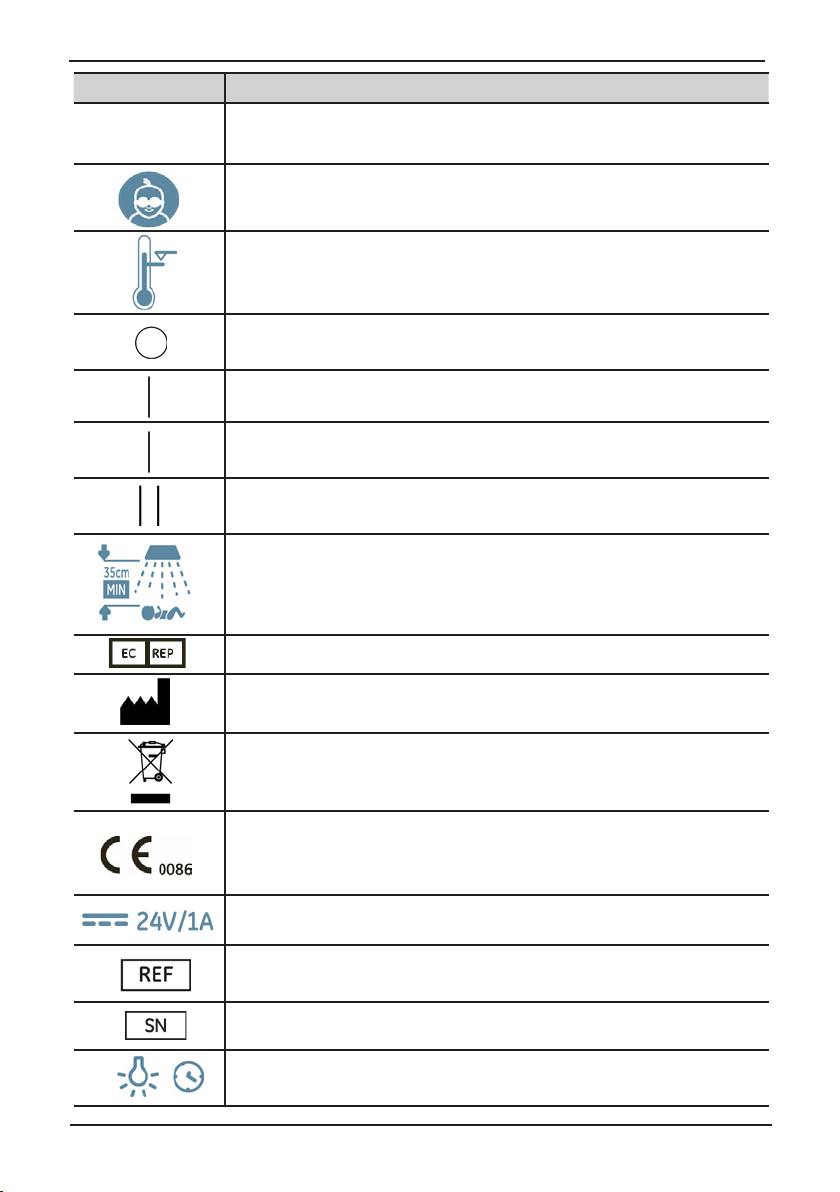
Symbol Denition
The following table describes the symbols and its inferences.
Symbol Description
This symbol denotes “Caution, read accompanying documents.” This
applies also to when the Caution symbol appears on an equipment
q .
WARNING A WARNING statement is used when the possibility of injury exists.
© 2011 by General Electric Company. All rights reserved. 2051539-001 Rev F 5
label. It means additional information is found in the accompanying
documents.
A General Warning statement is used to inform the users of the
equipment on possible risk or injury.
Page 6
About this Manual
Symbol Description
NOTE A NOTE provides additional information to clarify a point in the text.
Cover the patient’s eyes while administering phototherapy.
Over Temperature Cut-o Indicator
Power OFF
Power ON
Low Irradiance
High Irradiance
Maintain 35 cm minimum distance between light source and infant
European Union Representative
Manufacturer—The symbol shall be accompanied by the name and
the address of the manufacturer.
WEEE Symbol
CE Mark
DC Current
Part number of Lullaby LED Phototherapy System
Serial Number of Lullaby LED Phototherapy System
Lamp life timer
6 2051539-001 Rev F © 2011 by General Electric Company. All rights reserved.
Page 7
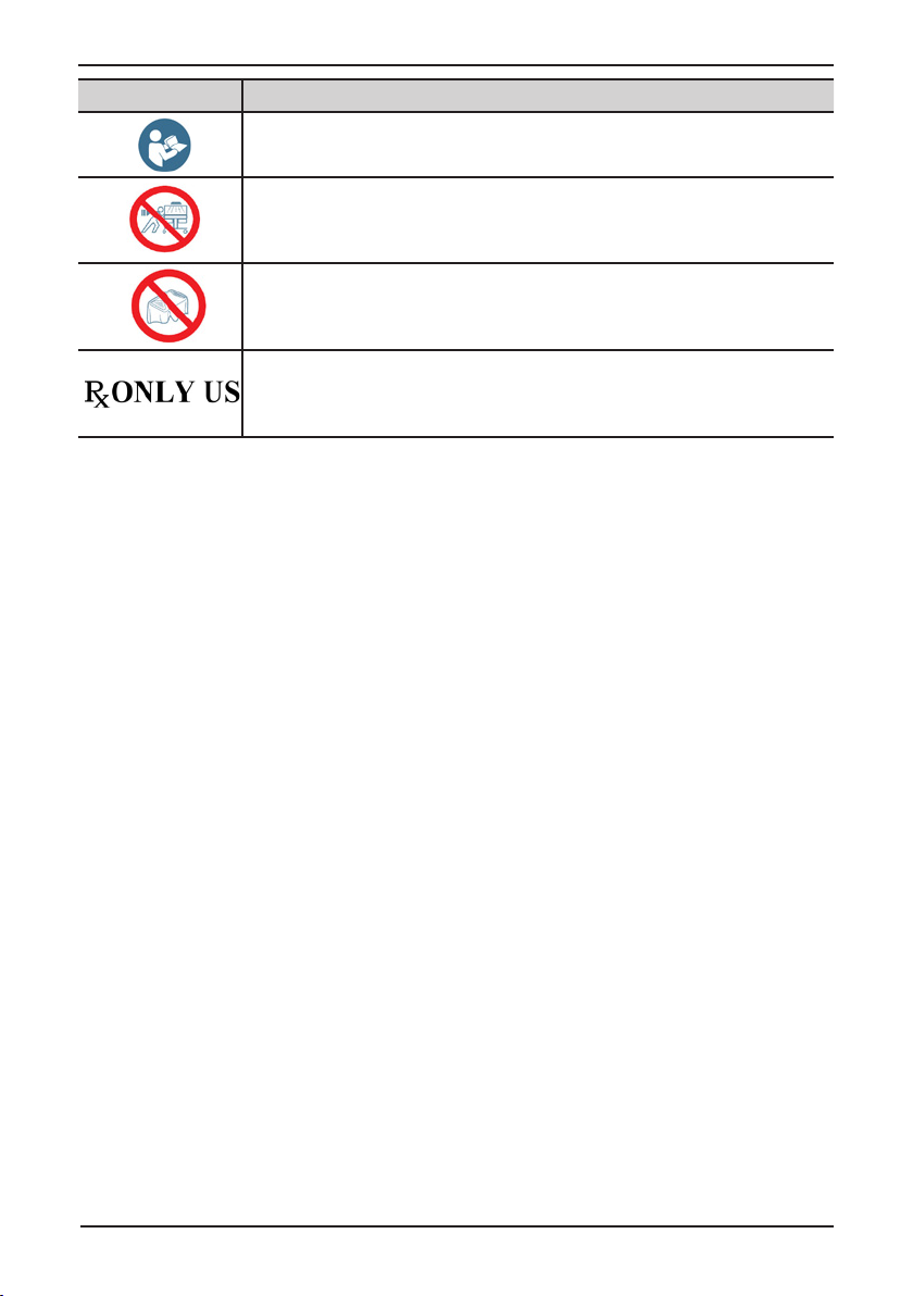
Symbol Description
Refer to instruction manual/booklet
Do not move the incubator with the device on it.
Do not cover the vent
Prescription Device Label for United States.
About this Manual
© 2011 by General Electric Company. All rights reserved. 2051539-001 Rev F 7
Page 8

About this Manual
This page is left blank intentionally.
8 2051539-001 Rev F © 2011 by General Electric Company. All rights reserved.
Page 9

Chapter 1: Safety
It is important to know and understand the safety measure to be followed before using
the phototherapy device. The precautions mentioned below are to prevent possible risk of
injury to the patient or the operator and ensure correct usage of the equipment.
WARNINGS
• Possible Risks: All phototherapy methods have possible risks including, but not limited
to, bronze baby syndrome, diarrhea, hyper-pigmentation, minor erythema, skin
reddening, skin blistering, and potential retinal damage. Monitor the patient closely for
signs of these conditions during phototherapy.
• Photo Isomers: Bilirubin photo isomers might cause toxic eects.
• Porphyrins: Porphyrins are the by-products of the photochemical break down of
the bilirubin molecule. In some cases, exposure of porphyrins to phototherapy could
result in a localized reddening of the patient's skin. Therefore, skin assessment is
recommended with all types of phototherapy per hospital policy.
• Photosensitive Drugs: The light generated can degrade photosensitive medications.
Do not place or store any drugs near or in the illuminated area.
• Dehydration and Insensible Water Loss: The radiant energy from phototherapy lights
can increase a patient's insensible water loss. Take appropriate measures to maintain
the patient's uid balance while administering phototherapy.
• Skin Temperature: Phototherapy light may aect the temperature in thermoregulation
devices (incubator, radiant warmers or heated mattresses) and could result in raising
the patient's body temperature when the device is in use. It is recommended to use
an incubator, warmer or bassinet in skin controlled (servo) mode. Always monitor the
patient's temperature to avoid temperature uctuations during phototherapy as per
hospital policy.
• Reective Foils: Using reective foils to increase the ecacy of phototherapy may
cause hazardous increase in patient’s body temperature.
• Eye Protection: Do not look directly into the lamps. During treatment, always protect
the patient’s eyes with protective eyewear. Periodically, as per hospital protocol, verify
that the patient’s eyes are protected and free of irritation.
• Operator Safety: Users may experience headache, nausea or mild vertigo if the user
remains in the irradiated area for a prolonged period of time. Using the Lullaby LED
Phototherapy System in a well-lit area or wearing glasses with yellow lenses can
alleviate potential eects.
• Regular monitoring: During treatment it is recommended to follow the measures as
specied in the following guidelines:
• Measure the patient’s bilirubin level periodically during treatment per hospital
guidelines.
• Turn o the light when checking the patient’s condition and skin color.
• Follow standard procedures for monitoring patient temperature and uid status.
• Verify that the patient’s eyes are protected and free of irritation as per hospital
guidelines.
• Maintain a distance of 35 cm between the light unit and the patient for optimal
light intensity.
© 2011 by General Electric Company. All rights reserved. 2051539-001 Rev F 9
Page 10

Safety
• Adjusting Height: Do not adjust the height of the equipment with the patient directly
under the unit. Secure the light unit in position before placing the patient under the
device for therapy.
• Do not place the device in the path of any elevating bed.
• Hot surface: The lens surface on the lamp enclosure assembly could be as hot as 70
°C during operation. Do not touch the lens when the lamps are in ON condition.
The LED Phototherapy system , as with any electrical equipment must be must be handled
with care to avoid damage to the equipment. Follow the below mentioned precautions with
regard to the device.
q CAUTION
• Following EMC Regulation: Medical Electrical Equipment needs to be installed and
put into service strictly according to the EMC information provided in this manual.
• Portable and mobile RF communications equipment can aect Medical Electrical
Equipment.
• Environment: When using the Lullaby LED Phototherapy System adjacent to other
equipment, it is important to verify normal operation in the conguration in which
it is used.
• Do not use the Lullaby LED Phototherapy System in the presence of ammable
anesthetics or gases to prevent any possibility of explosion under these
conditions.
• When using the Lullaby LED Phototherapy System with Warmer ensure that the
Lamp enclosure is not in the heat path of the Warmer.
10 2051539-001 Rev F © 2011 by General Electric Company. All rights reserved.
Page 11
Chapter 2: Product Description
The Lullaby LED Phototherapy System is intended to treat infants suering from neonatal
hyperbilirubinemia, commonly known as neonatal jaundice. This section describes, in brief, the
various parts of the Lullaby LED Phototherapy System.
NOTE: Before using this device read the safety information.
2.1 Features
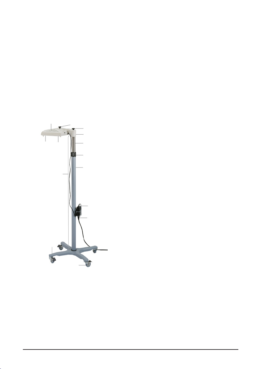
The Lullaby LED Phototherapy System consists of the Lamp enclosure, Pedestal Assembly and
Base assembly.
Part Illustration Function
1.1
3
Figure 2-1 : LED phototherapy System
2.1
2.2
2.3
11.2
2
2.4
2.5
2.6
2.7
2.8
3.1
1. Lamp Enclosure: The Lamp enclosure has
10 LED lamps enclosed in a plastic housing,
which forms the light source. It consists of
two parts- the upper enclosure and the lower
enclosure. The lamp enclosure can be tilted to
approximately 90° from the horizontal position.
1.1 Air-vent: The air vents provide ventilation to
the device when it is in use.
1.2 Handle: Depression provided on either side
to help hold the Lamp enclosure.
2. Pedestal Assembly: The pedestal consists of
the following parts:
• Knobs: The knobs secure the Lamp
enclosure to the Arm (2.3). By removing
the knobs the Lamp enclosure can be
detached and used independently.
2.1 Tilt knob: This knob can be loosened to tilt
the lamp enclosure.
2.2 Securing Knob: The retaining knob secures
the lamp enclosure to the Arm (2.3).
2.3 Arm: The Arm is xed to the pedestal and
supports the lamp enclosure.
2.4 Inner tube: This part supports the Arm (2.3).
The inner tube can be adjusted to vary the
height of the lamp enclosure.
2.5 Height Adjust Lock: This part secures the
inner tube at the desired height.
2.6 Outer tube: This part is xed to the Base.
2.7 SMPS Holder: This part is attached to the
outer tube to place the SMPS (DC power
supply).
2.8 SMPS with power cord: The power unit with
power cables to supply power to the unit.
© 2011 by General Electric Company. All rights reserved. 2051539-001 Rev F 11
Page 12
Product Description
Part Illustration
1.1
1.2
1
2
3
2.1
2.2
2.3
2.4
2.5
2.6
2.7
2.8
3.1
Function
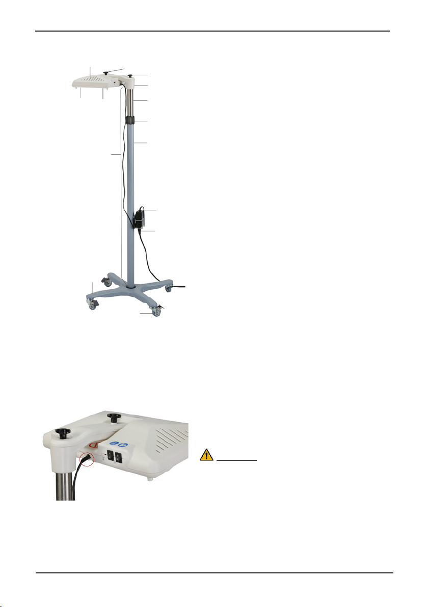
3. Base Assembly: The base is designed to
provide stability at any height or angle of the
lamp enclosure.
3.1 Casters with brake: The swivel casters
add mobility to the device. The brakes
on each caster, when actuated, prevents
movement.
Note: To move the equipment hold the unit below
the height adjust lock.
2.3 Controls, Indicators, Mechanical controls
This section describes, in detail, the components of the Lullaby LED Phototherapy System.
2.3.1 Controls
DC Jack (Refer Figure 2-2): The device is powered
by a 24V SMPS. The power supply cable from the
SMPS is connected to the DC jack on the lamp
enclosure.
WARNING
1. The use of power cords and SMPS other than
those specied by the manufacturer might
aect the performance of the unit and could
result in damage to the unit.
Figure 2-2 : DC Jack
12 2051539-001 Rev F © 2011 by General Electric Company. All rights reserved.
2. It may also create an unsafe operating
condition, exposing a user to electric shock.
Page 13
2
1
Figure 2-3 : Lamp enclosure
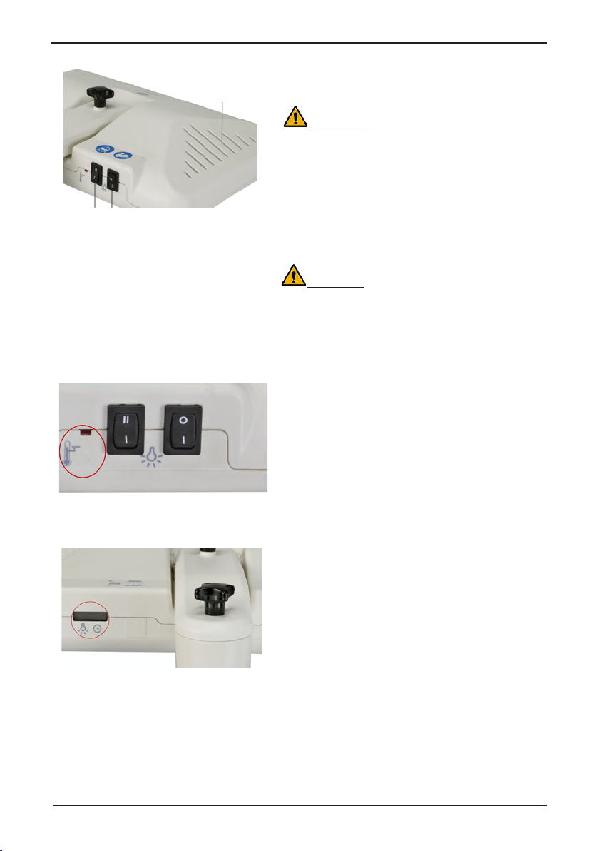
2.3.2 Indicators
Product Description
Power ON/OFF Switch (Refer 1 of Figure 2-3):
3
This switch turns ON and OFF the power supply to
the device.
WARNING
Disconnect the power cord to completely cut-o
the power supply to the device.
Irradiance Selection Switch (Refer 2 of Figure
2-3): The irradiance selection switch is used to
select light intensity-low or high irradiance.
Air Vent (Refer 3 of Figure 2-3): The air vents
helps to circulate the air inside the lamp enclosure
and maintain its temperature when in use.
WARNING
Ensure that the air vents are not covered or
obstructed when the unit is being used.
Over Temperature Cut-O Indicator (Refer
Figure 2-4): This indicator glows when the device
shuts down due to over temperature (exceeds
85°C) inside the lamp enclosure.
NOTE: In normal operating condition this indicator
is OFF.
Figure 2-4 : Over temperature cut-o
indicator
Lamp Life Timer (Refer Figure 2-5): The Lamp
life timer indicates the number of hours the LED
lamps have been used.
NOTE: GEHC recommends, replacing the lamp
after 50000 hours.
Figure 2-5 : Lamp life timer
© 2011 by General Electric Company. All rights reserved. 2051539-001 Rev F 13
Page 14

Product Description
2.3.3 Mechanical Controls
Figure 2-6 : Height adjust lock
To DC Jack
SMPS
SMPS Holder
Height Adjust Lock (Refer Figure 2.6): This part
secures the inner tube at the desired height. The
inner tube is released when the lock is turned
counterclockwise allowing the height of the lamp
enclosure to be adjusted.
WARNING
Always support the lamp enclosure with one hand
when releasing the lock to adjust the height.
SMPS Holder (Refer Figure 2-7): The holder is
xed to the outer tube to support the SMPS (power
supply unit).
SMPS (Refer to Figure 2-7): The power supply
unit is connected with power cables. The cable is
connected to the DC jack, on the Lamp enclosure,
at one end and to the AC power source on the
other.
To AC Power source
CAUTION
Wrap the excess cord around the SMPS holder to
avoid the cord from trailing when moving or using
Figure 2-7 : SMPS with power cables in
SMPS holder
the device.
Base (Refer Figure 2-8): The base keeps the
device unit in a stable position.
Casters with position lock (Refer Figure 2-9):
The swivel centre casters oer easy mobility in
all directions. The casters can be kept in place by
locking it in position using the brake lever.
Figure 2-8 : Base Assembly
WARNING
1. Always support the pedestal with one hand
while locking or unlocking the casters.
2. Ensure that the brakes on all four casters are
unlocked before moving the unit.
Figure 2-9 Caster with brake lever
14 2051539-001 Rev F © 2011 by General Electric Company. All rights reserved.
Page 15

Chapter 3: Operating Procedure
The following section describes the operating procedure of the device. For detailed
instructions on installing and setup refer to Chapter 3 : Installing and Setup, in Service
manual ( 2054622-001).
3.1 Operating Instructions
The following section provides step-by-step instructions to ensure that the Lullaby LED
Phototherapy System provides eective phototherapy treatment:
• Read this manual and all accompanying documents.
• Note the WARNING and CAUTION statements that appear in this manual and all
accompanying documents.
• Read the User Responsibility Statement available in the beginning of this manual.
• Read the Warranty: It describes GE Healthcares’ responsibility in case of a functional
defect.
• Keep this manual and all accompanying documents for future reference.
3.2 Checking equipment before use
Before using the equipment inspect for the following:
• Examine the power cord and the light unit for obvious signs of damage. If damaged, do
not put the unit in use and contact GE authorized, service personnel.
• Verify that air circulation vents on the light unit are not covered or obstructed.
• Check for the power supply, connect the power supply cord to the DC Jack on the light
unit and the other end to the main power supply. Wrap the power cord around the
SMPS holder to prevent tripping.
• Test the lamps, turn On the lamp On/O switch on the rear end of the Lamp enclosure.
Turn on the irradiance selection switch and observe the lamp illumination. Use the
Ohmeda Medical Biliblanket Meter II to check the irradiance level.
• Ensure the light unit is securely locked to the pipe and the pedestal assembly. The light
unit can be tilted to a maximum of 90° angle from the horizontal axis of the pedestal.
Test the tilting mechanism.
• Ensure that the brakes on the wheel are actuated.
If any of the above activity does not perform as described , do not use the unit. Contact
qualied service personnel.
3.3 Preparing an Infant for phototherapy
After completing the checkout procedures on the equipment it is important to follow the
below mentioned procedures to get the maximum benet of the treatment:
1. Remove the infant clothing. Leaving the diaper on is at the discretion of the attending
physician.
2. Maximize skin surface area to be exposed to phototherapy treatment.
3. Cover the eyes of the infant using an appropriate eye shield.
4. If the baby has a skin temperature probe in place, ensure this is appropriately applied
to the infants skin and cover with a reective probe cover.
© 2011 by General Electric Company. All rights reserved. 2051539-001 Rev F 15
Page 16

Operating Procedure
5. Position the phototherapy unit over the infant and turn it ON. It is recommended to
measure the irradiance level after positioning the device.
NOTE : Factors to consider when using any phototherapy device to ensure proper treatment
include:
• Maximum body surface area exposed to phototherapy light
• Distance between the infant from the light source
• Intensity of light
• Duration of exposure to phototherapy
• Total serum bilirubin
• Skin thickness and pigmentation
3.4 Basic Operating Procedure
Below mentioned are the basic operating procedure of the Lullaby LED Phototherapy
System.
3.4.1 Adjusting the height of the Lamp enclosure
WARNING
Adjust the height and distance of the Lamp enclosure before positioning the Lullaby LED
Phototherapy System in therapy area.
NOTE: Do not adjust the height of the equipment with the patient directly under the unit.
3.4.1.1 Height Adjust Lock
The height of the Inner tube can be altered
with the Height adjust lock.
1. Hold the Inner tube with one hand.
2. Unscrew the Height adjust lock by turning
it anti-clockwise. Adjust the inner-tube of
the pedestal to increase or decrease the
height.
3. Tighten the Height adjust lock by turning
it clockwise at the desired height.
WARNING
1. Ensure that the Height adjust lock is
Figure 3-1 : Height Adjust Lock
secured tightly.
2. Ensure that the distance of the Lamp
enclosure is not less than 35 cm from the
patient.
3.4.2 Moving the device
The swivel casters allows to move the unit with ease in any direction, position the device in
the intended location and actuate the brakes.
NOTE: Before moving the device ensure that the brakes on all four casters are unlocked.
16 2051539-001 Rev F © 2011 by General Electric Company. All rights reserved.
Page 17

3.4.2.1 Swivel casters with brake
Figure 3-2 : Base with casters
Figure 3-3 : Casters with brakes actuated
3.4.3 Powering-ON the system
Connecting the power cord
Operating Procedure
1. Support the light unit with one hand.
2. Apply slight foot pressure on the locking
lever to actuate or unlock the casters.
1. Place the SMPS in the SMPS holder (Figure
3-4).
2. Connect the DC plug of the SMPS cable into
the DC jack (Figure 3-5).
3. Fix the power cord to the SMPS (Figure 3-4)
and connect the other end of the power
cord to the mains supply.
q CAUTION
Ensure that the power cord is not in the way
of frequent movement to avoid accidental
tripping.
Figure 3-4 : SMPS Holder
© 2011 by General Electric Company. All rights reserved. 2051539-001 Rev F 17
Page 18

Operating Procedure
Figure 3-5 : DC Jack
Figure 3-6 : Power ON/OFF switch
4. Turn ON the mains and the Power ON/OFF
switch on the Lamp enclosure (Refer Figure
3-6). The blue LED lamps will glow (Figure
3-7).
Figure 3-7 : LED Phototherapy System with
lamps ON
3.4.4 Selecting Irradiance level
The intensity of the blue LED lamps can be controlled using the Irradiance selection switch.
3.4.4.1 Irradiance level
1. Select the irradiance level. The symbol II
on the switch indicates high intensity and
I for low intensity. The nominal output at
high intensity is: 45 µW/ cm2/nm ±25%
and 22 µW/ cm2/nm ±25% at low intensity
setting.
NOTE: Monitor the patient during treatment as
Figure 3-8 : Irradiance selection switch
18 2051539-001 Rev F © 2011 by General Electric Company. All rights reserved.
per hospital guidelines.
Page 19

3.5 Tilting the Lamp enclosure
The Lamp enclosure can be tilted at an angle up to 900.
3.5.4.1 Tilting the light unit:
1. To tilt the Lamp enclosure loosen
2. Tilt the unit to the desired angle as
3. Tighten the Tilt knob by turning it
Always support the light unit with one
hand when loosening or tightening the
tilting knob.
Figure 3-9 : Tilt knob
Operating Procedure
the Tilt knob, indicated in the gure,
by turning it counter clockwise.
shown in Figure 3-9.
clockwise.
WARNING
Figure 3-10 : Tilted at an angle
3.6 Using with other devices
The device can be used independently or with other devices such as radiant warmer or
incubator. When using it in such situations ensure that the heat source of the devices do
not conict or interfere with the functioning of other equipment.
q CAUTION
Follow hospital guidelines and medical protocol when using LED Phototherapy System with
other device.
© 2011 by General Electric Company. All rights reserved. 2051539-001 Rev F 19
Page 20

Operating Procedure
Figure 3-11 : Correct positioning of the LED
phototherapy System when used with an Infant
Warmer
NOTE: The Over heat indicator in the LED
Phototherapy System may be activated if
the device is not correctly aligned to the
heat path of the Warmer.
The Figure 3-12 shows the LED
Phototherapy System in the path of the
Warmer, which is incorrect.
Figure 3-12 : Incorrect positioning of the LED
phototherapy System when used with an Infant
Figure 3-13 : Using the LED Phototherapy with an
20 2051539-001 Rev F © 2011 by General Electric Company. All rights reserved.
Warmer
Incubator
Page 21

Operating Procedure
3.7 Using Lamp enclosure in detached condition
The Lamp enclosure can be detached from the pedestal and used as a standalone unit.
This provides the exibility to adapt the device to suit any environment.
1. Unplug the power cord from the DC
jack.
2. Unscrew both the knobs (Tilt and
Securing knob) on the Lamp enclosure
(Figure 3-14).
3. Remove the upper arm (Figure 3-15)
4. Hold Lamp enclosure, tilt and lift it o
from the Arm (Figure 3-16).
Figure 3-14 : Removing the knobs
Figure 3-15 : Removing the upper arm
Figure 3-16 : Detaching the Lamp enclosure
5. The Lamp enclosure can now be used
safely over an incubator as shown
in Figure 3-17. Attach the DC power
supply cord in the DC jack and insert
the plug to the main power supply,
all other functionality of the Lamp
enclosure remain the same.
Note: Ensure the SMPS ( power supply ) is
properly supported and is not hanging free
when used in detach mode.
WARNING
1. Do not to move the incubator when
using the light unit as mentioned above.
2. Ensure that the air vents are not
covered or obstructed when the unit is
being used.
3. When used on top of an incubator there
is a possibility of reduction in the peak
irradiance at the incubator bed level.
The irradiance will depend on the type
of material and design of the incubator
canopy.
4. The lens surface on the Lamp enclosure
assembly could be as hot as 70 °C
during operation. Do not touch the lens
when the lamps are in ON condition.
5. Do not detach the unit whilst it is in ON
condition.
6. Do not detach the unit whilst it is placed
over an infant bed device.
Figure 3-17 : Using on an Incubator
© 2011 by General Electric Company. All rights reserved. 2051539-001 Rev F 21
Page 22

Operating Procedure
This page is left blank intentionally.
22 2051539-001 Rev F © 2011 by General Electric Company. All rights reserved.
Page 23

Chapter 4: Troubleshooting
A- When the following parts are damaged:
Upper enclosure, Lower enclosure, Pedestal
Assembly, Base Assembly. Refer to Figure 2-1
to identify the parts.
Remove the unit from service and
contact GE-authorized and trained
service personnel.
A: Damaged Parts
B: Jammed Parts
N
Check for any visible damage to the lower
arm. If there is any damage, remove the
device from service and contact GE-
authorized and trained service personnel.
B1- Lamp enclosure is drooping
The Lower arm may not be properly
engaged to the Inner tube. Remove
the Upper arm cover and check the
screws. If they are found to be loose,
remove the device from service and
contact GE-authorized service
personnel.
Y
The following owcharts describe likely symptoms, their causes and actions to be taken.
A- Damaged parts
B- Jammed Parts
C- Functionality Issues
© 2011 by General Electric Company. All rights reserved. 2051539-001 Rev F 23
Page 24

Y
Y
B2- Pedestal is sliding down
Check if the Height lock is properly engaged
on the threads of the Outer tube. Try to
disengage and tighten again. If the problem
persists follow the instructions, explained in
the box below.
Check if the Height lock inner is installed
within the Outer lock. If there is no Height
lock inner, remove the device from service
and contact GE-authorized and trained
service personnel.
Y
Y
B3- No Mobility
Check if the brakes are actuated. If so,
release them on all four wheels and try
moving the device. If the problem persists,
check for the following issue.
Check the caster for visible damage, check
for jammed brake levers. The part may
need replacement. Remove the device
from service and contact GE-authorized,
trained service personnel.
Troubleshoot
24 2051539-001 Rev F © 2011 by General Electric Company. All rights reserved.
Page 25

The Horizontal hinge may be damaged or
the Upper enclosure around the horizontal
hinge may be cracked or damaged.
Remove the unit from service and contact
GE-authorized and trained service
personnel.
The thread on the knob may be damaged.
To replace the knob, order spare parts
from the Field Replaceable Unit (FRU) kit.
Contact GE-authorized and trained service
personnel for replacement parts.
B4.1- Lamp enclosure does not
maintain the selected angle.
Y
N
N
Y
B4- Lamp enclosure cannot be tilted.
The knob may be over tightened-try to
release and tighten. If the problem
persists, the knob may need replacement.
Contact GE-authorized and trained service
personnel for replacement parts.
The threads on the Lower arm in which the
knobs get engaged may be damaged.
Replace the Lower arm. Contact GE-
authorized and trained service personnel
for replacement parts.
N
Troubleshoot
© 2011 by General Electric Company. All rights reserved. 2051539-001 Rev F 25
Page 26

Y
If still problem persist remove the unit
from service and contact GEauthorized and trained service
personnel.
Plug the power cord into an outlet.
Turn the mains and the Power switch
ON.
Ensure that the air vents on the light
unit are not obstructed.
Y
C1- Lamp Hour Timer is not working
The power supply to the unit is not ON.
Switch the power ON. If the problem
persists, remove the unit from service
and contact GE-authorized, trained
service personnel.
C2- Lamp unit overheated indicator is
ON
Turn OFF the mains switch and
disconnect the power cords from the
outlet
C: Functionality Issues
Ensure the area around the
equipment is not congested and is
well ventilated by air conditioning or
natural means.
Allow the unit to cool down. The
Overheated Indicator will reset when
the unit cools. Start using the device
after it resets.
Troubleshoot
26 2051539-001 Rev F © 2011 by General Electric Company. All rights reserved.
Page 27

Y
A thermal shut down has occurred
due to overheating of the device.
Check for blockage of air vents and
follow the steps as in C2.
N
C3- No light output
Ensure that the unit is powered ON.
The DC power supply cord may not be
in proper contact in the DC Jack.
Reinstate the plug into the DC jack and
power ON.
Check the Power ON/OFF switch for
continuity. If the switch is loose or is
visibly damaged, remove the unit from
service and contact GE-authorized,
trained service personnel.
Y
Y
Troubleshoot
© 2011 by General Electric Company. All rights reserved. 2051539-001 Rev F 27
Page 28

Ensure that the lamp light is within
50000 from the last replacement.
Y
C4- Light output measurement
is out of specification
Ensure that the Lamp enclosure height
is set as per the specification of 35cm
between the patient and lamp
enclosure.
Ensure that the voltage is within the
specified voltage range of 100-240V.
Measure the light output with
Ohmeda Medical BiliBlanket Meter II.
If still problem persist remove the unit
from service and contact GEauthorized and trained service
personnel.
Troubleshoot
28 2051539-001 Rev F © 2011 by General Electric Company. All rights reserved.
Page 29

Chapter 5: Cleaning and Maintaining
5.1 Cleaning
1. Ensure the mains power cord is disconnected from the power source before cleaning.
2. Use approved cleaning solution. Clean the outside of the light unit using a mild
detergent solution. Aqueous solutions ( hospital disinfectants and micro bactericides)
may be used.
3. Apply the cleaning solutions with a clean cloth or sponge. Do not allow liquids to seep
into the housing (air vents). Always dry the parts with a clean, damp, soft cloth to avoid
scratches and remove any cleaner residue.
4. Do not spray cleaner directly on the unit.
5. Make sure that the unit is completely dry before using it.
The following table lists approved cleaning solution:
Generic Formulation Maximum Concentration Level
Hydrogen Peroxide 6%
Sodium Hypochlorite 0.5% Aqueous Solution
Cavicide® 100% spray (Applied to cleaning cloth, not directly on equipment)
Glutaraldehyde 2%
Iodophor Solution 0.27%
5.2 Maintaining
It is necessary to maintain the equipment for optimum performance every time you use it
WARNING
Do not use a phenol compound-based cleaner. Phenol compounds have been associated
with elevated bilirubin levels in infants.
qCAUTION
1. Never immerse the light unit in liquid. It may cause electrical short-circuit resulting in
permanent damage.
2. Use the cleaning solution sparingly on a cloth when cleaning the exterior of the light
unit. Do not saturate the cloth; excessive solution could ow into the light unit and
damage internal components.
3. Do not autoclave or gas sterilize the light unit.
4. Cleaning solutions such as iodine solutions will reduce the unit’s light output. Do not
use iodine solutions, strong acids, strong alkali, or bleach solutions to clean the unit.
© 2011 by General Electric Company. All rights reserved. 2051539-001 Rev F 29
Page 30

Cleaning and Maintaining
This page is left blank intentionally.
30 2051539-001 Rev F © 2011 by General Electric Company. All rights reserved.
Page 31

Appendix A: Specications
NOTE: The specications are subject to change without notice
Specications
20 W maximum at 100-240 V ~, 50/60 Hz
Over temperature
protection
Touch current
Environmental Operating Requirements
Ambient temperature +10°C to +40°C
Humidity 20% to 95% RH non-condensing
Atmospheric pressure 70 kPa to 106 kPa
Storage and Transportation Requirements
Temperature 0°C to +70°C
Humidity 10% to 95% RH non-condensing
Atmospheric pressure 50 kPa to 106 kPa
Performance Specications
Spectral Irradiance
*Using an Ohmeda Medical
BiliBlanket Meter II
Wavelength range 400 - 550 nm (Dominant wavelength range is 450 - 465 nm)
LED Lamps
Power cuto for temperature greater than or equal to 85°C
Less than 500 μA at 264 VAC RMS (power on) with ground
intact for normal and reverse polarity and with ground
open for normal and reverse polarity.
High Irradiance Mode: 45 µW/ cm2/nm ±25%, 15-point
check at a distance of 35 cm from the light unit
Low Irradiance Mode: 22 µW/ cm2/nm ±25%, 15-point
check at a distance of 35 cm from the light unit
Typical lamp life is approximately 50000 hours before an
irradiance drop of 30%
Physical Specication
Overall dimension (Lx Bx H) 530 mmx 550 mmx 1700 mm (at maximum height)
Regulatory Standards
IEC Class 1 (continuous
operation)
EMC Class -A, CISPR 11,
Group 1
© 2011 by General Electric Company. All rights reserved. 2051539-001 Rev F 31
TÜV Rheinland CB certied to the following standards: IEC
60601-2-50; IEC 60601-1; IEC 60601-1-2
Certied under IECEE CB scheme
Page 32

Appendix A
This page is left blank intentionally.
32 2051539-001 Rev F © 2011 by General Electric Company. All rights reserved.
Page 33

Appendix B: Technical Reference
B.1 Eective Surface Area
The eective surface area of irradiance at a distance of 35 cm from the bed surface is 50
cm x 30 cm, and the maximum irradiance is 45 μW/cm2/nm ±25% at the high irradiance
mode. Once the phototherapy light is on and positioned over the patient, measure the
spectral irradiance with Ohmeda Medical BiliBlanket Meter II.
Figure B-1 : Eective Surface Area
B.1.1 Spectral Irradiance vs Distance
Distance from hood
bottom to bed
surface (cm)
35 50 x 30 45 35
40 50 x 30 40 31
50 50 x 30 31 25
© 2011 by General Electric Company. All rights reserved. 2051539-001 Rev F 33
Surface Area (L x
W) (cm)
Irradiance Ebi max
(µW/ cm2/nm)
Mean Irradiance (Ebi
15) (µW/ cm2/nm )
Page 34

Appendix B
Figure B-2 : Spectral Irradiance Vs Distance
Figure B-3 : Spectral Response Curve
34 2051539-001 Rev F © 2011 by General Electric Company. All rights reserved.
Page 35

Appendix B
B.2 Service Maintenance
The unit should be serviced and maintained by qualied service personnel. Follow hospital
and local regulations for scheduled maintenance frequency.
B.3 Part Replacement
There are specic parts that can be replaced when it is damaged or is not performing as
described. Contact a GE authorized personnel to know more about replaceable parts and
when a replacement is required.
Note: Always use only GE Healthcare replacement parts. Failure to use authentic parts may
result in malfunctioning of the equipment.
© 2011 by General Electric Company. All rights reserved. 2051539-001 Rev F 35
Page 36

Appendix B
This page is left blank intentionally.
36 2051539-001 Rev F © 2011 by General Electric Company. All rights reserved.
Page 37

Appendix C: Electromagnetic Compatibility (EMC)
Changes or modications to this system not expressly approved by GEHealthcare could
cause EMC failures with this or other equipment. This system is designed and tested to
comply with applicable regulation regarding EMC and needs to be installed and put into
service according to the EMC information stated as follows:
q CAUTION
1. Use of portable phones or other radio frequency (RF)-emitting equipment near the
system could cause unexpected or adverse operation.
2. The equipment or system should not be used adjacent to, or stacked with, other
equipment. If adjacent or stacked use is necessary, the equipment or system should
be tested to verify normal operation in the conguration in which it is being used.
C.1 Electromagnetic Emission
The Lullaby LED Phototherapy System is intended for use in the electromagnetic
environment specied below. It is the responsibility of the customer or user to ensure that
the Lullaby LED Phototherapy System is used in such an environment.
Emission Test Compliance Electromagnetic Environment -Guidance
The equipment uses RF energy only for
its internal function. Therefore, its RF
RF emissions EN 55011 Group 1
RF emissions EN 55011 Class A
Harmonic Emissions EN
61000-3-2
Voltage uctuations/ Flicker
emissions EN 61000-3-3
Class A
Complies
emissions are very low and are not likely
to cause any interference in nearby
electronic equipment.
The equipment is suitable for hospital
or clinic use only. The equipment should
not be used on public, low-voltage power
networks that supply domestic buildings
Immunity Test EN 60601 Test
Level
Electrostatic
discharge (ESD)EN
61000-4-2
© 2011 by General Electric Company. All rights reserved. 2051539-001 Rev F 37
± 6kV contact
± 8kV air
Compliance Level Electromagnetic
Environment -
Guidance
± 6 kV contact
±8 kV air
Floors should be wood,
concrete or air ceramic
tile. If oors are covered
with synthetic material,
the relative humidity
should be at least 20 %.
Page 38

Appendix C
Immunity Test EN 60601 Test
Level
Electrical fast
transient/burst EN
61000-4-4
Surge EN 61000-4-5 ± 1kV dierential
Voltage dips, short
interruptions and
voltage variations on
power supply input
lines EN 61000-4-11
NOTE: UT is the a.c mains voltage prior to application of test level.
Power frequency
(50/60 Hz) magnetic
eld EN 61000-4-8
Conducted RF EN
61000-4-6
Radiated RF EN
61000-4-3 EN
60601-2-50
±2kV for power
supply lines
± 1kV for input/
output lines
mode
± 2kV common
mode
<5% UT (>95%
dip in UT ) for 0.5
cycles
40% UT (60% dip
in U
) for 5 cycles
T
70% U
dip in UT ) for 25
cycles
<5% UT (>95%
dip in U
seconds
3A / m 3A / m Power frequency
3 V rms, 150kHz to
80MHz
3V / m, 80MHz to
2.5GHz 10V / m,
(30%
T
) for 5
T
Compliance Level Electromagnetic
±2kV for power
supply lines
± 1kV for input/
output lines
± 1kV dierential
mode
± 2kV common
mode
<5% U
(>95%
T
dip in U
cycles
40% U
in UT ) for 5 cycles
70% UT (30%
dip in UT ) for 25
cycles
<5% U
dip in UT) for 5
seconds
3 V rms Interference could
3V / m, 10 V / m
) for 0.5
T
(60% dip
T
(>95%
T
Environment -
Guidance
Mains power quality
should be that of
a typical hospital
environment.
Mains power quality
should be that of
a typical hospital
environment.
Mains power should
be that of a typical
hospital environment.
If the equipment
requires continued
operation during power
mains interruptions,
it is recommended
that the Lullaby LED
Phototherapy be
powered from an
uninterrupted power
supply.
magnetic elds should
be at levels of a typical
hospital environment.
occur in the vicinity of
equipment marked with
the following symbol:
38 2051539-001 Rev F © 2011 by General Electric Company. All rights reserved.
Page 39

Appendix C
P
V
d
=
1
5.3
P
E
d
=
1
5.3
P
E
d
=
1
7
Recommended separation distances between portable and mobile RF
communications equipment and the Lullaby LED PT
The Lullaby LED PT is intended for use in an electromagnetic environment in which
radiated RF disturbances are controlled. The customer or the user of the Lullaby LED
PT can help prevent electromagnetic interference by maintaining a minimum distance
between portable and mobile RF communications equipment (transmitters) and the
Lullaby LED PT as recommended below, according to the maximum output power of the
communications equipment.
Separation distance according to frequency of transmitter
(Meters)
Rated maximum
output power of
transmitter
(W)
0.01 0.12 0.12 0.04 0.23 0.07
0.1 0.38 0.38 0.11 0.73 0.22
1 1.2 1.2 0.35 2.3 0.7
10 3.8 3.8 1.11 7.3 2.2
100
For transmitters rated at a maximum output power not listed above, the recommended
separation distance d in Meters (m) can be estimated using the equation applicable to
the frequency of the transmitter, where P is the maximum output power rating of the
transmitter in watts (W) according to the transmitter manufacturer.
NOTE 1: At 80 MHz and 800 MHz, the separation distance for the higher frequency range
applies.
NOTE 2: These guidelines may not apply in all situations. Electromagnetic propagation is
150 kHz to 80 MHz
3Vrms 3V/m 10V/m 3V/m 10V/m
12 12
80 MHz to 800 MHz
800 MHz to 2.5 GHz
1.11 23 7
aected by absorption and reection from structures, objects and people.
C.2 CE Marking Information
Compliance
The Lullaby LED Phototherapy System bears the CE mark, indicating its conformity with
the provisions of the Council Directive 93/42/EEC, concerning medical devices and fullls
the essential requirements of Annex I of this directive. Any other directive(s) and all the
standards the product complies to are listed in the general information of the operator’s
manual. The country of manufacture can be found on the equipment labeling. The
safety and eectiveness of this device has been veried against previously distributed
devices. Although all the standards applicable to presently marketed devices may not be
appropriate for prior devices (i.e. electromagnetic compatibility standards), this device will
not impair the safe and eective use of those previously distributed devices.
© 2011 by General Electric Company. All rights reserved. 2051539-001 Rev F 39
Page 40

Appendix C
C.3 Recommendation
Users should be aware of known RF sources, such as radio or TV stations and hand-held or
mobile two-way radios, and consider them when installing a medical device or system. Be
aware that adding accessories or components, or modifying the medical device or system
may degrade the EMI performance. Consult with qualied personnel regarding changes to
the system conguration.
Operating the system near radio frequency (RF) electromagnetic interference (EMI) above
the conditions dened in the EMC Standard EN60601-1-2 for Radiated Immunity (eld
strengths above 3 V/m) may cause malfunctions.
Medical Electrical Equipment needs special precautions regarding EMC and needs to
be installed and put into service according to the EMC information provided in this
manual. Review the AAMI Committee Technical Information Report (TIR) 18, “Guidance on
Electromagnetic Compatibility of Medical Devices for Clinical/Biomedical Engineers”. This
guidance document provides a means to evaluate and manage the EMI environment in the
hospital. The following actions can be taken to reduce the risk of medical device EMI and
achieve EMC:
• Assess the EMC environment of the healthcare facility (e.g., identify radio
transmitters in around the facility) and identify areas where critical medical
devices are used (e.g., ER, ICU, CCU, NICU).
• Increase the distance between sources of EMI and susceptible devices.
• Remove the devices that are highly susceptible to EMI.
• Lower the power transmitted from electrical and electronic equipment (EMI
sources) under hospital control (i.e. paging systems).Label devices susceptible to
EMI.
• Educate healthcare facility sta (nurses and doctors) to be aware of, and to
recognize, potential EMI related problems.
Notes
LED Phototherapy System
Description Number
Serial number of the unit
NOTE: For the serial number of the device, refer to the rating label on the Lamp assembly.
Record the serial number of the device in the space provided above for reference.
40 2051539-001 Rev F © 2011 by General Electric Company. All rights reserved.
Page 41

Warranty
This Product is sold by GE Healthcare under the warranties set forth in the following
paragraphs. Such warranties are extended only with respect to the purchase of this Product
directly from GE Healthcare or GE Healthcare’s Authorized Dealers as new merchandise
and are extended to the Buyer thereof, other than for the purpose of resale. For a period
of twelve (12) months for the light unit from the date of original delivery to Buyer or to
Buyer’s order, but in no event for a period of more than two years from the date of original
delivery by GE Healthcare to a GE Healthcare Authorized Dealer, this Product, other than
its expendable parts, is warranted to be free from functional defects in materials and
workmanship and to conform to the description of the Product contained in this operation
manual and accompanying labels and/or inserts, provided that the same is properly
operated under the conditions of normal use, that regular periodic maintenance and
service is performed and that replacements and repairs are made in accordance with the
instructions provided.
The foregoing warranties shall not apply if the Product has been repaired other than by
GE Healthcare or in accordance with written instructions provided by GE Healthcare, or
altered by anyone other than GE Healthcare, or if the Product has been subject to abuse,
misuse, negligence, or accident. GE Healthcare’s sole and exclusive obligation and Buyer’s
sole and exclusive remedy under the above warranties is limited to repairing or replacing,
free of charge, at GE Healthcare’s option, a Product, which is telephonically reported to the
nearest GE Healthcare Regional Service Oce and which, if so advised by GE Healthcare,
is thereafter returned with a statement of the observed deciency, not later than seven (7)
days after the expiration date of the applicable warranty, to the designated GE Healthcare
Service Center during normal business hours, transportation charges prepaid, and which,
upon GE Healthcare’s examination, is found not to conform with above warranties. GE
Healthcare shall not be otherwise liable for any damages including but not limited to
incidental damages, consequential damages, or special damages. There are no express
or implied warranties, which extend beyond the warranties hereinabove, set forth. GE
Healthcare makes no warranty of merchantability or tness for a particular purpose with
respect to the product or parts thereof.
© 2011 by General Electric Company. All rights reserved. 2051539-001 Rev F 41
Page 42

North America
Datex-Ohmeda, Inc.
PO Box 755 0
Madison, Wisconsin 53707-7550
USA
Tel +1 800 345 2700
Europe, Middle East, Africa
GE Healthcare
P.O. Box 900
FIN-00031 GE
Finland
Tel +358 10 39411
Fax +358 9 146 3310
Latin America
GE Healthcare
Av. Das Nacoes Unidas, 8501 - 3rd Floor
Sao Paulo - SP
Brazil - 05425-070
Tel: (55-11) 3067-8000
Ohmeda Medical,
A Division of Datex-Ohmeda, Inc.,
A General Electric Company
8880 Gorman Road
Laurel MD 20723
USA
Asia Pacic
China
GE Healthcare
Maxdo Center No. 8 Xing Yi Road,
Hong Qiao Development Zone
Shanghai , China
Tel + 65 62773444
Japan
67-4 Takakura-cho, Hachioji-shi,
Tokyo, 192-0033, Japan
Australia & New Zealand
Unit 3, 310 Ferntree Gully Road,
Nottinghill, Victoria, 3168, Australia
South East Asia
Singapore
Tiong Bahru Road Central Plaza
#12-01/06, 168730, Singapore
Korea
7th Floor, GE Tower 71-3, Cheongdamdong, Gangnam-gu,
Seoul, 135-100, Korea
EC Representative
GE Medical Systems SCS
283 Rue de la Minière
78530 BUC
FRANCE
Made in India
Black on white
A5 paper size
Two (2) sides print
Coil Binding
Printed in India
 Loading...