

Page 1
GE
Installation Guide
Lighting
LED Cove Lighting System
LED ARCHITECTURAL SERIES
Product Codes
73098, 73099, 73100, 73101, 73826, 74892, 62193, 62194, 62197, 62198
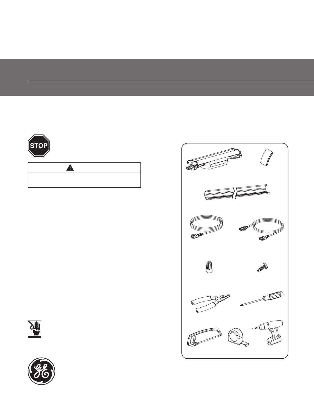
Tools and Components
BEFORE YOU BEGIN
Read these instructions completely and carefully.
WARNING
Risk of re, electrical shock or injury. Observe the
following instructions when installing this product.
LED Cove Fixture
Light Shield Connector (Optional)
(62818)
• This product is intended solely for the use of non-residential architecture
lighting and is not intended for use in any other application.
• Before installing, servicing or cleaning unit, switch power off at the service
panel and follow appropriate lock out/tag out safety procedures.
PLAN YOUR INSTALLATION
Inspect the planned area for your installation and prepare a sketch and materials
list for LED Cove xtures, mounting tracks, leader cables and jumper cables.
FOR 120VAC INSTALLATIONS:
• No more than 200 LED Cove xtures (~200 feet/60.96m) are recommended
to be run in series.
FOR 240VAC INSTALLATIONS:
• No more than 330 LED Cove xture (~300 feet/91.44m) are recommended to
be run in series.
• Installing multiple 240V Cove xtures, on the same lighting circuit, may
cause GFI or RCD circuits to trip due to the ground leakage current of the
xtures. To avoid this issue, when designing lighting circuit s using GFI or
RCD protection, the total leakage current for a string of Cove xtures
should be calculated using the value of 0.5 mA per xture.
Prepare Electrical Wiring
Electrical Requirements
• Do not use in wet locations.
• The grounding and bonding of the LED Driver shall be done in
accordance with National Electric Code (NEC) Article 600.
• Follow all National Electric Codes (NEC) and local codes.
Mounting Track
0° (73105), 15° (73106), 30° (73107), 0° with light shield (62188)
Leader Cable
120V (73108, 75476)
240V (73617, 73618)
16 AWG (1.31mm2)
Wire Connector
Wire Stripper/Cutter
Hand Saw
Tape Measure
Jumper Cable (Optional)
120V (73109)
240V (73616)
#10 (M5)
Screws
Screw Driver
Power Drill
imagination at work
Page 2
Installation Guide
1
Materials
Tools
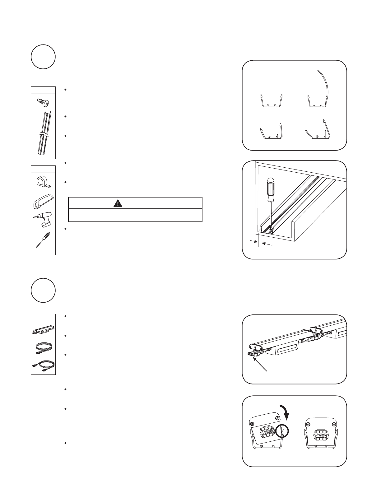
Install Mounting Tracks
NOTE: Select and use same degree angle mounting track
throughout entire installation.
Position mounting tracks in cove. Maintaining a xed distance
between the mounting track and the wall being illuminated is
critical for consistent appearance.
Maintain at least 0.5 inches (13 mm) between wall and
mounting track.
For curved sections or angles, cut and lay out sections of
mounting track spaced no less than 12 inches (305 mm) on
center along prole of wall to achieve desired radius.
A jumper cable can be placed between modules to provide a
gap in a single run.
Use a saw capable of cutting through 1/8-inch (3 mm) PVC to
cut mounting tracks to length as needed.
CAUTION
Risk of injury. Ensure that hands are free from cutting area.
Install a minimum of two #10 (M5) screws per cut section of
mounting track to x the track in place within the cove.
Select a mounting track
0º 0º with shield
15º 30º
0.5 inches (13 mm) minimum
2
Materials
Install LED Cove Fixtures
Unpack and lay out LED Cove xtures along the layout of
the mounting track.
Connect the leader cable to the male plug on the rst
LED Cove xture.
Connect LED Cove xtures together in series with the male
plug of the xture at the start of the run. You may connect
all LED Cove xtures together before snapping into
mounting tracks. This makes access to connections easier.
Connect female plug to male plug of next xture in
series.
Locate series of LED Cove xtures along mounting track until
you are satised with location and positioning of the xtures.
Use jumper cable as needed to work around any obstacles,
corners or separations.
Press down back end rst, then front end to snap the LED
Cove xtures into the mounting track. Ensure both locks are
engaged.
Leader cable connects to
male plug on rst xture
Snapping into track
Page 3

Work your way down the series of LED Cove xtures,
snapping them into place from the start to the end. Add dust
cap from Leader Cable to the last female plug in the series.
To adjust LED Cove xtures along track, uninstall them from
the track by pushing the front of the track open to release the
xtures, then adjust and snap back into place.
NOTE: Do not pull on the xtures once installed into the
mounting track. This will place tension on connecting cables
the xtures may not tolerate.
To separate xtures, squeeze the tabs on the male/female
plug connectors.
Installation Guide
Squeeze tabs
3
Materials
Tools
Prepare Electrical Wiring
Electrical Requirements
This device must be connected to an individual properly grounded branch circuit, protected by a
15 ampere circuit breaker.
Electrical connection of leader cable(s) to 120VAC or 240VAC must be prepared by a trained,
qualied personnel following all applicable state and national regulations.
CAUTION
Risk of damage to unit. Do not use 120VAC xture in a
240VAC circuit or a 240VAC xture in a 120VAC circuit.
Circuits used for LED Cove xtures may be switched or dimmed using standard electronic low-voltage (ELV)
reverse phase control dimmers.
The cut end of the leader cable will connect to the power
source, while the female plug connects to the male connector
on the rst LED Cove xture in the series.
Cut leader cable to required length to go from power source
to rst xture in series.
Carefully strip back the outer insulation from the cut end of the
leader cable exposing the three 16 AWG (1.31mm2) wires inside.
Risk of electrical shock. Disconnect power before install.
CAUTION
LED Cove xtures
120V Source
Electrical enclosure
Black (+)
White (-)
Green (ground)
Leader cable
Strip back the insulation on each of the wires 1/4-inch (6 mm)
in order to attach to power source.
Attach wires from leader cable to the following:
120V 240V
- Line Voltage: Black Brown
- Neutral: White Blue
- Ground: Green Green/Yellow
Energize the circuit and check the installation.
LED Cove xtures
240V Source
Electrical enclosure
Brown (+)
Blue (-)
Green/Yellow (ground)
Leader cable
Page 4

Installation Guide
4
5
Troubleshooting
Symptom Solution
All LED Cove xtures are OFF • Check AC input connection and/or check circuit breaker.
• Check male/female plug connectors on the LED Cove xtures for improper
connection(s) or short circuits.
• Ensure leader cable is securely connected to the male plug connector on the rst
LED Cove xture.
Some of the LED Cove
xtures are not illuminated
Shadows within cove • Re-position LED Cove xtures along mounting track and ensure xtures are securely
• Check male/female plug connectors on the LED Cove xtures for improper
connection(s) or short circuits.
• Ensure any jumper cables are securely connected between the male/female plug
connectors of the LED Cove xture.
locked into position.
• Adjust layout of mounting track to ensure uniformity of illumination within the cove.
• Adjust leader cable and/or jumper cable orientation to ensure cables do not cover
any LEDs.
Specications
SKU Voltage Maximum Run Length IP Rating
73098 (LC12/727/120V)
73099 (LC12/730/120V)
74892 (LC12/741/120V)
62193 (LC12/827/120V)
62194 (LC12/840/120V)
73100 (LC12/727/240V)
73101 (LC12/730/240V)
73826 (LC12/741/240V)
62197 (LC12/827/240V)
62198 (LC12/840/240V)
This device complies with Part 15 of the FCC Rules. Operation is subject to the following two conditions: (1) This device may not cause harmful
interference, and (2) this device must accept any interference received, including interference that may cause undesired operation. This Class
[A] RFLD complies with the Canadian standard ICES-003. Ce DEFR de la classe [ A ] est conforme á la NMB-003 du Canada.
Note: This equipment has been tested and found to comply with the limits for a Class A digital device, pursuant to part 15 of the FCC Rules.
These limits are designed to provide reasonable protection against harmful interference when the equipment is operated in a commercial
environment. This equipment generates, uses, and can radiate radio frequency energy and, if not installed and used in accordance with the
instruction manual, may cause harmful interference to radio communications. Operation of this equipment in a residential area is likely to
cause harmful interference in which case the user will be required to correct the interference at his own expense.
120VAC
120VAC
240VAC
240VAC
200 Fixtures
(~200 ft./60.96m)
200 Fixtures
(~200 ft./60.96m)
300 Fixtures
(~300 ft./91.44m)
300 Fixtures
(~300 ft./91.44m)
IP20
Dry Location Only
IP51
Dry or Damp
Location Only
IP20
Dry Location Only
IP51
Dry or Damp
Location Only
GE Lighting • 1-888-MY-GE-LED
GE Lighting Solutions, LLC is a subsidiary of the General Electric Company. Tetra is a trademark of GE Lighting. The GE brand and logo are trademarks of the General Electric Company.
© 2013 GE Lighting Solutions, LLC. Information provided is subject to change without notice. All values are design or typical values when measured under laboratory conditions.
(1-888-69-43-533)
• www.gelighting.com
ARCH049-100213
GEH-5997, 35-201578-189
 Loading...