

Page 1
KTC-CBS24/CBH24
Bullet Camera
Page 2

© 2003 GE Interlogix, Video Systems Group
All Rights Reserved.
Any GE Interlogix, Video Systems Group
software supplied with GE Interlogix, Video
Systems Group products is proprietary and
furnished under license and can be used or
copied only in accordance with the terms of
such license.
This document contains proprietary
information that is protected by copyright.
No part of this document may be
reproduced or transmitted in any form or by
any means without the prior written
permission of GE Interlogix, Video Systems
Group.
The information contained in this document
is subject to change without notice.
GE Interlogix, Video Systems Group, in
keeping pace with technological advances,
is a company of product innovation.
Therefore, it is difficult to ensure that all
information provided is entirely accurate
and up-to-date. GE Interlogix, Video
Systems Group accepts no responsibility for
inaccuracies or omissions and specifically
disclaims any liabilities, losses, or risks,
personal or otherwise, incurred as a
consequence, directly or indirectly, of the
use or application of any of the contents of
this document.
For the latest product specifications, visit
GE Interlogix, Video Systems Group online
at www.GE-Interlogix.com or contact your
GE Interlogix sales representative.
For technical support before and after installation, call 800-469-1676.
Technical support is available 24 hours a day, 7 days a week.
Call: Tech Support 800-469-1676 (6 A.M. – 5 P.M. PST Monday through Friday)
Tech Support 541-740-3589 (all other times)
Main 800-343-3358 or 541-754-9133
Fax: Tech Support 541-752-9096 (available 24 hours a day)
Main 541-754-7162
Web: www.GE-Interlogix.com
1043349A / September 2003
This equipment has been tested and
found to comply with the limits for a
Class A digital device, pursuant to part
15 of the FCC Rules. These limits are
designed to provide reasonable
protection against harmful interference
when the equipment is operated in a
commercial environment. This
equipment generates, uses, and can
radiate radio frequency energy and, if
not installed and used in accordance
with the instruction manual, may cause
harmful interference to radio
communications.
You are cautioned that any changes or
modifications not expressly approved
by the party responsible for compliance
could void the user's authority to
operate the equipment.
Page 3

Bullet Camera User Manual Before You Begin
BEFORE YOU BEGIN
Read these instructions before installing or operating this product.
Note: This installation should be made by a qualified service person and should conform to
local codes.
This manual provides installation and operation information. To use this
document, you must have the following minimum qualifications:
• A basic knowledge of CCTV systems and components
• A basic knowledge of electrical wiring and low-voltage electrical
hookups
Use this product only for the purpose for which it was designed.
Customer Support
For assistance in installing, operating, maintaining, and troubleshooting
this product, refer to this document and any other documentation
provided. If you still have questions, contact GE Interlogix, Video
Systems Group Technical Support:
GE Interlogix, Video Systems Group
Call: 800-469-1676
Fax: 541-752-9096
Note: You should be at the equipment, ready with details before calling Technical Support.
Conventions Used in this Manual
Boldface or button icons highlight command entries. The following
WARNING, CAUTION, and Note statements identify potential hazards:
* WARNING:
Improper use of this equipment can cause severe bodily injury or
equipment damage.
** CAUTION:
Improper use of this equipment can cause equipment damage.
Note: Notes contain important information about a product or procedure.
* This symbol indicates electrical warnings and cautions.
** This symbol indicates general warnings and cautions.
1043349A / Se
ptember 2003 3
Page 4
Introduction Bullet Camera User Manual
INTRODUCTION
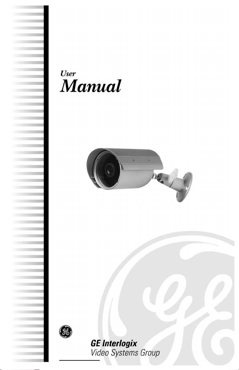
The standard- or high-resolution Bullet Camera includes a lens, a
housing, a bracket, mounting fasteners, power and video cables, and a
24 VAC power supply. To install the unit, see Figure 1 and Figure 2 and
perform the following.
Upper
LED illuminators
screw hole
Connector
Camera lens Light sensor Bracket (attached to lower
screw hole)
Figure 1. Camera components
Sunshield Sunshield screws (4)
Figure 2. Sunshield components
4 ptember 2003 1043349A / Se
Page 5
Bullet Camera User Manual Installing the Bracket and Camera
INSTALLING THE BRACKET AND CAMERA
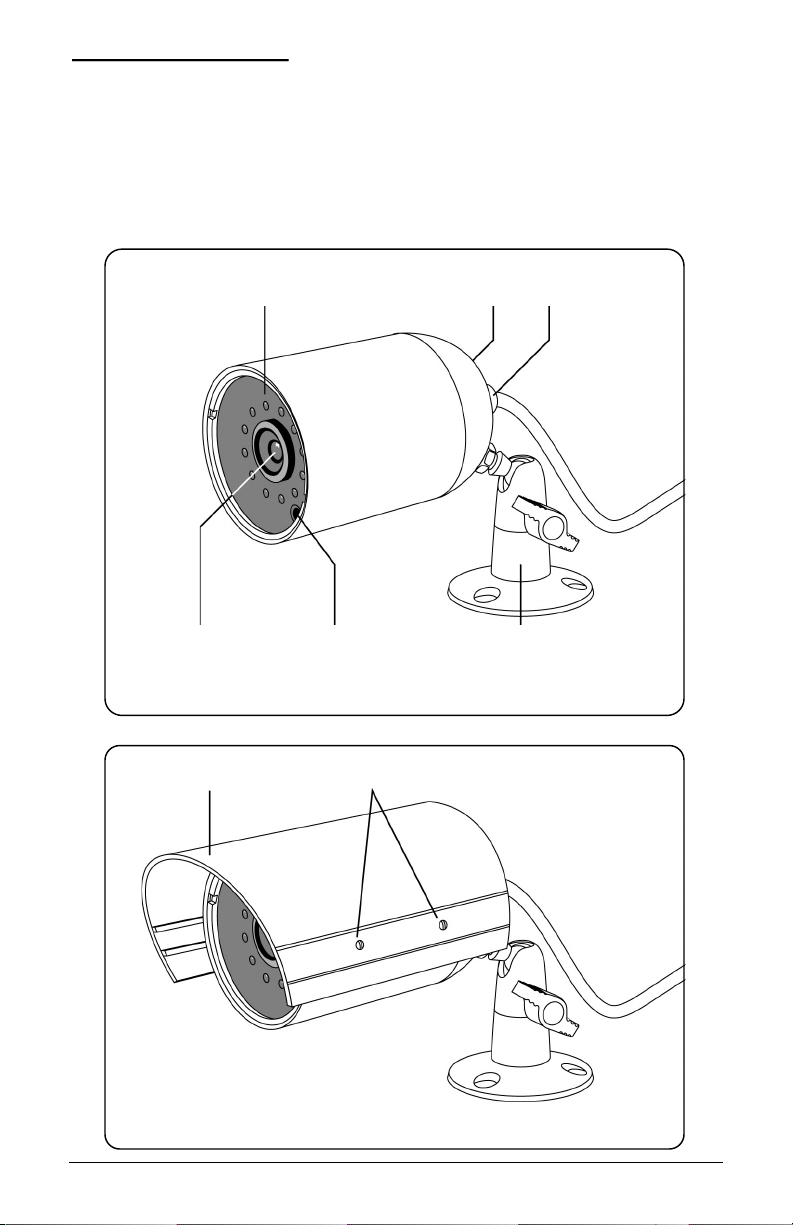
You can mount the camera on a vertical surface (Figure 3), and below
(Figure 4) or above (Figure 5) a horizontal surface.
Figure 3. Mounting on a vertical surface
Figure 4. Mounting below a horizontal
surface
Figure 5. Mounting above a horizontal
surface
1043349A / September 2003 5
Page 6

Installing the Bracket and Camera Bullet Camera User Manual
CHOOSING AN INSTALLATION LOCATION
Consider the field of view for the camera and the range of the LED
illuminators when you select an installation location.
• The LED illuminators are effective in nighttime conditions to
approximately 33 feet (10.1 m).
• See Table 1 for field of view information.
Table 1. Example approximate fields of view
Distance from camera Horizontal Vertical
5 ft (1.5 m)
10 ft (3 m)
15 ft (4.6 m)
20 ft (6.1 m)
Note: The Bullet Camera has a 1/3-inch CCD and 6.0 mm lens.
MOUNTING THE BRACKET
4 ft (1.2 m) x 3 ft (0.9 m)
8 ft (2.4 m) x 6 ft (1.8 m)
12 ft (3.7 m) x 9 ft (2.7 m)
16 ft (4.9 m) x 12 ft (3.7 m)
1) Loosen the wing nut and remove
the top of the bracket as shown in
Figure 6.
2) Place the back of the bracket
against the vertical or horizontal
mounting surface and mark the
location of the three mounting
holes.
Note: The camera comes with fasteners
and anchors; use them only if they are
appropriate for the type of mounting surface.
3) Prepare the mounting holes
appropriately according to the type
of surface (concrete, wood, etc.)
and fasteners used.
Figure 6. Removing the top of the
bracket from the mounting plate
6 ptember 2003 1043349A / Se
Page 7

Bullet Camera User Manual Installing the Bracket and Camera
4) Attach the mounting plate to the mounting surface as shown in
Figure 7.
5) Reinstall the top of the bracket onto the mounting plate and tighten
the wing nut as shown in Figure 8.
Figure 7. Attaching the mounting
plate to the mounting surface
Figure 8. Mounted bracket
1043349A / September 2003 7
Page 8
Installing the Bracket and Camera Bullet Camera User Manual
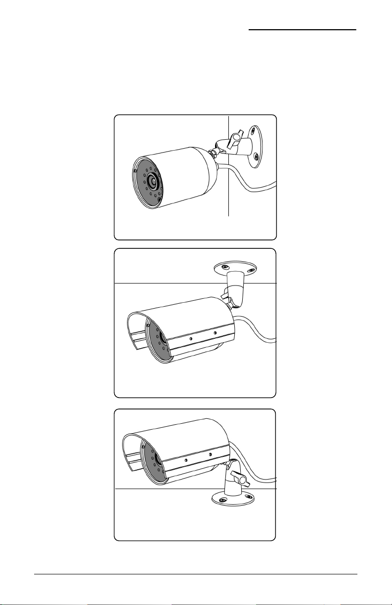
ATTACHING THE CAMERA TO THE BRACKET
See Figure 9 and perform the following.
Figure 9. Attaching the camera to the bracket
1) Loosen the wing nut to free the ball and socket bolt.
2) Slide the camera’s upper or lower screw hole onto the bolt.
3) Twist the ball and socket bolt into the camera screw hole.
4) Use the nut to secure the camera onto the bolt.
5) Tighten the wing nut.
8 ptember 2003 1043349A / Se
Page 9

Bullet Camera User Manual Installing the Bracket and Camera
ADJUSTING THE CAMERA ANGLE
See Figure 10 and perform the following.
Figure 10. Adjusting the camera angle
1) Loosen the wing nut.
2) Swivel the camera on the ball and socket bolt to achieve the proper
angle.
3) Tighten the wing nut to secure the camera in position.
1043349A / September 2003 9
Page 10
Installing the Bracket and Camera Bullet Camera User Manual
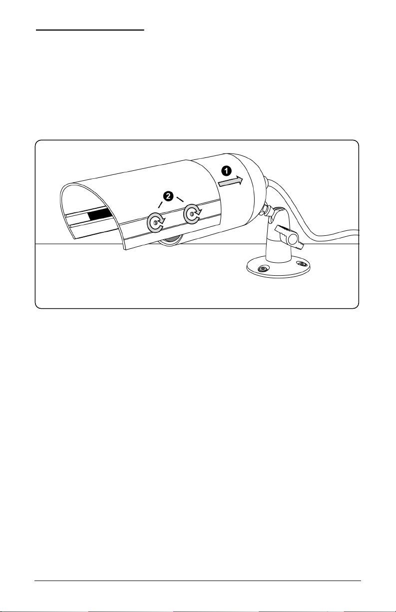
INSTALLING THE SUNSHIELD
Install the sunshield to protect the camera from rain and to minimize heat
build-up from sun exposure. To install the sunshield, see Figure 11 and
perform the following.
Note: For interior installations, the sunshield might not be necessary.
Figure 11. Installing the sunshield
1) Slide the sunshield into the desired position on the camera.
2) Tighten the sunshield screws (4) on both sides of the sunshield.
10 ptember 2003 1043349A / Se
Page 11

Bullet Camera User Manual Making Cable Connections
MAKING CABLE CONNECTIONS
See Figure 12 and perform the following.
Cable
To camera
receptacle Cable plug
Camera setting controls cover Video out Power in
Figure 12. Cable connections
1) Connect the camera’s cable receptacle to the cable plug.
2) Connect the video out connector to the video input on the monitor.
3) Connect the power in connector to the 24 VAC power supply.
4) Supply power to the unit.
1043349A / September 2003 11
Page 12

Installing the Bracket and Camera Bullet Camera User Manual
ADJUSTING CAMERA SETTINGS
To adjust backlight compensation
and vertical phase, on the 24 VAC
power supply open the camera
setting controls cover (see
Figure 12).
BACKLIGHT COMPENSATION
Backlight compensation controls iris
gain and white balance
simultaneously. If you have objects
in the foreground that appear
silhouetted in front of a brighter
background, set backlight
compensation to on. The
foreground objects appear with
greater definition.
Note: Compensation might be insufficient when the background is extremely bright.
To set backlight compensation see Figure 13 perform the following.
Phase control
buttons
Backlight compensation jumper
Figure 13. Camera setting controls
– +
• To set backlight compensation on, ensure that the jumper is
securely in place.
• To set backlight compensation off, remove the jumper.
VERTICAL PHASE
CAUTION:
The phase adjustment must be made by a qualified service person
or installer.
The vertical phase of the camera video signal can be synchronized to the
phase of the AC power line by using a dual-trace oscilloscope to observe
the video output signal (V-rate) of the camera and by adjusting the phase
control buttons (see Figure 13) to line up the phases of both signals or by
using a KTS-56 V-Phase Adjustment Tool.
12 ptember 2003 1043349A / Se
Page 13

Page 14

Page 15

Page 16

Mfg. # 98230006
 Loading...