

Page 1
Installation
Range Hood Connection to
Wall Switch
Instructions
If you have questions, call GE Appliances at 800.GE.CARES (800.432.2737).
JVX3240, JVX3300, JVX5305 and JVX5365
BEFORE YOU BEGIN
Read these instructions carefully and completely.
• IMPORTANT — Save these instructions
for local inspector’s use.
• IMPORTANT — Observe all governing
codes and ordinances.
• Note to Installer – Be sure to leave these
instructions with the consumer.
• Note to Consumer – Keep these instructions for
future reference.
• Proper installation is the responsibility of the installer
• Product failure due to improper installation is not
covered under the Warranty.
WARNING
TO REDUCE THE RISK
OF FIRE, ELECTRIC SHOCK OR
INJURY TO PERSONS, OBSERVE THE
FOLLOWING:
Installation work and electrical wiring must be
A
done by qualified person(s) in accordance with
all applicable codes and standards, including
fire-rated construction.
B
When cutting or drilling into wall or ceiling, do not
damage electrical wiring and other hidden utilities.
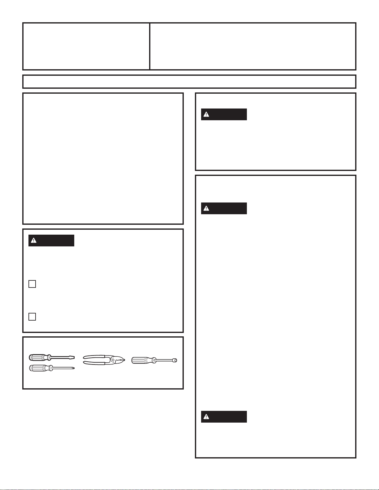
TOOLS NEEDED
Wire cutter/stripper
Flat blade and Phillips
Head Screwdrivers
1/4” Nutdriver
FOR YOUR SAFETY
WARNING
switch power off at service panel and lock the
service disconnecting means to prevent power from
being switched on accidentally. When the service
disconnecting means cannot be locked, securely
fasten a prominent warning device, such as a tag, to
the service panel.
Before beginning the installation,
POWER SUPPLY
IMPORTANT – (Please read carefully)
WARNING
APPLIANCE MUST BE PROPERLY GROUNDED.
Remove house fuse or open circuit breaker before
beginning installation.
Do not use an extension cord or adapter plug with
this appliance. Follow National Electrical Codes or
prevailing local codes and ordinances.
Electrical supply
These vent hoods must be supplied with 120V, 60Hz,
and connected to an individual, properly grounded
branch circuit, and protected by a 15 or 20 amp circuit
breaker or time delay fuse.
• Wiring must be 2 wire with ground.
• If the electrical supply does not meet the above
requirements, call a licensed electrician before
proceeding.
• Route house wiring as close to the installation
location as possible in the ceiling or wall.
• Connect the wiring to the house wiring in
accordance with local codes.
Grounding instructions
The grounding conductor must be connected to
a ground metal, permanent wiring system, or an
equipment-grounding terminal or lead on the hood.
FOR PERSONAL SAFETY, THIS
WARNING
equipment-grounding conductor can result in a risk
of electric shock. Check with a qualified electrician
or service representative if you are in doubt whether
the appliance is properly grounded.
The improper connection of the
31-11120-1 09-17 GEA
Page 2
Installation Instructions
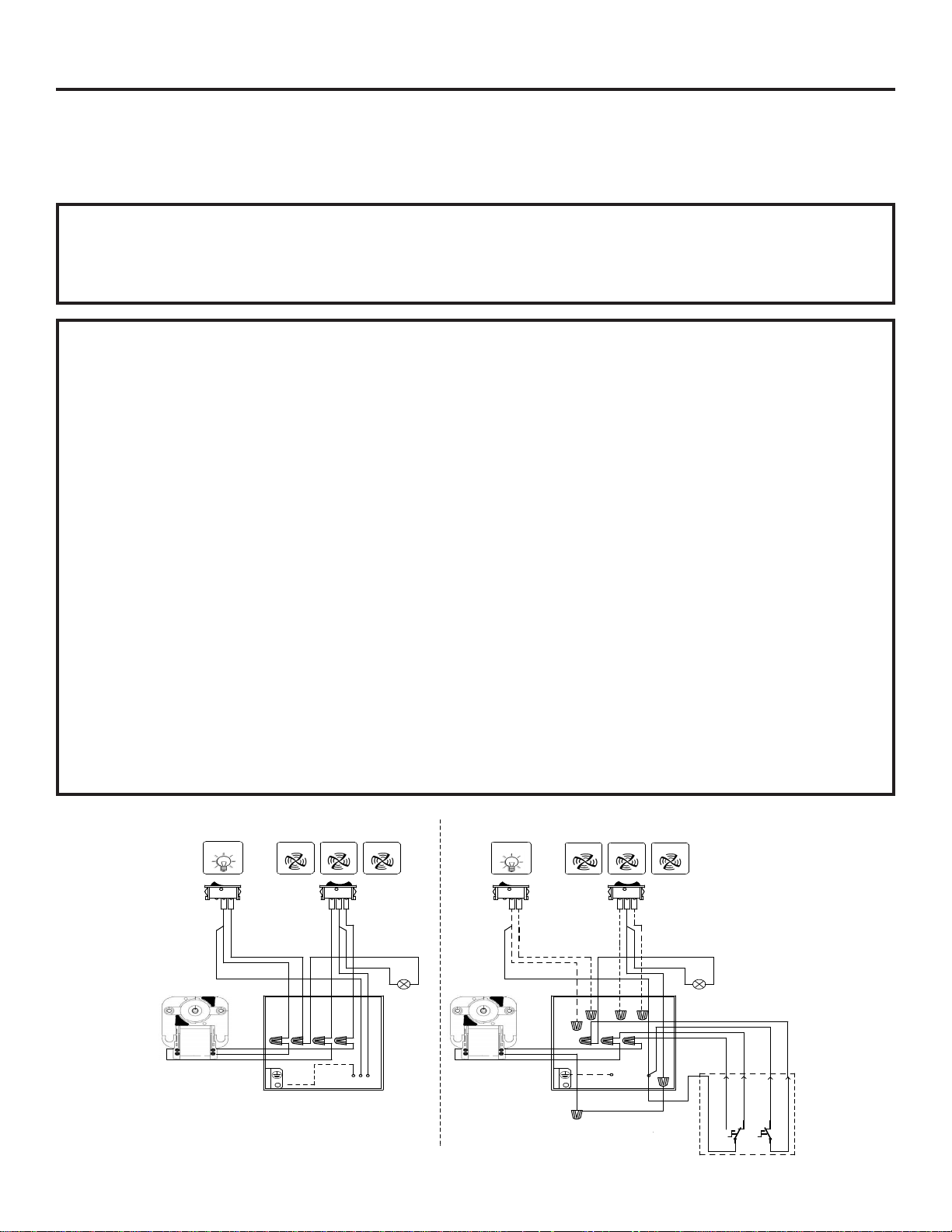
CONTROL
Before getting started, check the wiring diagram number on your hood to make sure
these install instructions apply to your model
CONNECTION METHOD FOR JVX3240 AND JVX3300
PARTS NEEDED
■ 2-Position and 3-Position wall switches.
■ Electrical wire to connect to wall switch in accordance
with local codes.
This connection method allows full control of the range hood using wall switches. However, the rocker switch on the
range hood will be disconnected if this method is used for connection of range hood to wall switch.
Step 1: To establish connection of hood fan to wall
switch, locate the hood junction box and remove its cover.
Step 2: Disconnect the pink wire in the junction box
coming from the motor from the red wire coming from
3-position rocker switch on the range hood. Cap the red
wire coming from 3-position rocker using appropriate
size wire nut.
Step 3: Connect the pink wire in the junction box
coming from the motor to a 3-position wall switch. This
will allow control of high fan speed.
Step 4: Disconnect the grey wire in the junction box
coming from the motor from the black wire coming
from 3-position rocker switch on the range hood. Cap
the black wire coming from 3-position rocker using
appropriate size wire nut.
Step 5: Connect the grey wire in the junction box
coming from the motor to a 3-position wall switch. This
will allow control of low fan speed.
Step 6: Connect a black wire from hot on 3 position wall
switch for fan to the black hot wire in the junction box.
■ Wire nuts. Use appropriate wire nuts for size of the
electrical wire.
■ 18 gage white wire.
Step 7: Disconnect the orange wire in the junction box
from the white wire coming from the motor and cap the
orange wire using appropriate size wire nut.
Step 8: Connect an 18 gage white wire to the white wire
coming from the motor using appropriate size wire nut
at one end. At the other end connect the 18 gage white
wire to the neutral white wire in the junction box using
appropriate size wire nut.
Step 9: To establish connection of hood lights to wall
switch, connect a black wire from hot on 2 position wall
switch for light to the black hot wire in the junction box.
Step 10: Disconnect the violet wire in the junction box
coming from the lamps from the violet wire coming
from 2 position rocker switch on the range hood. Cap
the violet wire coming from 2 position rocker using
appropriate size wire nut.
Step 11: Connect the violet wire in the junction box
coming from the lamps to the 2 position wall switch.
Step 12: Re-install the junction box cover using the
screws.
HOOD INTERNAL CONTROL
0
MOTOR
C30 DX
1
3
1
2
VLT
BLK
ORG
WIRING
BOX
GREY
WHT
PINK
ORG
1
OFF
3
1
2
RED
WHT
WHT
RED
VLT
VLT
BLK
2
BLK
MOTOR
C30 DX
VLT
WHT
LAMP
BLK
WHT
LINE
120Vac
60Hz
Wiring Diagram 991.0438.344
HOOD EXTERNAL CONTROL
0
1
3
1 2
VLT
BLK
ORG
WIRING
BOX
GREY
WHT
PINK
ORG
1
OFF
3 1 2
RED
VLT
WHT
LINE
120Vac
60Hz
WHT
2
BLK
BLK
WHT
WHT
LAMP
COM S2GS1
MOTOR
CONTROL
EXTERNAL
VLT
SPEED2
SPEED1
LIGHT
CONTROL
L
LIGHT
L
LIGHT
2 31-11120-1
Page 3

Installation Instructions
CONNECTION METHOD FOR JVX5305 AND JVX5365
PARTS NEEDED
■ 2-Position wall switch - Qty (2).
■ Electrical wire to connect to wall switch in accordance
with local codes.
This connection method allows switching fan and lights on or off on the range hood using wall switch only. The
rocker switch on the range hood will function and must be kept in on position to allow control of range hood using
wall switch. For fan, the wall switch will turn the fan to speed pre-selected on range hood rocker.
Step 1: To establish connection of hood fan to wall
switch, locate the hood junction box and remove its cover.
Step 2: Remove the access panel in the hood to access
the wiring attached to the range hood rockers.
Step 3: Connect the black wire in the junction box
coming from the fan range hood rocker to 2 position wall
switch.
Step 4: Run power to the 2 position wall switch to
control the fan using wall switch.
Step 5: To establish connection of hood lights to wall
switch, cut the black wire coming from the light range
hood rocker to the middle connector on fan range hood
rocker and cap the end attached to the fan range hood
rocker using appropriate size wire nut.
■ Wire nuts. Use appropriate wire nuts for size of the
electrical wire.
■ 18 gage black wire.
Step 6: Connect a black 24” min. length 18 gage wire to
the black wire that was cut coming from the light range
hood rocker using appropriate size wire nut. Run the
black wire through the conduit into the junction box to
make sure the wire is not exposed to any sharp edges.
Step 7: Connect the black wire added into the junction
box to 2 position wall switch.
Step 8: Run power to the 2 position wall switch to
control the lights using wall switch.
Step 9: Re-install the access panel and junction box
cover using the screws.
HOOD INTERNAL CONTROL
0
1
1b 1a
1
BLK
VLT
BLK
WHT
RED
BLK
WHT
RED
(WHT-GRY)
M8/35 2V
(BLU)
WIRING BOX
1
OFF
1b
1b 1 1a 1b 1 1a 1b 1 1a
BLK
RED
BLK
BLK
HT
WHT
W
TE N
LINE
120Vac 60Hz
2
BLK
F
LAMP
LAMP
HOOD EXTERNAL CONTROL
1
1
0
BLK
VLT
VLT
BLK
WHT
RED
BLK
WHT
RED
(WHT-GRY)
M8/35 2V
WIRING BOX
(BLU)
OFF
RED
BLK
BLK
BLK
WHT
WHT
2
G
LINE
120Vac
60Hz
BLK
BLK
LAMP
LAMP
VLT
EXTERNAL
CONTROL
ON-OFF
ON-OFF
MOTOR
Wiring Diagram 991.0438.625
31-11120-1 3
LIGHTING
Page 4

Notes
4 31-11120-1
 Loading...