

Page 1
I stallatio
!
Z
Pyramid Wall
Chimney Vent Hoods
I structio s
[_ "If you have questions, call 800.GE.CARES (800.432.2737) or visit our website at: GEAppliances.com"
BEFORE YOU BEGIN
Read these instructions completely and
carefully.
oIMPORTANT - Savetheseinstructions
for local inspector's use.
" IMPORTANT - Observe all governing
codes and ordinances.
, Note to Installer- Be sure to leave these
instructions with the Consumer.
, Note to Consumer - Keep these instructions
for future reference.
, Skill level - Installation of this vent hood
requires basic mechanical and electrical skills.
, Completion time - Approximately 1 to 3 hours
, Proper installation is the responsibility of the
installer.
, Product failure due to improper installation is
not covered under the Warranty.
^_CAUTION: Due to the weight and size of
these vent hoods and to reduce the risk of
personal injury or damage to the product, TWO
PEOPLE ARE REQUIRED FOR PROPER
INSTALLATION.
JVW5301, JVW5361
kLW_III_i I I_i£._: TO REDUCE THE RISK
OF FIRE, ELECTRIC SHOCK OR INJURY TO
PERSONS, OBSERVE THE FOLLOWING:
A. Installation work and electrical wiring
must be done by qualified person(s) in
accordance with all applicable codes and
standards, including fire-rated construction.
B. Sufficient air is needed for proper
combustion and exhausting of gases
through the flue (chimney) of fuel burning
equipment to prevent back drafting. Follow
the heating equipment manufacturer's
guidelines and safety standards such
as those published by the National Fire
Protection Association (NFPA), the
American Society for Heating, Refrigeration
and Air Conditioning Engineers (ASHRAE)
and the local code authorities.
C.
When cutting or drilling into wall or ceiling,
do not damage electrical wiring and other
hidden utilities.
U.
Ducted fans must always be vented to the
outdoors.
E.
Turn off breaker to adjacent rooms while
working.
A, ,,,^,-., ,,,, ,., ,,-.
LLW/41Ii_ilI_i_: TO REDUCE THE RISK
OF FIRE, USE ONLY METAL DUCT WORK.
I""
I-"
!
O
Z
!
Z
(.n
-q
;x)
C
!
O
Z
{,t}
FOR YOUR SAFETY:
WARNING: Before beginning the
installation, switch power off at service panel and
lock the service disconnecting means to prevent
power from being switched on accidentally.
When the service disconnecting means cannot
be locked, securely fasten a prominent warning
device, such as a tag, to the service panel.
(991.0364.803 rev2) 31-10983-1 04-15 GE
Page 2
Z
O
g
Installation Preparation
Z
O
i
_J
_J
Z
i
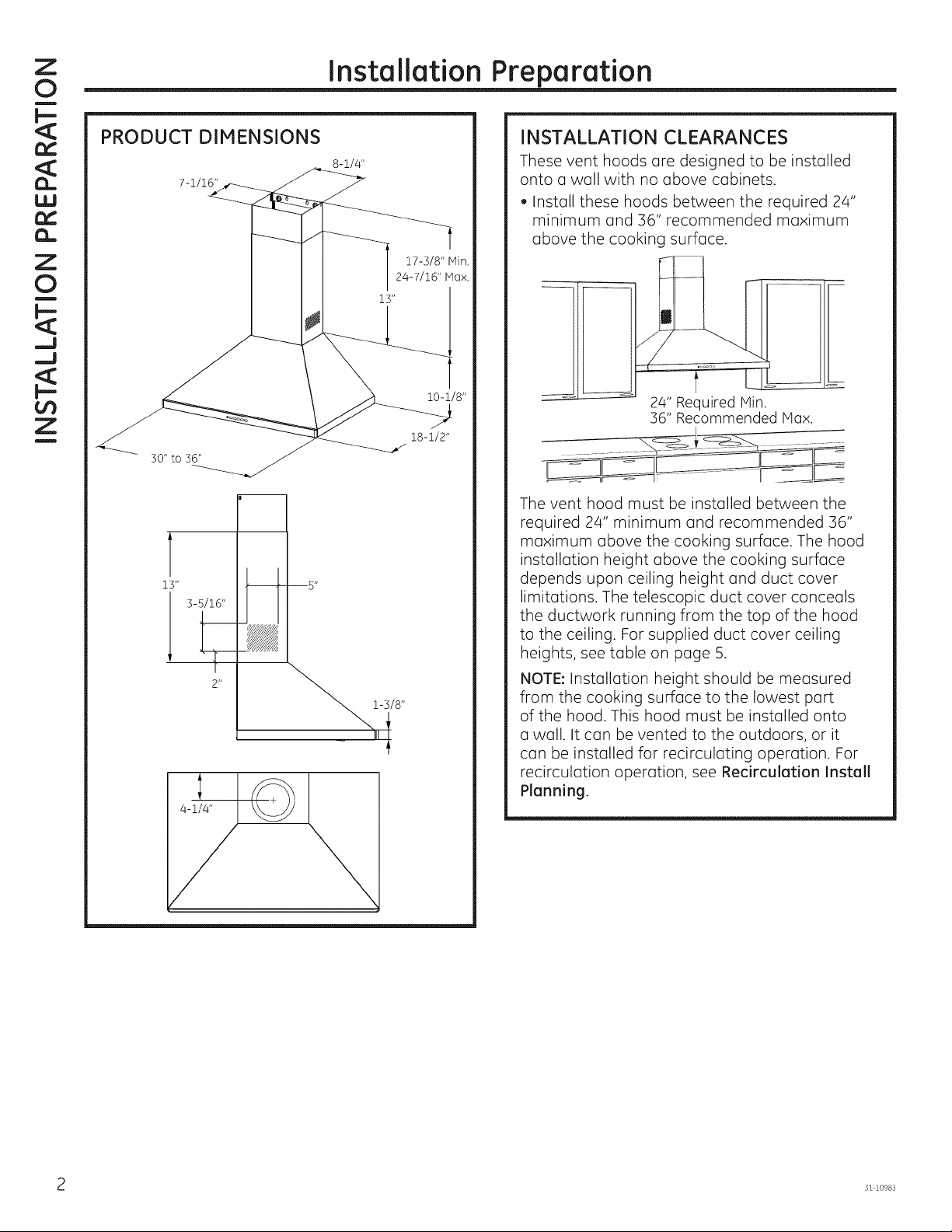
PRODUCT DIMENSIONS
7-1/16"
T
13"
3-5/16"
• , 5"
2"
8-i/4"
INSTALLATION CLEARANCES
These vent hoods are designed to be installed
onto a wall with no above cabinets.
. Install these hoods between the required 24"
minimum and 36" recommended maximum
above the cooking surface.
I
The vent hood must be installed between the
required 24" minimum and recommended 36"
maximum above the cooking surface. The hood
installation height above the cooking surface
depends upon ceiling height and duct cover
limitations. The telescopic duct cover conceals
the ductwork running from the top of the hood
to the ceiling. For supplied duct cover ceiling
heights, see table on page 5.
NOTE: Installation height should be measured
from the cooking surface to the lowest port
of the hood. This hood must be installed onto
a wall. It can be vented to the outdoors, or it
can be installed for recirculating operation. For
recirculation operation, see Recirculation Install
Planning.
24" Required Hin.
36" Recommended Hax.
31 10983
Page 3
Installation Preparation
!
Z
ADVANCE PLANNING
Duct Install Planning
. This hood is designed to be vented vertically
through the ceiling. Use a 6" round duct. Use
locally supplied elbows to vent horizontally
through the rear wall.
. Use metal ductwork only.
. Determine the exact locution of the vent hood.
. Plan the route for venting exhaust to the
outdoors. To maximize the ventilation
performance of the vent system:
1. Minimize the duct run length and number of
transitions and elbows.
2. Maintain a constant duct size.
3.Seal all joints with duct tape to prevent any
leaks.
4. Do not use any type of flexible ducting.
. Install a wall cap or roof cap with damper
at the exterior opening. Purchase the wall or
roof cap and any transition and length of duct
needed in advance.
. When applicable, install any makeup
(replacement) air system in accordance
with local building code requirements. Visit
GEAppliances.com for available makeup air
solutions.
Recirculation Install Planning
A recirculation duct (included) and two
charcoal filters (not included) are necessary for
recirculation installation.
Power Supply Planning
The location of the power supply connection is
called out in the Prepare the Wall section on
page 6.
POWER SUPPLY
IMPORTANT- (Please read carefully}
AWARNING:
FOR PERSONAL SAFETY,THIS APPLIANCE MUST BE
PROPERLYGROUNDED.
Remove house fuse or open circuit breaker
before beginning installation.
Do not use an extension cord or adapter plug
with this appliance. Follow National Electrical
Codes or prevailing local codes and ordinances.
Electrical supply
These vent hoods must be supplied with 120V,
60Hz, and connected to an individual, properly
grounded branch circuit, and protected by a 15
or 20 amp circuit breaker or time delay fuse.
. Wiring must be 2 wire with ground.
. If the electrical supply does not meet the above
requirements, call a licensed electrician before
proceeding.
. Route house wiring as close to the installation
location as possible in the ceiling or wall.
. Connect the wiring to the house wiring in
accordance with local codes.
Grounding instructions
The grounding conductor must be connected to
a ground metal, permanent wiring system, or an
equipment-grounding terminal or lead on the hood,
,WARNING: The improper connection
of the equipment-grounding conductor can result
in a risk of electric shock. Check with a qualified
electrician or service representative if you are in
doubt whether the appliance is properly grounded.
!
0
Z
m
!
0
Z
31 10983 3
Page 4
Z
0
g
Installation Preparation
Z
0
i
_J
_J
Z
i
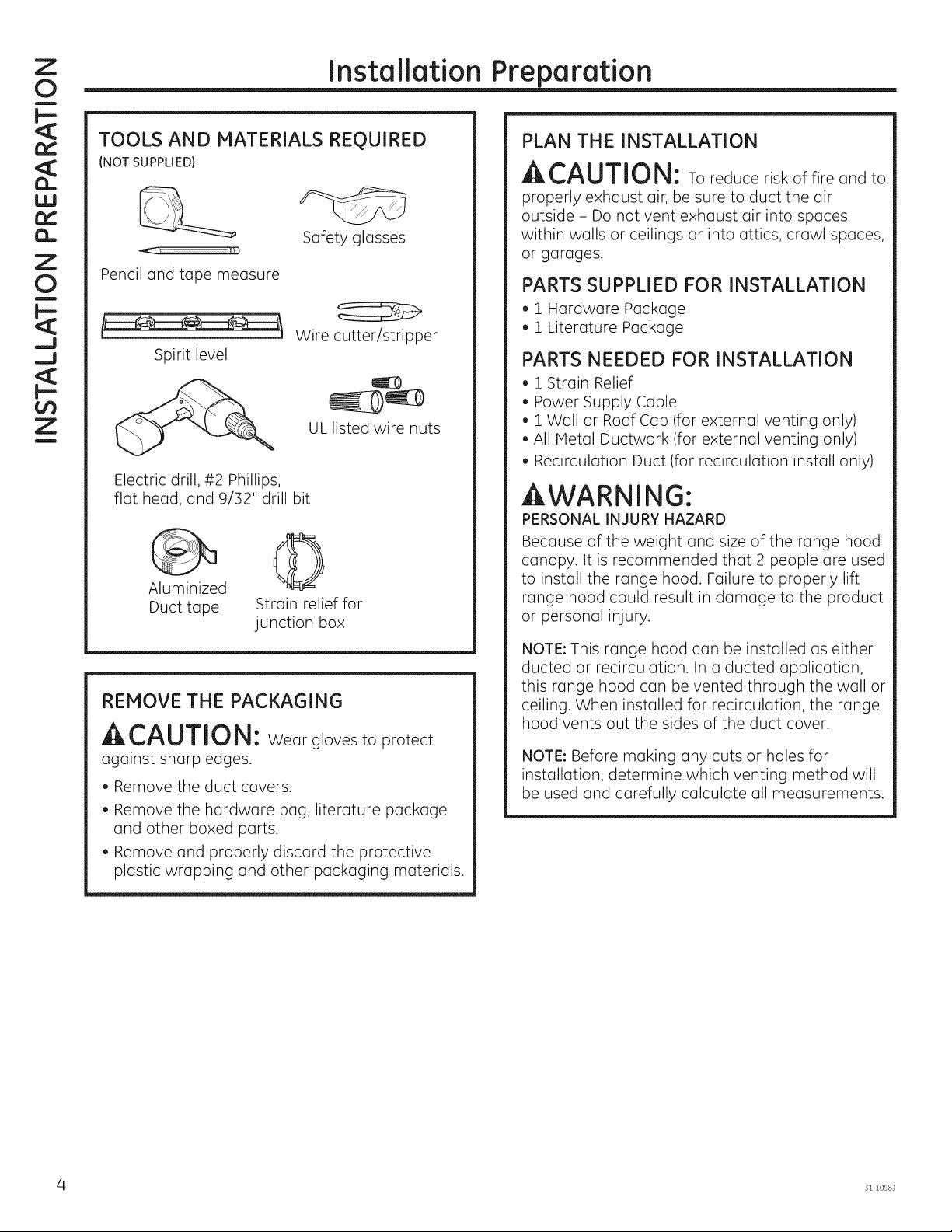
TOOLS AND MATERIALS REQUIRED
(NOT SUPPLIED)
Safety glasses
Pencil and tape measure
Wire cutter/stripper
Spirit level
UL listed wire nuts
Electric drill, #2 Phillips,
flat head, and 9/32" drill bit
Duct tape Strain relief for
junction box
REMOVE THE PACKAGING
A CAUTION: Wear gloves to protect
against sharp edges.
. Remove the duct covers.
, Remove the hardware bag, literature package
and other boxed parts.
, Remove and properly discard the protective
plastic wrapping and other packaging materials.
PLAN THE INSTALLATION
ACAUTION: To reduce risk of fire and to
properly exhaust air, be sure to duct the air
outside - Do not vent exhaust air into spaces
within walls or ceilings or into attics, crawl spaces,
or garages.
PARTS SUPPLIED FOR INSTALLATION
,1 Hardware Package
,1 Literature Package
PARTS NEEDED FOR INSTALLATION
,1 Strain Relief
, Power Supply Cable
, i Wall or Roof Cap (for external venting only)
, All Metal Ductwork (for external venting only)
, Recirculation Duct (for recirculation install only)
WARNING:
PERSONAL INJURY HAZARD
Because of the weight and size of the range hood
canopy. It is recommended that 2 people are used
to install the range hood. Failure to properly lift
range hood could result in damage to the product
or personal injury.
NOTE: This range hood can be installed as either
ducted or recirculation. In a ducted application,
this range hood can be vented through the wall or
ceiling. When installed for recirculation, the range
hood vents out the sides of the duct cover.
NOTE: Before making any cuts or holes for
installation, determine which venting method will
be used and carefully calculate all measurements.
- 31 10983
Page 5
Installation Preparation
!
Z
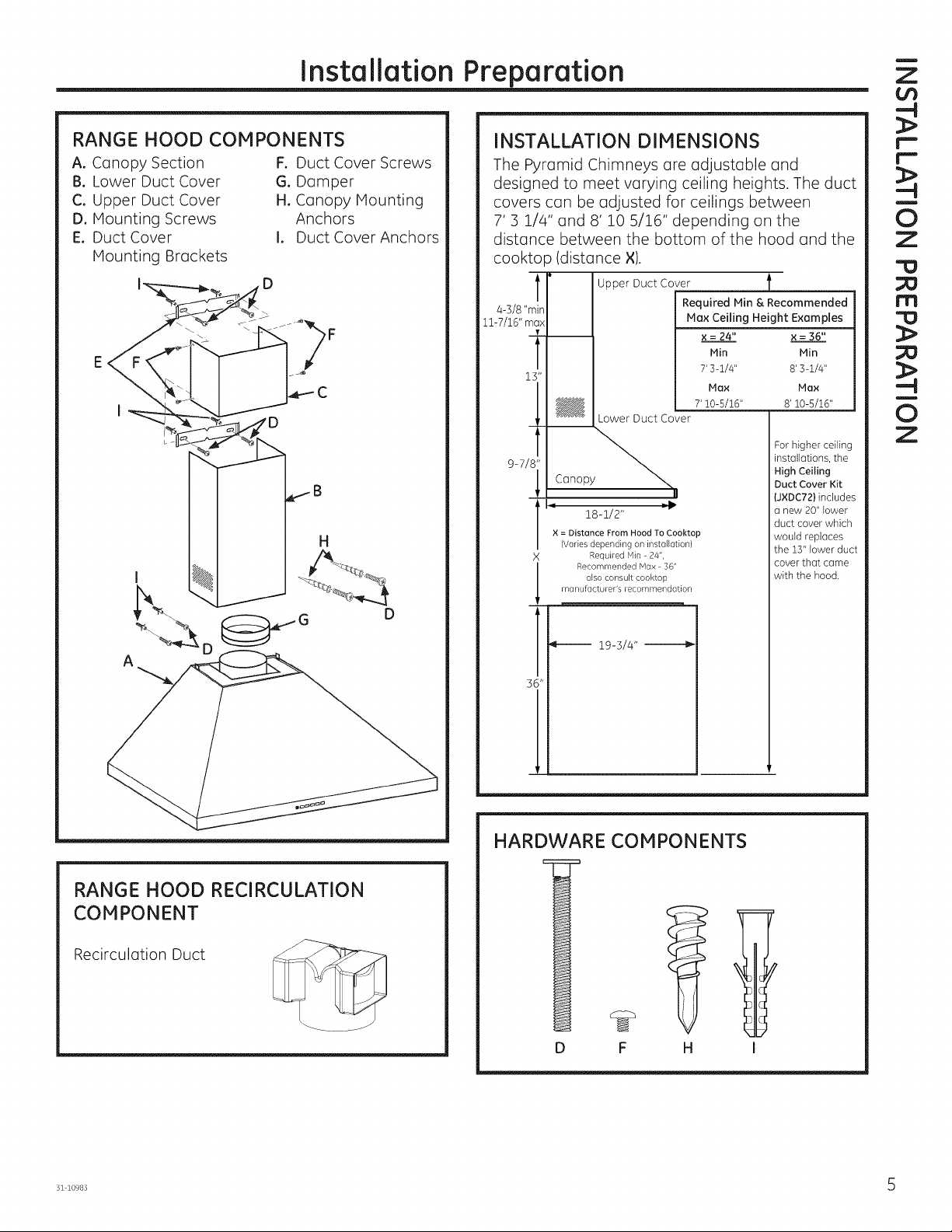
RANGE HOOD COMPONENTS
A. Canopy Section
B. Lower Duct Cover
C. Upper Duct Cover
D. Haunting Screws
E. Duct Cover
Haunting Brackets
F. Duct Cover Screws
G. Damper
H. Canopy Haunting
Anchors
I. Duct Cover Anchors
D
INSTALLATION DIMENSIONS
The Pyramid Chimneys are adjustable and
designed to meet varying ceiling heights. The duct
covers can be adjusted for ceilings between
7' 3 1/4" and 8' 10 5/16" depending on the
distance between the bottom of the hood and the
cooktop (distance X).
T ,
4-3/8 "min
11-7/16" ma_
l L
13"
C
9-7/
T
X
Upper Duct Cover
Required Min & Recommended
Lower Duct Cover
Canopy_
II
18-1/2"
X = Distance From Hood To Cooktop
(Varies depending on installation)
Required Min - 24%
Recommended Max 36"
also consult cooktop
manufacturer's recommendation
Max Ceiling Height Examples
x = 24" x = 36"
Min Min
7' 3-1/4" 8' 3-1/4"
Max Max
7' 10-5/16" 8' 10-5/i6"
For higher ceiling
installations, the
High Ceiling
Duct Cover Kit
(JXDC72) includes
a new 20" lower
duct cover which
would replaces
the 13" lower duct
coverthatcame
with the hood
r'-"
!
0
Z
"0
rn
!
0
Z
RANGE HOOD RECIRCULATION
COMPONENT
Recirculation Duct
19-3/4"
HARDWARE COMPONENTS
¢
(
(
(
l
%
D
F
H
D c
Dr
D(
I
31 10983 5
Page 6

Z
O
g
Installation Preparation
Z
O
i
_J
_J
¢t)
Z
i
PREPARE THE WALL
Hood Body and Power Supply
1. Put a protective covering over the surface
below the location of the hood to protect from
dirt and/or damage.
2. Determine and mark the centerline on the wall
(draw line up to the ceiling)where the range
hood will be installed. Based on the ceiling
height, determine the distance 24" required min,
36" recommended max (×)needed between the
cooking surface (B)and the bottom of the hood.
To this distance, add 7" and draw a horizontal
line (A) about 24" long centered on the vertical
centerline (C).
3. Hark 2 points on each side of the horizontal line
(A),5-1/2" from the vertical centerline (C).Drill the
canopy mounting anchors into the wall at the
markings. Install the 2 mounting screws into the
anchors, leaving a 1//4" gap between the wall
and the back of the screw head. (You will place
the hood body onto these screw heads.)
/4. Draw a second horizontal line (D)that is 1-1//4"
added from the × distance. Draw a third
horizontal line (E)that is/4-5/16" added from the
× distance.
.
Hark 2 points on each side of the horizontal
line (D), 7-7/8" from the vertical centerline (C).
Drill the 2 holes for installation with a 9/32" drill
bit, and insert the duct cover anchors.
.
Determine and mark where the hole will be
drilled for the power supply cable to be run
through the wall. lark a point on the left side
of the horizontal line (E),6-1//4" from the vertical
centerline (C).Drill a 1-1//4" hole at this mark.
I
I
I
/
/ D
L
r
/
/ A
/
/ E
i- z-7/s"_ z-7/s"--_ ', 4-5/16"\_
+
5-I/2"i 5-I/2" \
, \
Duct Covers
1. Place one of the duct cover brackets against
the wall so that its top edge is 1/16" from the
ceiling and level. Align the center notches of
the bracket and the centerline (C) and mark
the centers of the bracket holes. Remove
the bracket to drill the 2 holes for installation
with a 9/32" drill bit, and insert the duct cover
anchors. Place the bracket back on the wall
and install the 2 mounting screws into the
anchors. Tighten screws.
2. Place the other duct cover bracket on the
wall so that its top edge is 10-1/2" from the
ceiling and level. Align the center notches of
the bracket and the centerline (C) and mark
the centers of the bracket holes. Remove
the bracket to drill the 2 holes for installation
with u 9/32" drill bit, and insert the duct cover
anchors. Place the bracket back on the wall
and install the 2 mounting screws into the
anchors. Tighten screws.
Ceiling
1/16"
oF _- o]
r
/
/
/
/
/
/
i
i
i
i
\
\
\
\
\
\
t
10-1/2"
1
c! x
'!
1
i i__ii/4, .
3
31 10983
Page 7

Installation Instructions
!
Z
¢/9
PREPARE HOOD FOR INSTALLATION
i.
Remove the grease filters from the unit and
set aside. The grease filters are removed
by pressing the handle
in front of the filter.
When replacing, make
sure that the filters are
properly positioned with
the handles in front and
visible.
2. Remove and properly discard the protective
plastic wrapping from the hood and grease
filters.
3. Remove junction box cover.
Vented Installations
1. Securely press damper on top of the exhaust
opening. Check that the damper opens freely.
2. Go to Mount the Range Hood in this section.
Non-vented Irecirculation)Installations
NOTE: Recirculation duct (included) and charcoal
filters JXCF72 (not included) are required. The
damper is not installed on the unit with
recirculation installations.
1. Install the non-vented (ductless) recirculation
duct (A)supplied with the vent hood,
Non-vented {recirculation)Installations
(Continuedl
2. Check that the recirculation duct is in the correct
orientation with the hole towards the front of
the hood. Fit the recirculation duct over the vent
exhaust outlet (B)and push down to seat on the
outlet.
3. Go to Mount the Range Hood in this section.
NOTE:
Hole must
be facing
toward front
of hood.
MOUNT THE PYRAMID RANGE HOOD
.
Install the range hood body by placing the
hood key holes over the mounting screws. Feed
the power supply cable through the electrical
knockout. Tighten the mounting screws.
Mounting
Screw Slots
I--
I--
!
0
Z
!
Z
¢/9
-t
C
-4
!
0
Z
B
2. Insert 2 mounting screws into the 2 duct cover
anchors (installed on line D in Preparing the
Wall section)located in the slots on the back
surface of the hood. Secure tightly.
3. Connect the house ducting to the damper
on the hood body if ducted install. Seal all
connections with duct tape.
NOTE: If recirculation installation, skip to Step 4
and proceed.
4. Install the upper duct cover. __-
Slightly spread the sides of . _ .....
the cover apart and hook
them behind the duct cover
mounting brackets. Attach
the cover to the brackets
with 4 duct cover screws.
31 10983 7
Page 8

Z
O
i
U
=)
Z
i
Z
O
g
_J
_J
Installation Instructions
ELECTRICAL CONNECTION
1. Connect the Power Supply Cable to the range
hood. Attach the white lead of the power supply
to the white lead of the range hood (A) with a
wire nut (C).Attach the black lead of the power
supply to the black lead of the range hood
(B)with a wire nut (C).Connect the green (D)
ground wire under the green grounding screw,
2. Replace the junction box cover.
C
FINISH THE INSTALLATION
(Continued)
3. Using a flathead screwdriver, lift up the tabs on
the top of the canopy.
Tabs
Z
i
FI
1.
D
NISH THE INSTALLATION
For recirculation installation only: Attach the
CHARCOAL FILTERS(not included)to both sides
of the blower. To do this, place the side of the
charcoal filter with the tabs against the side
of the blower. Align the double lines on the
charcoal filter with the "unlocked" symbol on
the blower. Push and twist downward until the
double lines align with the "locked" symbol on
the blower, Repeat on other side with second
filter,
. To install the lower duct cover:
, Use a flat head screwdriver to push the
two tabs forward on the lower duct cover.
, Angle the duct cover to slide the tabs
under the ledge of the hood body. Seat the
back of the duct cover on the top of the
range hood between the edges and tabs.
\
For recirculation and ducted installation:
2. Replace the grease filters.
7 J
J J
.
Turn the power supply on. Turn on blower
and light. If the range hood does not operate,
check that the circuit breaker is not tripped
or the house fuse blown. If the unit still does
not operate, disconnect the power supply and
check that the wiring connections have been
made properly.
31 10983
Page 9

I struccio es
i
Z
Campanas de Ventilaci6n de Chimeneas
de Pared Pir6mide
de i stal ci6n
r_ zPreguntas? Llame al 800.GE.CARES (800.432.2737)o visite nuestro sitio Web en: GEAppliances.com
ANTES DE COMENZAR
Lea estas instrucciones por completo y con
detenimiento.
.IMPORTANTE - Guardeestas
instrucciones para el uso de inspectores
locales.
.IMPORTANTE - Cumplacontodoslos
c6digos y ordenanzas vigentes.
, Nota al instalador - AsegOrese de dejar estas
instrucciones con el Consumidor.
, Note al consumidor - Conserve estas
instrucciones para referencia futura.
, Nivel de capacidad - La instalaci6n de esta
campana de ventilaci6n requiere capacidades
mec6nicas y el6ctricas basicas.
, Tiempo de finalizad6n - Aproximadamente
de 1 a 3 horas.
, El instalador tiene la responsabilidad de
efectuar una instalaci6n adecuada.
, La Garantia no cubre las fallas del producto
debido a una instalaci6n incorrecta.
A
I"KI_LJAUL, IUI_I" Debido al peso
y tama_o de estas campanas de ventilaci6n y
para reducir el riesgo de lesiones personales o
da_os al producto, SE NECESITAN DOS
PERSONAS PARA REALIZAR UNA INSTALACI6N
CORRECTA.
PARA SU SEGURIDAD:
JVW5301, JVW5361
A ^nl nrnmrk|r,^
_UVE_IEI_I_: PARA REDUCIR EL
RIESGO DE INCENDIO, DESCARGA ELECTRICA
O LESIONES A PERSONAS, CUMPLA CON LOS
SIGUIENTES PUNTOS:
A. El trabajo de instalaci6n y el cableado
electrico deben set realizados pot una
persona(s) calificada de acuerdo con todos los
c6digos y estandares aplicables, incluyendo
construcciones resistentes al fuego.
B. Es necesario contar con suficiente
cantidad de aire para una combusti6n
y salida de gases adecuadas a traves
del conducto (chimenea) del equipo de
consumo de combustible, a fin de evitar
rafagas de aire. Siga las pautas del
fabricante del equipo de calefacci6n y
los estandares de seguridad, tales como
aquellos publicados por la Asociaci6n
Nacional de Protecci6n contra Incendios
(National Fire Protection Association,
NFPA), la Sociedad Estadounidense
para la Calefacci6n (American Society for
Heating), los Ingenieros de Refrigeraci6n y
Acondicionadores de Aire (Refrigeration and
Air Conditioning Engineers, ASHRAE) y las
autoridades de los c6digos locales.
C. AI cortar o perforar una pared o un
cielorraso, no daBe el cableado electrico y
de otros servicios ocultos.
D,
Los ventiladores con conducto siempre
deben contar con ventilaci6n hacia el exterior.
E.
Desconecte el disyuntor de habitaciones
adyacentes mientras este trabajando.
C
N
N
=
i
O
Z
m
m
i
Z
r-
i
O,
Z
,Jt/'_UVCK|EI_IL, I_: Antes de comenzar
la instalaci6n, desconecte la energia del panel de
servicio y bloquee los medios de desconexi6n
para evitar el accionamiento de la energia de
manera accidental. Cuando los medios de
desconexi6n de servicio no pueden bloquearse,
coloque sobre el panel de servicio un dispositivo
de advertencia bien visible, como una etiqueta.
A ^,-,1 ,,--,-,,-,-,-,,,,-,,^
'm_ h_L,/Vi:=I!,Ii::I'_L, Ih\: A FIN DE
REDUClR EL RIESGO DE INCENDIOS, USE
SOLO CONDUCTOS DE METAL.
(991.0364.803 rev2) 31-10983-1 04-15 GE
Page 10

Z
"0
i
U
_J
l=-
¢t)
Z
i
_J
<_
Z
"0
i
U
Preparaci6n para la instalaci6n
DIMENSIONES DEL PRODUCTO
8-1/4"
7-1/16"
17-3/8" Hin,
24-7/16" Max.
ESPACIO DE INSTALACI6N
Estascampanas de ventilaci6n est6n disefladas
para ser instaladas en una pared sin gabinetes
superiores.
. Instale estas campanas entre el minimo
requerido de 24"y el m6ximo recomendado de
36" sobre la superficie de cocci6n.
24" Required Hin.
36" Recommended Hax.
1.1.1
T
13"
3-5/16"
• , 5"
La campana de ventilaci6n debe set instalada
entre el minimo requerido de 24" y el m6ximo
recomendado de 36" sobre la superficie de
cocci6n. La altura de instalaci6n de la campana
sobre la superficie de cocci6n depende de la
altura del cielorraso y las limitaciones de la
cubierta del conducto. La cubierta plegable
oculta los conductos que van desde la parte
superior de la campana hasta el cielorraso. Para
las alturas de cielorraso de las cubiertas de
conductos, consulte la tabla de la p6gina 5.
NOTA:La altura de instalaci6n debe medirse
desde la superficie de cocci6n hasta la parte
m6s baja de la campana. Esta campana debe
ser instalada sobre una pared. Puedecontar
con ventilaci6n hacia el exterior, o puede
set instalada para un funcionamiento con
recirculaci6n. Para un funcionamiento con
recirculaci6n, consulte la Planificaci6n para la
Instalaci6n con Recirculaci6n.
31 10983
Page 11

Preparaci6n para la instalaci6n
!
Z
PLANIFICACI6N PREVIA
Planificaci6n para la Instalaci6n con Conducto
, Esta campana est6 diseBada para ventilarse
en forma vertical a trav6s del cielorraso.
Use un conducto circular de 6". Utilice codos
suministrados en forma local para ventilaci6n
horizontal a trav6s de la pared trasera.
, Determine la ubicaci6n exacta de la campana
de ventilaci6n.
. Planifique el recorrido de la salida de ventilaci6n
hacia el exterior. A fin de maximizar el
rendimiento de la ventilaci6n del sistema de
ventilaci6n:
1. Hinimice la Iongitud del conducto y el n0mero
de transiciones y codos.
2. Hantenga un tama_o de conducto constante.
3.Selle todas lasjuntas con cinta para
conductos a fin de evitar p@didas.
4. No utilice conductos flexibles de ning0n tipo.
. Instale una cubierta de pared o casquete
de techo con un regulador de tiro en la
abertura exterior. Solicite por adelantado la
cubierta de pared o el casquete de techo y
cualquier transici6n o Iongitud de conducto
necesarios.
, Cuando corresponda, instale un sistema de
reposici6n (reemplazo) de aire de acuerdo con
los requisitos del c6digo local de construcci6n.
Para acceder a soluciones de aire disponibles,
visite GEAppliances.com.
Planificaci6n de Instalaci6n con Recirculaci6n
Un conducto de recirculaci6n (incluido) y un filtro
de carb6n (no incluido) son necesarios para la
instalaci6n con recirculaci6n.
Planificaci6n del Suministro de Corriente
La ubicaci6n de la conexi6n del suministro
de corriente es indicada en la secci6n de
Preparaci6n de la Pared en la p6gina 6.
SUMINISTRO DE ENERGIA
IMPORTANTE - (Tenga a bien leer cuidadosamente)
AADVERTENCIA:
PARASEGURIDAD PERSONAL, ESTEAPARATO
DEBECONECTARSE A TIERRA DE HANERA
ADECUADA.
Quite el fusible o abra el interruptor de circuitos
antes de comenzar la instalaci6n.
No utilice un cable de extensi6n o un enchufe
adaptador con este artefacto. Siga los C6digos
EI6ctricos Nacionales o c6digos y ordenanzas
locales vigentes.
Suministro el_ctrico
Estas campanas de ventilaci6n deben contar
con un suministro de Z20V, 60Hz, deben estar
conectadas a un circuito derivado individual con
una adecuada conexi6n a tierra y deben contar
con la protecci6n de un interruptor de circuitos
o un fusible con retraso de 15 o 20 amperios.
. El cableado debe ser de 2 hilos con conexi6n
a tierra.
• Si el suministro el6ctrico no cumple con los
requisitos anteriores, Ilame a un electricista con
licencia antes de continuar.
Dirija el cableado dom6stico Io m6s cerca
posible a la ubicaci6n de la instalaci6n, en el
cielorraso o pared trasera. Vet p6gina 14 para
m6s detalles.
, Conecte el cableado al cableado dom6stico
en cumplimiento con los c6digos locales.
Instrucdones de conexi6n a tierra
El conductor a tierra debe conectarse a un metal
con conexi6n a tierra, un sistema de cableado
permanente o una terminal o conductor de
conexi6n a tierra del equipamiento en la
campana.
r_
r-
!
O
Z
"0
m
"0
!
O
Z
A ADVERTENClA: Unaconex 6n
inadecuada del conductor de conexi6n a tierra
del equipamiento puede provocar un riesgo
de descarga el6ctrica. Consulte a un electricista
calificado o representante de servicio t6cnico
si tiene dudas sobre la correcta conexi6n a tierra
del artefacto.
3i 10983 3
Page 12

Z
"O
i
Preparaci6n para la instalaci6n
_J
I--
Z
i
_J
<1:
Z
"O
i
i.1,1
HERRAMIENTAS Y MATERIALES
REQUERIDOS (NO SUMINISTRADOS)
Gafas de seguridad
L6piz y cinta m6trica
Alicate pelacables
Nivel
Tapones de
alambre aprobados
por UL
Broca el6ctrica con Phillips
N° 2 de cabeza planay
broca de 9/32"
©
Cinta aislante
de aluminio
QUITE EL ENVOLTORIO
A PRECAUCION: Seguantespara
protegerse de los bordes afilados.
, Quite las cubiertas de los conductos.
, Quite la bolsa de piezas, el paquete
de instrucciones y otras piezas en cajas.
, Quite y descarte adecuadamente el envoltorio
pl6stico de protecci6n y otros materiales
de empaque.
Alivio de tensi6n para
la caja de conexiones
PLAN DE INSTALACI6N
J
A PRECAUCION: A fin de reducir
riesgos de incendios y para que el aire salga de
forma apropiada, aseg6rese de que el aire sea
conducido hacia fuera - No ventile el aire de la
salida hacia espacios dentro de paredes o
cielorrasos o 6ticos, espacios muy bajos o garajes.
PIEZAS PROVISTAS PARA LA
INSTALACI6N
, i Paquete de Herramientas
,, 2 Paquete Escrito
PIEZASNECESARIASPARA LA
INSTALACI6N
,1 Amortiguador de Refuerzo
, Cable de Suministro de Corriente
, Una Tapa de Pared o Techo (para ventilaci6n
con conducto @nicamente)
, Toda la Tuberia Het61ica (para ventilaci6n con
conducto @nicamente)
, Conducto de Recirculaci6n (para instalaci6n con
recirculaci6n Onicamente)
ADVERTENCIA:
! RIESGO DE LESIONES PERSONALES
Debido al pesoy tama_o de la base de la
campana extractora. Esrecomendable que
la campana extractora sea instalada por 2
personas. Si la campana no es elevada de forma
correcta, se podr6n producir da_os sobre el
producto o lesiones personales.
NOTA:Estacampana puede ser instalada con
conducto o con recirculaci6n. Enuna aplicaci6n
con conducto, esta campana puede set ventilada a
trav@sde la pared o del cielorraso. AIset instalada
pot recirculaci6n, la campana ventila hacia afuera
los costados de la cubierta del conducto.
NOTA: Antes de realizar cualquier corte o agujero
para la instalaci6n, determine qu6 m@odo de
ventilaci6n ser6 usado y con cuidado calcule
todas las medidas.
- 31 10983
Page 13

Preparaci6n para la instalaci6n
"0
m
COMPONENTES DE LA CAMPANA
EXTRACTORA
A. Secci6n de la Base
B. Cubierta del
Conducto Inferior
C. Cubierta del
Conducto Superior
D. Tornillos de Montaje
E. Soportes de Montaje
de la Cubierta del
Conducto
F. Tornillos de la
Cubierta del
Conducto
G. Regulador
H. Soportes de Hontaje
de la Base de la
Campana
I. Soportes dela
Cubierta del Conducto
H
DIMENSIONES DE INSTALACI6N
LasChimeneas de Pir6mide son ajustables y est6n
disehadas para adaptarse a diferentes alturas de
cielorraso. Lascubiertas de los conductos pueden
set qjustadas para cielorrasos de entre 7' 3 1/4"
and 8' _tO5/16", dependiendo de ladistancia entre
la parte inferior de la campana y la superficie de
cocci6n (distancia ×).
[Vlinde4-3/8"
M6xde 1117/16"
i ,
i
13"
9-7/
X (Varfadependiendode la instalaci6nl
D
36"
' Cubierta del Conducto Superior l
Altura M6ximaRecomendadadeCielorraso
I Cubierta del Conducto Inferior
Dosel
II
I = 18-1/2" -"
× = Distancia Desdela Campana Hasta
la SuperficiedeCocci6n
HinimoRequerido 24%
N6×imoRequerido 36";
tambi6n consulte la recomendaci6n del
fabricante de codnas
19-3/4" JJJ-_
Ejemplosde Altura MinimaRequeriday
×=24" ×=36"
Min. Min
7' 3-1/4" 8' 3-1/4"
M6x. M6x.
7' 10-5/16" 8' i0-5/16"
Para realizar
instalaciones
en cielorrasos
altos, el Kit de
Cubiertas de
Conductos para
Cielorrasos
Altos (J×DC72)
induye una
nueva cubierta
de conductos
)ara 6reas
inferiores de 20"
que reemplaza
a la cubierta de
conductos para
6teas inferiores de
13" incluida con la
campana
!
O,
Z
r-
!
Z
r-
!
O,
Z
A
!
COMPONENTES DE LAS HERRAMIENTAS
(
COMPONENTES DE RECIRCULACI6N
Conductode Recirculaci6n
%
D
31 10983 5
F
(
(
H
D c
DC
D(
I
Page 14

Z
"O
i
Preparaci6n para la instalaci6n
<1:
_J
<1:
l--
¢t)
Z
i
<1:
_J
Z
"O
i
U
PREPARE LA PARED
Cuerpo de la Campana y Suministro de
Corriente
1. Coloqueuna cubiertaprotectorasobre la superficie
debajode la ubicaci6nde la campana,a fin de proteger
de la suciedady/o da_os.
2. Determiney marque la Ifneacentral sobrela pared
(dibujela Ifneahaciaarriba hasta elcielorraso)dondela
campana extractora ser6 instalada.Enbasea la altura
del cielorraso,determinela distanciamfnimarequerida
de 24"y la distancia m6ximarecomendadade 36"(×),
necesariasentre lasuperficiede cocci6n(B)y la parte
inferiorde la campana.A estadistancia,agregue 7"y
dibujeuna Ifneahorizontal(A)deaproximadamente24"
de Iongitudcentrada sobrelaIfneacentral vertical(C).
]. Marque 2 puntos a cada lado de la Ifnea horizontal
(A),a 5 1A"desde la Ihea central vertical. Agujeree los
sostenes de montaje de la parte superior de la pared,
donde se encuentran las marcas. Instale los2 tornillos
de montaje en lossostenes,dejando un espacio de
1A"entre la pared y la parte trasera de la cabeza del
tornillo. (Debecolocar el cuerpo de la campana en las
cabezas de estostornillos).
4. Marque una segunda Ifneahorizontal (D)de 1 _A",
agregada desdela distancia ×.Marque una tercera
Ihea horizontal (D)de4 5/16%agregada desde la
distancia X.
5. Marque 2 puntos a cada lado de la Ifnea horizontal
(D),a 7 7/8" desde la Ifneacentral vertical (C).Haga 2
agujeros para la instalaci6n con una broca de9/32%e
inserte los sostenes de la cubierta del conducto.
6. Determiney marque el lugar donde el agujero ser6
perforado para que el cable de suministro de corriente
pueda pasar a trav6s de la pared. Marque unpunto
del lado izquierdo de la Ifneahorizontal (E),a 6 _A"
desde la Ifnea central vertical (C).Haga un agujero de
1 _A"en esta marca, i
i
i
1- -'
_ 5-I12" \
, \
I
'i t
i I-I/4"
i
cl x
/
/ D
I_
r
/
/ A
/
/ E
i- 7-7/s"_, 7-7/s"--_ ', 4-5/16" _
Cubiertas de Conductos
1. Coloque uno de los soportes de la cubierta del
conducto contra la pared, de modo que su extremo
superior est6 a 1/16" del cielorraso y que quede
nivelado. Alinee las ranuras centrales del soporte
con la Ifnea central (C)y marque los centros de los
agujeros del soporte. Retire el soporte para perforar
2 agujeros para la instalaci6n con una broca de
9/32%e inserte los sostenes de la cubierta del
conducto. Vuelva a colocar el soporte en la pared
e instale los 2 tornillos de montaje en los sostenes.
Ajuste los tornillos.
2. Coloque el otro soporte de la cubierta del conducto
contra la pared, de modo que su extremo superior
est6 a 10-1/2" del cielorraso y que quede nivelado.
Alinee las ranuras centrales del soporte con la Ifnea
central (C)y marque los centros de los agujeros del
soporte. Retire el soporte para perforar 2 agujeros
para la instalaci6n con una broca de 9/32% e inserte
los sostenes de la cubierta del conducto. Vuelva a
colocar el soporte en la pared e instale los 2 tornillos
de montaje en los sostenes. Ajuste los tornillos.
Cielorraso
1/16"
r
/
/
/
/
/
/
L
\
10-1/2"
\
\
\
\
\
T
L
B I
i
'1
i
i
I
L
31 10983
Page 15

Instruccionesde instalaci6n
!
Z
--i
PREPARE LA CAMPANA PARA SU
INSTALACI6N
1. Retire los filtros de grasa de la unidad y deje
los mismos a un lado. Los
filtros de grasa son retirados
presionando la manUa que
se encuentra frente al filtro.
AI realizar el reemplazo,
aseg6rese de que los
filtros est6n correctamente
posicionados con las manUas
en el frente y visibles.
2. Retire y descarte de forma adecuada el envoltorio
protector de pl6stico de la campana y de los filtros
de grasa.
3. Retire la tapa de la caja de empalmes.
InstaJaciones Ventiladas
1. De forma segura, presione el regulador que se
encuentra sobre la abertura del escape. Controle
que el regulador se pueda abrir libremente.
2. Consulte sobre el Montaje de la Campana en esta
secci6n.
Instalaciones sin ventilaci6n (recirculaci6n)
NOTA:Se requiere el conducto de recirculaci6n
(incluido) y los filtros de carb6n JXCF72 (no incluidos).
El regulador no est6 instalado en la unidad con
instalaciones de recirculaci6n.
1. Instale el conducto de recirculaci6n (A)(sin
conducto) suministrado con la campana de
ventilaci6n.
Instalaciones sin ventilaci6n (recirculaci6n)(contin6a)
2. Controle que el conducto de recirculaci6n se
encuentre en la orientaci6n correcta con el agujero
hacia el frente de la campana. Inserte el conducto
de recirculaci6n sobre la salida del escape de
ventilaci6n (B)y empuje hacia abajo para que
coincida con lasalida.
3. Consulte sobre el Montaje de la Campana en esta
secci6n.
NOTA:Elagujero
debe estar
enfrentado hacia
el frente de la
campana.
MONTE LA CAMPANA DE LA COCINA
PIRAMIDE
1. Instale el cuerpo de la campana de la cocina,
colocando los agujeros de la campana sobre los
tornillos del montaje. Conecte el cable de suministro
de corriente a trav6s del tablero el6ctrico. Ajuste los
tornillos de montaje.
Ranuras de
los Tornillos
de Montaje
C
!
O
Z
m
m
!
Z
--!
!
O,
Z
.
Inserte 2 tornillos de montaje en los 2 sostenes
de la cubierta del conducto (instalados en la linea
B
31 10983 7
Den la secci6n de Preparaci6n de la Pared),
ubicados en las ranuras de la superficie trasera de
la campana. Ajuste de manera firme.
.
Conecte el conducto hogare_o al regulador del
cuerpo de la campana si se realiz6 una instalaci6n
con un conducto, Selletodas lasconexiones con cinta
para conducto, NOTA:Sise trata de una instalaci6n
con recirculaci6n, vaya al Paso 4 y proceda.
4.
Instale la cubierta del conducto superior.
Lentamente separe los costados de la cubierta
y enganche ambos detr6s de
los soportes de montaje de la
cubierta del conducto. Adhiera la
tapa a los soportes con 4 tornillos
de la cubierta del conducto.
Page 16

Z
"0
i
L3
<_
_J
Z
i
W
a
¢/3
Z
0
i
L3
:3
Z
i
Instruccionesde instoloci6n
CONE×ION ELECTRICA
i. Conecte el Cable de Suministro de Corriente a
la campana extroctora. Conecte el conductor
blanco del suministro de corriente al conductor
blanco de la campana extractora (A)con una
tuerca para cable (C).Conecte el conductor
negro del suministro de corriente al conductor
negro de la campana extractora (B) con una
tuerca para cable (C).Conecte el cable a tierra
verde (D) debajo del tornillo de conexi6n a
tierra verde.
2. Reemplace la tapa de la caja de empalmes.
C
FINALICE LA INSTALACI6N (contin6a)
s. Con un destornillador de punta plana, levante las
lengQetas sobre el extremo de la parte superior.
4. Para instalar la cubierta del conducto inferior:
Tabs
Use un destornillador de cabeza plana para
empujar las dos lengQetas hacia delante sobre
la tapa del conducto inferior.
NALICE LA INSTALACION
FI
1.
$61opara instalaciones de recirculaci6n: Adhiera
los FILTROS DE CARBON (no incluidos) sobre ambos
lados del calefactor. Para hacer esto, coloque el
lateral del filtro de carb6n con las lengQetas contra
el costado del calefactor. Alinee las lineas dobles
del filtro de carb6n con el simbolo "desbloqueado"
en el calefactor. Presione y doble hacia abajo hasta
que las lineas dobles se alineen con el simbolo
"bloqueado" en el calefactor. Repita este proceso
del otro lado con el segundo filtro.
Para instalaciones de recirculaci6n y con conducto:
2. Reemplace los filtros de grasa.
Doble la cubierta del conducto para deslizar
las lengQetas debajo del estante del cuerpo
de la campana. Apoye la parte trasera de la
tapa del conducto sobre la parte superior de la
campana de la cocina, entre los extremos y las
lengQetas.
J
j-
r
./
5.
Encienda el suministro de corriente. Encienda el
J
/-
f
f
calefactor y la luz. Si la campana de la cocina no
funciona, controle que el disyuntor no se haya
activado o que el fusible hogareBo est6 quemado. Si
la unidad aQn no funciona, desconecte el suministro
de corriente y controle que las conexiones del
cableado hayan sido realizadas de forma correcta.
31 10983
 Loading...