

GE JGS968KEKCC, JGS905KEKCC, JGS905SEKSS, JGS968KHCC, JGS968SEKSS Installation Instructions Manual
...Page 1
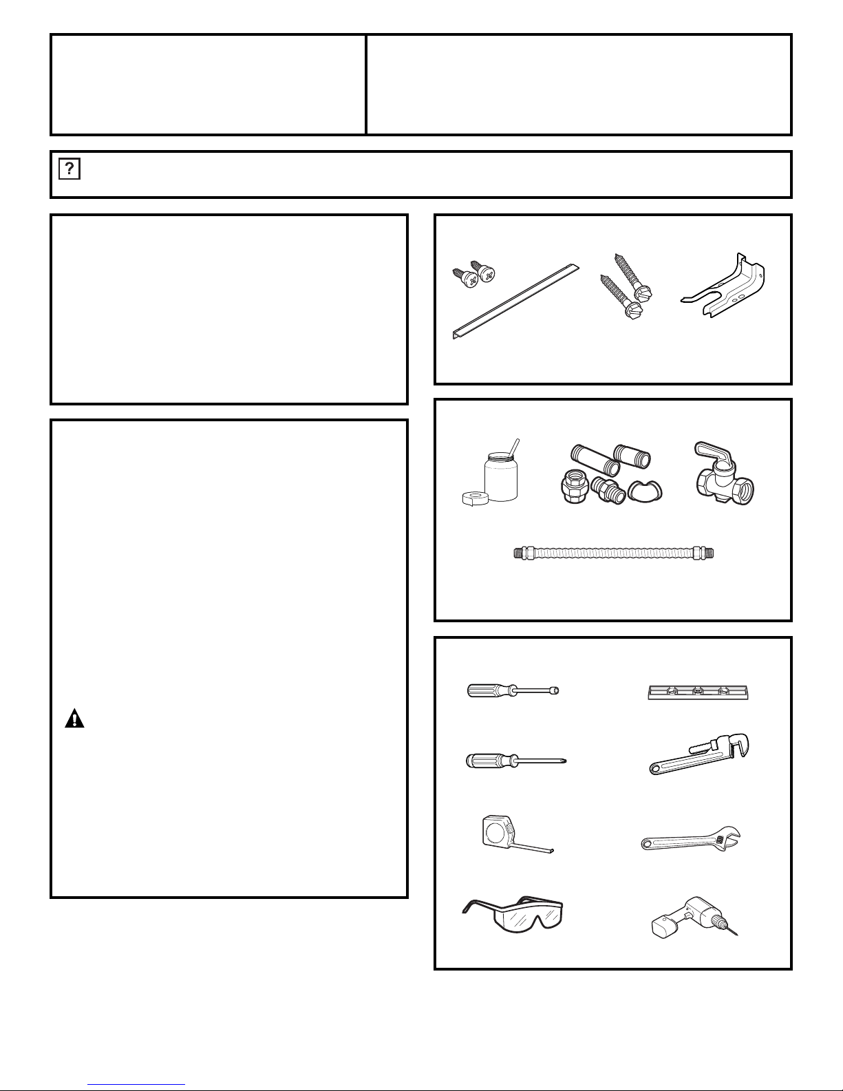
TOOLS YOU WILL NEED
MATERIALS YOU MAY NEED
1
31-10665 10-07 JR
Installation
Gas Slide-In Range
Instructions JGS905, JGS968, PGS968
BEFORE YOU BEGIN
Read these instructions completely
and carefully.
•
IMPORTANT — Save these
instructions for local inspector’s use.
•
IMPORTANT — Observe all
governing codes and ordinances.
• Note to Installer – Be sure to leave these
instructions with the Consumer.
• Note to Consumer – Keep these
instructions for future reference.
• Product failure due to improper installation
is not covered under the Warranty.
WARNING — This appliance must
be properly grounded.
•
IMPORTANT — Leak testing of the
appliance shall be conducted according to
the manufacturer’s instructions.
• Proper installation is the responsibility
of the installer and product failure due to
improper installation is NOT covered under
warranty.
IN THE COMMONWEALTH OF
MASSACHUSETTS:
• This product must be installed by a
licensed plumber or gas fitter.
• When using ball-type gas shut-off valves,
they shall be the T-handle type.
• A flexible gas connector, when used, must
not exceed 3 feet.
PARTS INCLUDED
Anti-Tip Bracket
Shut Off Valve
Pipe Fittings
CSA-Approved Flexible Gas Line
3/8″ Min. ID, 1/2″ NPT Connection,
3-foot Maximum Length (Massachusetts Only)
Joint Sealant
Wrench or Pliers
(for 1-7/16” Nut)
Level
1/4” Nut Driver
Safety Glasses Drill
Tape Measure
Screws
Rear Filler
2 Screws
Phillips Head
Screwdriver
Pipe Wrench
Questions? Call 800.GE.CARES (800.432.2737) or Visit our Website at: ge.com
In Canada, call 1.800.361.3400 or Visit our Website at: www.geappliances.ca
Page 2
FOR YOUR SAFETY:
WARNING — If the information in
this manual is not followed exactly, a fire,
explosion or gas leak may result causing
property damage, personal injury or death.
Do not store or use gasoline or other
flammable vapors and liquids in the vicinity
of this or any other appliance!
WHAT TO DO IF YOU
SMELL GAS:
• Do not try to light any appliance. Do not
touch any electrical switch; do not use any
phone in your building.
• Immediately call your gas supplier from a
neighbor’s phone. Follow the gas supplier’s
instructions.
• If you cannot reach your gas supplier, call
the fire department.
Installation and service must be performed by
a qualified installer, service agency or the gas
supplier.
2
Installation Instructions
IMPORTANT SAFETY INSTRUCTIONS
This range has been design certified by
UNDERWRITERS LABORATORIES for use in
the United States and Canada. You’ll find
safety precautions in your Owner’s Manual.
Read them carefully.
• Installation of this range must conform with
local codes or in the absence of local codes
with the National Fuel Gas Code, ANSI
Z223.1–Latest edition.
• Be sure your range is installed properly by
a qualified installer or service technician.
• To eliminate reaching over surface burners,
cabinet storage above burner should be
avoided.
• Do not install the unit near an outside door
or where a draft may affect its use.
Page 3
3
Installation Instructions
ANTI-TIP DEVICE
WARNING — To reduce the risk
of tipping, the appliance must be secured by
properly installed Anti-Tip bracket packed
with this appliance.
To check if the bracket is installed and
engaged properly, carefully tip the range
forward. The anti-tip bracket should engage
and prevent the range from tipping over.
WARNING —
• All ranges can tip
• Injury to persons could result
• Install Anti-Tip bracket packed
with range
• See Installation Instructions
If you pull the range out and away from the
wall for any reason, make sure the Anti-Tip
bracket is engaged when the range is pushed
back against the wall.
ELECTRICAL REQUIREMENTS
This appliance must be supplied with the
proper voltage and frequency and connected
to an individual, properly grounded branch
circuit, protected by a circuit breaker or fuse
having amperage as noted on the rating
plate. (Rating plate is located above the
storage drawer below the oven frame.)
We recommend you have the electrical wiring
and hookup of your range connected by a
qualified electrician. After installation, have
the electrician show you where your main
range disconnect is located.
Check with your local utilities for electrical
codes which apply in your area. Failure to
wire your range according to governing
codes could result in a hazardous condition.
If there are no codes, your range must be
wired and fused to meet the requirements of
the National Electrical Code, ANSI/NFPA No.
70–Latest edition. You can get a copy by
writing:
National Fire Protection Association
Batterymarch Park
Quincy, MA 02269
In Canada your range must be wired
and fused to meet the requirements of the
Canadian Electrical Code.
Be sure the installation of this product
in a mobile home conforms with the
Manufactured Home Construction and
Safety Standard, Title 24 CFR, Part 3280.
If this standard does not apply, you must
follow the standard for Manufactured Home
Installations, ANSI A225.1 and Manufactured
Home Installations, Sites and Communities
and ANSI/NFPA 501A or with local codes.
You can get a copy of the Federal Standard
by Writing:
Office of Mobile Home Standards
HUD Building
451 7th Street, S.W.
Washington, D.C. 24010
Rating
plate location
Page 4
INSPECT INSTALLATION
LOCATION
Refer to alternate construction section for
the following non-standard installations.
Counter opening extends to the wall:
Maintop Filler (supplied with the
range.) (See page 15 for Installation
Instructions) or
Backguard (Kit JXS36XX or JXS39SS).
Counter height greater than 36-3/4″:
Lower Trim Slide-In (Kit JXS56XX).
One side is not enclosed by a cabinet:
Bodyside (Kit JXS76XX).
Island Installation:
To provide an optimum installation, the
top surface of the countertop must be
level and flat (lie on the same plane)
around the 3 sides that are adjacent to
range cooktop. Proper adjustments to
make the top flat should be made or
gaps between the countertop and
range cooktop may occur. Forcing the
cooktop to fit may cause excessive
gaps and could break the glass and
void the warranty.
To obtain Kits:
a. Visit GE Web Site (See page 1)
b. Call GE Answer Center (See page 1)
c. Contact Dealer
D
C
B
A
1
4
Installation Instructions
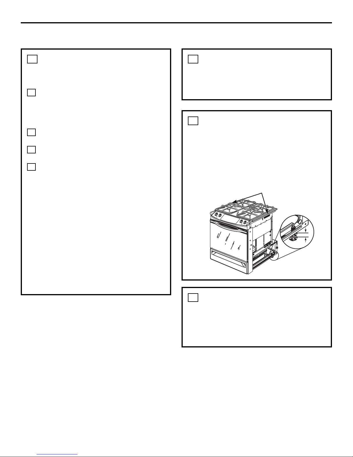
PRE-INSTALLATION CHECKLIST
MOVE RANGE INDOORS IN
FRONT OF CABINET OPENING
Do not use hand trucks when moving the
unpackaged range. Cooktop glass may be
broken.
2
PROTECT THE KITCHEN
FLOOR
Flatten and place a piece of the shipping
carton in front of the installation location to
protect the flooring.
NOTE: Do not remove the protective
channel from the sides of the glass cooktop,
if applicable, until later in the installation.
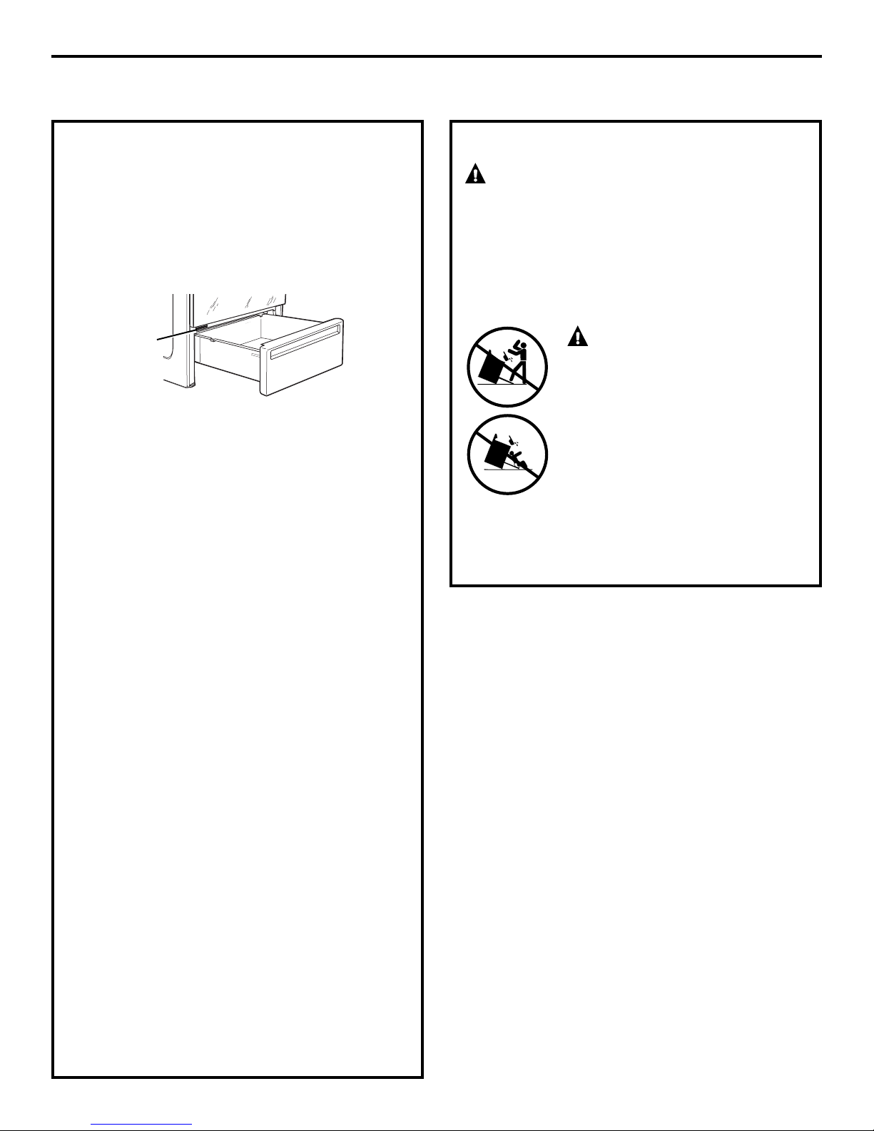
3
CAREFULLY, TILT RANGE TO
ACCESS RANGE LEVELING
LEGS
Use an adjustable wrench to screw leveling
legs out so that glass support flanges clear
top of countertop.
4
Protective
Channel
ADJUST
Page 5
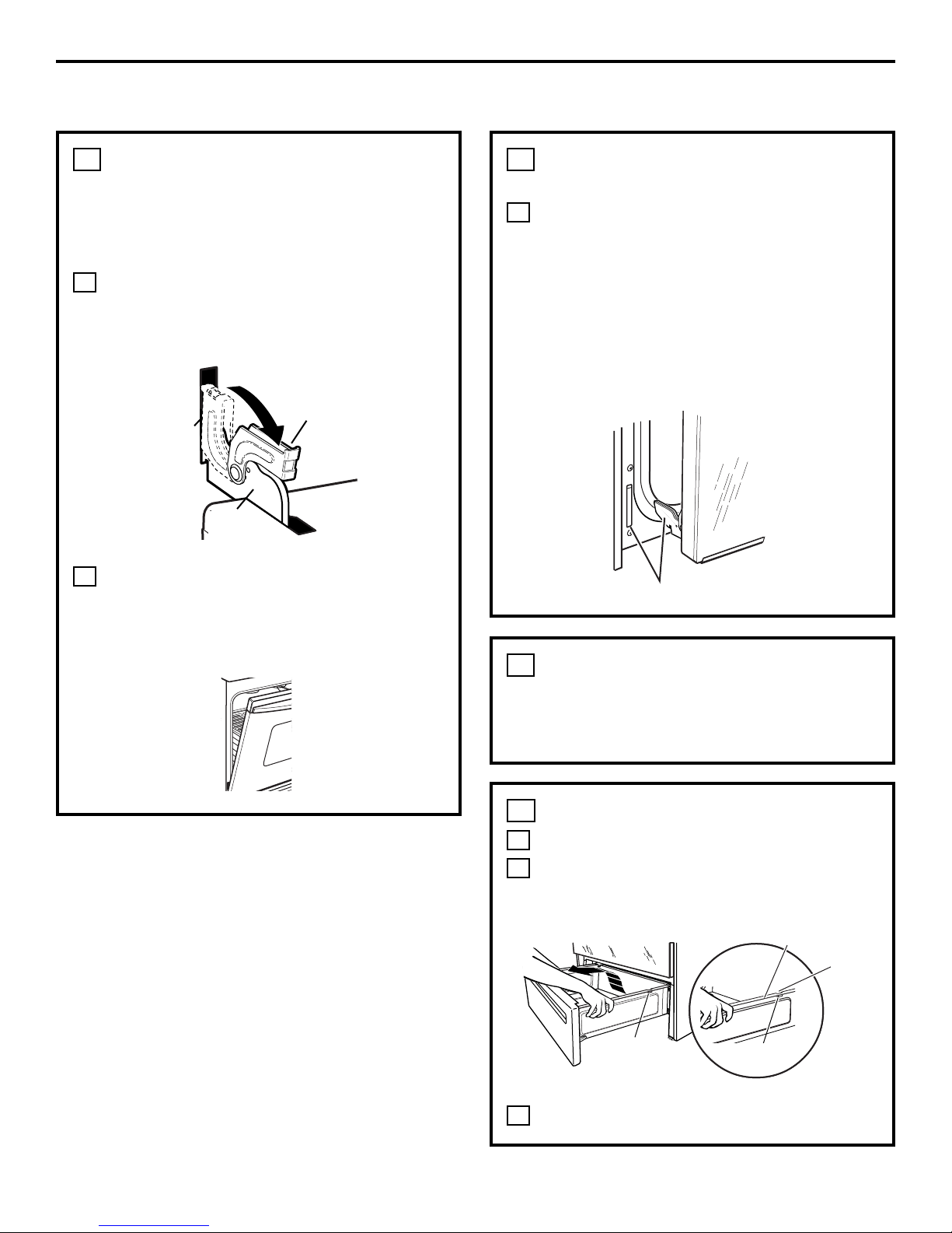
REMOVE THE DOOR IF
NECESSARY
Door removal is not a requirement for
installation of the product, but is an added
convenience. To remove the door:
UNLOCK HINGES
Push both hinge locks down toward the
door frame, to the unlocked position. This
may require a flat blade screwdriver.
POSITION DOOR
Place hands on both sides of the door, and
close the oven door to the removal position.
This is half way between the broil stop and
fully closed.
B
A
5
5
Installation Instructions
Hinge
slot
Hinge
unlocked
position
Hinge
arm
REMOVE THE DOOR IF
NECESSARY
(cont.)
LIFT OFF DOOR
Lift door up and out until the hinge arms
clear the slots.
DO NOT LIFT THE DOOR BY THE HANDLE.
NOTE: The oven door is very heavy. Be sure
you have a firm grip before lifting the oven
door off the hinges. Use caution once the
door is removed. Do not lay the door on its
handle. This could cause dents or scratches.
C
5
Hinge clears slot
REMOVE PACKING
MATERIALS
Also remove labels on door, plastic on trim
and panel and all tape around the range.
6
REMOVE STORAGE DRAWER
Pull the drawer out until it stops.
Lift the front of the drawer until the
stops clear the guides.
Pull forward and remove the drawer.
C
B
A
7
Rail
Guide
Stop
Stop
Page 6
6
Installation Instructions
PRE-INSTALLATION CHECKLIST (CONT.)
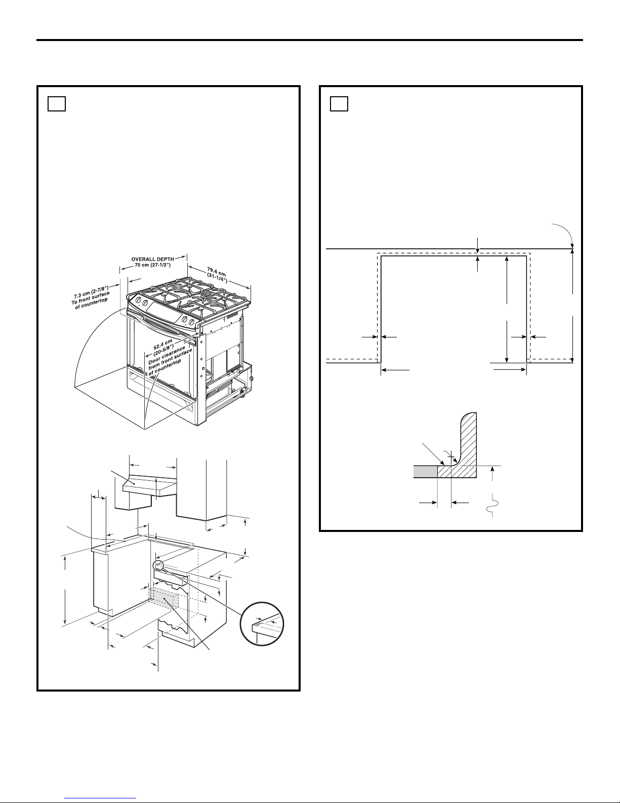
PRE-INSTALLATION CUTOUT
AND REQUIRED CLEARANCES
If cabinets are placed less than 30″ above the
range, see Alternate Construction, Step 19E,
on page 16.
NOTE: Product meets UL requirements for
0″ clearance to back and side walls.
Wall coverings, counters and cabinets around
range must withstand heat (up to 194°F)
generated by the range.
8
29-15/16"Min.
30-1/16" Max.
STANDARD INSTALLATION
If the construction of your cabinet cannot
provide a 1/4″ flat area at the back of the
countertop opening, consider changing the
countertop to accommodate this dimension.
See Alternate Construction section. If the area
is not flat, excess tension may be applied to
the glass cooktop, causing breakage and
voiding the warranty.
9
1/4″ min.
flat
9/16″
min.
flat
29-15/16″–30-1/16″
smooth cut
23-3/16″
25″
typically
Wall
Flat area
R
1/4″
9/16″
min.
flat
36″
Follow instructions
packaged with
alternate appliance
From Walls
For Optimum
Installation These
Surfaces Must
Be Flat & Level
″
to 36-1/2
″
35-3/4
from floor to
countertop
3
6
″
Min.
″
30″ Min.
″
23-3/16
Max. depth of
cord, plug,
receptacle box
& gas hookup
to prevent
″
3.5
interference
with drawer
15
″
12
″
29-15/16
30-1/16
″
Min.
″
Max.
30
″
Min.
from
cooking
surface to bottom
of overhead
cabinets
Drawer
″
13
Max.
depth
Countertop
Depth 25
7
″
Acceptable
Gas Line &
Electrical
Outlet Area
18
″
Min. vertical
distance from the
bottom of the adjacent
overhead cabinets
″
(typical)
1-1/4
″
Min. Counter top
to top of drawer
9/16
″
Shave Raised Edge
To
Clear 31-1/8
Wide Control Panel
″
Page 7
7
Installation Instructions
ELECTRICAL CONNECTIONS
INSTALLATION—ELECTRICAL
CONNECTIONS
Because of potential safety hazards
under certain conditions, we strongly
recommend against the use of an
extension cord. However, if you still
elect to use an extension cord, it is
absolutely necessary that it is a UL
listed 3-wire grounding-type appliance
extension cord and that the current
carrying rating of the cord in amperes
is equivalent to or greater than the
branch circuit rating. Such extension
cords are obtainable through your local
appliance dealer.
IMPORTANT: (Please read carefully)
FOR PERSONAL SAFETY, THIS
APPLIANCE MUST BE PROPERLY
GROUNDED.
An adequate electrical supply and
outlet must be used to operate the
electrical parts of your range.
• The power cord of this appliance is
equipped with a three-prong (grounding)
plug which must be used with a properly
grounded three-hole outlet with standard
120 Volt, 60 cycle AC household current.
• When a standard two-prong wall
receptacle is encountered, it is the
personal responsibility and obligation
of the customer to have it replaced with
a properly grounded three-prong wall
receptacle by a qualified electrician.
Do not under any circumstances cut or
remove grounding prong from the range
cord. Failure to provide proper ground may
create a hazardous condition.
B
A
10
Page 8
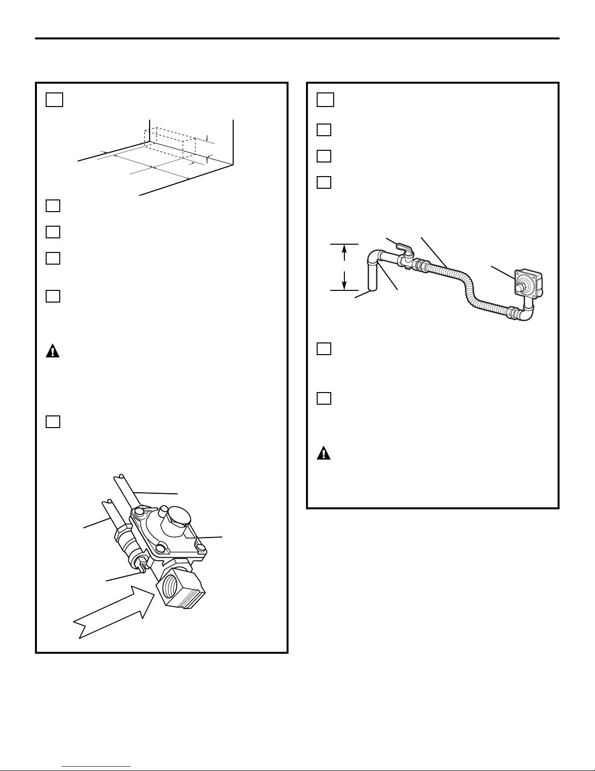
MAKING THE CONNECTIONS
(cont.)
Install 1/2″ flare union adaptor to the
1/2″ NPT elbow on pressure regulator.
Connect flexible appliance connector to
flare union.
Move range into approximate position
and connect flexible connector to gas
supply line with proper flare union
adaptor.
To prevent gas leaks, put a pipe joint
sealant or Teflon
®
tape on all male
threads. NOTE: Make sure sealant or tape
is compatible with Natural and LP gases.
When you are finished making
connections, be sure that all range knobs
are turned to OFF before you open the
main gas supply valve.
WARNING: Do not use a flame
to check for gas leaks. Use liquid leak detector
at all joints and connections to check for leaks
in the system.
J
I
H
G
F
11
8
Installation Instructions
GAS CONNECTIONS
MAKING THE CONNECTIONS
Install a manual shut-off valve in the gas
supply line in an easily accessible location.
Know how and where to shut off the gas
supply to the range.
Shut off gas supply before removing an
old range. Leave it off until hookup of
new range is finished.
Because solid pipe restricts moving the
range, we recommend use of a C.S.A.
certified flexible metal appliance
connector.
WARNING: Never reuse old
flexible connectors. The use of old flexible
connectors can cause gas leaks and personal
injury. Always use new flexible connectors
when installing a gas appliance.
Before making gas connections, make
sure that the oven shut-off lever (visible at
the back of range) is in the open position.
E
D
C
B
A
11
3″
15″
12″
3
1
⁄2″
7″
Gas supply to
top burner
Pressure
regulator as
seen from
front of range
Gas
supply
to oven
Oven shut-off
lever shown in
the open position
Pressure
regulator
Gas
supply
line
90° street
elbow
Shut-off valve Flexible gas line
7″ Max.
Gas Inlet
Page 9
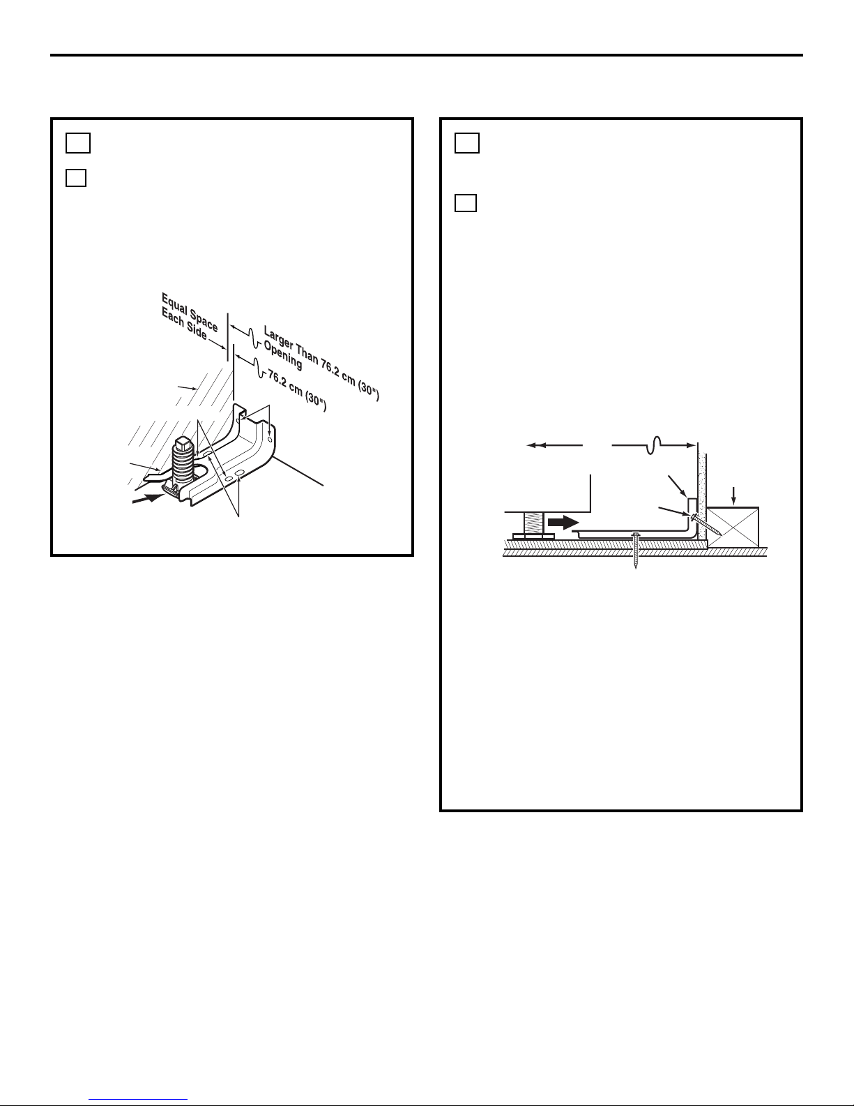
INSTALL THE ANTI-TIP BRACKET
LOCATE THE BRACKET
a. Decide whether the bracket will be
installed on the right or left side of the
range opening.
b.Place the bracket as shown in Fig. 1.
A
12
Rear
leveling leg
Wall
FLOOR-CONCRETE
9
Installation Instructions
INSTALL THE RANGE
INSTALL THE ANTI-TIP BRACKET
(cont.)
INSTALL THE BRACKET IN WOOD
OR CONCRETE
INSTALLATION—WOOD CONSTRUCTIONS
a. Locate the centers of the 4 holes identified
in Fig. 1 as Floor–Wood and Wall.
b. Drill a 1/8″ pilot hole through the
pre-marked areas. Note the angle of the
wall screw in Fig. 2.
c. Mount the Anti-Tip bracket with the
4 screws provided.
INSTALLATION—CONCRETE CONSTRUCTIONS
a. For concrete installation, you will need
two 1/4″ x 1-1/2″ lag screws and two sleeve
anchors.
b. Locate the center of the 4 holes identified
in Fig. 1 as Floor–Concrete and Wall.
Drill the recommended size holes in each.
c. Install the sleeve anchors into the
predrilled concrete holes and install the
lag and wall screws through the Anti-Tip
bracket. Make sure the screws are securely
tightened.
B
12
FLOOR-WOOD
Bracket
side
Adjacent
cabinet
Top front
edge of
countertop
25″
Wall plate
Screw
must enter
wood or
metal
Bracket
Fig. 1
Fig. 2
Page 10
SLIDE RANGE INTO OPENING
Position the range in front of the cabinet
opening.
Make sure that the glass which overhangs
the countertop clears the countertop.
If necessary, raise the unit by lowering
the leveling legs.
Push while lifting the range into the
opening, until the range is within 2″
of engaging the anti-tip bracket.
Remove the protective trim from the side
of glass (if provided).
Using the adjustable pliers or wrench,
carefully screw in the back leveling leg
until the glass overhang comes to rest
on the countertop.
Carefully screw in the front two leveling
legs (similar to Step E) until the glass
overhang touches the countertop.
Carefully push the range into the opening
until the countertop fully engages the
control panel. The back glass overhang
should cover the cutout opening.
G
F
E
D
C
B
A
13
10
Installation Instructions
INSTALL THE RANGE (CONT.)
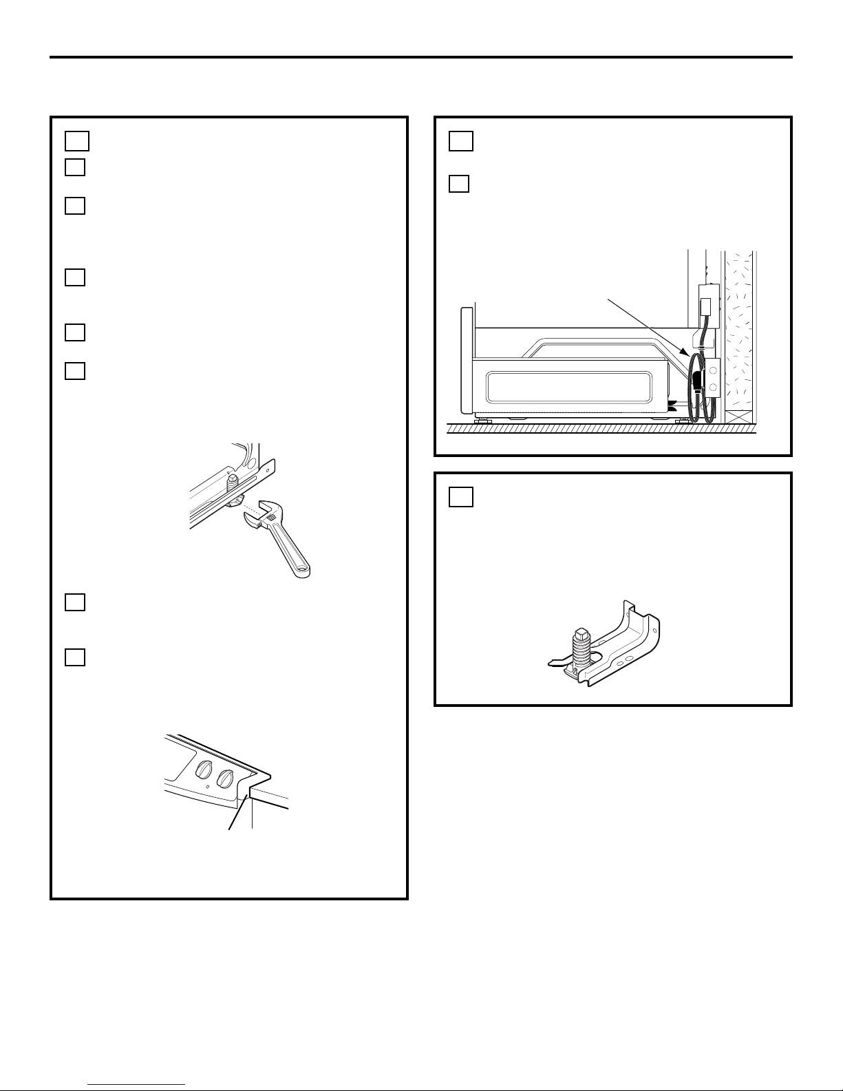
SLIDE RANGE INTO OPENING
(cont.)
Plug the range cord into the receptacle.
Locate the cord in the back of the range
in a manner that it will not touch or be
moved by the drawer.
H
13
STORAGE DRAWER
Position range cord
so that there is no
interference with
storage drawer
Adjustable
wrench or pliers
Countertop
Make sure the edge of
the countertop fits flush
against the end of the
front control panel
FINAL CHECK OF ANTI-TIP
BRACKET
When installation is complete and the range is
in place, check to be sure that the rear leveling
leg is fully inserted into the slot of the Anti-Tip
Bracket.
14
Page 11

REPLACE THE OVEN DOOR
NOTE: The oven door is heavy. You may need
help lifting the door high enough to slide it
into the hinge slots. Do not lift the door by
the handle.
Lift the oven door by placing one hand on
each side. The door is heavy, so you may
need help. Do not lift the door by the
handle.
With the door at the same angle as the
removal position (halfway between the
closed and broil stop position), seat the
notch of the hinge arm into the bottom
edge of the hinge slot. The notch of the
hinge arm must be fully seated into the
bottom of the slot.
Open the oven door as far as it will open.
Push the hinge locks up against the front
frame of the oven cavity, to the locked
position.
Close the oven door.
E
D
C
B
A
15
11
Installation Instructions
REPLACE THE STORAGE
DRAWER
Place the drawer rail on the guides.
Push the drawer in until it stops.
Lift the front of the drawer and push in
until the stops clear the guides.
Lower the front of the drawer and push in
until it closes.
SPECIAL INSTRUCTIONS IF YOU ARE
HAVING PROBLEMS WHILE REPLACING
THE STORAGE DRAWER
Remove and replace, making sure the power
cord is not obstructing the drawer and/or the
rail is in the guide.
Remove and replace, making sure the rail is in
the guide.
D
C
B
A
16
Stop
Bottom edge
of slot
Hinge in
locked position
Notch of hinge
securely fitted
into bottom of
hinge slot
Drawer does
not close
completely
Drawer
front panel
tipped away
from body
side
Rear drawer
support is on top
of guide rail on
the high side
Drawer front panel
tipped to one side
Hinge arm
Hinge notch
If Drawer Won’t Close:
If Drawer is Crooked:
Power cord
may be
obstructing
drawer in
this area
Rear drawer
support is
resting on top
of guide rail
Page 12

12
Installation Instructions
INSTALL THE RANGE (CONT.)
COOKTOP BURNERS
ASSEMBLING THE BURNERS
CAUTION: The electrode of the
spark igniter is exposed. Be careful not to
snag the electrode of the spark igniter with
a cleaning cloth. Damage to the igniter could
occur. Be careful not to turn on any cooktop
controls while cleaning. A slight electrical
shock might result, which could cause you
to knock over hot cookware.
FOR GLASS CERAMIC COOKTOPS
a. Place the burner head on the burner base,
so that the pins match up with the slots on
the base.
b.Position the burner cap on the burner head.
c. Place the burner grate over the burner
assembly. The grates fit over the raised
area on the burner head.
A
17
CHECK FOR LEAKS
Turn the gas supply on and use a liquid leak
detector (soap solution) at all joints and
connections to check for leaks. Do not use an
open flame to look for leaks. Be sure all leaks
are stopped before lighting burners.
B
PRESSURE TEST INFORMATION
The maximum allowable supply pressure
for the regulator is 14″ W.C. The minimum
supply pressure needed to check the regulator
setting is 7″ W.C. for natural gas and 10″ W.C.
for LP gas.
WARNING: The range and its
individual shut-off valve must be disconnected
from the gas supply piping system during any
pressure testing of the gas supply system at
test pressures of more than 1/2 psig (pounds
per square inch gauge). The range must be
isolated from the gas supply piping system
by closing its individual shut-off valve during
any pressure testing of the gas supply system
at test pressures equal to or greater than
1/2 psig. NOTE: 1/2 psig = 13.855″ w.c.
C
Spark
igniter
location
Burner
grate
Burner
base
Burner
cap
Burner
head
Spark
igniter
Glass
maintop
Vent
cover
Page 13

13
Installation Instructions
CHECK THE IGNITERS
Operation of the electric igniters should be
checked after the cooktop and supply line
have been carefully checked for leaks and the
cooktop has been connected to the electrical
power.
a. Turn on gas.
b. Push and turn a burner valve to the LITE
position.
• The burner valve should light when gas
is available to the burner.
• Once the burner lights, it should be
turned out of the LITE position.
c. Try each valve separately until all burners
have been checked.
D
BURNER IGNITION
Cooktop Spark Ignition – When you turn
the cooktop knob to LITE, the spark igniter
makes a series of electric sparks (ticking
sounds) which light the burner. During a
power failure the burners will not light
automatically. In an emergency, a cooktop
burner may be lit with a match by following
the steps below.
WARNING: Lighting gas burners
with a match is dangerous. You should match
light the cooktop burners only in an
emergency.
a. Light a match and hold the flame near the
burner you want to light. Wooden matches
work best.
b. Push in and turn the control knob slowly.
Be sure you are turning the correct knob
for the burner you are lighting.
NOTE: If the burner does not light within
five seconds, turn the knob off and wait five
minutes before trying again.
E
BURNER FLAMES
Turn each burner on. Turn each burner knob
to the high position. Flames should be blue
in color with no or little trace of yellow. The
burner flames should not flutter or blow away
from the burner. The inner cone of the flame
should be between 1/2″ to 3/4″ long. If the
burner flames are yellow in color or not the
proper length, call GE Service.
Burners should be checked frequently.
WARNING: If you attempt to
measure the inner cone of the flame, please
use caution. Burns could result.
F
1/2″ to 3/4″
COOKTOP
BURNER
Flames should circle burner
Page 14

14
Installation Instructions
INSTALL THE RANGE (CONT.)
BAKE AND BROIL BURNERS
If the bake and/or broil burners have lifting or
“lazy” (floating) flames or you have a yellow
flame, perform the following procedures:
CHECKING THE OVEN BURNERS
To check the bake burner flames with the
oven door in the closed position:
1. Open the door and remove it.
2. Remove the oven racks.
3. Remove the oven bottom.
Lift the oven bottom up at rear and pull
forward.
4. Remove the four screws holding the burner
baffle (flame spreader) to the burner box.
5. Install and close the oven door.
6. Turn on the bake burner.
As you watch the flames, check the
following:
• Burner flames should not flutter or blow
away from the burner.
• They should be blue in color with no trace
of yellow.
The broil burner flames may be seen without
removing the racks, oven bottom or bake
baffles.
A
18
ADJUST THE AIR SHUTTER
BAKE BURNER
1. Remove the orifice fitting cover.
2. Use a screwdriver to loosen the air shutter
screw.
3. Adjust the air shutter to 11/32″.
4. Retighten the air shutter screw.
WHAT ADJUSTMENT TO MAKE:
a. If the flames are yellow, open the air
shutter more than the original setting.
b. If the flames blow away or fluttered from
the burner, close the air shutter more than
the original setting.
Burners should be checked frequently.
BROIL BURNER
1. The broil burner is located and accessible
in the top rear of the oven.
2. Using a
screwdriver,
loosen the air
shutter
adjustment screw.
3. Make the air
shutter
adjustment.
4. Retighten the air
shutter screw.
5. Check the inner
cone of the flame.
It should be
between 1/2″ and
3/4″ long for the
oven bake and
broil burners.
WHEN ALL ADJUSTMENTS ARE MADE AND
THE RESULTS ARE SATISFACTORY
1. Replace the orifice fitting cover.
2. Replace the burner baffle (flame spreader)
and screws.
3. Replace the oven bottom.
4. Replace the oven door.
B
w
R
R
Inner cone of
flame
Oven broiler
burner
1/2″ to 3/4″
Air shutter
adjustment screw
Dim. “A”
Orifice fitting
cover
Air shutter
Air shutter
screw
Dim. “A”
Air Shutter
Adjustment Scre
1/2" TO 3/4"
CONO INTERIOR
DE LLAMA
QUEMADOR PA
HORNEAR/ASA
Page 15

15
Installation Instructions
ALTERNATE CONSTRUCTION
PREPARATION
OPTIONAL MAINTOP FILLER OR
BACKGUARD KIT
If counter opening extends to the wall, it will
require Maintop Filler Kit (supplied with the
range) or Backguard Kit (JXS36XX or
JXS39SS) to close the gap.
NOTE: If the countertop is greater than 25″,
it will show a gap between the backguard
and wall or between filler kit and the wall.
If the countertop is less than 25″, a gap will
occur between the countertop front and the
control panel ends (see Step 13G).
If you are using the optional backguard kit,
refer to the backguard kit instructions for
installation details.
If you use the filler kit, place the metal filler
piece supplied with the range to the back of
the range as shown in the figure below.
Start the 2 screws into the upper holes at the
outside rear of the range above the louvers
and through the slots in the trim, holding
the filler piece centered on the maintop
frame and pushing upward to close the gap
between the bottom of the glass and the
filler trim.
A
19
When the trim is set in the proper position,
tighten the 2 mounting screws. The top of the
trim should be located below the top surface
of the glass to prevent pots, pans and skillets
from damaging the painted parts.
Refer to the Standard Installation of the
Range on page 6.
Wall
25″
Must be
level
Must be
flat
30″
smooth cut
Must be level
31-1/8″
Must
be
flat
(2) #8
screws
Maintop filler
Range
Cooktop
FOR NON-BUILT-IN INSTALLATION
(END OF CABINET LOCATION)
When installing the range at the end of
a cabinet section which will expose the
unfinished side of the range, use Body Side
Kit (JXS76XX). Refer to the kit instructions
for installation details.
B
ISLAND INSTALLATION
Attach the Anti-Tip bracket per instructions
in Step 12, making sure that the rear of
the bracket is 25″ from the front of the
countertop.
Be aware that the screws provided are long
and may penetrate through the back of the
island cabinets. In this event, use shorter
screws (not provided) or the screws provided
should be used in the floor (see Step 12B for
Wood/Concrete Floor Installation).
Do not use Backguard Kit JXS36XX or
JXS39SS.
C
Page 16

Installation Instructions
INSTALL THE RANGE (CONT.)
ALTERNATE CONSTRUCTION
PREPARATION (cont.)
FOR CABINET OPENINGS
APPROXIMATELY 30-3/8″
If range is installed in cabinet opening
approximately 30-3/8″, the Vertical Side Trim
Kit (JXS86XX) should be used to cover gaps
between range sides and cabinet. Refer to
the kit instructions for installation details.
D
19
CABINETS OVER THE RANGE LESS
THAN 30″
If a 30″ clearance between cooking surface
and overhead combustible material or metal
cabinets cannot be maintained, protect the
underside of the cabinets above the cooktop
with not less than 1/4″ insulating millboard
covered with sheet metal not less than
0.0122″ thick.
E
OPERATION CHECKLIST
• Double check to make sure everything in
this guide has been completed. Rechecking
steps will ensure safe use of the cooktop.
• Make sure all controls are left in the OFF
position.
• Make sure the flow of combustion and
ventilation air to the cooktop is unobstructed.
• The serial plate for your Range is located
under the oven door above the storage
area. In addition to the model and serial
numbers, it tells you the ratings of the
burners and the type of fuel and pressure
the cooktop was adjusted for when it left
the factory.
• When ordering parts, always include the
serial number and model number to ensure
proper replacement parts.
• Recheck Steps: Double check to make
sure everything in this guide has been
completed. Rechecking steps will ensure
safe use of the Range.
20
IN SOME CASES
With L.P. gas, some yellow tipping on the
outer cone is normal.
Foreign particles in the gas line may
cause an orange flame at first, but this
will soon disappear.
SPECIAL NOTE:
To convert the oven back to natural gas,
reverse the instructions given in making L.P.
Adjustments.
Once the conversion is complete
and checked ok, fill out the LP
sticker and include your name,
organization and the date the
conversion was made. Apply the sticker near
the regulator to alert others in the future that
this appliance has been converted to LP gas.
If converting back to natural gas from LP,
please remove the sticker so others know the
appliance is set to use natural gas.
B
A
Please see L.P. conversion instructions
supplied with this range when L.P. Gas
is used.
NOTE: Instructions are mounted on
regulator bracket.
ADJUSTING LOW FLAME SETTING
ON COOKTOP BURNERS
Low setting adjustments must be made with
two other burners in operation on a medium
setting. This procedure prevents the low
flame from being set too low, resulting in the
flame being extinguished when other burners
are turned on.
Remove the valve control knobs.
Through the opening, locate the valve
bypass screw located on the lower right
side of the valves.
Using a small screwdriver, screw down
the bypass screw fully in a clockwise
rotation.
C
B
A
16
Printed in the United States
Page 17

OUTILS DONT VOUS AUREZ BESOIN
MATÉRIAUX DONT VOUS POUVEZ
AVOIR BESOIN
1
31-10665 10-07 JR
Si vous avez des questions, appelez le 1.800.361.3400 ou visitez notre site Web à l’adresse :
www.electromenagersge.ca
Instructions Cuisinière encastrée
d’installation
au gaz
JGS905, JGS968, PGS968
AVANT DE COMMENCER
Lisez ces instructions complètement et avec
soin.
•
IMPORTANT — Conservez ces
instructions pour l’inspecteur local.
•
IMPORTANT — Respectez tous les
codes et les ordonnances en vigueur.
• Note à l’installateur : Assurez-vous de
donner toutes ces instructions au
consommateur.
• Note au consommateur : Conservez ces
instructions pour référence future.
• La garantie ne couvre aucune panne due à
une mauvaise installation.
AVERTISSEMENT — Cet
appareil ménager doit être bien mis à la terre.
•
IMPORTANT — Vous devez faire
les essais de fuite de cet appareil en vous
conformant aux instructions du fabriquant.
• L’installateur est responsable d’une bonne
installation et la garantie ne couvre aucune
panne due à une mauvaise installation.
PIÈCES COMPRISES
Soutien antibasculement
Robinet d’arrêt
Raccords de tuyaux
Raccord flexible de gaz approuvé par l’ACNOR
DI min 3/8’’, Jonction NPT 1/2’’
Produit d’obturation
des joints
Clé ou tenailles (pour
un écrou de 1-7/16”)
Niveau
Tourne-écrou de 1/4”
Lunettes de sécurité Perceuse
Mètre
Vis
Entretoise arrière
2 vis
Tournevis à tête
Phillips
Clé à tube
Page 18

VOTRE SÉCURITÉ :
AVERTISSEMENT —
Si vous ne suivez pas exactement les
renseignements contenus dans ce manuel,
vous pouvez occasionner un incendie, une
explosion ou une fuite de gaz qui peut causer
des dommages matériels, des blessures
corporelles ou la mort.
Ne conservez ou n’usez jamais d’essence
ou d’autre liquide ou vapeur inflammable à
proximité de cet appareil ou de tout autre
appareil ménager.
QUE FAIRE SI VOUS
SENTEZ LE GAZ :
• N’essayez jamais d’allumer un appareil
ménager. Ne touchez aucun commutateur
électrique; n’utilisez aucun téléphone dans
votre bâtiment.
• Appelez immédiatement votre fournisseur
de gaz en utilisant le téléphone d’un voisin.
Suivez les instructions du fournisseur de
gaz.
• Si vous n’arrivez pas à communiquer avec
votre fournisseur de gaz, appelez les
pompiers.
L’installation et le service doivent être faits
par un installateur qualifié, une agence de
service ou votre fournisseur de gaz.
2
Instructions d’installation
CONSEILS DE SÉCURITÉ IMPORTANTS
La conception de cette cuisinière a
été certifiée par les UNDERWRITERS
LABORATORIES du Canada. Vous trouverez
des précautions de sécurité dans votre
Manuel du propriétaire. Lisez-les avec soin.
• L’installation de cette cuisinière doit
se conformer aux codes locaux ou, en
l’absence de codes locaux, au National Fuel
Gas Code, ANSI Z223.1 – Dernière édition.
• Assurez-vous que votre cuisinière soit bien
installée par un installateur qualifié ou un
technicien du service.
• Pour éviter de vous pencher sur les
brûleurs de surface, vous devez éviter de
placer au-dessus des brûleurs une armoire
de rangement.
• N’installez jamais votre appareil près d’une
porte donnant sur l’extérieur ou dans tout
endroit où un courant d’air peut gêner son
usage.
Page 19

3
Instructions d’installation
MÉCANISME ANTI-BASCULANT
AVERTISSEMENT — Pour réduire
le risque de basculement, vous devez fixer votre
appareil en installant bien le support antibasculement livré avec votre appareil.
Pour vérifier si ce support est bien installé
et engagé, faites doucement basculer la cuisinière
vers l’avant. Le support anti-basculement doit
s’engager et empêcher la cuisinière de basculer.
AVERTISSEMENT —
• Toutes les cuisinières peuvent
basculer
• Cela peut occasionner des
blessures corporelles
• Installez le support anti-basculant
livré avec votre cuisinière
• Consultez les instructions
d’installation
Si vous tirez la cuisinière pour l’écarter du mur
pour quelque raison que ce soit, assurez-vous que
le support anti-basculement s’engage quand vous
repoussez la cuisinière contre le mur.
EXIGENCES ÉLECTRIQUES
Cet appareil ménager doit être livré avec le
bon voltage et la bonne fréquence et branché
à son propre circuit de dérivation bien mis à
la terre, protégé par un disjoncteur ou un
fusible qui ont l’ampérage noté sur la plaque
signalétique (la plaque signalétique est située
au dessus du tiroir de rangement sous le
châssis de la cuisinière).
Nous vous recommandons de faire brancher
le câblage électrique et la fiche de votre
cuisinière par un électricien qualifié. Après
l’installation, demandez à l’électricien de vous
montrer l’emplacement de votre coupe-circuit
principal.
Demandez à votre entreprise de services
publics les codes électriques en vigueur
dans votre région. En ne câblant pas votre
cuisinière conformément aux codes en
vigueur, vous provoquez une situation
dangereuse. En l’absence de codes, vous
devez câbler et isoler votre cuisinière
conformément aux exigences du Canadian
Electrical Code.
Emplacement
de la plaque
signalétique
Page 20

INSPECTEZ L’EMPLACEMENT
OÙ VOUS ALLEZ INSTALLER
Consultez la section d’autre construction
pour les installations suivantes qui ne sont
pas normales.
L’ouverture du comptoir se poursuit
jusqu’au mur :
Entretoise arrière (fournie avec la
cuisinière (consultez les installations
d’instruction à la page 15) ou
Dosseret (trousse JXS36XX ou
JXS39SS).
La hauteur du compteur est plus
grande que 93,4 cm (36-3/4″):
Garniture du bas à glisser (trousse
JXS56XX).
Un côté n’est pas enfermé dans une
armoire :
Côté d’appareil (trousse JXS76XX).
Installation dans un îlot :
Pour obtenir une bonne installation, la
surface du haut du comptoir doit être
horizontale et plate (au même niveau)
des trois côtés qui sont adjacents à la
table de cuisson de la cuisinière. Vous
devez bien ajuster la surface du haut
afin de bien l’aplatir, autrement il se
produira des écarts entre le comptoir et
la table de cuisson de votre cuisinière.
En poussant la table de cuisson pour
aller dans le comptoir, vous pouvez
occasionner des écarts excessifs et
vous pouvez casser la vitre et annuler
la garantie.
Pour obtenir les trousses :
a. Visitez le site Web GE (voir page 1)
b. Appelez le centre de réponse GE
(voir page 1)
c. Appelez le vendeur
D
C
B
A
1
4
Instructions d’installation
LISTE DE VÉRIFICATION AVANT L’INSTALLATION
AMENEZ LA CUISINIÈRE À
L’INTÉRIEUR EN FACE DE
L’OUVERTURE DE L’ARMOIRE
N’utilisez pas de chariot à main pour
transporter la cuisinière sans emballage. La
vitre de la table de cuisson peut se casser.
2
PROTÉGEZ LE PLANCHER DE
LA CUISINE
Aplatissez et placez un morceau de carton
d’emballage devant l’emplacement où vous
allez installer votre cuisinière pour protéger
le plancher.
NOTE : Attendez plus tard au cours
de l’installation pour enlever les rails
protecteurs des côtés de la table de
cuisson en verre, le cas échéant.
3
FAITES BASCULER AVEC SOIN
LA CUISINIÈRE POUR AVOIR
ACCÈS AUX PIEDS
D’INCLINAISON DE LA
CUISINIÈRE
Utilisez une clé ajustable pour visser les
pieds d’inclinaison afin de mettre à niveau
le soutien de la vitre avec le haut du
comptoir.
4
Rail
protecteur
Ajustez
Page 21

5
Instructions d’installation
ENLEVEZ LA PORTE SI C’EST
NÉCESSAIRE
(suite)
ENLEVEZ LA PORTE EN LA
SOULEVANT
Enlevez la porte en la soulevant et en la
faisant sortir jusqu’à ce que les bras de
charnière sortent des fentes.
NE SOULEVEZ JAMAIS LA PORTE À UN
ANGLE.
NOTE : La porte de la cuisinière est
très lourde. Assurez-vous de bien la saisir
avant de la soulever pour l’enlever de ses
charnières. Faites bien attention une fois
que vous avez enlevé la porte. Ne posez
jamais la porte sur sa poignée. Cela peut
occasionner des rayures ou des bosses.
C
5
La charnière sort de sa fente
ENLEVEZ LA PORTE SI C’EST
NÉCESSAIRE
Il n’est pas indispensable d’enlever la porte
pour installer votre cuisinière, mais cela
peut vous faciliter la tâche. Pour enlever
la porte :
DÉVERROUILLEZ LES CHARNIÈRES
Poussez les deux verrous de charnières
vers le bas, vers le châssis de la porte, en
position déverrouillée. Cela peut nécessiter
un tournevis à tête plate.
METTEZ EN PLACE LA PORTE
Placez vos mains des deux côtés de la
porte et fermez la porte de la cuisinière en
position d’enlèvement. C’est à mi-chemin
entre l’arrêt de grillade et la fermeture
totale.
B
A
5
ENLEVEZ LES MATÉRIAUX
D’EMBALLAGE
Enlevez les étiquettes de la porte, la matière
plastique de la garniture et du panneau et
tout le ruban collé autour de la cuisinière.
6
ENLEVEZ LE TIROIR DE
RANGEMENT
Tirez le tiroir vers l’extérieur jusqu’à ce
qu’il s’arrête.
Soulevez l’avant du tiroir jusqu’à ce
que les arrêts sortent des guides.
Tirez vers l’avant et enlevez le tiroir.
C
B
A
7
Rail
Guide
Arrêt
Arrêt
Fente de
charnière
Position
déverrouillée
de charnière
Bras de
charnière
Page 22

6
Instructions d’installation
LISTE DE VÉRIFICATION AVANT L’INSTALLATION (SUITE)
DÉCOUPE AVANT L’INSTALLATION
ET DÉGAGEMENT REQUIS
Si les armoires sont placées à moins de
76,2 cm (30’’) au-dessus de la cuisinière,
consultez la section d’autre construction,
étape 19E, à la page 16.
NOTE : Votre appareil remplir les exigences
UL de 0’’ de dégagement aux murs arrière et
de côté.
Les revêtements de mur, les comptoirs et
les armoires autour de la cuisinière doivent
supporter la chaleur (pouvant atteindre 194°F)
produite par la cuisinière.
8
INSTALLATION NORMALE
Si la construction ou votre armoire ne peut
fournir une surface plate de 6 mm (1/4″) à
l’arrière de l’ouverture du comptoir, envisagez
changer le comptoir pour obtenir cette
dimension. Consultez la section d’autre
construction. Si la surface n’est pas plate,
vous risquez de mettre trop de pression sur
la table de cuisson en verre, et la casser en
annulant la garantie.
9
6 mm (1/4″)
Plat min.
76 cm à 76,4 cm
(29-15/16″–30-1/16″)
Coupe douce
58,9 cm (23-3/16″)
63,5 cm
(25″)
Typiquement
Mur
Surface plate
R
6 mm (1/4″)
14 mm
(9/16″)
Plat min.
91,4 cm (36″)
Profondeur
totale 70 cm
(27-1/2″)
7,3 cm (2-7/8″)
Depuis la
surface avant
du comptoir
52,4 cm (20-5/8″)
Espace libre pour
la porte, depuis la
surface avant du
comptoir
79,4 cm (31-1/4″)
15,2 cm (6″)
min depuis
les murs
Pour une bonne
installation, ces
surfaces doivent
être plates et
horizontales
8,9 cm (3,5″)
Profondeur
max. pour le
cordon, la
prise, la prise
électrique et le
raccordement
de gaz pour
éviter de gêner
le tiroir
Tiroir
33 cm (13″)
max de
profondeur
45,7 cm (18″)
min de
distance
verticale
depuis le bas
des armoires
supérieures
adjacentes
63,5 cm (25″) Profondeur de
comptoir (normal)
76,2 cm (30″) min
depuis la table de
cuisson jusqu’au
bas de l’armoire
supérieure
3,2 cm (1-1/4″)
min depuis le
comptoir jusqu’en
haut du tiroir
76,2 cm
(30″) min
Rabotez l’arête
saillante pour libérer
79,1 cm (31-1/8″)
d’épaisseur de
panneau de contrôle
38,1 cm (15″)
Endroit acceptable
pour la conduite de
gaz et la prise
électrique
58,9 cm
(23-3/16″)
17,8 cm
(7″)
7,6 cm (3″)
Suivez les instructions
emballées avec l’autre
appareil ménager
30,5 cm (12″)
90,8 cm
(35-3/4″) à 92,7
cm (36-1/2″)
depuis le
plancher
jusqu’au
comptoir
1,5 cm
(9/16″)
76 cm (29-15/16″) min
76,5 cm (30-1/16″) max
14 mm
(9/16″)
Plat min.
Page 23

7
Instructions d’installation
BRANCHEMENT ÉLECTRIQUE
INSTALLATION—
BRANCHEMENT ÉLECTRIQUE
À cause des risques de sécurité
dans certaines conditions, nous vous
recommandons fortement de ne pas
utiliser de rallonge. Cependant, si vous
décidez tout de même d’utiliser une
rallonge, il est absolument nécessaire
que cette rallonge soit une rallonge
pour appareil électroménager à trois
fils et mise à la terre, dont l’ampérage
soit égal ou supérieur à celui du circuit
de dérivation. Vous trouverez cette
rallonge chez votre revendeur local
d’appareils électroménagers.
IMPORTANT : (Veuillez lire
attentivement) POUR VOTRE SÉCURITÉ
PERSONNELLE, VOUS DEVEZ BIEN
METTRE À LA TERRE CET APPAREIL
Vous devez utiliser une bonne
alimentation électrique et une bonne
prise pour faire fonctionner les pièces
électriques de votre appareil.
• Le cordon d’alimentation de votre appareil
est équipé d’une fiche à trois broches (mise
à la terre) que vous devez brancher dans
une prise à trois trous bien mise à la terre,
qui alimente en courant électrique ménager
normal alternatif de 120 Volts, 60 cycles.
• Si vous avez une prise normale à
deux broches, le consommateur est
personnellement responsable et obligé
de la faire remplacer par une prise murale
triphasée mise à la terre par un électricien
qualifié.
Ne coupez ou n’enlevez en aucun cas la
broche de mise à la terre du cordon de la
cuisinière. Vous créerez une situation
dangereuse en ne mettant pas bien à
la terre votre appareil.
B
A
10
Page 24

Instructions d’installation
8
BRANCHEMENT (suite)
Installez l’adaptateur évasé de 13 mm
(1/2″) au coude NPT de 13 mm (1/2″) sur
le régulateur de pression.
Branchez le raccord flexible d’appareil
ménager à l’adapteur.
Mettez la cuisinière dans son
emplacement approximatif et
branchez le raccord flexible à la conduite
d’approvisionnement de gaz avec le bon
adaptateur évasé.
Pour empêcher les fuites de gaz, mettez
un agent d’étanchéité pour joint de tuyau
ou un ruban Teflon
®
sur tous les filetages
mâles. NOTE : Assurez-vous que
l’agent d’étanchéité ou le ruban soient
compatible avec le gaz naturel et le gaz
de pétrole liquéfié.
Quand vous avez terminé de faire les
branchements, assurez-vous que tous les
boutons de la cuisinière soient en position
OFF (arrêt) avant d’ouvrir le robinet
d’approvisionnement de gaz principal.
AVERTISSEMENT: N’utilisez
jamais une flamme pour vérifier s’il y a une
fuite de gaz. Utilisez un détecteur de fuite
liquide au niveau de tous les joints et les
raccords pour vérifier les fuites dans le
système.
J
I
H
G
F
11
BRANCHEMENT DU GAZ
BRANCHEMENT
Installez le robinet d’arrêt manuel dans la
conduite d’alimentation de gaz dans un
emplacement facile d’accès.
Trouvez comment couper l’alimentation
de gaz à la cuisinière, et où se trouve le
robinet d’alimentation.
Coupez l’alimentation de gaz avant
d’enlever une vieille cuisinière. Laissez-la
coupée jusqu’à la fin du branchement de
la nouvelle cuisinière.
Comme les conduites rigides limitent le
déplacement de la cuisinière, nous vous
recommandons l’utilisation d’un raccord
flexible en métal certifié par l’ACNOR.
AVERTISSEMENT: N’utilisez
jamais un vieux raccord flexible. L’utilisation
d’un vieux raccord flexible peut occasionner
des fuites de gaz et des blessures corporelles.
Utilisez toujours un raccord flexible neuf pour
installer un appareil ménager à gaz.
Avant de brancher le gaz, assurez-vous
que le levier de fermeture de l’alimentation
en gaz du four (visible à l’arrière de la
cuisinière) soit en position ouverte.
E
D
C
B
A
11
7,6 cm (3″)
38,1 cm (15″)
30,5 cm (12″)
8,9 cm (3
1
⁄2″)
17,8 cm (7″)
Approvisionnement
de gaz au brûleur
de haut
Régulateur de
pression vue
de devant la
cuisinière
Régulateur de
pression
Conduite
d’approvisionnement
de gaz
Coude en
provenance
de la rue
90°
Robinet d’arrêt Raccord flexible
Max
17,8 cm (7″)
Entrée de gaz
Approvisionnement
en gaz de la
cuisinière
Levier de fermeture
de l’alimentation
en gaz du four en
position ouverte
Page 25

INSTALLEZ LE SUPPORT
ANTI-BASCULEMENT
TROUVEZ LE SUPPORT
a. Décidez si vous devez installer le support
du côté droit ou du côté gauche de
l’ouverture pour la cuisinière.
b.Placez le support comme l’indique
la figure 1.
A
12
Pied
d’inclinaison
de l’arrière
Mur
PLANCHER – CIMENT
9
Instructions d’installation
INSTALLATION DE LA CUISINIÈRE
INSTALLEZ LE SUPPORT
ANTI-BASCULEMENT
(suite)
INSTALLEZ LE SUPPORT DANS DU
BOIS OU DANS DU CIMENT
INSTALLATION—CONSTRUCTIONS EN BOIS
a. Trouvez le centre des 4 trous indiqués dans
la figure 1 comme Plancher—bois et mur.
b. Percez un trou pilote de 3 mm (1/8″) dans
les surfaces pré-marquées. Notez l’angle
de la vis de mur dans la figure 2.
c. Montez le support anti-basculement avec
les 4 vis fournies.
INSALLATIONS—CONSTRUCTIONS
EN CIMENT
a. Pour une installation dans le ciment,
vous aurez besoin de deux vis tire-fonds
de 6 mm x 3,8 cm (1/4’’ x 1-1/2’’) et deux
manchons ancrages.
b. Trouvez le centre des 4 trous indiqués
dans la figure 1 comme Plancher—
ciment et Mur. Percez les trous de taille
recommandée dans chaque centre.
c. Mettez les manchons ancrages dans les
trous pré-percés dans le ciment et mettez
les vis tire-fonds et les vis à mur dans le
support anti-basculement. Assurez-vous
de bien serrer les vis.
B
12
PLANCHER – BOIS
Côté du
support
Armoire
adjacente
Tranche
avant du
haut du
comptoir
63,5 cm (25″)
Plaque
murale
La vis doit
entrer dans
le bois ou
le métal
Support
Fig. 1
Fig. 2
L’espace égale sur
chaque côté
76,2 cm (30″)
L’ouverture plus large
que 76,2 cm (30″)
Page 26

FAITES GLISSER LA CUISINIÈRE
DANS L’OUVERTURE
Placez la cuisinière en face de l’ouverture
de l’armoire.
Assurez-vous que le verre qui surplombe
le comptoir libère le comptoir. Si
nécessaire, soulevez l’appareil en
descendant les pieds d’inclinaison.
Poussez tout en soulevant la cuisinière
dans l’ouverture, jusqu’à ce que la
cuisinière se trouve à 5.1 cm (2’’) d’entrer
dans le soutien anti-basculant.
Enlevez la garniture protectrice du côté
du verre (s’il y en a une).
À l’aide de la clé anglaise ou des
tenailles, vissez avec soin la vis du pied
d’inclinaison de l’arrière jusqu’à ce que le
surplomb de verre repose sur le comptoir.
Vissez avec soin les deux pieds
d’inclinaison de devant (comme dans
l’étape E) jusqu’à ce que le surplomb
de verre touche le comptoir.
Poussez avec soin la cuisinière dans
l’ouverture jusqu’à ce que le comptoir
entre dans le panneau de contrôle. Le
surplomb de verre arrière doit couvrir
l’ouverture.
G
F
E
D
C
B
A
13
10
Instructions d’installation
INSTALLATION DE LA CUISINIÈRE (SUITE)
FAITES GLISSER LA CUISINIÈRE
DANS L’OUVERTURE (suite)
Branchez le cordon de la cuisinière dans le
réceptacle. Placez le cordon à l’arrière de la
cuisinière de manière à ce qu’il ne touche
pas le tiroir ou ne change pas de place à
cause du tiroir.
H
13
TIROIR DE RANGEMENT
Placez le cordon
de la cuisinière de
manière à ce qu’il ne
touche pas le tiroir
de rangement
Clé anglaise ou
tenailles
Comptoir
Assurez-vous que l’arête
du comptoir soit bien
alignée au panneau de
contrôle avant
VÉRIFICATION FINALE DU
SUPPORT ANTI-BASCULEMENT
Quand l’installation est terminée et la cuisinière
est en place, vérifiez pour vous assurer que le
pied d’inclinaison arrière est bien entré dans la
fente du support anti-basculement.
14
Page 27

REMETTEZ EN PLACE LA
PORTE DE LA CUISINIÈRE
NOTE : La porte de la cuisinière est lourde.
Vous aurez peut-être besoin d’aide pour
soulever la porte suffisamment haut pour la
faire glisser dans les fentes de charnières.
Ne soulevez jamais la porte par la poignée.
Soulevez la porte de la cuisinière en
plaçant une main de chaque côté. La porte
est lourde, et vous aurez peut-être besoin
d’aide. Ne soulevez jamais par la poignée.
Avec la porte au même angle que dans
la position d’enlèvement (à mi-chemin
entre la position d’arrêt de grillade et la
position femée), mettez l’encoche du
bras de charnière dans l’extrémité du bas
de la fente de charnière. L’encoche du
bras de charnière doit bien reposer dans
le bas de la fente.
Ouvrez la porte du four autant que vous
le pourrez.
Poussez les verrous de charnière vers le
haut, contre le devant du châssis de la
cavité de cuisinière, jusqu’en position
verrouillée.
Fermez la porte du four.
E
D
C
B
A
15
11
Instructions d’installation
REMETTEZ EN PLACE LE TIROIR
DE RANGEMENT
Placez les rails du tiroir sur les guides.
Poussez le tiroir à l’intérieur jusqu’à ce qu’il
s’arrête
Soulevez l’avant du tiroir et poussez vers
l’intérieur jusqu’à ce que les arrêts sortent
des guides.
Abaissez le devant du tiroir et poussez-le
vers l’intérieur jusqu’à ce qu’il ferme.
INSTRUCTIONS SPÉCIALES SI VOUS
AVEZ DES PROBLÈMES À REMETTRE EN
PLACE LE TIROIR DE RANGEMENT
Enlevez et remettez en place, en vous assurant
que le cordon d’alimentation ne gène pas le
tiroir et/ou que le rail est dans le guide.
Enlevez et remettez en place, en vous assurant
que le rail est dans le guide.
D
C
B
A
16
Arrêt
Extrémité du
bas de la
fente
Charnière en
position verrouillée
Encoche de la
charnière bien
entrée dans le bas
de la fente de la
charnière
Le tiroir ne
ferme pas
complètement
Le panneau
avant du
tiroir a
basculé en
s’écartant
du côté de
l’armoire
Le soutien arrière
du tiroir est en haut
du rail guide du
côté élevé
Le panneau avant du
tiroir a basculé d’un côté
Bras de charnière
Encoche de charnière
Si le tiroir ne ferme pas :
Si le tiroir est tordu :
Le cordon
d’alimentation
électrique peut
obstruer le
tiroir dans cet
emplacement
Le soutien
arrière du
tiroir
repose sur
le rail guide
Page 28

12
Instructions d’installation
INSTALLATION DE LA CUISINIÈRE (SUITE)
BRÛLEURS DE LA TABLE DE
CUISSON
ASSEMBLAGE DES BRÛLEURS
ATTENTION : L’électrode
de l’allumeur étincelle est exposée. Faites
attention de ne pas décrocher l’électrode de
l’allumeur bougie avec un linge de nettoyage.
Vous risquez d’endommager l’allumeur.
Prenez soin de ne pas tourner un bouton de
contrôle de la table de cuisson quand vous
nettoyez. Cela pourra provoquer une petite
secousse électrique, qui peut vous faire
toucher la table de cuisson chaude.
POUR LES TABLES DE CUISSON EN
VITROCÉRAMIQUE
a. Placez la tête de brûleur sur la base de
brûleur, de manière à ce que les tiges
correspondent aux fentes de la base.
b.Placez le capuchon du brûleur sur la tête
de brûleur.
c. Placez la grilles de brûleur sur l’ensemble
de brûleur. Les grilles vont sur les surfaces
élevées sur les têtes de brûleur.
A
17
VÉRIFIEZ QU’IL N’Y A PAS DE FUITE
Allumez l’alimentation de gaz et utilisez un
détecteur de fuite liquide (solution savonneuse)
sur tous les joints et les connexions pour
vérifier qu’il n’y a pas de fuite. N’utilisez jamais
une flamme vive pour chercher les fuites.
Assurez-vous d’arrêter toutes les fuites avant
d’allumer les brûleurs.
B
INFORMATION D’ESSAI DE
PRESSION
La pression d’alimentation maximum permise
pour le régulateur est 14’’ W.C. La pression
d’alimentation minimum nécessaire pour
vérifier le régulateur 7’’ W.C. pour le gaz naturel
et 10’’ W.C. pour le gaz de pétrole liquéfié.
AVERTISSEMENT : Vous
devez débrancher la cuisinière et son robinet
d’arrêt du système de conduite d’alimentation
de gaz pendant tout essai de pression du
système d’alimentation de gaz de plus de
1/2 psig (livre par pouce au carré). Vous devez
isoler la cuisinière du système de conduite
d’alimentation de gaz en fermant son robinet
d’arrêt pendant tout essai de pression du
système d’alimentation de gaz à des
pressions d’essai égales ou supérieures
à 1/2 psig. NOTE : 1/2 psig = 13.855″ w.c.
C
Couvercle
de l’évent
Grille de
brûleur
Base de
brûleur
Capuchon
de brûleur
Tête de
brûleur
Allumeur
étincelle
Table de
verre
Emplacement
de l’allumeur
étincelle
Page 29

13
Instructions d’installation
VÉRIFIEZ LES ALLUMEURS
Vous devez vérifier le fonctionnement des
allumeurs électriques après avoir vérifié
soigneusement l’absence de fuite et après avoir
branché la table de cuisson à l’alimentation
électrique.
a. Ouvrez l’alimentation de gaz.
b. Poussez et tournez le robinet en position
LITE (allumer).
• Le robinet du brûleur doit s’allumer
quand il y a du gaz dans le brûleur.
• Une fois que le brûleur s’allume, il faut
l’enlever de la position LITE (allumer).
c. Essayez chaque robinet séparément jusqu’à
avoir vérifié tous les brûleurs.
D
ALLUMAGE DES BRÛLEURS
Ignition par étincelle de la table de cuisson—
Quand vous mettez le bouton de la table de
cuisson en position LITE (allumer), l’allumeur
à étincelle fait une série d’étincelles
électriques (sons de crépitement) qui
allument le brûleur. Pendant une panne
de courant, les brûleurs n’allumeront pas
automatiquement. En cas d’urgence, vous
pouvez allumer un brûleur de la table de
cuisson à l’aide d’une allumette en suivant
les étapes suivantes :
AVERTISSEMENT : Il est
dangereux d’allumer les brûleurs à gaz avec
une allumette. Vous ne devez allumer un
brûleur avec une allumette qu’en cas
d’urgence.
a. Allumez une allumette et tenez la flamme
près du brûleur que vous voulez allumer.
Les allumettes en bois fonctionnent le
mieux.
b. Poussez vers l’intérieur et tournez
lentement le bouton de contrôle.
Assurez-vous de tourner le bon bouton
pour le brûleur que vous allumez.
NOTE : Si le brûleur ne s’allume pas en
cinq secondes, tournez le bouton en
position OFF (arrêt) et attendez cinq
minutes avant de recommencer.
E
FLAMMES DU BRÛLEUR
Tournez chaque brûleur en position ON
(marche). Tournez chaque bouton de brûleur
en position élevée. Les flammes doivent être
bleues, sans traces ou avec peu de traces de
jaune. Les flammes du brûleur ne doivent pas
scintiller ou s’écarter du brûleur. Le cône
intérieur de la flamme doit avoir entre de
13 mm à 19 mm (1/2″ à 3/4″) de long. Si les
flammes du brûleur sont de couleur jaune
et ne sont pas de bonne longueur, appelez le
service GE.
Vous devez vérifier fréquemment les brûleurs.
AVERTISSEMENT : Si vous
essayez de mesurer le cône intérieur de la
flamme, faites bien attention. Vous pouvez
vous brûler.
F
13 mm à 19 mm
(1/2″ à 3/4″)
BRÛLEUR DE
LA TABLE DE
CUISSON
Les flammes doivent encercler le brûleur.
Page 30

14
Instructions d’installation
INSTALLATION DE LA CUISINIÈRE (SUITE)
BRÛLEURS DE CUISSON ET
DE GRILLADE
Si les brûleurs de cuisson et/ou de grillade
ont des flammes «paresseuses» (flottantes)
ou des montées de flammes ou si leurs
flammes sont jaunes, faites les opérations
suivantes :
VÉRIFICATION DES BRÛLEURS
DU FOUR
Pour vérifier les flammes du brûleur de
cuisson avec la porte du four fermée :
1. Ouvrez la porte et enlevez-la.
2. Enlevez les clayettes de four.
3. Enlevez le plancher de four.
Soulevez l’arrière du plancher du four et
tirez vers l’avant.
4. Enlevez les quatre vis qui tiennent l’écran
du brûleur (qui étale la flamme) au boîtier
du brûleur.
5. Installez la porte du four et fermez-la.
6. Allumez le brûleur de cuisson.
Regardez les flammes, et vérifiez ce qui suit :
• Les flammes du brûleur ne doivent pas
vaciller ou trop s’écarter du brûleur.
• Elles doivent être bleues sans trace de
jaune.
Vous devez pouvoir les flammes du brûleur
de grillade sans enlever les clayettes, le
plancher du four ou les écrans à cuisson.
A
18
AJUSTEZ LE VOLET À AIR
BRÛLEUR ARRIÈRE
1. Enlevez le couvercle recouvrant l’orifice.
2. Utilisez un tournevis pour desserrer la vis
du volet à air.
3. Ajustez le volet à air à 11/32″.
4. Revissez la vis du volet à air.
RÉGLAGES :
a. Si les flammes sont jaunes, ouvrez le
volant à air par rapport à sa position
initiale.
b. Si les flammes vacillent ou s’écartent
trop du brûleur, fermez le volant à air
par rapport à sa position initiale.
Vous devez vérifier les brûleurs fréquemment.
BRÛLEUR DE GRILLADE
1. Le brûleur de grillade est situé et accessible
à l’avant arrière du four.
2. À l’aide d’un
tournevis, dévissez
la vis de réglage du
volet à air.
3. Réglez le volet à air.
4. Revissez la vis du
volet à air.
5. Vérifiez le cône
intérieur de la
flamme. Il doit
avoir entre 1/2″ et
3/4″ de longueur
pour les brûleurs
de cuisson et de
grillade.
APRÈS TOUS LES RÉGLAGES, QUAND LES
RÉSULTATS SONT SATISFAISANTS
1. Remettez en place le couvercle recouvrant
l’orifice.
2. Remettez en place l’écran de brûleur
(qui étale la flamme) et les vis.
3. Remettez en place le plancher du four.
4. Remettez en place la porte du four.
B
djustme
ew
Dim.
A
A
Cône intérieur de
la flamme
Brûleur de
grillade du four
Vis de réglage du
volet à air
Dim. «A»
Couvercle
recouvrant l’orifice
Volet à air
Vis du
volet à air
13 mm
à 19 mm
(1/2″ à
3/4″)
1/2" TO 3/4"
Air Shutter
A
CONO INTERIOR
DE LLAMA
nt Scr
QUEMADOR PAR
HORNEAR/ASAR
Page 31

15
Instructions d’installation
PRÉPARATION POUR UNE
AUTRE CONSTRUCTION
TROUSSE DE REMPLISSAGE DU
HAUT OU TROUSSE D’APPUI EN
OPTION
Si l’ouverture s’étend jusqu’au mur, elle
nécessitera la trousse de remplissage du haut
(fournie avec la cuisinière) ou la trousse de
dosseret (JXS36XX ou JXS39SS) pour
remplir la fente.
NOTE : Si le comptoir est plus grand que
63,5 cm (25’’), il y aura une fente entre le
dosseret et le mur ou entre la trousse de
remplissage et le mur.
Si le comptoir est inférieur à 63,5 cm (25’’),
il y aura une fente entre le devant du
comptoir et le extrémités du panneau de
contrôle (voir l’étape 13G).
Si vous utilisez la trousse de dosseret
en option, consultez les instructions de la
trousse de dosseret pour obtenir les détails
de l’installation.
Si vous utilisez la trousse de remplissage,
placez la pièce de remplissage en métal
fournie avec la cuisinière dans l’arrière de
la cuisinière comme le montre la figure cidessus. Engagez les 2 vis dans les trous du
haut à l’extérieur arrière de la cuisinière au
dessus des aérateurs à lames et par les
fentes de la garniture, en tenant la pièce de
remplissage centrée sur le châssis du haut et
en poussant vers l’avant pour réduire l’écart
entre le bas du verre et la garniture de
remplissage.
A
19
Quand la garniture est posée dans la bonne
position, serrez les 2 vis de montage. Le haut
de la garniture doit se trouver au-dessous de
la surface du haut du verre pour empêcher
les casseroles, les poelles et les ustensiles de
cuisine d’endommager les pièces peintes.
Consultez l’installation normale de la
cuisinière page 6.
Mur
63,5 cm (25″)
Doit être
horizontal
Doit être
plat
76,2 cm (30″)
Coupe douce
Doit être horizontal
79,1 cm (31-1/8″)
Doit
être
plat
(2) #8 Vis
Remplissage
du haut
Cuisinière
Table de
cuisson
POUR UNE INSTALLATION NON
ENCASTRÉE (EMPLACEMENT EN
EXTRÉMITÉ DE L’ARMOIRE)
Quand vous installez la cuisinière à
l’extrémité d’une section d’armoire qui
expose le côté non fini de la cuisinière,
utilisez la trousse de côté de cuisinière
(JXS76XX). Consultez les instructions de la
trousse pour les détails de l’installation.
B
INSTALLATION EN ÎLOT
Fixez le support anti-basculement selon les
instructions de l’étape 12, en vous assurant
que l’arrière du support est à 63,5 cm (25’’)
de l’avant du comptoir.
Soyez conscient que les vis fournies sont
longues et peuvent transpercer les armoires
de l’îlot. Dans ce cas, utilisez des vis plus
courtes (pas fournies) ou les vis fournies
pour être utilisées dans le plancher (consultez
l’étape 12B pour l’installation sur un plancher
en bois/ciment).
N’utilisez pas la trousse de dosseret
JXS36XX ou JXS39SS.
C
Page 32

Instructions d’installation
INSTALLATION DE LA CUISINIÈRE (SUITE)
DANS CERTAINS CAS
Avec du gaz de pétrole liquéfié, il est normal
d’avoir un peu de couleur jaune sur le cone
extérieur.
Des particules étrangères dans le conduit de
gaz peuvent occasionner une flamme orange
au début, mais cette couleur doit vite
disparaître.
NOTE SPÉCIALE :
Pour reconvertir le four au gaz naturel, renversez
les instructions données pour faire les
ajustements au gaz de pétrole liquéfié.
Quand la conversion est terminée et
vérifiée, remplissez l’étiquette de gaz
de pétrole liquéfié et inscrivez votre
nom, votre organisation et la date à
laquelle vous avez fait la conversion.
Posez l’étiquette près du régulateur pour avertir
les autres dans l’avenir que cet appareil a été
converti au gaz de pétrole liquéfié. Si vous
convertissez à nouveau cet appareil du gaz de
pétrole liquéfié au gaz naturel, veuillez enlever
l’étiquette de manière à avertir les autres que cet
appareil est réglé pour utiliser du gaz naturel.
B
A
Veuillez consulter les instructions de
conversion au gaz de pétrole liquéfié fournies
avec cette cuisinière quand vous utilisez du
gaz de pétrole liquéfié.
NOTE : Les instructions sont fixées au support
de régulateur.
AJUSTEMENT DES BRÛLEURS DE LA TABLE
DE CUISSON AUX FLAMMES FAIBLES
Vous devez ajuster les flammes faibles avec deux
autres brûleurs en fonctionnement à réglage
moyen. Cette procédure empêche la flamme faible
d’être réglée trop basse, et de risquer de s’éteindre
quand les autres brûleurs sont mis en marche.
Enlevez les boutons de contrôle du robinet.
Par l’ouverture, trouvez la vis de dérivation
du robinet stué en bas et à droite des
robinets.
À l’aide d’un petit tournevis, vissez
complètement la vis de dérivation dans le
sens des aiguilles d’une montre.
C
B
A
16
Imprimé aux États-Unis
PRÉPARATIONS POUR UNE AUTRE
CONSTRUCTION (suite)
POUR LES OUVERTURES D’ARMOIRE
D’ENVIRON 77,2 CM (30-3/8″)
Si la cuisinière est installée dans une ouverture
d’armoire d’environ 77,2 cm (30-3/8″), vous devez
utiliser la trousse de garniture verticale de côté
(JXS86XX) pour couvrir les fentes entre les côtés
de la cuisinière et l’armoire. Consultez les
instructions de la trousse pour les détails
de l’installation.
D
19
ARMOIRES SUR LA CUISINIÈRE À MOINS
DE 76,2 CM (30″)
Si vous ne pouvez pas assurer un espace libre
de 76,2 cm (30″) entre la surface de cuisson et un
matériau combustible placé au-dessus ou des
armoires de métal, protégez le bas des armoires
situées au-dessus de la table de cuisson par au
moins un carton isolant d’au moins 6 mm (1/4″)
couvert de tole épaisse au moins .3098 mm
(0,0122″).
E
LISTE DE VÉRIFICATION
DE FONCTIONNEMENT
• Vérifiez deux fois pour vous assurer de bien
avoir tout terminé, dans ce guide. Les étapes
de re-vérification assureront une utilisation
sécuritaire de la table de cuisson.
• Assurez-vous que tous les boutons de contrôle
se trouvent en position OFF (arrêt).
• Assurez-vous que la circulation de la combustion
et de l’air de ventilation de la table de cuisson ne
soit pas gênée.
• La plaque minéralogique de votre cuisinière est
située sous la porte du four au-dessus de l’aire
de rangement. Elle vous indique les valeurs des
brûleurs et la catégorie de carburant et la
pression à laquelle la table de cuisson a été
ajustée au départ de la fabrique.
• Quand vous commandez des pièces, indiquez
toujours le numéro de sérieet le numéro de
modèle pour assurer de bonnes pièces de
rechange.
• Étapes de double vérification : Vérifiez une
deuxième fois pour vous assurer d’avoir bien
suivi toutes les instructions de ce guide. Cette
deuxième vérification assurera une utilisation
de la cuisinière en toute sécurité.
20
 Loading...