

GE JGP333DET1BB, JGP333DET1WW, JGP333SET1SS Installation Guide
Installation
30" SealedGasCooktop
Instructions
JGP328, JGP330, JGP933,
JGP940, JGP945
Ouestions? Call 800.GE.CARES (800.432.2737) or Visit our Website at: ge.com
In Canada, call 1.800.561.3344 or Visit our Website at: www.geappliances.ca
IN THE COMMONWEALTH OF
MASSACH USETTS:
• This product must be installed by a licensed
plumber or gas fitter.
• When using ball-type gas shut-off valves, they
shall be the T-handle type.
• A flexible gas connector, when used, must not
exceed 3 feet.
BEFORE YOU BEGIN
Read these instructions completely
and carefully.
•IMPORTANT - Savetheseinstructions
forlocalinspector'suse.
•IMPORTANT - Observeallgoverning
codes and ordinances.
• Note to Installer- Be sure to leave these
instructions with the Consumer.
• Note to Consumer - Keep these instructions for
future reference.
• Product failure due to improper installation is not
covered under the Warranty.
I
FOR YOUR SAFETY:
_WARNING - Ifthe information
in this manual is not followed exactly, a fire,
explosion or gas leak may result causing property
damage, personal injury or death.
Do not store or use gasoline or other flammable
vapors and liquids in the vicinity of this or any other
appliance!
WHAT TO DO IF YOU SMELL
GAS:
Do not try to light any appliance. Do not touch
any electrical switch; do not use any phone in
your building.
Immediately call your gas supplier from a
neighbor's phone. Follow the gas supplier's
instructions.
• If you cannot reach your gas supplier, call the fire
department.
Installation and service must be performed
by a qualified installer, service agency or
the gas supplier.
._WARNING - This appliance must be
properly grounded.
• IMPORTANT - Leak testingofthe
applianceshallbe conducted accordingto the
manufacturer'sinstructions.
• Proper installation is the responsibility of the
installer and product failure due to improper
installation is NOT covered under warranty.
-&WARN ING - Disconnectallelectrical
power atthe main circuitbreaker
orfuse box beforeinstalling.
31-i0613-5 (IO-IOGE) 1
This cooktop has been design certified
by CSA International. You'll find safety precautions
in your Owner's Manual.
Read them carefully.
Installation of this cooktop must conform with
local codes or in the absence of local codes with
the National Fuel Gas Code, ANSI Z223.1/NFPA
54-Latest edition.
Be sure your cooktop is installed properly by a
qualified installer or service technician.
To eliminate reaching over surface burners,
cabinet storage above burner should be avoided.
Do not install the unit near an outside door or
where a draft may affect its use.
Installation Instructions
IMPORTANT SAFETY INSTRUCTIONS
ELECTRICAL REOUIREMENTS
This appliance must be supplied with the proper
voltage and frequency and connected to an
individual, properly grounded branch circuit,
protected by a circuit breaker or fuse having
amperage as noted on the rating plate.
We recommend you have the electrical wiring and
hookup of your cooktop connected by a qualified
electrician. After installation, have the electrician
show you where your main cooktop disconnect is
located.
Check with your local utilities for electrical codes
which apply in your area. Failure to wire your
cooktop according to governing codes could result
in a hazardous condition.
If there are no codes, your cooktop must be wired
and fused to meet the requirements
of the National Electrical Code, ANSI/NFPA No. 70--
Latest edition. You can get a copy
by writing:
National Fire Protection Association
Batterymarch Park
Ouincy, MA 02269
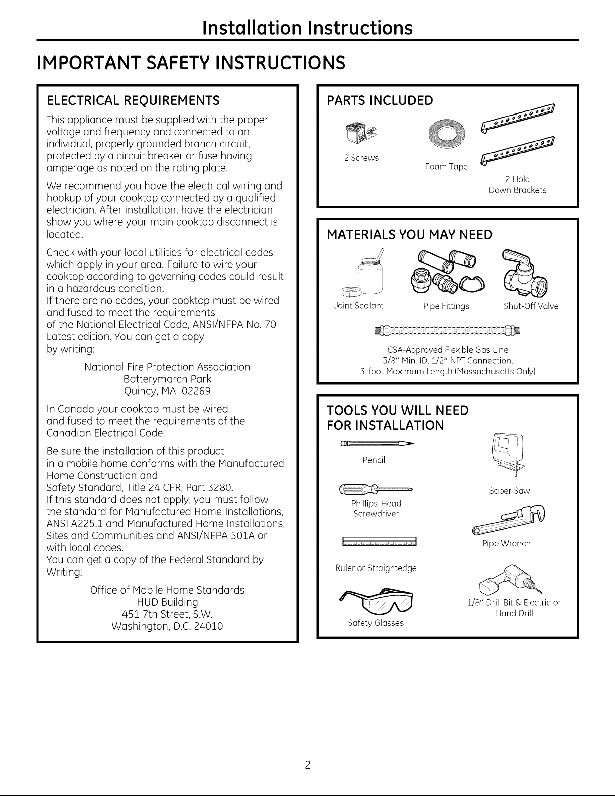
PARTS INCLUDED
2Screws
Foam Tape
MATERIALS YOU MAY NEED
Joint Sealant Pipe Fittings
CSA-Approved Flexible Gas Line
3/8" Min. ID, 1/2" NPTConnection,
3-foot Maximum Length (Massachusetts Only)
2 Hold
Down Brackets
Shut-Off Valve
InCanada your cooktop must be wired
and fused to meet the requirements of the
Canadian Electrical Code.
Be sure the installation of this product
in a mobile home conforms with the Manufactured
Home Construction and
Safety Standard, Title 24 CFR, Part 3280.
If this standard does not apply, you must follow
the standard for Manufactured Home Installations,
ANSI A225.1 and Manufactured Home Installations,
Sites and Communities and ANSI/NFPA 501A or
with local codes.
You can get a copy of the Federal Standard by
Writing:
Office of Mobile Home Standards
HUD Building
451 7th Street, S.W.
Washington, D.C. 24010
TOOLS YOU WILL NEED
FOR INSTALLATION
Pencil
Saber Saw
Phillips-Head
Screwdriver
Pipe Wrench
Ruler or Straightedge
1/8" Drill Bit & Electric or
Hand Drill
Safety Glasses
Installation Instructions
PRE-INSTALLATION CHECKLIST
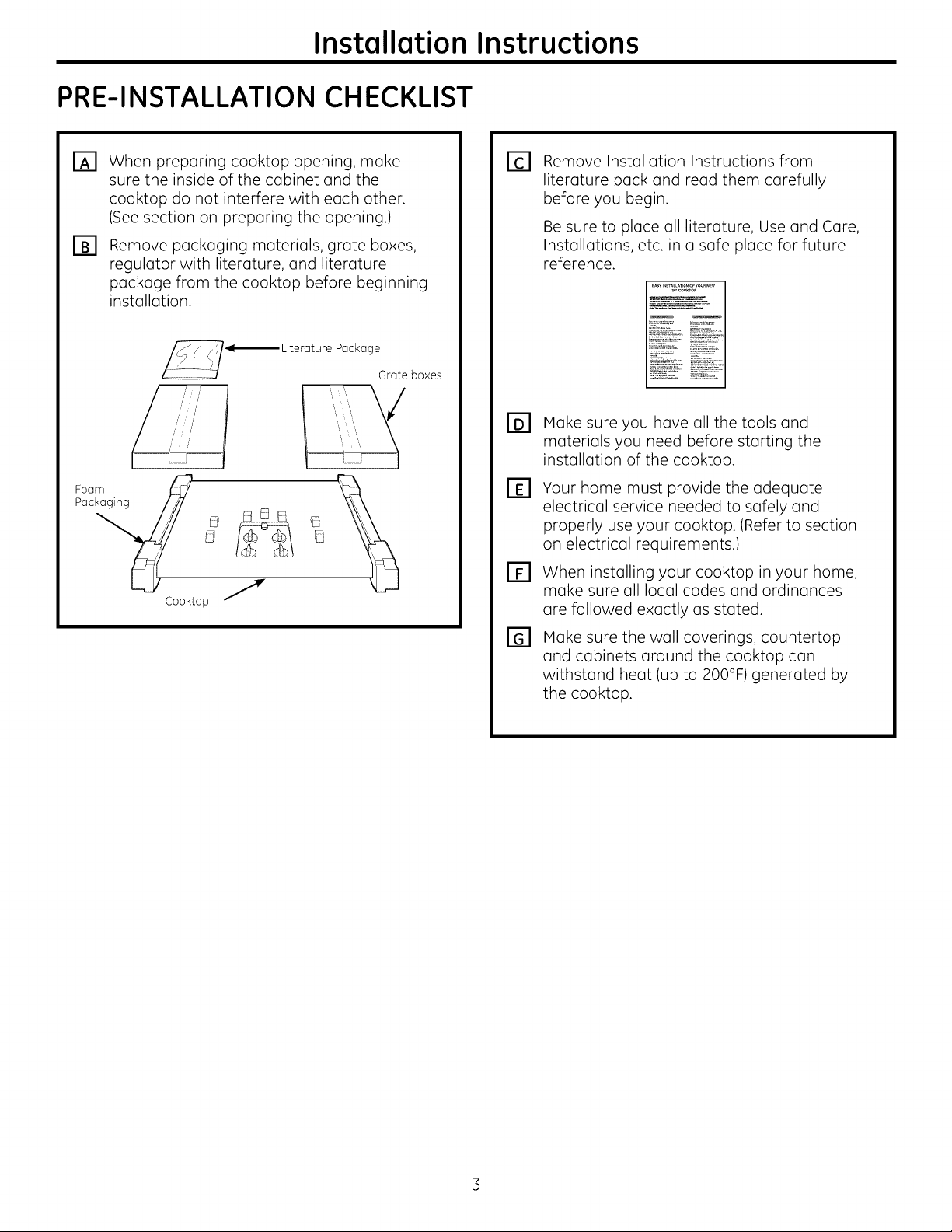
When preparing cooktop opening, make
_3
sure the inside of the cabinet and the
cooktop do not interfere with each other.
(See section on preparing the opening.)
Remove packaging materials, grate boxes,
F_
regulator with literature, and literature
package from the cooktop before beginning
installation.
Package
Foam_ _ _X
Pac _ _ _ El
Cool<top J
Grate boxes
Remove Installation Instructions from
E1
literature pack and read them carefully
before you begin.
Be sure to place all literature, Use and Care,
Installations, etc. in a safe place for future
reference.
Make sure you have all the tools and
r61
materials you need before starting the
installation of the cooktop.
Your home must provide the adequate
[]
electrical service needed to safely and
properly use your cooktop. (Refer to section
on electrical requirements.)
When installing your cooktop in your home,
FF1
make sure all local codes and ordinances
are followed exactly as stated.
Make sure the wall coverings, countertop
and cabinets around the cooktop can
withstand heat (up to 200°F) generated by
the cooktop.
Installation Instructions
PREPARING THE OPENING
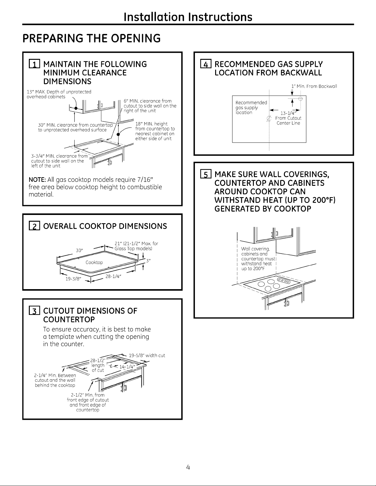
MAINTAIN THE FOLLOWING
B3
MINIMUM CLEARANCE
DIMENSIONS
15" MAX.Depth of unprotected
6" IVllN.clearance from
II cutout to side wall on the
overhead cabinets _
3-3/4" MIN.clearance from __
cutout to side wall on the -I U_h
left of the unit IF _
NOTE: All gas cooktop models require 7/16"
free area below cooktop height to combustible
material.
of the unit
18" MIN. height
S from countertop to
nearest cabinet on
either side of unit
RECOMMENDED GAS SUPPLY
LOCATION FROM BACKWALL
1" Min. From Backwall
Recommended _ '[
gas supply
location "_ 15-i/_'
_4 From Cutout
Center Line
F51 MAKE SURE WALL COVERINGS,
COUNTERTOP AND CABINETS
AROUND COOKTOP CAN
WITHSTAND HEAT (UP TO 200°F)
GENERATED BY COOKTOP
ITI OVERALL COOKTOP DIMENSIONS
30" _ Glass Top models)
19-3/8" _
21" (21-1/2" Max. for
I_l CUTOUT DIMENSIONS OF
COUNTERTOP
To ensure accuracy, it is best to make
a template when cutting the opening
in the counter.
_._ 28-i/2'
2-1/4" Min. Between -_--
cutout and the wall
behind the cooktop
! _ of cut
2-1/2" Min. from
front edge of cutout
and front edge of
countertop
length -
19-5/8" width cut
14-1
Wall covering,
cabinets and
countertop must l
withstand heat I

Installation Instructions
INSTALLING THE COOKTOP UNIT
LOCATE ELECTRICAL OUTLET AND
B3
GAS SHUT-OFF VALVE BENEATH
CABINET
LOCATE MOUNTING PARTS
Remove the hold down brackets from the
literature package.
NEVER REUSE OLD
CONNECTORS WHEN
INSTALLING THIS
UNIT.
Install a manual shut-off valve in the gas line in an
easily accessible location outside the cooktop. Be
sure you know how and where to shut off the gas
supply to the cooktop. Install the electrical outlet
12" below the countertop.
i i
shutoff :\
Valvo iElectrical
I_ s¢
Outlet 12"
Below
Countertop
[_ PROTECT SURFACE OF COOKTOP
Place a towel or tablecloth onto the
countertop. Lay the cooktop upside down onto the
protected surface.
Bottom of cooktop j
Cloth under Cooktop
_-I ATTACH BRACKETS TO COOKTOP
Remove the screw from the side of the cooktop
and screw the hold-down bracket
to the side of the cooktop unit. Repeat for opposite
side of cooktop.
Pre-drilled
Bottom of hole X _t/
Cooktop X _/
Glass
I-_ INSERT COOKTOP INTO CUTOUT
Insert the cooktop centered into the cutout
opening. Make sure the front edge of the countertop
is parallel to the cooktop. Make final check that all
required clearances are met.
Once the unit is in place, screw the
[_] ATTACH FOAM TAPE
(glass maintop models only)
Apply the foam tape around the outer edge
of the glass. Do not overlap the foam strips.
Bottom of Cooktop
_. Foam Tapes
Cooktop Glass
hold- down bracket into the cabinet sides
to secure the unit into place.
Installation Instructions
INSTALLATION--GAS CONNECTIONS
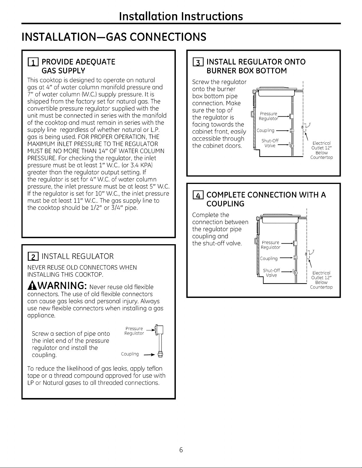
PROVIDE ADEQUATE
GAS SUPPLY
This cooktop is designed to operate on natural
gas at 4" of water column manifold pressure and
7" of water column (W.C.) supply pressure. It is
shipped from the factory set for natural gas. The
convertible pressure regulator supplied with the
unit must be connected in series with the manifold
of the cooktop and must remain in series with the
supply line regardless of whether natural or L.P.
gas is being used. FOR PROPEROPERATION, THE
MAXIMUM INLET PRESSURETO THE REGULATOR
MUST BE NO MORE THAN 14" OF WATER COLUMN
PRESSURE.For checking the regulator, the inlet
pressure must be at least 1" W.C.. (or 3.4 KPA)
greater than the regulator output setting. If
the regulator is set for 4" W.C. of water column
pressure, the inlet pressure must be at least 5" W.C.
If the regulator is set for 10" W.C., the inlet pressure
must be at least 11" W.C.. The gas supply line to
the cooktop should be 1/2" or 3/4" pipe.
_l INSTALL REGULATOR
NEVER REUSEOLD CONNECTORS WHEN
INSTALLING THIS COOKTOP.
.&WARNING: Never reuse old flexible
connectors. The use of old flexible connectors
can cause gas leaks and personal injury. Always
use new flexible connectors when installing a gas
appliance.
INSTALL REGULATOR ONTO
BURNER BOX BOTTOM
Screw the regulator
onto the burner
box bottom pipe
connection. Make
sure the top of
the regulator is
Pressure _l
Regulator'S11
facing towards the
cabinet front, easily
accessible through
the cabinet doors.
Coupling _I
Shut-Off I
Valve
COMPLETE CONNECTION WITH A
COUPLING
Complete the
connection between
the regulator pipe
coupling and
the shut-off valve.
l
Pressure
Regulator
Coupling
Shut-Off _
Valve
LI
Ii Electrical
II Outlet 12"
I Below
Countertop
I
clJ
U
II Electrical
I Outlet 12"
I Below
Countertop
Screw a section of pipe onto
Pressure _]
the inlet end of the pressure
regulator and install the
coupling.
Regulator _L_
Coupling _
To reduce the likelihood of gas leaks, apply teflon
tape or a thread compound approved for use with
LP or Natural gases to all threaded connections.
Installation Instructions
_-I CHECK FOR LEAKS
Before testing for leoks, moke sure oll burner knobs
(]re in the OFF position.
After connecting the cooktop to gas, check system
for leaks with (] manometer. If (] manometer is not
available, turn the gas supply on to the cooktop
and use (] liquid leak detector at (]lljoints and
connections to check for leaks.
Tighten all connections if necessary to prevent gas
leakage in the cooktop or supply line.
DO NOT USE OPEN FLAME TO CHECK FOR
LEAKS!
Disconnect the cooktop and its individual shut-off
valve from the gas supply piping system during any
pressure testing of that system at test pressures
greater than 1/2 psig (3.5 kP(]).
Isolate the cooktop from the gas supply piping
system by closing its individual shut-off valve
during any pressure testing of the gas supply
system at test pressures equal to or less than 1/2
psig (3.5 kP(]).
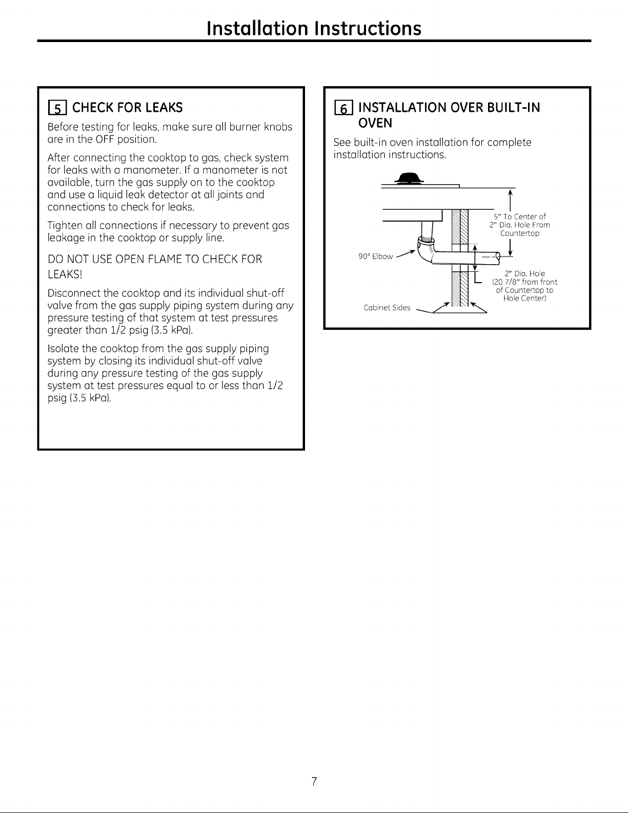
INSTALLATION OVER BUILT-IN
OVEN
See built-in oven installation for complete
installation instructions.
I
t
I / _ 2" Dim.Hole From
90° Elbow _ ---
Cabinet Sides _//_KJA'\_I_,,,_
__ _ Countertop
I_ of Countertop to
_'_l Hole Center)
5" To Center of
2" Dia. Hole
L_ (20 7/8" from front
Installation Instructions
INSTALLATION--ELECTRICAL CONNECTIONS
./I,WARN ING - Disconnect oil electricol
power ot the main circuit breoker
or fuse box before instolling.
EXTENSION CORDS
Because of potential safety hazords under certoin
conditions, we strongly recommend against the
use of an extension cord. However, if you still
elect to use an extension cord, it is absolutely
necessary that it be a UL listed B-wire grounding
type applionce extension cord ond thot the
current carrying rating of the cord in amperes be
equivalent to or greoter than the branch circuit
roting. Such extension cords ore obtoinoble
through your Iocol opplionce deoler.
IMPORTANT: (Pleosereod corefully)FOR
PERSONAL SAFETY,THIS APPLIANCE MUST BE
PROPERLY GROUNDED.
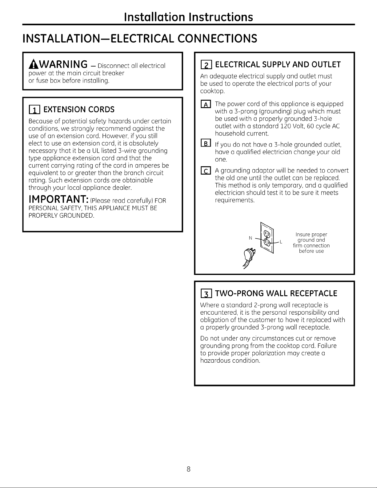
ELECTRICAL SUPPLY AND OUTLET
An odequote electricol supply ond outlet must
be used to operote the electricol ports of your
cooktop.
The power cord of this applionce is equipped
with o 3-prong (grounding) plug which must
be used with o properly grounded 3-hole
outlet with u standard 120 Volt, 60 cycle AC
household current.
If you do not hove o 3-hole grounded outlet,
hove o quolified electricion chonge your old
one.
A grounding oduptor will be needed to convert
the old one until the outlet con be reploced.
This method is only temporary, ond a qualified
electricion should test it to be sure it meets
requirements.
Insure proper
ground ond
firm connection
before use
TWO-PRONG WALL RECEPTACLE
Where a standard 2-prong wall receptacle is
encountered, it is the personal responsibility and
obligation of the customer to hove it replaced with
u properly grounded B-prong wall receptacle.
Do not under any circumstonces cut or remove
grounding prong from the cooktop cord. Failure
to provide proper polarization may create u
hazardous condition.
Installation Instructions
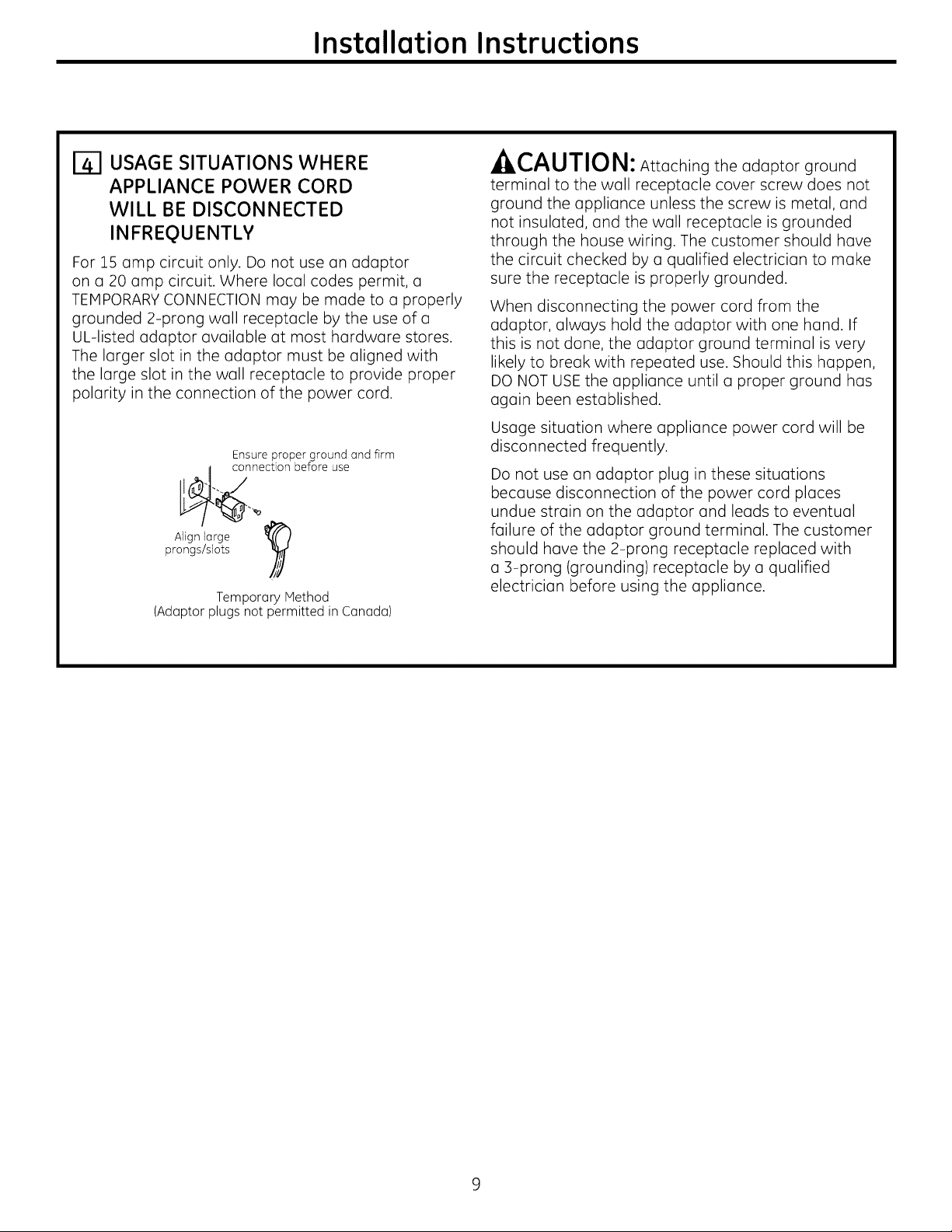
USAGE SITUATIONS WHERE
APPLIANCE POWER CORD
WILL BE DISCONNECTED
INFREQUENTLY
For 15 amp circuit only. Do not use an adaptor
on a 20 amp circuit. Where local codes permit, a
TEMPORARY CONNECTION may be made to a properly
grounded 2-prong wall receptacle by the use of a
UL-listed adaptor available at most hardware stores.
The larger slot in the adaptor must be aligned with
the large slot in the wall receptacle to provide proper
polarity in the connection of the power cord.
Ensure proper ground and firm
connection before use
prongs/slots
Align large 1_
(Adaptor plugs not permitted in Canada)
Temporary Method
A _^,|'T'|_L,
_ILI,.,/'_U/IU I_1: Attaching the adaptor ground
terminal to the wall receptacle cover screw does not
ground the appliance unless the screw is metal, and
not insulated, and the wall receptacle is grounded
through the house wiring. The customer should have
the circuit checked by a qualified electrician to make
sure the receptacle is properly grounded.
When disconnecting the power cord from the
adaptor, always hold the adaptor with one hand. If
this is not done, the adaptor ground terminal is very
likely to break with repeated use. Should this happen,
DO NOT USE the appliance until a proper ground has
again been established.
Usage situation where appliance power cord will be
disconnected frequently.
Do not use an adaptor plug in these situations
because disconnection of the power cord places
undue strain on the adaptor and leads to eventual
failure of the adaptor ground terminal. The customer
should have the 2-prong receptacle replaced with
a 3-prong (grounding) receptacle by a qualified
electrician before using the appliance.
Installation Instructions
COOKTOP BURNERS
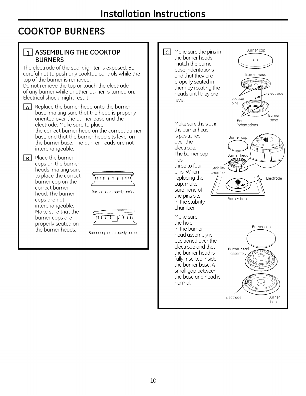
ASSEMBLING THE COOKTOP
BURNERS
The electrode of the spark igniter is exposed. Be
careful not to push any cooktop controls while the
top of the burner is removed.
Do not remove the top or touch the electrode
of any burner while another burner is turned on.
Electrical shock might result.
O0 Replace the burner head onto the burner
bose, making sure that the head is properly
oriented over the burner bose and the
electrode. IVloke sure to place
the correct burner head on the correct burner
bose and that the burner head sits level on
the burner bose. The burner heads ore not
interchangeable.
Place the burner
[]8
cops on the burner
heads, making sure
to place the correct
burner cop on the
correct burner
head. The burner
cops ore not
interchangeable.
IVloke sure that the
burner cops ore
properly seated on
the burner heads.
Burner cop properlyseated
Burner cop not properly seated
Hake sure the pins in
[]
the burner heads
match the burner
bose indentutions
and that they ore
properly seated in
them by rotating the
heuds until they ore
level.
IVlokesure the slot in
the burner head
is positioned
over the
electrode.
The burner cup
has
three to four
pins. When
replacing the
cup, make
sure none of
the pins sits
in the stmbility
chamber.
Hake sure
the hole
in the burner
head assembly is
positioned over the
electrode and that
the burner head is
fully inserted inside
the burner base. A
small gap between
the base and head is
normal.
Burner cop
Burner head
_ectrode
__Burner
Pin bose
indentations
Stobilit_
chamber _
Electrode
Burnerbose
Burner cop
Burner head
ossembl i_
lO
Electrode Burner
bose
 Loading...