

GE JGP328BEK1BB, JGP328CEK1CC, JGP328SEK1SS, JGP328WEK1WW, JGP329DET1BB Installation Guide
...Page 1
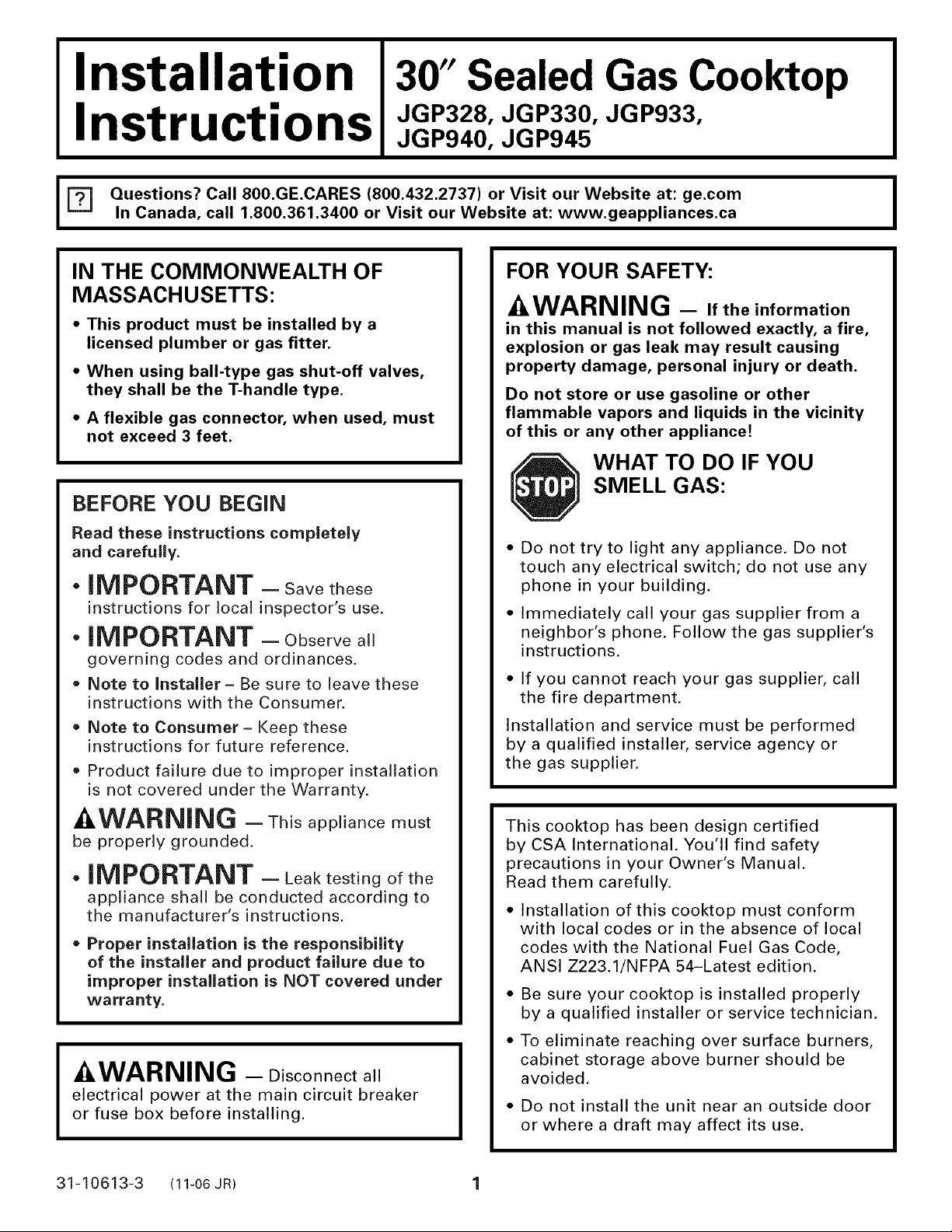
IIinstallation 130"Sealed Gas Cooktop
nstructions
JGP940,JGP94s
=_ Questions? Call 800.GE.CARES (800.432.2737) or Visit our Website at: go.cornIn Canada, call 1.800.361.3400 or Visit our Website at: www.geappliances.ca I
IN THE COMMONWEALTH OF
MASSACHUSETTS:
• This product must be installed by a
licensed plumber or gas fitter.
• When using ball-type gas shut-off valves,
they shall be the T-handle type.
• A flexible gas connector, when used, must
not exceed 3 feet.
BEFORE YOU BEGIN
Read these instructions completely
and carefully.
• iMPORTANT - Savethese
instructions for local inspector's use.
• iMPORTANT - Observeall
governing codes and ordinances.
Note to Installer - Be sure to leave these
instructions with the Consumer.
Note to Consumer - Keep these
instructions for future reference.
Product failure due to improper installation
is not covered under the Warranty.
FOR YOUR SAFETY:
-&WARNING - Iftheinformation
in this manual is not followed exactly, a fire,
explosion or gas leak may result causing
property damage, personal injury or death.
Do not store or use gasoline or other
flammable vapors and liquids in the vicinity
of this or any other appliance!
WHAT TO DO IF YOU
SMELL GAS:
Do not try to light any appliance. Do not
touch any electrical switch; do not use any
phone in your building.
Immediately call your gas supplier from a
neighbor's phone. Follow the gas supplier's
instructions.
• If you cannot reach your gas supplier, call
the fire department.
Installation and service must be performed
by a qualified installer, service agency or
the gas supplier.
-&WARNING - This appliance must
be properly grounded.
• IMPORTANT - Leak testing of the
appliance shall be conducted according to
the manufacturer's instructions.
= Proper installation is the responsibility
of the installer and product failure due to
improper installation is NOT covered under
warranty.
-&WARNING - Disconnectall
electrical power at the main circuit breaker
or fuse box before installing.
31-10613-3 (11-06 JR) 1
This cooktop has been design certified
by CSA International. You'll find safety
precautions in your Owner's Manual,
Read them carefully.
• Installation of this cooktop must conform
with local codes or in the absence of local
codes with the National Fuel Gas Code,
ANSI Z223,1/NFPA 54-Latest edition.
Be sure your cooktop is installed properly
by a qualified installer or service technician.
To eliminate reaching over surface burners,
cabinet storage above burner should be
avoided.
• Do not install the unit near an outside door
or where a draft may affect its use,
Page 2
Installation instructions
IMPORTANT SAFETY INSTRUCTIONS
ELECTRICAL REQUIREMENTS
This appliance must be supplied with the
proper voltage and frequency and connected
to an individual, properly grounded branch
circuit, protected by a circuit breaker or fuse
having amperage as noted on the rating plate.
We recommend you have the electrical wiring
and hookup of your cooktop connected by a
qualified electrician. After installation, have
the electrician show you where your main
cooktop disconnect is located.
Check with your local utilities for electrical
codes which apply in your area. Failure to
wire your cooktop according to governing
codes could result in a hazardous condition.
If there are no codes, your cooktop must be
wired and fused to meet the requirements
of the National Electrical Code, ANSI/NFPA
No. 70--Latest edition. You can get a copy
by writing:
National Fire Protection Association
Batterymarch Park
Quincy, MA 02269
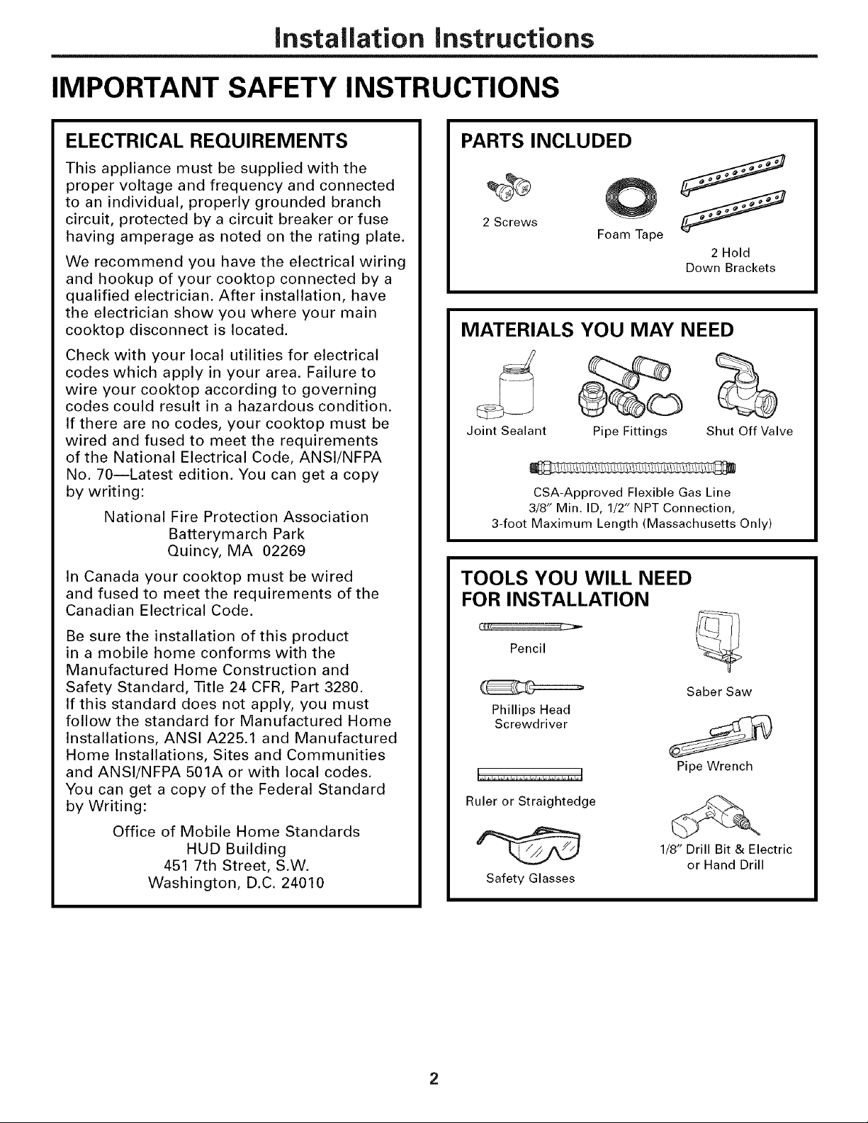
PARTS INCLUDED
2 Screws
Foam Tape
2 Hold
Down Brackets
MATERIALS YOU MAY NEED
Joint Sealant
CSA-Approved Flexible Gas Line
3/8" Min. ID, 1/2" NPT Connection,
3-foot Maximum Length (Massachusetts Only)
Pipe Fittings
Shut Off Valve
In Canada your cooktop must be wired
and fused to meet the requirements of the
Canadian Electrical Code.
Be sure the installation of this product
in a mobile home conforms with the
Manufactured Home Construction and
Safety Standard, Title 24 CFR, Part 3280.
If this standard does not apply, you must
follow the standard for Manufactured Home
Installations, ANSI A225.1 and Manufactured
Home Installations, Sites and Communities
and ANSI/NFPA 501A or with local codes.
You can get a copy of the Federal Standard
by Writing:
Office of Mobile Home Standards
HUD Building
451 7th Street, S.W.
Washington, D.C. 24010
TOOLS YOU WILL NEED
FOR INSTALLATION
Pencil
Saber Saw
Phillips Head
Screwdriver
Pipe Wrench
Ruler or Straightedge
1/8" Drill Bit & Electric
or Hand Drill
Safety Glasses
Page 3
Installation Instructions
PRE-INSTALLATION CHECKLIST
[]
When preparing cooktop opening,
make sure the inside of the cabinet and
the cooktop do not interfere with each
other. (See section on preparing the
opening.)
Remove packaging materials, grate
[]
boxes, regulator with literature, and
literature package from the cooktop
before beginning installation.
[] Remove Installation Instructions from
literature pack and read them carefully
before you begin.
Be sure to place all literature, Use and
Care, Installations, etc. in a safe place for
future reference.
Foam . j_
Pac_ @
Cooktop /
_-_ Literature Package
Grate boxes
[] Make sure you have all the tools and
materials you need before starting the
installation of the cooktop.
[] Your home must provide the adequate
electrical service needed to safely and
properly use your cooktop. (Refer to
section on electrical requirements.)
[] When installing your cooktop in your
home, make sure all local codes and
ordinances are followed exactly as
stated.
Make sure the wall coverings,
[]
countertop and cabinets around the
cooktop can withstand heat (up to
200°F) generated by the cooktop.
Page 4
Installation Instructions
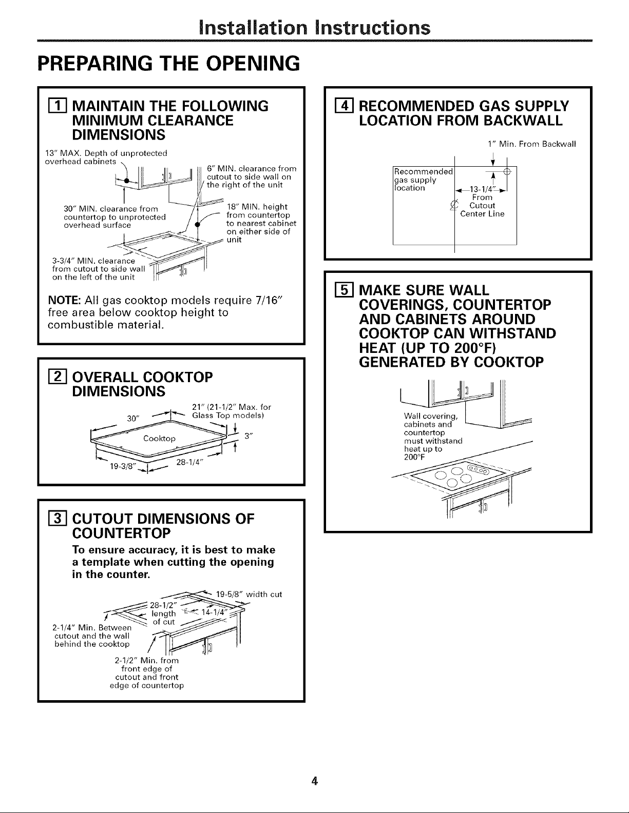
PREPARING THE OPENING
Ill MAINTAIN THE FOLLOWING
MINIMUM CLEARANCE
DIMENSIONS
13" MAX. Depth of unprotected
overhead cabinets _
3-3/4,,MINclear
fro _hc t_teOft'ut__hSeiden,_a,,
6" MIN. clearance from
cutout to side wall on
/ the right of the unit
18" MIN. height
S from countertop
to nearest cabinet
on either side of
unit
NOTE: All gas cooktop models require 7/16"
free area below cooktop height to
combustible material.
_-I OVERALL COOKTOP
DIMENSIONS
. 21" (21-1/2" Max. for
30" _ Glass Top i_nodels)
L
[_] RECOMMENDED GAS SUPPLY
LOCATION FROM BACKWALL
1" Min. From Backwall
Recommended
gas supply
location
_,_ 13-1_
From
Cutout
Center Line
I-_ MAKE SURE WALL
COVERINGS, COUNTERTOP
AND CABINETS AROUND
COOKTOP CAN WITHSTAND
HEAT (UP TO 200°F)
GENERATED BY COOKTOP
Wall covering,
cabinets and
countertop
must withstand /
heat up to
19-3/8" _
E_ CUTOUT DIMENSIONS OF
COUNTERTOP
To ensure accuracy, it is best to make
a template when cutting the opening
in the counter.
19-5/8" width cut
_ wee_n_ 28-1/2"
of cut/
2-1/4" Min. Bet
cutout and the wall
behind the cooktop
edge of countertop
2-1/2" Min. from
cutout and front
length _ 14-1/4"
front edge of
4
Page 5
Installation Instructions
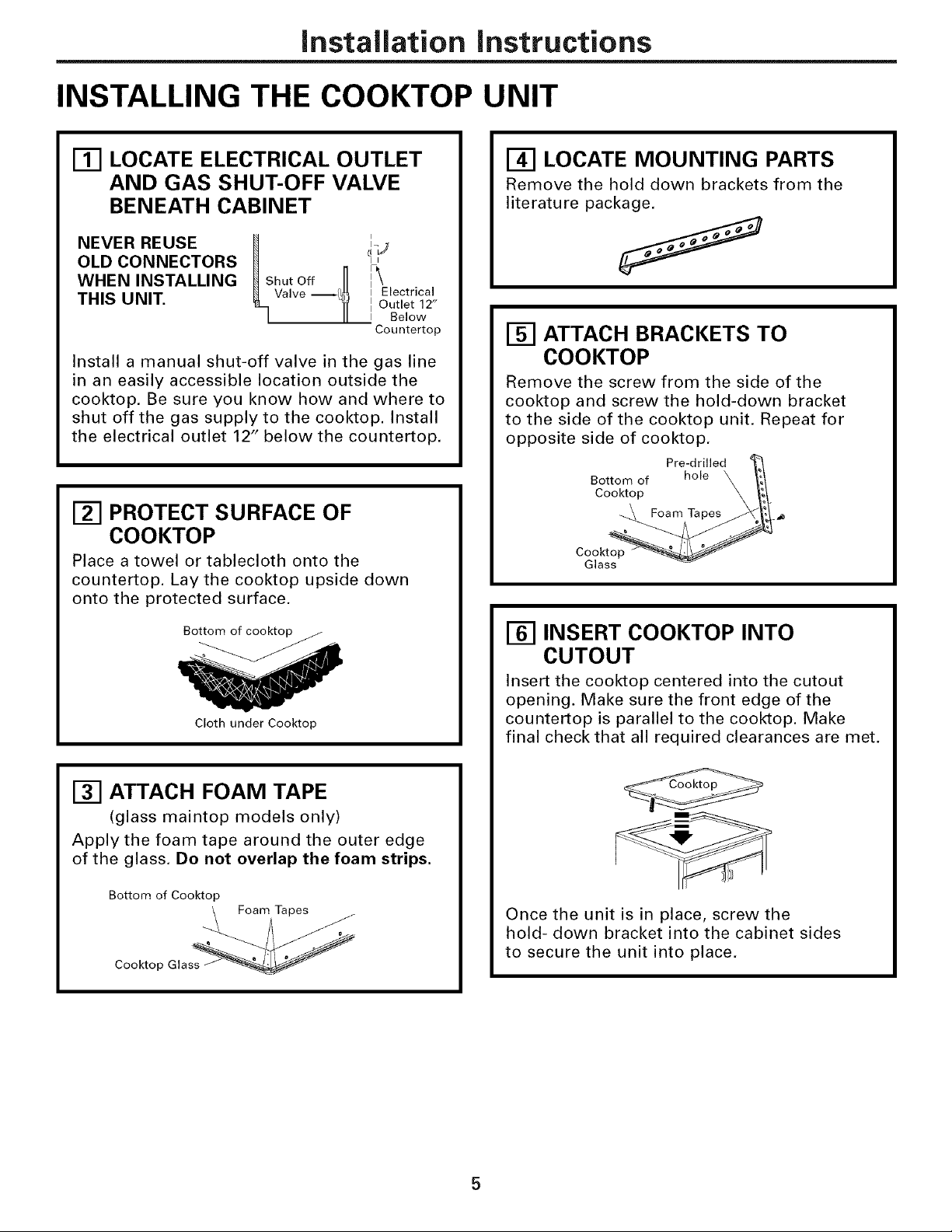
INSTALLING THE COOKTOP UNIT
Ill LOCATE ELECTRICAL OUTLET
AND GAS SHUT-OFF VALVE
BENEATH CABINET
NEVER REUSE
OLD CONNECTORS
WHEN INSTALLING
THIS UNIT.
Install a manual shut-off valve in the gas line
in an easily accessible location outside the
cooktop. Be sure you know how and where to
shut off the gas supply to the cooktop. Install
the electrical outlet 12" below the countertop,
_Shut Off H
Valve _[_
iJ
II
[ Outlet 12"
I Below
Countertop
[] PROTECT SURFACE OF
COOKTOP
Place a towel or tablecloth onto the
countertop. Lay the cooktop upside down
onto the protected surface.
_-I LOCATE MOUNTING PARTS
Remove the hold down brackets from the
literature package.
I-_ ATTACH BRACKETS TO
COOKTOP
Remove the screw from the side of the
cooktop and screw the hold-down bracket
to the side of the cooktop unit. Repeat for
opposite side of cooktop,
Pre-drilled 4_
Bottom of hole _ f[_/
Cooktop X 1_1"
Foam Ta pe___l_, _
Cooktop _
Botto f cook_
Cloth under Cooktop
[] ATTACH FOAM TAPE
(glass maintop models only)
Apply the foam tape around the outer edge
of the glass. Do not overlap the foam strips.
Bottom of Cooktop
Foam Tapes
Cooktop Glass
[] INSERT COOKTOP INTO
CUTOUT
Insert the cooktop centered into the cutout
opening. Make sure the front edge of the
countertop is parallel to the cooktop. Make
final check that all required clearances are met.
Once the unit is in place, screw the
hold- down bracket into the cabinet sides
to secure the unit into place,
Page 6
Installation Instructions
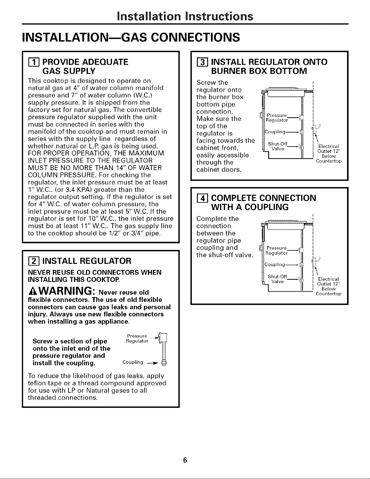
INSTALLATION--GAS CONNECTIONS
Ill PROVIDE ADEQUATE
GAS SUPPLY
This cooktop is designed to operate on
natural gas at 4" of water column manifold
pressure and 7" of water column (W.C.)
supply pressure. It is shipped from the
factory set for natural gas. The convertible
pressure regulator supplied with the unit
must be connected in series with the
manifold of the cooktop and must remain in
series with the supply line regardless of
whether natural or L.P. gas is being used.
FOR PROPER OPERATION, THE MAXIMUM
INLET PRESSURE TO THE REGULATOR
MUST BE NO MORE THAN 14" OF WATER
COLUMN PRESSURE. For checking the
regulator, the inlet pressure must be at least
1" W.C.. (or 3.4 KPA) greater than the
regulator output setting. If the regulator is set
for 4" W.C. of water column pressure, the
inlet pressure must be at least 5" W.C. If the
regulator is set for 10" W.C., the inlet pressure
must be at least 11" W.C.. The gas supply line
to the cooktop should be 1/2" or 3/4" pipe.
_-I INSTALL REGULATOR
NEVER REUSE OLD CONNECTORS WHEN
INSTALLING THIS COOKTOP.
-&WARNING: Never reuse old
flexible connectors. The use of old flexible
connectors can cause gas leaks and personal
injury. Always use new flexible connectors
when installing a gas appliance.
[] INSTALL REGULATOR ONTO
BURNER BOX BOTTOM
Screw the
regulator onto
the burner box
bottom pipe
connection.
Make sure the
top of the
regulator is
facing towards the
cabinet front,
easily accessible
through the
cabinet doors.
Pressure _
Regulator
Coupling_
Shut-Off q,
Valve _*_
I
I
J I
_TJ
LI
i\
II Electrical
I Outlet 12"
I Below
Countertop
_-I COMPLETE CONNECTION
WITH A COUPLING
I
Complete the
connection
between the
regulator pipe
coupling and
the shut-off valve.
"I
Pressure
Regulator
Coupling_[_
Shut-Off f/,
Valve _
I
JqJ
LI
II Electrical
I Outlet 12"
I Below
Countertop
Screw a section of pipe
Pressure _-]
onto the inlet end of the
pressure regulator and
install the coupling.
Regulator _J
Coupling _
To reduce the likelihood of gas leaks, apply
teflon tape or a thread compound approved
for use with LP or Natural gases to all
threaded connections.
6
Page 7
Installation instructions
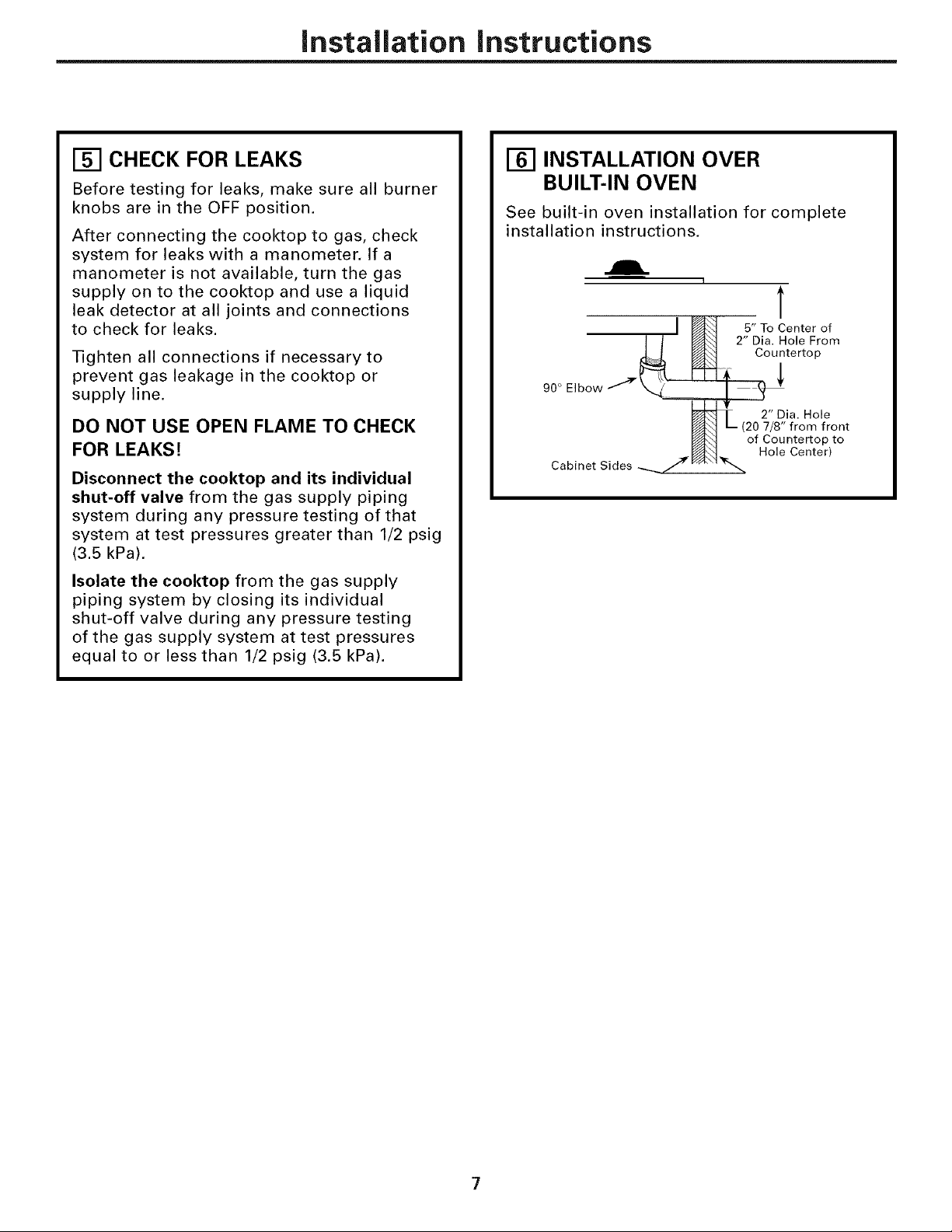
[] CHECK FOR LEAKS
Before testing for leaks, make sure all burner
knobs are in the OFF position.
After connecting the cooktop to gas, check
system for leaks with a manometer. If a
manometer is not available, turn the gas
supply on to the cooktop and use a liquid
leak detector at all joints and connections
to check for leaks.
Tighten all connections if necessary to
prevent gas leakage in the cooktop or
supply line.
DO NOT USE OPEN FLAME TO CHECK
FOR LEAKS!
Disconnect the cooktop and its individual
shut-off valve from the gas supply piping
system during any pressure testing of that
system at test pressures greater than 1/2 psig
(3.5 kPa).
Isolate the cooktop from the gas supply
piping system by closing its individual
shut-off valve during any pressure testing
of the gas supply system at test pressures
equal to or less than 1/2 psig (3.5 kPa).
INSTALLATION OVER
BUILT-IN OVEN
See built-in oven installation for complete
installation instructions.
I
T
IN 5,, oCenterof
/ / _ 2" Dia. Hole From
_ Countertop
90 ° Elbow _X._. I _b'
Cabinet Sides -..._/J'!_ _-'A_'7_
,f
2" Dia. Hole
_1 L_ (20 7/8" from front
_'_'1 of Countertop to
F/;_] Hole Center)
Page 8
Installation Instructions
INSTALLATION--ELECTRICAL CONNECTIONS
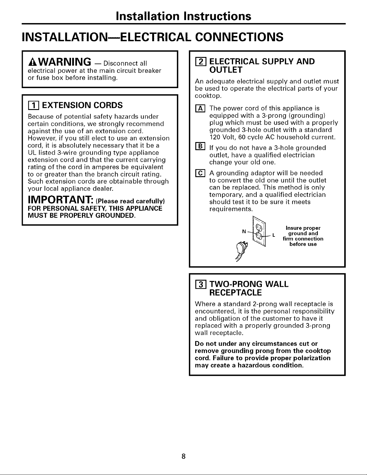
-&WARNING - Disconnectall
electrical power at the main circuit breaker
or fuse box before installing.
[] EXTENSION CORDS
Because of potential safety hazards under
certain conditions, we strongly recommend
against the use of an extension cord.
However, if you still elect to use an extension
cord, it is absolutely necessary that it be a
UL listed 3-wire grounding type appliance
extension cord and that the current carrying
rating of the cord in amperes be equivalent
to or greater than the branch circuit rating.
Such extension cords are obtainable through
your local appliance dealer.
IMPORTANT: (Please read carefully)
FOR PERSONAL SAFETY, THIS APPLIANCE
MUST BE PROPERLY GROUNDED,
_-I ELECTRICAL SUPPLY AND
OUTLET
An adequate electrical supply and outlet must
be used to operate the electrical parts of your
cooktop.
The power cord of this appliance is
[]
equipped with a 3-prong (grounding)
plug which must be used with a properly
grounded 3-hole outlet with a standard
120 Volt, 60 cycle AC household current.
[]
If you do not have a 3-hole grounded
outlet, have a qualified electrician
change your old one.
A grounding adaptor will be needed
[]
to convert the old one until the outlet
can be replaced. This method is only
temporary, and a qualified electrician
should test it to be sure it meets
requirements.
N L ground and
Insure proper
firm connection
before use
[] TWO-PRONG WALL
RECEPTACLE
Where a standard 2-prong wall receptacle is
encountered, it is the personal responsibility
and obligation of the customer to have it
replaced with a properly grounded 3-prong
wall receptacle.
Do not under any circumstances cut or
remove grounding prong from the cooktop
cord. Failure to provide proper polarization
may create a hazardous condition.
8
Page 9
Installation instructions
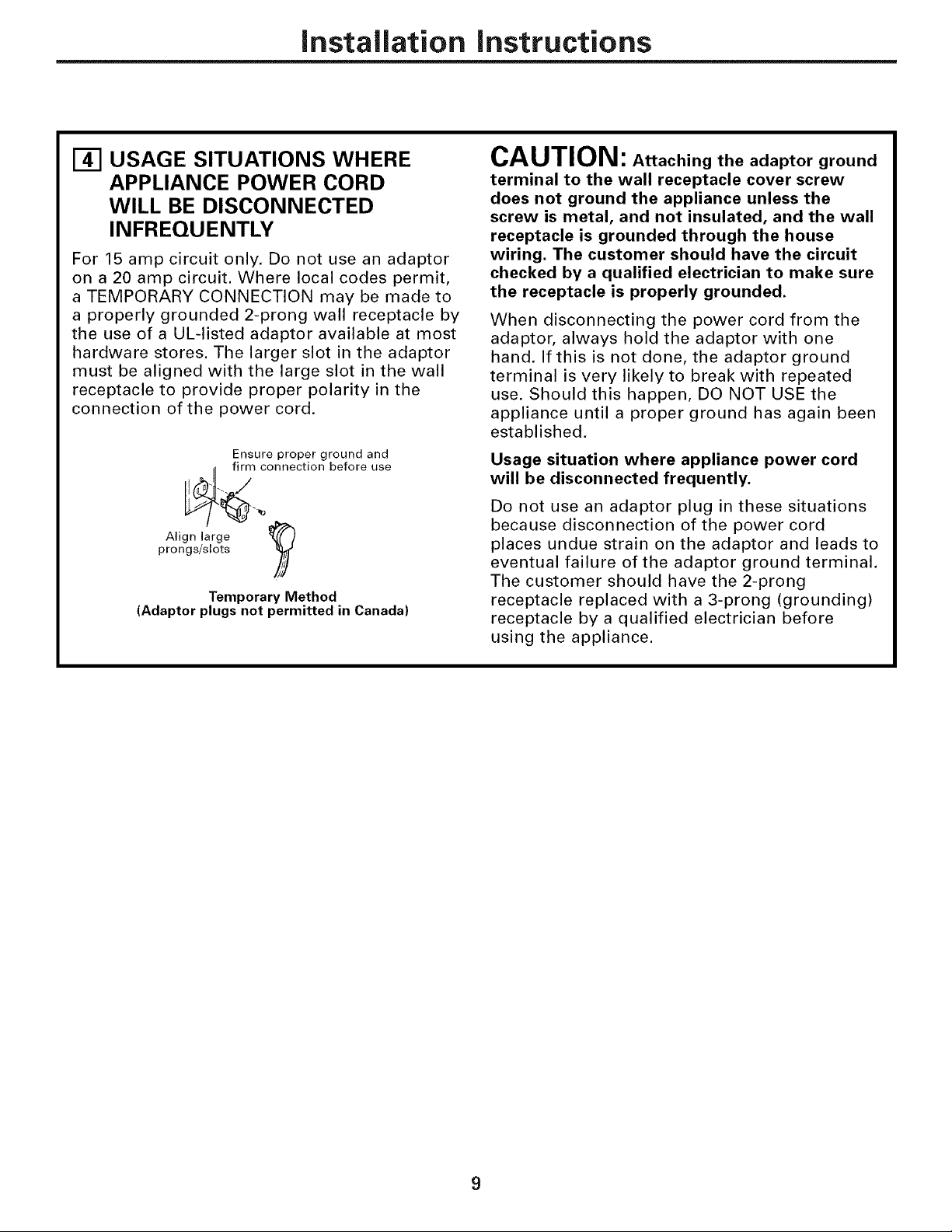
[] USAGE SITUATIONS WHERE
APPLIANCE POWER CORD
WILL BE DISCONNECTED
INFREQUENTLY
For 15 amp circuit only, Do not use an adaptor
on a 20 amp circuit. Where local codes permit,
a TEMPORARY CONNECTION may be made to
a properly grounded 2-prong wall receptacle by
the use of a UL-listed adaptor available at most
hardware stores. The larger slot in the adaptor
must be aligned with the large slot in the wall
receptacle to provide proper polarity in the
connection of the power cord,
Ensure proper ground and
firm connection before use
prongs/slots
Align large
(Adaptor plugs not permitted in Canada)
Temporary Method
CAUTION: Attaching the adaptor ground
terminal to the wall receptacle cover screw
does not ground the appliance unless the
screw is metal, and not insulated, and the wall
receptacle is grounded through the house
wiring. The customer should have the circuit
checked by a qualified electrician to make sure
the receptacle is properly grounded.
When disconnecting the power cord from the
adaptor, always hold the adaptor with one
hand. If this is not done, the adaptor ground
terminal is very likely to break with repeated
use. Should this happen, DO NOT USE the
appliance until a proper ground has again been
established.
Usage situation where appliance power cord
will be disconnected frequently.
Do not use an adaptor plug in these situations
because disconnection of the power cord
places undue strain on the adaptor and leads to
eventual failure of the adaptor ground terminal.
The customer should have the 2-prong
receptacle replaced with a 3-prong (grounding)
receptacle by a qualified electrician before
using the appliance.
Page 10
Installation instructions
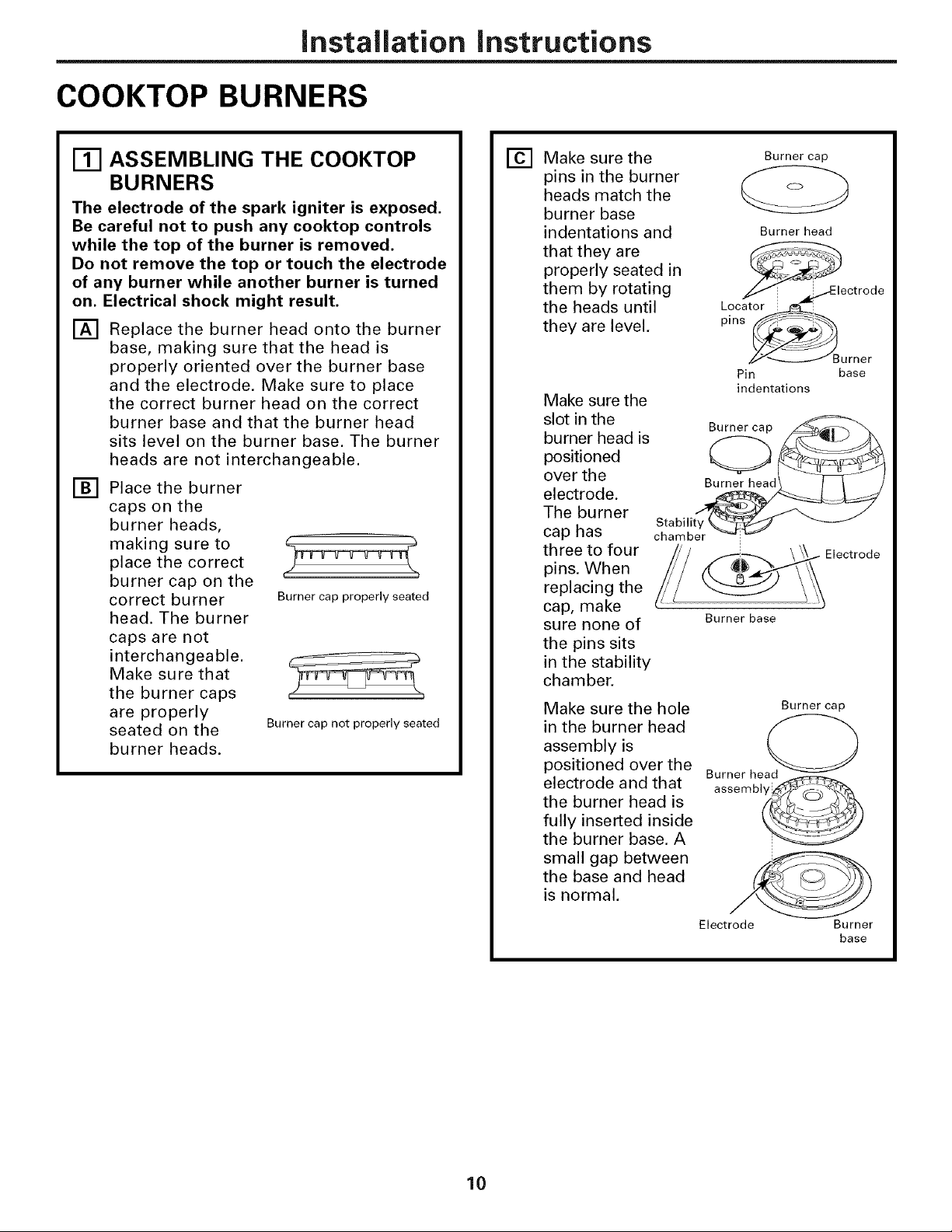
COOKTOP BURNERS
ASSEMBLING THE COOKTOP
BURNERS
The electrode of the spark igniter is exposed.
Be careful not to push any cooktop controls
while the top of the burner is removed.
Do not remove the top or touch the electrode
of any burner while another burner is turned
on. Electrical shock might result.
[] Replace the burner head onto the burner
base, making sure that the head is
properly oriented over the burner base
and the electrode. Make sure to place
the correct burner head on the correct
burner base and that the burner head
sits level on the burner base. The burner
heads are not interchangeable.
[] Place the burner
caps on the
burner heads,
making sure to
place the correct
burner cap on the
correct burner
head. The burner
caps are not
interchangeable.
Make sure that
the burner caps
are properly
seated on the
burner heads.
Burner cap properly seated
Burner cap not properly seated
Make sure the
] Burner cap
pins in the burner
heads match the
burner base
indentations and
that they are
properly seated in
them by rotating
the heads until
they are level,
Make sure the
slot in the
burner head is
positioned
over the
electrode.
The burner
cap has
three to four
pins. When
replacing the
cap, make
sure none of
the pins sits
in the stability
chamber.
)
Make sure the hole
in the burner head
assembly is
positioned over the
electrode and that
the burner head is
fully inserted inside
the burner base. A
small gap between
the base and head
is normal.
cSt_abiIiLteYr_
Burner base
Burner head
Burner head
92
= i lectrode
Loca_or i_i
/,_<-_ Burner
Pin base
indentations
Burner cap
assembl@
Electrode
10
Electrode Burner
base
Page 11

Installation instructions
CHECK IGNITERS
Operation of the electric igniters should be
checked after the cool{top and supply line
have been carefully checked for leaks and
the cool{top has been connected to the
electrical power.
On models so equipped, check to be sure the
cooktop is in the UNLOCKED position.
[] Push and turn a burner valve to the LITE
position. All spark igniters will make a
series of sparks (ticking sounds), but only
the burner turned to LITE will light.
• The burner should light when gas is
available to the burner.
• Once the burner lights, it should be
turned out of the LITE position.
[] Try each valve separately until all
burners have been checked.
BURNER IGNITION
Cool{top Spark Ignition--When you turn
the cool{top knob to LITE, the spark igniter
makes a series of electric sparks (ticking
sounds) which light the burner. During a
power failure, the burners will not light
automatically. In an emergency, a cool{top
burner may be lit with a match by following
the steps below.
AWARNING: Lighting gas burners
with a match is dangerous. You should
match light the cool{top burners only in
an emergency.
On models so equipped, check to be sure the
cooktop is in the UNLOCKED position.
THE BURNER FLAMES
Turn each burner on. Flames should be blue
in color with no trace of yellow. The burner
flames should not flutter or blow away from
the burner. The flame should be no less than
1/4" on the lowest setting and no greater than
1-1/2" on highest setting.
1/4" to Cooktop Burner
1-1/2"
Burners should be checked frequently
^_^nn m|n m1-,_
AUkw rtl lll l ( If you attemptto
measure the flame, please use caution,
Burns could result,
[] BURNER GRATES
The four cooktop grates are designed for
specific positions. For maximum stability,
these grates should only be used in their
proper position: they should not be
interchanged. For your convenience, the
undersides of the left and right grates are
marked "OUTSIDE" and "INSIDE". Make sure
that the side marked "OUTSIDE" is on the
outer edge of your cooktop.
[] Light a match and hold the flame near
the burner you want to light. Wooden
matches work best.
[] Push in and turn the control knob slowly.
Be sure you are turning the correct knob
for the burner you are lighting.
NOTE: If the burner does not light within five
seconds, turn the knob off and wait one minute
before trying again.
"OUTSIDE .... INSIDE .... OUTSIDE"
edge edges edge
11
Page 12

Installation Instructions
OPERATION CHECKLIST
[] Make sure all controls are left in the OFF
position, Check to be sure the cooktop is
in the UNLOCKED position (on models
so equipped),
[] Make sure the flow of air to and from the
cooktop is unobstructed.
[] The serial plate for your cooktop is
located on the bottom of the burner box.
In addition to the model and serial
numbers, it tells you the ratings of the
burners and the type of fuel and pressure
the cooktop was adjusted for when it
left the factory.
[] When ordering parts, always include the
serial number, model number and a code
letter to ensure proper replacement parts.
[] Recheck Steps:
Double check to make sure everything
in this guide has been completed.
Rechecking steps will ensure safe
use of the cooktop.
12
Page 13

Installation instructions
MAKING THE LP CONVERSION
_-_ SAFETY INFORMATION YOU
SHOULD KNOW
The pressure regulator and burner orifices
are set for natural gas. To use Propane Gas,
the regulator and burner orifices must be
converted. The LP orifice spuds for the
cool(top burners can be located in the
literature package attached to the regulator.
CAUTION: The cool(top, as shipped
from the factory, is set for use with natural
gas. If you wish to use your cool(top with
Liquefied Petroleum (Propane) gas, you must
first replace the orifices and convert the
pressure regulator.
AWARNING: This conversion
must be performed by a qualified installer
or gas supplier in accordance with the
manufacturer's instructions and all codes
and requirements of the authority having
jurisdiction. Failure to follow instructions
could result in serious injury or property
damage. The qualified agency performing
this work assumes responsibility for the
conversion.
ADJUST YOUR COOKTOP FOR
USE WITH LP GAS
[]
Disconnect all electrical power, at the
main circuit breaker or fuse box.
[]
Shut off the gas supply to the cooktop
by closing the manual shut-off valve.
[]
Adjust the pressure regulator, by the
following instructions:
• Unscrew the cap.
• Place your thumb against the flat side
of the spring retainer and press down
to remove the retainer.
• Carefully look at the spring retainer to
locate the NAT or LP position.
Cap Gasket
[------_"" ""_L .'Ft/pr R;21 i; er
NAT. _ ........................._ Position
CAUTION: The following adjustments
must be made before turning on the burner.
Failure to do so could result in serious injury.
Be sure pressure regulator has been
converted as described in Step 2.
TOOLS YOU WILL NEED
FOR LP CONVERSION
Phillips Head
Screwdriver
Pliers
Safety Glasses
7mm Nutdriver
No. 15 Torx-Head
Driver
Small Flat-Head
Screwdriver (4mm
or 5/32" tip size,
60mm long)
Position _
Pressure Regulator
• Turn the spring retainer over so that LP
is showing on the bottom.
• Snap the retainer back into position.
• Screw the cap back onto the regulator,
13
Page 14

Installation Instructions
MAKING THE LP CONVERSION (CONT.)
CHANGE COOKTOP BURNER
ORIFICES
Remove the top
grates, burner caps,
and burner heads.
[] Remove the spark
igniters from the
burner base (if
required to access
the orifices). Using a
No. 15 "Torx" head
driver bit, remove the
screws holding the
burner base in
position.
[] Using a 7mm nut
driver, remove the
top burner orifices.
These may be
accessed through the
hole in the cooktop.
Orifice Spud Located
Through This Opening
Burner cap
Burne
head@
nor
Remove
This
Assembly
[] CHANGE COOKTOP BURNER
ORIFICES (CONT.)
NOTE: On most burners,
the orifices have a spring- Retainer
loaded retaining ring Ring
around the hex head to
hold the orifice in the nut
driver during installation
and removal. A slight amount of force is
required to push the nut driver down over
the ring.
Spark igniter base
18,000BTUBurner
(on somemodels)
Burner
cap
_Burner
_head
Burner_._J
base
Spark igniter
14
Page 15

Installation instructions
CHANGE COOKTOP BURNER
[]
ORIFICES (CONT.)
[]
Locate the LP/Propane orifices shipped
inside the literature package. They
will have a digit number and the letter
"L" on the side. (Important: Save the
orifices removed from the appliance
for future use.)
Each orifice will show a series of
engraved marks, (I, II, III, X or none),
located on the top.
These marks denote the precise location of
each orifice to the cooktop burner.
OOOO
oi
Left Rear Left Front RightFront
Model Orifice Orifice Orifice
JGP328 II II II
JGP330 II II III
JGP933 III II X
18,000 BTU/HR Burner (on some models)
O he 18,000 BTU/HR burner has two orifices
NOTE: The main orifice is located low in the
center of the burner while the simmer orifice
is located higher behind the center of the
burner.
with markings located in the sides only.
(See rating plate on bottom of appliance).
Simmer
orifice
Main orifice
JGP940 III II X
JGP945 III II Replace: With:
Install the LP/Propane orifices in
[]
their precise locations as noted in the
illustrations above.
[]
Return the natural gas orifices to the
bracket and reattach the bracket and the
instruction sheet to the pressure
regulator using the screw removed
previously.
Replace the burner bases, heads, caps
[]
and top grates. (NOTE: When re-attachinq
the burner bases to qlass top units,
tiqhten screws to a maximum of
10 in.-Ibs torque.)
Main 206XN --) I08XL
Simmer 57N --). 34L
15
Page 16

Installation instructions
MAKING THE LP CONVERSION (CONT.)
ADJUST BURNER FLAMES
[]
Turn all burners full on and check the
[]
flames. They should be blue in color with
some yellow tipping at the ends of the
flame. Foreign particles in the gas line
may cause an orange flame at first, but
this will soon disappear.
NOTE: For the 18,000 BTU/HR burner (on
some models) the cooktop burner knob
should be turned to the setting before
the lowest setting. This will ensure that
the entire burner is operating.
[]
Turn the cooktop burner knob to the
lowest setting while observing the flame.
Adjust the low flame setting using the valve
bypass screw as follows:
Low-setting adjustments must be made
with two other burners in operation on
a medium setting. This prevents the low
flame from being set too low, resulting in
the flame being extinguished when other
burners are turned on.
[] To adjust the flame,
remove the knobs.
Insert a screwdriver
through the access
hole in valve switch.
Engage adjustment
screw in valve, Refer
to the illustration
below that matches
the adjustment screw
location for your
model.
• If the flames were
too small or
fluttered, open the
valve more than
the original setting.
• If the flames blew
away from the burner, close the valve
more than the original setting.
[] Make the adjustment by slowly turning
the screw until flame appearance is
correct.
[] Testing Flame Stability:
Test 1 - Turn the knob from "HI" to the
lowest setting quickly. If the
flame goes out at the lowest
setting, increase the flame size
and test again.
Test 2 - With the burner on the lowest
setting, open and close the
cabinet door under the cooktop.
If the flame is extinguished by
the air currents created by the
door movement, increase the
flame height and test again.
[] Flame Recheck:
After the adjustment is made, turn all burners
off. Ignite each burner individually. Observe
the flame at the "HI" position. Rotate the
valve to the lowest setting and be sure that
the flame size decreases as the valve is
rotated counterclockwise.
TO CONVERT THE COOKTOP BACK TO
NATURAL GAS, REVERSE THE STEPS
UNDER MAKING THE LP CONVERSION.
Once the conversion is complete and
checked ok, fill out the LP sticker and
include your name, organization and date
conversion was made. Apply the sticker
near the cooktop gas inlet opening to alert
others in the future that this appliance has
been converted to LP gas. If converting back
to natural gas from LP, please remove the
sticker so others know the appliance is set
to use natural gas.
16
Page 17

Instructions
Table de cuisson scellee
d'installation
au gaz de 76 cm (30")
JGP328, JGP330, JGP933,
JGP940, JGP945
I[_ Questions? Appelez le Centre de reponse 1.800.361.3400 ou visitez notre site
AVANT DE COMMENCER
Avant de commencer, lisez attentivement la
totalite de ces instructions.
• iMPORTANT - Conservezcos
instructions pour votre inspecteur local.
• iMPORTANT - Respecteztoutes
les ordonnances et les codes Iocaux.
= Note a I'installateur - Assurez-vous de
laissez ces instructions au consommateur.
• Note au consommateur - Conservez ces
instructions pour reference future.
• La garantie ne couvre aucune panne due
une mauvaise installation.
_AVERTISSEMENT -
Cet appareil dolt _tre bien mis a la terre.
• iMPORTANT - vousdevez
verifier que cet appareil n'ait pas de fuite
conformement aux instructions du
fabricant.
• L'installateur est responsable d'une bonne
installation et la garantie ne couvre aucune
panne due a une mauvaise installation.
._AVERTISSEIVIENT -
Debranchez tout courant electrique au niveau
du disjoncteur de la maison ou de la boite
fusibles avant d'installer.
Web a I'adresse :www, electromenagersge,ca
POUR VOTRE SECURITE
_AVERTISSEMENT -
Si vous ne suivez pas exactement les
instructions de ce manuel, vous risquez
d'occasionner un incendie, une explosion
ou une fuite de gaz, qui peuvent provoquer
des dommages materiels, des blessures
corporelles ou la mort.
Ne conservez pas ou n'utilisez jamais
d'essence ou d'autres liquides ou vapeurs
inflammables a proximite de cet appareil
ou de tout autre appareil menager!
CI QUE VOUS DEVEZ
FAIRE SI VOUS SENTEZ
LE GAZ :
• N'essayez jamais d'allumer un appareil
electromenager. Ne touchez a aucun
commutateur d'electricite, n'utilisez jamais
un telephone dans votre b_timent.
• Appelez immediatement votre fournisseur
de gaz a I'aide du telephone d'un voisin.
Suivez les instructions de votre fournisseur
de gaz.
• Si vous ne pouvez pas entrer en contact
avec votre fournisseur de gaz, appelez
les pompiers.
L'installation et le service de votre table de
cuisson doivent _tre faits par un installateur
qualifie, un technicien de service ou votre
fournisseur de gaz.
I
31-10613-3 (11-o6 JR) 1
Page 18

instructions d'instaliation
INSTRUCTIONS IMPORTANTES DE SI CURITI
La conception de votre table de cuisson a ete
approuve par I'ACNOR International. Vous
trouverez des precautions a prendre en
matiere de securite dans votre Guide
d'utilisation et de soins. Lisez-les
attentivement.
• L'installation de votre table de cuisson
doit se conformer aux codes Iocaux ou, en
I'absence de codes Iocaux, au National Fuel
Gas Code, ANSI Z223,1/NFPA 54 Derniere
edition.
• Assurez-vous que votre table de cuisson
soit bien installee par un installateur qualifie
ou un technicien de service.
• Pour eliminer tout mouvement corporel
au dessus des brQleurs de votre table de
cuisson, evitez de placer des armoires de
cuisine au dessus des brQleurs.
• N'installez jamais votre appareil pres d'une
porte d'entree ou dans un emplacement ou
un courant d'air peut g6ner son usage.
PII CES COMPRISES
Bandes de mousse 2 Supports de
(Pour les modules & fixation
surface en verre
seulement)
MATI RIAUX DONT VOUS POUVEZ
AVOIR BESOIN
Agent de scellement Raccords de tuyaux
de tuyau
Raccord flexible de gaz approuve par I'ACNOR
DI min 3/8", Jonction NPT 1/2
Robinet
d'alimentation de gaz
BESOINS D'ELECTRICITE
Cet appareil menager doit _tre livre avec le
bon voltage et la bonne frequence et branche
son propre circuit de derivation bien mis
la terre, protege par un disjoncteur ou un
fusible qui ont I'amperage note sur la plaque
mineralogique de votre appareil.
Nous vous recommandons de faire brancher
le c_blage electrique et la fiche de votre
cuisiniere par un electricien qualifi& Apres
I'installation, demandez a I'electricien de vous
montrer I'emplacement de votre coupe-circuit
principal.
Demandez a votre entreprise de services
publics les codes electriques en vigueur
dans votre region. En ne c_blant pas votre
cuisiniere conformement aux codes en
vigueur, vous provoquez une situation
dangereuse. En I'absence de codes, vous
devez c_bler et isoler votre cuisiniere
conformement aux exigences du Canadian
Electrical Code,
OUTILS DONT VOUS AUREZ
BESOINS
Crayon
Scie sauteuse
Tournevis Phillips
Regle ordinaire ou de
verification
Lunettes de securite
Cle a tuyau
Perceuse a main ou
electrique et foret de 1/8po
Page 19

Instructions d'instaliation
LISTE DE VITRIFICATION AVANT INSTALLATION
[]
Pour preparer I'ouverture de la surface
de cuisson, vous devez vous assurer
que I'interieur de I'armoire ne touche
pas la table de cuisson (consultez la
section sur la preparation de
I'ouverture).
[]
Enlevez les materiaux d'emballage, les
boites de grille, le regulateur avec sa
documentation et la documentation de
votre table de cuisson avant de
commencer a I'installer.
_ Documentation Boites de
an ,_o_sse /// _ _ _)
Emballage _ _ =f"
Table de/"
cuisson
ille
Enlevez les instructions d'installation
[]
de la trousse de documentation et
lisez-les soigneusement avant de
commencer.
Assurez-vous de bien ranger toute la
documentation, le manuel d'utilisation
et d'entretien, etc. dans un endroit sQr
pour reference future.
Assurez-vous d'avoir tousles outils et
[]
tous les materaux necessaires avant de
commencer a installer votre table de
cuisson.
Votre maison doit 6tre alimentee en
[]
courant electrique adequat pour vous
permettre de bien utiliser en toute
securite votre table de cuisson.
(Consultez la section sur les besoins
d'electricit&)
Pour installer votre table de cuisson
[]
dans votre maison, assurez-vous de
vous conformer scrupuleusement
tousles codes eta toutes les
ordonnances locales.
Assurez-vous que les rev_tements
[]
de mur, le comptoir et les armoires
autour de la table de cuisson puissent
supporter la chaleur [pouvant atteindre
93°C (200°F)] produite par la table de
cuisson.
Page 20

instructions d'installation
PRI PARATION DE L'OUVERTURE
Ill vous DEVEZ RESPECTER LES
DEGAGEMENTS MINIMAUX
SUlVANT
Profondeur max de 33 cm (13") des
armoires en surplomb non protegees
surplomb_oanpr
Degagement min "_'__
REMARQUE : tous les modeles de surface
cuisson au gaz requierent un degagement
de 1,1 cm (7/16 po) sous la hauteur de la
surface pour la matiere combustible.
Degagement rain. de
15 crn (6") decoupage
au tour de c6te ,_
droite de I'appareil
Hauteur rain
f de 45 crn (18")
, du comptoir
I'armoire la
de chaque
c6te de
plus proche
I'appareil
_-I DIMENSIONS DU DI_COUPAGE
DE LA TABLE DE CUlSSON
76 cm
49 cm (19-3/8")_
53 cm (21") (54,6 cm [21-1/2"]
max. pour table de cuisson
en verre)
8 cm (3")
72 cm (28-1/4")
[] EMPLACEMENT
RECOMMANDE DE
UALIMENTATION DE G.AZ A
PARTIR DU MUR ARRIERE
2.5 cm (1") min. du mur arri_re
m ,ace entI
recornmande de
I'alimentation 1_33.7 crn4.-
de gaz _,4(13-1/4") Du
@ ASSUREZ.-VOUS QUE
LES REVETEMENTS MUR, LE
COMPTOIR ET LES ARMOIRES
AUTOUR DE LA TABLE DE
CUlSSON PUlSSENT
SUPPORTER LA CHALEUR
(POUVANT ATTEINDRE 93°C
[200°F])
Les rev_tements de
mur, les armoires et
le com ptoir doivent
pouvolr supporter
une chaleru pouvant /
_di decoupage
| a la ligne
/ du centre
[] DIMENSIONS TOTALES DE
LA TABLE DE CUlSSON
Pour assurer la justesse du decoupage,
il vaut mieux faire un gabarit pour
couper I'ouverture dans le comptoir.
72,4 cm (28-1/2 po)
Iongueur du decoupage
Distance min de
5,7 cm (2-1/4")
de decoupage au
mur derriere la
table de cuisson
decoupagede I'arr&te avant
6,4 crn (2-1/2") Distance
min. de I'ar_te avant du
de la table de cuisson
Largeur du decoupage
49,8 cm (19-5/8")
4
Page 21

Instructions d'instaliation
INSTALLATION LA UNITI DE LA TABLE DE CUISSON
_-I PLACEZ LA PRISE
D'ALIMENTATION
I_LECTRIQUE ET LE ROBINET
D'ALIMENTATION DE GAZ
AU-DESSOUS DE L'ARMOIRE
DEsN'UTIUSEZRAcCORDsJAMAIS! iJ,,
USAGI_S POUR alimen
INSTALLER CET _' tation?t \illPrise30 cmelectrique(12")
APPAREIL. isousle
Montez le robinet d'alimentation manuel sur
le tuyau de gaz a un emplacement facile
atteindre en dehors de la table de cuisson.
Assurez-vous de savoir ou et comment
couper I'alimentation de gaz a la table de
cuisson. Montez la prise electrique 30 cm
(12") au-dessous du comptoir.
Robinet I] ,'_
comptoir
_-I PROTI_GEZ LA SURFACE DE
LA TABLE DE CUlSSON
Placez une serviette ou un torchon sur le
comptoir. Posez la table de cuisson a I'envers
sur la surface protegee.
Envers de la table de cuissonj
Linge sous la table de cuisson
_-_ ATTACHEZLA BANDE DE MOUSSE
(modeles de la table de verre seulement)
Appliquez la bande de mousse autour du
bord exterieur du verre. Ne superposez pas
les bandes de mousse.
_-I TROUVEZ LES PIECES DE
MONTAGE
Retirez les supports de fixation de la trousse
de documentation.
[] FIXEZ LES SUPPORTS DE
FIXATION A LA TABLE DE
CUlSSON
Enlevez la vis d'un c6te de la table de
cuisson, vissez un support de fixation a un
c6te de la table de cuisson. Repetez la m_me
operation de I'autre c6te de la table de
cuisson.
Support
de fixation \ _tt
Bas de la table \ I_,I
de ouisson Bandes de _-t_"
mousse _f _
Verre de la_
de cussion
INSI_REZ LA TABLE
DE CUISSON DANS
L'OUVERTURE DI_COUPI_E
Inserez la table de cuisson centree dans
I'ouverture decoupee. Assurez-vous que
I'arr6te de devant du comptoir soit bien
parallele a I'extremite de la surface de
cuisson. Faites une verification finale pour
vous assurer de bien respecter tousles
degagements.
Bas de la table
de cuisson Bandes de mousse
Verre de la table
de cuisson
A
Une fois la table de cuisson en place,
vissez les supports de fixation aux c6tes de
I'armoire pour tenir la table de cuisson bien
en place.
Page 22

instructions d'instaliation
INSTALLATION--BRANCHEMENT DU GAZ
_-I FOURNISSEZ UN BON
APPROVISIONNEMENT
EN GAZ
Cette table de cuisson est congue pour
fonctionner au gaz naturel a une pression de
tubulure d'admission de 4 po. de colonne d'eau
eta une pression d'approvisionnement de 7 po.
de colonne d'eau. Elle est expedi6e de I'usine
reglee pour le gaz naturel. Le regulateur de
pression convertible fourni avec I'appareil doit
6tre branche en serie a la tubulure d'admission
de la table de cuisson et doit rester branche sur
la ligne d'approvisionnement qu'il s'agisse de
gaz naturel ou de gaz propane. POUR OBTENIR
UN BON FONCTIONNEMENT, LA PRESSION
MAXIMALE D'ENTRI_E AU RI_GULATEUR NE
DOlT PAS ETRE SUPERIEURE )k 14 po. DE
COLONNE D'EAU. Pour verifier le regulateur, la
pression d'entree doit 6tre au moins de 1 po. de
colonne d'eau (ou 3,4 KPA) plus grande que
celle de reglage de sortie du regulateur. Si le
regulateur est regle a une pression de 4 po. de
colonne d'eau, la pression d'entree doit 6tre au
moins egale a 5 po.. Si le regulateur est regle
une pression de 10 po., la pression d'entree doit
6tre au moins egale a 11 po. La ligne
d'approvisionnement de gaz a la table
de cuisson doit 6tre un tuyau de 1/2 po.
ou de 3/4 po.
[] INSTALLEZ LE RI_GULATEUR
EN BAS DE LA BOiTE DE
BRULEURS
Vissez le
regulateur dans
le raccord du bas
de la bofte de
brQleurs. Assurez-
vous que le haut
du regulateur
soit face a I'avant
de I'armoire, et
soit facilement
accessible a partir
des portes de
I'armoire.
r
1
Regulateur
de pression _
Raccord
Robinet__i
d'arr6t
I
I
i I
II
=%
II Prise
I electrique
I 12 po.
au-dessous
du comptoir
_-I TERMINEZ LE
RACCORDEMENT
AVEC UN RACCORD
Terminez le
raccordement
entre le raccord
du tuyau du
regulateur et le
robinet d'arr6t.
Regulateur
depression _
Raccord
J I
LI
_-I INSTALLEZ LE RI_GULATEUR
N'utilisez jamais de vieux raccords quand
vous installez votre table de cuisson..
kAVERTISSEMENT
N'utilisez jamais des raccords flexibles
usages. L'utilisation de raccords flexibles
usages peut occasionner des fuites de gaz et
des blessures corporelles. Utilisez toujours
des raccords flexibles neufs quand vous
installez un appareil a gaz.
Vissez une section du tuyau Regulateur E[_
dans I'extremit6 d'entree du de pression
regulateur de pression et
installez le raccord. Raccord _
Pour reduire la possibilite de fuites de gaz,
posez un ruban de teflon ou mettez de la
graisse pour filetage approuvee pour le gaz
naturel ou butane sur tousles raccords filetes.
H
Robinet
d arr6t
II Prise
I electrique
12 po.
au-dessous
du comptoir
6
Page 23

instructions d'instaliation
[] VI_RIFIEZ QU'IL N'Y A PAS DE
FUlTE
Avant de verifier qu'il n'y a pas de fuite,
assurez-vous que tousles boutons de
brQleurs soient en position OFF (arrSt).
Apres avoir branche la table de cuisson au
gaz, verifiez qu'il n'y a pas de fuite dans le
systeme a I'aide d'un manometre. Si vous
n'avez pas de manometre, ouvrez
I'approvisionnement de gaz a la table de
cuisson et utilisez un detecteur de fuite
liquide a tousles raccords et joints pour
trouver les fuites.
Resserrez tous les raccords le cas echeant
pour arr6ter les fuites de gaz de la table de
cuisson ou de la ligne d'approvisionnement.
N'UTILISEZ JAMAIS DE FLAMME POUR
VI_RIFIER LES FUlTES!
Debranchez la table de cuisson et son robinet
d'arr6t du systeme de tuyau d'alimentation
en gaz avant de proceder a un essai de
pression de ce systeme a des pressions de
test superieures a 1/2 psig (3,5 kPa).
[-_ INSTALLATION SUR UN FOUR
ENCASTRI_
Consultez I'installation du four encastre pour
y trouver les instructions d'installation.
I
1
IN depuis,e
/ _ cornptoir jusqu'au
_L-_. _/_ centre du trou de 2 po.
de 9O........ _*1 "_
po. de I'avant du
C6tes de centre du trou)
I'armoire
_. _ Trou de 2 po. (20"//8
comptoir jusqu'au
Ilsolez la table de cuisson du systeme de
tuyau d'alimentation en gaz avant de
proceder a un essai de pression du systeme
d'alimentation en gaz a des pressions de test
egales ou inferieures a 1/2 psig (3,5 kPa).
Page 24

instructions d'instaliation
INSTALLATION--RACCORDS I LECTRIQUES
-&AVERTISSEMENT -
Debranchez tout courant electrique au niveau
du disjoncteur de la maison ou de la boite
fusibles avant d'installer.
_-I RALLONGES
_, cause du danger qu'elles font courir
dans certaines conditions, nous vous
recommandons instamment de nes pas
utiliser de rallonge. Cependant, si vous
devez utiliser une rallonge, il faut absolument
qu'elle soit homologuee UL, triphasee
trois ills pour appareil electromenager et
que sa capacite electrique en amperes soit
equivalente ou superieure a celle du circuit
electrique. Vous pourrez trouver une telle
rallonge chez votre revendeur d'appareils
electromenagers.
IMPORTANT :CVeu. ezlireavec soin)
POUR VOTRE SI_CURITE PERSONNELLE,
VOUS DEVEZ BIEN METTRE A LA TERRE
CET APPAREIL
_-I ALIMENTATION I_LECTRIQUE
ET PRISE
Vous devez utiliser une bonne alimentation
electrique et une bonne prise pour faire
fonctionner les elements electriques de
votre table de cuisson,
Le cordon d'alimentation de votre
[]
appareil est muni d'une fiche a trois
broches (avec mise a la terre) qui doit
6tre utilisee dans une prise electrique
bien mise a la terre, qui alimente
en courant menager CA normal de
120 volts, 60 cycles.
[]
Si vous n'avez pas de prise triphasee,
demandez a un electricien qualifie de
changer votre ancienne prise.
Vous aurez besoin d'une fiche
[]
d'adaptation de mise a la terre pour
convertir votre ancienne prise jusqu'a
son remplacement. Cette methode est
temporaire et un electricien qualifie doit
tester votre installation pour s'assurer
qu'elle se conforme aux exigences.
Assurez une
bonne mise a la
terre et un bon
contact avant
rusage
I-_ PRISE BIPHASI=E
Si vous avez une prise normale biphasee,
c'est la responsabilite et I'obligation
personnelle du client de la faire remplacer
par une prise murale triphasee bien mise
la terre.
Ne coupez ou ne retirez jamais, en aucun
cas, la broche de raise a la terre du cordon
d'alimentation de la table de cuisson. Si vous
ne mettez pas bien votre appareil a la terre,
vous pouvez creer une situation dangereuse.
8
Page 25

instructions d'instaliation
INSTALLATION--RACCORDS I LECTRIQUES (SUITE)
_-I SITUATION D'UTILISATION O0 LE
CORDON D'ALIMENTATION D'UN
APPAREIL I:!:LECTROMI:!:NAGER
EST INFREQUEMMENT
DI_BRANCHI_
Pour un circuit electrique de 15 amperes
uniquement. N'utilisez jamais de fiche
d'adaptation sur un circuit de 20 amperes.
Quand les codes Iocaux le permettent, vous
pouvez etablir UN CONTACT TEMPORAIRE
avec une prise murale biphasee bien mise
la terre en utilisant une fiche d'adaptation
homologuee UL en vente dans la plupart des
quincailleries. La broche la plus grande de
I'adaptateur doit 6tre alignee a la plus grande
fente de la prise murale pour obtenir une
bonne polarite avec le cordon d'alimentation.
Assurez une bonne
mse_ aterreet un bon
II('_'t'"J contact avant I'usage
Alignez les grandes _(_'(")
broches aux
grandes fentes
Methode temporaire
(les fiches d'adaptation ne sont
pas autorisee au Canada)
MISE EN GARDE "sivousfixez
la broche de raise a la terre de I'adaptateur
une vis du couvercle de la prise murale,
cela ne met pas a la terre I'appareil, a moins
que la vis soit en metal et ne soit pas isolee
et que la prise murale soit raise a la terre par
I'intermediaire du c&blage de la maison. Vous
devez faire verifier le circuit par un electricien
qualifie pour vous assurer que la prise est bien
raise a la terre.
Quand vous debranchez le cordon
d'alimentaiton d'un appareil, tenez toujours
I'adapateur a la main. Si vous ne le faites pas,
vous casserez probablement la broche de mise
la terre de I'adaptateur par un usage repet&
Si cela se produit, N'UTILISEZ JAMAIS
I'appareil avant de bien le remettre a la terre.
Situations d'utilisation ou le cordon
d'alimentation d'un appareil electromenager
est frequemment debranch&
N'utilisez jamais un adaptateur dans cette
situation, car en debranchant le cordon
d'alimentation, vous faites subir une tension
imprevue a I'adapateur et cela risque de
provoquer une panne de sa mise a la terre.
Le client doit faire remplacer sa prise biphasee
par une prise triphasee par un electricien
qualifie avant d'utiliser son appareil.
Page 26

instructions d'instaliation
BROLEURS DE LA TABLE DE CUlSSON
N-I ASSEMBLEZ LES BRULEURS
DE LA TABLE DE CUISSON
L'electrode de I'allumeur est exposee. Faites
attention de ne pas pousser un contr61e de la
table de cuisson quand le haut du br_leur est
enlev& N'enlevez jamais le haut d'un br_leur
ou son electrode quand un autre br_leur est
allure& Cela risque de produire une secousse
electrique.
[] Remettez en place la t_te de brQleur sur
labasedubrQleur, en vousassurantque
la t_te soit bien orientee sur la base de
brQleur et I'electrode. Assurez-vous de
bien mettre la bonne t6te de brQleur sur
la bonne base de brQleur et de bien
mettre horizontalement la t6te de brQleur
sur sa base. Les t6tes de brQleur ne sont
pas interchangeables.
[] Placez les
capuchons de
brQleur sur les
en vous assurant
t_tesdebrQleur, c _bJ''_ _ ' _'''_%
de mettre le bon
capuchon de Capuchon de brQleur bien place
brQleur sur la
bonne t6te de
brQleur. Les
capuchons
de brQleur
ne sont pas
interchangeables. Capuchon de brQleur
Assurez-vous que
les capuchons
de brQleur tiennent bien sur
les t6tes de brQleur.
pas bien place
] Capuchon de brQleurAssurez-vous que
les broches des
t_tes de brQleur
correspondent
aux creux de la
T_te de brQleur
base de brQleur et
qu'elles tiennent
bien sur elles en
tournant les t_tes
Broche de _../Electrode
oca sat on i_i
jusqu'a ce qu'elles
soient bien
horizontales.
Assurez-vous
__ase de
Creux de brQleur
broche
Capuchon
que la fente
de la t_te de
brQleur soit
bien placee
sur I'electrode.
Le capuchon
de brQleur a
Cha_
de stabilite i _\ ,
trois ou quatre .f'_i_---'-- \ _ Electrode
broches. _/_
Quand vous
remettez en Base de brQleur
place le
capuchon, assurez-vous qu'aucune
broche ne repose sur la chambre de stabilit&
Assurez-vous que le
Capuchon de brQleur
trou de I'ensemble
de t_te de brQleur
soit bien place sur
I'electrode de
maniere ace que la
t_te de brQleur
penetre bien dans la
base de brQleur. Un
petit espace libre
entre la base et la
t_te est normal.
t_lectrode Base de
brQleur
10
Page 27

instructions d'instaliation
VI RIFIEZ LES ALLUMEURS
Vous devez verifier le fonctionnement des
allumeurs electriques apres vous _tre
soigneusement assure que la table de cuisson
et la ligne d'approvisionnement n'ont pas de
fuite et que la table de cuisson est bien
branchee au courant electrique.
Sur les modeles qui sont ainsi equipes,
assurez-vous que la table de cuisson soit en
position UNLOCKED (deverrouillee).
[] Appuyez sur un robinet de brQleur et
tournez-le en position LITE (allumage).
Tousles allumeurs feront une serie
d'etincelles (crepitement) mais, seul, le
brQleur en position LITE (allumage)
s'allumera.
• Le brQleur doit s'allumer quand du gaz
lui parvient.
• Quand le brQleur s'allume, vous devez
renlever de sa position LITE (allumage).
[]
Essayez tousles robinets pour verifier le
fonctionnement de tous les brQleurs.
[] ALLUMAGE DES BRULEURS
Allumage de la table de cuisson - Quand
vous mettez le bouton de la table de cuisson
en position LITE (allumage), rallumeur fait
une serie d'etincelles (crepitement) pour
allumer le br_leur. Pendant une panne de
courant, les br_leurs ne s'allument pas
automatiquement. En cas d'urgence, allumez
un breleur de la table de cuisson a raide
d'une allumette en suivant les etapes
suivantes :
- AVERTISSEMENT :. est
dangereux d'allumer des br_leurs a gaz
raide d'une allumette. Vous ne devez allumer
des br_leurs a raide d'une allumette qu'en
cas d'urgence.
Sur les modeles ainsi equipes, verifiez que la
table de cuisson soit en position UNLOCKED
(deverrouillee).
[] Allumez une allumette et approchez la
flamme du brQleur que vous voulez
allumer. II vaut mieux utiliser une
allumette en bois.
[] Poussez et tournez doucement le bouton
de contr61e. Assurez-vous de tourner le
bouton de contr61e qui correspond au
brQleur que vous voulez allumer.
NOTE: ISi le brQleur ne s'allume pas en cinq
secondes, tournez le bouton en position OFF
(arr6t) et attendez une minute avant d'essayer
nouveau.
11
Page 28

instructions d'instaliation
BRULEURS DE LA TABLE DE CUISSON (SUITE)
[] LES FLAMMES DU BRULEUR
Allumez chaque brQleur. Les flammes doivent
6tre bleu sans trace de jaune. Les flammes du
brQleur ne doivent pas scintiller ou s'ecarter
du brQleur. La flamme ne peut pas _tre plus
petite que 1/4 po. en reglage le plus bas et ne
doit pas _tre plus grande que 1-1/2" po. en
reglage le plus haut.
1/4 ,_ de cuisson
1-1/2
po.
Vous devez verifier frequemment les brt_leurs
BrQleur de table
-&AVERTISSEMENT : sivous
essayez de mesurer la flamme, faites bien
attention. Vous pouvez vous br_ler.
[] GRILLES DE BRULEUR
Les quatre grilles de brQleur sont con_ues
pour leur emplacement particulier. Pour
obtenir une stabilite maximum, vous ne
pouvez utiliser ces grilles qu'en bonne
position : vous ne pouvez pas les changer de
place. Pour faciliter leur utilisation, I'exterieur
des grilles de gauche et de droite est marque
OUTSIDE (exterieur) et INSIDE (interieur).
Assurez-vous que le c6te marque OUTSIDE
(exterieur) soit vers I'exterieur de votre table
de cuisson.
Bord Bord Bord
OUTSIDE INSIDE OUTSIDE
(exterieur) (interieur) (exterieur)
LISTE DE VITRIFICATION DE FONCTIONNEMENT
[] Assurez-vous que tousles contr61es
restent en position OFF (arr_t). Verifiez
que la table de cuisson soit en position
UNLOCKED (deverrouillee) (sur les
modeles ainsi equipes).
[] Assurez-vous que la circulation d'air autour
de la table de cuisson ne soit pas g_nee.
[] La plaque mineralogique de votre table de
cuisson est situee en bas de la bofte de
brQleurs. En plus des numeros de modele
et de serie, elle indique la cote des
brQleurs, et la categorie de carburant et la
pression de votre table de cuisson au
depart de la fabrique.
[] Quand vous commandez des pieces.
indiquez toujours le numero de serie, le
numero de modele et les lettres de code
pour obtenir les bonnes pieces de
rechange.
[] Re-verification :
Verifiez a nouveau pour vous assurer
d'avoir bien suivi toutes les instructions de
ce guide. Cela assure une bonne utilisation
securitaire de la table de cuisson.
12
Page 29

Instructions d'instaliation
CONVERSION AU GAZ PROPANE
Ill .RENSEIGNEMENTS RELATIFS
A LA SECURITE QUE VOUS
DEVEZ CONNAiTRE
Les diaphragmes du regulateur de pression et du
br_leur sont regles pour le gaz naturel. Pour
utiliser du gaz propane, vous devez convertir les
diaphragmes du regulateur de pression et du
br_leur. Vous pouvez trouver les raccords du
diaphragme de gaz propane pour les br_leurs de
la table de cuisson dans la documentation jointe
au regulateur.
ATTENTION :La table de cuisson, au
depart de I'usine, est reglee pour le gaz naturel.
Si vous desirez utiliser votre table de cuisson
avec du gaz en bouteille (propane), vous devez
d'abord remplacer les diaphragmes, puis convertir
le regulateur de pression.
- AVERTISSEMENT : Cette
conversion doit _tre effectuee par un installateur
qualifie ou un fournisseur de gaz conformement
aux instructions du fabricant eta tousles codes
et exigences de I'autorite competente. Si vous ne
suivez pas ces instructions, vous risquez
d'occasionner des blessures corporelles et des
dommages materiels importants. L'agence
qualifiee qui fait ce travail assume la
responsabilite de la conversion.
[_ AJUSTEZ VOTRE PLAQUE DE
CUlSSON A UN USAGE AU
GAZ PROPANE
[] Debranchez tout le courant electrique, au
niveau du disjoncteur principal ou de la
boite a fusibles.
[] Coupez I'approvisionnement de gaz a la
table de cuisson en fermant a la main le
robinet d'arr_t.
[] Ajustez le regulateur de pression en
suivant les instructions suivantes :
• Devissez le capuchon.
• Placez votre pouce sur le c6te plat de
I'etrier de ressorts et en pressant pour
enlever I'etrier de ressorts.
Capuchon Joint
_/_ _trier de
[_ _'" "=_Fositior_ ss°rts
Position LP/Propane
NAT
ATTENTION "Les ajustements suivants
doivent _tre effectues avant d'allumer le br_leur.
Si vous ne les faites pas, vous risquez
d'occasionner des blessures serieuses.
Assurez-vous que le regulateur de pression
soit bien converti conformement a I'etape 2.
OUTILS NI:!:CESSAIRES A LA
CONVERSION AU GAZ PROPANE
Tournevis Phillips
Pinces
kunettes de seeurit6
Tourne-ecrou
de 7 mm
Tournevis a t6te de
Torx No 15
Petit tournevis a t6te
plate (t6te de 4 mm
ou 5/32 po., 60 mm.
de long)
Regulateur de pression
• Trouvez, sur I'etrier de ressorts, les
positions NAT (gaz naturel) et LP (gaz
propane).
• Retournez I'etrier de ressorts, jusqu'a
ce que LP apparaisse en bas.
• Remettez I'etrier de ressorts en
position, en le faisant claquer.
• Revissez le capuchon sur le regulateur.
Page 30

Instructions d'instaliation
CONVERSION AU GAZ PROPANE (SUITE)
CHANGEZ LES DIAPHRAGMES
[]
DES BRULEURS DE LA TABLE
DE CUlSSON
CHANGEZ LES DIAPHRAGMES
DES BRULEURS DE LA TABLE
DE CUlSSON (SUITE)
[] Enlevez les grilles du
haut, les capuchons ._ _
de brQleur et les t6tes
de brQleur. IT
[] Enlevez les allumeurs _'=_-"
des bases de brQleur
(si c'est necessaire
pour atteindre les
diaphragmes). A I'aide
d'un tournevis a t_te
de "Torx" No 15,
enlevez les vis qui
tiennent la base de
brQleur en position.
[] )k I'aide d'un tourne
ecrou de 7 mm.,
enlevez les
diaphragmes du
brQleur du haut, Vous
pouvez les atteindre
en passant par le trou
de la table de cuisson,
Goujon diaphragme
accessible par cette
ouverture.
Capuchon de brQleur
T_te de
brQleur@
_de
Allumeur brQleur
Br_leur de 18000 BTU
(sur certains modules)
nlevez cet
nsemble
NOTE : Sur la plupart des
breleurs, les diaphragmes Baguede
ont une bague de retention retention
ressort autour de la t6te
hexagonale pour retenir le
diaphragme dans le tourne-
ecrou pendant I'installation et I'enlevement.
II faut exercer un peu de force pour pousser
le tourne-ecrou vers le bas de la bague.
Base de_
brOleur
_ Capuchon
de brOleur
T&te de
_brOleur
Allumeur
14
Page 31

instructions d'instaliation
CHANGEZ LES DIAPHRAGMES
DES BROLEURS DE LA TABLE
DE CUlSSON (SUITE)
Trouvez les diaphragmes de gaz
[]
propane joints a la documentation. IIs
ont un numero et la lettre {{ L >>inscrite
sur un c6te. (Important : Conservez les
diaphragmes que vous avez enleves de
votre appareil pour une utilisation
future.)
Chaque diaphragme indique une serie
de signes graves (I, II, III, X ou rien) en
haut.
Ces signes indiquent I'emplacement
precis de chaque diaphragme sur le
brQleur de la table de cuisson.
Consultez
la table
ei
Coeselte_ _
la table
DiaphragmeDiaphragme
arriere avant
Modele gauche gauche
JGP328 II II
JGP330 II II
JGP933 III II
JGP940 III II
JGP945 III II Avec:
Diaphragme
Remplacez:
Principal 206XN --.>
Mij0teur 57N -->
J
onsultez
la table
avant
droit
II
Ill
X
X
108XL
34L
0000
Br_leur de 18,000 BTU/HR
(sur certaines modeles)
O Le brQleur de 18 000 BTU/HR a deux
NOTE : Le diaphragme principal est situe
en bas au centre du brQleur alors que le
diaphragme de mijotage est situe plus haut
derriere le centre du brQleur.
Diaphragme
de mijotage
diaphragmes qui portent des marques de
c6te seulement (consultez la plaque
mineralogique en bas de votre appareil).
Diaphragme
principal
[] Installez les diaphragmes pour
gaz propane a leur emplacement
precis, conformement aux illustrations
ci-dessus.
[] Remettez les diaphragmes pour gaz
naturel sur le support et fixez a nouveau
le support et la feuille d'instructions au
regulateur de pression a I'aide de la vis
enlevee precedemment.
[] Remettez en place les bases, les t6tes,
les capuchons de brQleur et les grilles du
haut. (NOTE : Quand vous fixez a nouveau
les bases de br_leur aux appareils a table
de cuisson en verre, vissez au maximum
une tension de 10 po.-Ibs.)
15
Page 32

Instructions d'instaliation
CONVERSION AU GAZ PROPANE (SUITE)
AJUSTEZ LES FLAMMES DES
BRULEURS
Allumez tous les brQleurs au maximum
et verifiez les flammes. Elles doivent _tre
bleu avec un peu de jaune a leur
extremit& Des particules etrangeres dans
la ligne de gaz peuvent occasionner une
flamme orange au debut, mais cette
couleur doit disparaitre rapidement.
NOTE : Pour le br_leur de 18 000
BTU/HR (sur certains modeles), vous
devez tourner le bouton du br_leur de la
table de cuisson a son reglage normal
avant son reglage le plus bas. Cela vous
donnera I'assurance que le br_leur
fonctionne dans sa totalit&
Tournez le bouton du brQleur de la table
[]
de cuisson a son reglage le plus bas tout
en observant la flamme.
Ajustez le reglage de flamme basse a I'aide de
la vis de derivation de robinet comme suit :
Vous devez ajuster le reglage de flamme
basse avec deux autres brQleurs en
fonctionnement en reglage moyen. Cela vous
emp_che de regler trop bas la flamme basse,
et qui risque d'eteindre la flamme quand
d'autres brQleurs sont en fonctionnement.
[] Pour ajuster la
flamme, enlevez les
boutons. Inserez un
tournevis dans
commutateur de
robinet en passant
par le trou d'acces.
Faites entrer la vis
de reglage dans le
robinet. Consultez
I'illustration
ci-dessous qui
correspond
I'emplacement de la
vis de reglage pour
votre modele.
• Si les flammes sont
trop petites ou si
elles clignotent, ouvrez le robinet
davantage que dans le reglage original.
[] Continuez a ajuster en tournant
lentement la vis jusqu'a ce que les
flammes soient normales.
[] Essai de stabilite de la flamme :
Essai 1 -Tournez rapidement le bouton
de HI (temperature elevee)
jusqu'au reglage le plus bas. Si
la fiamme s'eteint au reglage le
plus bas, augmentez la taille de
la flamme et essayez
nouveau.
Essai 2 - Mettez le brQleur a son reglage
le plus bas, ouvrez et fermez
la porte de I'armoire situee
au-dessous de la table de
cuisson. Si la flamme s'eteint
cause du courant d'air cree
par le mouvement de la porte,
augmentez la taille de la
flamme et essayez a nouveau.
[] Nouvelle verification des flammes :
Apres avoir ajuste, eteignez tousles brQleurs,
Allumez chaque brQleur separement.
Observez les flammes en position HI
(temperature elevee). Faites tourner le robinet
jusqu'a son reglage le plus bas et assurez-
vous que la taille de la flamme diminue
quand vous tournez le robinet en sens
inverse a celui des aiguilles d'une montre,
POUR RECONVERTIR LA TABLE DE CUISSON
AU GAZ NATUREL, FAITES _, L'ENVERS
TOUTES LES I_TAPES DE CONVERSION AU
GAZ PROPANE.
Quand vous avez termine la conversion et
avez verifie que tout va bien, remplissez
I'etiquette propane et inscrivez votre nora,
le nora de votre organisme et la date de
conversion. Collez I'etiquette pres de
I'ouverture d'entree de gaz de la table de
cuisson pour signaler aux autres que cet
appareil a ete converti au gaz propane. Si
vous reconvertissez votre appareil au gaz
naturel, enlevez I'etiquette pour signaler
aux autres que cet appareil fonctionne
au gaz naturel.
• ISi les flammes s'eloignent du brQleur,
fermez le robinet davantage que dans
le reglage original.
16
 Loading...