

Page 1
Installation
30s Sealed Gas Cooktop
JGP329, JGP333, JGP940, PGP943
Instructions
Questions? Call 800.GE.CARES (800.432.2737) or Visit our Website at: GEAppliances.com
In Canada, call 1.800.561.3344 or Visit our Website at: www.geappliances.ca
IN THE COMMONWEALTH OF
MASSACHUSETTS:
• This product must be installed by a licensed
plumber or gas fitter.
• When using ball-type gas shut-off valves, they
shall be the T-handle type.
• A flexible gas connector, when used, must not
exceed 3 feet.
BEFORE YOU BEGIN
Read these instructions completely and carefully.
•
IMPORTANT ³ Save these instructions
for local inspector’s use.
•
IMPORTANT ³ Observe all governing
codes and ordinances.
•
Note to Installer – Be sure to leave these
instructions with the Consumer.
• Note to Consumer – Keep these instructions for
future reference.
• Product failure due to improper installation is not
covered under the Warranty.
WARNING
properly grounded.
This appliance must be
FOR YOUR SAFETY:
WARNING
instructions is not followed exactly, a fire, explosion
or gas leak may result causing property damage,
personal injury or death.
Do not store or use gasoline or other flammable
vapors and liquids in the vicinity of this or any other
appliance!
Do not install this product with an air curtain hood
or other range hood that operates by blowing air
down on the cooktop. This airflow may interfere
with operation of the gas burners resulting in fire or
explosion hazard.
If the information in these
WHAT TO DO IF YOU SMELL
GAS:
• Do not try to light any appliance. Do not touch
any electrical switch; do not use any phone in
your building.
• Immediately call your gas supplier from a
neighbor’s phone. Follow the gas supplier’s
instructions.
• If you cannot reach your gas supplier, call the fire
department.
Installation and service must be performed by
a qualified installer, service agency or the gas
supplier.
•
IMPORTANT ³Leak testing of the
appliance shall be conducted according to the
manufacturer’s instructions.
• Proper installation is the responsibility of the
installer and product failure due to improper
installation is NOT covered under warranty.
WARNING
at the main circuit breaker or fuse box before
installing.
31-10860-3 (05-17 GEA)
Disconnect all electrical power
This cooktop has been design certified by CSA
International. You’ll find safety precautions in your
Owner’s Manual. Read them carefully.
• Installation of this cooktop must conform with
local codes or in the absence of local codes with
the National Fuel Ga s Code, ANSI Z223.1/NFPA
54–Latest edition, or in Canada, the National Gas and
Propane installation Code, CSA B149.1-Latest edition.
• Be sure your cooktop is installed properly by a
qualified installer or service technician.
• To eliminate reaching over surface burners,
cabinet storage above burner should be avoided.
• Do not install the unit near an outside door or
where a draft may affect its use.
1
Page 2
Installation Instructions
IMPORTANT SAFETY INSTRUCTIONS
ELECTRICAL REQUIREMENTS
This appliance must be supplied with the proper
voltage and frequency and connected to an
individual, properly grounded branch circuit,
protected by a circuit breaker or fuse having
amperage as noted on the rating plate.
We recommend you have the electrical wiring and
hookup of your cooktop connected by a qualified
electrician. After installation, have the electrician
show you where your main cooktop disconnect is
located.
Check with your local utilities for electrical codes
which apply in your area. Failure to wire your
cooktop according to governing codes could result
in a hazardous condition.
If there are no codes, your cooktop must be wired
and fused to meet the requirements of the National
(OHFWULFDO&RGH$16,1)3$1R³/DWHVWHGLWLRQ
You can get a copy by writing:
National Fire Protection Association
Batterymarch Park
Quincy, MA 02269
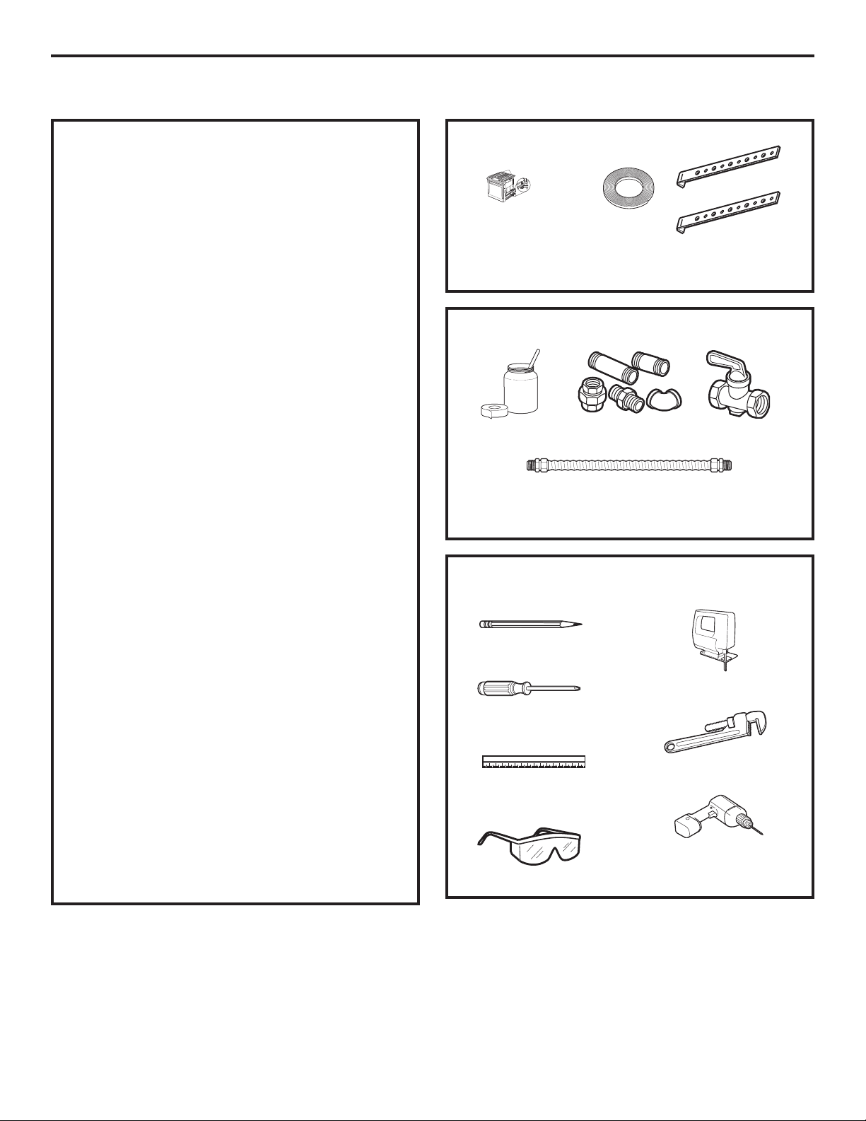
PARTS INCLUDED
2 Screws
Foam Tape
MATERIALS YOU MAY NEED
Joint Sealant
CSA-Approved Flexible Gas Line
3/8s Min. ID, 1/2s NPT Connection,
3-foot Maximum Length (Massachusetts Only)
Pipe Fittings
2 Hold
Down Brackets
Shut-Off Valve
In Canada your cooktop must be wired and fused
to meet the requirements of the Canadian Electrical
Code, CSA C22.1-02.
Be sure the installation of this product in a mobile
home conforms with the Manufactured Home
Construction and Safety Standard, Title 24 CFR,
Part 3280. If this standard does not apply, you
must follow the standard for Manufactured Home
Installations, ANSI A225.1 and Manufactured Home
Installations, Sites and Communities and ANSI/
NFPA 501A or with local codes.
You can get a copy of the Federal Standard by
Writing:
Office of Mobile Home Standards
HUD Building
451 7th Street, S.W.
Washington, D.C. 24010
TOOLS YOU WILL NEED
FOR INSTALLATION
Pencil
Saber Saw
Phillips-Head
Screwdriver
Pipe Wrench
Ruler or Straightedge
1/8s Drill Bit & Electric or
Hand Drill
Safety Glasses
2
Page 3
Installation Instructions
PRE-INSTALLATION CHECKLIST
When preparing cooktop opening, make
A
sure the inside of the cabinet and the
cooktop do not interfere with each other.
(See section on preparing the opening.)
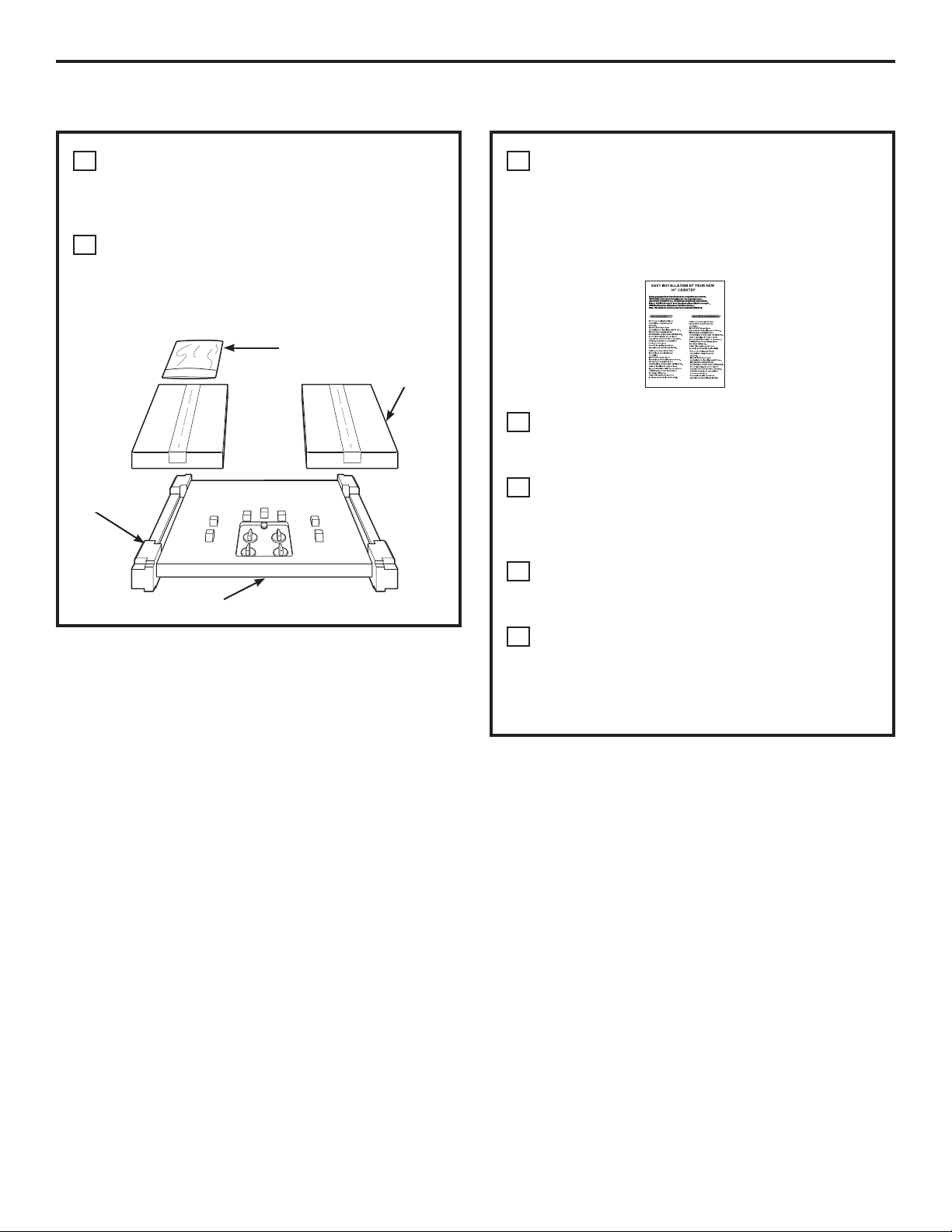
Remove packaging materials, grate boxes,
B
regulator with literature, and literature
package from the cooktop before beginning
installation.
Literature Package
Foam
Packaging
Cooktop
Grate boxes
Remove Installation Instructions from
C
literature pack and read them carefully
before you begin.
Be sure to place all literature, Use and Care,
Installations, etc. in a safe place for future
reference.
Make sure you have all the tools and
D
materials you need before starting the
installation of the cooktop.
Your home must provide the adequate
E
electrical service needed to safely and
properly use your cooktop. (Refer to section
on electrical requirements.)
When installing your cooktop in your home,
F
make sure all local codes and ordinances
are followed exactly as stated.
Make sure the wall coverings, countertop
G
and cabinets around the cooktop can
withstand heat (up to 200°F) generated by
the cooktop.
3
Page 4
Installation Instructions
PREPARING THE OPENING
MAINTAIN THE FOLLOWING
1
MINIMUM CLEARANCE
DIMENSIONS
13s MAX. Depth of unprotected
overhead cabinets
30s MIN. clearance from countertop
to unprotected overhead surface
3-3/4s MIN. clearance from
cutout to side wall on the
left of the unit
NOTE: Allow 7/16”
minimum vertical
clearance from the
cooktop bottom (or 3-5/8”
minimum depth from
the countertop) to any
combustible surfaces,
such as a cabinet drawer.
For island installation, maintain 2-1/2 in. minimum
from cutout to front and back edge of countertop.
Maintain 3 in. minimum from cutout to side edges of
countertop.
6s MIN. clearance from
3 3/4 MIN.
cutout to side wall on the
right of the unit
18s MIN. height
from countertop to
nearest cabinet on
either side of unit
3-5/8s
7/16s
DRAWER
RECOMMENDED GAS SUPPLY
4
LOCATION FROM BACKWALL
1” Min. From Backwall
Recommended
gas supply
location
MAKE SURE WALL COVERINGS,
5
13-1/4s
From Cutout
Center Line
COUNTERTOP AND CABINETS
AROUND COOKTOP CAN
WITHSTAND HEAT (UP TO 200°F)
GENERATED BY COOKTOP
Wall covering,
cabinets and
countertop must
withstand heat
up to 200°F
OVERALL COOKTOP DIMENSIONS
2
21s(21-1/2s Max. for
30s
Cooktop
19-3/8s
CUTOUT DIMENSIONS OF
3
Glass Top models)
3-3/16s
28-1/4s
COUNTERTOP
To ensure accuracy, it is best to make a
template when cutting the opening in the
counter.
28-1/2”
length
of cut
2-1/4” Min. Between
cutout and the wall
behind the cooktop
2-1/2” Min. from front
edge of cutout and front
edge of countertop
19-5/8” width cut
14-1/4s
FOR AMERICANS WITH DISABILITIES
6
ACT (ADA) FORWARD APPROACH
INSTALLATION ONLY:
5”
Allow 5” minimum
depth between the
countertop and an
enclosure.
NOTE: The enclosure must be made of wood
material. Also, an access panel is required for the
electrical outlet , pressure regulator, shut-off valve,
hold-down brackets, and service.
4
Page 5
Installation Instructions
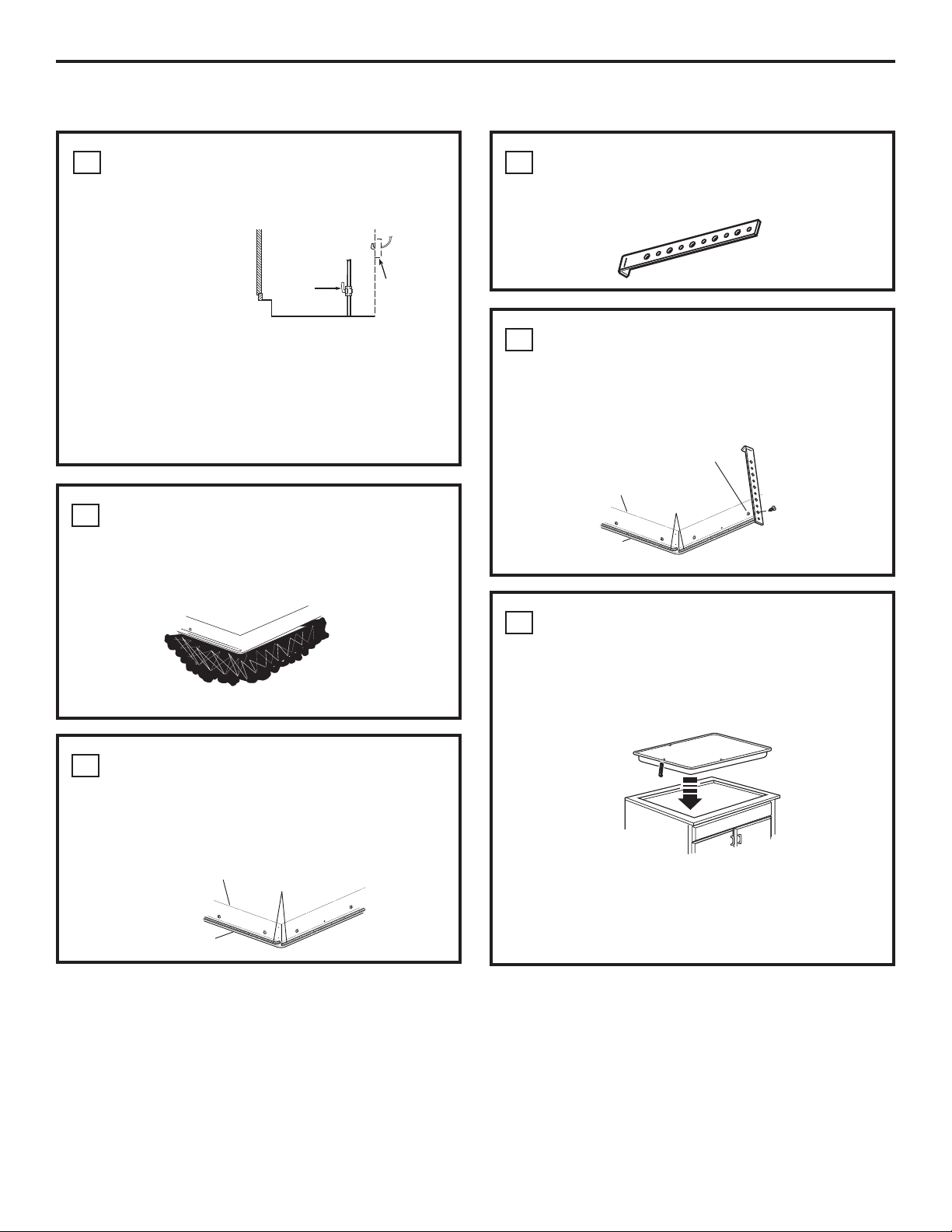
INSTALLING THE COOKTOP UNIT
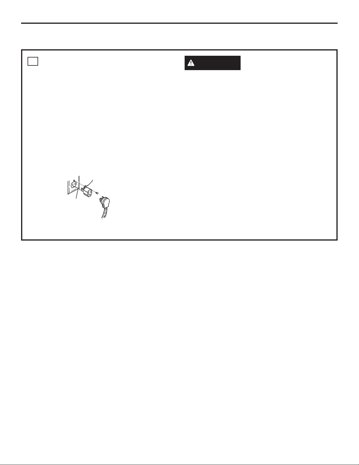
LOCATE ELECTRICAL OUTLET AND
1
GAS SHUT-OFF VALVE BENEATH
CABINET
NEVER REUSE OLD
CONNECTORS WHEN
INSTALLING THIS
UNIT.
Install a manual shut-off valve in the gas line in an
easily accessible location outside the cooktop. Be
sure you know how and where to shut off the gas
supply to the cooktop. Install the electrical outlet
12s below the countertop.
PROTECT SURFACE OF COOKTOP
2
Place a towel or tablecloth onto the countertop.
Lay the cooktop upside down onto the protected
surface.
Bottom of cooktop
Cloth under Cooktop
Shut Off
Valve
Electrical
Outlet 12s
Below
Countertop
LOCATE MOUNTING PARTS
4
Remove the hold-down brackets from the literature
package.
ATTACH BRACKETS TO COOKTOP
5
Remove the screw from the side of the cooktop
and screw the hold-down bracket to the side of the
cooktop unit. Repeat for opposite side of cooktop.
Pre-drilled
Bottom of
Cooktop
Cooktop
Glass
INSERT COOKTOP INTO CUTOUT
6
Insert the cooktop centered into the cutout opening.
Make sure the front edge of the countertop is
parallel to the cooktop. Make final check that all
required clearances are met.
hole
Foam Tapes
ATTACH FOAM TAPE
3
(glass maintop models only)
Apply the foam tape around the outer edge
of the glass. Do not overlap the foam strips.
Bottom of Cooktop
Cooktop Glass
Foam Tapes
Cooktop
Once the unit is in place, screw the hold-down
bracket into the cabinet sides to secure the unit
into place.
5
Page 6
Installation Instructions
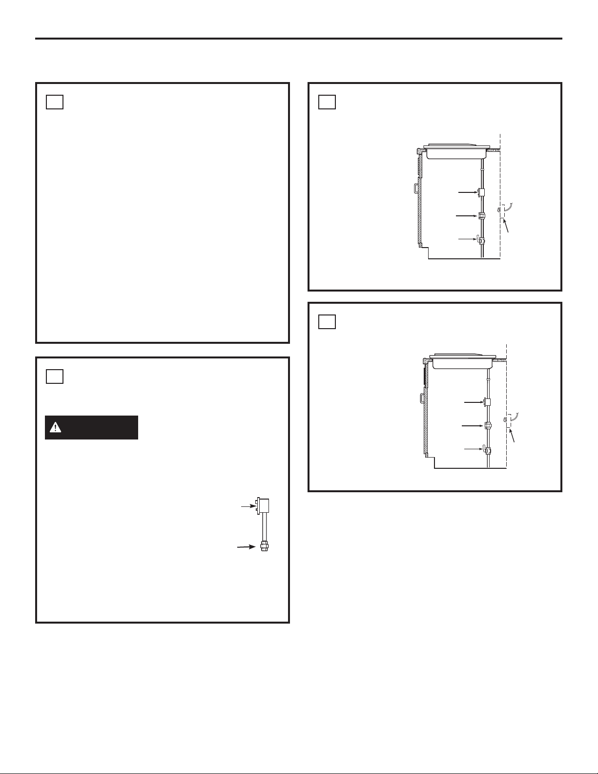
,167$//$7,21³*$6&211(&7,216
PROVIDE ADEQUATE GAS SUPPLY
1
This cooktop is designed to operate on natural
gas at 4s of water column manifold pressure and
7s of water column (W.C.) supply pressure. It is
shipped from the factory set for natural gas. The
convertible pressure regulator supplied with the
unit must be connected in series with the manifold
of the cooktop and must remain in series with the
supply line regardless of whether natural or L.P.
gas is being used. FOR PROPER OPERATION, THE
MAXIMUM INLET PRESSURE TO THE REGULATOR
MUST BE NO MORE THAN 14s OF WATER COLUMN
PRESSURE. For checking the regulator, the inlet
pressure must be at least 1s W.C.. (or 3.4 KPA)
greater than the regulator output setting. If
the regulator is set for 4s W.C. of water column
pressure, the inlet pressure must be at least 5sW.C.
If the regulator is set for 10sW.C., the inlet pressure
must be at least 11sW.C.. The gas supply line to
the cooktop should be 1/2s or 3/4s pipe.
INSTALL REGULATOR
2
NEVER REUSE OLD CONNECTORS WHEN
INSTALLING THIS COOKTOP.
INSTALL REGULATOR ONTO
3
BURNER BOX BOTTOM
Screw the regulator
onto the burner
box bottom pipe
connection. Make
sure the top of
the regulator is
Pressure
Regulator
facing towards the
cabinet front, easily
accessible through
the cabinet doors.
COMPLETE CONNECTION WITH A
4
Coupling
Shut-Off
Valve
COUPLING
Complete the
connection between
the regulator, pipe
coupling, and
the shut-off valve.
Pressure
Regulator
Electrical
Outlet 12s
Below
Countertop
WARNING
Never reuse old flexible
connectors. The use of old flexible connectors
can cause gas leaks and personal injury. Always
use new flexible connectors when installing a gas
appliance.
Pressure
Screw a section of pipe onto
Regulator
the inlet end of the pressure
regulator and install the
coupling.
Coupling
To reduce the likelihood of gas leaks, apply teflon
tape or a thread compound approved for use
with Propane (LP) or Natural gases to all threaded
connections.
Coupling
Shut-Off
Valve
Electrical
Outlet 12s
Below
Countertop
6
Page 7
Installation Instructions
CHECK FOR LEAKS
5
Before testing for leaks, make sure all burner knobs
are in the OFF position.
After connecting the cooktop to gas, check system
for leaks with a manometer. If a manometer is not
available, turn the gas supply on to the cooktop
and use a liquid leak detector at all joints and
connections to check for leaks.
Tighten all connections if necessary to prevent gas
leakage in the cooktop or supply line.
DO NOT USE OPEN FLAME TO CHECK FOR
LEAKS!
Disconnect the cooktop and its individual shut-off
valve from the gas supply piping system during any
pressure testing of that system at test pressures
greater than 1/2 psig (3.5 kPa).
Isolate the cooktop from the gas supply piping
system by closing its individual shut-off valve
during any pressure testing of the gas supply
system at test pressures equal to or less than 1/2
psig (3.5 kPa).
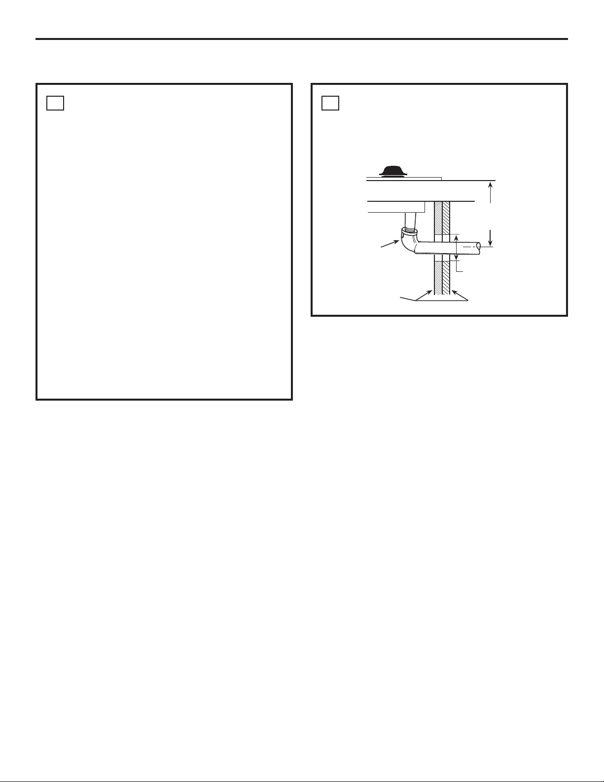
INSTALLATION OVER BUILT-IN
6
OVEN
See built-in oven installation for complete
installation instructions.
5s To Center of
2s Dia. Hole From
Countertop
90° Elbow
2s Dia. Hole
(20 7/8s from front
of Countertop to
Cabinet Sides
Hole Center)
7
Page 8
Installation Instructions
,167$//$7,21³(/(&75,&$/&211(&7,216
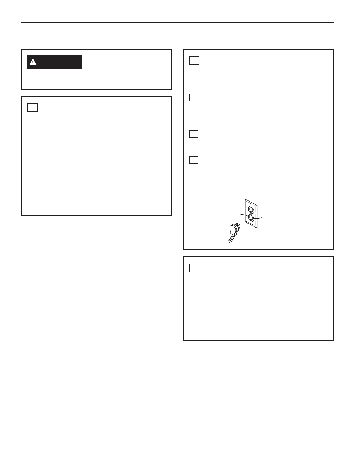
ELECTRICAL SUPPLY AND OUTLET
2
WARNING
at the main circuit breaker or fuse box before
installing.
EXTENSION CORDS
1
Because of potential safety hazards under certain
conditions, we strongly recommend against the
use of an extension cord. However, if you still
elect to use an extension cord, it is absolutely
necessary that it be a UL listed 3-wire grounding
type appliance extension cord and that the
current carrying rating of the cord in amperes be
equivalent to or greater than the branch circuit
rating. Such extension cords are obtainable
through your local appliance dealer.
Disconnect all electrical power
IMPORTANT: (Please read carefully) FOR
PERSONAL SAFETY, THIS APPLIANCE MUST BE
PROPERLY GROUNDED.
An adequate electrical supply and outlet must
be used to operate the electrical parts of your
cooktop.
The power cord of this appliance is equipped
A
with a 3-prong (grounding) plug which must
be used with a properly grounded 3-hole
outlet with a standard 120 Volt, 60 cycle AC
household current.
B
If you do not have a 3-hole grounded outlet,
have a qualified electrician change your old
one.
A grounding adaptor will be needed to convert
C
the old one until the outlet can be replaced.
This method is only temporary, and a qualified
electrician should test it to be sure it meets
requirements.
N
Insure proper
ground and
L
firm connection
before use
TWO-PRONG WALL RECEPTACLE
3
Where a standard 2-prong wall receptacle is
encountered, it is the personal responsibility and
obligation of the customer to have it replaced with
a properly grounded 3-prong wall receptacle.
Do not under any circumstances cut or remove
grounding prong from the cooktop cord. Failure
to provide proper polarization may create a
hazardous condition.
8
Page 9
Installation Instructions
USAGE SITUATIONS WHERE
4
APPLIANCE POWER CORD
WILL BE DISCONNECTED
INFREQUENTLY
For 15 amp circuit only. Do not use an adaptor
on a 20 amp circuit. Where local codes permit, a
TEMPORARY CONNECTION may be made to a properly
grounded 2-prong wall receptacle by the use of a
UL-listed adaptor available at most hardware stores.
The larger slot in the adaptor must be aligned with
the large slot in the wall receptacle to provide proper
polarity in the connection of the power cord.
CAUTION
terminal to the wall receptacle cover screw does not
ground the appliance unless the screw is metal, and
not insulated, and the wall receptacle is grounded
through the house wiring. The customer should have
the circuit checked by a qualified electrician to make
sure the receptacle is properly grounded.
When disconnecting the power cord from the
adaptor, always hold the adaptor with one hand. If
this is not done, the adaptor ground terminal is very
likely to break with repeated use. Should this happen,
DO NOT USE the appliance until a proper ground has
again been established.
Attaching the adaptor ground
Ensure proper ground and firm
connection before use
Align large
prongs/slots
Temporary Method
(Adaptor plugs not permitted in Canada)
Usage situation where appliance power cord will be
disconnected frequently.
Do not use an adaptor plug in these situations
because disconnection of the power cord places
undue strain on the adaptor and leads to eventual
failure of the adaptor ground terminal. The customer
should have the 2-prong receptacle replaced with
a 3-prong (grounding) receptacle by a qualified
electrician before using the appliance.
9
Page 10
Installation Instructions
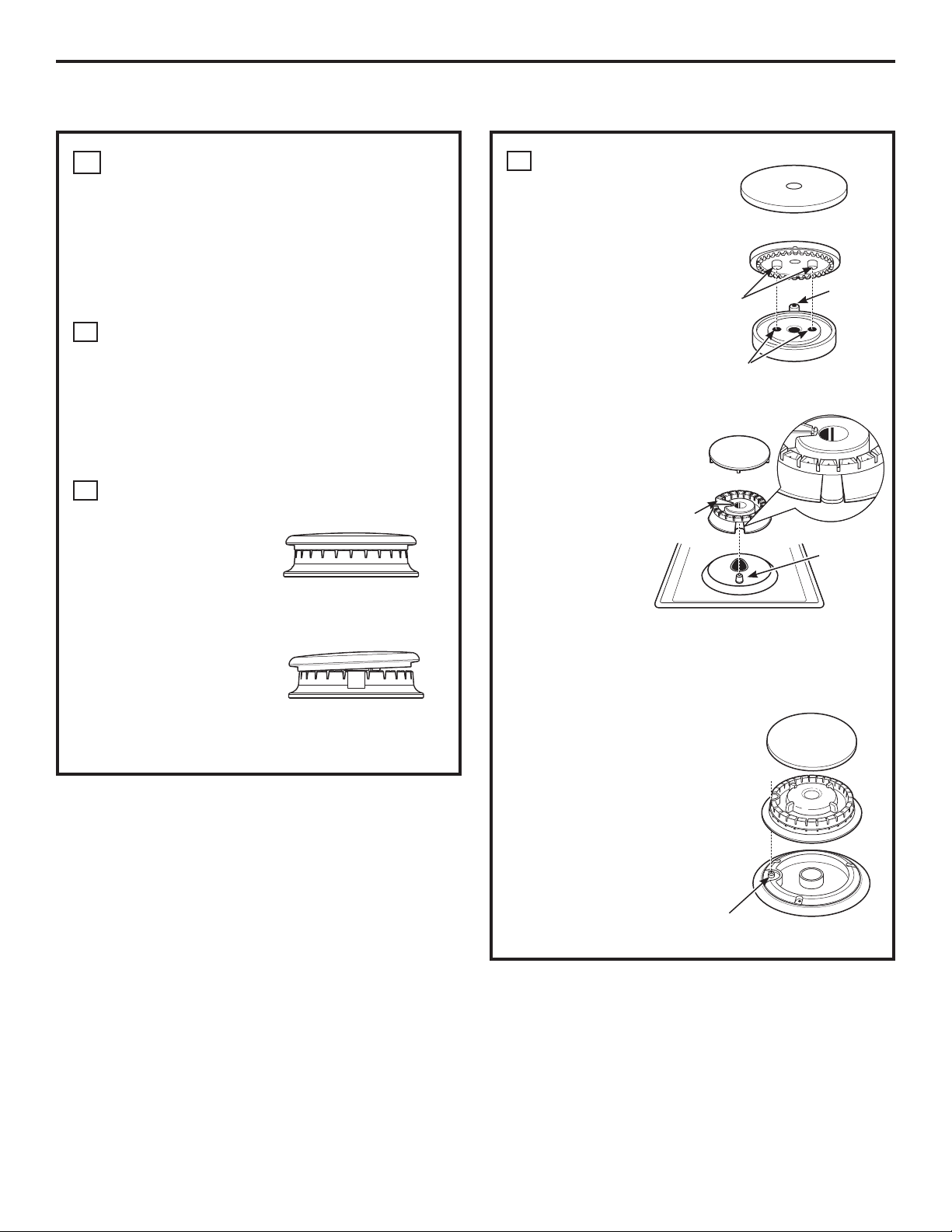
COOKTOP BURNERS
ASSEMBLING THE COOKTOP
1
BURNERS
The electrode of the spark igniter is exposed. Be
careful not to push any cooktop controls while the
top of the burner is removed.
Do not remove the top or touch the electrode
of any burner while another burner is turned on.
Electrical shock might result.
Replace the burner head onto the burner
A
base, making sure that the head is properly
oriented over the burner base and the
electrode. Make sure to place the correct
burner head on the correct burner base and
that the burner head sits level on the burner
base. The burner heads are not
interchangeable.
Place the burner
B
caps on the burner
heads, making sure
to place the correct
burner cap on the
correct burner
head. The burner
caps are not
interchangeable.
Make sure that the
burner caps are
properly seated on
the burner heads.
Burner cap properly seated
Burner cap not properly seated
Make sure the pins in
C
the burner heads
match the burner
base indentations
and that they are
properly seated in
them by rotating the
heads until they are
level.
Make sure the slot in
the burner head
is positioned
over the
electrode.
The burner cap
has three to
four pins.
When
Stability
chamber
replacing the
cap, make
sure none of
the pins sits
in the stability
chamber.
Make sure
the hole
in the burner
head assembly is
positioned over the
electrode and that
the burner head is
fully inserted inside
the burner base. A
small gap between
the base and head is
normal.
Locator
pins
Pin
indentations
Burner cap
Burner head
Burner base
Burner head
assembly
Burner cap
Burner head
Electrode
Burner
base
Electrode
Burner cap
10
Electrode
Burner
base
Page 11

Installation Instructions
CHECK IGNITERS
2
Operation of the electric igniters should be checked
after the cooktop and supply line have been
carefully checked for leaks and the cooktop has
been connected to the electrical power.
On models so equipped, check to be sure the
cooktop is in the UNLOCKED position.
Push and turn a burner valve to the LITE
A
position. All spark igniters will make a series of
sparks (ticking sounds), but only the burner
turned to LITE will light.
• The burner should light when gas is
available to the burner.
• Once the burner lights, it should be turned
out of the LITE position.
Try each valve separately until all burners
B
have been checked.
BURNER IGNITION
3
&RRNWRS6SDUN,JQLWLRQ³:KHQ\RXWXUQWKH
cooktop knob to LITE, the spark igniter makes a
series of electric sparks (ticking sounds) which light
the burner. During a power failure, the burners will
not light automatically. In an emergency, a cooktop
burner may be lit with a match by following the
steps below.
WARNING
match is dangerous. You should match light the
cooktop burners only in an emergency.
Lighting gas burners with a
THE BURNER FLAMES
4
Turn each burner on. Flames should be blue in color
with no trace of yellow. The burner flames should
not flutter or blow away from the burner. The flame
should be no less than 1/4s on the lowest setting
and no greater than 1-1/2s on highest setting.
WARNING
flame, please use caution. Burns could result.
1/4s to
1-1/2s
Burners should be checked frequently
BURNER GRATES
5
The cooktop grates are designed for specific
positions. For maximum stability, these grates
should only be used in their proper position: they
should not be interchanged. For your convenience,
the undersides of the left and right grates are
marked “OUTSIDE” and “INSIDE”. Make sure that the
side marked “OUTSIDE” is on the outer edge of your
cooktop.
If you attempt to measure the
Cooktop Burner
On models so equipped, check to be sure the
cooktop is in the UNLOCKED position.
Light a match and hold the flame near the
A
burner you want to light. Wooden matches
work best.
Push in and turn the control knob slowly. Be
B
sure you are turning the correct knob for the
burner you are lighting.
NOTE: If the burner does not light within five seconds,
turn the knob off and wait one minute before trying
again.
11
“OUTSIDE”
edge
“INSIDE”
edges
“OUTSIDE”
edge
Page 12

Installation Instructions
OPERATION CHECKLIST
Make sure all controls are left in the OFF
A
position. Check to be sure the cooktop is in the
UNLOCKED position (on models so equipped).
Make sure the flow of air to and from the
B
cooktop is unobstructed.
The serial plate for your cooktop is located on
C
the bottom of the burner box. In addition to the
model and serial numbers, it tells you the ratings
of the burners and the type of fuel and pressure
the cooktop was adjusted for when it left the
factory.
When ordering parts, always include the serial
D
number, model number and a code letter to
ensure proper replacement parts.
Recheck Steps:
E
Double check to make sure everything in this
guide has been completed. Rechecking steps
will ensure safe use of the cooktop.
12
Page 13

Installation Instructions
MAKING THE PROPANE (LP) CONVERSION
IF SOLD OUTSIDE THE U.S. AND CANADA:
WARNING
with Liquefied Petroleum (LP) gas containing greater
than 10% butane, you must purchase a butane
conversion kit. To order, please call 1.888.664.8403 or
1.787.276.4051.
JGP333 &
1
SAFETY INFORMATION YOU SHOULD KNOW
The pressure regulator and burner orifices are set for
natural gas. To use Propane (LP) gas, the regulator
and burner orifices must be converted. The Propane
(LP) orifice spuds for the cooktop burners are attached
to the regulator along with separate Propane (LP)
conversion instructions.
If you wish to use this product
Model Butane Kit #
JGP940 WB28T10228
PGP943
JGP329 WB28T10234
WB28T10283
TOOLS YOU WILL NEED
FOR PROPANE (LP) CONVERSION
Phillips-Head
Screwdriver
Pliers
Safety Glasses
CAUTION
factory, is set for use with natural gas. If you wish to
use your cooktop with Propane (LP) gas, you must first
replace the orifices and convert the pressure regulator.
The cooktop, as shipped from the
7mm Nutdriver
No. 15 Torx-Head
Driver
Small Flat-Head
Screwdriver (4mm or
5/32s tip size, 60mm or
2-3/8” long)
WARNING
be installed by a qualified service agency in
accordance with the manufacturer’s instructions
and all applicable codes and requirements of the
authority having jurisdiction. If the information
in these instructions is not followed exactly, a
fire, explosion or production of carbon monoxide
may result causing property damage, personal
injury or loss of life. The qualified service agency
is responsible for the proper installation of this kit.
The installation is not proper and complete until
the operation of the converted appliance is checked
as specified in the manufacturer’s instructions
supplied with the kit.
This conversion kit shall
CAUTION
be made before turning on the burner. Failure to do
so could result in serious injury. Be sure pressure
regulator has been converted as described in Step 2.
CAUTION
conversion, shut off the gas supply to the appliance
prior to disconnecting the electrical power.
The following adjustments must
Before proceeding with the
13
Page 14

Installation Instructions
MAKING THE PROPANE (LP) CONVERSION (CONT.)
ADJUST YOUR COOKTOP FOR USE
2
WITH PROPANE (LP) GAS
Disconnect all electrical power, at the main
A
circuit breaker or fuse box.
Shut off the gas supply to the cooktop
B
by closing the manual shut-off valve.
Adjust the pressure regulator, by the following
C
instructions:
• Unscrew the cap.
• Carefully look at the spring retainer to locate
the NAT or Propane (LP) position.
Gasket
NAT
LP
NAT
Spring
Retainer
LP
L.P./Propane
Position
NAT
LP
NAT
NAT.
Position
LP
Cap
CHANGE COOKTOP BURNER
3
ORIFICES (CONT.)
Remove the spark
B
igniters from the burner
base (if required to
access the orifices).
Using a No. 15 “Torx”
head driver bit, remove
the screws holding the
burner base in position.
Using a 7mm nut driver,
C
remove the top burner
orifices. These may be
accessed through the
hole in the cooktop.
Spark igniter
Burner
base
Burner cap
Burner
head
Burner
base
18,000 BTU Burner
(on some models)
Burner
cap
Burner
head
Pressure Regulator
• Turn the spring retainer over by rotating it
90 deg., pull it from the cap, turn the spring
retainer over so that LP is showing, insert it
back into the cap, and then rotate it 90 deg.
into position.
• Screw the cap back onto the regulator and
tighten.
CHANGE COOKTOP BURNER
3
ORIFICES
Remove the top grates,
A
burner caps, and burner
heads.
Remove This
Assembly
On most burners,
the orifices have a
spring-loaded retaining
ring around the hex
head to hold the orifice
in the nut driver during
installation and removal.
A slight amount of force
is required to push the nut
driver down over the ring.
NOTE: For orifices that
do not have a springloaded retaining ring, use
pliers to hold the orifice
in position during initial
thread engagement or final
removal to avoid dropping
the orifice in the cooktop.
Then use the nut driver to
tighten or loosen.
Spark igniter
Retainer
Ring
Orifice Spud Located
Through This Opening
14
Page 15

Installation Instructions
CHANGE COOKTOP BURNER
3
ORIFICES (CONT.)
Locate the Propane (LP) orifices attached to
D
the regulator along with separate Propane
(LP) conversion instructions. They will have a
digit for size, and a letter for type of gas, on
the top or side. (Important: Save the orifices
removed from the appliance for future use.)
Each orifice will show a series of engraved
marks, (I, II, III, X or none), located on the top.
These marks denote the precise location of each
orifice to the cooktop burner.
I II III
15,000 BTU/HR Burner
The 15,000 BTU/HR burner has two orifices with
markings located in the sides only. (See rating
plate on bottom of appliance).
(on some models)
X
JGP329
86 L
86 L
JGP333 & PGP943
92 L
86 L
JGP940
63 L
92 L
63 L
See
Below
Main: 99 HXL
Simmer: 34 SL
NOTE: The main orifice is located low in the center
of the burner while the simmer orifice is located
higher behind the center of the burner.
Simmer
orifice
Main orifice
84 L
91 L
Install the Propane (LP) orifices in their precise
E
74 L
104L
X
locations as noted in the illustrations above.
Return the natural gas orifices to the bracket
F
and reattach the bracket and the instruction
sheet to the pressure regulator using the
screw removed previously.
Replace the burner bases, heads, caps and
G
top grates. (NOTE: When re-attaching the
burner bases to glass top units, tighten screws
to a maximum of 10 in.-lbs torque.)
15
Page 16

Installation Instructions
MAKING THE PROPANE (LP) CONVERSION (CONT.)
Make the adjustment by slowly turning the
ADJUST BURNER FLAMES
4
Turn all burners full on and check the flames.
A
They should be blue in color with some yellow
tipping at the ends of the flame. Foreign
particles in the gas line may cause an orange
flame at first, but this will soon disappear.
NOTE: For the 15,000 BTU/HR burner (on some
models) the cooktop burner knob should be
turned to the setting before the lowest setting.
This will ensure that the entire burner is
operating.
Turn the cooktop burner knob to the lowest
B
setting while observing the flame.
Adjust the low flame setting using the valve bypass
screw as follows:
Low-setting adjustments must be made with two
other burners in operation on a medium setting.
This prevents the low flame from being set too low,
resulting in the flame being extinguished when
other burners are turned on.
To adjust the flame, remove the knobs. Insert
C
a screwdriver through the access hole in valve
switch. Engage
adjustment screw in
valve. Refer to the
illustration below that
matches the adjustment
screw location for your
model.
• If the flames were too
small or fluttered, open
the valve more than
the original setting.
• If the flames blew
away from the burner,
close the valve more
than the original
setting.
15K burner
only
D
screw until flame appearance is correct.
Note: Some models may contain a silicone shield
which covers the valve switch and access hole. A
flashlight may be required to locate the access hole. To
access the valve adjusting screw, push the screwdriver
through this shield. After adjustment, reseat the
shield around the switch hub with your fingers, after
withdrawing the screwdriver.
Reseat silicone shield
CORRECT INCORRECT
Testing Flame Stability:
E
Test 1 – Turn the knob from “HI” to the lowest
setting quickly. If the flame goes out
at the lowest setting, increase the
flame size and test again.
Test 2 – With the burner on the lowest setting,
open and close the cabinet door
under the cooktop. If the flame is
extinguished by the air currents
created by the door movement,
increase the flame height and test
again.
Flame Recheck:
F
After the adjustment is made, turn all burners off.
Ignite each burner individually. Observe the flame
at the “HI” position. Rotate the valve to the lowest
setting and be sure that the flame size decreases
as the valve is rotated counterclockwise.
TO CONVERT THE COOKTOP BACK TO NATURAL
GAS, REVERSE THE STEPS UNDER MAKING THE
PROPANE (LP) CONVERSION.
Once the conversion is complete and checked ok,
fill out the Propane (LP) sticker and include your
name, organization and date conversion was
made. Apply the sticker near the cooktop gas
inlet opening to alert others in the future that this
appliance has been converted to Propane (LP) gas.
If converting back to natural gas from Propane
(LP), please remove the sticker so others know the
appliance is set to use natural gas.
16
Page 17

Instructions Table de cuisson scellée
d’installation
au gaz de 76 cm (30”)
JGP329, JGP333, JGP940, PGP943
Questions? Appelez le Centre de réponse 1.800.561.3344 ou visitez notre site
Web à l’adresse : www.electromenagersge.ca
AVANT DE COMMENCER
Avant de commencer, lisez attentivement la totalité
de ces instructions.
•
IMPORTANT ³ Conservez ces
instructions pour votre inspecteur local.
•
IMPORTANT ³ Respectez toutes les
ordonnances et les codes locaux.
•
Note à l’installateur – Assurez-vous de laissez ces
instructions au consommateur.
• Note au consommateur – Conservez ces
instructions pour référence future.
• La garantie ne couvre aucune panne due
à une mauvaise installation.
AVERTISSEMENT
Cet appareil doit être bien mis à la terre.
•
IMPORTANT ³ Vous devez vérifier que
cet appareil n’ait pas de fuite conformément aux
instructions du fabricant.
• L’installateur est responsable d’une bonne
installation et la garantie ne couvre aucune
panne due à une mauvaise installation.
POUR VOTRE SÉCURITÉ
AVERTISSEMENT
Si les instructions de ce manuel ne sont pas
observées rigoureusement, vous risquez
d’occasionner un incendie, une explosion ou une
fuite de gaz, qui peuvent provoquer des dommages
matériels, des blessures corporelles ou la mort.
Ne conservez pas ou n’utilisez jamais d’essence
ou d’autres liquides ou vapeurs inflammables à
proximité de cet appareil ou de tout autre appareil
ménager!
Ne pas installer ce produit si l’on utilise une hotte à
rideau d’air ou une hotte de cuisinière soufflant l’air
au-dessus de la surface de cuisson. Le débit d’air
peut nuire au fonctionnement des brûleurs à gaz et
représente un risque d’incendie ou d’explosion.
CI QUE VOUS DEVEZ FAIRE SI
VOUS SENTEZ LE GAZ :
• N’essayez jamais d’allumer un appareil
électroménager. Ne touchez à aucun
commutateur d’électricité, n’utilisez jamais un
téléphone dans votre bâtiment.
• Appelez immédiatement votre fournisseur de
gaz à l’aide du téléphone d’un voisin. Suivez les
instructions de votre fournisseur de gaz.
AVERTISSEMENT
courant électrique au niveau du disjoncteur de la
maison ou de la boîte à fusibles avant d’installer.
31-10860-3 (05-17 GEA)
Débranchez tout
• Si vous ne pouvez pas entrer en contact avec
votre fournisseur de gaz, appelez les pompiers.
L’installation et le service de votre table de cuisson
doivent être faits par un installateur qualifié, un
technicien de service ou votre fournisseur de gaz.
1
Page 18

Instructions d’installation
INSTRUCTIONS IMPORTANTES DE SÉCURITÉ
La conception de votre table de cuisson a été
approuvé par l’ACNOR International. Vous trouverez
des précautions à prendre en matière de sécurité
dans votre Guide d’utilisation et de soins. Lisez-les
attentivement.
• L’installation de votre table de cuisson
doit se conformer aux codes locaux ou, en
l’absence de codes locaux, au National Gas and
Propane Installation Code, CSA B149.1 - Dernière
édition.
• Assurez-vous que votre table de cuisson soit
bien installée par un installateur qualifié ou un
technicien de service.
• Pour éliminer tout mouvement corporel
au dessus des brûleurs de votre table de cuisson,
évitez de placer des armoires de cuisine au
dessus des brûleurs.
• N’installez jamais votre appareil près d’une porte
d’entrée ou dans un emplacement où un courant
d’air peut gêner son usage.
PIÈCES COMPRISES
2 vis
Bandes de mousse (Pour
les modèles à surface en
verre seulement)
2 Supports de fixation
MATÉRIAUX DONT VOUS POUVEZ
AVOIR BESOIN
Agent de scellement
de tuyau
Raccord flexible de gaz approuvé par l’ACNOR
Raccords de tuyaux
DI min 3/8’’, Jonction NPT 1/2
Robinet d’alimentation
de gaz
BESOINS D’ÉLECTRICITÉ
Cet appareil ménager doit être livré avec le bon
voltage et la bonne fréquence et branché à son
propre circuit de dérivation bien mis à la terre,
protégé par un disjoncteur ou un fusible qui ont
l’ampérage noté sur la plaque minéralogique de
votre appareil.
Nous vous recommandons de faire brancher le
câblage électrique et la fiche de votre cuisinière
par un électricien qualifié. Après l’installation,
demandez à l’électricien de vous montrer
l’emplacement de votre coupe-circuit principal.
Demandez à votre entreprise de services publics les
codes électriques en vigueur dans votre région. En
ne câblant pas votre cuisinière conformément aux
codes en vigueur, vous provoquez une situation
dangereuse. En l’absence de codes, vous devez
câbler et isoler votre cuisinière conformément
aux exigences du Canadian Electrical Code, CSA
C22.1-02.
OUTILS DONT VOUS AUREZ BESOINS
Crayon
Scie sauteuse
Tournevis Phillips
Règle ordinaire ou de
vérification
Perceuse à main ou électrique
Lunettes de sécurité
Clé à tuyau
et foret de 1/8po
2
Page 19

Instructions d’installation
LISTE DE VÉRIFICATION AVANT INSTALLATION
Pour préparer l’ouverture de la surface de
A
cuisson, vous devez vous assurer que
l’intérieur de l’armoire ne touche pas la table
de cuisson (consultez la section sur la
préparation de l’ouverture).
Enlevez les matériaux d’emballage, les
B
boîtes de grille, le régulateur avec sa
documentation et la documentation de
votre table de cuisson avant de commencer
à l’installer.
Documentation
Emballage
en mousse
Table de
cuisson
Boîtes de
grille
Enlevez les instructions d’installation de la
C
trousse de documentation et lisez-les
soigneusement avant de commencer.
Assurez-vous de bien ranger toute la
documentation, le manuel d’utilisation et
d’entretien, etc. dans un endroit sûr pour
référence future.
Assurez-vous d’avoir tous les outils et tous
D
les matéraux nécessaires avant de
commencer à installer votre table de
cuisson.
Votre maison doit être alimentée en courant
E
électrique adéquat pour vous permettre de
bien utiliser en toute sécurité votre table de
cuisson. (Consultez la section sur les besoins
d’électricité.)
Pour installer votre table de cuisson dans
F
votre maison, assurez-vous de vous
conformer scrupuleusement à tous les
codes et à toutes les ordonnances locales.
Assurez-vous que les revêtements de mur, le
G
comptoir et les armoires autour de la table
de cuisson puissent supporter la chaleur
[pouvant atteindre 93°C (200°F)] produite
par la table de cuisson.
3
Page 20

Instructions d’installation
PRÉPARATION DE L’OUVERTURE
VOUS DEVEZ RESPECTER LES
1
DÉGAGEMENTS MINIMAUX
SUIVANT
Profondeur max
de 33 cm (13s) des
armoires en surplomb
non protégées
Dégagement min. de 76 cm (30s) du
comptoir à la surface en non surplomb
non protégées
Dégagement min
de 10 cm (3-3/4s) du
découpage au mur de côté
droite de l’appareil
REMARQUE : Laissez un
9,2 cm
3-5/8s)
(
dégagement vertical
minimum de 1,1 cm (7/16
po) entre le dessus de la
table de cuisson (ou une
profondeur minimum de
9,2 cm (3-5/8 po) et toute
surface combustible, par
exemple un tiroir d’armoire.
Pour une installation en îlot, maintenir
une distance minimum de 6,3 cm (2 ½ po) entre le bord
et le dos du comptoir. Garder un espace de 7,6 cm (3 po)
minimum sur les côtés du comptoir.
Dégagement min. de 15
cm (6s) découpage au
3 3/4 MIN.
mur de côté à droite de
l’appareil
Hauteur min de
45 cm (18s) du
comptoir
à l’armoire la
plus proche de
chaque côté de
l’appareil
7/16ȩ)
1,1 cm (
TIROIR
DRAWER
EMPLACEMENT RECOMMANDÉ DE
4
L’ALIMENTATION DE GAZ À PARTIR
DU MUR ARRIÈRE
2.5 cm (1s) min. du mur arrière
Emplacement
recommandé de
l’alimentation
de gaz
ASSUREZ-VOUS QUE
5
33.7 cm
(13-1/4s) Du
découpage
á la ligne du
centre
LES REVÊTEMENTS MUR, LE
COMPTOIR ET LES ARMOIRES
AUTOUR DE LA TABLE DE CUISSON
PUISSENT SUPPORTER LA CHALEUR
(POUVANT ATTEINDRE 93°C [200°F])
Les revêtements de
mur, les armoires et
le comptoir doivent
pouvoir supporter
une chaleru pouvant
atteindre 93°C (200°F)
DIMENSIONS DU DÉCOUPAGE DE
2
LA TABLE DE CUISSON
53 cm (21s)(54,6 cm [21-1/2s]
76 cm (30s)
Table de cuisson
49 cm (19-3/8s)
DIMENSIONS TOTALES DE
3
max. pour table de cuisson en
8,1 cm (3-3/16s)
72 cm (28-1/4s)
LA TABLE DE CUISSON
Pour assurer la justesse du découpage,
il vaut mieux faire un gabarit pour couper
l’ouverture dans le comptoir.
72,4 cm (28-1/2 po)
longueur du découpage
Distance min de 5,7
cm (2-1/4s)
de découpage au
mur derrière la table
de cuisson
6,4 cm (2-1/2s) Distance
min. de l’arête avant du
découpagede l’arrête avant de
la table de cuisson
Largeur du découpage
49,8 cm (19-5/8s)
36,2 cm
(14-1/4s)
verre)
INSTALLATION POUR PERSONNE
6
HANDICAPÉE SEULEMENT (É.-U.)
DISABILITIES ACT FORWARD
APPROACH) :
Laissez une
profondeur
minimum de 12,7
cm (5 po) entre la
table de cuisson et
une enceinte.
REMARQUE : L’enceinte doit être
construite en bois. Aussi, un panneau
d’accès est nécessaire pour la prise
électrique, le régulateur de pression, le
robinet de sectionnement , les supports de
retenue et l’entretien ou les réparations.
12,7 cm (5”)
4
Page 21

Instructions d’installation
INSTALLATION LA UNITÉ DE LA TABLE DE CUISSON
PLACEZ LA PRISE
1
D’ALIMENTATION
ÉLECTRIQUE ET LE ROBINET
D’ALIMENTATION DE GAZ
AU-DESSOUS DE L’ARMOIRE
N’UTILISEZ JAMAIS DES
RACCORDS USAGÉS
POUR INSTALLER CET
APPAREIL.
Montez le robinet d’alimentation manuel sur le
tuyau de gaz à un emplacement facile à atteindre
en dehors de la table de cuisson. Assurez-vous de
savoir où et comment couper l’alimentation de gaz
à la table de cuisson. Montez la prise électrique
30 cm (12s) au-dessous du comptoir.
PROTÉGEZ LA SURFACE DE LA
2
Robinet
d’alimentation
Prise électrique
30 cm (12s)
sous le comptoir
TABLE DE CUISSON
Placez une serviette ou un torchon sur le comptoir.
Posez la table de cuisson à l’envers sur la surface
protégée.
Envers de la table de cuisson
Linge sous la table de cuisson
TROUVEZ LES PIÈCES DE
4
MONTAGE
Retirez les supports de fixation de la trousse de
documentation.
FIXEZ LES SUPPORTS DE FIXATION
5
À LA TABLE DE CUISSON
Enlevez la vis d’un côté de la table de cuisson,
vissez un support de fixation à un côté de la table
de cuisson. Répétez la même opération de l’autre
côté de la table de cuisson.
Support de
Bas de la table de
cuisson
Verre de la table
de cussion
INSÉREZ LA TABLE DE CUISSON
6
fixation
Bandes de
mousse
DANS L’OUVERTURE DÉCOUPÉE
Insérez la table de cuisson centrée dans l’ouverture
découpée. Assurez-vous que l’arrête de devant
du comptoir soit bien parallèle à l’extrémité de la
surface de cuisson. Faites une vérification finale
pour vous assurer de bien respecter tous les
dégagements.
ATTACHEZ LA BANDE DE MOUSSE
3
(modèles de la table de verre seulement)
Appliquez la bande de mousse autour du bord
extérieur du verre. Ne superposez pas les bandes
de mousse.
Bas de la table de
cuisson
Verre de la table
de cuisson
Bandes de mousse
Table de cuisson
Une fois la table de cuisson en place, vissez les
supports de fixation aux côtés de l’armoire pour
tenir la table de cuisson bien en place.
5
Page 22

Instructions d’installation
INSTALLATION³%5$1&+(0(17'8*$=
FOURNISSEZ UN BON
1
APPROVISIONNEMENT EN GAZ
Cette table de cuisson est conçue pour fonctionner au
gaz naturel à une pression de tubulure d’admission
de 4 po. de colonne d’eau et à une pression
d’approvisionnement de 7 po. de colonne d’eau. Elle
est expédiée de l’usine réglée pour le gaz naturel.
Le régulateur de pression convertible fourni avec
l’appareil doit être branché en série à la tubulure
d’admission de la table de cuisson et doit rester
branché sur la ligne d’approvisionnement qu’il
s’agisse de gaz naturel ou de gaz propane (LP). POUR
OBTENIR UN BON FONCTIONNEMENT, LA PRESSION
MAXIMALE D’ENTRÉE AU RÉGULATEUR NE DOIT PAS
ÊTRE SUPÉRIEURE À 14 po. DE COLONNE D’EAU. Pour
vérifier le régulateur, la pression d’entrée doit être
au moins de 1 po. de colonne d’eau (ou 3,4 KPA) plus
grande que celle de réglage de sortie du régulateur.
Si le régulateur est réglé à une pression de 4 po. de
colonne d’eau, la pression d’entrée doit être au moins
égale à 5 po.. Si le régulateur est réglé à une pression
de 10 po., la pression d’entrée doit être au moins
égale à 11 po. La ligne d’approvisionnement de gaz à
la table de cuisson doit être un tuyau de 1/2po.
ou de 3/4 po.
INSTALLEZ LE RÉGULATEUR EN
3
BAS DE LA BOÎTE DE BRÛLEURS
Vissez le régulateur dans
le raccord du bas de
la boîte de brûleurs.
Assurez-vous que le
haut du régulateur
soit face à l’avant
Régulateur
de pression
de l’armoire, et
soit facilement
accessible à partir
des portes de
l’armoire.
TERMINEZ LE RACCORDEMENT
4
Raccord
Robinet
d’arrêt
Prise électrique
12 po.
au-dessous du
comptoir
AVEC UN RACCORD
Complétez la connexion entre le régulateur, le
raccord et le robinet
d’arrêt.
INSTALLEZ LE RÉGULATEUR
2
N’utilisez jamais de vieux raccords quand vous
installez votre table de cuisson.
AVERTISSEMENT
N’utilisez jamais des raccords flexibles usagés.
L’utilisation de raccords flexibles usagés peut
occasionner des fuites de gaz et des blessures
corporelles. Utilisez toujours des raccords flexibles
neufs quand vous installez un appareil à gaz.
Vissez une section du tuyau dans
l’extrémité d’entrée du régulateur
de pression et installez le
raccord.
Régulateur de
pression
Raccord
Pour réduire la possibilité de fuites de gaz, posez un
ruban de téflon ou mettez de la graisse pour filetage
approuvée pour le gaz naturel ou butane sur tous les
raccords filetés.
Régulateur
de pression
Raccord
Robinet
d’arrêt
Prise électrique
12 po.
au-dessous du
comptoir
6
Page 23

Instructions d’installation
VÉRIFIEZ QU’IL N’Y A PAS
5
DE FUITE
Avant de vérifier qu’il n’y a pas de fuite, assurezvous que tous les boutons de brûleurs soient en
position OFF (arrêt).
Après avoir branché la table de cuisson au gaz,
vérifiez qu’il n’y a pas de fuite dans le système
à l’aide d’un manomètre. Si vous n’avez pas de
manomètre, ouvrez l’approvisionnement de gaz à
la table de cuisson et utilisez un détecteur de fuite
liquide à tous les raccords et joints pour trouver les
fuites.
Resserrez tous les raccords le cas échéant pour
arrêter les fuites de gaz de la table de cuisson ou
de la ligne d’approvisionnement.
N’UTILISEZ JAMAIS DE FLAMME POUR
VÉRIFIER LES FUITES!
Débranchez la table de cuisson et son robinet
d’arrêt du système de tuyau d’alimentation en gaz
avant de procéder à un essai de pression de ce
système à des pressions de test supérieures à 1/2
psig (3,5 kPa).
INSTALLATION SUR UN FOUR
6
ENCASTRÉ
Consultez l’installation du four encastré pour y
trouver les instructions d’installation.
5 po. depuis le comptoir
jusqu’au centre du trou
de 2 po.
Coude
de 90°
Côtés de
l’armoire
Trou de 2 po. (20 7/8 po.
de l’avant du comptoir
jusqu’au centre du trou)
IIsolez la table de cuisson du système de tuyau
d’alimentation en gaz avant de procéder à un essai
de pression du système d’alimentation en gaz à
des pressions de test égales ou inférieures à 1/2
psig (3,5 kPa).
7
Page 24

Instructions d’installation
,167$//$7,21³5$&&25'6e/(&75,48(6
ALIMENTATION ÉLECTRIQUE
2
AVERTISSEMENT
courant électrique au niveau du disjoncteur de la
maison ou de la boîte à fusibles avant d’installer.
RALLONGES
1
À cause du danger qu’elles font courir dans
certaines conditions, nous vous recommandons
instamment de nes pas utiliser de rallonge.
Cependant, si vous devez utiliser une rallonge,
il faut absolument qu’elle soit homologuée UL,
triphasée à trois fils pour appareil électroménager
et que sa capacité électrique en ampères soit
équivalente ou supérieure à celle du circuit
électrique. Vous pourrez trouver une telle rallonge
chez votre revendeur d’appareils électroménagers.
Débranchez tout
IMPORTANT : (Veuillez lire avec soin)
POUR VOTRE SÉCURITÉ PERSONNELLE, VOUS DEVEZ
BIEN METTRE À LA TERRE CET APPAREIL.
ET PRISE
Vous devez utiliser une bonne alimentation
électrique et une bonne prise pour faire fonctionner
les éléments électriques de
votre table de cuisson.
Le cordon d’alimentation de votre appareil est
A
muni d’une fiche à trois broches (avec mise à
la terre) qui doit être utilisée dans une prise
électrique bien mise à la terre, qui alimente
en courant ménager CA normal de
120 volts, 60 cycles.
Si vous n’avez pas de prise triphasée,
B
demandez à un électricien qualifié de changer
votre ancienne prise.
Vous aurez besoin d’une fiche d’adaptation de
C
mise à la terre pour convertir votre ancienne
prise jusqu’à son remplacement. Cette
méthode est temporaire et un électricien
qualifié doit tester votre installation pour
s’assurer qu’elle se conforme aux exigences.
N
PRISE BIPHASÉE
3
Si vous avez une prise normale biphasée, c’est
la responsabilité et l’obligation personnelle du
client de la faire remplacer par une prise murale
triphasée bien mise à la terre.
Ne coupez ou ne retirez jamais, en aucun
cas, la broche de mise à la terre du cordon
d’alimentation de la table de cuisson. Si vous ne
mettez pas bien votre appareil à la terre, vous
pouvez créer une situation dangereuse.
Assurez une bonne
mise à la terre et un
L
bon contact avant
l’usage
8
Page 25

Instructions d’installation
,167$//$7,21³5$&&25'6e/(&75,48(6 (SUITE)
SITUATION D’UTILISATION OÙ LE
4
CORDON D’ALIMENTATION D’UN
APPAREIL ÉLECTROMÉNAGER EST
INFRÉQUEMMENT DÉBRANCHÉ
Pour un circuit électrique de 15 ampéres uniquement.
N’utilisez jamais de fiche d’adaptation sur un
circuit de 20 ampéres. Quand les codes locaux
le permettent, vous pouvez établir UN CONTACT
TEMPORAIRE avec une prise murale biphasée bien
mise à la terre en utilisant une fiche d’adaptation
homologuée UL en vente dans la plupart des
quincailleries. La broche la plus grande de
l’adaptateur doit être alignée à la plus grande fente
de la prise murale pour obtenir une bonne polarité
avec le cordon d’alimentation.
ATTENTION
mise à la terre de l’adaptateur à une vis du couvercle
de la prise murale, cela ne met pas à la terre
l’appareil, à moins que la vis soit en métal et ne soit
pas isolée et que la prise murale soit mise à la terre
par l’intermédiaire du câblage de la maison. Vous
devez faire vérifier le circuit par un électricien qualifié
pour vous assurer que la prise est bien mise à la
terre.
Quand vous débranchez le cordon d’alimentaiton
d’un appareil, tenez toujours l’adapateur à la main.
Si vous ne le faites pas, vous casserez probablement
la broche de mise à la terre de l’adaptateur par un
usage répété. Si cela se produit, N’UTILISEZ JAMAIS
l’appareil avant de bien le remettre à la terre.
Si vous fixez la broche de
Alignez les grandes
broches aux grandes
fentes
Méthode temporaire
(les fiches d’adaptation ne sont
pas autorisée au Canada)
Assurez une bonne
mise à la terre et un bon
contact avant l’usage
Situations d’utilisation où le cordon d’alimentation
d’un appareil électroménager est fréquemment
débranché.
N’utilisez jamais un adaptateur dans cette situation,
car en débranchant le cordon d’alimentation, vous
faites subir une tension imprévue à l’adapateur et
cela risque de provoquer une panne de sa mise à la
terre. Le client doit faire remplacer sa prise biphasée
par une prise triphasée par un électricien qualifié
avant d’utiliser son appareil.
9
Page 26

Instructions d’installation
BRÛLEURS DE LA TABLE DE CUISSON
ASSEMBLEZ LES BRÛLEURS DE LA
1
TABLE DE CUISSON
L’électrode de l’allumeur est exposée. Faites
attention de ne pas pousser un contrôle de la table
de cuisson quand le haut du brûleur est enlevé.
N’enlevez jamais le haut d’un brûleur ou son
électrode quand un autre brûleur est allumé. Cela
risque de produire une secousse électrique.
Remettez en place la tête de brûleur sur la
A
base du brûleur, en vous assurant que la tête
soit bien orientée sur la base de brûleur et
l’électrode. Assurez-vous de bien mettre la
bonne tête de brûleur sur la bonne base de
brûleur et de bien mettre horizontalement la
tête de brûleur sur sa base. Les têtes de
brûleur ne sont pas interchangeables.
Placez les capuchons de brûleur sur les têtes
B
de brûleur, en vous assurant de mettre le bon
capuchon de
brûleur sur la bonne
tête de brûleur. Les
capuchons
de brûleur
ne sont pas
interchangeables.
Assurez-vous que
les capuchons
de brûleur tiennent
bien sur
les têtes de brûleur.
Capuchon de brûleur bien placé
Capuchon de brûleur
pas bien placé
Assurez-vous que les
C
Capuchon de brûleur
broches des têtes de
brûleur
correspondent aux
creux de la base de
brûleur et qu’elles
tiennent bien sur
elles en tournant les
têtes jusqu’à ce
Broche de
localisation
qu’elles soient bien
horizontales.
Creux de
broche
Assurez-vous
que la fente
Capuchon
de brûleur
de la tête de
brûleur soit
bien placée
Tête de brûleur
sur l’électrode.
Le capuchon
de brûleur a
trois ou quatre
Chambre de
stabilité
broches. Quand
vous remettez
en place le
Base de brûleur
capuchon,
assurez-vous
qu’aucune
broche ne repose sur la chambre de stabilité.
Assurez-vous que le
trou de l’ensemble
de tête de brûleur
soit bien placé sur
l’électrode de manière
à ce que la tête de
Ensemble
de tête de
brûleur
brûleur pénètre
bien dans la base
de brûleur. Un petit
espace libre entre
la base et la tête est
normal.
Électrode
Tête de brûleur
Électrode
Base de
brûleur
Électrode
Capuchon de brûleur
Base de
brûleur
10
Page 27

Instructions d’installation
VÉRIFIEZ LES ALLUMEURS
2
Vous devez vérifier le fonctionnement
des allumeurs électriques après vous être
soigneusement assuré que la table de cuisson et la
ligne d’approvisionnement n’ont pas de fuite et que
la table de cuisson est bien branchée au courant
électrique.
Sur les modèles qui sont ainsi équipés, assurez-vous
que la table de cuisson soit en position UNLOCKED
(déverrouillée).
Appuyez sur un robinet de brûleur et tournez-le
A
en position LITE (allumage). Tous les allumeurs
feront une série d’étincelles (crépitement) mais,
seul, le brûleur en position LITE (allumage)
s’allumera.
• Le brûleur doit s’allumer quand du gaz lui
parvient.
• Quand le brûleur s’allume, vous devez
l’enlever de sa position LITE (allumage).
Essayez tous les robinets pour vérifier le
B
fonctionnement de tous les brûleurs.
ALLUMAGE DES BRÛLEURS
3
Allumage de la table de cuisson – Quand vous
mettez le bouton de la table de cuisson en position
LITE (allumage), l’allumeur fait une série d’étincelles
(crépitement) pour allumer le brûleur. Pendant
une panne de courant, les brûleurs ne s’allument
pas automatiquement. En cas d’urgence, allumez
un brûleur de la table de cuisson à l’aide d’une
allumette en suivant les étapes suivantes :
AVERTISSEMENT
Il est dangereux
d’allumer des brûleurs à gaz à l’aide d’une
allumette. Vous ne devez allumer des brûleurs à
l’aide d’une allumette qu’en cas d’urgence.
Sur les modèles ainsi équipés, vérifiez que la
table de cuisson soit en position UNLOCKED
(déverrouillée).
Allumez une allumette et approchez la flamme
A
du brûleur que vous voulez allumer. Il vaut
mieux utiliser une allumette en bois.
Poussez et tournez doucement le bouton de
B
contrôle. Assurez-vous de tourner le bouton
de contrôle qui correspond au brûleur que
vous voulez allumer.
NOTE: ISi le brûleur ne s’allume pas en cinq secondes,
tournez le bouton en position OFF (arrêt) et attendez
une minute avant d’essayer à nouveau.
11
Page 28

Instructions d’installation
BRÛLEURS DE LA TABLE DE CUISSON (SUITE)
LES FLAMMES DU BRÛLEUR
4
Allumez chaque brûleur. Les flammes doivent être
bleu sans trace de jaune. Les flammes du brûleur
ne doivent pas scintiller ou s’écarter du brûleur. La
flamme ne peut pas être plus petite que 1/4 po. en
réglage le plus bas et ne doit pas être plus grande
que 1-1/2s po. en réglage le plus haut.
1/4 à
1-1/2
po.
Vous devez vérifier fréquemment les brûleurs
Brûleur de table
de cuisson
AVERTISSEMENT : Si vous essayez
de mesurer la flamme, faites bien attention. Vous
pouvez vous brûler.
GRILLES DE BRÛLEUR
5
Les grilles de brûleur sont conçues pour leur
emplacement particulier. Pour obtenir une stabilité
maximum, vous ne pouvez utiliser ces grilles qu’en
bonne position : vous ne pouvez pas les changer de
place. Pour faciliter leur utilisation, l’extérieur des
grilles de gauche et de droite est marqué OUTSIDE
(extérieur) et INSIDE (intérieur). Assurez-vous
que le côté marqué OUTSIDE (extérieur) soit vers
l’extérieur de votre table de cuisson.
Bord
OUTSIDE
(extérieur)
Bord INSIDE
(intérieur)
Bord
OUTSIDE
(extérieur)
LISTE DE VÉRIFICATION DE FONCTIONNEMENT
Assurez-vous que tous les contrôles restent en
A
position OFF (arrêt). Vérifiez que la table de
cuisson soit en position UNLOCKED
(déverrouillée) (sur les modèles ainsi équipés).
Assurez-vous que la circulation d’air autour de la
B
table de cuisson ne soit pas gênée.
La plaque minéralogique de votre table de
C
cuisson est située en bas de la boîte de brûleurs.
En plus des numéros de modèle et de série, elle
indique la cote des brûleurs, et la catégorie de
carburant et la pression de votre table de
cuisson au départ de la fabrique.
Quand vous commandez des pièces. indiquez
D
toujours le numéro de série, le numéro de
modèle et les lettres de code pour obtenir les
bonnes pièces de rechange.
Re-vérification :
E
Vérifiez à nouveau pour vous assurer d’avoir
bien suivi toutes les instructions de ce guide.
Cela assure une bonne utilisation sécuritaire de
la table de cuisson.
12
Page 29

Instructions d’installation
CONVERSION AU GAZ PROPANE (LP)
OUTILS NÉCESSAIRES
À LA CONVERSION AU GAZ LP
Tournevis Phillips
Pinces
RENSEIGNEMENTS RELATIFS À LA SÉCURITÉ QUE VOUS DEVEZ CONNAÎTRE
1
Les diaphragmes du régulateur de pression et du brûleur
sont réglés pour le gaz naturel. Pour utiliser du gaz
propane (LP), vous devez convertir les diaphragmes du
régulateur de pression et du brûleur. Les orifices des
éléments de gaz PL des brûleurs de la surface de cuisson
sont rattachés aux régulateur de pression et accompagnés
des instructions de conversion du gaz PL.
Tourne-écrou de 7 mm
Tournevis à tête de Torx No 15
Lunettes de sécurité
ATTENTION
de l’usine, est réglée pour le gaz naturel. Si vous désirez
utiliser votre table de cuisson avec du gaz en bouteille
(LP), vous devez d’abord remplacer les diaphragmes, puis
convertir le régulateur de pression.
ATTENTION
AVERTISSEMENT
Cette conversion
doit être effectuée par un installateur qualifié ou un
fournisseur de gaz conformément aux instructions du
fabricant et à tous les codes et exigences de l’autorité
compétente. Si vous ne suivez pas ces instructions, vous
risquez d’occasionner des blessures corporelles et des
dommages matériels importants. L’agence qualifiée qui
fait ce travail assume la responsabilité de la conversion.
être effectués avant d’allumer le brûleur. Si vous ne les
faites pas, vous risquez d’occasionner des blessures
sérieuses. Assurez-vous que le régulateur de pression soit
bien converti conformément à l’étape 2.
ATTENTION
conversion, fermer d’abord la source d’alimentation
en gaz de l’appareil, puis débrancher le cordon
d’alimentation en électricité.
Petit tournevis à tête plate
(tête de 4 mm ou 5/32 po.,
60 mm. ou (2 3/8 po de
La table de cuisson, au départ
Les ajustements suivants doivent
Avant de procéder à la
long))
13
Page 30

Instructions d’installation
CONVERSION AU GAZ PROPANE (LP) (SUITE)
AJUSTEZ VOTRE PLAQUE DE
2
CUISSON À UN USAGE AU GAZ LP
Débranchez tout le courant électrique, au niveau
A
du disjoncteur principal ou de la boîte à fusibles.
Coupez l’approvisionnement de gaz à la table de
B
cuisson en fermant à la main le robinet d’arrêt.
Ajustez le régulateur de pression en suivant les
C
instructions suivantes :
• Dévissez le capuchon.
• Trouvez, sur l’étrier de ressorts, les positions NAT
(gaz naturel) et LP (gaz propane).
Capuchon
LP
NAT
LP
NAT
Position
NAT
Joint
NAT
LP
Position LP/
Propane
NAT
LP
Étrier de
ressorts
CHANGEZ LES DIAPHRAGMES DES
3
BRÛLEURS DE LA TABLE DE
CUISSON (Suite)
Enlevez les allumeurs des
B
bases de brûleur (si c’est
nécessaire pour atteindre
les diaphragmes). À l’aide
d’un tournevis à tête de
“Torx” No 15, enlevez les vis
qui tiennent la base de
brûleur en position.
À l’aide d’un tourne écrou
C
de 7 mm., enlevez les
diaphragmes du brûleur du
haut, Vous pouvez les
atteindre en passant par
le trou de la table de
cuisson.
Capuchon de brûleur
Tête de
brûleur
Allumeur
Brûleur de 18000 BTU
(sur certains modèles)
Base de
brûleur
Base de
brûleur
Capuchon de
brûleur
Tête de
brûleur
Régulateur de pression
• Tournez l’étrier de ressorts de 90 degrés,
retirez-le du capuchon, tournez l’étrier de
ressorts jusqu’à ce que LP apparaisse, réinsérezle dans le capuchon, puis tournez-le de 90 degrés
en position
• Revissez le capuchon sur le régulateur et serrez.
CHANGEZ LES DIAPHRAGMES DES
3
BRÛLEURS DE LA TABLE DE
CUISSON
Enlevez les grilles du haut,
A
les capuchons de brûleur et
les têtes de brûleur.
Enlevez cet
ensemble
Sur la plupart des
Allumeur
brûleurs, les diaphragmes
ont une bague de rétention
à ressort autour de la tête
hexagonale pour retenir le
diaphragme dans le tourne-
Bague de
rétention
écrou pendant l’installation
et l’enlèvement. Il faut
exercer un peu de force
pour pousser le tourneécrou vers le bas de la
bague.
NOTE: Dans le cas de diaphragmes
non dotés d’une bague de retenue
à ressort, utilisez une pince pour
maintenir le diaphragme en position
pendant le vissage initial du filetage
ou lors du dévissage final, de façon
à éviter d’échapper le diaphragme
dans la surface de cuisson. Pour le
reste, utilisez un tournevis à douille pour serrer ou
desserrer.
Goujon diaphragme accessible
par cette ouverture.
14
Page 31

Instructions d’installation
CHANGEZ LES DIAPHRAGMES DES
3
BRÛLEURS DE LA TABLE DE
CUISSON (SUITE)
Repérez les orifices PL fixés au régulateur de
D
pression et accompagnés des instructions
de conversion du gaz PL.
par un chiffre et le type de gaz par une lettre,
sur le dessus ou le côté.
Conservez les diaphragmes que vous avez
enlevés de votre appareil pour une
utilisation future.)
Chaque diaphragme indique une série de
signes gravés (I, II, III, X ou rien) en haut.
Ces signes indiquent l’emplacement précis de
chaque diaphragme sur le brûleur de la table de
cuisson.
I II III
Brûleur de 15,000 BTU/HR
Le brûleur de 15 000 BTU/HR a deux
diaphragmes qui portent des marques de côté
seulement (consultez la plaque minéralogique en
bas de votre appareil).
NOTE : Le diaphragme principal est situé en bas
au centre du brûleur alors que le diaphragme de
mijotage est situé plus haut derrière le centre du
brûleur.
Diaphragme de
mijotage
La taille est indiquée
(Important :
X
(sur certaines modèles)
Diaphragme
principal
JGP329
86 L
86 L
63 L
92 L
JGP333 & PGP943
92 L
86 L
63 L
Voir ci-
See
contre
Below
Principal
Main: 99 HXL
Mijotage
Simmer: 34 SL
JGP940
84 L
91 L
Installez les diaphragmes pour gaz Propane
E
74 L
104L
X
(LP) à leur emplacement précis, conformément
aux illustrations ci-dessus.
Remettez les diaphragmes pour gaz naturel
F
sur le support et fixez à nouveau le support et
la feuille d’instructions au régulateur de
pression à l’aide de la vis enlevée
précédemment.
15
Remettez en place les bases, les têtes, les
G
capuchons de brûleur et les grilles du haut.
(NOTE : Quand vous fixez à nouveau les bases
de brûleur aux appareils à table de cuisson en
verre, vissez au maximum à une tension de 10
po.-lbs.)
Page 32

Instructions d’installation
CONVERSION AU GAZ PROPANE (LP) (SUITE)
Continuez à ajuster en tournant lentement la
AJUSTEZ LES FLAMMES DES
4
BRÛLEURS
Allumez tous les brûleurs au maximum et
A
vérifiez les flammes. Elles doivent être bleu
avec un peu de jaune à leur extrémité. Des
particules étrangères dans la ligne de gaz
peuvent occasionner une flamme orange au
début, mais cette couleur doit disparaître
rapidement.
NOTE : Pour le brûleur de 15 000 BTU/HR
(sur certains modèles), vous devez tourner le
bouton du brûleur de la table de cuisson à son
réglage normal avant son réglage le plus bas.
Cela vous donnera l’assurance que le brûleur
fonctionne dans sa totalité.
Tournez le bouton du brûleur de la table de
B
cuisson à son réglage le plus bas tout en
observant la flamme.
Ajustez le réglage de flamme basse à l’aide de la vis
de dérivation de robinet comme suit :
Vous devez ajuster le réglage de flamme basse
avec deux autres brûleurs en fonctionnement
en réglage moyen. Cela vous empêche de régler
trop bas la flamme basse, et qui risque d’éteindre
la flamme quand d’autres brûleurs sont en
fonctionnement.
Pour ajuster la flamme, enlevez les boutons.
C
Insérez un tournevis
dans commutateur de
robinet en passant
par le trou d’accès.
Faites entrer la vis
de réglage dans le
robinet. Consultez
l’illustration
ci-dessous qui
correspond à
l’emplacement de la vis
de réglage pour votre
modèle.
• Si les flammes sont
trop petites ou si elles
clignotent, ouvrez le
robinet davantage
que dans le réglage
original.
• ISi les flammes s’éloignent du brûleur,
fermez le robinet davantage que dans le
réglage original.
Brûleur 15 000 BTU
seulement
D
vis jusqu’à ce que les flammes soient normales.
Remarque : Quelques modèles sont équipés d’un écran
en silicone recouvrant les volants et le trou d’accès.
Une lampe de poche peut être nécessaire pour repérer
le trou d’accès. Introduisez le tournevis par l’écran pour
accéder à la vis de réglage de la soupape. Après le
réglage, réinstallez l’écran autour du moyeu de volant
avec vos doigts sans oublier de retirer le tournevis.
Essai de stabilité de la flamme :
E
Réinstallation de l’écran de silicone
CORRECT INCORRECT
Essai 1 – Tournez rapidement le bouton de
Essai 2 – Mettez le brûleur à son réglage le
Nouvelle vérification des flammes :
F
Après avoir ajusté, éteignez tous les brûleurs.
Allumez chaque brûleur séparément. Observez les
flammes en position HI (température élevée). Faites
tourner le robinet jusqu’à son réglage le plus bas
et assurez-vous que la taille de la flamme diminue
quand vous tournez le robinet en sens inverse à
celui des aiguilles d’une montre.
POUR RECONVERTIR LA TABLE DE CUISSON AU
GAZ NATUREL, FAITES À L’ENVERS TOUTES LES
ÉTAPES DE CONVERSION AU GAZ PROPANE (LP).
Quand vous avez terminé la conversion et avez vérifié
que tout va bien, remplissez l’étiquette Propane (LP)
et inscrivez votre nom, le nom de votre organisme
et la date de conversion. Collez l’étiquette près de
l’ouverture d’entrée de gaz de la table de cuisson pour
signaler aux autres que cet appareil a été converti au
gaz Propane (LP). Si vous reconvertissez votre appareil
au gaz naturel, enlevez l’étiquette pour signaler aux
autres que cet appareil fonctionne au gaz naturel.
HI (température élevée) jusqu’au
réglage le plus bas. Si la flamme
s’éteint au réglage le plus bas,
augmentez la taille de la flamme et
essayez à nouveau.
plus bas, ouvrez et fermez la porte
de l’armoire située au-dessous de
la table de cuisson. Si la flamme
s’éteint à cause du courant d’air
créé par le mouvement de la porte,
augmentez la taille de la flamme et
essayez à nouveau.
16
 Loading...