

Page 1
1
Questions? Call 866.GE.GRILL (866.434.7455)
or Visit our Website at:
www.GEAppliances.com
READ CAREFULLY.
KEEP THESE INSTRUCTIONS
.
Assembly Outdoor Cooking
Instructions Center
Read these instructions completely and carefully.
•
IMPORTANT
–
Observe all
governing codes and ordinances.
• Note to Assembler –Be sure to leave these
instructions with the Consumer.
• Note to Consumer –Keep these
instructions for future reference.
• Skill level – Assembly of this grill requires basic
mechanical skills.
BEFORE YOU BEGIN
• Proper assembly is the responsibility of the assembler.
• Product failure due to improper assembly is not
covered under the Warranty.
• If you received a damaged grill, you should contact
your dealer.
• Note –Grill must be completely assembled before
any gas connections are made.
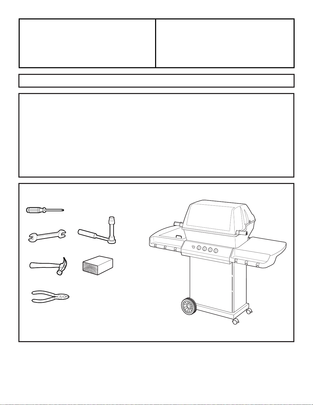
TOOLS YOU WILL NEED
Phillips screwdriver
7/16″ open end wrench or deep socket with extension
Hammer
JGGB27, JGGN27, JGGR27
Pliers
Block of wood
Page 2
2
Assembly Instructions
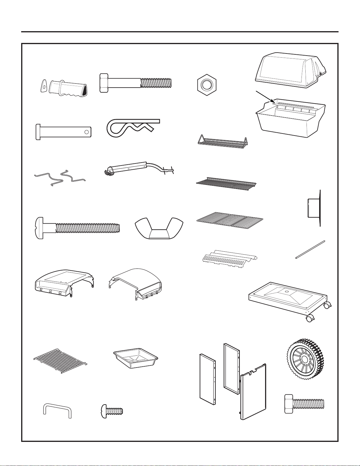
PARTS INCLUDED (Not all models have all parts)
Handle and Spacer (2)
Lid Hinge Bolt (2)
Side Grid (1)
Handle Bolt (2)
Nut (14)
Wheel (2)
Clip (2)
Shelf Handle (1) Screw (2)
Wing Nut (2)
Left Side Burner/Shelf (1) or
Left Side Shelf (1)
(Depending on model)
Lid (1)
Swing Basket (1)
(on some models)
Warming
Rack (1)
Side-by-side
Grid (3)
Flav-R-Wave
®
* (1)
LP Tank
Retainer (2)
Base Cart (1)
Grill Bottom (1)
Right Shelf (1)
Disposable Aluminum
Drip Pan (1)
Push Nut (2)
Grid Lifter (1)
Large Bolt (2)
Side Panel (2)
Front Panel (1)
Bolt (6)
Axle Rod (1)
Rotisserie
Burner (1)
(on some models)
*Flav-R-Wave®is a registered trademark of Onward Multi-Corp, Inc.
Page 3
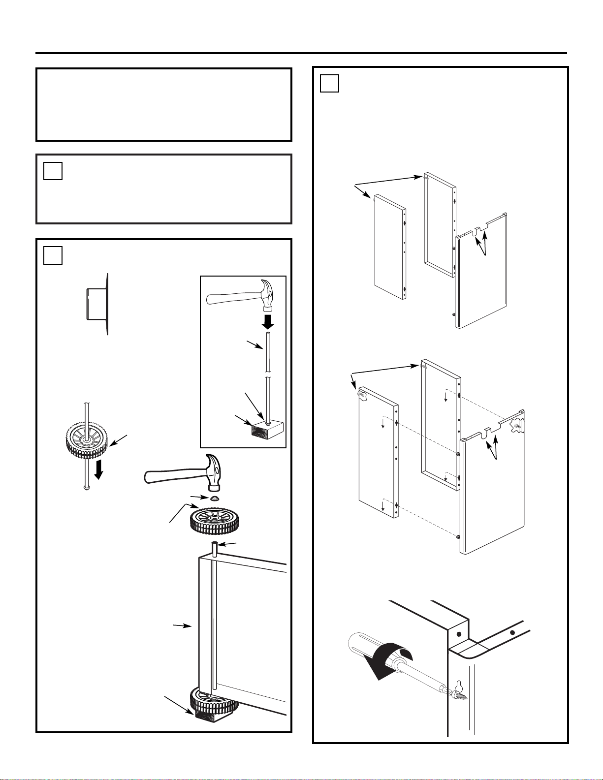
3
• Carefully cut open the box, remove
the contents and group like parts together.
UNPACK THE GRILL
1
Assembly Instructions
1. Hammer a push nut onto the
end of the axle rod.
2. Slide a wheel onto the axle rod.
3. Slide the base
cart onto the
axle rod.
Hammer a
push nut onto
the end of the
axle rod.
ASSEMBLE THE BASE CART
2
1. Peel off the protective shipping film from the front
panel, if present.
2. Stand the side panels on end with the bolts at the
top. Stand the front panel on end with the cutouts
at the top.
3. Hook the front panel screw heads (4) into the
keyhole slots on the side panels.
4. Push the front panel down so that the screw heads
slide into the lower neck of the keyhole slots.
Tighten the screws to lock the panels in place.
ASSEMBLE THE LOWER BASE
3
Push nut
Wheel
(outside
of wheel
against
push nut)
Side
panels
Front
panel
To aid assembly, all parts in bold type in the following
assembly steps match the illustrations shown in the
PARTS INCLUDED section.
NOTE TO ASSEMBLER
Push nut
Axle rod
Push Nut (2)
Cutouts
at top
Bolts
at top
Wheel (outside
of wheel against
push nut)
Block of
wood as
protective
base
Block of
wood as
protective
base
Base cart
Axle rod
Side
panels
Front
panel
Cutouts
at top
Bolts
at top
Tighten screws
Side
panel
Front
panel
Page 4
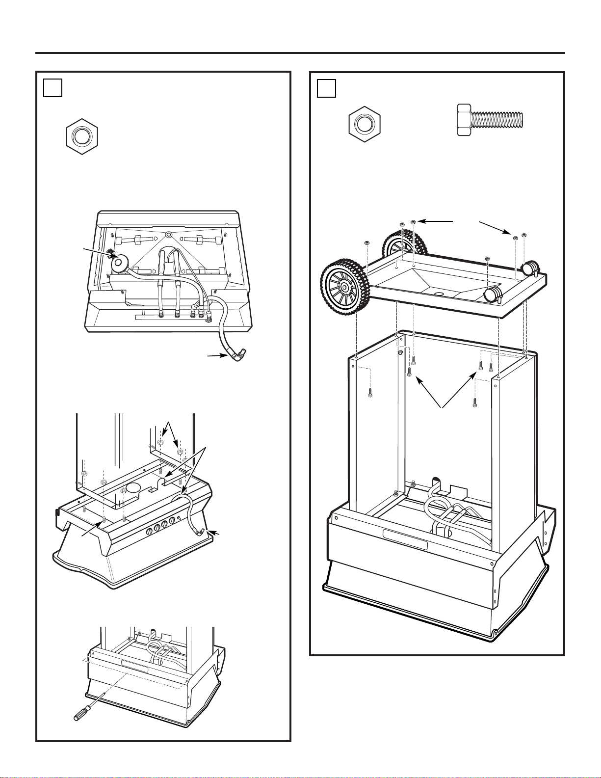
4
Assembly Instructions
1. Place the grill bottom upside down on the floor
and position the hoses as shown.
2. Turn the assembled lower base over and slide it
over the six bolts in the grill bottom. Secure in
place with six nuts.
3. Insert a Phillips screwdriver through each angled
hole and make sure the bolts are tight.
MOUNT THE BASE TO THE GRILL BOTTOM
4
1. Place the base cart over the lower base.
2. Insert six bolts from inside the lower base and
secure in place with six nuts.
MOUNT THE BASE CART
5
Side burner hose
LP tank hose
Nut (6)
Nut (6)
Bolt (6)
Front
Front
Back
Front
Back
Nuts
Bolts
Nuts
Bolts
Back
Side-burner
hose
Align side-burner
hose with U-shaped
cut-out on base
Page 5
5
Assembly Instructions
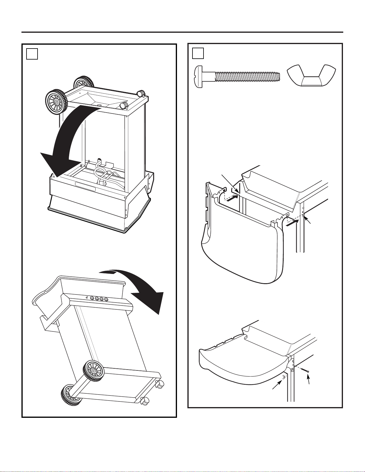
NOTE: If your model has a burner/shelf, it must be
installed on the left side.
1. Peel off the protective shipping film from the side
shelves, if present.
2. Hook the bottom slotted holes of the shelf onto the
bottom bolt heads. Repeat for other shelf on the
other side.
3. If desired, raise the shelf and hook it in the up
position. It may also be locked in the up position
by inserting a large bolt in the center back hole
and securing it with a wing nut.
INSTALL THE SIDE SHELVES
7
1. From the back side, lower the base to the floor.
2. From the back top side of the grill, lift the grill
onto its wheels.
SET THE GRILL ON ITS WHEELS
6
Large bolt
Wing nut
Back
Back
Front
Wing Nut (1 or 2)
Large Bolt (1 or 2)
Front
Hook on
bottom bolt
Back
Front
Hook on
bottom bolt
in slot
Page 6

6
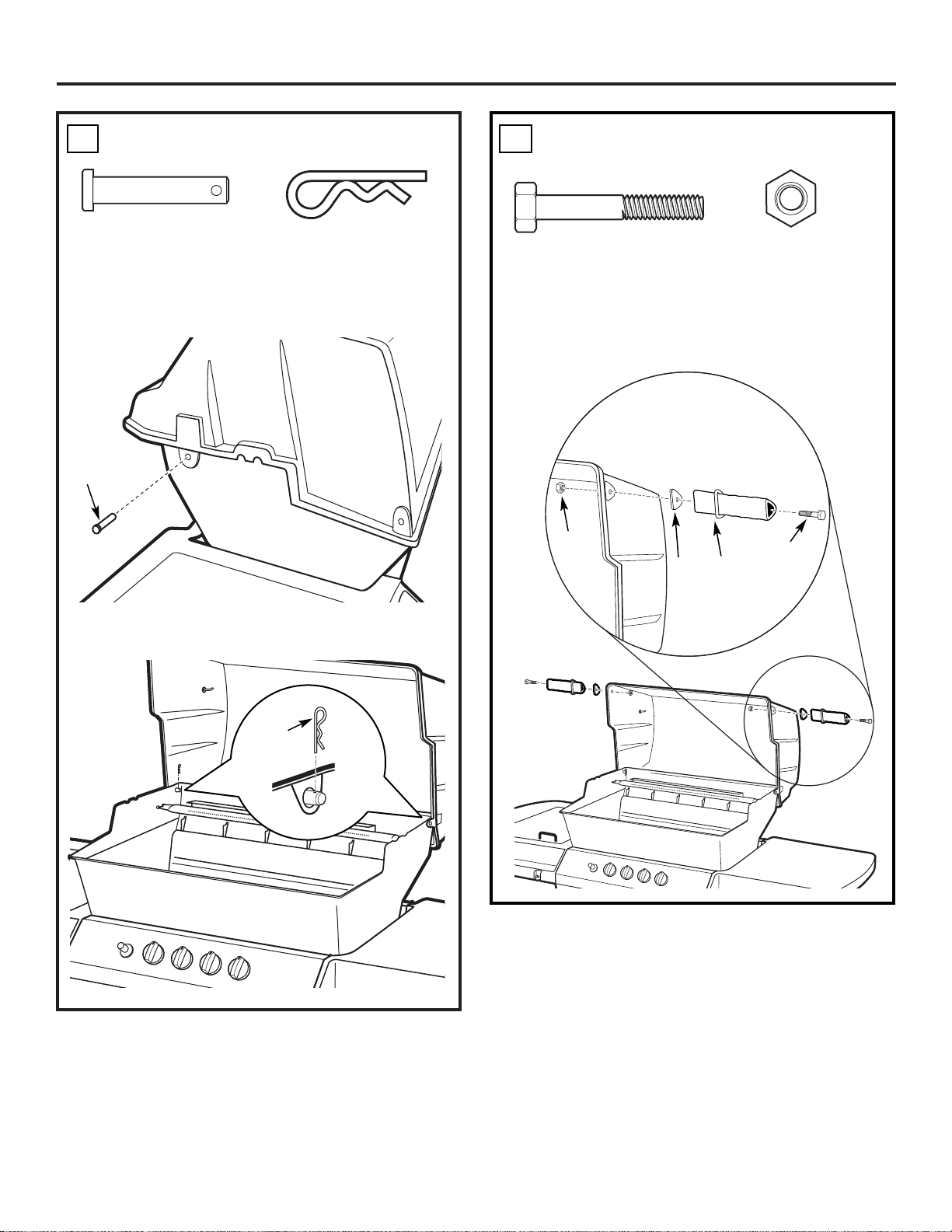
1. Hook the bottom slotted holes of the burner/shelf
onto the bottom bolt heads. Raise the shelf and
hook it in the up position.
2. Peel off the protective shipping film from the
burner shelf door and burner area, if present.
Attach the shelf handle with two screws.
INSTALL THE LEFT SIDE BURNER/SHELF
(on some models)
8
Assembly Instructions
3. Remove the side grid and peel off the protective
shipping film, if present. Guide the two pins on the
side grid into the two holes in the side
burner/shelf and lower it into position.
4. The shelf should be locked in the up position by
inserting a large bolt in the center back hole and
securing it with a wing nut.
Shelf
handle
Screws
Side burner grid
Large
bolt
Wing nut
Screw (2)
Wing Nut (1)
Large Bolt (1)
Back
Front
Front
Back
Hook on
bottom bolt
Hook on
bottom bolt
in slot
Page 7

7
1. Connect the side burner hose by pressing the
fitting into the side burner gas tube.
2. Pull the side burner hose fitting into the neck of
the keyhole bracket and hand-tighten the nut to
lock in place.
Assembly Instructions
CONNECT THE LEFT SIDE BURNER/SHELF
(on some models)
9
3. Connect the side burner electrode wire to
the connector under the control panel. (The
connector is under the control panel, on the
stem of the red igniter button).
Side burner
gas tube
Side burner
hose fitting
Make side burner
gas connection
Pull side
burner hose
fitting into
neck
Make a firm
connection
Page 8
8
Assembly Instructions
1. Place and align the lid over the grill bottom in the
closed position.
2. Insert a lid hinge bolt into each hinge.
3. Open the lid and insert a clip through the hole in
each lid bolt.
INSTALL THE LID
10
• Slide a handle bolt through a handle and spacer
and into the hole in the grill lid. Align and secure
in place with a nut using a 7/16″ open-end wrench
or a deep socket. Repeat on the other side.
INSTALL THE HANDLES
11
Lid hinge
bolt
Clip
Lid Hinge Bolt (2)
Clip (2)
Handle Bolt (2)
Nut (2)
Front
Nut
Handle
spacer
Handle
Handle
bolt
Page 9

1. Place the Flav-R-Wave® on the supports in the
bottom of the grill. The Flav-R-Wave® should
lie flat.
2. Place the side-by-side grids on the front and
back supports*.
9
ASSEMBLE THE GRILL COMPARTMENT
12
Flav-R-Wave
®
Grids
Assembly Instructions
3. Place the ends of the warming rack into the back
slots on the upper grill sides.
4. Hang the swing basket (on some models) on the
two hooks in the lid.
Warming
rack
Swing
basket
* See the Owner’s Manual for available grid positions
for your model.
Page 10

10
• Place the end of the LP tank retainer in the hole
in the base. Flex the retainer and place the other
end in the other hole in the base. Repeat for the
other side.
ATTACH THE LP TANK RETAINERS
13
• Your grill is designed
to be used with an LP
gas tank equipped
with the new QCC-1
Quick Closing
Coupling system
and the new
OPD handwheel.
• The QCC-1 system
is recognizable by
the external threads
on the inlet port of
the valve.
• The OPD handwheel
is recognizable by its
shape as shown.
• The LP gas tank used with this grill must NOT have
a capacity larger than 20 lbs. (9kg).
• Approximately: 18″ (46 cm) high
12″ (31 cm) diameter
• These tanks are available from your local gas
grill dealer.
WARNING: Make sure that the cylinder
valve on the LP tank is closed.
Close by turning clockwise.
1. Place the LP tank on the grill base with the LP tank
connector facing to the right of the grill.
2. Center the LP tank and lower the retainers into
place around it.
MOUNT THE LP TANK
(not included—obtain locally)
14
Assembly Instructions
LP tank
retainer
Right side
Back of grill
LP tank
valve
QCC1
¤
NEW OPD
HANDWHEEL
N
E
P
O
L
P
S
-
G
A
O
D
P
C
L
O
S
E
Page 11

11
Assembly Instructions
1. Remove the plastic cover from the LP
tank connector.
2. Screw the regulator coupling (on the gas hose)
onto the LP tank connector in a clockwise direction.
Hand tighten only.
NOTE: The regulator coupling tightens clockwise
and will not allow gas to flow unless the connection
is tight. The connection requires tightening by
hand only.
WARNING: Do not use a wrench to
tighten the connection. Using a wrench could damage
the regulator coupling and could cause a gas leak.
The regulator vent holes should be at 3 o’clock.
They should not be pointed up.
CONNECT THE LP TANK
15
LP tank
connector
Regulator
coupling
Regulator
(vent holes
at 3 o’clock)
Read your Owner’s Manual carefully for proper use
and care of your grill.
READ YOUR OWNER’S MANUAL
18
• Insert the disposable aluminum drip pan into the
drip pan holder.
INSERT THE DRIP PAN
17
Disposable
drip pan
Drip pan
holder
TO TEST FOR LEAKS:
• Prepare a soap solution of one part water, one part
liquid detergent.
1. Extinguish any open flame or cigarettes in the area.
2. Make sure the LP tank valve is closed and the grill
controls are turned to OFF.
3. Connect the LP gas tank. See the CONNECT THE
LP TANK step.
4. With a full LP tank, open the tank valve slowly.
TEST FOR LEAKS
16
WARNING —A complete gas tightness
check must be performed at the final use site.
DO NOT use grill until all connections have been
leak tested.
5. Wet each connection with the soap solution.
6. A leak is identified by a flow of bubbles from the
area of the leak.
7. If a leak is detected, close the LP tank valve, tighten
the connection, and retest (Steps 4–6).
8. If you smell gas, read and follow the complete Leak
Test section in the Owner's Manual.
9. If the leak persists, contact your grill dealer for
assistance. Do not attempt to operate the grill
if a leak is present.
TEST FOR LEAKS (CONTINUED)
LP Tank Connection
Page 12

12
PARTS LIST
Page 13

13
GENERAL ELECTRIC PARTS CATALOG
REF. NO. PART NO. PART DESCRIPTION JGGN27 JGGB27 JGGR27
1. 10909-T60 CASTING BOTTOM 1 1 1
2. 10473-T60 CASTING TOP 1 1 1
3. 164D4387 NAMEPLATE 1 1 1
3A. 164D4587 NAMEPLATE LOGO 1 1 1
4. 10958-K70GE TOP CASTING INSERT 1 1 1
5. 10571-6 HEAT INDICATOR 1 1 1
6. 10240-15 HINGE PIN 2 2 2
6A. S21237 HINGE PIN SPACER 2 2 2
7. S21233 HINGE PIN CLIP 2 2 2
8. 10222-T625 FLAV-R-WAVE® 1 1 1
9. 10225-T626 GRID–CAST 3 3 3
11. 10225-T628 GRID–WARMING RACK 1 1 1
12. 10225-T627 SWING BASKET - - 1
13. Y-11797 BOLT SWING BASKET 2 2 2
15. 10390-T501 BURNER/VENTURI ASSEMBLY 1 1 1
17. 10342-21 IGNITOR 1 - 10342-22 IGNITOR - 1 1
18. 10342-T301 ELECTRODE 1 1 1
21. 10440-D60 CONTROL ASSEMBLY LP–2V 1 - 10440-D62 CONTROL ASSEMBLY LP–3V - 1 10440-D66 CONTROL ASSEMBLY LP–4V - - 1
21A. S10125 HOSE–SIDE BURNER LP - 1 1
21B. S10160 HOSE–REAR BURNER IMP LP - - 1
22. 10114-18 HOSE & REGULATOR LP–QCC1 1 1 1
23. 10472-K37 CONTROL KNOB 2 3 4
30. 164D4376 DECO PLATE 2V 1 - 164D4375 DECO PLATE 3V - 1 164D4374 DECO PLATE 4V - - 1
31. 10194-R651 CONTROL COVER 1 1 1
32. 10184-R001 VALVE BRACKET 1 1 1
33. 10086-D63 DECO PLATE STRIP 1 1 1
35. 10184-K651 SUPPORT - CASTING - LEFT 1 1 1
36. 10184-K661 SUPPORT - CASTING - RIGHT 1 1 1
37. 10184-K581 SUPPORT - SIDE SHELF - LEFT 2 2 2
38. 10184-K591 SUPPORT - SIDE SHELF - RIGHT 2 2 2
39. 10958-K831 BRACE - REAR 1 1 1
40. 10958 -K5891 BASE 1 1 1
41. 10958-K851 BRACE - FRONT 1 1 1
42. 10958-K89 FRONT PANEL - SS 1 1 1
43. 10958-K861 SIDE PANEL - BLACK 2 2 2
47. 10184-K19A LP TANK RETAINER 2 2 2
50. 10711-K561 SHELF - SIDE - RIGHT 1 1 1
51. 10711-K562 SHELF - SIDE - LEFT 1 - 10711-K563 SHELF - SIDE BURNER - 1 1
56. 10892-8 WHEEL 2 2 2
Page 14

14
GENERAL ELECTRIC PARTS CATALOG (cont.)
REF. NO. PART NO. PART DESCRIPTION JGGB27 JGGN27 JGGR27
65. S13008 ROTISSERIE BURNER - - 1
68. S21362 SPRING - - 1
73. S21420 PUSH NUT 2 2 2
74. Y-6616 BOLT 1/4-20 x 11⁄2 222
75. 10338-145 HANDLE 2 2 2
76. 10239-6 HANDLE WASHER 2 2 2
78. 10892-14 CASTOR 2 2 2
79. Y-11545 SCREW - 1/4-20 x 13⁄8 444
80. Y-11549 SCREW - 1/4-20 x 17⁄8 10 10 10
82. Y-12860 SCREW - 1/4-20 x 1 18 18 18
83. S21014 BOLT - 1/4-20 x 3/4 6 6 6
84. S15178 AXLE 1 1 1
87. Y-11793 NUT 1⁄4-20 16 16 16
88. Y-11598 WING NUT 1⁄4-20 2 2 2
90. Y-12286 LAG BOLT - 5/16 x 4 4 4 4
97. S21124S STAINLESS STEEL SCREW - 8 x 1/2 6 6 6
98. S21124 SCREW - 8 x 1/2 28 28 28
99. Y-12646 SCREW – SHOULDER 8 x 1/2 - 2 2
104. Y-12835 SCREW – 6-32 x 1/4 -- 4 4
105. Y-29307 NUT – 10-24 - 5 5
108. PB20-60 LID HANDLE - 1 1
109. S21136 SCREW – 8-32 x 3/8 2 5 5
110. 10225-T10 GRID - 1 1
111. 10390-T10 SIDE BURNER - 1 1
113. 10342-T08 ELECTRODE – SIDE BURNER - 1 1
114. 10393-K40 COVER – SIDE BURNER - 1 1
115A. Y-29305 SCREW – 10-24 x 3/8 - 4 4
115B. Y-29305S STAINLESS STEEL SCREW - 10-24 x 3/8 2 4 4
117. 10393-K50 SHELF – SIDE BURNER - 1 1
118. 10393-T221 SHIELD – SIDE BURNER - 1 1
121. 10184-K613 CASTOR SUPPORT 1 1 1
123. S15115 GREASE PAN – DISPOSABLE 2 2 2
To obtain replacement parts, call during normal business hours: 866.GE.GRILL (866.434.7455).
Page 15

15
NOTES
Page 16

Part No. 164D4290P035
Pub. No. 49-80077-1
05-01 JR Printed in Canada
 Loading...