


ge.com
©
°v,,,_
Safety Instr_ions ....... 2-7
Operating Instruaions
Aluminum Foil ............ ] 5
Burners ............... 10, l l
(:lock .................... 13
Feauwes ................ 8, 9
Griddle .................. 12
()yen ................. 13-18
Baking and Roasting ...... 15
Broiling .............. 16, 17
Broiling (;uide ........... 17
Clock and Timer ......... 13
I Jght ................... 14
Oven Control ............ 14
Power Outage ............ 14
Preheating .............. 15
Them_osmt Ailjustment .... 18
Vent .................... 14
Care and Cleaning
Broiler Compartment ...... 24
Broiler Drawer . ........... 24
Broiler Pan and Grid ....... 23
Burner Assemblies ...... 20, 21
Burner (;rams ............. 22
Control Panel and KJ_obs ...25
Cooktop Surfi_ce .......... 22
Griddle .................. 19
Kick Panel ................ 24
Lift-off (h'en Door . ........ 23
()yen Bottom ............. 23
()yen Interior ............. 25
()yen Light Replacement ...24
Oven Vents ............... 25
Sheh'es .................. 24
Stainless Smel Surfi_ces ..... 22
Installation
Instructions ........... 26-38
Air Ailjustment ............ 37
Anti-Tip Device ......... 30, 38
Assembling
Surfi_ce Burners ........... 35
Checking Burner ignition . . .36
Connecting the Range
to Gas ................ 31-33
Dimensions and
Clearances ............... 29
Electrical Connections ...34, 35
Leveling the Range ........ 37
Location ................. 30
LP ...................... 38
Model and Serial Number
Location ................. 30
Troubleshooting Tips...39, 40
Consumer Support
Constlll/er
Support .......... Back Cover
Product Regdstrafion .... 41,42
V\hrranty ................. 43
jonson)
}<;Bsso
Write the model and serial
numbers here:
Model #
Serial #
You can find them on a label on the
front of the range behind the kick
panel or broiler compartment.
18305580P191
49-85188 OS-OSJfl

IMPORTANTSAFETYINFORMATION.
READALLINSTRUCTIONSBEFOREUSING.
WARNING!
For your safe_ the information in this manual must be followed to minimize the risk of fire or explosion,
electric shock, or to prevent property damage, personal injury, or loss of life.
WARNING:If the information
in this manual is not followed exactly,
a fire or explosion may result causing
property damage, personal injury
®
WARNING!
or death.
-- Do not store or use gasoline or other
flammable vapors and liquids in the
vicinity of this or any other appliance.
ANTI-TIPDEVICE
ALL RANGES CAN TIP
@ INJURY TO PERSONS
COULD RESULT
@ INSTALL AN_tiP
DEVICES PACKED WITH
RANGE
INSTRUCTIONS
ANTI-TIPDEVICE
All rangescan tip and injury could result.
- WHATTODOIF YOU
SMELLGAS
@ Do not try to light any appliance.
Do not touch any electrical switch;
do not use any phone in your
building.
@ Immediately call your gas supplier
from a neighbor's phone. Follow the
gas supplier's instructions.
If you cannot reach your gas supplier,
call the fire department.
-- Installation and service must be
performed by a qualified installer,
service agency or the gas supplier.
Toprevent accidental tipping of the range, attach it to the wall by installing the Anti--tip device supplied.
If the Anti--tip device supplied with the range does not fit this application, use the universal Anti--17p
device WB2X7909.
Tocheck if the device is installed and engaged properly, carefully tip the range forward. TheAnti--tip
device should engage and prevent the range from tipping over.
If you pu]] the range otlt t)om tile wall for any reason, make sure fl)e device is properly engag>d
when you push the range back against the wall. If it is not, flmre is a possible risk of the rang>
tipping ox>r and causing i,lju_ T if you or a child stand, sit or lean on an open door
Please refer to the Anti-Tip device infollnation in this manual. Failure m take this precaution
could result in tipping of the rang_ and ilIjtlI>

ge.com
WARNING!
IMPORTANTSAFETYNOTICE
The California Safe Drinking Water and ToxicEnforcement Act requires the Governor of California to
publish a list of substances known to the state to cause birth defects or other reproductive harm, and
requires businesses to warn customers of potential exposure to such substances.
Gasappliances can cause minor exposure to four of these substances, namely benzene, carbon
monoxide, formaldehyde and soot, caused primarily by the incomplete combustion of natural gas or
LP fuels. Properly adjusted burners, indicated by a bluish rather than a yeflow flame, will minimize
incomplete combustion. Exposure to these substances can be minimized by venting with an open
window or using a ventilation fan or hood.
SAFETYPRECAUTIONS
Have the installer show you the location of the range gas shut-off valve and how to shut it off if necessary.
;_;Hate your rang_ installed and properly ;_; Plug your rang_ into a 190_\_lt grounded
grounded by a qualified installer, in
accordance with the Installation Insuucdons.
Any adjustment and service should be
perfo,_ned only by qualified gas rang>
installers or service technicians.
_:;i_'Do not attempt to repair or replace any
part of your range unless it is specifically
recommended in this manual. All other
service should be refetTed to a qna]ified
technician,
outlet only. Do not remove the round
grounding prong fiom dm ping. If in doubt
about the grounding of the home electrical
system, it is your personal responsibility and
obligation to haxe an ungrounded outlet
replaced wifll a properly grounded,
d_ree-prong outlet in accordance with
the National Electrical (;ode. Do not use
an exmnsion cord with this appliance.
3

IMPORTANTSAFETYINFORMATION.
READALLINSTRUCTIONSBEFOREUSING.
SAFETYPRECAUTIONS
_5_iLocate the range out of kitchen traffic path ;fi:,i
and out of drafty locations to prexent poor
air circulation. E:,:
_: Be sure all packaging materials are remox.ed
flom tile rang.e befbre operating it to
prex.ent fire or smoke damag.e should the
packaging material ignite.
E:':Be sure your range is correctly adjusted by
a qualified service technician or installer fox
tile type of gas (natural or IP) flint is to be
used. Your rang.e can be converted for use
with either type of gas. See the Installation
of the range sect.ion.
WARNING: xeseadjnstmentsmnst
be made 1)5' a qualified service technician
in accordance with rixe mannlaactuier's
instructions and all codes and requirements
of the authority havingjm-isdiction. Failure
m follow fllese instructions could x.esult in
serious injm T or proper U damag.e. The
qualified ag.ency performing flxis work
assumes responsibility fox the conversion,
E:.:After prolong.ed use of a range, high floor
temperaun.es m W result and many floor
cox.erings will not wifllstand this kind of use.
Ne_.er install the rang.e o_.er vinyl die or
linoleum flint cannot wifllsmnd such type
of use. Nex.er install it dix.ecflv ox.er interior
kitchen carpeting.
q?{::Do ,lot lem.e childi.en alone or unattended
where a rang.e is hot or in operation. They
could be seriously burned.
E:,IDo not allow anyone to climb, stand or hang
on the ox.en doox; broiler comparunent or
cookmp. They could damag.e tile range and
ex.en tip it ovel; causing sex.ere personal
injm T.
_:_CAUTION:hems of interest to
children shouM not be stored in cabinets
abox.e a range or on tile backsplash of a
rang.e--children climbing on the rang>
m reach items could be seriously injured.
A WARNING:NEVERusethis
appliance as a space heater to heat or
warm tile room. Doing so may result
in carbon monoxide poisoning and
4
ox.erheating of the oven.
Clean only parts listed in this Owner's
Manual.
Nex,er wear loose fitting or hanging garments
while using the appliance. Be careflfl when
reaching fox items stored in cabinets ox.er tim
rang.e. Flammable material could be ignited
if brought in contact with flame or hot ox.en
snifitces and may cause sex.ere bniTis.
_{:;Do *lot store flammable materials in an
ox.en, a rang.e broiler, behind the kick panel
or near a cooktop.
E:,:Do ,lot store or use combnsfible materials,
gasoline or oflxer flammable vapors and
liquids in rixe vicinity of this or any oflxer
appliance.
_7_:Do ,lot let cooking gTease or other
flammable materials accunmlate in or
near the rang.e.
E:.:Do ,lot use water on grease fires. Nex.er pick
up a flaming pan. Tm_n the controls off'.
Smother a flaming pan on a surthce burner
1)5'cox.ering tile pan completely with a
well-fitting lid, cookie sheet or fiat uay.
Use a multi-puq)ose d, T chemical or
tbam-tvpe fire extinguisher
Flaming gx.ease outside a pan can be put
out by co\.efing it with baking soda ox;
if available, by using a muld-pnrpose dt T
chemical or foam-type fire exdnguishen
Flame in flxe oven can be smothered
completely by cloong the ox.en door and
turning tile control to off or by using a
nmld-purpose d U chemical or foam-type
fire exdnguishen
E:.:i,et rim burner grates and other surfaces
cool befox.e touching them or leaving them
where children can x.each them.
_: Nex.er block tile \.ents (air openings) of tile
rang.e. They provide the air inlet and outlet
that are necessa U for flxe rang.e to operate
i)ioperly with conect combustion. Air
openings are located at the rear of tim
cooktop, at the top and bottom of the oven
doox; and at tile bottom of tile range under
the broiler compartment or kick panel.
_ti_:Large scratches or impacts to glass doors can
lead to broken or shauered glass.

g_com
COOKMEATANDPOULTRYTHOROUGHLY...
Cook meat and poultry thoroughly--meat to at least an INTERNAL temperature of 160°Fand poultry to
at least an INTERNAL temperature of 180°F.Cooking to these temperatures usually protects against
foodbome illness.
OVEN
Stand away from the range when opening the door of a hot oven. Thehot air and steam that escape
can cause bums to hands, face and eyes.
;_;Do not use file oven for a storage area.
Imms stored ill tile ox>n call ignim.
_i_Kee I) the oxen free from grease buildup.
_::Place tile oxen shelx_s ill tile desiIed
position while tile ox>n is cool.
_{:;Pulling out tile shelf m file stop-lock is a
convenience in lifting heavv foods. It is also
a precaution against bunls from touching
hot SUl_tces of tile door or oxen walls. Tile
lowest position is not designed m slide.
_{:;Do not heat unopened food containers.
Piessure could build up and tile container
cotl]d btlist, causing all iI)J/lI>
WARNING:NEVERcover
any slots, holes or passages ill tile oven
l)ottom or cover all end re shelf will/
materials such as ahmlinmn foil. Doing
so blocks air flow through tile oxen and
may cause carbon monoxide poisoning.
Aluminum foil lining_ may also trap
heat, causing a fire hazard.
_?_::Do not use aluminum foil an_vhere ill tile
o_en except as described ill tills mamlal.
Misuse could result ill a fire hazard or
damag> to tile rang>.
:fi:,:V_]len using cooking or roasdng bags in tile
ox>n, follow tile manulCacturer's directions.
_ Do not use your o\_n to dry newspapers.
If ox>rheamd, tiley call catch fire.
_:;Use only glass cookwaIe tilat is
recommended for use ill gas ox>ns.
_fi:,:Always iemove tile broiler pan fiom rang_
as soon as you finish broiling. Grease left ill
tile pan call catch fire if ox>n is used witilout
iemoving tile giease flom tile broiler pan.
_7{:__A]len broiling, if meat is too close to tile
flame, tile t_atmay ignim. Trim excess t_atm
plevent excessi\'e flaiemps.
_7{:;Make sure tile broiler pan is ill place
coixecfly m reduce tile possibility of
grease fires.
;fi:':H'you should haxe a grease file ill the broiler
pan, turn off tile ox>n conuol, and keep
tile broiler comparunent and oxen door
closed to contain fire/mfil it bums out.
_i:,:For safe.U and proper cooking perfomlance,
always bake and broil with the ox>n door
closed.

IMPORTANTSAFETYINFORMATION.
READALLINSTRUCTIONSBEFOREUSING.
WARNING!
SURFACEBURNERS
Use proper pan size--a void pans that are unstable or easily tipped. Select cookware having flat bottoms
large enough to cover burner grates. Toavoid spillovers, make sure cookware is large enough to contain
the food properly. Thiswill both save cleaning time and prevent hazardous accumulations of food, since
heavy spattering or spillovers left on range can ignite. Usepans with handles that can be easily grasped
and remain cool.
_{:;Always use the LITE position when igniting
the top btn_mrs and make sure tile hnl_ers
have ignited.
;_i:,:Ne_er leave fl_e suilZace burners unattended
at high flame settings. Boiloxers cause
smoking and gleasy spilloxers that m W
catch on file.
q_;Adjust tile top hun_er flame size so it
does not extend hevond the edge of the
cookware. Excessixe flame is hazardous,
;_i:,:Use only d U pot holders--moist or damp
pot holders on hot sni/_aces may resuh in
h/n_ls flom smam. Do not let pot holders
come near open flames when lifting
cookware. Do not use a towel or other
hulky cloth in place of a pot holden
;_i:,:When using glass cookwme, make sure it
is designed for toi>ot=range cooking.
;_i:,:To minimize the possihility of hums,
ignition of flammable mamrials and spillage,
ulm cookware handles toward die side or
hack of file range without extending over
adjacent hurners.
_:;Careflllly watch fbods heing flied at a higtl
flame seuing.
_;;Always heat £_t slowly, and watch as it heats.
;_i:,:Do not ]eme any imms on file cooktop. Tile
hot air flom tile \ent may ig_lim flammahle
imms and will increase pressure in closed
containers, which may cause them to burst.
;_i:,:If a comhinafion of oils or fiatswill be used in
flTing, stir together before heating or as t=ats
meh slowly
q_{_;Use a deep/_at thellnomemr whenever
possible to piexent oxerheating/_at hevond
tile smoking point.
;_i:,:Use the least possihle amount of/_at for
effective shallow or deep-i%t flTing. Filling
the pan too fllll of f=atcan cause spillo_ers
when food is added.
Do not flame foods on the cooktop. If you do
flame foods under the hood, mm tile £m on.
Do not use a wok on the cooking surface
if the wok has a round metal ling that is
placed oxer the hurner gram m support
the wok. Tills ring acts as a heat trap,
which may damage die hnliler gram and
hurner head. Also, it m W cause file humer
m work impropefl> Tills m W cause a
carbon monoxide lexel aboxe that
allowed hy cunent standards, iesulting
in a heahh hazard.

ge.com
;fi:,iDo not use aluminum foil m line the
giiddle. Misuse could result in a fire hazard.
;_i:,iNever lem_ tile kitchen while using tile
giiddle.
_{_Foods for flTing should be as di T as possible.
Frost on flozen foods or moisture on fresh
foods can cause hot tilt to bubble up and
ox>r tile sides of rile pan.
;fi:,iNexer uT to move a pan of hot tilt, especially
a deep laatflTer _4'ait until tile laatis cool.
;fi:,iDo not leaxe plastic items on tile cooktop--
flier may melt if left too close to tile x>nt.
_{_Kee I) all plastics away flom tile sur£_ce
blli'llers.
_; To moid tile possibility of a buiIl, always be
certain that the controls for all burners are
at the OFFposition and all grates and tile
griddle are cool before attempting to
renlo'_ e thenl.
;f; K range is located near a windoxs, do not
hang long curtains that could blow oxer tile
surface burners and create a fire hazard.
_: gyou smell gas, turn off tile gas to tile range
and call a qualified service technician. Nex>r
use an open flame to locate a leak.
;_i:':Always turn the surt_ace burner controls off
before removing cookware or tile griddle.
N Do not lift the cookmp. I,ifting the cookmp
can lead m damag> and improper operation
of tile rang>.
_i_:Do not place or store imms that can melt or
catch fire on the grates, even when tile
cookmp is not being used.
N Kee I) rang_ clean and free of accumulations
of grease or spillox_rs, which may ignite.
READANDFOLLOWTHISSAFETYINFORMATIONCAREFULLY.
SAVETHESEINSTRUCTIONS

Featuresof yourrange.
Features and appearance may vary from your model.
ge.com
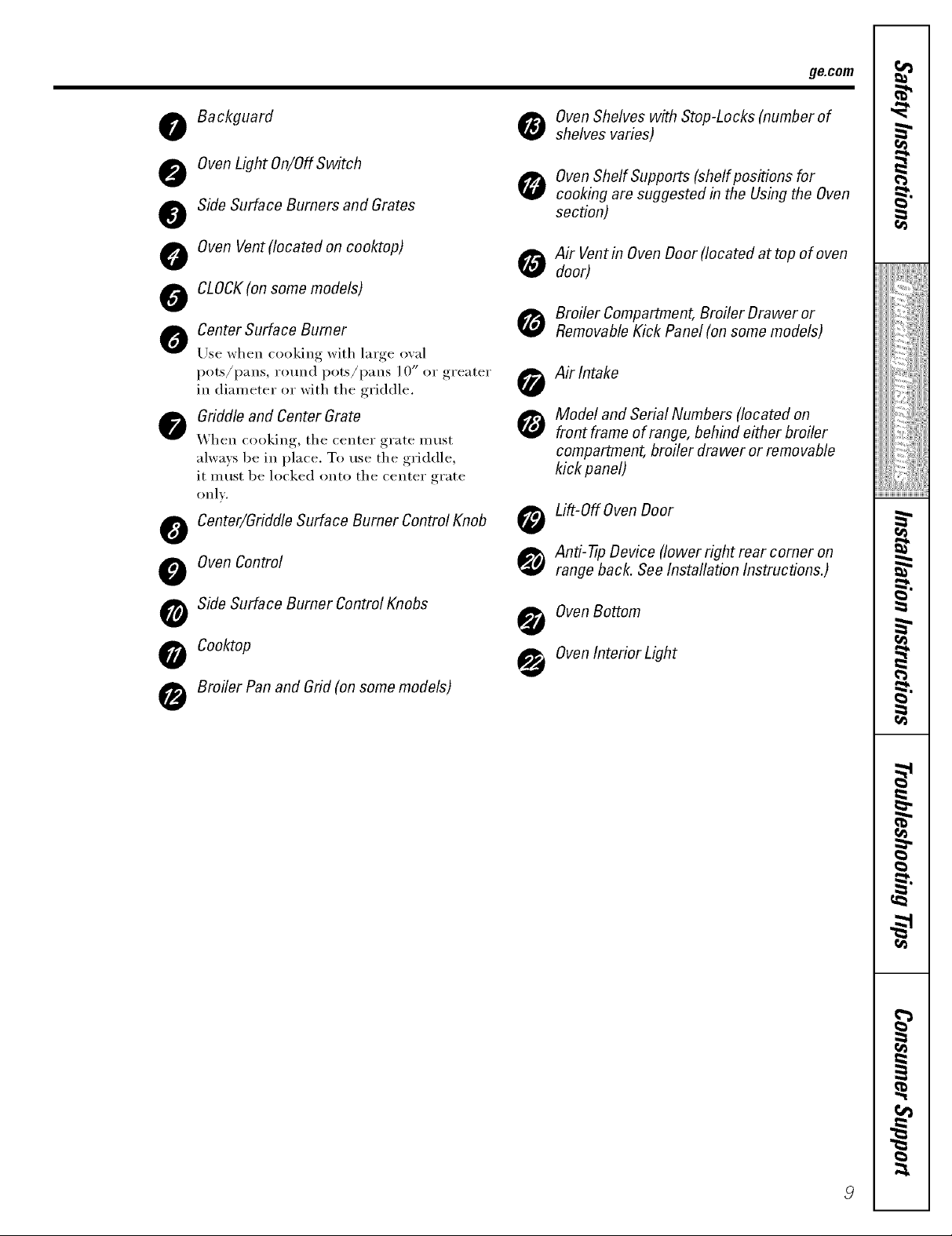
o Backguard
OvenLight On/Off Switch
@
Side Surface Burners and Grates
@
Oven Vent (located on cooktop)
0
CLOCK(on some models)
OvenShelves with Stop-Locks (number of
shelves varies)
OvenShelf Supports (shelf positions for
cooking are suggested in the Usingthe Oven
section)
o Air Ventin Oven Door (located at top of oven
door)
0
Center Surface Burner
0
Use when cooking with large oval
pots/pans, round pots/pans l 0" or greater
in diameter or with the griddle.
Griddle and Center Grate
@
When cooking, the center grate must
always be in place. To use the griddle,
it must be locked onto the center grate
only.
Surface Burner Control Knob
_ Center/Griddle Anti-tip Device (lower right rear comer on
Oven Control range back. See Installation Instructions.)
Broiler Compartment, Broiler Drawer or
Removable Kick Panel (on some models)
_ Air Intake
Model and Serial Numbers (located on
front frame of range, behind either broiler
compartment, broiler drawer or removable
kick panel)
Lift-Off Oven Door
I
_!!ii::,,_i4ii_i:il
ii_iiiii_iiii}iiii
,_"_>,,,,Hiiiiiii
iii!iiiiii_i_ii{ii¸
o Side Surface Burner Control Knobs OvenBottom
Broiler Pan and Grid (on some models)
_ ooktop OvenInterior Light
g
H
Usingthegas surfaceburners.
Throughout this manual, features and appearance may vary from your model
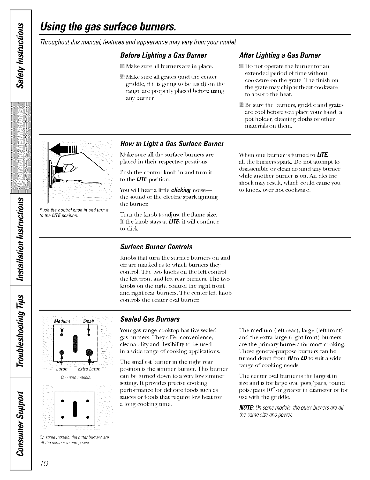
Push flTecontrol knob in and turn it
to flTeLITEposition.
Before Lighting a Gas Burner
_: Make sure all burne,_ are in place.
::Ji::Make sure all grates (and tile center
griddle, if' it is going to be used) on the
range are properly placed before using
anv btll'neI i
How to Light a Gas Surface Burner
Make sure all tile sm_hce burners are
placed in their respective positions.
Push the control knob in and turn it
to tile LIrE position.
_l, will hear a little clicking noise--
the sound of the electric spark igniting
tile burne,:
Turn tile knob to a(!jtlSt tile flame size.
If the knob stm:s at tirE, it will continue
to click.
After Lighting a Gas Burner
_: Do not operate tile burner for an
extended period of time without
cookware on the grate. The finish on
tile grate may chip without cookware
to absorb tile heat.
::Ji::Be sure tile burne,s, griddle and grates
are cool before w)u place your hand, a
pot holde,; cleaning cloths or other
materials on them.
_&]/en one burner is turned to LITE,
all tile burnex_ spark. Do not attempt to
disassemble or clean arolmd any burner
while another burner is on. An electric
shock may result, which could ca use you
to knock over hot cookware.
Medium Smal!
Large ExtraLarge
Onsome models
Surface Burner Controls
Knobs that turn tile surf hoe burners on and
offare marked as to which burne,_ they
control. Tile two knobs on tile left control
tile left fl'ont and left rear burners. Tile two
knobs on tile right control tile right fl'ont
and right rear burne,_. Tile center left knob
controls tile center owd burne,:
Sealed Gas Burners
Your gas range cooktop has five sealed
gas burne,_. They offer convenience,
cleanabilitv and flexibility to be used
in a wide range of cooking applications.
Tile smallest burner in tile fight rear
position is tile simmer burne,: This burner
can be turned down to ave, T low simmer
setting. It provides precise cooking
pedommnce for delicate foods such as
Satlces oI" f_)o(ls that I'eqtliI'e low heat for
a l(mg cooking time.
Tile medium (left rear), la,ge (left fl'ont)
and the extra large (right front) burne,_
are the prhna,?' burne,_ for most cooking.
These general-puq)ose burne,_ can be
turned down fl'om HI to LOto suit a wide
range of cooking needs.
Tile center owd burner is tile la,gest in
size and is for large oval pots/pans, round
pots/pans 10" or greater in diameter or for
use with the griddle.
NOTE: Onsome models,theouter burnersareaft
the samesize andpower
Of? some models, the outeY borRers aye
all the same size and powe_
10
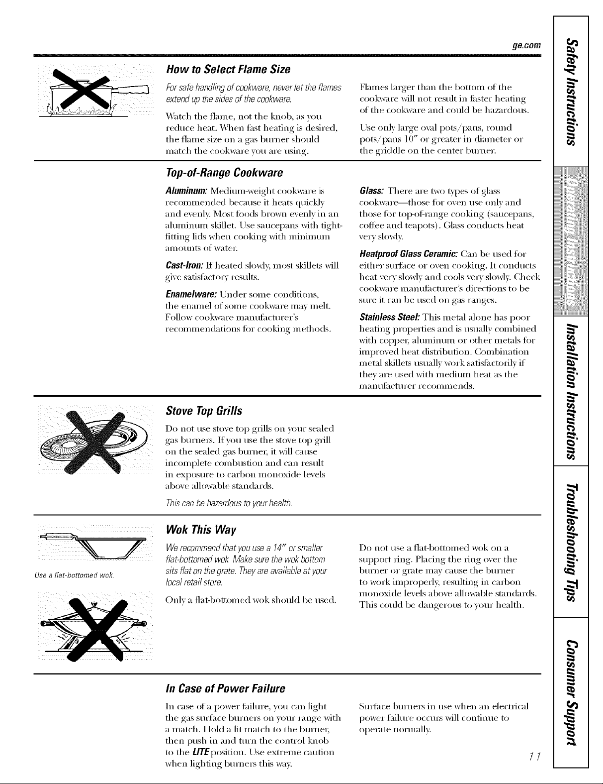
How to Select Flame Size
ge.cem
Forsafe handlingof cookware,neverlit the flames
extendup thesides of the cookware.
_'atch tile flame, not tile knob, as you
reduce heat. _4]/en tast heating is desired,
tile flame size oil a gas burner should
match tile cookware you are using.
Top-of-Range Cookware
Aluminum: Medium-weight cookware is
recommended because it heats quickly
and evenly: Most foods brown evenly in an
aluminum skillet. Use saucepans with tight-
fitting lids when cooking with minimum
}llllO/Ints of watei:
Cast-Iron: If heated slowly, most skillets will
give satistactorv results.
Enamelware: Under some conditions,
tile enaillel o[ SOIl/e (-ookware ill}iv illelt.
Follow cookware inanufilcturer's
i'eCOll/illendations tor cooking illethods.
Flames larger than tile bottom of tile
cookware will not result in fi_ster heatino
of tile cookware and could be haau'dous.
Use onl) large oxd pots/pans round
pots/pans 10" or greater in diameter or
tile griddle on tile center burner.
Glass: There are two t},,pes of glass
cookware--those tot oven/Ise only and
those fin" toi>of-range cooking (saucepans,
coffee and teapots). Glass conducts heat
very slowly.
Heatproof Glass Ceramic: Can be used tot
either smJhce or oven cooking. It conducts
heat very slowly and cools veI_' slowly. Check
cookware manufi_cturer's directions to be
sure it can be used on gas ranges.
Stainless Steel: This metal alone has poor
heating properties and is usually combined
with coppei; ahnninum or other met;ds for
improved heat distribution. Combination
metal skillets usually work satisfi_ctofilv if
they are used with medium heat as tile
IIla n tllilcttli'ei" i'ecoii/iilends.
I
_!!ii::,,_i_iiiii_i:il
ii_iiiii_iiii}ii;i
iii!iiiiii_i_ii{ii¸
Usea flat-bottomed wok.
Stove TopGrills
Do not use stove top grills on your sealed
gas burners. If'you use tile st(we top grill
on the sealed gas burnei; it will cause
incomplete combustion and can result
in exposure to carbon monoxide levels
above allowable standards.
Thiscanbehazardousto yourhealth.
Wok This Way
Werecommendthat youusea 14" orsmaller
flat-bottomedwok Makesure the wok bottom
sits flat on thegrate. Theyareavailableat your
local retail store.
Onl) a fiat-bottomed wok should be used.
In Case of Power Failure
Do not use a fiat-bottomed wok on a
support ring. Placing tile IJng over tile
burner or grate may cause tile burner
to _mrk improperl> resulting in carbon
monoxide levels above alh)wable standards.
This could be dangerous to your health.
7,
g
}
In case (ff a power fidlure, you can light
tile gas surfi_ce burners on your range with
a match. Hold a lit match to tile burnei;
then push in and mrn tile control knob
to tile LlTEposifion. Use extreme caution
when lighting bumeI_ this way.
Sm_iace burnei_ in use when an electrical
power fifilure occurs will contintle to
operate noi_nallv:,
//

Usingthegriddle.
UndersideO iddle
"U'_locks
Place the "U" locks onto the center
fingers on the center grate.
Yi_ur non-stick coated griddle provides
_lIl extra-large cooking Stli'J[ilce for Illeats,
pancakes or other toed usuall', prepared
in a ti'ving pan or skillet.
How to Insert the Griddle
A CAUTION:Placeandremovethe
griddle only when all grates andgriddle are cool
and all surface units are turned OFF.
The griddle can only be used with the
center burner and must be locked into
place on the center ,rate
Using the Griddle
NOTE."Yourgriddlewilldiscolorovertimeasit
becomesseasonedwithuse.
Place the "U" loc!<s on the tmde_ide ot
the griddle over the center finge_ of the
center grate.
Move the griddle back-and-iin'th to make
sure it is locked in place.
Most gfiddled fl_ods require cooldng
on a preheated sm'fi_ce. Preheat g_ddle
according to the guide below, then switch
to the desired cook setting.
TypeofFood Preheat MaximumQuantity
Conditions Recommended
Warming none 7stacked
Tortillas
Pancakes Highfor 6
3 minutes
Hamburgers Mediumfor 4-flattened out
5minutes
FriedEggs Mediumfor 4
5minutes
Bacon Highfor 4
5minutes
Breakfast None-nooil 13
SausageLinks
HotSandwiches Highfor6 4
(suchas minutesthen
GrilledCheese) Mediumfor
4 minutes
IMPORTANTNOTES:
_:Avoidcookingextremelygreasyfoodsandbe
carefulof greasespi//-overwhi/ecooking.
_: Donotuseoilonthegriddleforextendedlengths
oftime.Permanentstainingand/orcrazelineson
thesurfacecouldresu/L
!;?:Donot cookmilk products(suchas frenchtoast)
onthe gndd/e.Permanentstainingand/or craze
lineson the surfacecould resulL
iJi::Neverplaceorstoreanyitemsonthegriddle,
evenwhenitisnotin use.Thegriddlecan
becomeheatedwhenusingthesurrounding
burners.
iJi::DonotoverheatHegriddle.Leawngthe
griddleburneronatHIforanextendedamountof
timewithoutfoodcandamagethenon-stick
coating.
12
Usingthe clock and timer, ge.com
Throughout this manual, features and appearance may vary from your model.
f
4b
i i¸i¸
4b
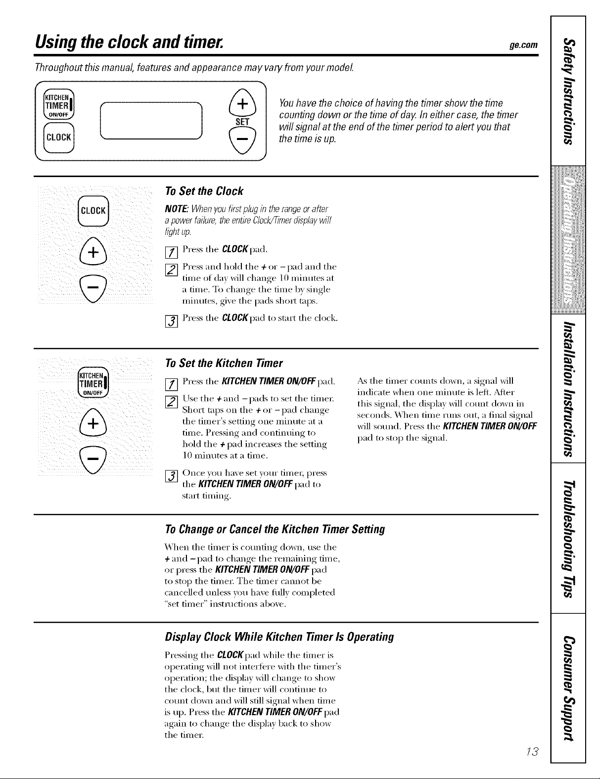
Youhave the choice of having the timer show the time
counting down or the time of day. In either case the timer
will signal at the end of the timer period to alert/ou that
the time is up.
ToSet the Clock
NOTE."Whenyoufirst p/ugin the rangeor after
apower failure, theentireClock_mer displaywill
/ight up.
[] Press the CLOCKpad.
[] Press and hold the + or -pad and the
time of day will chan,,e 10 minutes at
a time. To change the time by single
minutes, give the pads short taps.
[] Press the ClOCKpad to start the clock.
To Set the Kitchen Timer
[] Press the KITCHEN TIMER ON/OFFpad.
[_] Use the +and -pads to set the time_:
Short taps on the + or - I)ad change
the timer's settim, one minute at a
time. Pressim* and continuing to
hold the + pad increases the setting
10 minutes at a time.
[] Once you haxe set your fimei; press
the KITCHEN TIMER ON/OFFpad to
start timing.
_&sthe timer cotmts down, a signal will
indicate when one minute is letL _dter
this signal, the display will cotmt down in
seconds. When time rims out, a final signal
will sotmd. Press the KITCHEN TIMER ON/OFF
pad to stop the signal.
To Change or Cancel the Kitchen Timer Setting
When the timer is cotmting down, use the
+ and -pad to change the remaining time,
or press the KITCHEN TIMER ON/OFFpad
to stop the time_: The timer cmmot be
cancelled tmless um have flflly completed
"set tilller" instrtlctions above.
Display Clock While Kitchen Timer Is Operating
Pressing the CLOCKpad while the timer is
operating will not intertere with the timer's
operation; the display will change to show
the ch)ck, but the timer will continue to
COtlnt down and will still signal when tilne
is up. Press the KITCHEN TIMER ON/OFFpad
again to change the display back to show
the time_:
13

Usingthe oven.
Toavoid possible bums, place the shelves in the desired position before you turn the oven on.
Before youbegin...
The oven has 5 shelf positions.
It also has a special low shelf
position (R)for extra large items,
such as a large turke_
The shelves have stop-locks, so that when
placed correctly on the sheff supports
(A through E), they will stop heft)re
con/ing conlpletely out, and will not tilt.
_\]teI1 placing and renloving cookware,
pull the shelf out to the bunIp Oil the
shelf support.
Oven Control
Y)ur oven is controlled by a single OVEN
CONTROLknob.
It will noimallv take 30-90 seconds beiore
the flanie conies Oil. _dtei" the oven reaches
the selected tenlperature, the ()veil burner
c)'cles---_)ff conlpletely, then on with a fltl]
flame,---to nlaintain the selected
teniperamre.
Toremove a shelf, pull it toward you, tilt the
fi'ont end up and pull it ()tit.
Toreplace, place the end of the shelf
(stop-loc!<s) Oil the support, tilt up the
fi'ont and push the sheff in.
NOTE."Theshaftis not designed to s/ida out at the
specb/ low shelf (R)position.
Plastic items on the cooktop may
melt if left too close to the venL
Vent appearance and location vary.
Oven Vent
Your oven is vented through ducts at the
rear of the range. Do not block these ducts
when cooking in the oven--it is inlportant
that the flow ot hot air fl'onl the oven
and fl'esh air to the oven 1)tinier be
uninterrupted. Avoid touching the vent
openings or neai'bv Stli'l[ilces (hllJng ()veil oi"
broiler operation--they nlay beconle hot.
Power Outage
A CAUTION:Donotmakeany
attempt to operate the electric ignition oven
during an electrical power failure.
The oven or broiler cannot be lit during
a power taihII'e. Gas will not flow unless
the glow bar is hot.
_: Handlesofpotsandpansonthecooktopmay
becomehotif left toodosetothevenL
_: Donot leaveplastic or flammableitems on the
cooktop_they maymelt or ignite if left too dose
to the venL
::Ji::Donot&aveclosedcontaleersonthecooktop.
Thepressureindosedcontainersmaylecrease,
whichmaycausethemtoburst.
_: Metalitemswillbecomeveryhotif theyareleft
onthecooktop,andcouldcauseburns.
If the oven is in use when a power fifihu'e
oCCtlI_ the ()veil btlI'neI" shuts off and
cannot be re-lit until power is restored. This
is because the flow of gas is a utonlaticallv
stopped and will not resuine when power
is restored until tile glow bar has reached
operating teinpeiamre.
14
Oven Light
Use the switch on the lower controlpanel to
turn the light on or off.

The oven has a special low shelf (R)
position just above the oven bottom.
Use it when extra cooking space is
needed, for example, when cookflTg
a large turke,AThe shelf is not
designed toelide out at this position.
How to Set the Ovenfor Baking or Roasting
Your oven is not designed for open-door cooking.
[_] Close tile oven doo_: Turn tile OVEN
CONTROL knob to tile desired
temperature.
V_] Check food fi)r doneness at minimum
time on recipe. Cook longer if
necessa i'v,
[] Turn tile OVEN CONTROL knob to
OFf when baking is finished and then
i'elllOVe the food ti'om the oven,
Typeof Food Shelf Position
Frozenpies (oncookie sheet) B or C
Angel food cake, B
bundt or pound cakes
Biscuits,muffins, brownies, C
cookies,cupcakes,
layercakes,pies
Casseroles Bor C
Roasting Ror A
Preheating and Pan Placement
ge.com
Cut stirsin the foil just fike the grid.
Preheat tile oven if' tile recipe calls for it.
To preheat, set the oven at the correct
temperature. Preheating is necessary for
good results when baking cakes, cookies,
past_ y and 1)reads.
For ovens without a preheat indicator light or tone,
preheat10minutes.
Aluminum Foil
Never cover the oven bottom with
aluminum foil.
Y)t! can use aluminum fi)il to line the
broiler llan and broiler grid. Howe\'el,
you must mold the foil tightly to the
grid and cut slits in it just like the grid.
Oven Moisture
As vom" oven heats up, tile temperature
change of tile air in tile oven may cause
water droplets to fl)rm on tile door glass.
These droplets are hamfless and will
e\'al)orate as tile oven contintles to heat Ill),
Baking results will be better if 1)aking
pans are centered in tile oven as much
as possible. Pans should not touch each
other or tile walls of tile oven. If you need
to use two shelves, stagger tile pans so one
is not directly above tile other; and leave
approximately 11/->"between pans, fl'om
the fl'ont, back and sides of the wall.
Muminum fl)il may also be used m catch
a spillove_: To do so, place a small sheet of
fi)il on a lower shelf several inches below
the fl)od.
Never entirely cover a shelf with alumimm_
fi)il. This will distaff) tile heat circulation
and result in poor baking.
15

Usingthe oven.
Broiling (onsome models)
Broiling is cooking fl)od by direct heat fl'om
above the tood. Most fish and tender cuts of
meat can be broiled. Follow these directions
to kee I) spattering and smoking to a
minimum.
Ybur range has a compartment below the
oven fi)r broiling. []
Both the oven and broiler compartment doors
must be CLOSEDduring broiling.
Turn most fl)ods once during cooking (the
exception is thin fillets of fish; oil one side,
place that side down on broiler grid and
cook without turning tmtil done). Time
toods fin" about one-half the total cooking []
tillle, ttlI'll food, then contintie to cook to
preterred doneness.
[] Ym can change the distance of
the fi)od fl'om the heat source bx
posifi(ming the broiler pan and grid []
on one of three shelf positions in the
broiler compartment__ (bottom/ff
broiler compartment), B (middle) and
C (top).
Preheafim, the broiler or o_en is not
[]
necessar_ and can produce poor
results.
If meat has tilt or gristle arotmd the
[]
edge, cut xertical slashes through both
about 9" apart. If desired, the tilt ma x
be trimmed, leaxing a la) er about 1/8"
thick.
Arrange the fi)od on the grid and
position the broiler pan on the
aI)I)ropriam shelf in the oven or
broiling compartment. Placing fi)od
closer to the flame increases exterior
browning of the food, bl.lt also
increases spattering and the possibiliQ'
of lilts and meatj uices igniting.
Close the oven and broiler
COIl/l)a i'tlilent dooi:
Turn the OVENCONTROLknob to
[]
BROIL.
Turn the OVEN CONTROLknob to OFF.
Remoxe the broiler pan fl'om the
broiler compartment and sei_e the
fi)od immediately: I,eaxe the pan
outside the range to cool.
Using Aluminum Foil
You can use ahmfinmn fifil to line yore"
broiler pan and broiler grid. However; you
must mold the fi)il tightly to the grid and
cut slits in it just like the grid.
i
16

Broiling Guide
The oven and broiler compartment doors must
be closed duringbroiling.
iJi::_Mwavs use the broiler pan and grid that
comes with your range. It is designed to
minimize smoking and spattering by
trapping juices in the shielded lower part
of the pan.
_: For steaks and chops, slash tiK evenly
arotmd the outside edges _ff the meat. To
slash, Ctlt crosswise through the Otlter lilt
sudacejust to the edge of the meat. ILrse
tongs to ttlFn the IIleat over to prevent
piercing the meat and losingj uices.
ge.com
iJi::If desired, inaiJnate nleats or chicken
beiore broiling. Or brush with barbecue
sauce last 5 to l0 ininutes only:
_: When arranging the fi_od on the pan, do
not let tat F edges hang over the sides
because dripping tilt could soil the oven.
iJi::The broiler compartment does not need
to be preheamd. However; fin" very thin
fi)ods, or to increase browning, preheat if
desired.
iJi::Frozen steaks can be broiled by
positioning the shelf at the next lowest
shelf position and increasing the cooking
time given in this guide 1½ times per
side.
r_
I
!iiiii_;diiiiiiii
The size, weight, thickness,
,st_lI'tiIl_rm telilpei'att/i'e _lild Food
_()1/I" pI'eleI'ence oI doneness
will affect broiling times. Bacon
This guide is based on ineats GroundBeef
at refrigerator temperature. Well Done
tThe U.S. Department of Agriculture
says "Rarebeef is popular, but you Beef Steaks
should know flTatcooking it to only Rarer
140°Fmeans some food poisoning Medium
organisms may survive. " (Source: Well Done
Safe Food Book, YourKitchen Guide
USDARev.June 1985.) Raret
Theoven has 5 shelf positions.
Medium
Well Done
Chicken
Bakery Products
Bread(Toast)or
PoasterPastries
EnglishMuffins
LobsterTails
Fish
HamSlices
xecooked}
Pork Cbops
Well Done
LambCbops
Medium
Well Done
Medium
Well Done
Wieners
SimilarPrecooked
Sausages,
Bratwurst
"See illustration for description of shelf positions.
Quantityand/ Shelf* FirstSide
orThickness Position Time(rain.)
1/2lb. C 4
(about8thinslices)
1lb. (4 patties) C 10
1/2to 3/4" thick
1" thick C 9
(1 to 11/zIbs.} C
1i//, thick C 10
(2 to 21/zIbs.} C 1215
1whole B 3 5
2 to 21/zIhs.,
split lengthwise
4 bone-inbreasts B 25 30
2-4 slices C 2 3
1pkg.(21
2 split C 3 5
2 4 A 13 16
6to 8oz.each
1lb. fillets
1/4to I/2" thick
1" thick B 8
1/2" thick B 6
2 (1/2" thick) B 10
2 (1"thick) about 1lb. B 13
2 (1"thick) about 10 B 8
to 12oz. B 10
2 (1½" thick} about 1lb. B 10
1lb. pkg.(10)
B 13
B :53
B 17
12
SecondSide
Time(rain.)
3
7 10
57B
89
67
10 12
161518
10 15
1/2 1
Donot
turn
over.
8
6
_5
9 12
_7
10
_6
12 14
12
Comments
Arrangein single layer.
Spaceevenly.Upto
8 pattiestakeabout
the sametime.
Steakslessthan 1" thickcook
throughbeforebrowning.
Panfryingisrecommended.
Slashfat.
Brusheachsidewith melted
butter.Broilskin-side-down
first.
Spaceevenly.PlaceEnglish
rnuffinscut-side-upand
brushwith butter,if desired.
Cutthroughbackofsheik
Spreadopen.Brushwith
meltedbutterbeforebroiling
andafter half of broiling
time.
Handleandturn very
carefully.Brushwith lemon
butterbeforeandduring
cooking,ifdesired.Preheat
broilerto increasebrowning.
Slashfat.
Slashfat.
if desired,split sausagesin
Mf lengtllwise;cut into 5- to
6dnchpieces.
/7
i/iiit{i)_{ii_ii)
g
g

Adjust the oven thermostat--Do it yourself!
Youmay find that your new oven cooks differently than the one it replaced. Use your new oven for a few weeks to
become more familiar with it. If you still think your new oven is too hot or too cold, you can adjust the thermostat yourself.
Donot use thermometers, such as those found in grocery stores, to check the temperature setting of your oven.
These thermometers may vary 20-4O degrees.
NOTE." This adjustment will not affect the broiling temperature.
To Adjust the Thermostat
[] Pull the OVEN CONTROLknob off the
range and look at the back side.
To make an a(!jusm_ent, loosen
(apl)roxhnately one turn), but (lo not
Appearance mayvar_ completely i'eill(we_ tile two screws oil
the back of the knob,
_'_ith tile 1)ack of tile knob filcing you,
[]
hold the outer edge of the knob with
one hand and tm'n tile fl'ont of tile
knob with tile other hand.
Toraise the oven temperature, move tile
top screw toward tile right, You'll hear
a click fl)r each notch w)u move tile
knob.
Each click will change tile oven
temperature approMmately 10°E
(Range is plus or minus 60°F fl'om tile
arrow.) We suggest that you make the
a(!justment one click fl'om the original
setting and check oven perfl)mmnce
heft)re making a W additional
a(!j tlStl//ents.
After the adjustment is made, retighwn
[]
screws so they are snug, but be careflfl
not to overtighten.
Re-install knob on range and check
[]
l)elS[OllI/a nee.
Tolowerthe temperature,mox e tile top
screw toward tile left.
Thetype ofmargarine will affectbakingperformance!
Most recipes for baking have been developed using high-fat products such as butter or margarine (80% fat). If you
decrease the fat, the recipe may not give the same results as with ahigher-fat product.
Recipe failure can result if cakes, pies, pastries, cookies or candies are made with low-fat spreads. Thelower the fat
content of a spread product, the more noticeable these differences become.
Federal standards reqllire l)roducts labeled "margarine" to contain at least 80% tilt by weight, Ix)w-tilt spreads, on tile
other hand, contain less tilt and more water: The high moisture content of these spreads affects the texture and flavor
of 1)aked goods. For best results with umr old til\'ofim recipes, use mmgafine, butter or stick spreads containing at least
70% vegetable oil.
18

Camandcleaningoftherange. 9e.co,,
Be sure electrical power is off and all surfaces are cool before cleaning any part of the range.
If your range is removed for cleaning, servicing or any reason, be sure the anti-tip device
is re-engaged properly when the range is replaced. Failure to take this precaution could
result in tipping of the range and cause injury.
Griddle
NOTES:
_:_Thegriddle is to be usedon thecenter
burnergrateonly
_Ji::Do not clean thegriddlein a dishwasher
Thoroughly clean the griddle of grease and
fi_od particles, using a square-edged spatula,
while it is still hot.
Wipe the griddle with a dry, heavy, coarse
cloth to remove any remaining residue and
fi_od particles.
Wash with hot soapy water; rinse and dry.
Once the griddle has cooled, rub the
surfilce lightly with vegetable oil. Do not use
corn oil or cooking spra):s as they get stick?:.
If the griddle is cleaned with an}_hing other
than a dry, heavy, coarse cloth, it will need
to be reseasoned.
Never flood the hot griddle with cold water:
This could cause the griddle to crack or
W_lI'p.
_&sthe griddle is used and seasoned, it may
change color over time.
Griddle Precautions:
_Ji::If somethinghasspilled under thegriddle,it
shouldbe cleaned upas soonaspossible to
prevent "bakedon" food soiL
_ Donot allow greaseto accumulateunderthe
griddle as it can be a flYehazard Cleanunderthe
griddle assoon as it is cool C/eanwith hot soapy
wate_
/9

Careand cleaning ofthe range.
Burner Assemblies
Turn all controls OFF betore removing the
bm'ner parts.
3Lmercap (_)
Burnerhead
Electrode
The bm'ner grates, caps, bm'ner heads and
griddle can be lifted off, making them easy
to clean. The electrodes are not removable.
A CAUTION:Dono,opera,ethe
cook,op without aft burner parts and gra,es in place.
Burnerhead
andcap ,<.__.._-'_
assembly_.Electrede
Electrode_
LJ
The electrode of the spark igniter is
exposed when the bm'ner head is
removed. _._]_en one bm'ner is turned
to LITE, all the bm'nets spark. Do not
attempt to disassemble or clean
around any burner while another
burner is on. An electric shock may
result, which could cause you to
knock ()vet" hot cookware.
20

Burner Caps and Heads
de.corn
Use a sewing needle or twist-tie
to unclog flTesmall hole in flTe
burner head.
Burner caps
I,ifl off when ('eel. V(ash burner caps
in hot, soapy water and rinse with clean
water: Y()u may scorn" with a plastic scom_ing
pad to remove bm'ned-on loRd particles.
Burner heads
For proper ignition, make sm'e tile
small hole in the section that fits oxer the
electrode is kept open. A ,sewino_ needle
or wire twist-tie works well to tmclog it.
Theslitsintheburnerheadsmustbekeptclean
at aft times for an even, unhampered flame.
Clogged or dirt}' b/m_er ports or electrodes
will not alh)w file b/m_er to operate properl):
Any spill on or aro/md an electrode must
be carefidlv cleaned. Take care to not hit an
electrode with mvthing hard or it could
be damaged.
You should clean tile bm'ner caps and
bm'ner heads roufinel); especially alter bad
spillove_, which could dog tile openings
in tile bm'ner heads. I,ift off when cool
To i'ei//o_,e b/li'ned-on l()o(1, soak tile
bt/i'ner heads in a soh/fion of mild liquid
detergent and hot water tor 20-30 minutes.
FOI" iiloi'e stubboI'n stnins, use a toothbrush.
Replacement
I_eplace the burner heads and caps. Make
sure that the heads and caps are replaced
in the correct location. There is one o\_l]
{centel'} head ;111(1c;ip asselnblx and [()Ill"
side heads and caps.
FormodelJGBS80:
Mediurnburner Smallburner
near and can Ovalheadandcar ear ana caE
+ <0m0 ;
<Z)
®
Frontof range
neau and cac
FormodelJGBS09:
Medium burner Medium burner
headand cap 0vaI_'sesadrn;li_cap headand cap
Extralarge
Burnerneac
an_] cad
NOTE:Donotusesteelwoolorscounbgpowders
tocleantheburners.
After cleaning
Before putting tile bm'ner caps and heads
back, shake out excess water and then (h_'
them thoroughly by setting in a w:mn oven
for 30 minutes.
1®
_a Fr0nt 0f range
IVlediun burner Medium burner
headand cap headandcap
Make sm'e tile slot in tile bm'ner head is
positioned o_er the electrode.
Make sm'e that tile heads and caps are
replaced in tile correct locations.
2/

Careand cleaning ofthe range.
Burner Grates
ii i i
Lift out when cool. Fix_t x'emove tile center
grate and then tile side grates. Grates
should be washed regularly and, of coui_e,
atier spillove_. _'_sl/them in hot, soap)'
water and rinse with clean water: _Mier
cleaning, (h y tl/em thoroughly b v putting
them ill a warn/ oven fi)r a tew minutes.
Don't put tile grates back on tile range
while they are wet. When replacing the
grates, be sure they are positioned securely
over tile btli'nei's.
Do not opel'ate a btlFner tk)i" an extended
period ot time without cookware on tile
grate. Tile finish on tile grate may chip
without cookware to absorb tile heat.
Toreplace the grates:
[] Place tile side grates ill position on tile
cooktop.
] Place tile center grate on tile cooktop,
making sure the locking teet hook
over the side grates.
To get rid ot burned-on tood, place tile
grates ill a covered container Add 1/4 cup
annnonia and let tl/em soak several ho/u5
or overnight. X._hsh, rinse well and di_'.
Mthough they are durable, the grates
will gradually lose their shine, regaMless
ot the best care vou can give then/. This is
due to their continual exposure to high
ten/peramres. You will notice this sooner
with lighter color grates.
CooktopSurface
To avoid danmging tile porcelain enamel
surfi_ce of tile cooktop and to prevent it
from becoming dull, clean up spills right
away. Foods with a lot of acid (tonmtoes,
sauerkraut, fl'uitj uices, etc.) or toods with
high sugar content could cause a dull spot
if all_m'ed to set.
X_]/en tile sm_i_ce has cooled, wash and
rinse. For other spills such as tilt spatterings,
etc., wash with soap and water once tile
surfi_ce has cooled. Then rinse and polish
with a (h_' cloth.
Stainless Steel Surfaces (onsomemodels)
Donotuseasteel woolpad;it will scratch
thesurface.
To clean tile stainless steel surfi_ce,
use waml sudsy water or a stainless steel
cleaner or polish. Mways wipe tile surfi_ce
ill the direction of the grain, Follow the
cleaner instructions for cleaning tile
stainless steel s/m'hce.
NOTE:Donotstoreflammablematerials/n
anovenornearthecooktop.Donotstoreor
usecombustiblematerials,gasolineorother
flammablevaporsandliquidsinthewcinity
ofthisoranyotherappliance.
NOTE:Donotrift thecooktop.Liftingthecooktop
canleadtodamageandimproperoperationof
therange.
To inquire about purchasing stainless steel
appliance cleaner or polish, or to find tile
location of a dealer nearest you, please call
our toll-fl'ee nmnber:
National Parts Center 800.626.2002
ge.com
22

Lift-Off Oven Door
9_com
Liftthedoorstraightupandoff
thehh_ges.
Thegasket is designed with agap
at the bottom to allow for proper
air circulation.
Donot rub or clean the door gasket--
it has an extremely low resistance
to abrasion.
If you notice the gasket becomflTg
worn, frayed or damaged b7any way
or if it has become displaced on the
door, you should have it replaced.
Theoven dooris removable,but it is heavy Youmay
needhelp removlbgandreplacing the door
Toremove the deer, open it a few hlches to
the special stop position that will hold the
door open. Grasp fimdy oil each side and
lift the door straight up and off the hinges.
NOTE:Becareful not toplace handsbetween the
hingeand theovendoor frameas the hinge could
snapbackandpinch flbgers.
Toreplace the deer, make Stli'e the hinges
are in the special stop position. Position
the slots in the 1)otmm of the door squarely
over the hinges. Then lower the door
slowly and evenly over both hinges at the
same time. If the hinges snap back against
the oven fl'ame, pull them back ()tit.
Toclean the inside of the door:
i_G Do not allow excess water to I'{In into
any holes or slots in the door.
_: The area outside the gasket can be
cleaned with a soap-tilled steel wool or
plastic pad.
Toclean the outside of the door.
Use soap and water to thoroughly clean
the top, sides and ti'ont of the oven (h)oi:
Rinse well. Ym may also use a glass
cleaner to clean the glass on the outside
of the dooi:
Spillage of marinades, fl'uitjuices, tomato
sauces and basting materials containing
adds may cause discoloration and should
be wiped up imnlediately. _]_en the
suHhce is cool, clean and rinse.
_: Do not rise oven cleaners_ cleansing
powders or hm_h abrasives on the
outside of the (looi:
Grid
I I
I I
I I
Pal/
Oven Bottom
The oven bottom has a porcelain enamel
finish. To make cleaning easiei; protect
the oven bottom flx)m excessive sl)illoveIs
by placing a cookie sheet oil the shelf
below the shelf you are cooking on. This is
particularly important when baking a fl'uit
pie or other fi)o(ls with a high acid content.
Hot ti'uit fillings or other foods that are
highly acidic (such as tomatoes, sauerkraut
and Satlces with vinegar or lemon juice)
nlay cause pitting and damage to the
porcelain enamel stlrtilce and should be
wiped up immediamly.
Broiler Pan and Grid
,Mter broiling, remove the broiler pan from
tile oven. Remove the gIi(l from the pan.
Carefully pour Otlt grease flx)m the pan
into a proper containei: Wash and Iinse
the broiler pan and grid in hot water
with a soap-tilled or plastic scorning pad.
If food has burned oil, spiinkle the grid
with deteigent while hot and cover with
wet paper towels or a dishcloth. Soaking
the pan will remove burned-on fi)ods.
_4'e don't recommend using aluminunl toil
oil the oven bottom. It can affect air flow if
the holes are blocked and it can concentrate
heat at the bottom of the oven, resulting in
poor baking peHimnance.
To clean lip spilh)veI_, IISe soap and watei;
an abrasive cleaner or soap-tilled steel-wool
pad. Rinse well to remove any soap.
The broiler pan and grid may be cleaned
with a coi//illei'cial oven cleaner
Both the broiler pan and grid can also be
cleaned in a dishwashei:
Do not store a soiled broiler pan and grid
anywhere in the range.
A CAUTION:Dono,clean,hebroiler
panor grid in a self-cleaningoven.
23

Careand cleaning oftherange.
Broiler Compartment (on some models)
_'hen the 1)roller compartn_ent is cool,
remove the grid and pan. Clean the broiler
compartment with hot soapy water; Rinse
thoroughly with a damp cloth and (lrv:
Removable Kick Panel (onsomemodels)
The kick panel may be removed fi)r
(leaning m_(ler the range.
Toremove:
I,ift up the bottom of the panel slightly to
disengage the panel fl'om the tabs at the
base ot the range. Pull the bottom of the
panel t0rward tmtil the spring clips are
released at the top of the panel.
Toreplace:
Insert the two slots at the bottom ot the
panel onto the two tabs at the base of the
range, and push the top of the panel
ti)rward to engage the spring clips.
RemovableBroiler Drawer (onsomemodels)
To remove:
V_ _,_ hen the 1)roller is cool, remoxe the
,glicl and I)an .
V_] Pull the broiler drawer ()tit until it
i¢-i
stops, then push it back in about
one inch.
[] (;rasp the handle, litt and pull the
broiler drawer ()tlt. Clean the br(iiler
drawer with hot soap} wateI:
Z
Oven Shelves
Clean the shelves with an abrasive cleanser
or scouring pad. _MteI" cleaning, iJnse the
shelxes with clean water and dry with a
clean cloth.
To replace:
Hold the 1)roller drawer in the raised
posit.ion as you slide it partway into the
range. Then lower the drawer and push
it completely closed.
Oven Light Replacement
CAUTION:8eforerepl c,b .ur
ovenl/)htbulb,disconnecttheelectncalpowerto
the range at the malb fuse orckcuit breaker panel
Do not touch a hot hght bu/b with wet hands or a
wet cloth. Be sure to let the bulb cool completely
and use a dry cloth.
24
The light bull) is located in the upper left
corner (inay valT) of the oven. Replace the
bulb with a 40-watt appliance bulb onN:

OvenAir Vents
_e.COITI
Ventappearance and location var,A
Pull the knob straight off thestem.
Nexer block the xents (air oi_enings), of the
range. The) proxide the air inlet and outlet
that are necessa_) t0r the range to operate
l)roperly with correct combustion.
_dr openings are located at the rear of
the cooktop, at the top and bottom of the
oven dora; and at the bottom of the range,
tinder kick panel or broiler compartment
(depending on the model).
Lower Control Panel (Front Manifold Panel) and Knobs
It's a good idea to wipe the control panel
atter each rise ot the oven. Use a dam I)
cloth to clean or rinse. For cleaning, use
mild soap and 'wamr or a 50/50 solution of
vinegar and water. For rinsing, use clean
water. Polish (h_' with a soIt cloth.
Do not use abrasive cleansers, strong liquid
cleaners, plastic scouring pads or oven
cleane_ on tile control panel--they will
damage the finish.
Do not bend knobs by pulling them up or
down or by hanging a towel or other such
loads. This can damage the gas wflve shaft.
Tile control knobs may be removed fiw
easier cleaning.
Make sure tile knobs are in tile OFF
positions and pull them straight off tile
stems fi>r cleaning.
The knobs can be cleaned in a dishwasher
or they may also be washed with soap and
water: Make sure tile insides ot tile knobs are
dry befin'e replacing.
Replace tile knobs in tile OFFposition
to ensm'e proper placement.
Metal parts can be cleaned with soap and
WateI: Do not rise steel wool, abrasives,
ail/illoilia_ acids or coil/illei'cial oven
cleane_. D_' with a soft cloth.
I
!iiiii_idiiiiiiii
Porcelain Oven Interior
X_ith proper care, tile porcelain enamel
interior will retain its attractive finish for
Ill}lnv Veals,
Soap and water will nommlly do tile job.
Heavy spattering or spillove_ may require
cleaning with a mild abrasive cleanse_:
Soap-filled scouiJng pads may also be used.
Do not allow t0od spills with a high sugar or
add content (such as tomatoes, sauerkraut,
fl'uitjuices or pie filling) to remain on the
sm'ti_ce. They may cause dull spots even
after cleaning.
Household ammonia may make tile
cleaning.job easier: Place l/2 cup ammonia
in a shallow glass pan and leave in a cold
oven overnight. The ammonia tirades will
hel I) loosen tile 1,n'ned-on grease and fi>od.
_4]/ell necessai N you illay rise a COlmnercial
oven cleane_: Follow the package directions.
Cautionsabout usingspray-on oven
cleaners:
_: Be careful where the ovencleaner issprayed
::Ji::Donot sprayovencleaneronthe electrical
controlsandswitches (on somemodels)because
it could causea shortckcuit and result in sparking
orfire.
;;Ji::Donotallowa filmfromthecleanertoremainon
thetemperaturesensingbulb_it couldcausethe
oventoheati_nproperly(Thebulbislocatedat
therearof theoven.)Carefullywipethebulb
cleanaftereachovencleaning,beingcareMnot
tomovethebulbas achangein itspositioncould
affecthowtheovenbakes.
_: Donotsprayanyovencleanerontheoutside
ovendoor,handlesoranyexteriorsurfaceofthe
oven,cabinetorpaintedsurfaces.Thec/eanercan
damagethesesurfaces.
g
g
}
25

Installation
Range
Instructions
I If you have questions, call 800.GE.CARES or visit our Website at: ge.com I
In the Commonwealth of
Massachusetts:
• This product must be installed by a licensed
plumber or gas fitter.
• When using ball-type gas shut-off valves, they
shall be the T-handle type.
• A flexible gas connector, when used, must not
exceed 3 feet.
BEFORE YOU BEGIN
Read these instructions completely and
carefully.
Installation of this range must conform
with local codes, or in the absence of local
codes, with the National Fuel Gas Code,
ANSI Z223.1/NFPA.54, latest edition. This
range has been design-certified by CSA
International according to ANSI Z21.1,
latest edition and Canadian Gas Association
according to CAN/CGA-I.1 latest edition.
As with any appliance using gas and
generating heat, there are certain safety
precautions you should follow, You will find
these precautions in the Important Safety
Information section in the front of this
manual. Read them carefully.
• IMPORTANT - Savethese
instructions for local electrical inspector's use.
• IMPORTANT - Observeallgoverning
codes and ordinances.
• Note to Installer - Be sure to leave these
instructions with the Consumer.
• Note to Consumer - Keep these instructions
for future reference.
• Note- This appliance must be properly
grounded.
• Servicer - The electrical diagram is in an
envelope attached to the back of the range,
• Skill level -Installation of this appliance
requires basic mechanical skills.
• Proper installation is the responsibility of the
installer.
• Product failure due to improper installation is
not covered under the Warranty.
26

Installation Instructions
FOR YOUR SAFETY
Do not store or use combustible materials,
gasoline or other flammable vapors and liquids
in the vicinity of this or any other appliance.
if you smell gas:
O Open windows.
O Don't touch electrical switches.
Extinguish any open flame.
immediately call your gas supplier.
TOOLS YOU WILL NEED
Phillipsscrewdriver
Flat-bladescrewdriver
Penciland ruler
0pen-end or
adjustable wrench
L J
Level
MATERIALS YOU MAY NEED
Gas line shut-off valve
• Pipe joint sealant or UL-approved pipe thread
tape with Teflon* that resists action of natural
and LP gases
• Flexible metal appliance connector (1/2" I.D.)
A 5-foot length is recommended for ease of
installation but other lengths are acceptable.
Never use an old connector when installing a
new range.
• Flare union adapter for connection to gas
supply line (3/4" or 1/2" NPT x 1/2" I.D.)
• Flare union adapter for connection to
pressure regulator on range (1/2" NPT x 1/2"
I.D.)
Liquid leak detector or soapy water.
• Lag bolt or 1/2" O.D. sleeve anchor (for
concrete floors only).
*Teflon: Registered trademark of DuPont
Pipe wrenches (2)
(oneforbackup)
PART INCLUDED
Anti-tipbracketkit
Drill, awl or nail
27

Installation instructions
-& WARNING!
iNSTALLATiON SAFETY
iNSTRUCTiONS
Read these instructions completely and
carefully.
Improper installation, adjustment, alteration,
service or maintenance can cause injury or
property damage. Refer to this manual. For
assistance or additional information, consult a
qualified installer, service agency, manufacturer
(dealer) or the gas supplier.
Never reuse old flexible connectors. The use of
old flexible connectors can cause gas leaks and
personal injury. Always use NEW flexible
connectors when installing a gas appliance.
IMPORTANT - Removeallpacking
material and literature from oven before
connecting gas and electrical supply to range.
--&CAUTION - Donotattempt to
operate the oven of this range during a power
failure (Electric Ignition models only).
• Have your range installed by a qualified
installer.
• Your range must be electrically grounded in
accordance with local codes or, in the absence
of local codes, in accordance with the National
Electrical Code (ANSI!NFPA 70, latest edition).
See Electrical Connections in this section.
• Before installing your range on linoleum or
any other synthetic floor covering, make sure
the floor covering can withstand 180°F
without shrinking, warping or discoloring.
Do not install the range over carpeting
unless a sheet of 1/4" thick plywood or
similar insulator is placed between the
range and carpeting.
• Make sure the wall coverings around the
range can withstand heat generated by the
range up to 200°F.
Avoid placing cabinets above the range. To
reduce the hazard caused by reaching over
the open flames of operating burners, install a
ventilation hood over the range that projects
forward at least 5" beyond the front of the
cabinets.
The ventilating hood must be constructed of
sheet metal not less than 0.0122" thick. Install
above the cooktop with a clearance of not less
than 1/4" between the hood and the underside
of the combustible material or metal cabinet.
The hood must be at least as wide as the
appliance and centered over the appliance.
Clearance between the cooking surface and
the ventilation hood surface MUST NEVER BE
LESS THAN 24 INCHES.
EXCEPTION: Installation of a listed microwave
oven or cooking appliance over the cooktop
shall conform to the installation instructions
packed with that appliance.
If cabinets are placed above the range,
allow a minimum clearance of 30" between
the cooking surface and the bottom of
unprotected cabinets.
If a 30" clearance between cooking surface
and overhead combustible material or metal
cabinets cannot be maintained, protect the
underside of the cabinets above the cooktop
with not less than 1/4" insulating millboard
covered with sheet metal not less than 0.0122"
thick. Clearance between the cooking surface
and protected cabinets MUST NEVER BE
LESS THAN 24 INCHES.
• The vertical distance from the plane of the
cooking surface to the bottom of adjacent
overhead cabinets extending closer than 1" to
the plane of the range sides must not be less
than 18". (See the Dimensions and Clearances
illustration in this section.)
• CAUTION - Itemsofinterestto
children should not be stored in cabinets
above a range or on the backsplash of a
rangeichildren climbing on the range to
reach items could be seriously injured.
28

Installation instructions
DiMENSiONS AND CLEARANCES
Provide adequate clearances between the range and adjacent combustible surfaces. These dimensions
must be met for safe use of your range. The location of the electrical outlet and pipe opening (see Gas
Pipe and Electric Outlet Locations) may be adjusted to meet specific requirements.
The range may be placed with 0" clearance (flush) at the back waft.
Minimum
to
cabinets
on either
side of
the range
18"
1 I I
30"
A30"
Minimum -'_
_.. 2 H To wall on either side
depth for
cabinets
Maximum
above
countertops
Height
47%" J6BSS0
45%" JGBS09
To cabinets
below cooktop
and at the
range back
Depth with door closed (includes door handle)
Depth varies depending on model.
See specifications sheet for your model•
361/4" ± 1/4"
Depth with door open: _,
46%" (glass door) _ j ,_
q'/ Y8 (porcelain door) _ ,_ _-
29

Installation instructions
WARNING!
ANTI-TIP DEVICE
All ranges can tip and injury could
result.
@
®
• For your safety, never use your range for
warming or heating the room. Your oven and
cooktop are not designed to heat your kitchen.
Top burners should not be operated without
cookware on the grate, Such abuse could
result in fire and damage to your range and
will void your warranty.
• Do not store or use combustible materials,
gasoline or other flammable vapors and
liquids in the vicinity of this or any other
appliance. Explosions or fires could result.
• Do not use oven for a storage area. Items
stored in the oven can ignite.
• Do not let cooking grease or other flammable
materials accumulate in or near the range.
To prevent accidental tipping of the
range, attach an approved Anti-'lip
device to the wall. (See Installing the
Anti-77p Device in this section.) To
check if the device is installed and
engaged properly, carefully tip the
range forward= The Anti-Tip device
should engage and prevent the range
from tipping over=
If you pull the range out from the wall
for any reason, make sure the Anti-33p
device is engaged when you push the
range back against the wall.
LOCATION
Do not locate the range where it may be
subject to strong drafts. Any openings in the
floor or wall behind the range should be sealed.
Make sure the openings around the base of the
range that supply fresh air for combustion and
ventilation are not obstructed by carpeting or
woodwork.
Your range, like many other household items,
is heavy and can settle into soft floor coverings
such as cushioned vinyl or carpeting. Use care
when moving the range on this type of flooring.
It is recommended that the following simple
and inexpensive instructions be followed to
protect your floor.
The range should be installed on a sheet of
plywood (or similar material). When the floor
covering ends at the front of the range, the area
that the range will rest on should be built up
with plywood to the same level or higher than
the floor covering.
This will allow the range to be moved for
cleaning or servicing. Also, make sure your
floor covering will withstand 180°F. (See the
Installation Safety Instructions section.)
Make sure the wall coverings around your
range can withstand the heat generated (up to
200°F) by the range. (See the Installation Safety
Instructions section.)
MODEL AND SERIAL NUMBER
LOCATION
Depending on your range, you'll find the model
and serial numbers on a label on the front
frame of the range, behind the kick panel or
broiler compartment.
IMPORTANT!
Remove all tape and packaging.
Take the accessory pack out of the oven.
Check to be sure that no range parts have
come loose during shipping.
30

Installation instructions
[] PROVIDE ADEQUATE
GAS SUPPLY
Your range is designed to operate at a pressure
of 4" or 5" (depending on model) of water
column on natural gas or, if designed for LP gas
(propane or butane), 10" of water column.
Make sure you are supplying your range with
the type of gas for which it is designed.
This range is convertible for use on natural or
propane gas. If you decide to use this range on
LP gas, conversion must be made by a qualified
LP installer before attempting to operate the
range on that gas.
For proper operation, the pressure of natural
gas supplied to the regulator must be between
4" and 13" of water column (Model JGBS09) or
5" and 13" of water column (Model JGBS80).
For LP gas, the pressure supplied must be
between 10" and 13" of water column.
When checking for proper operation of the
regulator, the inlet pressure must be at least 1"
greater than the operating (manifold) pressure
as given above.
The pressure regulator located at the inlet of the
range manifold must remain in the supply line
regardless of whether natural or LP gas is being
used.
A flexible metal appliance connector used to
connect the range to the gas supply line should
have an I.D. of 1/2" and be 5 feet in length for
ease of installation.
[] CONNECT THE RANGE TO GAS
Shut off the main gas supply valve before
disconnecting the old range and leave it off
until the new hookup has been completed.
Don't forget to relight the pilot on other gas
appliances when you turn the gas back on.
Because hard piping restricts movement of the
range, the use of a CSA International-certified
flexible metal appliance connector is
recommended unless local codes
require a hard-piped connection.
Never use an old connector when installing a
new range. If the hard piping method is used,
you must carefully align the pipe; the range
cannot be moved after the connection is made.
To prevent gas leaks, put pipe joint compound
on, or wrap pipe thread tape with Teflon*
around, all male (external) pipe threads.
[] Install a manual gas line shut-off valve in
the gas line in an easily accessed location
outside of the range. Make sure everyone
operating the range knows where and how
to shut off the gas supply to the range.
[] Install male 1/2" flare union adapter to the
1/2" NPT internal thread at inlet of regulator.
Use a backup wrench on the regulator
fitting to avoid damage.
[] Install male 1/2" or 3/4" flare union adapter
to the NPT internal thread of the manual
shut-off valve, taking care to back-up the
shut-off valve to keep it from turning.
[] Connect flexible metal appliance connector
to the adapter on the range. Position range
to permit connection at the shut-off valve.
[] When all connections have been made,
make sure all range controls are in the off
position and turn on the main gas supply
valve. Use a liquid leak detector at all joints
and connections to check for leaks in the
system.
__ZkWARNING: DONOTUSEAFLAME
TO CHECK FOR GAS LEAKS.
When using test pressures greater than 1/2 psig
to pressure test the gas supply system of the
residence, disconnect the range and individual
shut-off valve from the gas supply piping. When
using test pressures of 1/2 psig or less to test
the gas supply system, simply isolate the range
from the gas supply system by closing the
individual shut-off valve.
*Teflon: Registered trademark of DuPont
31

Installation instructions
GAS PIPE AND ELECTRICAL OUTLET LOCATIONS
(for model JGBS80 only--see below for model JGBS09)
This area allows for flush range
installation with through-the-wall
connection of pipe stub/shut-off
valve and rear wall 120V outlet.
Shortest connection from _2"
hard pipe stub location to
range hookup.
This area allows for flush range
installation with through-the-floor
connection of pipe stub/shut-off
GAS PIPE AND ELECTRICAL OUTLET LOCATIONS
(for model JGBS09 onlymsee above for model JGBS80)
This area allows for flush /
range installation with
of pipe stub/shut-off valve and
rear wall 120V outlet. T
through-the-wall connection _ !
/
This area allows for flush range
installation with through-the-floor
connection of pipe stub/shut-off valve.
32

Installation Instructions
FLEXIBLE CONNECTOR HOOKUP
OPTION (for model JGBS09 only)
Pressure _.
';i0°e 3%
Ad apt er
Flex connector _l;!1
(6 ft. max.)
Adapter "'_0
Installer: Inform
the consumer of
the location of
the gas shut-off
valve,
1/2" or 3/4" shut-off
Gas pipe valve
FLEXIBLE CONNECTOR HOOKUP
OPTION (for model JGBSB0 only)
Pressure _,
___ Gas
RIGID PIPE HOOKUP OPTION
(for model JGBS09 only)
,. T<_ 90
Manifold
pipe
Installer: Inform
the consumer of
the location of
the gas shut-off
va ve.
•--. ,. !li Black
Nipple Union _iron pipe
_ Union
_ Nipple
1/2" or 3/4 ---I_q .It _ shut-off
Gas pipe L'J valve
,, J l-_ll/_- Gas
RIGID PIPE HOOKUP OPTIONS
(for model JGBSB0 only)
o
regulator _ _
_ Adapter _!t
--//'_/"///_" r -I_ Flex connector
_/1/ / .// _ (6 feet maximurrl)
_k('_ _-_ Adapter
Installer: Inform I ] ;1'_'__[--- Gas shut-off
the consumer of r__ L_ valve
the location of the
gas shut-off va ve. _ 1/2" or 3/4"
Gas pipe
45° Elbow-.._.
z_ri_ _ _-qr_ 90° Elbow
_%i_ple T _.] I._._ BloaCkpipe
uoioo
" Pressure _ Union
regulator
Installer: Inform I
the consumer of I
the location of the
gas shut-off va ve.
Alternate Hookup
o _ ,/Adapter
90 Elbow --4_L_ ......
_-_C!13, _u LiDOW
Nipple _ _ i//Nipp, le
L_J _P- QuicK connect
_jor union
Gas shut-off-_-[[?4_j @ N _ e Pressure
valve _ _Z,j _ regup,or
1/Z" or 3/4"_l I o if
---- Nipple
_-_-I'_II/ shut-off
_ valve
1/2" or 3/4"
Gas pipe
33
Gas pipe 90 Elbow _-_ d.__
Installer: Inform 90° Elbow _./.
the consumer of /_aapter
Ithe location of the I II_
I gas shut-°ff valve" I

Installation instructions
[] ELECTRICAL CONNECTIONS
Electrical Requirements
120-volt, 60 Hertz, properly grounded branch circuit
protected by a 15-amp or 20-amp circuit breaker or
time delay fuse.
Extension Cord Cautions
Because of potential safety hazards associated with
certain conditions, we strongly recommend against
the use of an extension cord. However, if you still
elect to use an extension cord, it is absolutely
necessary that it be a UL-listed, 3-wire grounding-
type appliance extension cord and that the current
carrying rating of the cord in amperes be equivalent
to, or greater than, the branch circuit rating.
Grounding
IMPORTANT=(Please read carefully)
FOR PERSONAL SAFETY, THiS APPLIANCE MUST
BE PROPERLYGROUNDED.
Preferred Method
[] ELECTRICAL CONNECTIONS (CONT.)
[] Usage Situations where Appliance Power
Cord will be Disconnected Infrequently.
An adapter may be used only on a 15-amp
circuit. Do not use an adapter on a 20-amp
circuit. Where local codes permit, a
TEMPORARY CONNECTION may be made to a
properly grounded two-prong wall receptacle
by the use of a UL-listed adapter, available at
most hardware stores. The larger slot in the
adapter must be aligned with the larger slot in
the wall receptacle to provide proper polarity in
the connection of the power cord.
Temporary Method
Align large prongs/slots
Ensure proper
ground and firm
connection before
use
The power cord of this appliance is equipped
with a 3-prong (grounding) plug which mates with a
standard three-prong grounding wall receptacle to
minimize the possibility of electric shock hazard from
this appliance.
The customer should have the wall receptacle and
circuit checked by a qualified electrician to make sure
the receptacle is properly grounded.
Where a standard two-prong wall receptacle is
encountered, it is the personal responsibility and
obligation of the customer to have it replaced with a
properly grounded three-prong wall receptacle.
DO NOT, UNDER ANY CIRCUMSTANCES, CUT OR
REMOVE THE THIRD (GROUND) PRONG FROM THE
POWER CORD.
A word about GFCI's - GFCl's are not required or
recommended for gas range receptacles.
Ground Fault Circuit Interrupters (GFCI's)are
devices that sense leakage of current in a circuit and
automatically switch off power when a threshold
leakage level is detected. These devices must be
manually reset by the consumer. The National
Electrical Code requires the use of GFCI's in kitchen
receptacles installed to serve countertop surfaces.
Performance of the range will not be affected if
operated on a GFCl-protected circuit but occasional
nuisance tripping of the GFCI breaker is possible.
CAUTION: Attaching the adapter
ground terminal to the wall receptacle cover
screw does not ground the appliance unless
the cover screw is metal, and not insulated,
and the wall receptacle is grounded through
the house wiring. The customer should have
the circuit checked by a qualified electrician to
make sure the receptacle is properly grounded.
When disconnecting the power cord from the
adapter, always hold the adapter with one hand.
If this is not done, the adapter ground terminal
is very likely to break with repeated use. Should
this happen, DO NOT USE the appliance until a
proper ground has again been established.
34

Installation Instructions
[] ELECTRICAL CONNECTIONS (CONT.)
[] Usage Situations where Appliance Power Cord
will be Disconnected Frequently.
Do not use an adapter plug in these situations
because disconnecting of the power cord places
undue strain on the adapter and leads to eventual
failure of the adapter ground terminal. The customer
should have the 2-prong wall receptacle replaced
with a three-prong (grounding) receptacle by a
qualified electrician before using the appliance.
The installation of appliances designed for
mobile home installation must conform with the
Manufactured Home Construction and Safety
Standard, -[]tie 24 CFR, Part 3280 (formerly the
Federal Standard for Mobile Home Construction
and Safety, -[]tie 24, HUD, Part 280) or, when such
standard is not applicable, the Standard for
Manufactured Home Installations, latest edition
(Manufactured Home Sites, Communities and
Set-Ups), ANSI A225.1, latest edition, or with
local codes.
Electric Disconnect
* Locate disconnect plug on the range back.
* Pinch sides of connector and pull out of range back.
[] ASSEMBLESURFACEBURNERS(CONT.)
[] Assemble the center burner. Make sure that the
locking feet on the center grate hook over the
side grates.
Center Grate
Locking
Foot __..
Burner head Locking
and cap _ Foot
assembly _%__iElectrod e
[] Replace the burner heads and caps. Make
sure that the heads and caps are replaced in the
correct location. There is one oval (center) head
and cap assembly and four side heads and caps.
For model JGBS80:
Medium burner Oval head and cap Small burner
head and cap
assembly
head and cap
0
®io
[] SEAL THE OPENINGS
Seal any openings in the wall behind the range
and in the floor under the range when hookups are
completed.
[] ASSEMBLE SURFACE BURNERS
-& CAUTION:Donotoperatetheburner
without all burner parts in place.
[] Assemble the side burners as shown.
Grate
Side _
Large burner Extra large
head and cap burner head
For model JGBS09:
Medium burner Oval head and cap Medium burner
head and cap assembly head and cap
Front of range
and cap
®
Medium burner
Front of range
head and cap
Make sure the slot in the burner head is
positioned over the electrode.
Medium burner
head and cap
Burner cap @
Burner head 4_
Electrode
35
Electrode
Make sure that the heads and caps are replaced
in the correct locations.
Slot

Installation Instructions
[] CHECK iGNiTiON OF SURFACE
BURNERS
Operation of all cooktop and oven burners
should be checked after the range and gas
supply lines have been carefully checked for
leaks.
Electric Ignition Models
Select a top burner knob and simultaneously
push in and turn to LITE position. You will hear
a clicking sound indicating proper operation of
the spark module. Once the air has been purged
from the supply lines, burners should light
within 4 seconds. After burner lights, rotate
knob out of the LITE position. Try each burner
in succession until all burners have been
checked.
Quality of Flames
The combustion quality of burner flames needs
to be determined visually.
(A) Yellow flames--
Call for service
[] CHECK IGNITION OF OVEN BURNER
The oven is designed to operate quietly and
automatically. To operate the oven, turn the
OVEN CONTROL knob to a setting above 200°R
After 30-90 seconds, the oven burner will ignite
and burn until the set temperature is reached.
The oven burner will continue to cycle on and
off as necessary to maintain the oven at the
temperature indicated by the OVEN CONTROL
knob.
Electric ignition models require electrical power
to operate. In case of a power outage, the oven
burners on these models cannot be lit manually
with a match. Gas will not flow unless the glow
bar is hot.
If the oven is in use when a power outage
occurs, the burner will shut off and cannot be
re-lit until power is restored.
(B) Yellow tips on
outer cones--
Normal for LP gas
(C) Soft blue
flames--Normal for
natural gas
If burner flames look like (A), call for service.
Normal burner flames should look like (B) or
(C), depending on the type of gas you use.
With LP gas, some yellow tipping on outer
cones is normal.
36

Installation instructions
[] ADJUST BROIL AND OVEN
BURNER AIR ADJUSTMENT
SHUTTERS IF NECESSARY
To determine if the oven/broiler burner flames
are burning properly, first remove the oven
bottom.
i
Oven bottom \-
To remove the oven bottom:
[] Remove knurled screws holding down
rear of oven bottom.
[] Grasp oven bottom at finger slots on each
side.
[] Lift rear of oven bottom enough to clear
the lip of range frame, then pull out.
/
[] ADJUST BROIL AND OVEN
BURNER AIR ADJUSTMENT
SHUTTERS IF NECESSARY (CONT.}
Loosen
Air adjustment
shutter
Metal shield
(on some models)
On some models, remove the metal shield at
the rear of the cavity. The air adjustment shutter
is behind this shield.
To adjust the flow of air to the burner, loosen
the Phillips-head screw and rotate the shutter to
allow more or less air into the burner tube.
With the oven bottom removed,
properly adjusted flames should have
approximately 1" blue cones and, if range
is supplied with natural gas, should burn
with no yellow tipping. (With most LP gas,
small yellow tips at the end of outer cones
are normal.) Flames should not lift off
burner ports. If lifting is observed,
gradually reduce air shutter opening until
flames are stabilized.
The shutter for the oven burner is near the
back wall of the oven and behind the kick
panel or broiler compartment (depending
on the model). Remove the panel or open
the broiler. See the Care and cleaning of the
range sect io n.
[] LEVELING THE RANGE
[] Install the oven shelves in the oven and position
the range where it will be installed.
Raise
range
_ege ie r /_,_1_" _
(on some models} (on some models}
[]
Check for levelness by placing a spirit level or
a cup, partially filled with water, on one of the
oven shelves. If using a spirit level, take two
readings--with the level placed diagonally
first in one direction and then the other.
[] Remove the kick panel or open the broiler
compartment. See the Care and cleaning of the
range section. The front leveling legs can be
adjusted from the bottom and the rear legs can
be adjusted from the top or the bottom.
[] Use an open-end or adjustable wrench to adjust
the leveling legs until the range is level.
[] After the range is level, slide the range away
from the wall so that the Anti-]]p device can be
installed.
37_

Installation instructions
[] iNSTALLiNG THE ANTI-TIP
DEVICE
WARNING!
• Range must be secured with an approved
Anti-Tip device.
• Unless properly installed, the range could be
tipped by you or a child standing, sitting or
leaning on an open door.
• After installing the Anti-Tip device, verify that
it is in place by carefully attempting to tilt the
range forward.
• This range has been designed to meet all
recognized industry tip standards for all
normal conditions.
• The use of this device does not preclude
tipping of the range when not properly
installed.
• If the Anti-Tip device supplied with the range
does not fit this application, use the universal
Anti-Tip device WB2X7909.
[] Mark the wall where the RIGHT EDGE of
the range is to be located. Be sure to allow
for the countertop overhang if you intend to
install the range next to cabinets.
[] iNSTALLiNG THE ANTI-TIP
DEVICE (CONT.}
Wallboard
Anti-Tip
Wood screw
Install the sleeve anchor into the drilled hole
and then install the lag bolt through the device.
The bolt must be properly tightened as
recommended for the hardware.
[] Slide the range against the wall, and
check for proper installation by grasping
the front edge of the cooktop and carefully
attempting to tilt the range forward.
Back of range
WHEN ALL HOOKUPS ARE
COMPLETED
Make sure all controls are left in the off
position. Make sure the flow of combustion
and ventilation air to the range is unobstructed.
Anti-Tip I
Slotted head
device I
Approx.
[] Locate the outside edge of the device 21/8"
toward the center of the range from the
marked edge of the range.
[] Using the device as a template, mark the
position of the hole for the screw.
[] For wood construction, drill a pilot hole at
an angle of 20 degrees from the horizontal.
A nail or awl may be used if a drill is not
available.
Mount the Anti-Tip device with the screw
provided.
For cement or concrete construction, you
will need a 1/4" x 11_" lag bolt and a 1/2" O.D.
sleeve anchor, which are not provided. Drill the
recommended size hole for the hardware.
I
edge of range
CONVERTING TO LP GAS (or
converting back to natural gas from LP)
This range leaves the factory set for use with
natural gas. If you want to convert to LP gas,
the conversion must be performed by a
qualified LP gas installer.
The conversion instructions and LP orifices can
be found attached to the range next to the
pressure regulator.
Keep these instructions and the orifices in case
you want to convert back to natural gas.
38

Beforeyoucarl forservice.., geco,,
Troubleshooting -tips
Save time and money/.Review the charts on the following
pages first and you may not need to call for service.
Possible Causes What ToDo
Topburnersdonotlight
ordonotburnevenly
Plug on rmage is not completely
inserted in the electrical outlet.
Burner hole or slits on the side • I_emove tile burner heads and caps and clean them
of the bttnaer may be clogged, with a sewing needle or twist-tie. Make sure you do uot
hnproper burner assembly. * Make sure the buruer l)aYts are installed (orrecfly.
• Make sure electrical ph,g is plugged into a live, properly
grounded outlet.
eulmge the holes. Check and clean the electrode
;ll'e;I _'o1" btu'ued-ou food t)l" grease.
Sue the Careand cleaningof therangesecdou.
Burner flames very hnproper air to gas ratio. • If range is conuected to 12 gas, coutact the pel_ou
large oryellow who iustalled your rauge or Inacle the couvel_iou.
Clock does Plug on range is not completely * Make stlre electrical l)lug, is l)lugged,, into a live,
not work inserted in the electrical outlet, properly grounded outlet.
A fuse in your home may be * Replace the fl/se or reset the circuit breakel:
blown or the circuit breaker
tripped.
• See the Using the OVeR section.
• Model JGBSSO: To check the ()yen gas shut-off valve,
relnove the broiler drawer or kick panel (see the
Care and cleaning of the range section) and look fi)r
the gas shut-off lever at the back ot the range.
Surfaceburnerslight
butovendoesnot
Oven controls improperly set.
The oven gas shut-off valve
may have accidentally been
moved during clemliug or
movh_g.
shownclose(
PULLTOOPEN
• Model JGBSOg: To check the oven gas shut-offwdve,
slide the range out and look for the gas shut-off lever
through an opening in the back of the range.
Leverisshownclosed.
PULLTOOPEN.
Backofrange
39

Beforeyoucall forservice...
Troubleshooting -tips
Possible Causes What To Do
Fooddoes notbake Oven controls improperly set. " See tile Using the oven section.
or roastproperly
Fooddoes not Oven controls improperly set. * See tile Using the oven section.
bmilproperly Oven door mad/or broiler * See tile Broiling section.
Shelf position is incorrect. * See tile Using the oven section.
Incorrect cookware or cookware * See tile Using the oven section.
of improper size being used.
Oven thermostat needs * See tile Adjust the oven thermostat--Do it yourself[ section.
adjustment.
Clock not set correctly. * See tile To set the clock section.
Alumhaum foil used improperly * See tile Care and cleaning of the range section.
in the oven.
Oven bottom not securely * See tile Installation of the range section.
seated in position.
compartment not closed.
Improper shelf position * See tile Broiling Guide.
being used.
Food being cooked ha a hot pan. * Use tile broiling, l_an and grid that came with your
range. Make sure it is cool.
Cookware not suited for broiling. * Use tile broiling l)a]] and ,grid that came with your range.
Alumhmm foil used on the * See tile Using the oven section.
the broiling pan mad grid has
not been fitted properly mad
slit as recommended.
Oven bottom not securely * See tile Installation of the range section.
seated ha position.
Oventemperature Oven thermostat * See tile Adjust the oven thermostat--Do it yourself[ section.
too hot or too cold needs adjustment.
Oven light does not work Light bulb is loose or defective. * Tighten or replace tile btdb.
Plug on range is not completely * Make ,St ll'e electrical l)lug, is, lalugged,, into a live l)r°l)erlv
inserted ha the electrical outlet, grounded ()utlet.
"Crackling"or This is the sound of the * This is nominal.
"popping" sound metaJ heating mad cooling
durhag cooking.
Rainbow effectin the This is caused by the heat * This is nominal.
oven window (on some treatment applied to the oven
models) window.
Power outage, Power outage or surge. * Reset tile ('lock.
clock flashes
Strong odor An odor from the hlsuiation * This is templ)rary.
around the inside of the oven
is normal for the first few times
the oven is used.
hnproper air to gas ratio. • Ac!just ovel_ burlier ;fir sh uttel:

GE Service Protection Plus rM
GE, a name recognized _ orklwide ff)r quality and dependability, offers you
Service Protection Plus'"--compreher_sive protection on all your appliar_ces--
No Matter What Brand!
Benefits Include:
* Backed by GE
* All brands covered
* Unlimited service calls
* All parts and labor costs included
* No out-of-pocket expenses
o No hidden deductibles
o One 800 ntmlber to call
You _ill be completely satisfied with ore" service protection or )ou ma} reql_est _otlr n_onex back
on the remaining value of your contract. No qt_estions asked. It's that simple.
Protect your refl'igerator, dishwasher, washer and (byer, range, TV; VCR and much more--any brand!
Plus there's no extra charge fl)r emergency service and low monthly finallcing is available. Even icemaker
coverage and fl)od spoilage protection is oftered. You can rest easy, knowing that all your valuable
household products are protected against expensive repairs.
Place ,otu" coi_fidenre in (;E and call us in the L!.S. toll-free at _SUU.OZD.ZZZ_
tot I//ore ]ll_orI//at]()ll.
*MI bl-illldS (N)'_(?l(!d, lip IO _0 y(?_tl'_ old_ in Ihe (o]ltJl"_(!llt_l] I _.
We'll CoverAny Appliance.
Anywhere. Anytime.*
Please place in envelope and mail to:
GeneralElectricCompany
Warranty Registration Department
P.O. Box 32150
Louisville, KY 40232-2150
47

Consumer Product Ownership Registration
Dear Customer:
Thank you for purchasing our product and thank you for placing your confidence in us.
_;e are proud to haxe you as a customer!
Follow these three steps to protect your
Complete and mail
your Consumer
Product Ownership
Registration today:
Ilave the peace of
mind of knowing we
Call COlltaCt yOl/ ill
th{ unlikely event of a
satbtv modification.
new appliance investment:
After mailing the
registration below,
store this document
in a saR' place. It
contains intk)rmation
vou will need should
vail require service.
Our service mlmber is
800.GE.CARES
(800.432.2737).
Model Number Serial Number
Important: If you did not get a registration card with your
product, detach and return the form below to
ensure that your product is registered, or register
online at ge.com.
Read VOIlI" _)Wller's
Manual careftfllv
It will help you
operate VOIlI" lie',*,-
appliance properl>
._._ Cut here
Consumer Product Ownership Registration
Model Number Serial Number
I I I I I I I I II , , , , , , , ,
_,1] his. Mrs. Miss
Firsl I I L_stl
Naln< I I I I I I I I I Nam< I I I I I I
Str<x t I
Address I I I I I I I I I I I I I I I I I I I I I I I I
Apl. #i , , , , , , , i E-mailAddr,,_*
City I I I
[)ale Plic( d
hi Use I I I
._JOlllh
GE Consumer & Industrial
Appliances
General Electric Company
Louisville, KY/40225
ge.com
, i , i I i , i , i i I Sl.,,,I , l
* Please proxide your e-mail address to receive, via e-lnail, (lisc(mnts, special otlbrs and other
important commmlications ti-om GE Appliances ((;EA).
Check here if you do not want to receive communications fl-Oln (;EA's careftlllv selected
partners.
FAIL[ RE TO COMPIA{TE AND RETI 7RN Tt tlS CARD DOES NOT DIMINISt t h_)[ R
W.kRI_ \N'IY RIGt tTS.
For intormation about GEA's privacy and data usage policy, go to ge.coln and click on 'Privm 3
Poli_T" or call 8(t0.626.2224.
42
I I I I I I
Zip
(o<(_ I I I I
, , II , , , I
I
I

GEGasRange Warranty.
All warranty service provided by our Factory Service Centers, Staple your receipt here.
or an authorized Customer Care®technician. Toschedule service, Proof of the original purchase
on-line, 24 hours a day, visit us at ge.com, or call 800.GE.CARES date is needed to obtain service
(800.432.2737).Please have serial and model numbers available under the warrantz
when calling for service.
;ii GE Will Replace:
One Year Anypartot the range which tifils due to a (letect in materials or workmanship. During this
Fromthe date of tho limited one-year warranty, (;E will also provide, free of charge, all labor and in-home serxice to
origina!purchase replace the de>ctixe pa_s.
_: Service trips to your home to teach you how to use
the product.
iJi::Improper h_stallation, delivery or mah_tenm_ce.
::Ji::Failure of the product if it is abused, misused,
or used for other thml the intended purpose or
used commerciaJly.
_: Replacement of house fuses or resetting of circuit
breakers.
_: Dmnage to the product caused by accident, fire, floods
or acts of God.
::Ji::h_cidenta] or consequential damage caused by possible
defects with this applimace.
iJi::Damage caused after delivery.
_: Product not accessible to provide required service.
EXCLUSION OFIMPLIED WARRANTIES--Your sole and exclusive remedy is product repair as provided
in this Limited Warranty. Any implied warranties, including the implied warranties of merchantability
or fitness for a particular purpose, are limited to one year or the shortest period allowed by law.
This warranty is extended to the original purchaser and any succeeding owner for products purchased for home
use within the USA. If the product is located in an area where service by a GEAuthorized Servicer is not available,
you may be responsible for a trip charge or you may be required to bring the product to an Authorized GE Service
Location for service. In Alaska, the warranty excludes the cost of shipping or service calls to your home.
Some states do not allow the exclusion or limitation of incidental or consequential damages. This warranty gives
you specific legal rights, and you may also have other rights which vary from state to state. Toknow what your
legal rights are, consult your local or state consumer affairs office or your state's Attorney General.
Warrantor: General Electric Company.Louisville,KY 40225
43

ConsumerSupport.
gEAppliancesWebsite ge.com
Haxe a ques0on or need assistance with your appliance? Try tile (;E Appliances _4'ebsite 24 hours a day
any (lay of tile xear'. For greater comenience and taster service, you can now download Owner's Manuals,
order paris or exert schedtfle serxice on-line.
ScheduleService
Expert (;E repair setsice is (mix one step awa) fl'om your do(n: Get on-line and schedule your serxice at
yore" comenience 24 hours am (lax of tile xear! Or call 800.(;E.CARES 800.432.2737) dining nomml
business hours.
ge.com
RealLifeDesignStudio ge.com
GE supports tile Uni\'ex_al Design concept--products, services and enviromnents that can be used by
people of all ages, sizes and capabiliOes. We recognize tile need to design fin" a wide range ot physical and
mental abiliOes and impaim/ents. For details of GE's Universal Design applica0ons, including kitchen
design ideas lot people with disabilities, check out our Website today: For tile heming impaired, please call
800,TDD,GEAC (800,833,4322),
ExtendedWarranties
Pro'chase a GE extended warranty and learn about special discounts that are available while your warrant_
is still in effect. YOll Call purchase it on-line anvOlne or call 800.626.2224 dining nomml business hours.
(;E ()msulner Home Serxices will still be there after your warrant} expires.
PartsandAccessories
ge.com
ge.com
Individtmls qualified to service their own appliances can have parts or accessories sent directly to their
homes (VISA, MasterCard and Discover cards are accepted). Order on-line toda)', 24 horns every day or
by I)hone at 800.626.2002 duling nornlal business hours.
Instructions contained in this manual cover procedures to be performed by any user. Other servicing generally
should be referred to qualified service personnel Cautionmust be exercised, since improper servicing may cause
unsafe operation.
ContactUs
If xou are not satisfied with tile service xou receixe from (;E, contact us on our X_ebsite with all tile details
including )ore" phone II/llllber, or write to: (;eneral Managei; C/istoi/ler Rela0ons, GE Appliances,
Appliance Park, ixmisville, K¥ 40225.
RegisterYourAppliance
Register your new applimlce on-line---at your convellience! Timelx, I)r°dtlct registraO{, m will allow fin"
enhanced commtmica0on and prompt service under tile terms of your warranty, should tile need arise.
You max also mail in tile pre-pfinted registraOon card included in tile I)ackin'"_ material.
ge.com
ge.com
Printed in Mexico
This book is printed on recycled pape_
 Loading...