

GE HVM1540DP1BB, HVM1540DP1WW, HVM1540DP2BB, HVM1540DP2WW, HVM1540LP1CS Installation Guide
...Page 1
Installation
Over the Range
Instructions
I Questions? Call 800.GE.CARES(800.432.2737)or Visit our Website at: GEAppliances.com I
Microwave Oven
BEFORE YOU BEGIN
Read these instructions completely and carefully.
• IMPORTANT - S_vethese
instructions for local inspector's use.
• IMPORTANT - Obse,ve_ll
governing codes and ordinances.
• Note to Installer - Be sure to leave these
insuuctions with the Consume_.
• Note to Consumer - Keep these
instructions for flm_re reference.
• Skill level - Installation of this appliance requires
basic mechanical and electrical skills.
• Proper installation is the responsibilit T of the insmllm.
• Product failure due to improper installation is not
covered under the _rarranty.
/
/
/
READ CAREFULLY.
KEEPTHESE INSTRUCTIONS.
Page 2
Installation Instructions
CONTENTS
General information
Important Safety Instructions .................................. 3
Electrical Requirements .......................................... 3
Hood Exhaust ...................................................... 4, 5
Damage - Shipment/Installation .............................. 6
Parts Included .......................................................... 6
Tools You Will Need ................................................ 7
Mounting Space ...................................................... 7
Step-by-step installation guide
Placement of Mounting Plate ............................ 8-10
Removing the Mounting Plate ...................... 8
Finding the Wall Studs .................................. 8
Determining Wall Plate I,ocafion .................. 9
[] Recirculating ........................................ 19-22
Attach Mounting Plate to Wall ............ 19
Preparation of Top Cabinet ................ 19
Adapting Microwave Blower
for Recirculation .......................... 20, 21
Mount the Microwave Oven .......... 21, 22
Installing the Charcoal Filter. ............. 22
Before You Use Your Microwave .......................... 23
Aligning the Wall Plate ................................ 10
Installation Types .............................................. 11-22
_ Outside Top ............................
Attach Mounting Plate to Wall ............ 12
Preparation of Top Cabinet ................ 13
Check for Proper Damper
Operation ............................................ 13
Mount the Microwave Oven .......... 13, 14
Adj ust the Exhaust Adaptor ................ 14
Connecting Ductwork .......................... 14
_ Outside Back Exhaust 15-18
Preparing Rear Wall for
Outside Back Exhaust .......................... 15
Attach Mounting Plate to Wall ...... 15, 16
Preparation of Top Cabinet ................ 16
Adapting Microwave Blower
for Outside Back Exhaust ................ 16, 17
Exhaust
12-14
Mount the Microwave Oven ................ 18
2
Page 3
Installation Instructions
IMPORTANT SAFETY INSTRUCTIONS
A qualified elecuician must perform a ground confinuit T
check on tim wall receptacle before beginning the
installation to ensure that the outlet box is properly
grounded. If not properly grounded, or if the wall
receptacle does not meet electrical requirements noted
(under EI,ECTRICAI, REQUIREMENTS), a qualified
elecuician should be employed to correct any
deficiencies.
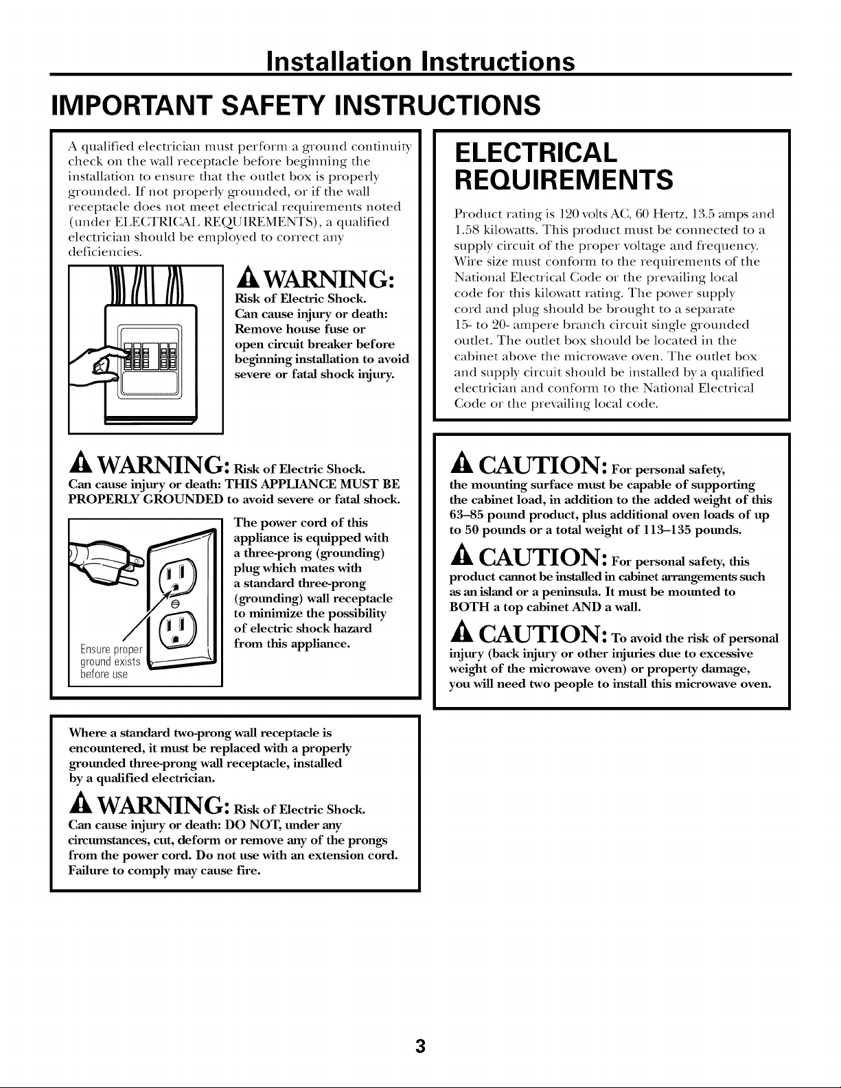
/k WARNING:
Risk of Electric Shock.
Can cause injury or death:
Remove house fuse or
open circuit breaker before
beginning installation to avoid
severe or fatal shock injury.
ik WARNING: RiskofElectricShock.
Can cause injury or death: THIS APPLIANCE MUST BE
PROPERLY GROUNDED to avoid severe or fatal shock.
The power cord of this
appliance is equipped with
a three-prong (grounding)
plug which mates with
a standard three-prong
(grounding) wall receptacle
to minimize the possibility
of electric shock hazard
Ensureproper
groundexists
beforeuse
from this appliance.
ELECTRICAL
REQUIREMENTS
Product ra6ng is 120 volts AC, 60 Hertz, 13.5 mnps and
1.58 kilowatts. This product nltlst be connected to a
supply circuit of the proper voltage and frequency.
Wire size must conform to the requirements of the
National Electrical (;ode or the prevailing local
code for this kilowatt ra6ng. The power supply
cord and plug should be brought to a separate
15- to 20- ampere branch circuit single grounded
outlet. The outlet box should be located in the
cabinet above the microwave oven. The outlet box
and supply circuit should be installed by a qualified
electrician and conform to the National Electrical
(;ode or the prevailing local code.
./k CAUTION: Forpersonal safety,
the mounting surface must be capable of supporting
the cabinet load, in addition to the added weight of this
63-85 pound product, plus additional oven loads of up
to 50 pounds or a total weight of 113-135 pounds.
_k CAUTION: Forpersonal safety, this
product cannot be installed in cabinet arrangements such
as an island or a peninsula. It must be mounted to
BOTH a top cabinet AND a wall.
_k CAUTION: Toavoidtheriskofpersonal
injury (back injury or other injuries due to excessive
weight of the microwave oven) or property damage,
you will need two people to install this microwave oven.
Where a standard two-prong wall receptacle is
encountered, it must be replaced with a properly
grounded three-prong wall receptacle, installed
by a qualified electrician.
/k WARNING: RiskofElectricShock.
Can cause injury or death: DO NOT, under any
circumstances, cut, deform or remove any of the prongs
from the power cord. Do not use with an extension cord.
Failure to comply may cause fire.
3
Page 4
Installation Instructions
HOOD EXHAUST
NOTE: Read these next two pages only if you plan to vent your exhaust to the
outside. If you plan to recirculate the air back into the room, proceed to page 6.
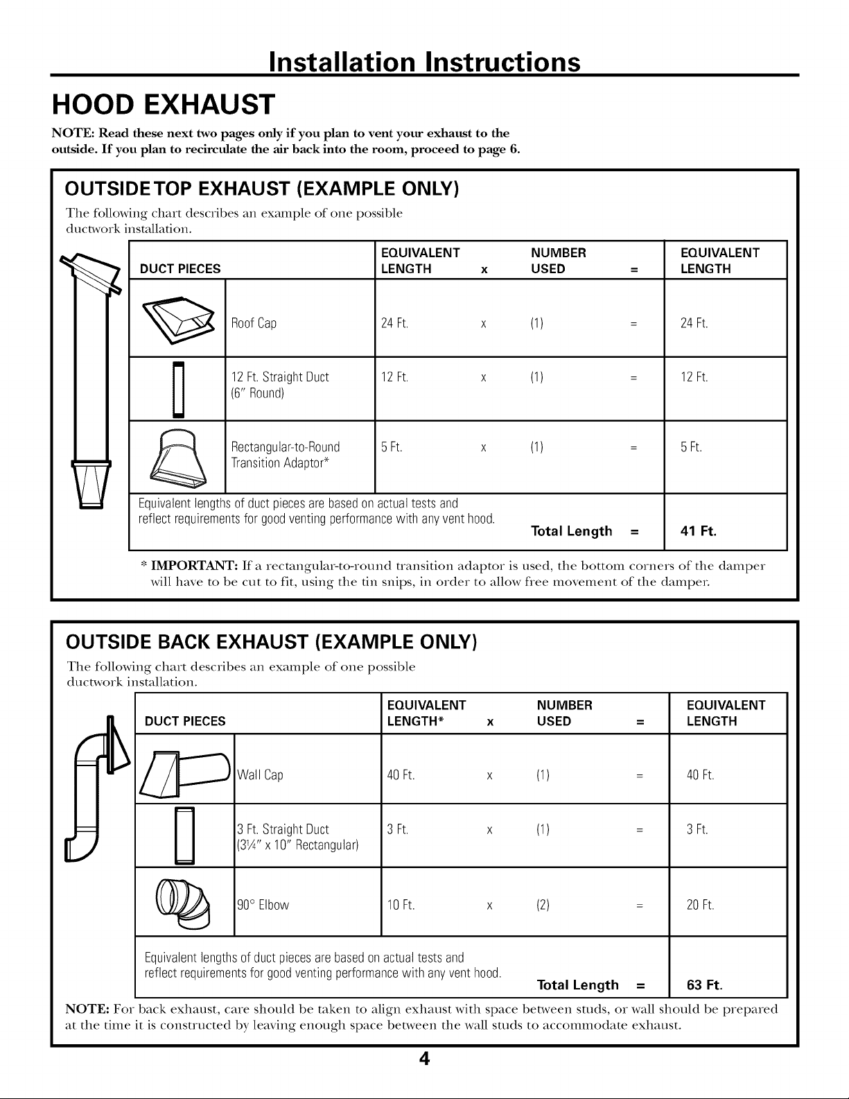
OUTSIDETOP EXHAUST (EXAMPLE ONLY)
The following chart describes an example of one possible
ductwork installation.
EQUIVALENT NUMBER EQUIVALENT
DUCT PIECES LENGTH x USED = LENGTH
12Ft.StraightDuct 12Ft. x
RoofCap 24Ft. x
(6" Round)
TransitionAdaptor*
Rectangular-to-Round 5 Ft. x
Equivalentlengthsof ductpiecesare basedon actualtests and
reflectrequirementsfor goodventingperformancewith anyventhood.
* IMPORTANT: If a rectangular-to-round transition adaptor is used, the bottom corners of the damper
will have to be cut to fit, using the tin snips, in order to allow free movement of the dampeL
OUTSIDE BACK EXHAUST (EXAMPLE ONLY)
The following chart describes an example of one possible
ductwork installation.
EQUIVALENT NUMBER
DUCT PIECES
LENGTH* x USED
(1)
(1)
(1)
Total Length =
24Ft.
12Ft.
5 Ft.
41 Ft.
EQUIVALENT
LENGTH
Wall Cap
3 Ft.StraightDuct
[
Equivalentlengthsof ductpiecesarebasedonactualtestsand
reflectrequirementsfor goodventingperformancewith anyvent hood.
NOTE: For back exhaust, care should be taken to align exhaust with space between studs, or wall should be prepared
at the time it is constructed by leaving enough space between the wall studs to accommodate exhaust.
3W'x 10" Rectangular)
90° Elbow
40Ft. x (1)
3 Ft. x (1)
10Ft. x (2)
Total Length = 63 Ft.
40 Ft.
3 Ft.
20Ft.
4
Page 5
Installation Instructions
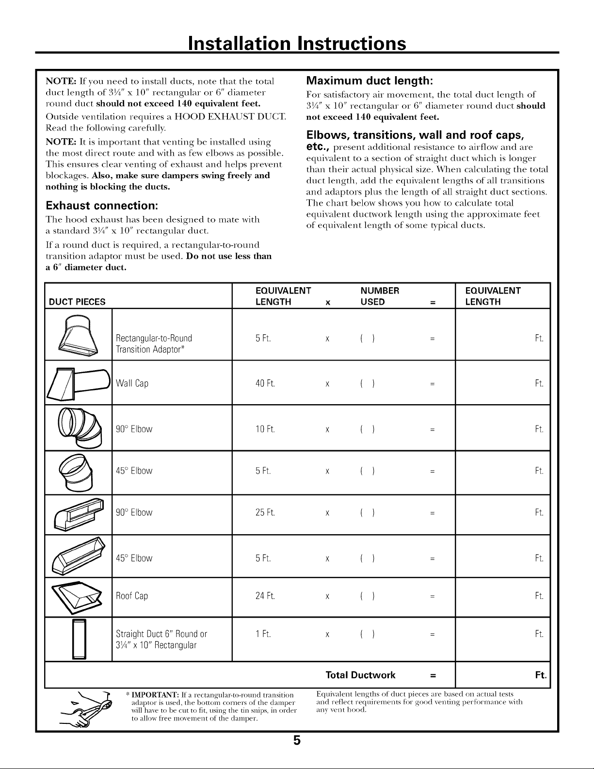
NOTE: If you need to install ducts, note that tile total
duct length of 3¼" x 10" rectangular or 6" diameter
round duct should not exceed 140 equivalent feet.
Outside ventilation requires a HOOD EXHAUST DUCT.
Read tile following carefllll>
NOTE: It is important that venting be installed using
tile most direct route and with as few elbows as possible.
This ensures clear venting of exhaust and helps prevent
blockages. Also, make sure dampers swing freely and
nothing is blocking the ducts.
Exhaust connection:
Tile hood exhaust has been designed to mate with
a standard 3¼" x 10" rectangular duct.
If a round duct is required, a recmngula>to-round
uansition adaptor must be used. Do not use less than
a 6" diameter duct.
EQUIVALENT
DUCT PIECES
Rectangular-to-Round
TransitionAdaptor*
LENGTH
5 Ft.
Maximum duct length:
For satisfactory' air movement, tile total duct length of
3¼" x 10" rectangular ov 6" diameter round duct should
not exceed 140 equivalent feet.
Elbows, transitions, wall and roof caps,
etc., present additional resistance to airflow and are
equivalent to a section of straight duct which is longer
than their actual physical size. When calculating tile total
duct length, add tile equivalent lengths of all transitions
and adaptors plus tile length of all straight duct sections.
Tile chart below shows you how to calculate total
equivalent ductwovk length using tile approximate feet
of equivalent length of some b'pical ducts.
NUMBER
X
USED
( )
EQUIVALENT
LENGTH
Ft.
O
J
Wall Cap
90° Elbow
45° Elbow
90° Elbow
45° Elbow
RoofCap
StraightDuct6" Roundor
31/4"x 10"Rectangular
40 Ft.
10Ft.
5 Ft.
25 Ft.
5 Ft.
24 Ft.
1Ft.
( )
( )
( )
( )
( )
( )
( )
Ft.
Ft.
Ft.
Ft.
Ft.
Ft.
Ft.
IMPORTANT: If a rectangula>to-round transition
adaptor is used, the bottom corners of the damper
will have to be cut to fit, using the tin snips, in order
to allow fi"ee movement of the damper.
Total Ductwork
Equivalent lengths of duct pieces are based on actual tests
and reflect requiren_ents for good venting perfbl-mance x_qth
;_I_) r veIlt hood.
5
Ft.
Page 6
Installation Instructions
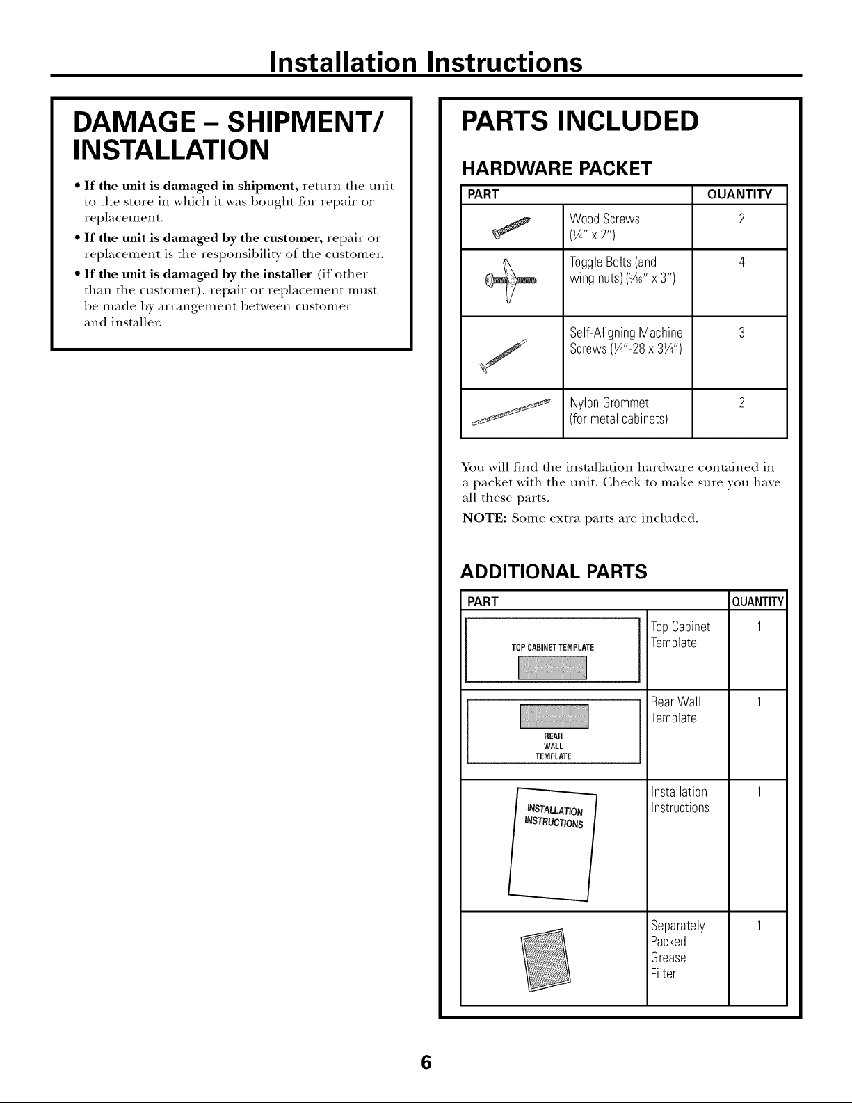
DAMAGE - SHIPMENT/
INSTALLATION
• If the unit is damaged in shipment, return the unit
to the store in which it was bought for repair or
replacement.
• If the unit is damaged by the customer, repair or
replacement is the responsibility of the customeL
• If the unit is damaged by the installer (if other
than the customer), repair or replacement must
be made by arrangement between customer
and insmlleL
PARTS INCLUDED
HARDWARE PACKET
PART
Wood Screws
(1/4"X2")
ToggleBolts(and
wing nuts)(s4¢'x 3")
Self-AligningMachine
Screws(1/4"-28x 31/4")
NylonGrommet
(formetalcabinets)
You will find the installation hardware contained in
a packet with the unit. Check to make sure you have
all these parts.
NOTE: Some exua parts are included.
QUANTITY
2
ADDITIONAL PARTS
PART
TOPCABINETTEMPLATE
REAR
WALL
TEMPLATE
_q
INSTRUCTIONS
TopCabinet
Template
RearWall
Template
Installation
Instructions
Separately
Packed
Grease
Filter
QUANTITY
1
6
Page 7
Installation Instructions
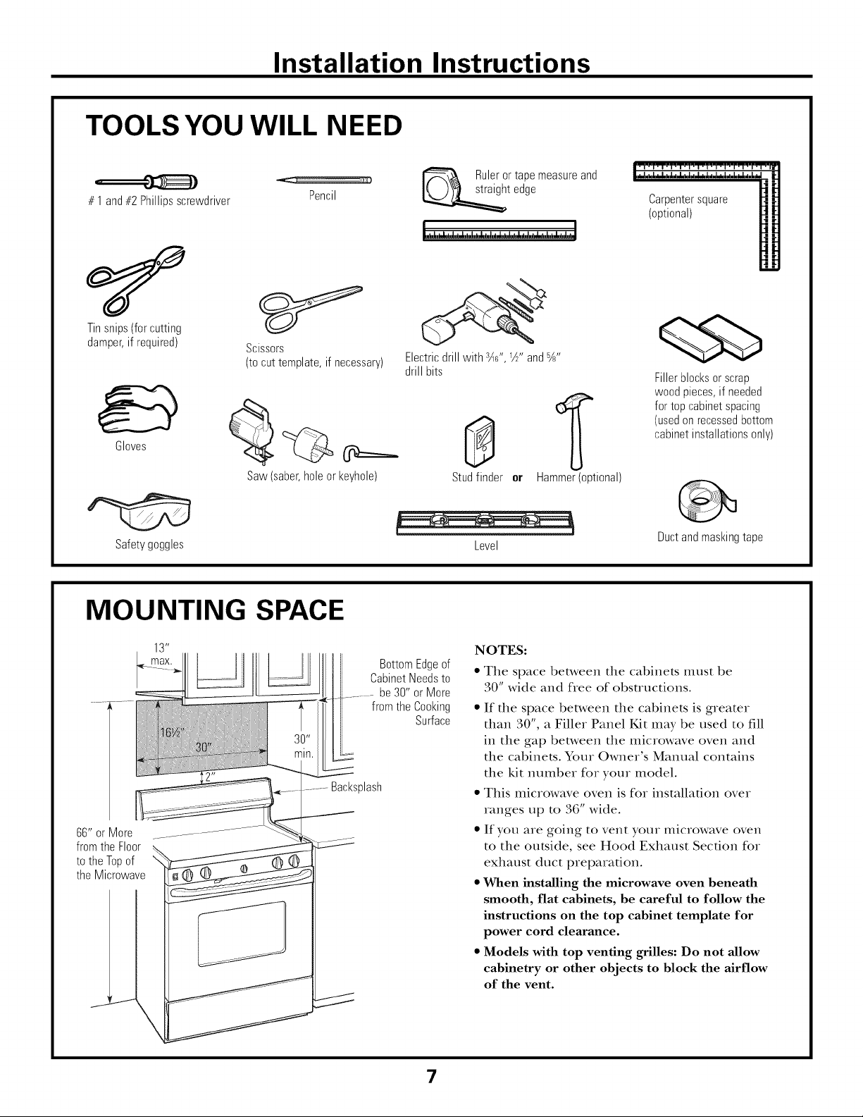
TOOLS YOU WILL NEED
# 1and#2Phillipsscrewdriver
Tinsnips(forcutting
damper,if required)
Gloves
Scissors
(tocut template,if necessary)
Saw(saber,holeor keyhole)
Pencil
Ruleror tapemeasureand
t edge
Electricdrill with r_c",W' and%"
drill bits
0
Studfinder or
Hammer(optional)
Carpentersquare
(optional)
Fillerblocksor scrap
woodpieces,if needed
fortop cabinetspacing
(usedonrecessedbottom
cabinetinstallationsonly)
Safetygoggles Level
MOUNTING SPACE
BottomEdgeof
CabinetNeedsto
be30" or More
from the Cooking
Backsplash
66" or More
fromthe Floor
tothe Topof
the Microwave
Surface
Ductandmaskingtape
NOTES:
• The space between the cabinets must be
30" wide and flee of obstructions.
• If the space between the cabinets is greater
than 30", a Filler Panel Kit may be used to fill
in the gap between the microwave oven and
the cabinets. Your Owner's Manual contains
the kit number for your model.
• This microwave oven is for installation over
ranges up to 36" wide.
• If you are going to vent your microwave oven
to the outside, see Hood Exhaust Section for
exhaust duct preparation.
• When installing the microwave oven beneath
smooth, flat cabinets, be careful to follow the
instructions on the top cabinet template for
power cord clearance.
• Models with top venting grilles: Do not allow
cabinetry or other objects to block the airflow
of the vent.
\
7
Page 8
Installation Instructions
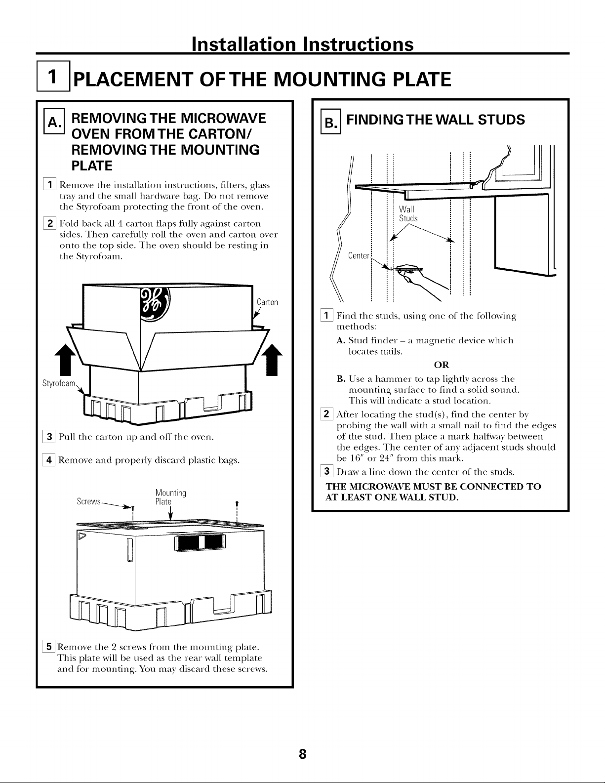
PLACEMENT OF THE MOUNTING PLATE
A-_ EMOVING THE MICROWAVE
OVEN FROM THE CARTON/
REMOVING THE MOUNTING
PLATE
_i_ Remove the installation instructions, filters, glass
tray and the small hardware bag. Do not remove
the SDrofoam protecting the flont of the oven.
[] Fold back all 4 carton flaps fldly against carton
sides. Then careflflly roll the oven and carton over
onto the top side. The oven should be resting in
the St);rofoam.
[]Pull the carton up and off the oven.
[] Remove and properly discard plastic bags.
Mounting
Plate
_] FINDING THE WALL STUDS
Wall
' ill
Studs
[]Find the studs, using one of the following
methods:
A. Stud finder - a magnetic device which
locates nails.
OR
B. Use a hammer to mp lightly across the
mounting surface to find a solid sound.
This will indicate a stud location.
After locating the stud(s), find the center by
probing the wall with a small nail to find the edges
of the stud. Then place a mark halfivay between
the edges. The center of any adjacent studs should
be 16" or 24" flom this mark.
]Draw a line down the center of the studs.
THE MICROWAVE MUST BE CONNECTED TO
AT LEAST ONE WALL STUD.
[]Remove the 2 screws flom the mounting plate.
This plate will be used as the rear wall template
and for mounting. You may discard these screws.
8
Page 9
Installation Instructions
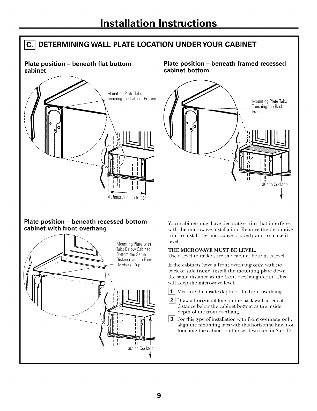
I-_ DETERMINING WALL PLATE LOCATION UNDER YOUR CABINET
Plate position - beneath flat bottom
cabinet
MountingPlateTabs
oO
",,%
%.
At least 30", up to 36"
the CabinetBottom
Plate position - beneath framed recessed
cabinet bottom
MountingPlateTabs
Touchingthe Back
Frame
30" to Cooktop
Plate position - beneath recessed bottom
cabinet with front overhang
MountingPlatewith
TabsBelow Cabinet
BottomtheSame
Distanceas the Front
OverhangDepth
i II
i II
30" to Cooktop
Your cabinets may have decorative trim that interferes
with the microwave installation. Remove the decorative
trim to install the microwave properly and to make it
level.
THE MICROWAVE MUST BE LEVEL.
Use a level to make sure the cabinet bottom is level.
If the cabinets have a flont overhang only, with no
back or side frame, install the mounting plate down
the same distance as the flont overhang depth. This
will keep the microwave level.
[]Measure the inside depth of the flont overhang.
_] Draw a horizontal line on the back wall an equal
distance below the c;d)inet bottom as the inside
depth of the flont overhang.
_]For this type of installation with flont overhang only,
align the mounting robs with this horizontal line, not
touching the ctd)inet bottom as described in Step D.
9
Page 10
Installation Instructions
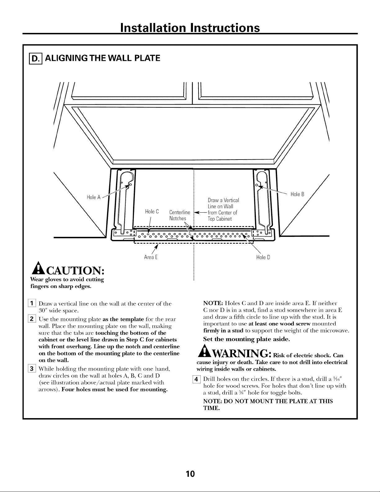
I-_ ALIGNING THE WALL PLATE
HoleC Centerline
Notches
HoleB
Drawa Vertical
LineonWall
._-_- fromCenterof
TopCabinet
ooooooo
o oooooooo
/
AreaE
CAUTION:
Wear gloves to avoid cutting
fingers on sharp edges.
[]Draw a vertical line on the wall at the center of the
30" wide space.
[]Use the mounting plate as the template for the rear
wall. Place the mounting plato on the wall, making
sure that the robs are touching the bottom of the
cabinet or the level line drawn in Step C for cabinets
with front overhang. Line up the notch and centerline
on the bottom of the mounting plate to the centerline
on the wall.
[] While holding tim mounting plate with one hand,
draw circles on the wall at holes A, B, C and D
(see illusuation above/actual plate marked with
arrows). Four holes must be used for mounting.
HoleD
NOTE: Holes C and D are inside area E. If neifller
C nor D is in a stud, find a stud somewhere in area E
and draw a fifth circle m line up with the stud. It is
important to use at least one wood screw mounted
firmly in a stud m support the weight of the microwave.
Set the mounting plate aside.
WARNING: ruskofelectricshock.Can
cause injury or death. Take care to not drill into electrical
wiring inside walls or cabinets.
[] Drill holes on die circles. If there is a stud, drill a :X_"
hole for wood screws. For holes that don't line up with
a stud, drill a %" hole for toggle bolts.
NOTE: DO NOT MOUNT THE PLATE AT THIS
TIME.
10
Page 11

Installation Instructions
INSTALLATION TYPES
This microwave oven is designed for adaptauon to
the following three types of ventilation:
A. Outside Top Exhaust (Vertical Duet)
B. Outside Back Exhaust (Horizontal Duet)
C. Redreulating (Non-Vented Ductless)
OUTSIDE TOP EXHAUST
(VERTICAL DUCT)
Adaptorin Placefor
/
OutsideTopExhaust
(Choose A, B or C)
NOTE: This microwave is shipped assembled for Outside
Top Exhaust (except for non-vented models). Select the
type of ventilation required for your installation and
proceed to that section.
OUTSIDE BACK EXHAUST
(HORIZONTAL DUCT)
[_ RECIRCULATING
(NON-VENTED DUCTLESS)
11
A Gharcoal Filter Accessory
Kit is required for the non-
vented exhaust. (See your
Owner's Manual for the kit
ntl IllbeI.)
Page 12
Installation Instructions
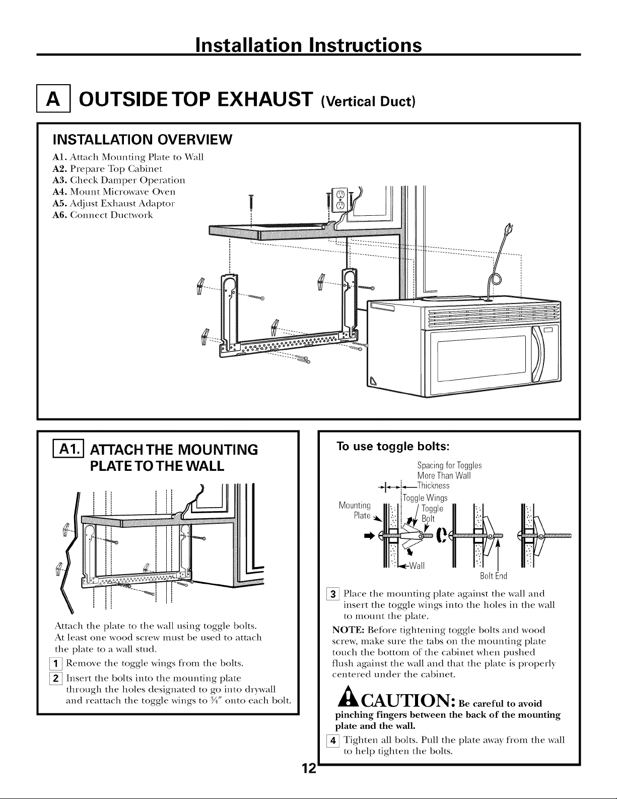
OUTSIDE TOP EXHAUST (Vertical Duct)
INSTALLATION OVERVIEW
A1. Attach Mounting Plate to Wall
A2. Prepare Top Cabinet
A3. Check Damper Operation
A4. Mount Microwave Oven
A5. Adjust Exhaust Adaptor
A6. Gonnect Ductwork
|
I-_ ATrACH THE MOUNTING
PLATE TO THE WALL
II
Attach tim plate to tim wall using toggle bolts.
At least one wood screw illust be used to attach
the plate to a wall stud.
[]Remove the toggle wings flom the bolts.
[]Insert the bolts into the mounting plate
through the holes designated to go into drDvall
and reatmch the toggle wings to :_" onto each bolt.
===m
To use toggle bolts:
Spacingfor Toggles
MoreThanWall
_,-_[_Thickness
Mounting
Plate
_ Place tim mounting plate against tim wall and
insert tim toggle wings into tim holes in tim wall
to i_lotlnt the plate.
NOTE: Before tightening toggle bolts and wood
screw, make sure tim robs on the mounting plate
touch the bottom of the cabinet when pushed
flush against the wall and that the plate is properly
centered under the cabinet.
ToggleWings
BoltEnd
A
• lkCAUTION: Be careful to avoid
pinching fingers between the back of the mounting
plate and the wall.
_ Tighten all bolts. Pull the plate away flom the wall
to help tighten tim bolts.
12
Page 13
Installation Instructions
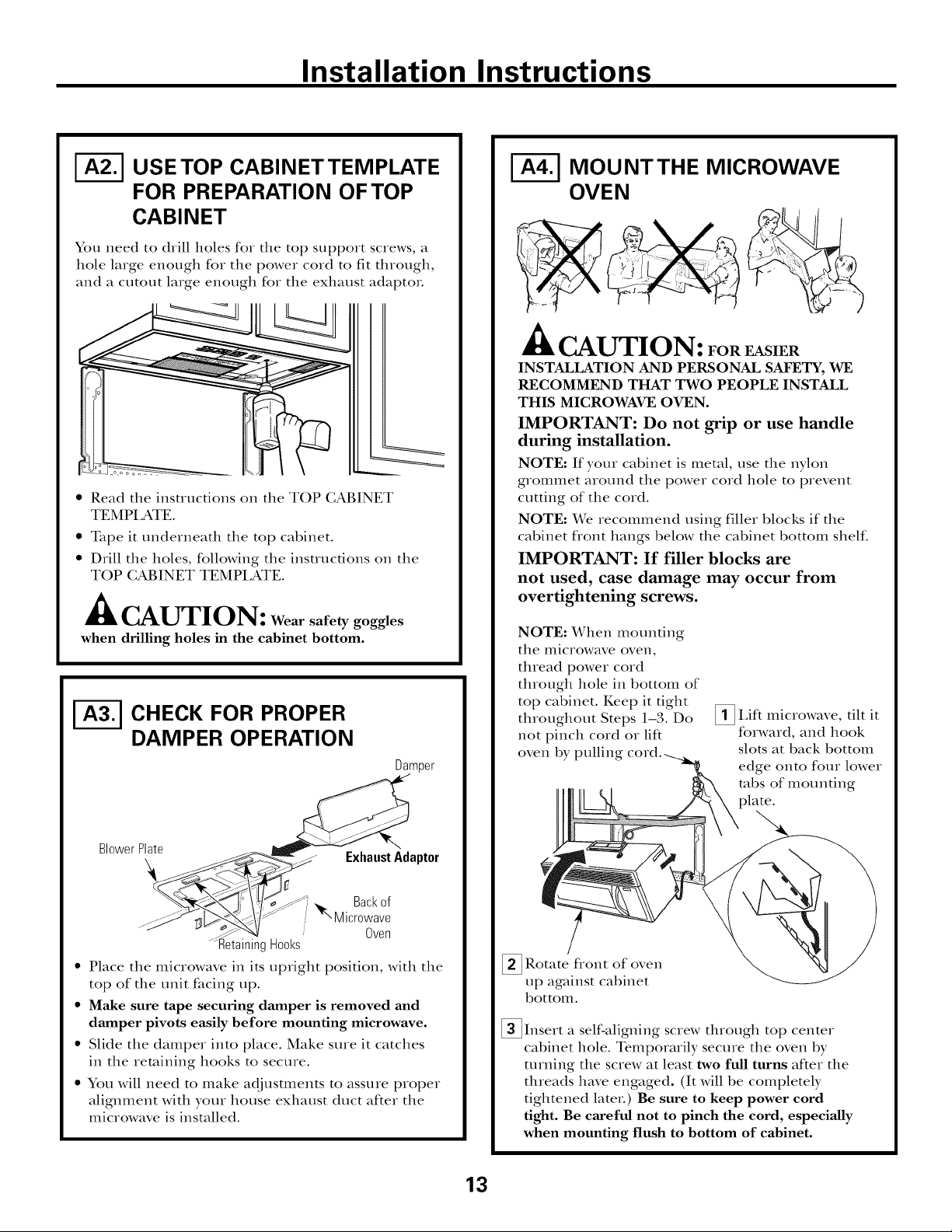
USE TOP CABINETTEMPLATE
FOR PREPARATION OF TOP
CABINET
You need to drill holes for tile top support screws, a
hole large enough for tile power cord to fit through,
and a cutout large enough for tile exhaust adaptor.
%
• Read tile insuuctions on tile TOP CABINET
TEMPI ,ATE.
• Tape it tmderneath tile top cabinet.
• Drill tile holes, following tile instructions on tile
TOP (;ABINET TEMPI,ATE.
CAUTION: Wear safety goggles
when drilling holes in the cabinet bottom.
CHECK FOR PROPER
DAMPER OPERATION
Damper
MOUNTTHE MICROWAVE
OVEN
CAUTION: FoREnSIER
INSTALLATION AND PERSONAL SAFETY, WE
RECOMMEND THAT TWO PEOPLE INSTAI_J_
THIS MICROWAVE OVEN.
IMPORTANT: Do not grip or use handle
during installation.
NOTE: If your cabinet is metal, use tile nylon
grommet around tile power cord hole to prevent
cutting of tile cord.
NOTE: We recommend using fillet blocks if the
cabinet flont hangs below tile cabinet bottom shehc.
IMPORTANT: If filler blocks are
not used, case damage may occur from
overtightening screws.
NOTE: When mounting
tile illiciox, vave oven,
thread power cord
through hole in bottom of
top cabinet. Keep it tight
throughout Steps 1-3. Do
not pinch cord or lift
oven by pulling
_!_ IAft tilt it
microwave,
forward, and hook
slots at back bottom
edge onto four lower
robs of mounting
BlowerP_e _. ExhaustAdaptor
.... NI_Microwave
...-_ . . Oven
• Place tile microwave in its upright position, with tile
top of tile unit facing up.
• Make sure tape securing damper is removed and
damper pivots easily before mounting microwave.
• Slide tile damper into place. Make sure it catches
in tile retaining hooks to secure.
• You will need to make adjustments to assure proper
alignment with your house exhaust duct after tile
microwave is installed.
_ Rotate fiont of
up against cabinet
bottom.
_Insert a self-aligning screw through top center
cabinet hole. Temporarily secure the oven by
turning tile screw at least two full turns after tile
threads have engaged. (It will be completely
tightened later.) Be sure to keep power cord
tight. Be careful not to pinch the cord, especially
when mounting flush to bottom of cabinet.
oven
13
Page 14
Installation Instructions
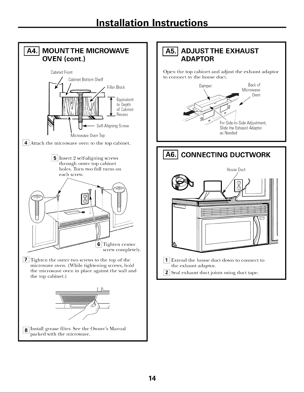
MOUNTTHE MICROWAVE
OVEN (cont.)
CabinetFront
CabinetBottomShelf
FillerBlock
to Depth
ofCabinet
"_ Equivalent
Recess
Self-AligningScrew
MicrowaveOvenTop
_ Attach the microwave oven to the top cabinet.
[] Insert 2 self-aligning screws
through outer top cabinet
holes. Turn two full ttlIns on
each screw.
ADJUSTTHE EXHAUST
ADAPTOR
Open the top cabinet and adjust the exhaust adaptor
to connect to the house duct.
Damper Backof
Microwave
Oven
" _djustment
Slidethe ExhaustAdaptor
asNeeded
CONNECTING DUCTWORK
HouseDuct
Tighten center
screw completely.
[] Tighten the outer two screws to the top of the
microwave oven. (While tightening screws, hold
the microwave oven in place against the wall and
the top cabinet.)
I I_L--
[] Install grease filter. See the Owner's Manual
packed with the microwave.
_1_ Extend the house duct down to connect to
the exhaust adaptoi.
[] Seal exhaust duct joints using duct rope.
14
Page 15
Installation Instructions
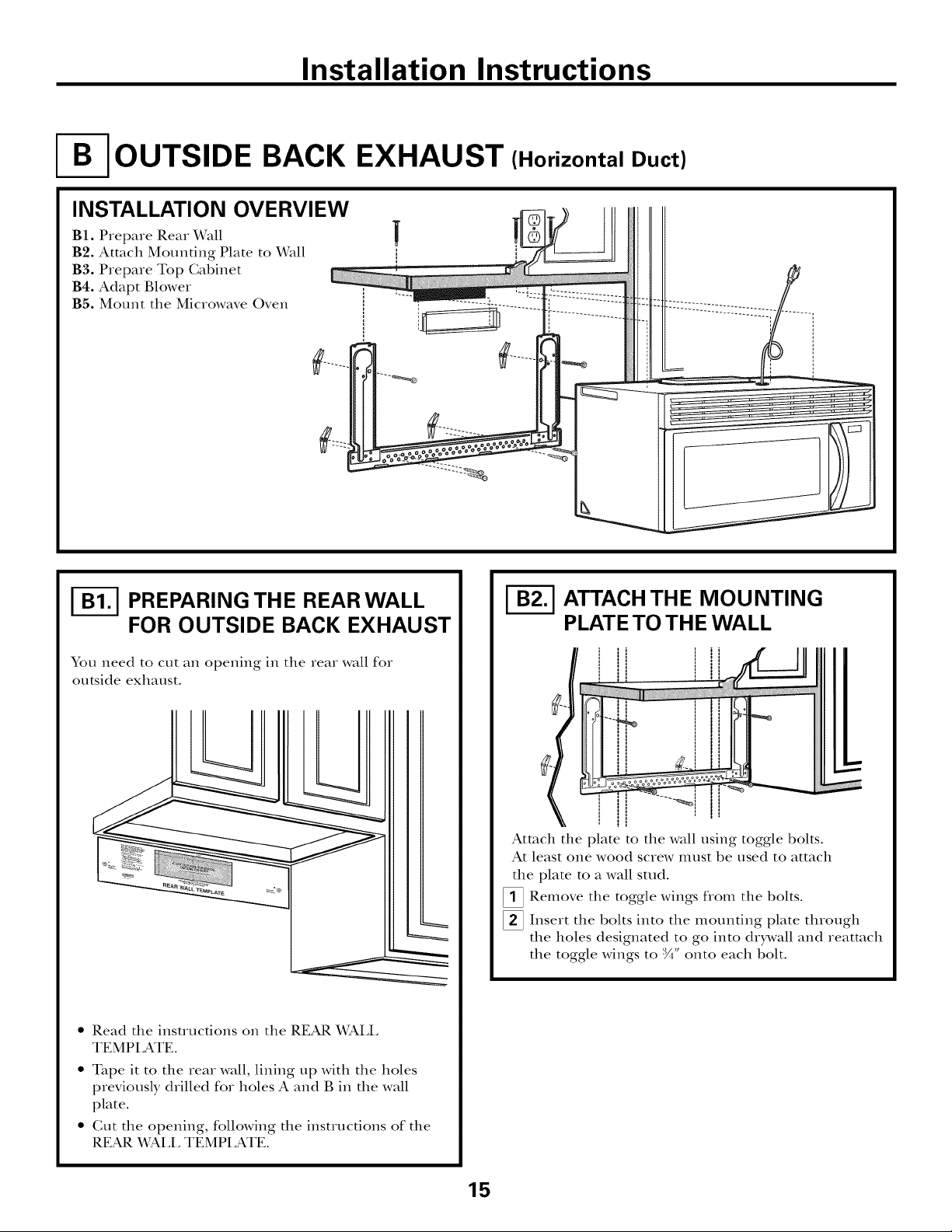
OUTSIDE BACK EXHAUST (Horizontal Duct)
INSTALLATION OVERVIEW
B1. Prepme Rear Wall
B2. Attach Mounting Plate to Dvrall
B3. Prepare Top Gabinet
B4. Adapt Blower
B5. Mount the Mic_owave Oven
I-_ PREPARING THE REAR WALL
FOR OUTSIDE BACK EXHAUST
You need to cut an opening in the rea_ wall fo_
outside exhaust.
• Read the instructions on the REAR WALL
TEMPLATE.
• Tape it to the Iea_ wall, lining up with the holes
previously d_illed fo_ holes A and B in the wall
plate.
• Gut the opening, following the instructions of the
REAR V_Pd.L TEMPLATE.
I-_ ATTACH THE MOUNTING
PLATE TO THE WALL
Attach the plate to the wall using toggle bolts.
At least one wood scIew Illust be used to attach
the plate to a wall stud.
_ Remove the toggle wings flom the bolts.
_ Inse_t the bolts into the mounting plate through
the holes designated to go into drDvall and _eatmch
the toggle wings to :_" onto each bolt.
15
Page 16

Installation Instructions
To use toggle bolts:
+l_-,_i*_ ThanWall Thickness
i
Mounting
Plate
[]Place the mounting plate against tile wall and
insert the toggle wings into tlle holes in tile wall
tO II1Otlll[ tile plate.
NOTE: Before tightening toggle bolts and wood
screw, make sure the tabs on the mounting plate
touch the bottom of tile cabinet when pushed flush
against the wall and ttlat tim plate is properly
centered under tile cabinet.
Spacingfor TogglesMore
ToggleWings
BoltEnd
CAUTION" Becarefulto avoid
pinching fingers between the back of the mounting
plate and the wall.
[]Tighten all bolts. Pull the plate away from the wall
to help tighten the bolts.
ADAPTING MICROWAVE
BLOWER FOR OUTSIDE
BACK EXHAUST
_;!_ Remove and the that holds the blower
inotor door closed on the back and the blower
retaining screw on the top of the dooL
Blower--a,,_
Retaining :_ BI0wer
Screw_..
save screw
....
Backof Screw
Microwave
Oven
_Open the blower door it tim backby lifting
of the microwave oven. Remove and save the
blower retaining screw.
DoorRetaining
at
tip
I-_ USETOP CABINETTEMPLATE
FOR PREPARATION OF TOP
CABINET
You need to drill holes for the top support screws and
a hole large enough for the power cord to fit ttlrough.
• Read the instructions on the TOP CABINET
TEMPI ,ATE.
• Tape it underneath the top cabinet.
• Drill the holes, following the instructions on the
TOP CABINET TEMPI,ATE.
CAUTION: Wearsafety goggles when
drilling holes in the cabinet bottom.
/i>-f-/
[ Careflflly the blower unit. The wirespull
will extend far enough to allow you to adjust the
blower unit.
EndA
otlt
"_r--...._ BlowerRetaining
Screw
EndB
16
Page 17

Installation Instructions
ADAPTING MICROWAVE
BLOWER FOR OUTSIDE
BACK EXHAUST (cont.)
_ Rotate blower unit counterclockwise 180 °.
BeforeRotation After Rotation
Microwave Microwave
Oven Oven
[Gently' the wires flom the
Reroute the wires through grooves on other side
of the blower unit.
ienlove
BeforeRerouting After Rerouting
grooves.
[]Place the blower unit back into the opening.
EndA
End
A
CAUTION: Donot pull or
stretch the blower unit wiring. Make sure the
wires are not pinched.
NOTE: The blower unit exhaust
openings should match exhaust
openings on rear of microwave oven.
[ Secure the blower to the microwave oven
using the retaining screw flom Step 2.
_ Blower
WiresRoutedThroughRightSide WiresRoutedThroughLeft Side
[]Roll the blower unit 90 ° so that fan blade
openings are facing out the back of the
microwave.
BeforeRolling
Microwave
Oven
After Rolling
_ Backof
Microwave
Oven
Backof RetainingScrew
Microwave
Oven
%
Slide the exhaust adaptor onto tim back
of the microwave oven, securing it into the
lower locking robs. Take care to ensure that
the damper hinge is installed so that it is at
the top and that the damper swings fleely.
Reinstall the upper blower motor screw
through the adaptor and tim blower door
and into the back of the microwave oven.
Close the blower door and secure it using
the screw flom Step 1.
Blower-------a_ Backof
etaining __;;-- MicrowaveOven
crew __-__
Guide _!_ _"_"_-_.._ _ Blower Motor
Adaptor LockingTabs DoorRetaining
(notshown) Screw
17
Page 18

Installation Instructions
I-_ MOUNTTHE MICROWAVE
OVEN
CAUTION: FOREASIER
INSTALLATION AND PERSONAL SAFETY, WE
RECOMMEND THAT TWO PEOPLE INSTALL
THIS MICROWAVE OVEN.
IMPORTANT: Do not grip or use handle
during installation.
NOTE: If your cabinet is metal, use tim nylon
grommet around tim power cord hole to prevent
cutting of tim cord.
NOTE: We recommend using filler blocks if the
cabinet flont hangs below the cabinet bottom shelf.
IMPORTANT: If filler blocks are
not used, case damage may occur from
overtightening screws.
NOTE: When mounting
the microwave oveIl,
thread power cord
through hole in bottom of
top cabinet. Keep it tight
throughout Steps 1-3. Do
not pinch cord or lift
oven by pulling cord.
[]I,ift microwave, tilt it
forward, and hook
slots at back bottom
edge onto four lower
tabs of mounting
plate.
CabinetFront
CabinetBottomShelf
FillerBlock
_ quivalent
to Depth
ofCabinet
Recess
Self-AligningScrew
MicrowaveOvenTop
_i_ Attach the microwave oven to the top cabinet.
_2 Insert 2 self-aligning screws
through outer top cabinet
holes. Turn two fldl turns oil
each screw.
Tighten center
screw completely.
[] Tighten the outer two screws to the top of the
microwave oven. (While tightening screws, hold
tim microwave oven in place against tim wall and
tim top cabinet.)
liL---
[]Rotate fiont of
up against cabinet
bottom.
[]Insert a self-aligning screw through top center
cabinet hole. Temporarily secure the oven by
turning tim screw at least two full turns after tim
threads have engaged. (It will be completely
tightened latex.) Be sure to keep power cord
tight. Be careful not to pinch the cord, especially
when mounting flush to bottom of cabinet.
ovexl
_ Install filteL See the Owner's Manual
grease
packed with tim microwave.
18
Page 19
Installation Instructions
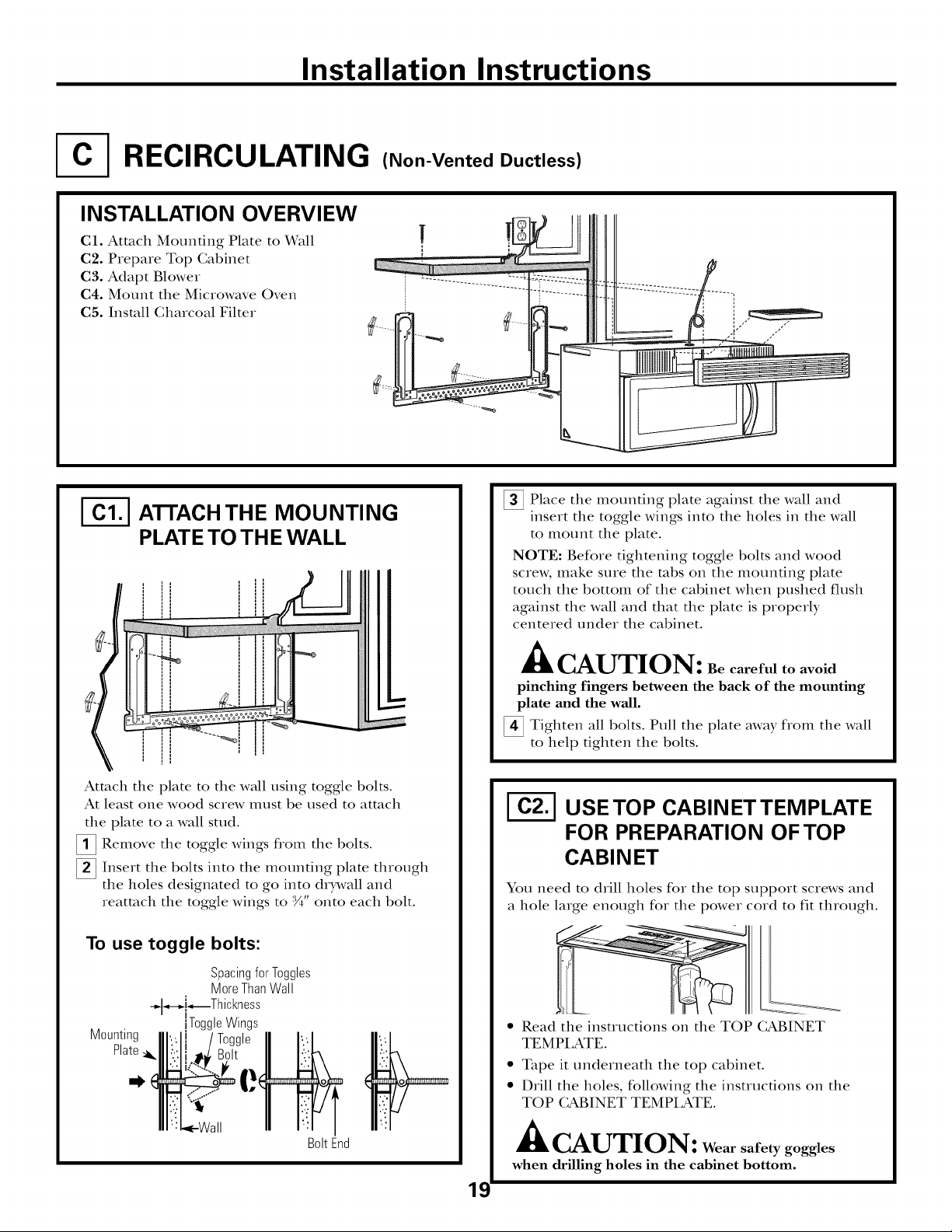
RECIRCULATING (Non-Vented Ductless)
INSTALLATION OVERVIEW
C1. Attach Mounting Plate to Wall
C2. Prepare Top Gabinet
C3. Adapt Blower
C4. Mount the Microwave Oven
C5. Install Gharcoal Filter
|
I_ A]-FACHTHE MOUNTING
PLATE TO THE WALL
I , I
!
#
f
===o
\
Attach the plate to the wall using toggle bolts.
At least one wood screw must be used to attach
the plate to a wall stud.
_ Remove the toggle wings fiom the bolts.
_ Insert tim bolts into the mounting plate through
the boles designated to go into drDvall and
reatmch the toggle wings to :_A"onto each bolt.
To use toggle bolts:
_ Place the mounting plate against the wall and
insert the toggle wings into the holes in the wall
to inount the plate.
NOTE: Before tightening toggle bolts and wood
screw, make sure the robs on the mounting plate
touch the bottom of the cabinet when pushed flush
against the wall and that the plate is properly
centered under the cabinet.
A
• kCAUTION: Becarefulto avoid
pinching fingers between the back of the mounting
plate and the wall.
_ Tighten all bolts. Pull the plate away flom the wall
to help tighten the bolts.
USE TOP CABINET TEMPLATE
FOR PREPARATION OF TOP
CABINET
You need to drill holes for the top support screws and
a hole large enough for the power cord to fit through.
Mounting
Plate_i_
Spacingfor Toggles
MoreThanWall
-,-l-.-_i_Thckness
ToggleWings
BoltEnd
• Read the instructions on the TOP (;ABINET
TEMPI_ATE.
• Tape it underneath the top cabinet.
• Drill the holes, following the instructions on the
TOP GABINET TEMPLATE.
• CAUTION: Wearsafety goggles
when drilling holes in the cabinet bottom.
19
Page 20
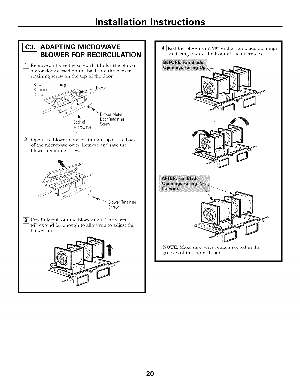
Installation Instructions
ADAPTING MICROWAVE
BLOWER FOR RECIRCULATION
_1_ Remove and the that holds the blower
motor door closed on the back and the blower
retaining screw on the top of the dooL
Blower--_
Retaining _.Blower
Screw
[]Open the blower door it the backby lifting up
of the microwave oven. Remove and save the
blower retaining screw.
save sciew
"\ DoorRetaining
Backof Screw
Microwave
Oven
BlowerMotor
a15
_Roll the blower unit 90 ° so that fan blade openings
are facing toward the flont of the microwave.
R011 4__I_
.... Blower Retaining
Screw
[] Garefully pull out the blower unit. The wires
will extend flu enough to allow you to adjust the
blower unit.
NOTE: Make sure wires remain routed in the
grooves of the motor flame.
20
Page 21

Installation Instructions
ADAPTING MICROWAVE
BLOWER FOR
RECIRCULATION (cont.)
[_ Place tile blower unit back into tile opening.
at
CAUTION: Donot pull or stretch
the blower unit wiring. Make sure the wires are
not pinched.
[]Close tile blower (loot. Secure tile blower
and blower (loot to tile microwave oven using
tile retaining screws fiom Steps 1 and 2.
Blower--------_$'
Retaining _ Blower
Screw_
%
___,<}7_ __'_*----BlowerMotorDoor
...._ _b_--_y 'i_<%r-._ RetainingScrew
_<__ _, -- Blower
Backof RetainingScrew
Microwave
Oven
MOUNTTHE MICROWAVE
OVEN
CAUTION: for EASIER
INSTALLATION AND PERSONAL SAFETY, WE
RECOMMEND THAT TWO PEOPLE INSTALL
THIS MICROWAVE OVEN.
IMPORTANT: Do not grip or use handle
during installation.
NOTE: If your cabinet is metal, use tile nylon
grommet around tile power cord hole to prevent
cutting of tile cord.
NOTE: We recommend using fillet blocks if the
cabinet fiont hangs below tile cabinet bottom shelf.
IMPORTANT: If filler blocks are not used,
case damage may occur from overtightening
screws.
NOTE: When mounting
tile microwave oven,
thread power cord
through hole in bottom of
top cabinet. Keep it tight
throughout Steps 1-3. Do
not pinch cord or lift
oven by pulling cord.
_Lifl microwave, tilt it
forward, and hook
slots at back bottom
edge onto four lower
tabs of mounting
)late.
/
_ Rotate flont of oven
up against cabinet
bottom.
21
Page 22
Installation Instructions
MOUNTTHE MICROWAVE
OVEN (cont.)
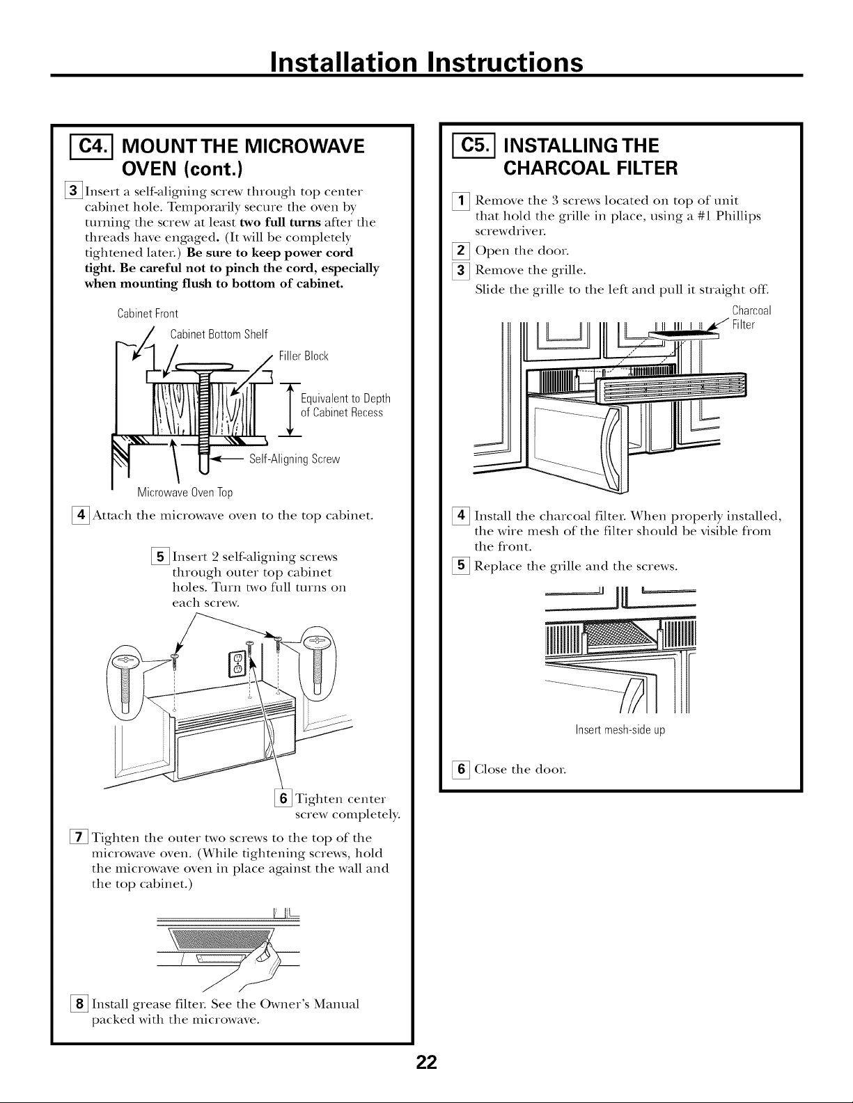
[]Insert a self-aligning screw through top center
cabinet hole. Temporarily secure the oven by
turning the screw at least two full turns after the
threads have engaged. (It will be completely
tightened later.) Be sure to keep power cord
tight. Be careful not to pinch the cord, especially
when mounting flush to bottom of cabinet.
CabinetFront
CabinetBottomShelf
FillerBlock
Equivalentto Depth
f CabinetRecess
Self-AligningScrew
MicrowaveOvenTop
[]Attach the microwave the cabinet.
[] Insert 2 self-aligning screws
through outer top cabinet
holes. Turn two flfll turns oil
each screw.
oven to
top
INSTALLING THE
CHARCOAL FILTER
_ Remove the 3 located of unit
that hold the grille in place, using a #1 Phillips
screwdriver.
_Open the door.
Remove the grille.
Slide the grille to the left and pull it straight off:
[] Install the charcoal filter. X&qmn properly
the wire mesh of the filter should be visible flom
the flont.
Replace the grille and the screws.
sciews oil
top
Charcoal
installed,
Tighten center
screw completely.
[] Tighten the outer two screws to the top of the
microwave oven. (While tightening screws, hold
the microwave oven in place against the wall and
the top cabinet.)
VI_L-
[] Install filteL See the Owner's Manual
grease
packed with the microwave.
Insertmesh-sideup
_ Glose the dooL
22
Page 23
Installation Instructions
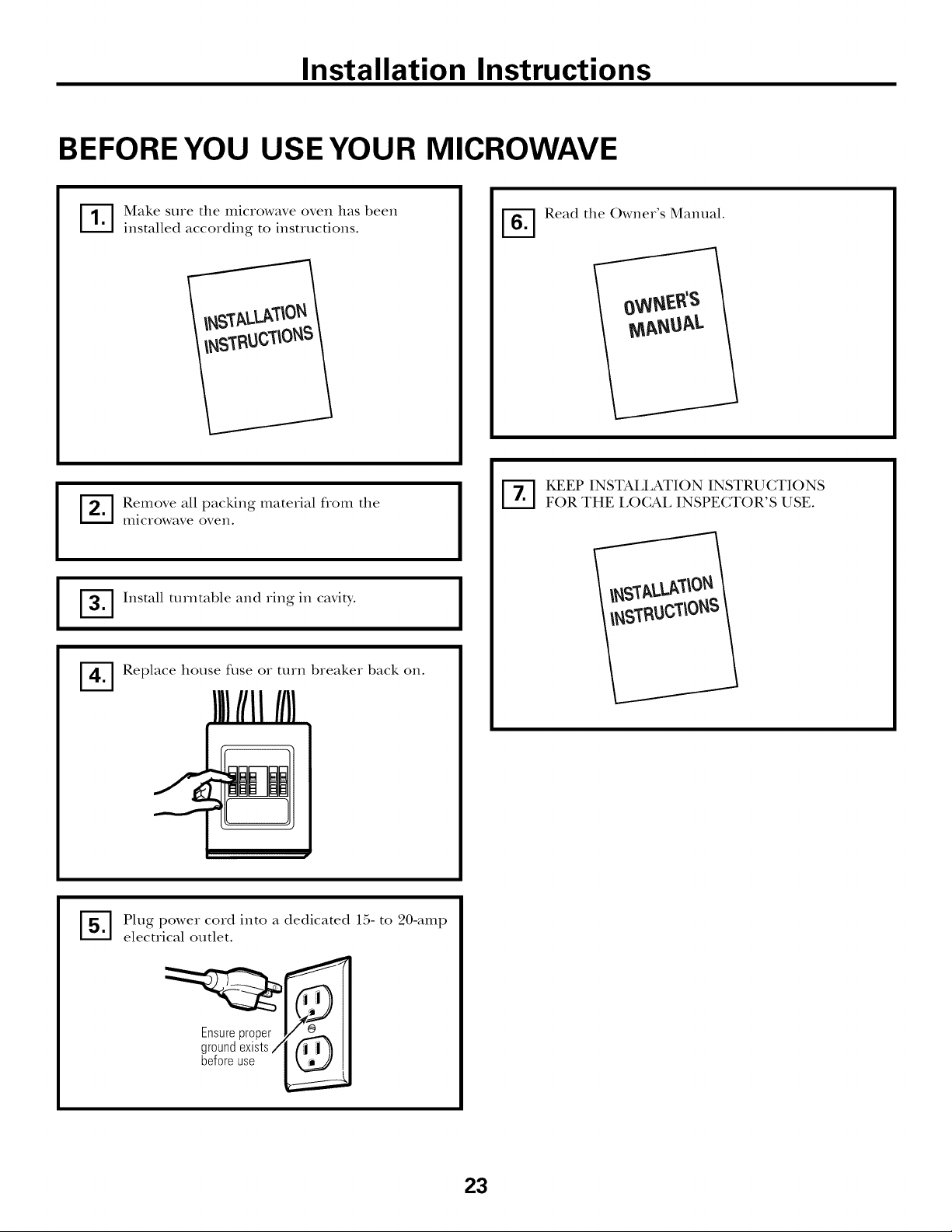
BEFORE YOU USE YOUR MICROWAVE
IT[ Make sure the microwave oven has been
installed according to instructions.
Remove all packing material flom the
microwave oven.
Install turntable and ring in cavity.
I
Replace house fllse or turn breaker back on.
I
'_] Read the Owner's Manual.
KEEP INSTALLATION INSTRUCTIONS
FOR THE LOCAL INSPECTOR'S USE.
Plug power cord into a dedicated 15- to 20-amp
%
electrical outlet.
i"
t
Ensureproper
groundexists/
beforeuse
i"
k.
23
Page 24

t DE68-03698A49-40615-1
09-09 JR Printed in Malaysia
Page 25
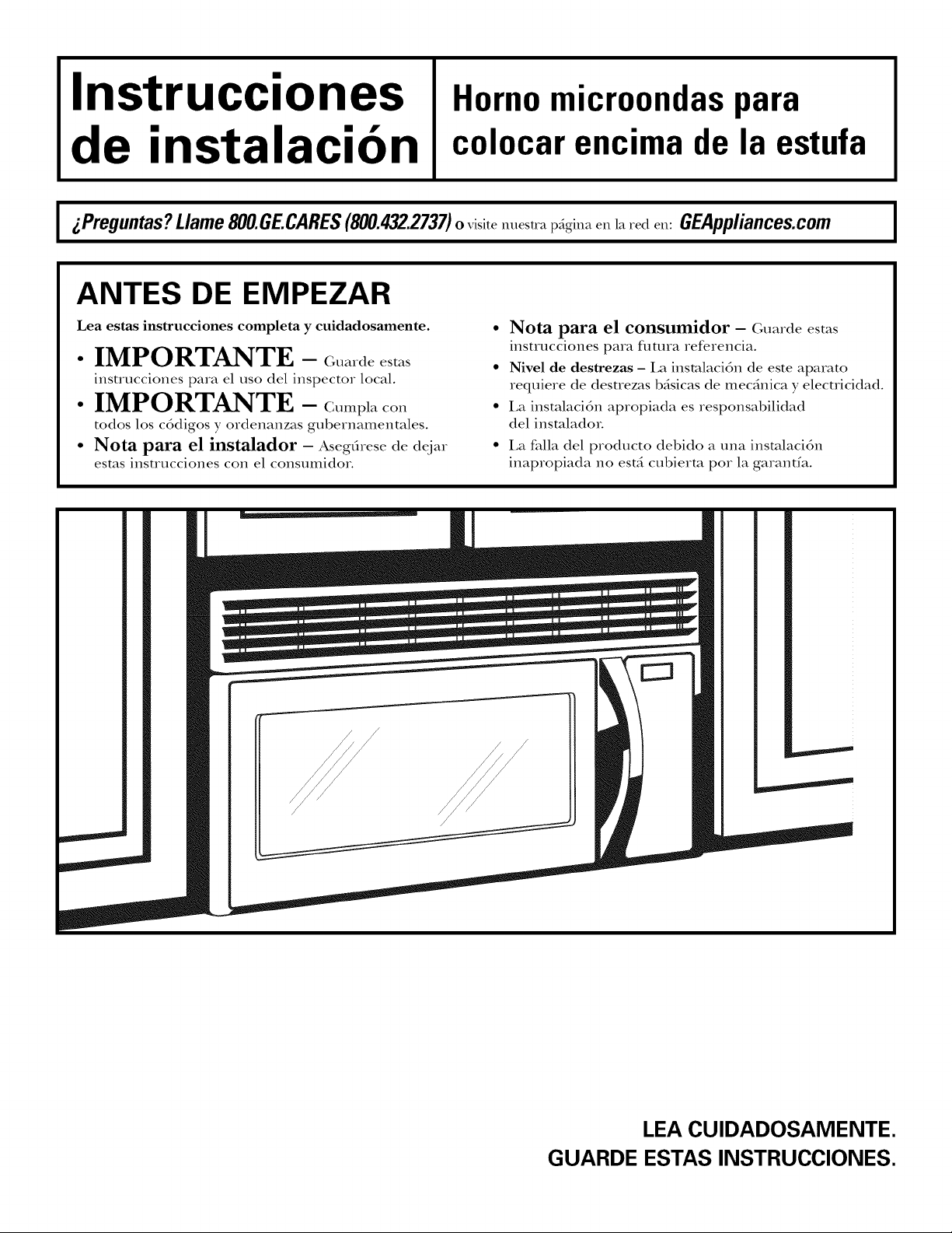
Instrucciones
Homo microondas para
de instalacion
gPreguntas? Llame800.GE.CARES(800.432.2737)o,_i_it_m,_t,ap_gina_n_a,'_d_n:GEAppliances.com I
colocar encima de la estufa
ANTES DE EMPEZAR
Lea estas instrucciones completa y cuidadosamente.
• IMPORTANTE - c_._1_e_
instrucciones para el uso del inspector local.
• IMPORTANTE - C.mpl_,co.
todos los cddigos y ordenanzas gubernamentales.
• Nota para el instalador - Asegfirese de deiar
estas instrucciones con el consumidor.
• Nota para el consumidor - Guarde esms
instrucciones para flmna referencia.
• Nivel de destrezas - La insmlacidn de este aparato
requieve de desuezas bdsicas de mecdnica y elecuicidad.
• La instalacidn apropiada es responsabilidad
del insmladoL
• La falla del pvoducto debido a una insmlacidn
inapvopiada no est_ cubievm pot la garantfa.
/
/
LEA CUlDADOSAMENTE.
GUARDE ESTAS INSTRUCCIONES.
Page 26

Instrucciones de instalacion
CONTENIDO
Informacion general
Instrucciones de seguridad importantes .................. 3
Requisitos el6ctricos ................................................ 3
Campana de escape .............................................. 4, 5
Dafios - Envio / Instalaci6n .................................... 6
Partes incluidas ........................................................ 6
Herramientas que necesitarfi .................................... 7
Espacio de montaje .................................................. 7
Guia de instalacion paso por paso
C6mo colocar el plato de montaje ...................... 8-10
C6mo remover el plato de mont_je ................ 8
C6mo encontrar los postes
de viga en la pared ........................................ 8
C6mo determinar la localizaci6n del plato
de mont_{je .................................................... 9
_ Recirculacidn ........................................ 19-22
Cdmo adherir el plato de mont_je
a la pared ............................................ 19
Cdmo preparar el gabinete superior ....19
Cdmo adaptor el calefactor del
microondas para la recirculacidn .... 20, 21
Cdmo monmr el homo
microondas ...................................... 21, 22
Cdmo insmlar el filtro de carbonilla....22
Antes de comenzar a usar su horno microondas .... 23
Cdmo alinear el plato de mont_je sobre
la pared ...................................................... 10
Tipos de instalaci6n .......................................... 11-22
_ Escape superior .......................
C6mo adherir el plato de mont_{je
a la pared ............................................ 12
C6mo preparar el gabinete superior....13
C6mo inspeccionar si la operaci6n
del regulador de tiro es apropiada ...... 13
Cdmo montar el homo
microondas .................................... 13, 14
C0mo t_iusmr el adapmdor de escape ....14
Cdmo conecmr el conducto ................ 14
_1_ Escape posterior externo ......................
C6mo preparar la pared posterior
para el escape posterior exterior ........ 15
C6mo adherir el plato de mont_je
a la pared ...................................... 15, 16
exterior.
12-14
15-18
C6mo preparar el gabinete superior....16
C6mo adaptar el calefactor
del microondas para el escape
posterior exterior. ........................... 16, 17
Cdmo montar el homo microondas .... 18
2
Page 27

Instrucciones de instalacion
INSTRUCCIONES DE SEGURIDAD IMPORTANTES
Un elecuicism calificado debe realizar una verificacidn
de continuidad de conexidn a tierra en el tomacorriente
de pared antes de comenzar la instalacidn para garantizar
que la c_tja de disuibucidn tenga una adecuada conexidn
a tierra. Si no cuenm con una adecuada conexi6n a
tierra, o si el tomacorriente de pared no cumple con
los requisitos el_ctricos indicados (b_tjo REQUISITOS
EI,EGTRI(;OS), debe conuamrse un elecuicism
calificado para corregir las deficiencias.
/k ADVERTENCIA:
Riesgo de descarga el6ctrica.
Puede provocar una lesi6n
o la muerte: Quite el fusible o el
interruptor de circuitos de la vivienda
antes de comenzar la instalaci6n para
evitar tma lesi6n por descarga grave
o fatal.
/k ADVERTENCIA: Riesgo de descarga
el6ctrica. Puede provocar una lesi6n o la muerte: ESTE
APARATO DEBE CONTAR CON UNA ADECUADA
CONEXION A TIERRA para evitar una descarga grave
o fatal.
El cable el6ctrico de este
aparato estfi equipado con
un enchufe de tres patas
(con conexi6n a tierra),
1o cual requiere que el
mismo encaje con un
tomacorriente para tres
patas (con conexirn a
Asegdresede
queexiste
unaconexi6natierra
apropiadaantesdel uso
tierra) de pared para
minimizar la posibilidad
de descargas elrctricas.
REQUISITOS
ELECTRICOS
La clasificacidn del producto es de 120 vatios (;A
(AC), 60 hertz, 13.5 amperios y 1.58 kilovatios. Este
producto debe esmr conectado a un circuito de
suministro del volt;tie y flecuencia apropiados. E1
mmafio del alambre debe conformarse a los requisitos
del National Elecuic Gode o al cddigo local en efecto
para este fndice de kilovatios. E1 cable el6ctrico de
alimenmcidn y el interruptor deber_n llevarse a un
tomacorriente dnico conecmdo a tierra de 15 a
20 amperios. La c_tja del tomacorriente deberd esmr
localizada en el gabinete encima del homo. La
c_Oadel tomacorriente debe sex instalada pox un
elecuicism calificado y debe conformarse al National
Elecuical Gode o al c6digo local en efecto.
PRECAUCION: Enposdela
seguridad personal, la superfide de montaje debe ser
capaz de soportar la carga del gabinete, ademas del
peso adicional (de 63 a 85 libras) de este producto,
mas las cargas adicionales del homo de hasta 50 libras
o un peso total entre 113 y 135 libras.
PRECAUCION: Euposaela
seguridad personal, este producto no puede ser
instalado en sistemas de gabinetes tales como los
Uamados "islas" o "peninsulas." Este debe ser montado
tanto a un gabinete superior como a una pared.
/k PRECAUCION: Para evitar el riesgo
de una lesi6n personal (en la espalda u otras lesiones
debido a peso excesivo del homo microondas) o dafios
a la propiedad, hacen falta dos personas para instalar
este homo microondas.
Donde haya tm tomacorriente de pared estfindar
de dos espigas, resulta indispensable cambiarlo por
un tomacorriente de pared de tres espigas con adecuada
conexi6n a tierra, instalado pot un electricista calificado.
/k ADVERTENCIA: mesgodedescarga
elrctrica. Puede provocar una lesi6n o la muerte: Bajo
NINGUNA circunstancia corte, deforme o quite las clavijas
del cable de energia. No utilice un cable de extensi6n.
No cumplir con esta indicaci6n puede provocar un
incendio.
3
Page 28

Instrucciones de instalacion
CAMPANA DE ESCAPE
NOTA: Lea las siguientes dos pfiginas solamente si planea ventilar el escape hacia el exterior.
Si pot el contrario planea recircular el aire de vuelta hacia el sal6n, continfie en la pfigina 6.
ESCAPE SUPERIOR EXTERNO (EJEMPLO SOLAMENTE)
La siguiente mbla describe un ejemplo de una posible
instalacidn de red de conductos.
LONGITUD NUMERO
PARTESDELCONDUCTO
Conductorectode 12pies
Tapadeltecho
(redondode 6")
derectanguloa redondo_
AdaptadordetransiciOn
LaIongitudde laspartesdelosconductosequivalentesestabasadaenpruebasrealesy reflejanlos
requisitosparaIograrunabuenaventilaciOnconcualquiercampanade escape.
* IMPORTANTE: Si se usa un adapmdor de transicidn de rectAngulo a redondo, las esquinas del rondo
del regulador de tiros deberfin cortarse para que encajen, usando las tijeras de corte, para permitir el
movimiento libre del regulador de tiros.
EQUIVALENTE x USADO
24pies x (1)
12pies x (1)
5 pies x (1)
Longitud total =
ESCAPE POSTERIOR EXTERNO (EJEMPLO SOLAMENTE)
LONGITUD
EQUlVALENTE
24pies
12pies
5 pies
41 pies
La siguiente tabla describe un ejemplo de una posible
insmlacidn de red de conductos.
LONGITOD NOMERO
PARTESDELCONDUCTO
Tapade pared 40pies x (1)
Conductorectode3 pies
(rectangularde31/4"x 10")
Cododeg0°
LaIongituddelaspartesde losconductosequivalentesestabasadaenpruebasrealesyreflejanlos
requisitosparaIograrunabuenaventilaciOnconcualquiercampanadeescape.
NOTA: Para el escape posterior; se debe tenet cuidado al alinear el escape entre los espacios de los postes de viga de la pared, o la pared deber/a
set preparada en el momento de su construccidn dejando suficiente espacio entre los postes de viga de la pared para acomodar el escape.
EQUIVALENTE x USADO
3 pies x (1)
10pies x (2)
kongitud total =
LONGITUD
EQUlVALENTE
40pies
3 pies
20pies
63 pies
4
Page 29

Instrucciones de instalacion
NOTA: Si usted necesim insmlar conductos, tenga
pendiente que la longimd tot;d del conducto rectangular
de 3¼" x 10" o el conducto redondo de 6" de diAmetro
no debe sobrepasar 140 pies equivalentes.
I;_ venfilaci6n externa requiere un CONDUCTO DE
CAMPANA DE ES(EAPE. I,ea lo siguiente cuidadosamente.
NOTA: Es impormnte que la venfilaci6n sea instalada
usando la rata m_isdirecta y'con la menor canfidad de
codos posible. Esto asegura la venfilacidn del escape y
ayuda a prevenir bloqueos. Tambi6n, eereidrese de que
el regulador de tiro pende libremente y nada bloquea
los conductos.
Conexiones de escape:
I;_ campana de escape ha sido diseflada pare enc_jar
con un conducto rectangular de 3¼"x 10" est;indaL
Si un conducto redondo es necesafio, se debe usar un
adapmdor de transicidn de rectangular a redondo.
No use un conducto menor de 6" de di£metro.
LONGITUD
PARTES DE CONDUCTO
AdaptadordetransiciOnde
rectanguloa redondo_
EQUlVALENTE
5 pies
Longitud maxima del conducto:
Para lograr un movimiento satisfactorio del aire, la
longimd total del conducto rectangular de 3¼" x 10"
o el conducto redondo de 6" de didmetro no debe
sobrepasar 140 pies equivalentes.
Los codos, transiciones, paredes y tapas
de techo, etc., presenmn resistencia adicional al
flt{jo de aire y son equivalentes a una seccidn de
conducto recto el cual es mils largo que su mmaflo ffsico
real. Cuando calcule la longimd total del conducto,
agregue las longitudes equivalentes de todas las
uansiciones y adaptadores, mils la longimd de todas
las secciones de conducto rectus. La tabla mils adelante
muesua cdmo puede calcular la longimd aproximada
de la red de conductos usando pies aproximados de
longitudes equivalentes de algunos conductos tfpicos.
NUNIERO
USADO
( )
LONGITUD
EQUlVALENTE
pies
J
Tapadepared
Cododeg0°
Codode45°
Cododeg0°
Codode45°
Tapadetecho
Conductorectode 6" redondo
m
m
orectangularde3W' x 10"
40 pies
10pies
5 pies
25 pies
5 pies
24pies
1pies
( )
( )
( )
( )
( )
( )
( )
pies
pies
pies
pies
pies
pies
pies
Total red de conductos = pies
transicidn de recttingulo a redondo, las esquinas del en pruebas reales y refleian los requisitos para lograr tma buem_
tondo del regulador de tiros deberfin set cortadas ;rentilaci6n con cualquier campana de escape.
* IMPORTANTF: Si se usa tm adaptador de La longitud de las partes de conductos e( uivalentes est5 basada
para que enc_jen, usando las tijeras de corte, para
permitir el moximiento libre del regulador de tiros.
5
Page 30

Instrucciones de instalacion
DAI_OS - ENVJO /
INSTALACION
• Si la unidad se dafia durante el envio, devuelva
la unidad al almac&l donde la adquiri6 para
su reparacidn o reemplazo.
• Si el diente dafia la unidad, la reparacidn o el
reemplazo es responsabilidad del clieme.
• Si el instalador dafia la unidad (si no es el clieme),
la reparacidn o reemplazo se debe hacer pot
medio de un arreglo entre el clieme y el insmladoL
PARTES INCLUIDAS
PAQUETE DE ELEMENTOS
PARTE
Tornillos de madera
(1/4"x2")
Tornillos basculantes
(ytuercas de mariposa)
(1/4"X3")
Tornillosdemaquina
autoalineables
(Y4"-28x 31/4")
Arandelaaislantede
nilOn(paragabinetes
metNicos)
Usted enconuard los elementos de insmlacidn en
un paquetejunto con la unidad. Inspeccione para
cerciorarse de que tiene todas las partes.
NOTA: Se incluyen algunas partes adicionales.
CANTIDAD
2
PARTES ADICIONALES
PARTE
TOPCABINETTEMPLATE
REAR
WALL
TEMPLATE
iNSTRUCTiONS
!
Plantillapara
el gabinete
superior
Plantillapara
lapared
posterior
Instrucciones
de instalaci0n
Filtrode
grasa
empacados
porseparado
CANTIDAD
1
6
Page 31

Instrucciones de instalacion
HERRAMIENTAS QUE NECESITARA
Destornilladoresdeestrella
#1y#2
Tijerasparacortarlat6n
(paracortarel regulador
detiro,si esnecesario)
Guantes
Gafasdeseguridad
L@iz
Tijeras(paracortarla
plantilla,si esnecesario)
Sierra(desable,agujero,ode
ojodecerradura)
recta y cinta m6trica
Taladroel6ctricoconbrocasde
3Z_,,,l/2,,ySA,,
8
Detectorde
postesdeviga e unmartillo(opcional)
Nivel
Escuadrade
carpintero
(opcional)
Bloquesde rellenoo
pedazosdemadera,si son
necesariospararellenarel
gabinete(usadosselamente
enla instalaci6nde
gabinetesapoyados)
Cintadeconductoso
cintaadhesivaprotectora
ESPACIO DE MONTAJE
13"
" 30" o m_sa partir
de salpicaduras
66" o mas [
desdeel /
pisohasta [
la parte |
ShUoPre;i°r
r
Elextremodel
fondodel gabinete
necesitaestar a
de la superficiede
laestufa
posterior
NOTAS:
• E1 espacio enue los gabinetes debe set de 30"
de ancho y debe estar libre de obstrucciones.
• Si el espacio entre los gabinetes es mayor de
30'_ un "Filler Panel Kit" podrfa sex necesario
para rellenar las brechas enue el homo y los
gabinetes. Su Manual del Propiemrio contiene
el nfimero de kit para su modelo.
• Este homo microondas es para sex instalado pox
encima de esmfas hasm 36" de ancho.
• Si usted se dispone a ventilar su homo
microondas hacia el exteriox; vex la Secci6n de
Gampana de Escape para la preparaci6n del
conducto de escape.
• Cuando se instale el horno mieroondas debajo
de gabinetes de rondos lisos y pianos, tenga
cuidado de seguir euidadosamente las
instruedones en la plantilla del gabinete superior
para el espacio de toleraneia del cable el_etrieo.
• Modelos con ventilaci6n superior: No permite
que los gabinetes u otros objetos obstruyan
el flujo de aire del ventilador.
7
Page 32
Instrucciones de instalacion
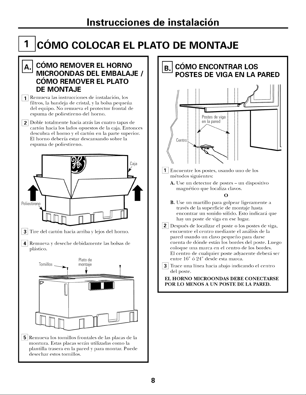
[ C6MO COLOCAR EL PLATO DE MONTAJE
A-I] C01VIO REMOVER EL HORNO
MICROONDAS DEL EMBALAJE /
C01VIO REMOVER EL PLATO
DE MONTAJE
Remueva las instFucciones de insmlacidn, los
%
filuos, la bandeja de crisml, y la bolsa pequefia
del equipo. No xemueva el protector flonml de
espuma de poliestireno del homo.
Doble tomlmente hacia auds las cuauo tapas de
[]
cartdn hacia los lados opuestos de la c_ja. Entonces
descubra el boxno y el cartdn en la parte superiox.
E1 homo deberfa esmr descansando sobre la
espuma de poliestireno.
Poliestireno
[] Tire del cart6n hacia arriba y lejos del homo.
[] Remueva y deseche debidamente las bolsas de
pl_istico.
Tornillos
Platode
montaje
_ C01VIOENCONTRAR LOS
POSTES DE VIGA EN LA PARED
l i
Postes de vlga i
enlapared i
i
Cent_°i_i
_i_ Encuentre los postes, usando uno de los
m_todos siguientes:
A. Use un detector de postes- un dispositivo
magn_tico que localiza clavos.
O
B. Use un maxdllo para golpear ligeramente a
uav_s de la superficie de mont_je hasta
enconuar un sonido sdlido. Esto indicard que
hay un poste de riga en ese lugaL
Despu_s de localizar el poste o los postes de viga,
encuenue el centto mediante el an_ilisis de la
pared usando un clavo pequeflo para darse
cuenta de ddnde est_hl los boxdes del poste. Luego
coloque una maxca en el cenuo de los boxdes.
E1 centro de cualquier poste adyacente deberd sex
enue 16" 6 24" desde esta marca.
Trace una lfnea hacia ab_jo indicando el
del poste.
EL HORNO MICROONDAS DEBE CONECTARSE
POR LO MENOS A UN POSTE DE LA PARED.
cexltxo
[] Remueva los tornillos flonmles de las placas de la
montma. Estas placas sexdn utilizadas como la
plantilla trasera en la pared y para montax. Puede
desechax estos toxnillos.
8
Page 33
Instrucciones de instalacion
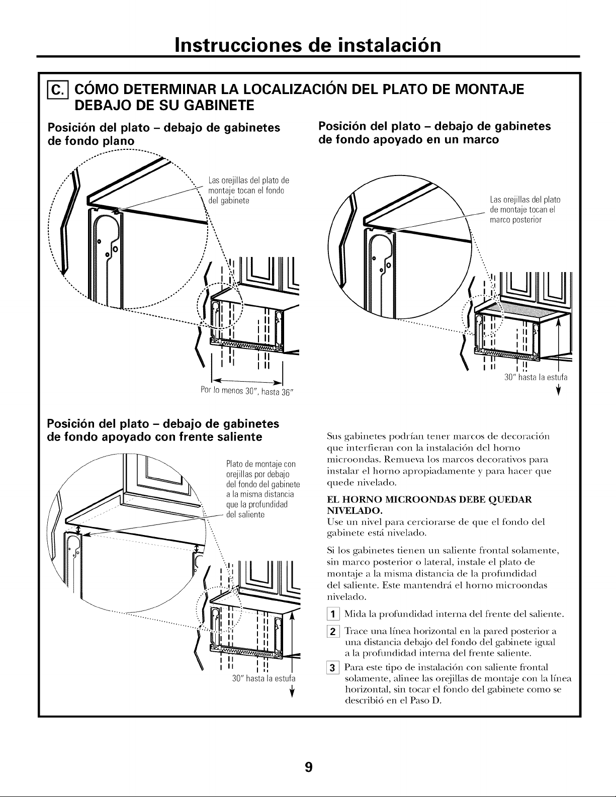
_-] C01VIO DETERMINAR LA LOCALIZACION DEL PLATO DE MONTAJE
DEBAJO DE SU GABINETE
Posicion del plato - debajo de gabinetes
de fondo piano
.°
oO
/ \del gabinete
%,
"',, Lasorejillasdelplatode
_ montajetocanelfondo
:\
; \
/
o*
,o
o,
.,
ooO°
Posicion del plato - debajo de gabinetes
de fondo apoyado en un marco
Lasorejillasdelplato
demontajetocanel
marcoposterior
II
30" hasta la estufa
Posicion del plato - debajo de gabinetes
de fondo apoyado con frente saliente
Plato de montaje con
orejillaspordebajo
del fondo del gabinete
alamismadistancia
quelaprofundidad
delsaliente
..
.
..
i II
i II
30" hasta la estufa
Sus gabinetes podrfan tenet marcos de decoracidn
que interfieran con la insmlacidn del homo
microondas. Remueva los marcos decorativos para
instalar el homo apropiadamente y para hacer que
quede nivelado.
EL HORNO MICROONDAS DEBE QUEDAR
NIVELADO.
Use un nivel para cerciorarse de que el fondo del
gabinete est_i nivelado.
Si los gabinetes tienen un saliente flontal solamente,
sin marco posterior o lateral, insmle el plato de
montaje a la misma dismncia de la proflmdidad
del saliente. Este mantendrg el homo microondas
nivelado.
[] Mida la profundidad interna del flente del saliente.
_] Trace una lfnea horizontal en la pared posterior a
una dismncia deb_jo del fondo del gabinem igual
a la profundidad interna del ffente saliente.
_] Para este tipo de insmlacidn con saliente frontal
solamente, alinee las orejillas de mont_je con la lfnea
horizontal, sin tocar el rondo del gabinete como se
describi6 en el Paso D.
9
Page 34
Instrucciones de instalacion
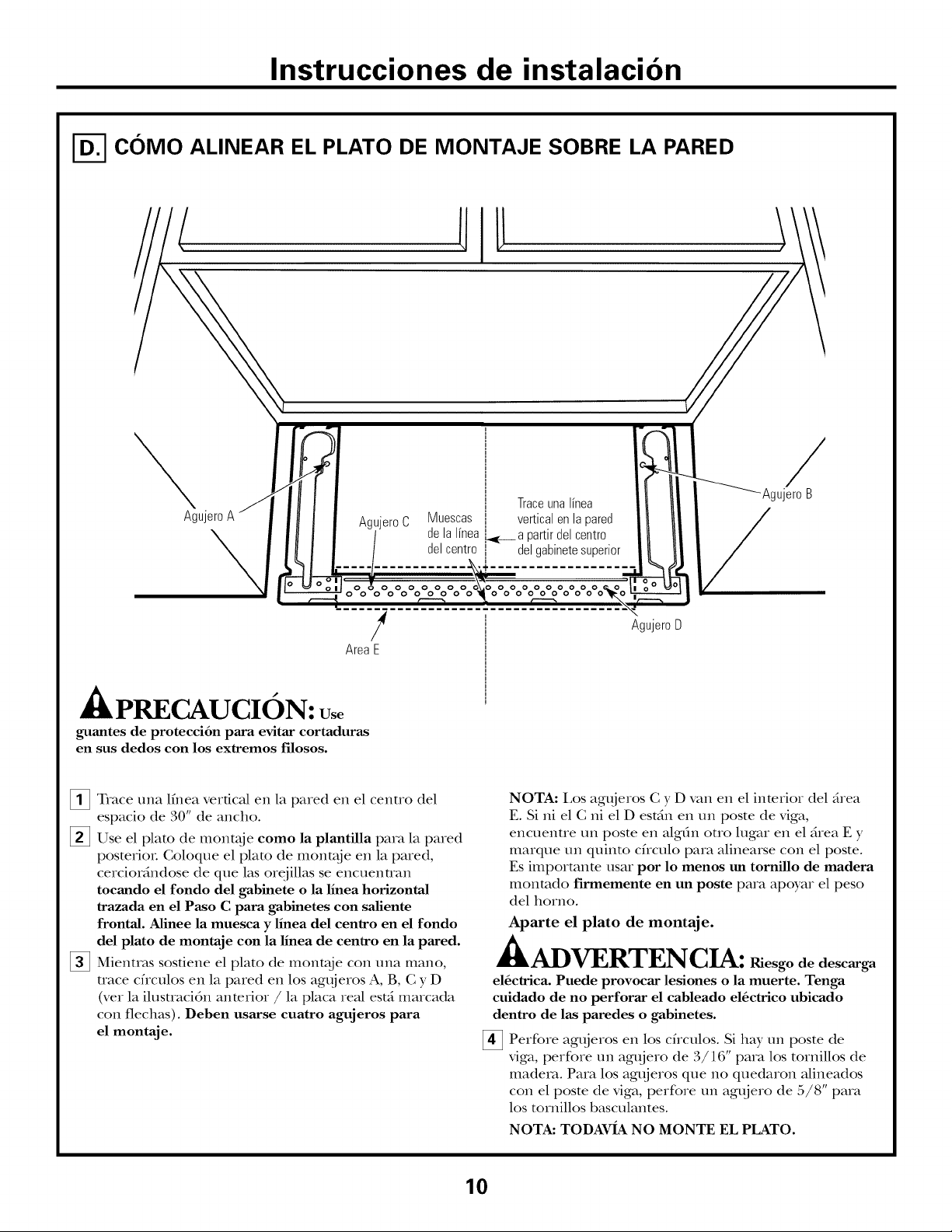
C01VIO ALINEAR EL PLATO DE MONTAJE SOBRE LA PARED
i
I
I
I
I
I
I
I
I
I
AgujeroA
Agujero C
Muescas I vertical en la pared
delalineai apartirdelcentro
del centro delgabinete superior
i Trace una linea
/
AgujeroB
000000
0 0000000
!
AreaE
APRECAUCION:
guantes de protecci6n para evitar cortaduras
en sus dedos con los extremos filosos.
_!_ Trace una lfnea vertical en la pared en el centro del
espacio de 30" de ancho.
[] Use el plato de mont;_je eomo la plantilla para la pared
posterioL Coloque el plato de mont;_je en la pared,
cercioMndose de que las orejillas se encuenuan
toeando el fondo del gabinete o la linea horizontal
trazada en el Paso C para gabinetes con saliente
frontal. Alinee la muesea y linea del eentro en el rondo
del plato de montaje con la linea de eentro en la pared.
[] Mientras sostiene el plato de mont;_je con una mano,
uace cficulos en la pared en los agt{jeros A, B, C y D
(vet la ilusuaci6n anterior / la placa real estfi marcada
con flechas). Deben usarse euatro agujeros para
el montaje.
0000000
00000000
AgujeroD
NOTA: I,os agt{jeros C y D van en el interior del drea
E. Si ni el C ni el D estdn en un poste de viga,
encuenue un poste en algfin oUo lugar en el _rea E y
marque un quinto chculo para alinearse con el poste.
Es impormnm usar por 1o menos un torniUo de madera
monmdo firmemente en un poste para apoyar el peso
del homo.
Aparte el plato de montaje.
it
-£kADVERTENCIA: Riesgo de descarga
el6ctrica. Puede provocar lesiones o la muerte. Tenga
cuidado de no perforar el cableado el6ctrico ubicado
dentro de las paredes o gabinetes.
Perfore agt_jeros en los chculos. Si hay un poste de
riga, perfore un agt{jero de 3/16" para los tornillos de
madera. Para los agt{jeros que no quedaron alineados
con el poste de viga, perfore un agt{jero de 5/8" para
los tornillos basculantes.
NOTA: TODAVIA NO MONTE EL PLATO.
10
Page 35
Instrucciones de instalacion
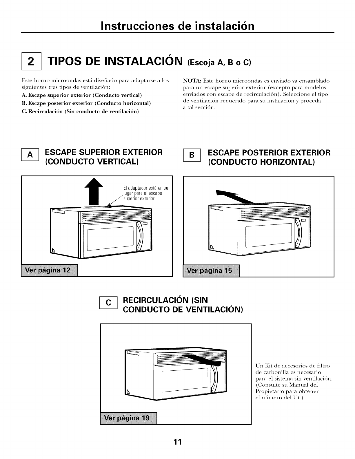
TIPOS DE INSTALACION (Escoja A, B o C)
Este homo microondas estd disefiado para adapmrse a los
siguientes nes tipos de ventilacidn:
A. Escape superior exterior (Condueto vertical)
B. Escape posterior exterior (Condueto horizontal)
C. Recirculaci6n (Sin conducto de ventilaci6n)
-_ ESCAPE SUPERIOR EXTERIOR
(CONDUCTO VERTICAL)
Eladaptadorest_ensu
superiorexterior
el escape
NOTA: Este horno microondas es enviado ya ensamblado
para un escape superior exterior (excepto para modelos
enviados con escape de recirculaci6n). Seleccione el tipo
de ventilacidn requerido para su insmlacidn y proceda
a ml seccidn.
ESCAPE POSTERIOR EXTERIOR
(CONDUCTO HORIZONTAL)
_ RECIRCULACl0N (SIN
CONDUCTO DE VENTILACION)
11
Un Kit de accesorios de filuo
de cm%onilla es necesario
para el sistema sin ventilacidn.
(Gonsulte su Manual del
Propietafio para obtener
el nOmero del kit.)
Page 36
Instrucciones de instalacion
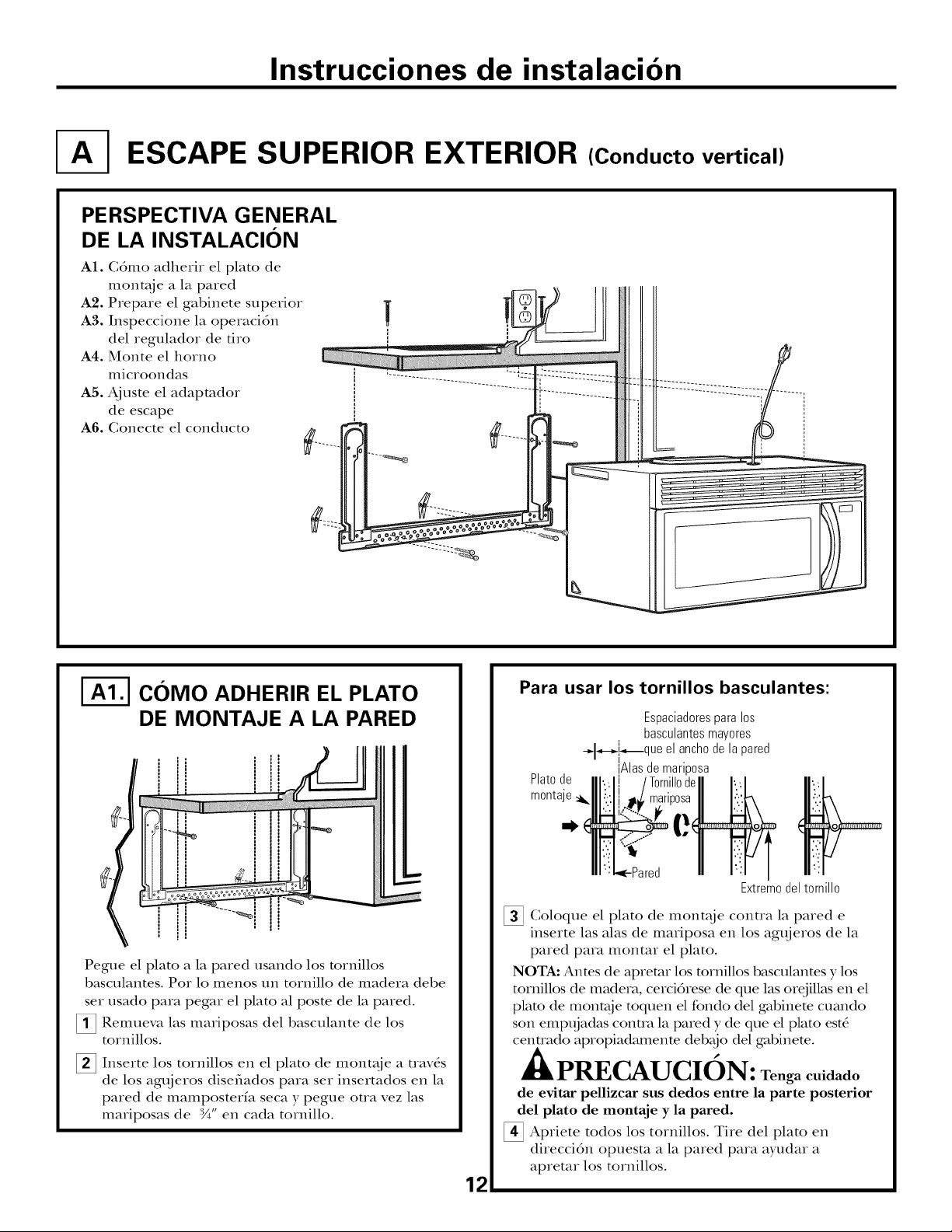
ESCAPE SUPERIOR EXTERIOR (Conducto vertical)
PERSPECTIVA GENERAL
DE LA INSTALACION
A1. Gdmo adherir el plato de
mont;{je a la pared
A2. Prepare el gabinete superior
A3. Inspeccione la operacidn
del regulador de tiro
A4. Monte el horno
microondas
A5. Ajuste el adapmdor
de escape
A6. Gonecte el conducto
|
I-_ COMO ADHERIR EL PLATO
DE MONTAJE A LA PARED
Pegue el plato a la pared usando los mrnillos
basculantes. Pot lo menos un tornillo de madera debe
set usado para pegar el plato al poste de la pared.
Remueva las mariposas del basculante de los
tornillos.
_2_ Inserte los tornillos en el plato de mont_je a uav_s
de los agt{jeros disefiados para set insertados en la
pared de mamposterfa seca y pegue oua vez las
mariposas de :W' en cada tornillo.
Para usar los tornillos basculantes:
Espaciadores para los
basculantes mayores
_a_,-_[_que el ancho de la pared
Platode
rnonta
Goloque el plato de mont_je contra la pared e
inserte las alas de mariposa en los agt{jeros de la
pared para montar el plato.
NOTA: Anms de apremr los mrnillos basculanms y los
tornillos de madera, cercidrese de que las orejillas en el
plato de mont;_je toquen el fondo del gabinete cuando
son empt{jadas conm_ la pared y de que el plato est_
centrado apropiadamente deb_jo del gabinete.
[Alas de mariposa
•Pared
PRECAUCION: Tenga cuidado
de evitar pellizcar sus dedos entre la parte posterior
del plato de montaje y la pared.
_ Apriete todos los tornillos. Tire del plato en
direccidn opuesm a la pared para ayudar a
apretar los tornillos.
12
Extremodeltornillo
Page 37
Instrucciones de instalacion
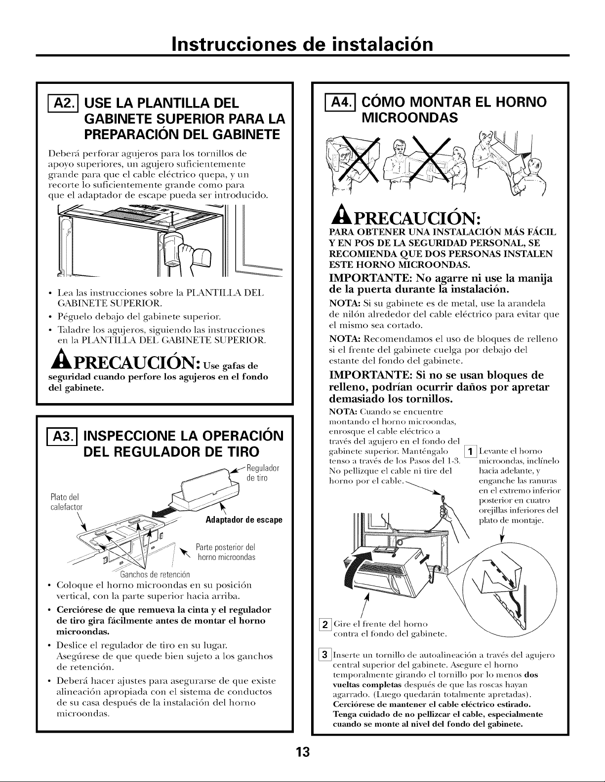
USE LA PLANTILLA DEL
GABINETE SUPERIOR PARA LA
PREPARACION DEL GABINETE
Deberd perforar agt{jeros para los tornillos de
apoyo superiores, un agt{jero suficientemente
grande para que el cable el_cuico quepa, y un
recorte lo suficientemente grande como para
que el adapmdor de escape pueda set inuoducido.
• I,ea las instrucciones sobre la PI,ANTII_LA DEL
GABINETE SUPERIOR.
• Pdguelo deb_jo del gabinete superior.
• Taladre los agujeros, siguiendo las instrucciones
en la PLANTILLA DEL GABINETE SUPERIOR.
,PRECAUCION: Usegalasde
seguridad cuando perfore los agujeros en el rondo
del gabinete.
INSPECCIONE LA OPERACION
DEL REGULADOR DE TIRO
detiro
Platodel
calefactor
Adaptadorde escape
COMO MONTAR EL HORNO
MICROONDAS
PRECAUCION:
PARA OBTENER UNA INSTALACION _ F,_CIL
Y EN POS DE LA SEGURIDAD PERSONAL, SE
RECOMIENDA QUE DOS PERSONAS INSTALEN
ESTE HORNO MICROONDAS.
IMPORTANTE: No agarre ni use la manija
de la puerta durante la instalaci6n.
NOTA: Si su gabinete es de metal, use la arandela
de nil6n ahededor del cable el6ctrico para evimr que
el mismo sea cortado.
NOTA: Recomendamos el uso de bloques de relleno
si el flente del gabinete cuelga pot deb_jo del
estante del fondo del gabinete.
IMPORTANTE: Si no se usan bloques de
relleno, podrian ocurrir dafios por apretar
demasiado los tornillos.
NOTA: Cuando se encuentre
montando el homo microondas,
enrosque el cable el6ctrico a
trav6s del agt{iero en el tondo del
gabinete superkm Mant6ngalo
tenso a trav6s de los Pasos del 1-3.
No pellizque el cable ni tire del
homo pot el
_ .cxante el homo
microondas, inclfnelo
hacia adelante, y
enganche las _.mmas
en el extremo interior
posterior en cuatro
orgjillas inlcriores del
plato de monta.ie.
Parteposteriordel
homomicroondas
/
Ganchosde retenci6n
• (;oloque el homo microondas en su posicidn
vertical, con la parte superior hacia arriba.
• Cerei6rese de que remueva la einta y el regulador
de tiro gira faeilmente antes de montar el horno
mieroondas.
• Deslice el regulador de tiro en su lugaL
AsegOrese de que quede bien st{jeto a los ganchos
de retencidn.
• Deber5 hacer t_justes para asegurarse de que existe
alineacidn apropiada con el sistema de conductos
de su casa despu4s de la insmlacidn del homo
microondas.
/
_Gire el tiente del homo
contra el fondo del gabinete.
_Inserte un tornillo de autoalineaci6n a trav6s del agujero
central superior del gabinete. Asegure el horno
temporalmente girando el tornillo pot lo menos dos
vueltas completas despu6s de que las roscas hayan
agarrado. (Luego quedarfin totalmente apretadas).
Cerci6rese de mantener el cable el6ctrico estirado.
Tenga cuidado de no pellizcar el cable, especiaJmente
cuando se monte aJ[nivel dd rondo del gabinete.
13
Page 38
Instrucciones de instalacion
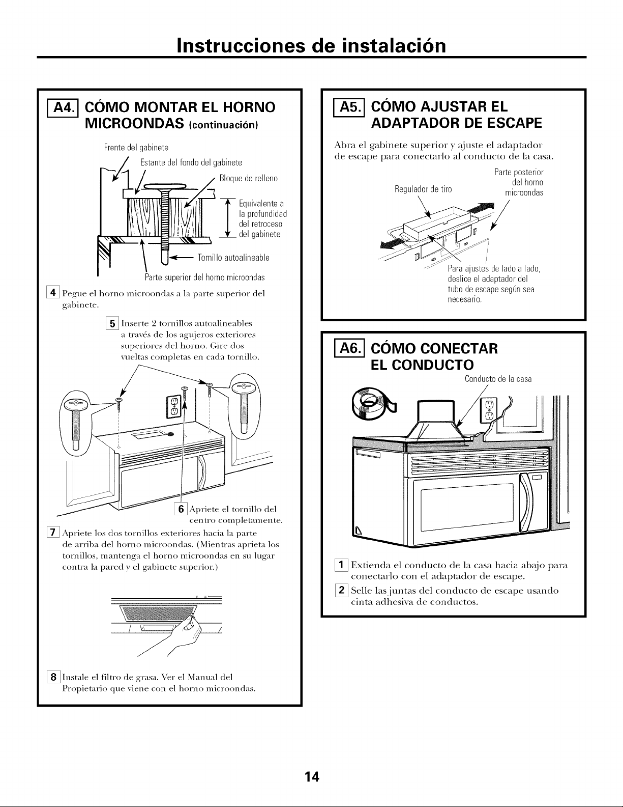
COMO MONTAR EL HORNO
MICROONDAS (continuacion)
Frentedelgabinete
Estantedelfondedelgabinete
Bloquede relleno
la profundidad
del retroceso
T quivalente a
del gabinete
Tornilloautoalineable
Partesuperiordelhornomicr00ndas
[_ Pegue el horno microondas a la parte superior del
gabinete.
[] Inserte 2 tornillos autoalineables
a tray, s de los agu, ieros exteriores
superiores del horno. (;ire dos
vueltas completas en cada tornillo.
COMO AJUSTAR EL
ADAPTADOR DE ESCAPE
Abra el gabinete superior y ajuste el adapmdor
de escape para conecmrlo al conducto de la casa.
Parteposterior
Reguladordetiro
Paraajustesde ladealade,
desliceel adaptadordel
tubodeescapesegOnsea
necesario.
delhomo
microondas
COMO CONECTAR
EL CONDUCTO
Conductodela casa
Apriete el tornillo del
centro completamente.
[] Apriete los dos tornillos exteriores hacia la parte
de arriba del horno microondas. (Mientras aprieta los
tornillos, mantenga el horno microondas en su lugar
contra la pared y el gabinete superior.)
[] Instale el filtro de el Manual del
Propietario que xiene con el homo microondas.
grasa.
\.%r
14
Extienda el conducto de la casa hacia ab_jo
conecmrlo con el adapmdor de escape.
Selle lasjuntas del conducto de escape usando
cinta adhesiva de conductos.
para
Page 39

Instrucciones de instalacion
ESCAPE POSTERIOR EXTERNO (Conducto horizontal)
PERSPECTIVA GENERAL
DE LA INSTALACION
B1. Piepme la paxed postexiox
B2. Gdmo adherii el plato
de mont_je a la paxed
B3. Prepare el gabinete supexiox
B4. Adapte el calefactor
BS. Monte el hoxno micxoondas
|
ZZZzzzizz7
I-_ COMO PREPARAR LA PARED
POSTERIOR PARA EL ESCAPE
POSTERIOR
Necesita coxtax una abextma en la paxed postexiox
paxa el escape extexioL
• Lea las instmcciones en la PLANTILLA PARA LA
PARED POSTERIOR.
• P_guela con cinm adhesiva a la pared postexiox;
aline_indola con los agx{jeros previamenm pexfoxados
para los agx{jeros A y B en el plato de la pared.
• Goxte la apermxa, siguiendo las instmcciones de la
PIANTILLA PARA LA PARED POSTERIOR.
I-_ COMO ADHERIR EL PLATO
DE MONTAJE A LA PARED
Pegue el plato a la pared usando los tomillos basculanms.
Pox lo menos un tomillo de madexa debe sex usado paxa
peg;u el plato al posm de viga de la paxed.
_!_ Remueva las mariposas de los toxnillos.
Insmte los tornillos en el plato de mont;_je a trav6,s
de los agx{jeros dise_/ados paxa colocaxse conua la
pared de mampostmfa seca y pegue oua vez las
maxiposas de ¾" a cada toxnillo.
15
Page 40
Instrucciones de instalacion
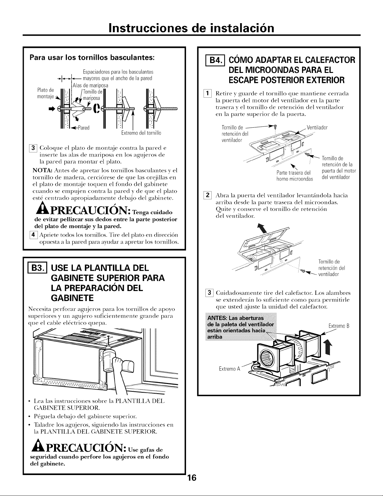
Para usar los tornillos basculantes:
Espaciadores para los basculantes
-_1-.-_!_ mayores que el ancho de la pared
Platode
monta
O
[] Goloque el plato de mont_{ie contra la pared e
inserte las alas de mariposa en los agt{jeros de
la pared para monmr el plato.
NOTA: Antes de apremr los tornillos basculantes y el
tornillo de madera, cercidrese de que las orejillas en
el plato de mont_je toquen el fondo del gabinete
cuando se empt{jen conua la pared y de que el plato
est_ centrado apropiadamente deb_jo del gabinete.
IAlas de mariposa
Extremodeltornillo
PRECAUCION: Tenga cuidado
de evitar pellizcar sus dedos entre la parte posterior
del plato de montaje y la pared.
[] Apfiete todos los tornillos. Tire del plato en direcci6n
opuesm a la pared pa_ ayudar a apremr los tornillos.
I-_ COIVIOADAPTAR ELCALEFACTOR
DELMICROONDAS PARAEL
ESCAPEPOSTERIOR EXTERIOR
Retire y guarde el tornillo que mantiene cerrada
la puerta del motor del ventilador en la parte
trasera y el tornillo de retencidn del ventilador
en la parte superior de la puerta.
Tornillode _ . Ventilador
retenci6ndel =_ _ ..........
ventilador
....__:J_ _ Tornillode
_--_ _. retenci6nde la
Partetraseradel puertadelmotor
homomicroondas delventilador
% Abra la puerto del ventilador levant;indola hacia
arriba desde la parte uasera del microondas.
Quite y conserve el tornillo de retencidn
del ventilador.
jj-J
USE LA PLANTILLA DEL
GABINETE SUPERIOR PARA
LA PREPARACION DEL
GABINETE
Necesita perform agt_jeros para los tornillos de apoyo
superiores y un agt_jero suficientemente grande para
que el cable el_ctrico quepa.
• Lea las instrucciones sobre la PI_ANTII_LA DEL
GABINETE SUPERIOR.
• Pdguela deb_jo del gabinete superior.
• Taladre los agt{jeros, siguiendo las instrucciones en
la PLANTILLA DEL GABINETE SUPERIOR.
"_"J_ _ Tornillode
---_:_ retenci6ndel
_ ventilador
[] Guidadosamente tire del calefacto_. Los alambres
se extender_n lo suficiente como para permitirle
que usted ;0uste la unidad del calefacto_.
Extremo B
Extremo A
A /,
== PRECAUCI N: Usegafas de
seguridad cuando perfore los agujeros en el fondo
del gabinete.
16
Page 41

Instrucciones de instalacion
I-_ C01VIOADAPTAR EL CALEFACTOR
DEL MICROONDAS PARAEL
ESCAPE POSTERIOREXTERIOR
(continuacion)
_Rote la unidad 180 ° en sentido contrario alas
agt!jas del relqj.
Antes de la rotaci6n
_rior del_
homomicroondas Parteposterior
Suavemente remueva los alambres de las rantlras.
Redirija los alambres a tray, s de las ranuras en el
otto lado de la unidad del calefactor.
Antesde redirigirlos Despu6sderedirigirlos
Despu6sdela rotaci6n
delhomo
microondas
_7_ Coloque la unidad del calefactor de nuevo en
la abertura.
ExtremoA
Extremo B
-/k PRECAUCION: No tire
ni estire los cables del calefactor. Cerci6rese
de que los alambres no estfin pellizcados.
NOTA: Las aberturas del escape del calefactor
deberfin encajar con las aberturas del escape
en la parte posterior del horno microondas.
[] Asegure el ventilador del homo de microondas
usando el tornillo de retencidn del Paso 2.
Alambresdirigidosa trav6sdel Alambresdirigidosatrav6sdel
lado derecho ladoizquierdo
Ruede la unidad del calefactor 90 ° de forma tal
que las abermras de la paleta del ventilador est_n
orientadas hacia la parte posterior del homo
microondas.
Antesdela rotacidn
__ __!__ior deI
homomicroondas
Despu6sde la rotacidn
art_Je/_ror
delhomo
microondas
ntilador
.--_ . L_,_ _...
Parteposterior Tornillode
delhomo retencidndel
microondas ventilador
[]
Deslice el adapmdor de escape denuo de la parte
uasera del microondas t_j_ndolo denuo de las
lengfiems de bloqueo inferiores. Verifique que
la bisagra del regulador de tiro se encuenue
insmlada de modo que quede en la parte superior
y que el regulador de tiro se mueva libremente.
Vuelva a instalar el tornillo superior del motor
del ventilador a tray,s del adapmdor, la puerto
del ventilador y dentro de la parte trasera del
microondas. Cierre la puerto del ventilador
y asegfire lo usando los tornillo del Paso 1.
Tornillode
retencidndel
ventilador
; -- hornomicroondas
Parteposteriordel
17
Gu[a
Ada
gtador LengLietas Tornillode
debloqueo retenci6nde la
(nomostrado) puertadelmotor
delventilador
Page 42

Instrucciones de instalacion
COMO MONTAR EL HORNO
MICROONDAS
Frentedelgabinete
Estantedelfondodelgabinete
Bloquederelleno
Equivalentea
la profundidad
delretroceso
delgabinete
Tornilloautoalineable
PRECAUCION:
PARA OBTENER UNA INSTALACION M_ F2{CIL
Y EN POS DE LA SEGURIDAD PERSONAL, SE
RECOMIENDA QUE DOS PERSONAS INSTALEN
ESTE HORNO MICROONDAS.
IMPORTANTE: No agarre ni use la manila
de la puerta durante la instalaci6n.
NOTA: Si su gabinete es de metal, ose la arandela de
nil6n ahededor del cable el6cuico para evitar que el
mislno sea cortado.
NOT.&: Recomendamos el uso de bloques de relleno
si el frente del gabinete cuelga por deb_jo del
estante del rondo del gabinete.
IMPORTANTE: Si no se usan bloques de
relleno, podrian ocurrir dafios por apretar
demasiado los tornillos.
NOTA: Cuando se encuentre
montando el homo microondas,
enrosque el cable el6ctrico a
trav6s del agt_jero en el tondo del
gabinete superkm Mant6ngalo
tens() a trav6s de los Pasos del 1-3.
No pellizque el cable ni tire del
horno pot el cable.
_ exante el homo
microondas, inclfnelo
hacia adelante, y
eng',mche las l_,mm_as
en el extremo interior
posterior en cuatro
orcjillas inlcriores del
plato de montaje.
Parte superior del homo microondas
_ Pegue el horno microondas a la parte superior
del gabinete.
_ nserte 2 tornillos autoalineables
a tray, s de los agu.ieros exteriores
superiores del horno. Gire dos
vueltas completas en cada tornillo.
Apriete el tornillo del
centro completamente.
[] Apriete los dos tornillos exteriores hacia la parte
de arriba del horno microondas. (Mientras aprieta los
tornillos, mantenga el horno microondas en su lugar
contra la pared ) el gabinete superior.)
I_ lit_
Gire el tiente del homo
contra el fondo del gabinete.
[]Inserte un tornillo de autoalineaci6n a trav6s del agujero
central superior del gabinete. Asegure el horno
temporalmente girando el tornillo pot lo menos dos
vueltas completas despu6s de que las roscas hayan
agarrado. (Luego quedarfin totalmente apretadas).
Cerci6rese de mantener el cable el6ctrico estirado.
Tenga cuidado de no pdlizcar el cable, especiMmente
cuando se monte aJ nivel del rondo del gabinete.
_ Instale el filtro de grasa. \.%r el Manual del
Propietario que xiene con el homo microondas.
18
Page 43

Instrucciones de instalacion
RECIRCULACION (Sin conducto de ventilacion)
PERSPECTIVA GENERAL
DE LA INSTALACION
C1. G6mo adherir el plato de montaje
a la pared
Ci. Prepare el gabinete superior
C3. Adapte el calefactor
C4. Monte el homo microondas
C5. Insmle el filtro de carbonilla
I-_ COMO ADHERIR EL PLATO
DE MONTAJE A LA PARED
Pegue el plato a la pared usando los tornillos
basculantes. Pox lo menos un tomillo de madera debe
sex usado paxvlpegar el plato al posm de la pared.
f_ Remueva las mariposas del basculante de
los tornillos.
[] Inserte los tornillos en el plato de mont_je a travds
de los agx{jeros disefiados para sex insertados en la
pared de mamposterfa seca y pegue otra vez las
mariposas de :X" en cada tornillo.
Para usar los tornillos basculantes:
Goloque el plato de mont_{je contra la pared
e inserte las alas de mariposa en los agx{jeros
de la pared para monmr el plato.
NOTA: Antes de apremr los tornillos basculantes
y los tornillos de madera, cercidrese de que las orejillas
en el plato de mont_je toquen el fondo del g_d)inete
cuando son empx{jadas conua la pared y de que el plato
est6 cenm_do apropiadamente deb_io del gabinete.
*(kPRECAUCION: Tenga cuidado
de evitar pellizcar sus dedos entre la parte posterior
del plato de montaje y la pared.
_ Apriete todos los tornillos. Tire del plato en direccidn
opuesm a la pared para ayudar a apremr los mrnillos.
USE LA PLANTILLA DE
GABINETE SUPERIOR PARA LA
PREPARACION DEL GABINETE
Deber_ perforar agx{jeros para los tornillos de apoyo
superiores y un agujero suficientemente grande para
que el cable el_ctrico quepa.
Platode
rnonta
N,
Espaciadores para los basculantes
mayores que el ancho de la pared
I
iAlas de manposa
•Pared
Extremodeltornillo
• Lea las instrucciones sobre la PI_ANTII_LA DEL
GABINETE SUPERIOR.
• Pdguela deb_jo del gabinete superior.
• Taladre un agujero, siguiendo las instrucciones
en la PLANTILLA DEL GABINETE SUPERIOR.
A
mLPRECAUCIuN: Usegafas de
seguridad cuando perfore los agujeros en el fondo
del gabinete.
19
Page 44

Instrucciones de instalacion
I-_ COMO ADAPTAR EL CALEFACTOR
DELMICROONDASPARA
LA RECIRCULACION
Retire y guarde el tornillo que mantiene cerrada
la puerta del motor del ventilador en la parte
trasera y el tornillo de retencidn del ventilador
en la parte superior de la puerto.
Tornillode _ . Ventilador
retenci6ndel ji -
ventilador
Tornlllode
..._f_"_ retenc6ndela
Partetraseradel puertadelmotor
homomicroondas delventilador
Abra la puerto del ventilador levantdndola hacia
arriba desde la parte trasera del microondas.
Quite y conserve el tornillo de retencidn
del ventilado_.
Ruede la unidad del calefactor 90° de forma tal
que las abermras de la paleta del ventilador est_,n
orienmdas hacia el frente del microondas.
Ruede 4_
I
.._ -/
_ Cuidadosamente tire del calefacto_. I.os alambres
se extenderdn lo suficiente como para permitMe
que usted _tjuste la unidad del calefacto_.
_'_Tornillo de
retenci6ndel
ventilador
NOTA: Cercidrese de que los alambres permanecen
encaminados en las ranuras del marco del motor.
20
Page 45

Instrucciones de instalacion
COMO ADAPTAR EL CALEFACTOR
DEL MICROONDAS PARA LA
RECIRCULACION (continuacion)
Coloque la unidad del calefactor de
en la abermra.
p
iltlevo
PRECAUCION: Notireni
estire los cables del calefactor. Cerci6rese de que
los alambres no estfin pellizcados.
Cierre la puerto del ventilador. Asegure el
ventilador y la puerta del ventilador del homo
de microondas usando los tornillos de retencidn
de los Pasos 1 y 2.
Tornillode
retenci6ndel /- Ventilador
ventilador __-_"
Tornillode
.J.J _,._-- . __( ...--_,..2>_%._'=- retenci6ndela
....__-t"f._:J -_ _ puertadel motor
"_" _ _-_ del ventilador
Parteposterior Tornillode
delhomo retenci6ndel
microondas ventilador
C0MO MONTAR EL HORNO
MICROONDAS
PRECAUCION: PARA OBTENER
UNA INSTAIACION MAS FACIL Y EN POS DE IA
SEGURIDAD PERSONAL, SE RECOMIENDA QUE
DOS PERSONAS INSTALEN ESTE HORNO
MICROONDAS.
IMPORTANTE: No agarre ni use la manija
de la puerta durante la instalaci6n.
NOTA: Si su gabinete es de metal, use la arandela de
nildn ahededor del cable el6cuico para evimr que el
mismo sea cormdo.
NOTA: Recomendamos el uso de bloques de relleno
si el flente del gabinete cuelga pot deb_{jo del estante
del fondo del gabinete.
IMPORTANTE: Si no se usan bloques de
relleno, podrian ocurrir daflos por apretar
demasiado los tornillos.
NOTA: (:uando se encuentre
montando el homo microondas,
emosque el cable el_ctrico a
trax_s del agujero en el rondo del
gabinete superion Mant_ngalo _!_
tens() a trax_s de los Pasos del 1-3. microondas, inclfnelo
No pellizque el cable ni tire del hacia adelante, }
horno por el cable, enganche las canucas
I.cxante el homo
en el extremo interior
posterior en C/latFo
orejillas interiores del
plato de montaje.
21
Gire el flente del homo
contra el fondo del gabinete.
Page 46

Instrucciones de instalacion
I-_ COMO MONTAR EL HORNO
MICROONDAS (continuacion)
_Inserte un tornillo de autoalineaci6n a trav6s del agujero
central superior del gabinete. Asegure el horno
temporalmente girando el tornillo pot lo menos dos
vueltas completas despu6s de que las roscas hayan
agarrado. (Luego quedarfin totalmente apretadas).
Cerci6rese de mantener el cable el6ctrico estirado.
Tenga cuidado de no pellizcar el cable_ especiaJmente
cuando se monte al nivel del fondo del gabinete.
Frente del gabinete
V_A Estante del fondo del gabinete
Bloquede relleno
. v : la profundidad
I !\t l; lt!V/llll/delretroceso
J.._ n, ui,/l_lllL/L/lll 4, delgabinete
Partesuperiordelhomomicroondas
[] Pegue el horno microondas a la parte superior
del gabinete.
_ nserte 2 tornillos autoalineables
a trax6s de los agu.ieros exteriores
superiores del horno. Gire dos
xueltas completas en cada tornillo.
I-_ C0MO INSTALAR EL FILTRO
DE CARBONILLA
Remueva los 3 tornillos situados encima de
unidad que sostengan la parrilla en el lugar,
usando un destornillador de estrella #1.
_Abra la puerta.
Remueva la rejilla.
Deslice la rejilla hacia la izquierda y tire de ella
directamente hacia afuera.
Filtrode
Insmle el filtro de carbonilla. Cuando estd insmlado
correcmmente, la malla del filtro deberfa esmr
visible desde el flente.
Reemplace la reiilla con los tornillos.
Apriete el tornillo del
centro completamente.
[] Apriete los dos tornillos exteriores hacia la parte
de arriba del horno microondas. (Mientras aprieta los
tornillos, mantenga el horno microondas en su lugar
contra la pared )el gabinete superior.)
I" lit----
_ Instale el fihro de grasa. Vet el Manual del
Propietario que _iene con el horno microondas.
Insertela mallahaciaarriba
[_ Cierre la puerta.
22
Page 47

Instrucciones de instalacion
ANTES DE COMENZAR A USAR
SU HORNO MICROONDAS
-i'7"] Cercidrese de que el homo ha sido insmlado
de acuerdo con las instrucciones.
%
'_'1 Lea el Manual del Propiemrio.
Enchufe el cable el_ctrico en un tomacorriente
exclusivo de 15 a 20 amperios.
|1
-_ emueva todos los materiales de embal_{ie
del homo microondas.
Instale el aro rotatorio y con ruedas en
I
la cavidad.
'-_ eemplace el fllsible de la casa o encienda
de nuevo el interruptoL
I
['_ GUARDE ESTAS INSTRUCCIONES PARA
EL USO DEL INSPECTOR LOCAL.
23
Page 48

t DE68-03698A49-40615-1
09-09 JR hnpreso en Malasia
 Loading...